06/2020© 2020 Menard, Inc., Eau Claire, WI 54703
To Reduce The Risk Of Injury, User Must Read And
Understand Operator’s Manual. Save These Instructions For Future Reference.
OPERATOR’S MANUAL
242-1518
CAUTION:
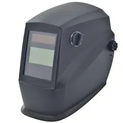
Auto-Darkening
Welding Helmet
Customer Service: 1-855-692-6872 Distributed by Menard, Inc. Eau Claire, WI 54703
Page 1
Page 4
Page 5
Page 6
Page 6
Page 7
Page 7
Page 7
Page 8
Page 8
Page 10
TABLE OF CONTENTS
SAFETY SYMBOLS
TECHNICAL SPECIFICATIONS
OVERVIEW
OPERATION
SELECT THE SHADE NUMBER
SELECT DELAY TIME
SELECT SENSITIVITY
PRE-WELDING CHECK & BATTERY TESTING
RECOMMENDED SETTINGS
MAINTENANCE
Page 10
INSERT THE MAGNIFYING LENS
INSPECTION
Page 1
SAFETY SYMBOLS
Indicates a potentially hazardous situation that, if not avoided, COULD result
in death or serious injury.
WARNING:
Indicates an imminently hazardous situation that, if not avoided, WILL result
in death or serious injury.
DANGER:
Indicates a potentially hazardous situation that, if not avoided, MAY result in
minor or moderate injury.
CAUTION:
Indicates important information, which if not followed, MAY cause damage to
equipment.
NOTICE:
Read and understand this entire instruction manual before attempting to assemble,install, operate
or maintain this tool. Failure to comply with the instructions may result in serious personal injury
and/or property damage!
The following signal words are used to emphasize safety warnings that must be followed when
using this tool:
IMPORTANT SAFETY INSTRUCTIONS
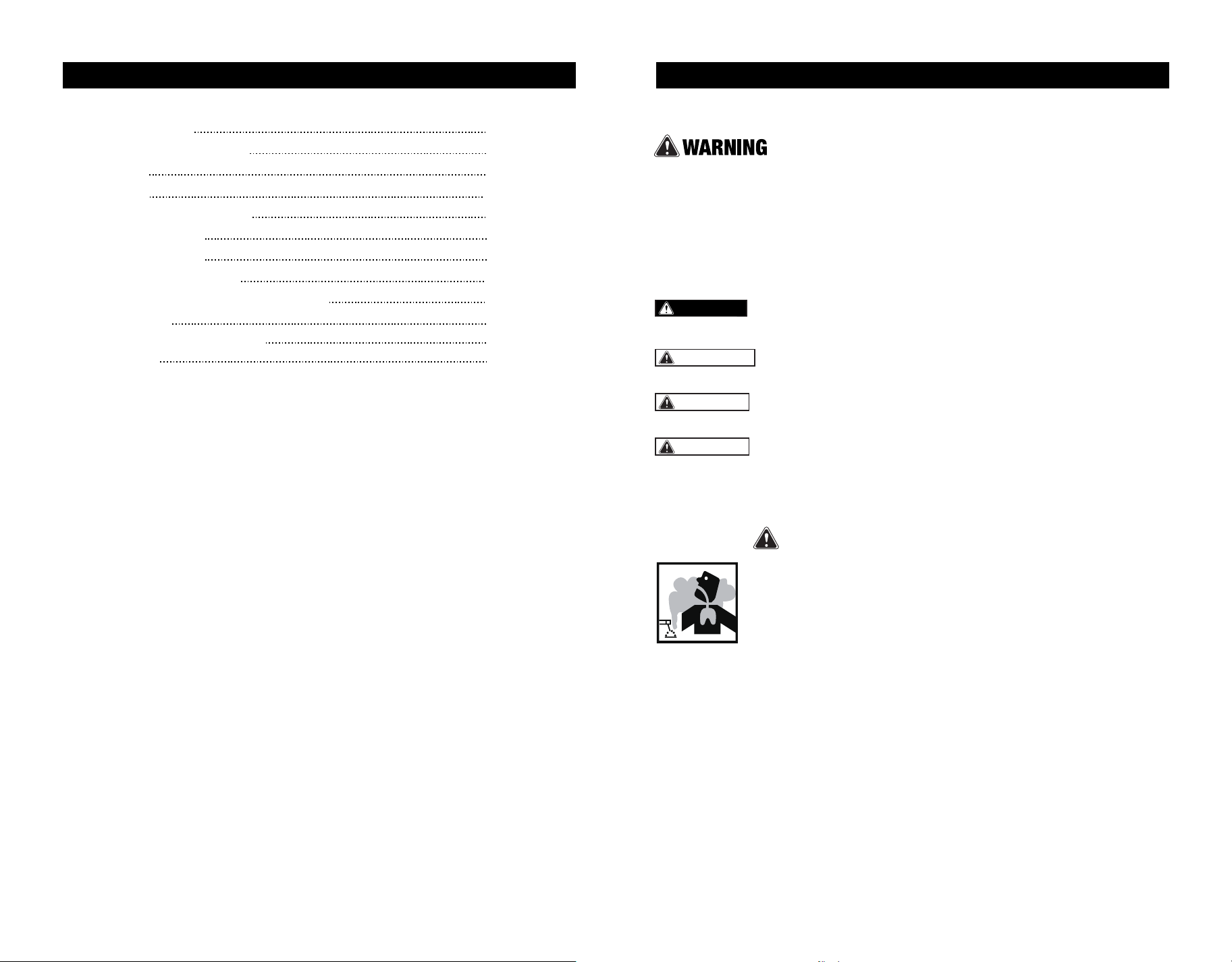
FUMES AND GASES can be hazardous !
Welding produces fumes and gases that are hazardous to your health.
• Keep your head out of the fumes. Do not breathe in the fumes.
•
If inside, ventilate the area and/or use exhaust at the arc to remove welding
fumes and gases.
• If ventilation is poor, use an approved air-supplied respirator.
• Read the manufacturer's instructions for metals, consumables, coatings, cleaners, and
degreasers.
• Work in a confined space only if it is well ventilated, or while wearing an air-supplied respirator.
Always have a trained watchperson nearby. Welding fumes and gases can displace air and
lower the oxygen level causing injury or death. Be sure the breathing air is safe.
• Do not weld in locations near degreasing ,cleaning, or spraying operations. The heat and
rays of the arc can react with vapors to form highly toxic and irritating gases.
• Do not weld on coated metals, such as galvanized, lead, or cadmium plated steel, unless the
coating is removed from the weld area, the area is well ventilated, and if necessary, while wear-
ing an air-supplied respirator.The coatings and any metals containing these elements can give
off toxic fumes if welded.
SAFETY SYMBOLS
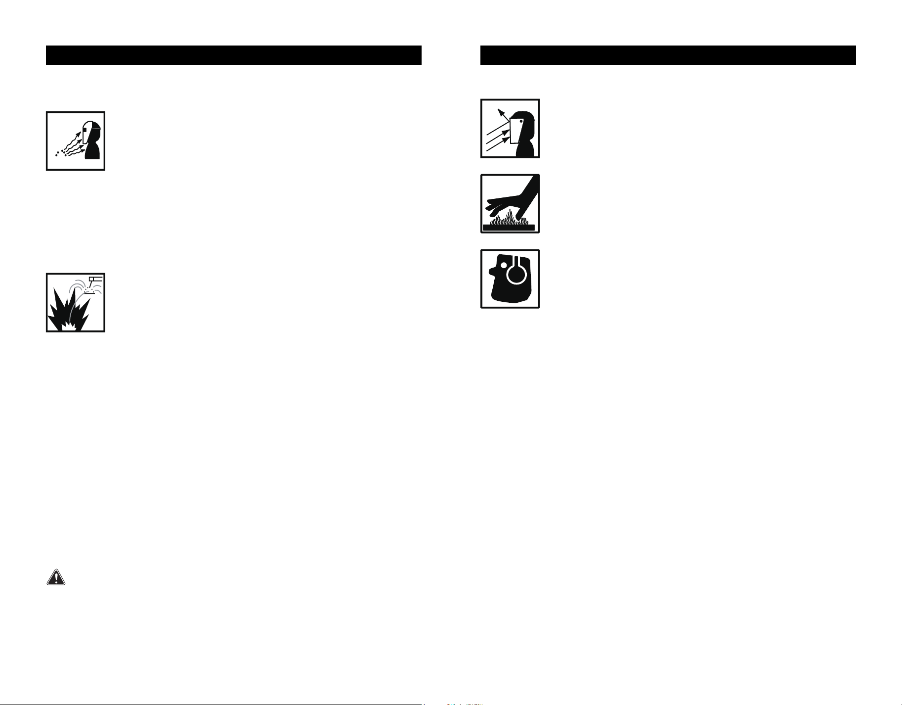
HOT PARTS can cause severe burns !
• Never touch hot parts bare handed.
• Allow adequate cooling period before touching work piece.
NOISE can damage hearing !
• Noise from some processes or equipment can damage hearing.
• Wear approved ear protection if noise level is high.
FLYING METAL can injure eyes !
• Wear ANSI approved safety glasses with side shields under your welding
helmet.
• Welding, chipping, wire brushing, and grinding cause sparks and flying metal.
As welds cool, they can throw off slag.
GENERAL INFORMATION
The auto-Darkening Welding Helmet does
not protect against severe impact hazards,
such as fractured grinding wheels or abrasive
discs,explosive devices or corrosive
liquids.Machine guards or eye splash
protection must be used when these hazards
are present.
The auto-darkening welding filters are
designed for Arc welding or cutting applica-
tions.The unit is suitable for all Arc welding
processes such as MIG,MAG,TIG,
SMAW,Plasma Arc,and Carbon Arc.
This auto-darkening welding helmet is not
recommended for "overhead" welding
applications, laser welding or Iaser cutting
applications.
The auto darkening lens has a built-in
passive UV/IR filter that works independently
, and provides permanent UV/IR protection at
W13 or higher (#13 welding glass provides
UV/IR, visible lights protection at W13 as per
ANSI standards), even in case of an electron-
ic failure.
The auto-darkening welding filter should
always be used with original inner and outer
cover lenses.
The manufacturer is not responsible for any
failure due to modifications to the welding
filter or the use of the filter from any other
manufacturer's helmet.
Page 2 Page 3
SAFETY SYMBOLS
Never look at arc welding without proper eye protection. Arc rays from the
welding process produce intense visible and invisible (ultraviolet and infrared)
rays that can burn eyes and Skin. Hot sparks fly off from the weld and can burn
eyes and skin.
Wear a welding helmet fitted with a proper shade of filter to protect your
face and eyes when welding or watching.
• Wear approved safety glasses with side shields under your helmet.
• Use protective screens or barriers to protect others from flash and glare. Warn others in the area
not to watch the arc.
• Wear protective clothing made from durable, flame resistant materials, leather welding gloves
and full foot protection.
• Always keep a fire extinguisher readily available and watch for fire.
• Protect yourself and others from flying sparks and hot metal.
• Do not weld where flying sparks can strike flammable material.
• Remove all flammable materials from the welding area. If this is not possible, tightly cover them
with approved covers
• Be alert that welding sparks and hot materials from welding can easily go through small cracks
and openings to adjacent areas.
• Be aware that welding on a ceiling, floor, bulkhead, or partition can cause fire on the hidden side.
• Do not weld on closed containers such as tanks, drums, or pipes, unless they are properly
prepared according to AWS F4.1 standards.
• Connect work cable to the work as close to the welding area as practical to prevent welding
current from traveling long, possibly unknown paths and causing electric shock and fire
hazards.
• Never use arc welder to thaw frozen pipes.
• Remove electrode from holder when not in use.
• Wear oil-free protective garments such as leather gloves, heavy shirt, trousers with no cuffs,
high shoes, and a cap.
• Remove any combustibles, such as butane lighters or matches, from yourself and the surround-
ings near the welding location before doing any welding.
• Welding or cutting equipment produces fumes or gases which contain chemicals known to the
State of California to cause birth defects and, in some cases, cancer. (California Health & Safety
Code Section 25249.5 et seq.)
California Proposition 65 Warnings !
ARC RAYS can burn eyes !
Welding on closed containers, such as tanks, drums, or pipes, can cause
them to explode. Sparks can fly off from the welding arc. The flying sparks,
hot work piece, and hot equipment can cause fires and burns. Accidental
contact of electrode to metal objects can cause sparks, explosion,
overheating, or fire. Check and be sure the area is safe before doing any
welding.
WELDING can cause fire or explosion !
TECHNICAL SPECIFICATIONS
TECHNICAL SPECIFICATIONS
OVERVIEW
WARNING:
NOTICE:
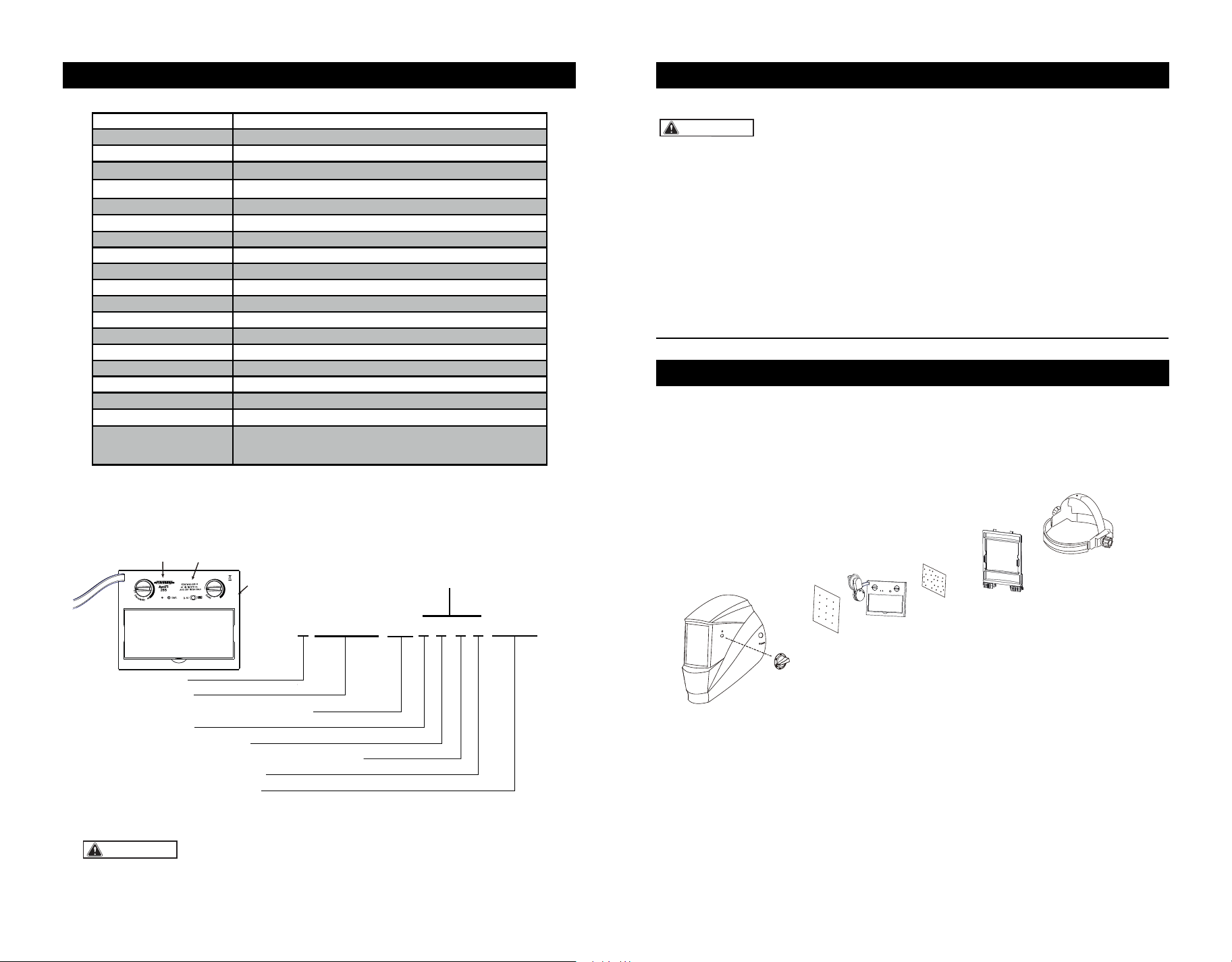
MARKING EXPLAINED
This is a sample of EN379 marking only. For the product you are
using, please refer to the marking information on the filter.
ADF Model
Viewing Area
Cartridge Size
Light State
Dark State
UV/IR Protection
Sensors
Grinding
Battery Type
Sensitivity Control
Solar Cell
Delay Control
TIG Rating
Operation Temperature
Storage Temperature
Standards Compliance
AntFi265
98mm x 44mm/3.86" x1.73"
110 x 90 x9mm /4.33" x 3.54" x 0.35"
Shade DIN 4
Variable Shade 5~9/9~13
Permanent Shade DIN 13
Knob Adjustable
1x CR 2450( Replaceable)
Knob Adjustable
Yes
0.1-1.0 Second Continuously Adjustable
-5°C to +55°C (23° F to 131° F)
-20°C to +70°C (-4° F to 158° F)
4
>2Amp
ANSI Z87.1-2015 & CSA Z94.3-2015
& CE EN379:2009-07
18.4oz/507gWeight
Inner cover lens
Outer cover lens
99.3X45.4X1mm/3.91"X1.79"X0.04"
114.5X94X1mm/4.51" X3.70" X0.04"
• Inspect all parts for signs of wear or damage. Any scratched or cracked parts should be
replaced prior to use.
• When stored in extremely cold temperatures, the helmet should be warmed up to ambient
temperature before welding.
• SKIN CONTACT ALLERGIC ALERT! Extra protections must be taken if individuals are
allergic to plastic or other materials that their skin may be in contact with when using
this product.
PARTS LIST
• NEVER place the helmet on a hot surface.
• NEVER open or tamper with the filter cartridge.
• Not for Overhead welding without extra protection.
Page 4 Page 5
4 / 5 -9 / 9-13 AT 1 / 1 / 1 / 2 / 379 CE
Light shade
Dark shades
Identification of the manufacturer
Optical class
Diffusion of light class
Variation in luminous transmittance class
Angle dependency class
Number of the standard
Optical Specifications
Standards
Model
S/N:XXXXXXXXXXXXXAXXX
Serial number
1
Helmet Shell
3
Front Cover Lens
4
Cartridge
5
Inside Cover Lens
7
Lens Retaining Frame
8
Adjustable Headband
6
Lock Switches
2
Adjustable Knob
Optical Specifications 1/1/1/2
OPERATION SELECT DELAY TIME
SELECT SENSITIVITY
RECOMMENDED SETTINGS
WARNING:
ADJUST THE WELDING HELMET
ACCORDING TO YOUR INDIVID-
UAL REQUIREMENTS.
ON/OFF
The solar unit automatically switches ON
when exposed to light.
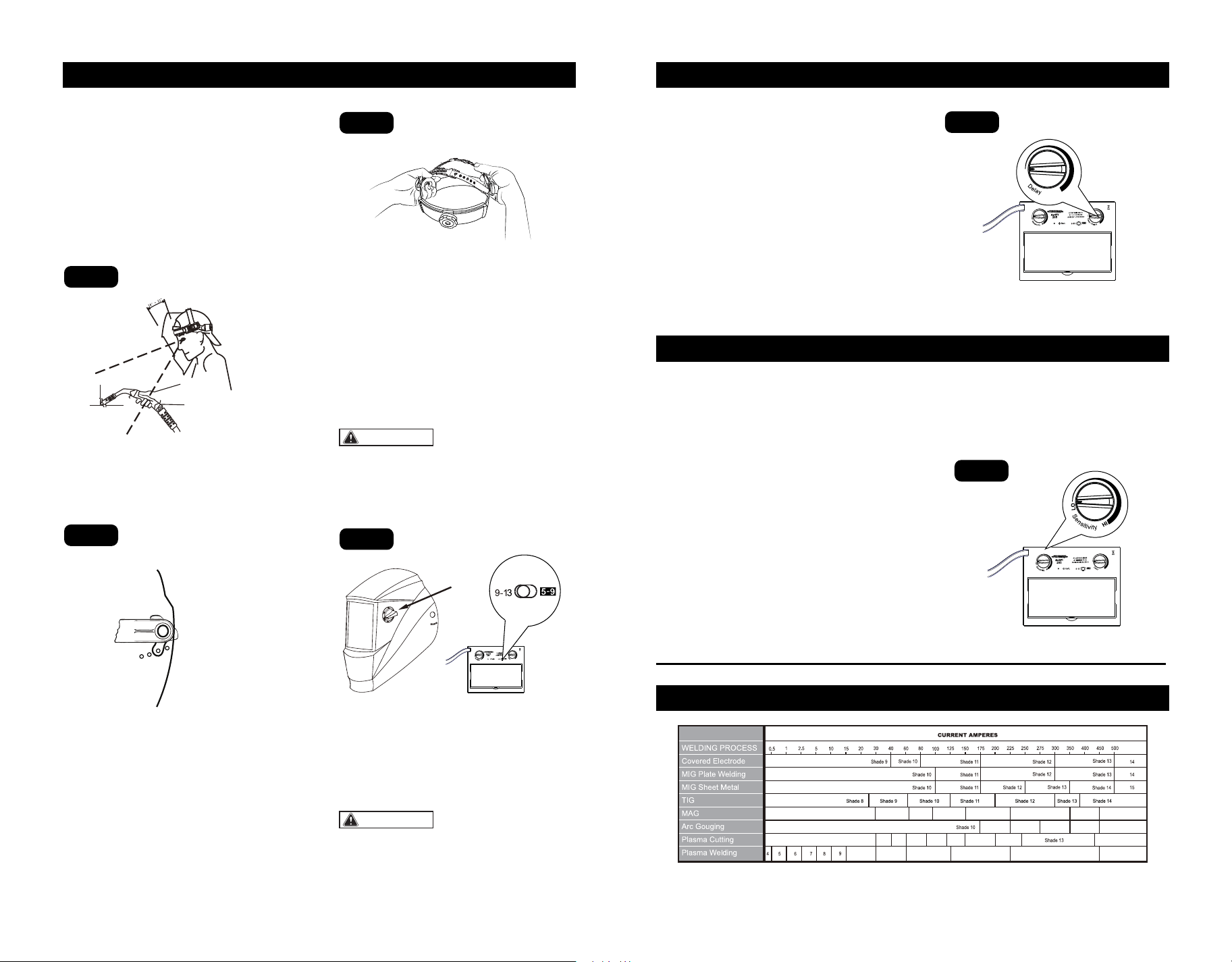
SELECT THE SHADE NUMBER
1) Welding control
Two ranges of shade numbers, "5-9" and
"9-13" are available in the dark state(Fig.4).
2) Grinding control
The arrow on the knob indicates the shade
setting.
Set the adjustable knob to "Grind" position
for grinding application.
The headband should be adjusted both in
circumference and height.
The angle between the face and the helmet is
recommended to be adjusted to 10°-12°
(Fig.1).
ADJUST HEADBAND PER
PERSONAL PREFERENCE.
Use the ratcheting knob on the headband to
adjust width.
Loosen or tighten the top strap to adjust
headband height. Make sure that the helmet
fits firmly on your head(Fig.3).
This welding helmet is featured with continu-
ously adjustable delay time control. The lens
will lighten in 0.1 to 1.0 second upon ambient
temperature and shade setting. By turning
the DELAY knob (Fig.5) clockwise, the delay
time will increase from 0.1 second to 1.0
second.
Turn Knob counterclockwise for tack welding
or production welding with short welds.
Turn Knob clockwise for welding at high
amperage where there is an after glow from
the welding
This welding helmet is featured with
continously adjustable sensitivity control
knob. Sensitivity is a setting of how sensitive
this helmet is responding to the welding arc.
Turn knob clockwise to increase the sensitivi-
ty (Fig.6).
Increase sensitivity:
1) Low amperage welding
2) Used for DC TIG welding
Turn knob counterclockwise to decrease the
sensitivity (Fig.6).
Decrease sensitivity:
1) High ambient light
2) Interference exists
Make sure that the adjustment knob is on the
"5-9" or "9-13" position before starting to
weld.
WARNING:
MAKE SURE TO RESET the knob back to
"5-9" or "9-13" position after grinding.
Adjust helmet’s headband stop to get desired
viewing angle(Fig.2).
Fig.1
Fig.3
Fig.5
Fig.6
Fig.2
9
876 10
Shade 8
Shade 5
Shade 9 Shade 10
Shade 11 Shade 12 Shade 13 Shade 14 Shade 15
Shade 11 Shade 12 Shade 13 Shade 14
Shade 12 Shade 14
Shade 15
Shade 11
Shade 13Shade 12Shade 11Shade 10 Shade 14
REFERENCE ANSI Z49.1-2005
Page 6 Page 7
Fig.4
Adjustment
Knob
Adjust sensitivity setting to properly
condition according to the application
and the environment.
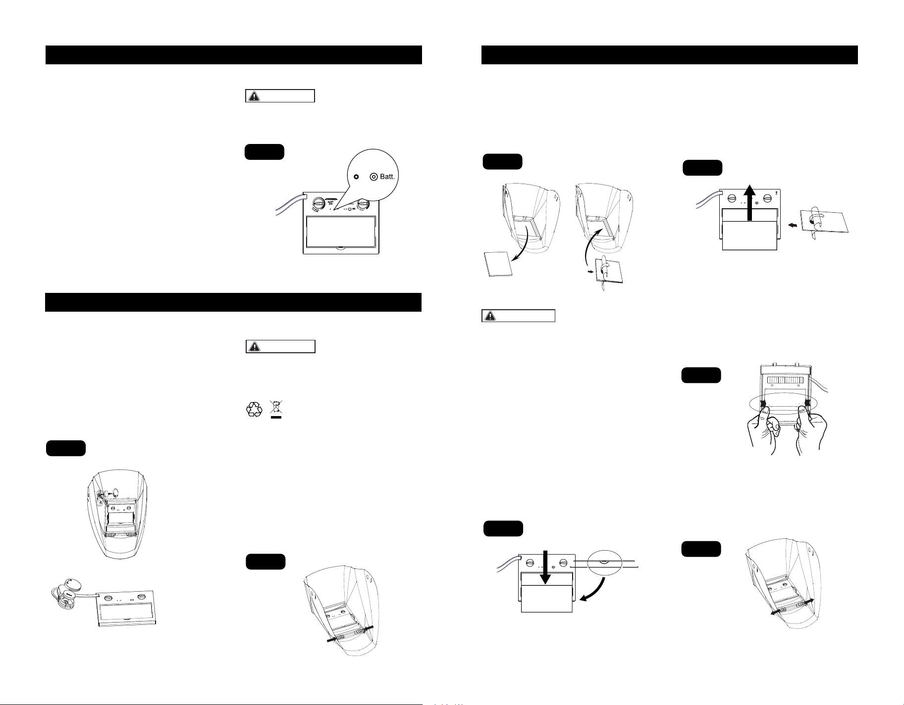
PRE-WELDING CHECK & BATTERY TESTING
MAINTENANCE
MAINTENANCE
CAUTION:
WARNING:
The following procedures should be followed
to perform this testing:
1) Make sure there is enough ambient light to
trigger the auto darkening lens on.
2) Make sure that the adjustment knob is on
the "5-9/9-13" position .
3) Press and hold on the "Batt" button(Fig7)
for 1-2 seconds:
If the LED (Fig.7) is ON, and the lens is
darkening as per shade setting, the helmet is
functioning properly.
If the LED is NOT ON when procedures
above are followed, battery replacement is
required.
If the LED is ON and LCD is not darkening as
per shade setting, the auto darkening lens
may be Defective.
Always test the auto darkening lens before
welding.
REPLACEMENT OF BATTERIES
1) Open the back cover counterclockwise,
2) Gently press one end of the battery to lift
the other end of the battery, then remove it.
3) Put the new battery in.
4) Tighten the back cover clockwise
(Fig.8).
REPLACEMENT OF INNER
COVER LENS
1) Lift the cover lens from the groove of the
inner frame with your hand or hard object, so
that the cover lens pops out of the inner
frame and then push it out(Fig.11).
2) Remove the protective film from the new
cover lens(Fig.12).
3)Push the new cover lens in the recess
along the card slots on both sides of the filter
carefully.
REPLACEMENT OF EXTERIOR
COVER LENS
Remove the front lens by pulling out the
retaining frame by sliding the lock swiches
inward inside the front helmet (Fig.9).
Detach the cartridge from the shield and put
it aside. Remove the old lens cover.
Remove the protective film on the new lens
cover. Put the new lens cover back onto the
shield(Fig10).
Ensure the front cover lens is mounted
before using and the protective film on the
lens cover is removed.
Ensure that the lens is clean and there is no
dirt or spatter covering the 4 sensors at the
front of the filter cartridge.
Fig.7
Fig.8
Fig.9
Fig.10
Fig.11
Fig.12
NOTICE:
Always change both of the batteries when
replacing them.
NEVER put used batteries into household
waste.
Please always have used batteries recycled
properly.
Page 8 Page 9
CR2450
Insert tabs on the back lens retaining frame
under the two slots of the helmet. Slide the
lock switches outward until they snap into
place. (Fig.14).
Fig.14
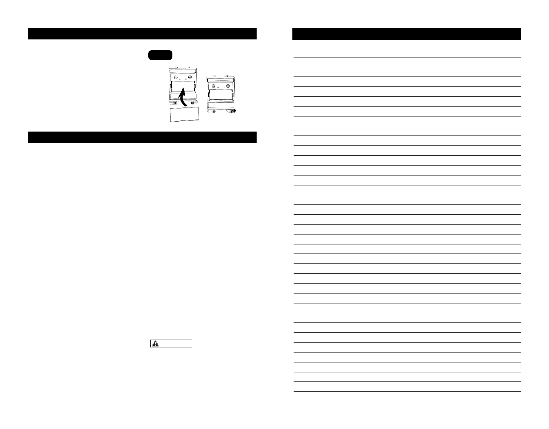
REPLACEMENT OF WELDING
FILTER
Insert tabs of the front lens retaining frame
under the two slots of the back lens retaining
frame. Push the two corners on front lens
retaining frame inward until it snaps into
place(Fig.13).
Fig.13
INSERT THE MAGNIFYING LENS
INSPECTION
NOTES
WARNING:
1.Carefully inspect your Auto-Darkening
Welding Filter regularly.
2.Cracked,pitted or scratched filter glass or
cover lenses will not only affect vision but
also cause lens malfunction,such as UV/IR
protection failure or non-responsive to arc.
3.Worn parts should be replaced immediately
to avoid injury to the eyes.
CLEANING AND DISINFECTION
Clean the helmet with mild soap and
lukewarm water.
Clean the welding filter with a clean lint-free
tissue or cloth.
DO NOT immerse in water.
DO NOT use solvents.
TROUBLESHOOTING
AUTO DARKENING FILTER DOES NOT
DARKEN OR FLICKER:
-Check the lens cover for dirt and spatter that
may be blocking the arc sensors.
-If the sensors are dirty, wipe them clean with
a soft lint-free cloth.
-Check the sensitivity setting recommenda-
tions and increase the sensitivity if possible.
-Increasing lens delay 0.1-0.3 seconds may
also reduce flickering.
-Check batteries and verify that they are in
good condition and installed properly.
-If battery terminals and the contact surface
of the filter are dirty or oxidized(clean both) .
-Shade adjustment knob is on "GRIND"
position, set helmet on “WELD” and/or proper
shade from “5-13”.
THE LENS STAYS DARK AFTER THE
WELD ARC IS EXTINGUISHED, OR THE
AUTO-LENS STAYS DARK WHEN NO
ARC IS PRESENT.
-Fine-tune the sensitivity setting in small
increments. In extreme light conditions, it
may be necessary to reduce the surrounding
light levels
SLOW SWITCHING
-The operating temperature is too low. Don't
use at temperatures of below -5 °C(+23° F).
POOR VISION
-The cover lens and the filter cartridge is
dirty or damaged. Clean the dirty compo-
nents and replace the damaged ones.
-Ensure ambient light is not too low.
-Ensure the shade number is correct and
adjust accordingly.
IRREGULAR DARKENING
-Headband has been set unevenly so the
distance between the eyes and the lens is
different from the left to the right side.
If the described malfunctions cannot be
solved, stop using the helmet immediately
and contact the nearest distributor.
Page 10 Page 11
Fig.15
1).Magnifying lens is sold separately.
2).Insert the magnifying lens into the slot
from the bottom to the top (Fig.15).
SAVE YOUR RECEIPTS
THIS WARRANTY IS VOID WITHOUT THEM
2-YEAR LIMITED WARRANTY
WARRANTY
Page 13
NOTES
Page 12
Auto-Darkening Welding Helmet
The welding helmets are warranted against defects in materials and workmanship for a
period of two (2) years from date of purchase.
This warranty is limited to the repair or replacement of items which are not in compliance
with this warranty. This warranty does not extend to any item subject to unauthorized
repair, alteration, tampering, improper storage or operation, inadequate maintenance,
accident, misuse, abuse or negligent handling. This warranty is not transferrable from the
original purchaser to any subsequent purchaser.
Seller shall in no event be liable or responsible for any injury, damage or loss resulting
either directly or indirectly from, the use or misuse of this product.
This limited warranty is the exclusive remedy of purchaser and the sole obligation of
Seller in connection with any claim, whether in contract,negligence, strict liability, tort or
otherwise.
Do not use these items unless you are trained and experienced in the proper use and
maintenance. Please read the instruction manual carefully to avoid certain situations
which may void this limited warranty.
Customer Service: 1-855-692-6872
Distributed by Menard, Inc. Eau Claire, WI 54703