
Audio and Video Decoder User Manual
DS-6900UDI Decoder User Manual
1
User Manual
COPYRIGHT ©2016 Hangzhou Hikvision Digital Technology Co., Ltd.
ALL RIGHTS RESERVED.
Any and all information, including, among others, wordings, pictures, graphs are the properties of Hangzhou Hikvision Digital
Technology Co., Ltd. or its subsidiaries (hereinafter referred to be “Hikvision”). This user manual (hereinafter referred to be “the
Manual”) cannot be reproduced, changed, translated, or distributed, partially or wholly, by any means, without the prior written
permission of Hikvision. Unless otherwise stipulated, Hikvision does not make any warranties, guarantees or representations,
express or implied, regarding to the Manual.
About this Manual
This Manual is applicable to DS-6900UDI Decoder.
The Manual includes instructions for using and managing the product. Pictures, charts, images and all other information hereinafter
are for description and explanation only. The information contained in the Manual is subject to change, without notice, due to
firmware updates or other reasons. Please find the latest version in the company website (http://overseas.hikvision.com/en/).
Please use this user manual under the guidance of professionals.
Trademarks Acknowledgement
and other Hikvision’s trademarks and logos are the properties of Hikvision in various jurisdictions. Other trademarks
and logos mentioned below are the properties of their respective owners.
Legal Disclaimer
TO THE MAXIMUM EXTENT PERMITTED BY APPLICABLE LAW, THE PRODUCT DESCRIBED, WITH ITS HARDWARE, SOFTWARE AND
FIRMWARE, IS PROVIDED “AS IS”, WITH ALL FAULTS AND ERRORS, AND HIKVISION MAKES NO WARRANTIES, EXPRESS OR IMPLIED,
INCLUDING WITHOUT LIMITATION, MERCHANTABILITY, SATISFACTORY QUALITY, FITNESS FOR A PARTICULAR PURPOSE, AND NON-
INFRINGEMENT OF THIRD PARTY. IN NO EVENT WILL HIKVISION, ITS DIRECTORS, OFFICERS, EMPLOYEES, OR AGENTS BE LIABLE TO
YOU FOR ANY SPECIAL, CONSEQUENTIAL, INCIDENTAL, OR INDIRECT DAMAGES, INCLUDING, AMONG OTHERS, DAMAGES FOR LOSS
OF BUSINESS PROFITS, BUSINESS INTERRUPTION, OR LOSS OF DATA OR DOCUMENTATION, IN CONNECTION WITH THE USE OF THIS
PRODUCT, EVEN IF HIKVISION HAS BEEN ADVISED OF THE POSSIBILITY OF SUCH DAMAGES.
REGARDING TO THE PRODUCT WITH INTERNET ACCESS, THE USE OF PRODUCT SHALL BE WHOLLY AT YOUR OWN RISKS. HIKVISION
SHALL NOT TAKE ANY RESPONSIBILITES FOR ABNORMAL OPERATION, PRIVACY LEAKAGE OR OTHER DAMAGES RESULTING FROM
CYBER ATTACK, HACKER ATTACK, VIRUS INSPECTION, OR OTHER INTERNET SECURITY RISKS; HOWEVER, HIKVISION WILL PROVIDE
TIMELY TECHNICAL SUPPORT IF REQUIRED.
SURVEILLANCE LAWS VARY BY JURISDICTION. PLEASE CHECK ALL RELEVANT LAWS IN YOUR JURISDICTION BEFORE USING THIS
PRODUCT IN ORDER TO ENSURE THAT YOUR USE CONFORMS THE APPLICABLE LAW. HIKVISION SHALL NOT BE LIABLE IN THE EVENT
THAT THIS PRODUCT IS USED WITH ILLEGITIMATE PURPOSES.
IN THE EVENT OF ANY CONFLICTS BETWEEN THIS MANUAL AND THE APPLICABLE LAW, THE LATER PREVAILS.

Audio and Video Decoder User Manual
DS-6900UDI Decoder User Manual
2
Regulatory information
FCC information
FCC compliance: This equipment has been tested and found to comply with the limits for a digital device, pursuant to part 15 of the
FCC Rules. These limits are designed to provide reasonable protection against harmful interference when the equipment is operated
in a commercial environment. This equipment generates, uses, and can radiate radio frequency energy and, if not installed and used
in accordance with the instruction manual, may cause harmful interference to radio communications. Operation of this equipment
in a residential area is likely to cause harmful interference in which case the user will be required to correct the interference at his
own expense.
FCC conditions
This device complies with part 15 of the FCC Rules. Operation is subject to the following two conditions:
1. This device may not cause harmful interference.
2. This device must accept any interference received, including interference that may cause undesired operation.
EU Conformity Statement
This product and - if applicable - the supplied accessories too are marked with "CE" and comply therefore with the applicable
harmonized European standards listed under the Low Voltage Directive 2006/95/EC, the EMC Directive 2004/108/EC, the RoHS
Directive 2011/65/EU.
2012/19/EU (WEEE directive): Products marked with this symbol cannot be disposed of as unsorted municipal waste in the European
Union. For proper recycling, return this product to your local supplier upon the purchase of equivalent new equipment, or dispose of
it at designated collection points. For more information see: www.recyclethis.info.
2006/66/EC (battery directive): This product contains a battery that cannot be disposed of as unsorted municipal waste in the
European Union. See the product documentation for specific battery information. The battery is marked with this symbol, which
may include lettering to indicate cadmium (Cd), lead (Pb), or mercury (Hg). For proper recycling, return the battery to your supplier
or to a designated collection point. For more information see: www.recyclethis.info.

Audio and Video Decoder User Manual
DS-6900UDI Decoder User Manual
3
Safety Instruction
These instructions are intended to ensure that user can use the product correctly to avoid danger
or property loss.
The precaution measure is divided into “Warnings” and “Cautions”
Warnings: Serious injury or death may occur if any of the warnings are neglected.
Cautions: Injury or equipment damage may occur if any of the cautions are neglected.
Warnings Follow these
safeguards to prevent
serious injury or death.
Cautions Follow these
precautions to prevent
potential injury or
material damage.
Proper configuration of all passwords and other security settings is the responsibility of the
installer and/or end-user.
In the use of the product, you must be in strict compliance with the electrical safety regulations of
the nation and region. Please refer to technical specifications for detailed information.
Input voltage should meet both the SELV (Safety Extra Low Voltage) and the Limited Power Source
with 100~240 VAC or 12 VDC according to the IEC60950-1 standard. Please refer to technical
specifications for detailed information.
Do not connect several devices to one power adapter as adapter overload may cause over-heating
or a fire hazard.
Please make sure that the plug is firmly connected to the power socket.
If smoke, odor or noise rise from the device, turn off the power at once and unplug the power
cable, and then please contact the service center.

Audio and Video Decoder User Manual
DS-6900UDI Decoder User Manual
4
Preventive and Cautionary Tips
Before connecting and operating your device, be advised of the following tips:
Ensure unit is installed in a well-ventilated, dust-free environment.
Unit is designed for indoor use only.
Keep all liquids away from the device.
Ensure environmental conditions meet factory specifications.
Ensure unit is properly secured to a rack or shelf. Major shocks or jolts to the unit as a result
of dropping it may cause damage to the sensitive electronics within the unit.
Use the device in conjunction with an UPS if possible.
Power down the unit before connecting and disconnecting accessories and peripherals.
Improper use or replacement of the battery may result in explosion. Replace with the same or
equivalent type only. Dispose of used batteries according to the instructions provided by the
battery manufacturer.

Audio and Video Decoder User Manual
DS-6900UDI Decoder User Manual
5
Table of Contents
Introduction ..................................................................................................................... 1 Chapter 1
1.1 Description ......................................................................................................................... 1
1.2 Features .............................................................................................................................. 1
Panels and Connections ................................................................................................. 3 Chapter 2
2.1 Front Panel ......................................................................................................................... 3
2.2 Rear Panel .......................................................................................................................... 5
Getting Started ................................................................................................................ 8 Chapter 3
3.1 Activation via SADP Software ............................................................................................. 8
3.2 Activation via Web Browser ............................................................................................... 9
3.3 Activation via Client Software .......................................................................................... 10
Decoder Configuration and Operation by Web Browser ....................................... 13 Chapter 4
4.1 Decoder Configuration ..................................................................................................... 15
Checking Device Information .................................................................................. 15 4.1.1
Configuring Time Settings ....................................................................................... 15 4.1.2
Configuring RS-485/RS-232 Serial Port ................................................................... 17 4.1.3
Configuring Basic Network Settings ........................................................................ 18 4.1.4
Configuring DDNS Settings ...................................................................................... 19 4.1.5
Stream Settings ....................................................................................................... 22 4.1.6
Synchronous Output Settings ................................................................................. 22 4.1.7
Transparent Channel ............................................................................................... 23 4.1.8
Managing User Account .......................................................................................... 25 4.1.9
Importing/Exporting Configuration Files .............................................................. 26 4.1.10
Maintenance ......................................................................................................... 26 4.1.11
4.2 Setting Video Wall Layout ................................................................................................ 28
4.3 Decoding Output Configuration ....................................................................................... 29
4.4 Decoding Operation ......................................................................................................... 30
Adding a Encoding Device ....................................................................................... 31 4.4.2
Decoding on the Video Wall .................................................................................... 33 4.4.3
Video Wall Roaming ................................................................................................ 35 4.4.4
Setting Scene ........................................................................................................... 36 4.4.5
Decoder Configuration and Operation by Client Software .................................... 38 Chapter 5
5.1 Adding an Encoding/Decoding Device ............................................................................. 38

Audio and Video Decoder User Manual
DS-6900UDI Decoder User Manual
6
5.2 Configuring Video Wall Settings ...................................................................................... 40
Configuring Video Wall Layout ................................................................................ 40 5.2.1
Modifying the Decoding Output ............................................................................. 44 5.2.2
5.3 Displaying Video on Video Wall ...................................................................................... 45
Decoding and Displaying Video ............................................................................... 45 5.3.1
Configuring Playback ............................................................................................... 49 5.3.2
Configuring Cycle Decoding .................................................................................... 50 5.3.3
Window Configuration ............................................................................................ 51 5.3.4
5.4 Remote Screen Control .................................................................................................... 52
Configuring the RSC Server ..................................................................................... 52 5.4.1
Remote Screen Control via RSC Server ................................................................... 53 5.4.2
5.5 Remote Configuration ...................................................................................................... 57
5.6 Configuring Multi-Port Link Aggregation ......................................................................... 58
Display via Wi-Fi Connection ..................................................................................... 60 Chapter 6
Appendix ....................................................................................................................... 61 Chapter 7
7.1 Specifications ................................................................................................................... 61
7.2 FAQ ................................................................................................................................... 65
7.3 List of Third-party IP Cameras Access .............................................................................. 66

Audio and Video Decoder User Manual
DS-6900UDI Decoder User Manual
1
Introduction Chapter 1
Description 1.1
Designed for the high-definition video monitoring system, DS-6900UDI Decoder is developed on
the basis of embedded hardware platform, ensuring high reliability and stability of system running.
DS-6900UDI Decoder is capable of simultaneous decoding video for 16-ch@12MP, 32-ch@8MP, 48-
ch@5MP, 80-ch@3MP, 128-ch@1080p simultaneous decoding, and outputting decoded video via
BNC, VGA, or HDMI interfaces, and it also supports multiple video stream formats like H.265,
H.264+, H.264 and MPEG4. The decoded video can be displayed on video wall or large screen.
Features 1.2
Powerful Decoding Capability
DS-6901UDI provides HDMI, VGA, and BNC output interfaces.
Up to 16-ch decoding at 12 MP resolution (DS-6916UDI).
DS-6904UDI, DS-6908UDI, DS-6910UDI, DS-6912UDI, DS-6916UDI provide HDMI (adaptable to
DVI-D) and BNC output interfaces
Up to 4K (3840 × 2160@30HZ) via HDMI interface (only for even interface), and up to
1080p@60HZ via VGA interface.
H.265+/H.265, H.264+/H.264, MPEG4 and MJPEG video stream formats.
PS, RTP, TS, ES, HIK encapsulation formats.
Supports window opening and window roaming
Three encoding levels: baseline, main, and high-profile.
G.722, G711A, G726, G711U, MPEG2-L2, and AAC audio stream formats.
Access by panoVu network camera.
Multiple Decoding Control Modes
Two decoding modes: active decoding and passive decoding.
Decoding output of remote video files.
Supports HiDDNS.
Decoding on video wall by directly linking cameras or by stream media forwarding.
Gets stream and decodes via URL.
Remotely controls DVR’s or DVS’s PTZ via transparent channel.
Two-way audio.
Supports multi-screen control with PC installed with RSC server.

Audio and Video Decoder User Manual
DS-6900UDI Decoder User Manual
2
Supports Wi-Fi module access to display the signal from ISO/Android mobile phone or pad on
video wall.
Configurable LED width and height parameters when the LED is connected.
Integrated Capability
Decoding video/audio stream accessed by ONIVF, RTP/RTSP protocols.
Provides complete software development kit (SDK) for third-party developers.
Port link aggregation technology (Ethernet Channel).
Maintenance Management
Remotely get, configure, export and import parameters.
Remotely reboot, restore default settings and upgrading via web browser or client software.

Audio and Video Decoder User Manual
DS-6900UDI Decoder User Manual
3
Panels and Connections Chapter 2
Front Panel 2.1
Front panel of DS-6901UDI
Front Panel of DS-6901UDI Figure 2-1
Description of DS-6901UDI Front Panel Table 2-1
Front Panel of DS-6904/6908UDI
Front Panel of DS-6904/6908UDI Figure 2-2
1 2 3 4 5 6 7
No.
LED Indicator & Interface
Description
1
POWER
Power indicator
2
LINK
Network connection indicator
3
Tx/Rx
Data transmitting/receiving status
indicator
4
HDMI video output
HDMI output for decoded video
5
VGA video output
VGA output of decoded video
6
Audio output
Audio output, 3.5mm connector
7
Video output
Video output, BNC connector

Audio and Video Decoder User Manual
DS-6900UDI Decoder User Manual
4
Description of DS-6904/6908UDI Front Panel Table 2-2
LED Indicator & Interface
Connections
1
Power
Power indicator
2
HDD1
Hard disk 1 indicator (Reserved)
3
HDD2
Hard disk 2 indicator (Reserved)
4
USB
USB 2.0 interface
5
GE2
Local management network interface 2
6
G2
10/100/1000 Mbps Ethernet interface 2
7
RS-232 serial interface
Connect to RS-232 devices, e.g., PC etc.
8
GE1
Local management network interface
9
G1
10/100/1000 Mbps Ethernet interface
10
LAN
LAN 10/100 Mbps Ethernet interface
DS-6904UDI provides 4-ch HDMI output interfaces and other interfaces are the same with DS-
6908UDI.
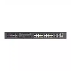
Front Panel of DS-6910/6912/6916UDI
1
3
2
8
9
10
7
6
15
4
Front Panel of DS-6916UDI Figure 2-3

Audio and Video Decoder User Manual
DS-6900UDI Decoder User Manual
5
Description of DS-6916UDI Front Panel Table 2-3
Table 2-4
LED Indicator & Interface
Connections
1
HDD1
Hard disk 1 indicator (Reserved)
2
HDD2
Hard disk 2 indicator (Reserved)
3
POWER
Power indicator
4
LAN
10/100 Mbps Ethernet interface
5
G1
10/100/1000 Mbps Ethernet interface
6
GE1
Local management network interface
7
RS-232 serial interface
Connect to RS-232 devices, e.g., PC etc.
8
USB
USB 2.0 interface
9
GE2
Local management network interface 2
10
G2
10/100/1000 Mbps Ethernet interface 2
Rear Panel 2.2
Rear Panel of DS-6901UDI
Rear Panel of DS-6901UDI Figure 2-4
Description of DS-6901UDI Rear Panel Table 2-5
Interface
Connections
1
LINE IN/OUT
Two-way audio input/output, 3.5mm connector
2
RS-232 serial interface
Connect to RS-232 devices, e.g., PC.

Audio and Video Decoder User Manual
DS-6900UDI Decoder User Manual
6
Rear Panel of DS-6908UDI
Rear Panel of DS-6908UDI Figure 2-5
Description of DS-6908UDI Table 2-6
3
LAN
10/100/1000 Mbps Ethernet interface
4
RS-485 serial interface
Connect to RS-485 devices, e.g., keyboard.
5
Alarm in
8 alarm inputs
Alarm out
8 alarm outputs
6
Power supply
12 VDC power input
7
GND
Interface
Connections
1
Wi-Fi
Reserved
2
Audio output
BNC connector
3
Video output
BNC connector
4
HDMI video output
HDMI output of decoded video
5
DVI video input
DVI input of decoded video
6
VGA video input
VGA input of decoded video
7
LINE IN/OUT
Two-way audio input/output, 3.5mm connector
8
RS-485 serial interface
Connect to RS-485 devices, e.g., keyboard.
9
Alarm in
8 alarm inputs
Alarm out
8 alarm outputs
10
Power
Power indicator

Audio and Video Decoder User Manual
DS-6900UDI Decoder User Manual
7
Rear Panel of DS-6916UDI
Rear Panel of DS-6916UDI Figure 2-6
Description of DS-6916UDI Rear Panel Table 2-7
DS-6910UDI provides 10 HDMI output interfaces, DS-6912UDI provides 12 HDMI output interfaces
and other interfaces are the same with DS-6916UDI.
11
GND
Interface
Connections
1
WiFi
Reserved
2
Audio output
BNC connector
3
Video output
BNC connector
4
HDMI video output
HDMI output of decoded video
5
DVI video input
DVI input of decoded video
6
VGA video input
VGA input of decoded video
7
LINE IN/OUT
Two-way audio input/output, 3.5mm connector
8
RS-485 serial interface
Connect to RS-485 devices, e.g., keyboard, etc.
9
Alarm in
8 alarm inputs
Alarm out
8 alarm outputs
10
Power
Power indicator
11
GND
Audio and Video Decoder User Manual
DS-6900UDI Decoder User Manual
8
Getting Started Chapter 3
Purpose
You are required to activate the decoder first by setting a strong password for it before you can use
the device. And you can configure the basic network parameters.
Activation via Web Browser and Client Software are all supported.
For the first-time user, the default user name of DS-6900UDI is admin, and the default IP address is
192.0.0.64.
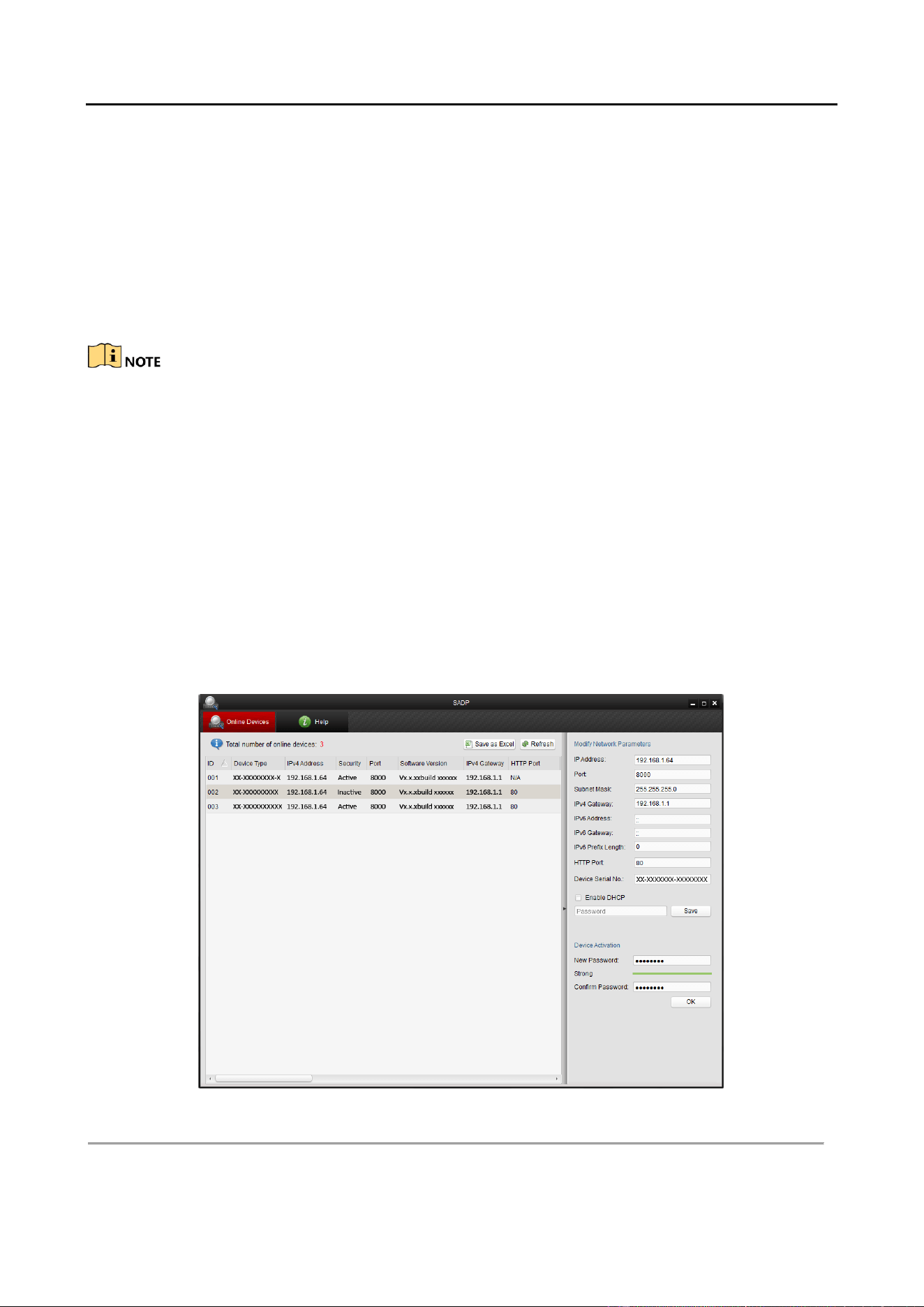
Activation via SADP Software 3.1
SADP software is used for detecting the online device, activating the camera, and resetting the
password.
Get the SADP software from the supplied disk or the official website, and install the SADP
according to the prompts. Follow the steps to activate the camera.
Run the SADP software to search the online devices. Step 1
Check the device status from the device list, and select the inactive device. Step 2
SADP Interface Figure 3-1

Audio and Video Decoder User Manual
DS-6900UDI Decoder User Manual
9
Create a password and input the password in the password field, and confirm the password. Step 3
Click OK to save the password. Step 4
STRONG PASSWORD RECOMMENDED–We highly recommend that you create a strong password
of your own choosing (using a minimum of 8 characters, including upper case letters, lower case
letters, numbers, and special characters) in order to increase the security of your product. And we
recommend that you reset your password regularly, especially in the high security system,
resetting the password monthly or weekly can better protect your product.
You can check whether the activation is completed on the popup window. If activation failed,
please make sure that the password meets the requirement and try again.
Change the device IP address to the same subnet with your computer by either modifying Step 5
the IP address manually or checking the checkbox of Enable DHCP.
Modify the IP Address Figure 3-2
Input the password and click the Save button to activate your IP address modification. Step 6
Activation via Web Browser 3.2
Power on the decoder, and connect the decoder to the network. Step 1
Input the IP address into the address bar of the web browser, and click Enter to enter the Step 2
activation interface.

Audio and Video Decoder User Manual
DS-6900UDI Decoder User Manual
10
Activation Interface Figure 3-3
Create a password and input the password into the password field. Step 3
STRONG PASSWORD RECOMMENDED–We highly recommend that you create a strong password
of your own choosing (using a minimum of 8 characters, including upper case letters, lower case
letters, numbers, and special characters) in order to increase the security of your product. And we
recommend that you reset your password regularly, especially in the high security system,
resetting the password monthly or weekly can better protect your product.
Confirm the password. Step 4
Click OK to save the password and enter the live view interface. Step 5
Activation via Client Software 3.3
The client software is versatile video management software for multiple kinds of devices.
Get the client software from the supplied disk or the official website, and install the software
according to the prompts. Follow the steps to activate the camera.
Run the client software and the Video Wall interface pops up, as shown in the figure below. Step 1

Audio and Video Decoder User Manual
DS-6900UDI Decoder User Manual
11
Control Panel Figure 3-4
Click the Device Management icon to enter the Device Management interface, as shown in Step 2
the figure below.
Control Panel Figure 3-5
Check the device status from the device list, and select an inactive device. Step 3
Click the Activate button to pop up the Activation interface. Step 4
Create a password and input the password in the password field, and confirm the password. Step 5

Audio and Video Decoder User Manual
DS-6900UDI Decoder User Manual
12
STRONG PASSWORD RECOMMENDED–We highly recommend that you create a strong password
of your own choosing (using a minimum of 8 characters, including upper case letters, lower case
letters, numbers, and special characters) in order to increase the security of your product. We
recommend that you reset your password regularly, especially in the high security system,
resetting the password monthly or weekly can better protect your product.
Activation Interface (Client Software) Figure 3-6
Click OK button to start activation. Step 6
Click the Modify Netinfo button to pop up the Network Parameter Modification interface, as Step 7
shown in the figure below.
Modifying the Network Parameters Figure 3-7
Change the device IP address to the same subnet with your computer by either modifying Step 8
the IP address manually or checking the DHCP checkbox.
Input the password to activate your IP address modification. Step 9
Audio and Video Decoder User Manual
DS-6900UDI Decoder User Manual
13
Decoder Configuration and Chapter 4
Operation by Web Browser
You shall acknowledge that the use of the product with the Internet access might be under
network security risks. For avoidance of any network attacks and information leakage, please
strengthen your own protection. If the product does not work properly, contact with your dealer
or the nearest service center.
Purpose
You can configure and operate the device by Web browser or the iVMS-4200 Video Wall Client
Software. In this chapter, the operation and management of the decoder by the Web browser is
provided.
The tested Web browsers include: IE 8.0+, Chrome 18.0+, Firefox 5.0+, and Safari 5.02+.
Open the Web browser and input the IP address of Decoder (e.g., http://192.168.0.0) . Step 1
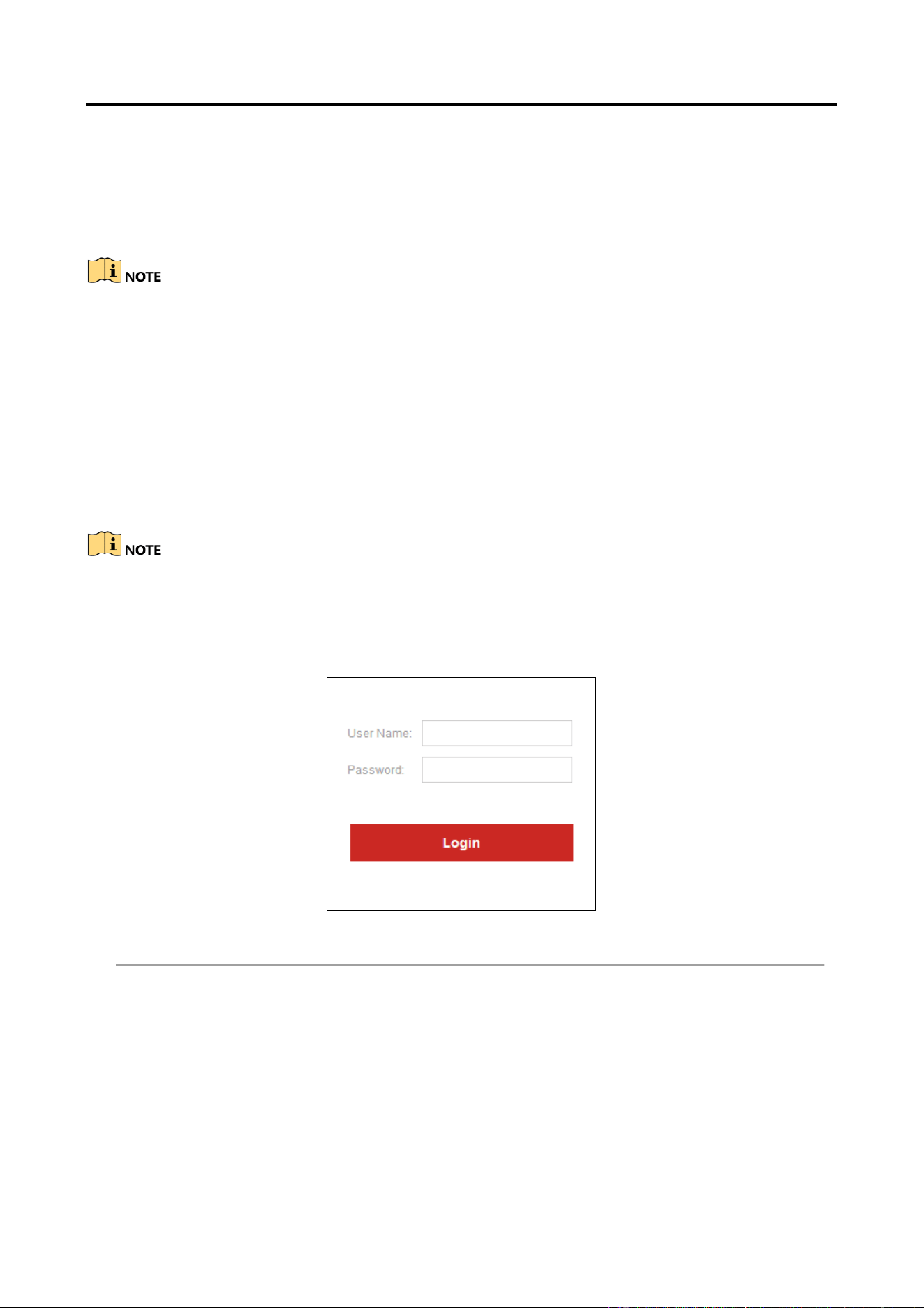
Login to the device. Step 2
Login Interface Figure 4-1
If the device has not been activated, you need to active the device first before login.

Audio and Video Decoder User Manual
DS-6900UDI Decoder User Manual
14
Activation Interface Figure 4-2
1. Set the password for admin user account.
2. Click OK to login the device.
STRONG PASSWORD RECOMMENDED–We highly recommend you create a strong password of
your own choosing (using a minimum of 8 characters, including upper case letters, lower case
letters, numbers, and special characters) in order to increase the security of your product. We
recommend you reset your password regularly, especially in the high security system, resetting the
password monthly or weekly can better protect your product.
If the device is already activated, enter the user name and password in the login interface,
and click the Login button.
The following interface is shown after successful login.
Enter Web Page Figure 4-3

Audio and Video Decoder User Manual
DS-6900UDI Decoder User Manual
15
Decoder Configuration 4.1
Checking Device Information 4.1.1
Purpose
You can check the information of the device in the device information interface, such as the Device
Type, Device Serial No., Firmware Version, Decoding Version, Web Version, Plugin Version etc.
Click Configuration > System > System Settings > Basic Information to view Device Type, Device
Serial No., Firmware Version, DSP Version, etc.
The device name can be edited.
Checking Device Information Figure 4-4
Configuring Time Settings 4.1.2
Purpose
You can set the time for the decoder in the Time Settings interface.
Click Configuration > System Settings > Time Settings to enter the following interface: Step 1

Audio and Video Decoder User Manual
DS-6900UDI Decoder User Manual
16
Configure Time Settings Figure 4-5
Configure the time synchronization by NTP server or manually. Step 2
Configuring Time Sync by NTP Server
A Network Time Protocol (NTP) Server can be configured on your device to ensure the
accuracy of system date/time.
If the device is connected to a Dynamic Host Configuration Protocol (DHCP) network that
has time server properties configured, the camera will synchronize automatically with the
time server.
Enable the NTP function by checking the checkbox, and configure the following settings:
NTP Server: IP address of NTP server.
NTP Port: Port of NTP server.
Configure Time by NTP Figure 4-6
If the device is connected to a public network, you should use a NTP server that has a time
synchronization function, such as the server at the National Time Center (IP Address:
210.72.145.44). If the device is set up in a more customized network, NTP software can be used to
establish a NTP server used for time synchronization.
Configuring Time Synchronization Manually

Audio and Video Decoder User Manual
DS-6900UDI Decoder User Manual
17
Enable the Manual Correction function and then click icon to set the system time
from the pop-up calendar.
Configure Time Manually Figure 4-7
Select the time zone that is closest to the device’s location from the drop-down list. Step 3
Click Save to save the settings. Step 4
Configuring RS-485/RS-232 Serial Port 4.1.3
Configure RS-232 Parameters
Click Configuration > System Settings > RS232 to enter the following interface: Step 1
Configure RS-232 Settings Figure 4-8

Audio and Video Decoder User Manual
DS-6900UDI Decoder User Manual
18
Configure the RS-232 parameters, including the baud rate, data bit, stop bit and parity type. Step 2
Select the Operating Mode of RS-232 as Console or Transparent Channel. Step 3
Console: use the RS-232 serial port for debugging the decoder.
Transparent Channel: use the RS-232 serial port as the transparent channel.
Click Save to save the settings. Step 4
Configure RS-485 Parameters
Click Configuration > System Settings > RS485 to enter the following interface: Step 1
Configure RS-485 Settings Figure 4-9
Configure the RS-485 parameters, including the baud rate, data bit, stop bit and parity type. Step 2
Click Save to save the settings. Step 3
Configuring Basic Network Settings 4.1.4
Purpose
You can set the network parameters for the decoder in the parameter configuration interface.
Click Configuration > Network > TCP/IP to enter the general network settings interface. Step 1

Audio and Video Decoder User Manual
DS-6900UDI Decoder User Manual
19
Configure Basic Network Settings Figure 4-10
Set the network parameters, including the NIC, IP Address, Subnet Mask, Gateway, and DNS Step 2
Server.
The DS-6904/6908/6910/6912/6916UDI provides multiple NICs for selection.
Click Save to save the settings. Step 3
Configuring DDNS Settings 4.1.5
Purpose
If your device is set to use PPPoE as its default network connection, you may set Dynamic DNS
(DDNS) to be used for network access.
Prior registration with your DDNS Provider is required before configuring the system to use DDNS.
Click Configuration > Network > DDNS to enter the DDNS Settings interface: Step 1
Check the Enable DDNS checkbox to enable this feature. Step 2
Select DDNS Type. Five different DDNS types are selectable: IPServer, DynDNS, PeanutHull, Step 3
HiDDNS and NO-IP.
DynDNS
3. Enter Server Address for DynDNS (e.g., members.dyndns.org).
4. Enter the User Name and Password registered in the DynDNS website.
5. In the Domain text field, enter the domain obtained from the DynDNS website.
6. Click Save to save the settings.

Audio and Video Decoder User Manual
DS-6900UDI Decoder User Manual
20
DynDNS Settings Figure 4-11
IPServer
1. Enter server address for IPServer.
2. Click Save to save the settings.
For the IP Server, you have to apply a static IP, subnet mask, gateway and primary DNS from the
ISP. The Server Address should be entered with the static IP address of the PC that runs IP Server
software.
IPServer Settings Figure 4-12
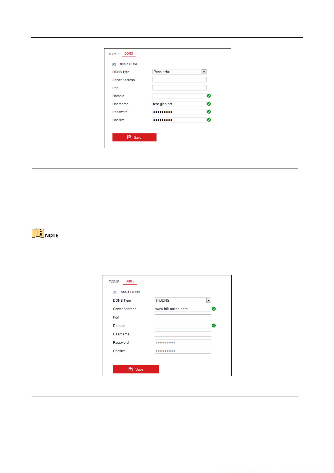
PeanutHull
1. Enter User Name and Password obtained from the PeanutHull website.
2. Click Save to save the settings.
Audio and Video Decoder User Manual
DS-6900UDI Decoder User Manual
21
PeanutHull Settings Figure 4-13
HiDDNS
1. Enter the Server Address of the HiDDNS server: www.hik-online.com.
2. Enter the Domain Name of the device. You can register the alias of the device domain
name in the HiDDNS server first and then enter the alias to the domain name in the
decoder; you can also enter the domain name directly on the decoder to create a new one.
If a new alias of the device domain name is defined in the decoder, it will replace the old one
registered on the server.
3. Click Save to save the settings.
HiDDNS Settings Figure 4-14

Audio and Video Decoder User Manual
DS-6900UDI Decoder User Manual
22
After having successfully registered the device on the HiDDNS server, you can access your device
via Web browser or client software with the Device Domain Name (device name).
Stream Settings 4.1.6
Purpose
The stream configuration refers to the auto stream switch between main stream and sub stream.
Click Configuration > Decoding Configuration > Stream Configuration to enter stream Step 1
configuration interface.
Stream Configuration Interface Figure 4-15
Check the check box of Auto-Switch Stream Type to enable auto switch between main Step 2
stream and sub stream.
Click Save button to save the settings. Step 3
When a screen is split into more than 16 windows, the main stream will automatically switch to
sub stream to lower the bandwidth.
Synchronous Output Settings 4.1.7
Purpose
All video outputs of the device can be configured to be synchronous.
Click Configuration > Decoding Configuration > Synchronous Output Settings to enter the Step 1
synchronous output settings interface.

Audio and Video Decoder User Manual
DS-6900UDI Decoder User Manual
23
Synchronous Output Settings Figure 4-16
Click the Sync Out button to enable the synchronization of all outputs. The following Step 2
message box pops up.
Enable Synchronous Output Figure 4-17
Click OK to confirm the settings. Step 3
Transparent Channel 4.1.8
Purpose
The Transparent Channel refers to the transmission channel used for forwarding data between the
decoder and the encoder without operating on the data.
Click Configuration > Decoding Configuration > Transparent Channel to enter transparent Step 1
channel interface.

Audio and Video Decoder User Manual
DS-6900UDI Decoder User Manual
24
Transparent Channel Interface Figure 4-18
Select a transparent channel from the list to configure. Step 2
Click Modify to modify the parameters of the selected transparent channel. Step 3
Modifying Interface Figure 4-19
Select the Local Serial Port and the Remote Serial Port to RS-485 or RS-232. Step 4
Local Serial Port: the serial port used as the transparent channel by the decoder.
Remote Serial Port: the serial port used as the transparent channel by the encoding device.
You can click Delete to pop up the following dialog box and click OK to delete the selected channel.

Audio and Video Decoder User Manual
DS-6900UDI Decoder User Manual
25
Managing User Account 4.1.9
The user accounts can be managed in this interface.
Click Configuration > System > User Management to enter the account management Step 1
interface.
Configure User Account Figure 4-20
You can add, modify or delete the user account, as well as configure operating permissions Step 2
for each user account.
Add User Account and Set Permission Figure 4-21
For the admin user, only the password can be modified.
Audio and Video Decoder User Manual
DS-6900UDI Decoder User Manual
26
STRONG PASSWORD RECOMMENDED–We highly recommend that you create a strong password
of your own choosing (using a minimum of 8 characters, including upper case letters, lower case
letters, numbers, and special characters) in order to increase the security of your product. We
recommend that you reset your password regularly, especially in the high security system,
resetting the password monthly or weekly can better protect your product.
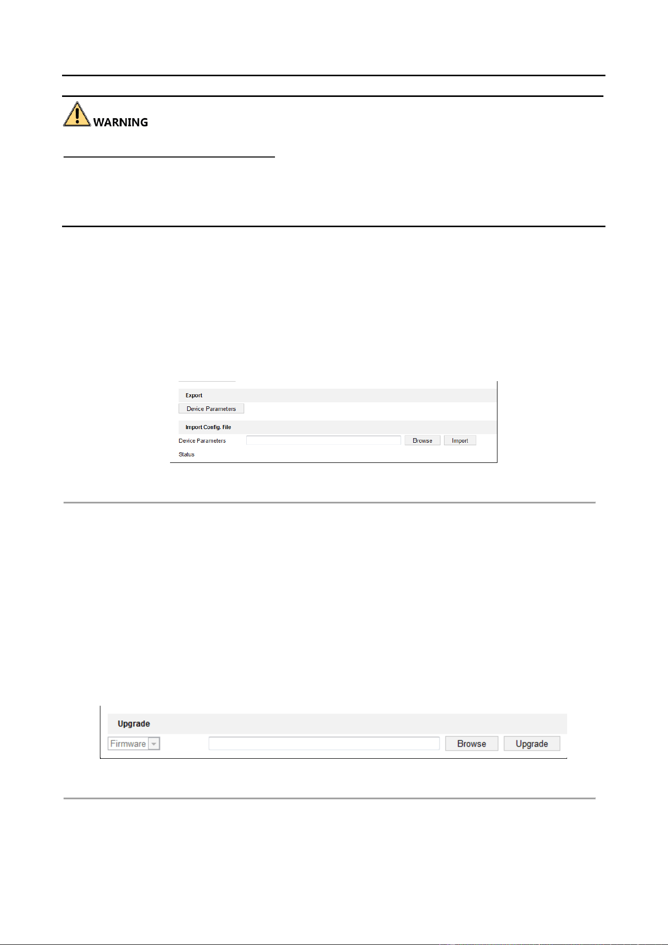
Importing/Exporting Configuration Files 4.1.10
Purpose
The configuration files of the device can be imported from or exported to local device for backup,
which maintains convenient parameters configuration.
Click Configuration > System > Maintenance to enter the parameters import/export Step 1
interface:
Import/Export Configuration File Figure 4-22
Click Browse to select the file from the local directory and then click the Import button to Step 2
import a configuration file. Click Device Parameters to export parameters.
Maintenance 4.1.11
Click Configuration > System > Maintenance to perform Reboot, Upgrade, and Default operations .
Upgrading the Device
Click Browse to search the upgrading files. Step 1
Click Upgrade to upgrade it. Step 2
Device Management Figure 4-23
Audio and Video Decoder User Manual
DS-6900UDI Decoder User Manual
27
When logging in the device for first time, please install the plug-in according to the
prompt on the screen.
The device will restart after completing the upgrade.
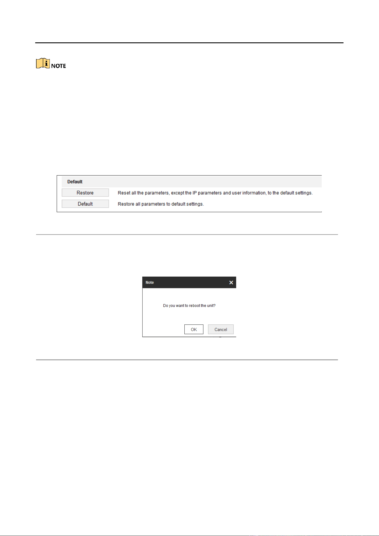
Restoring the Default Settings
Click Default to restore the completed factory settings of the decoder.
Or
Click Restore to restore a part of the factory settings of the decoder.
Default Settings Figure 4-24
Rebooting the Device:
Click Reboot to reboot the device.
Reboot the Device Figure 4-25

Audio and Video Decoder User Manual
DS-6900UDI Decoder User Manual
28
Setting Video Wall Layout 4.2
Purpose
To realize the display of the decoded video on the video wall, you must set the Video Wall
Configuration in the first place so as to link the video output with video wall.
Click Video Wall Configuration to enter the corresponding interface. Step 1
Enter Video Wall Configuration Interface Figure 4-26
You can use the default video wall layout or click to add a new layout. Enter the number Step 2
of screens in row and column and up to 16 × 20 split screens are available.
Split Screen Configuration Figure 4-27
Click OK to finish the adding of the video wall information. Step 3
Click and drag the output channels from the left-side list to the display screen. Step 4
Move the cursor to the window, and icon automatically appears in the upper-right comer Step 5
of the window. Click to close the window.

Audio and Video Decoder User Manual
DS-6900UDI Decoder User Manual
29
Delete the Window Figure 4-28
Decoding Output Configuration 4.3
Purpose
Decoding Output Configuration includes resolution configuration and output mode configuration.
Click Video Wall Configuration to enter the corresponding interface. Step 1
Decoding Output Figure 4-29
In the output list, there are two kinds of video output signals, respectively BNC and HDMI. Step 2
Right click one of BNC signal sources and select Resolution Configuration to pop up the
interface as Figure 4.30.
Resolution Configuration Figure 4-30
Audio and Video Decoder User Manual
DS-6900UDI Decoder User Manual
30
Choose one of the resolutions from the drop down list. Check the checkbox of Batch Step 3
Configuration to set the same configuration for other outputs with same signal source.
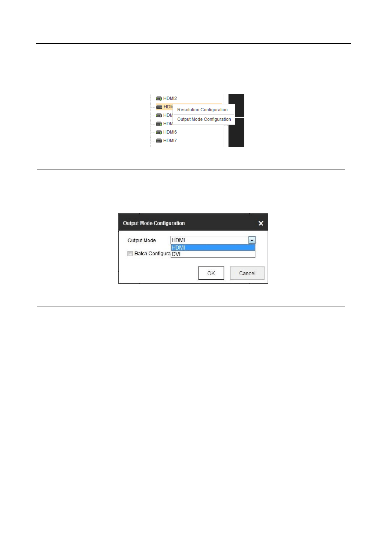
Right click one of the HDMI signal sources. Step 4
Decoding Output Configuration Figure 4-31
Select Output Mode Configuration to pop up the interface as Figure 4.32. The output mode Step 5
is with HDMI and DVI available. Check the checkbox of Batch Configuration to set the same
configuration for other HDMI outputs.
Output Mode Configuration Figure 4-32
Decoding Operation 4.4
Purpose
After configuration has done according to 4.2 Setting Video Wall Layout, the decoding video on
the video wall can be realized in this section.
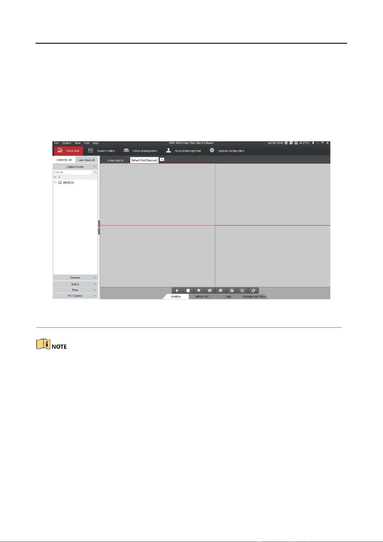
Click Video Wall to enter video wall interface. Step 1

Audio and Video Decoder User Manual
DS-6900UDI Decoder User Manual
31
Video Wall Interface Figure 4-33
Description of Video Wall Table 4-1
No.
Description
1
Camera: the camera added in the Web
2
Scene: the Web supports up to 8 scenes by default, capable
of independent scene configuration and fast switching
3
TV Wall: TV Wall operation interface
4
Shortcut toolbar: decoding screen layout, save the scene,
delete all windows, refresh all windows, at bottom
Adding a Encoding Device 4.4.2
Click Add to add new encoding devices. Step 1
Encoding Device List Figure 4-34

Audio and Video Decoder User Manual
DS-6900UDI Decoder User Manual
32
Input Device Name, IP Address, Port, Password, Area Name and Channel Number. Check Step 2
the checkbox of Get Stream by Stream Media to lower the network load of the device.
Add Camera Interface Figure 4-35
Select one of the areas or one channel of the encoding device, and click Modify to modify Step 3
corresponding parameters.
Modify Area Figure 4-36

Audio and Video Decoder User Manual
DS-6900UDI Decoder User Manual
33
Modify Encoding Device Figure 4-37
Select one area or one channel of encoding device and click Delete to delete the encoding Step 4
device.
Delete Camera Interface Figure 4-38
Decoding on the Video Wall 4.4.3
Drag the channel from the left side list to realize the decoding in the selected window. Step 1
Decode the Video on the Wall Figure 4-39

Audio and Video Decoder User Manual
DS-6900UDI Decoder User Manual
34
Select one decoding window and click to set the decoding screen layout with Step 2
1/4/6/8/9/12/16/25/36 split screen available.
Split Screen Interface Figure 4-40
Right click the selected window and the following interface shows up. Step 3
Decoding Channel Interface Figure 4-41
Stop Decoding: stop decoding
Decoding Status: check the decoding status.

Audio and Video Decoder User Manual
DS-6900UDI Decoder User Manual
35
Decoding Channel Status Figure 4-42
Click More to check the decoding information of each channel.
Checking More Decoding Status Figure 4-43
Turn on Audio: enable the audio in the corresponding window.
Decoding Delay: choose the type of decoding delay. The default mode is the same with medium
real time and fluency.
Decoding Delay Figure 4-44
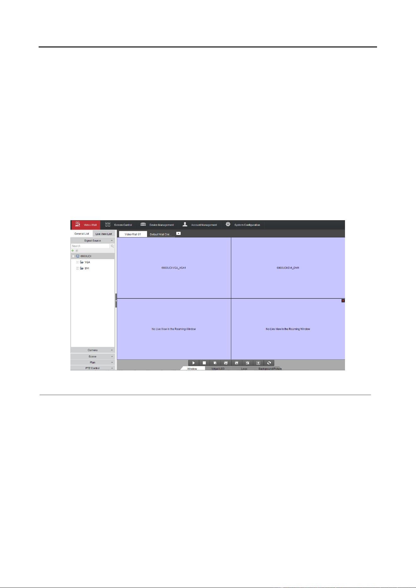
Video Wall Roaming 4.4.4
Drag one camera from the left side list to the video wall layout to enable decoding in the Step 1
corresponding window automatically.
Drag the decoding window randomly to realize the window roaming on the Video Wall. Step 2

Audio and Video Decoder User Manual
DS-6900UDI Decoder User Manual
36
Video Wall Roaming Interface Figure 4-45
Select one of the roaming windows, and click to realize split screen in the selected Step 3
roaming window with 1/4/6/8/9/16/25/36 available.
Generally the selected window is at top by default. Click to place the selected window at Step 4
bottom.
Roaming and fluent video cannot be realized in the window with the signal outputted via BNC
interfaces.
Setting Scene 4.4.5
Purpose
Different video wall layouts are saved as different scenes and up to 8 scenes can be added. You can
easily view the required live videos on the video wall by calling the scene.
In the Video Wall interface drag the channel from the left side list to realize the decoding in Step 1
the selected window.
Saving the Scene Interface Figure 4-46

Audio and Video Decoder User Manual
DS-6900UDI Decoder User Manual
37
Click Save to save the scene directly and click Save as to pop up the following dialog box. Step 2
Save as Interface Figure 4-47
Input the Name and click OK to save the scene. Step 3
Scene List Figure 4-48
Select one of the scenes you have configured. Click to call the scene. Step 4
You can also click to rename the scene, or click to delete the scene.
Audio and Video Decoder User Manual
DS-6900UDI Decoder User Manual
38
Decoder Configuration and Chapter 5
Operation by Client Software
Run the disk of iVMS-4200 Video Wall Client Software, and double click the icon to install it in your
PC. In this chapter, the basic procedure of operating the decoder by the software is described.
The following figure shows the main interface after accessing to the software:
Main Interface Figure 5-1
The software is capable of many functions for controlling and managing many devices. In this
manual, only the operation related to the decoder is introduced.
Adding an Encoding/Decoding Device 5.1
Click Device Management tab to enter the Device Management interface. Step 1

Audio and Video Decoder User Manual
DS-6900UDI Decoder User Manual
39
Device Management Interface Figure 5-2
Click the Add Device and you can add device manually by means of IP address/domain, IP Step 2
segment and HiDDNS.
Add Device by IP/Domain Figure 5-3
You can add the device by detecting the online devices. The active online decoding devices Step 3
in the same local subnet with the software are displayed on the list. Select the decoder and
click Add to Client to add the decoder.

Audio and Video Decoder User Manual
DS-6900UDI Decoder User Manual
40
Add Device by Detecting the Online Device Figure 5-4
The successfully added encoding/decoding device can be viewed in the list.
List of Added Decoders Figure 5-5
Configuring Video Wall Settings 5.2
Configuring Video Wall Layout 5.2.1
Adding a Video Wall Layout
Click Video Wall tab to enter the Video Wall setting interface. Step 1

Audio and Video Decoder User Manual
DS-6900UDI Decoder User Manual
41
Video Wall Layout Settings Figure 5-6
You can use the default video wall layout or click and select Add Video Wall to a new Step 2
video wall layout.
Add Screen Information Figure 5-7
You can modify the default video wall, but not allowed to delete it.

Audio and Video Decoder User Manual
DS-6900UDI Decoder User Manual
42
Add Video Wall Figure 5-8
Edit the video wall name, and the number of screens in row and column. Step 3
Click Add to finish video wall adding. Step 4
Up to 5 video walls can be added to the client software.
The total number of display windows of the video wall is 16 × 20.
The range of the row number is between 1 and 16, and column number between 1 and
20.
Click and drag the output channels from the left-side list to the display window on the right. Step 5

Audio and Video Decoder User Manual
DS-6900UDI Decoder User Manual
43
Link Decoding Output to Video Wall Window Figure 5-9
You can select a linked display window and click Cancel to release the linkage, or click Cancel All to
release all the linked windows.
Modifying a Video Wall Layout
Choose Modify Video Wall to edit current video wall’s layout, name and decoding outputs
Modify Video Wall Figure 5-10

Audio and Video Decoder User Manual
DS-6900UDI Decoder User Manual
44
Deleting a Video Wall Layout
Choose Delete Video Wall and the information dialog box pops up. Click OK to delete the selected
video wall.
Delete Video Wall Figure 5-11
Modifying the Decoding Output 5.2.2
In the Add/Modify Video Wall interface, select a decoding output and click the to edit the Step 1
video output parameters.
Add/Modify Video Wall Interface Figure 5-12
Select the resolution from the drop-down list. Step 2
Edit the width and height (pixel) of LED display when the LED is connected. Step 3

Audio and Video Decoder User Manual
DS-6900UDI Decoder User Manual
45
Modify Decoder Output Figure 5-13
The value of LED width and height cannot exceed the resolution you selected.
The supported min. value of LED width and height is 288*288.
When the value of LED width or height is set to 0, the LED resolution is not enabled.
Displaying Video on Video Wall 5.3
Purpose
After the settings of the encoding device, decoding device and video wall, the video stream from
the encoding devices can be decoded and displayed on the Video Wall.
After enable decoding and displaying, the captured picture of the video from the encoding device
displays on the Video Wall interface. And the real-time live view is shown on the physical video
wall.
Decoding and Displaying Video 5.3.1
Enter the Video Wall interface. Step 1

Audio and Video Decoder User Manual
DS-6900UDI Decoder User Manual
46
Video Wall Operation Page Figure 5-14
Click scene to display the scene interface. Click to add a new scene, click to edit the Step 2
name for the scene, and click to delete the scene.
Up to 8 scenes can be added.
Video Wall Operation Page Figure 5-15
Click and drag the camera from the left side list to the display window of video wall. The Step 3
video stream from the camera will be decoded and displayed on the Video Wall.
You can select a decoding window and then double click a camera to decode and display the
video. You can also click and hold the Ctrl or Shift key to select multiple cameras and then
drag them to the video wall.

Audio and Video Decoder User Manual
DS-6900UDI Decoder User Manual
47
You can move the cursor to the preview window and click in the lower-left corner to stop
decoding.
Select a decoding window and click to set the split screen with 1/4/6/8/9/12/16/25/36 Step 4
available.
If the decoded camera supports PTZ control, you can click beside PTZ to activate the PTZ Step 5
control panel.
PTZ Interface Figure 5-16
Right-click on a playing window to activate the decoding management menu, as shown Step 6
below:
The menu differs depending on the devices.
Right-click Menu Figure 5-17
Audio and Video Decoder User Manual
DS-6900UDI Decoder User Manual
48
Stop/Start Decoding: stop/start the decoding.
Start/Stop Live View: stop/start the live view of the decoded video.
Start/Pause Successive Decoding: start/pause the cycle decoding. This function is only
supported by decoder.
Enable Audio: turn on/off the audio of the decoding video.
Decoding Status: view the status of the decoding channel, like decoding status and stream
type.
Stick at Bottom: generally the selected window is at top by default. Click Stick at Bottom to
place the selected window at bottom.
Lock/Unlock: the locked decoding window is unable to do any operation.
Set Alarm Window: display the video triggered by event or alarm input on Video Wall.
Screen Control: enter the screen control when the RSC server is added. Please refer to
Chapter 5.5 for details.
Video Wall Display Figure 5-18
Audio and Video Decoder User Manual
DS-6900UDI Decoder User Manual
49
Decoding Toolbar Table 5-1
Icon
Description
Start Decoding
Stop Decoding
Stop All Window
Enable All VCA Decoding
Disable All VCA Decoding
Open Roaming Window
Open the Window via Coordinate
Refresh
The bottom bar lists several functions, but the decoder only supports Window and Log, since the
iVMS-4200 Video Client Software is not only available for decoder but also for other devices.
Configuring Playback 5.3.2
Purpose
The video file is supported to be played back on the video wall.
Playback function is only supported by decoder.
Click and drag the camera on the left-side list to the display window of video wall, or you can Step 1
open a window if supported.
Click Window at the bottom to unfold more configuration and operation toolbar. Step 2
Click Start Playback to start searching the video files of the camera. Step 3

Audio and Video Decoder User Manual
DS-6900UDI Decoder User Manual
50
Figure 5-19
If the record file is of current day, the video file can be played back automatically. If not, you Step 4
can set the search condition on the search panel (click to show the date and click More
Search Conditions to specify more conditions), and click Search to find the video file.
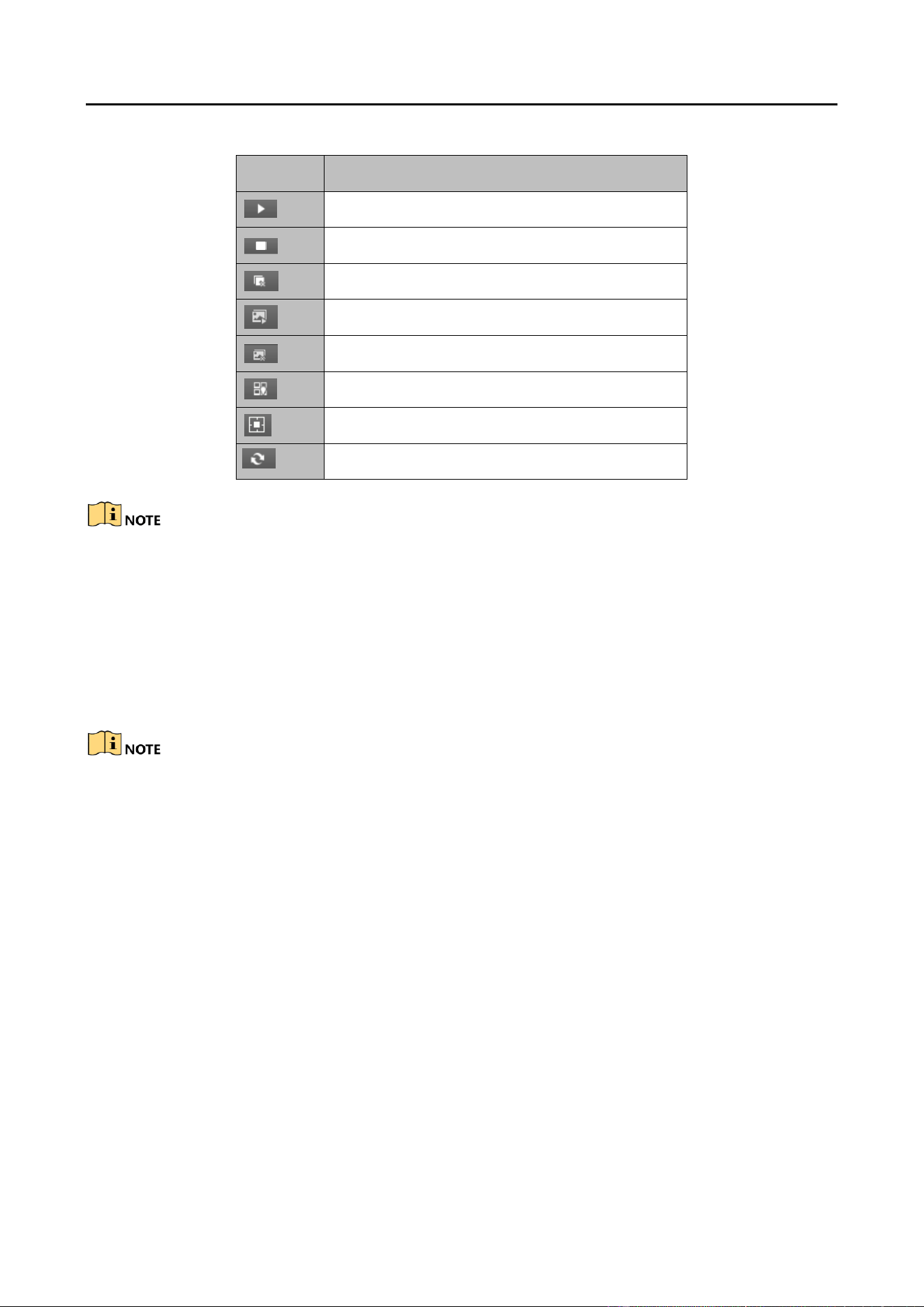
The following icons are available for controlling the playback
Playback Toolbar Table 5-2
Icon
Function
Pause/Start the playback
Delete View
Slow Forward
Fast Forward
Start/Stop Clipping
Capture
Configuring Cycle Decoding 5.3.3
Purpose:
Audio and Video Decoder User Manual
DS-6900UDI Decoder User Manual
51
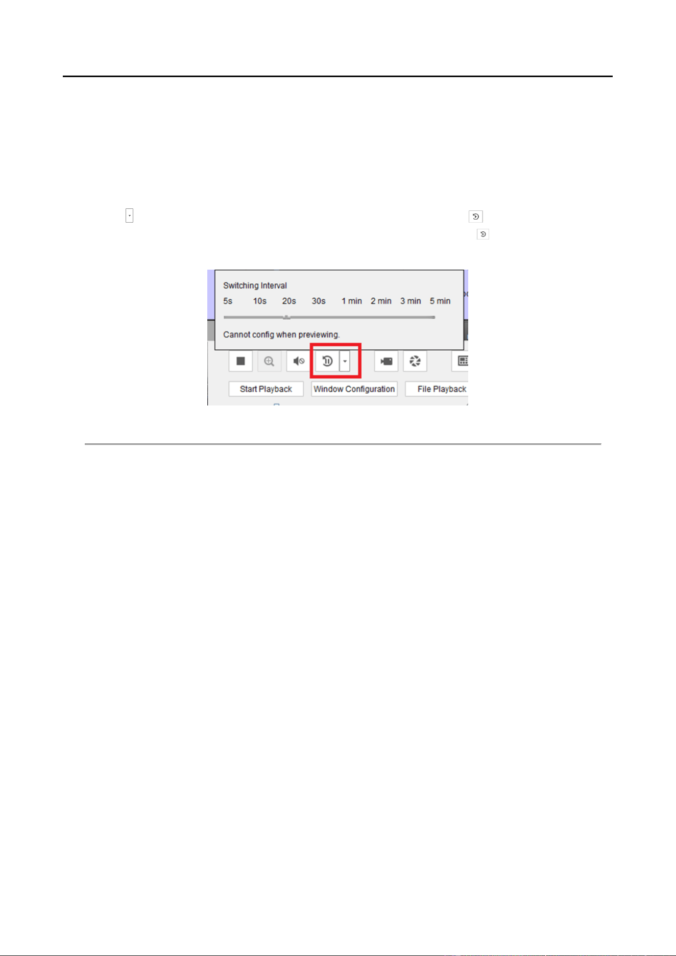
Cycle decoding refers to you can configure multiple video streams in a video output and the
interval time in switching video streams.
Click and drag the camera from the left-side list to the display window of video wall, or you Step 1
can open a window if supported.
Click and drag a group to the window. Step 2
Click to set the switching interval for the cycle decoding and click to start decoding. You Step 3
can view the cycle decoding on the physical video wall. You can click to stop cycle
decoding.
Cycle Decoding Figure 5-20
Window Configuration 5.3.4
Purpose:
You can set the window as the alarm window to display the video triggered by event or alarm input
on the video wall, you can also set the decoding delay and image parameters.
Click and drag the camera from the left-side list to the display window of the video wall, or Step 1
you can open a window if supported.
Click Window Configuration to pop up the configuration dialog box. Step 2

Audio and Video Decoder User Manual
DS-6900UDI Decoder User Manual
52
Window Configuration Figure 5-21
Configure the parameters as needed. The window status shows the current status of the Step 3
selected window.
Alarm Window: display the video triggered by the event or alarm input on the selected −
window of the video wall.
Decoding Delay: set the delay status of the decoding according to the actual needs. −
Functions like Fluent Video, Smart Decoding, 3D DNR, Defog, and Low Illumination are not
supported by DS-6900UDI.
Remote Screen Control 5.4
Purpose
Installed with the RSC Server, it allows you to show your PC screen on the Video Wall. Perform the
following procedure to configure the RSC server and get your screen shown on the Video Wall.
Configuring the RSC Server 5.4.1
Install the RSE Server, which enables the PC screen to be displayed on the Video Wall, and Step 1
double-click to run it.

Audio and Video Decoder User Manual
DS-6900UDI Decoder User Manual
53
Run the RSC Server Figure 5-22
You can click the Status to check the server information, including the IP address, name, port, Step 2
password of the server, and the connected device number.
Click the Settings to check the directory of saving the program files, enable or disable the Step 3
feature of Auto-Run when OS starts, and select the language (Chinese/English).
Local Configuration of RSC Server Figure 5-23
Remote Screen Control via RSC Server 5.4.2
Enter the Video Wall page and click in the Camera list area, or click to add it Step 1
on Device Management page, to add the RSC server.

Audio and Video Decoder User Manual
DS-6900UDI Decoder User Manual
54
Add RSC Server Figure 5-24
Enter the parameters to add the RSC server. Please refer to Chapter 5.1 Adding an Step 2
Encoding/Decoding Device to add the RSC server.
The default user name is admin and the server password is 12345 and we highly recommend you
to change the default password to avoid the security problem.
The successfully added RSC server is listed in the camera list. Step 3
Add RSC Server Figure 5-25
On the camera list, click and drag the RSC server to the video output window. Step 4

Audio and Video Decoder User Manual
DS-6900UDI Decoder User Manual
55
Link RSC to Video Wall Figure 5-26
Right click on the window and select Screen Control to remotely control the signal source. Step 5
The RSC server supports the screen control for 1-channel video output only.
Right-click Menu Figure 5-27
You can use the toolbar on the window’s upper right corner to realize the operations for Step 6
image, video, PPT and remark.

Audio and Video Decoder User Manual
DS-6900UDI Decoder User Manual
56
Screen Control Interface Figure 5-28
Click to display all the image files in the directory set in the RSC Sever.
Screen Control Interface (1) Figure 5-29
Click to display all the video files in the directory set in the RSC Sever.
Screen Control Interface (2) Figure 5-30
Click to display all the PPT files in the directory set in the RSC Sever.

Audio and Video Decoder User Manual
DS-6900UDI Decoder User Manual
57
Screen Control Interface (3) Figure 5-31
Click to pop up the following remark tool bar.
Remark Tool Bar Figure 5-32
Remote Configuration 5.5
Purpose
In the remote configuration interface, you can configure the parameters of the added device,
including the system, network, event, etc.
On the Device Management interface, click to select an added device from the list and click Step 1
Remote Configuration to enter Remote Configuration interface.
Audio and Video Decoder User Manual
DS-6900UDI Decoder User Manual
58
Remote Configuration Figure 5-33
Configure the system parameters, network parameters and event parameters on the Step 2
Remote Configuration.
Configuring Multi-Port Link Aggregation 5.6
Purpose
The Multi-Port Aggregation (Ethernet Channel) is port link aggregation technology or port-channel
architecture used for the connection between the switches.
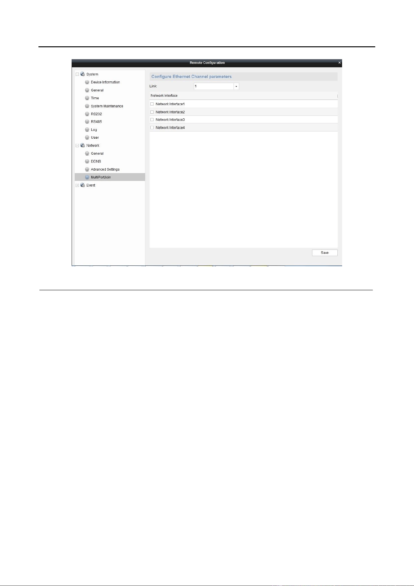
Click Remote Configuration>Network>MultiPortJoin to enter the Multi-Port Aggregation Step 1
Settings interface.
Select a link number from the list. Step 2
Check the checkbox to select the network interfaces to form a channel-group link, which can Step 3
effectively enhance the link transmission bandwidth.

Audio and Video Decoder User Manual
DS-6900UDI Decoder User Manual
59
Multi-port Joint SettingsFigure 5-34
The port link aggregation is not supported by DS-6901UDI.
The switch connected to DS-6900UDI must be configured with the port link aggregation
as well.
Two adjacent network interfaces cannot be selected to form a link. Example, you can
select Network Interface 1 and Network Interface 3, or Network Interface 2 and Network
Interface 4.
The network interface 1 corresponds to the GE1 interface, network interface 2 to G1,
network interface 3 to GE2, and network interface 3 to G2 on the rear panel.
The G1 and G2 can be used as 2G switch when the network interface 2 and network
interface 4 are configured in port link aggregation.

Audio and Video Decoder User Manual
DS-6900UDI Decoder User Manual
60
Display via Wi-Fi Connection Chapter 6
Purpose
With the Wi-Fi module connected, the DS-6900UDI supports displaying the signal from mobile
phone or pad via AirPlay (ISO) or DLNA (Android) to the video wall or other display units.
Insert the Wi-Fi module to the DVI video input connector on the rear panel of the device. Step 1
Use your phone or pad to search and connect the Wi-Fi network (default ID: DIRECT-TV-Step 2
DONGLE-XXXXXX, default password: 12345678 )
Open the browser of your phone or pad and input https: //192.168.211.161 in the address Step 3
field to enter the settings page.
Settings PageFigure 6-1
Configure the HDMI Dongle parameters, including the Name, Hotspot Password, Device Step 4
Display Output and the Soft-Ap Frequency.
The Soft-Ap Frequency parameter must be consistent to the phone or pad performance.
Turn on the AirPlay (ISO) or DLNA (Android) to start playing the signal from the phone to the Step 5
connected display unit. Please refer to the user manual of your phone for the details of
AirPlay or DLNA instructions.

Audio and Video Decoder User Manual
DS-6900UDI Decoder User Manual
61
Appendix Chapter 7
Specifications 7.1
DS-6901/6904/6908 UDI Specification Table 7-1
Model
DS-6901UDI
DS-6904UDI
DS-6908UDI
Video/Audio
Output
VGA and DVI-I
Input
/
WSXGA: 1680×1050@60Hz
WXGA: 1440×900@60Hz
WXGA:1280×800@60Hz,
1366×768@60Hz,
1080p: 1920 × 1080@50/60Hz
1080I: 1920 × 1080@50/60Hz
UXGA: 1600 × 1200@60Hz
XVGA: 1280 × 960@60Hz
720p: 1280 × 720@50Hz/60Hz
SXGA: 1280 × 1024@60Hz
XGA: 1024 × 768@60Hz
Video/Audio
Output
HDMI Output
1-ch
4-ch
8-ch
4K: 3840 × 2160@30Hz ( for even interface only)
1080p: 1920 × 1080@50/60Hz
WSXGA: 1680×1050@60Hz
UXGA: 1600 × 1200@60Hz (for even interface only)
720p: 1280 × 720@50Hz/60Hz
SXGA: 1280 × 1024@60Hz
XGA: 1024 × 768@60Hz
VGA Output
1-ch
/
/
1080p: 1920 × 1080@50/60Hz
WSXGA: 1680×1050@60Hz
SXGA: 1280 × 1024@60Hz
720p: 1280 × 720@50Hz/60Hz
XGA: 1024 × 768@60Hz
BNC Output
1-ch
2-ch, 1 DB 15
4-ch, 1 DB 15
Audio/
Video
Decoding
Decoding
Resolution
Up to 12MP
Decoding Channel
16-ch
32-ch
64-ch

Audio and Video Decoder User Manual
DS-6900UDI Decoder User Manual
62
Decoding
Capability
12MP@20fps: 2-
ch
8MP@30fps: 4-ch
5MP@30fps: 6-ch
3MP@30fps: 10-
ch
1080p@30fps: 16-
ch
12MP@20fps:4-ch
8MP@30fps: 8-ch
5MP@30fps: 12-ch
3MP@30fps: 20-ch
1080p@30fps: 32-
ch
12MP@20fps:8-ch
8MP@30fps: 16-
ch
5MP@30fps: 24-
ch
3MP@30fps: 40-
ch
1080p@30fps: 64-
ch
Split Screen
1/4/6/8/9/12/16
1/4/6/8/9/12/16/2
5
1/4/6/8/9/12/16/
25/36
External
Interface
Network Interface
1; 10/100/1000
Mbps self-
adaptive Ethernet
interface
2; 10/100/1000 Mbps self-adaptive
management network interface
2; 10/100/1000 Mbps self-adaptive
Ethernet interface
16; 10M/100Mbps self-adaptive
Ethernet interface
Serial Interface
1 RS-232 (RJ 45), 1 RS-485
Two-Way Audio In
1-ch, 3.5 mm connector (2.0 Vp-p, 1 k Ω)
Two-Way Audio
Out
1-ch, 3.5 mm connector (2.0 Vp-p, 1 k Ω)
Audio Output
1-ch
4-ch, 1 DB 15
8-ch, 1 DB 15
Alarm In
8-ch
Alarm Out
8-ch
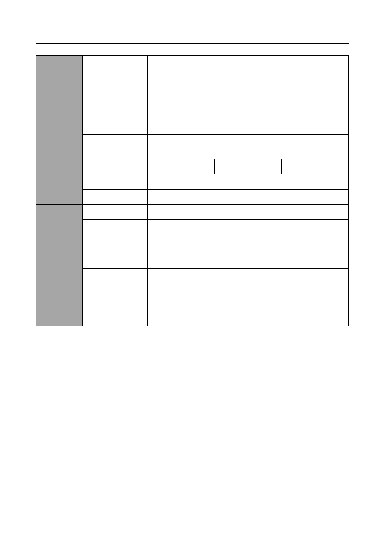
General
Power Supply
12 VDC
100 to 240 VAC
Power
Consumption
≤ 15 W
≤ 70 W
Working
Temperature
-10° C to 55° C (14° F to 131° F)
Working Humidity
10% to 90%
Dimensions
(W × D × H)
220 × 148 × 45
mm (8.66" × 5.83"
× 1.77")
440 × 311 × 44.5 mm (17.32" × 12.24" ×
1.75")
Weight
≤ 1.2 kg (2.65 lb)
≤ 5.2 kg (11.4 lb)

Audio and Video Decoder User Manual
DS-6900UDI Decoder User Manual
63
DS-6910/6912/6916 UDI Specification Table 7-2
Model
DS-6910UDI
DS-6912UDI
DS-6916UDI
Video/Audi
o Output
VGA and DVI-I
Input
WSXGA: 1680×1050@60Hz
WXGA: 1440×900@60Hz
WXGA: 1280×800@60Hz, 1366×768@60Hz,
1080p: 1920 × 1080@50/60Hz
1080I: 1920 × 1080@50/60Hz
UXGA: 1600 × 1200@60Hz
XVGA: 1280 × 960@60Hz
720p: 1280 × 720@50Hz/60Hz
SXGA: 1280 × 1024@60Hz
XGA: 1024 × 768@60Hz
Video/Audi
o Output
HDMI Output
10-ch
12-ch
16-ch
4K: 3840 × 2160@30Hz ( for even interface only)
1080p: 1920 × 1080@50/60Hz
WSXGA: 1680×1050@60Hz
UXGA: 1600 × 1200@60Hz (for even interface only)
720p: 1280 × 720@50Hz/60Hz
SXGA: 1280 × 1024@60Hz
XGA: 1024 × 768@60Hz
BNC Output
5-ch, 2 DB 15
6-ch, 2 DB 15
8-ch, 2 DB 15
Audio/
Video
Decoding
Decoding
Resolution
Up to 12MP
Decoding Channel
80-ch
96-ch
128-ch
Decoding
Capability
12MP@20fps: 10-
ch
8MP@30fps: 20-
ch
5MP@30fps: 30-
ch
3MP@30fps: 50-
ch
1080p@30fps: 80-
ch
12MP@20fps: 12-
ch
8MP@30fps: 24-
ch
5MP@30fps: 36-
ch
3MP@30fps: 60-
ch
1080p@30fps: 96-
ch
12MP@20fps:16-
ch
8MP@30fps: 32-
ch
5MP@30fps: 48-
ch
3MP@30fps: 80-
ch
1080p@30fps:
128-ch
Split Screen
1/4/6/8/9/12/16/25/36
Audio and Video Decoder User Manual
DS-6900UDI Decoder User Manual
64
External
Interface
Network Interface
2; 10/100/1000 Mbps self-adaptive management network
interface
2; 10/100/1000 Mbps self-adaptive Ethernet interface
16; 10M/100 Mbps self-adaptive Ethernet interface
Serial Interface
1 RS-232 (RJ 45), 1 RS-485
Two-Way Audio In
1-ch, 3.5 mm connector (2.0 Vp-p, 1 k Ω)
Two-Way Audio
Out
1-ch, 3.5 mm connector (2.0 Vp-p, 1 k Ω)
Audio Output
10-ch, 2 DB 15
12-ch, 2DB 15
16-ch, 2 DB 15
Alarm Input
8
Alarm Out
8
General
Power Supply
100 to 240 VAC
Power
Consumption
≤ 108 W
Working
Temperature
-10° C to +55° C (+14° F to +131° F)
Working Humidity
10% to 90%
Dimensions
(W × D × H)
440 × 311 × 80 mm (17.32" × 12.24" × 3.15")
Weight
≤ 6.4 kg (14.11 lb)

Audio and Video Decoder User Manual
DS-6900UDI Decoder User Manual
65
FAQ 7.2
Why cannot ping the decoder?
Check the cable and the switch. −
Please refer to Chapter 3 to configure the IP address of the decoder. −
Why cannot connect the decoder with client software?
Check the decoder IP address. −
Cable is connected. −
User name and password of decoder are correct. −
Why cannot play back the record files in DVR with decoder?
Check the DVR network connection. −
Check the parameters of the playback file. −
Check if there are files existed in the selected time duration. −
Why cannot decode the stream transported by stream media server?
Check the network connection between decoder and stream media server. −
Check if the stream media server port is connected with the port added on decoder. −

Audio and Video Decoder User Manual
DS-6900UDI Decoder User Manual
66
List of Third-party IP Cameras Access 7.3
IP Camera
Manufacturer
Model
Supported Video
Format
Panasonic
SP306H
H.265+. H.265, H.264,
H.264+, MJPEG, MPEG4,
SP336H
Sony
SNC-CH220
SNC-RH124
Axis
P5532
Q7404
Sanyo
VCC-HD2500P
SAMSUNG
SND-5080P
Bosch
NBC265P
Zavio
D5110
Arecont
AC1305M
Pelco
IX30DN-ACFZHB3
Onvif
Supported