Loading ...
Loading ...
Loading ...
Power Quality Logger
Safety Instructions
9
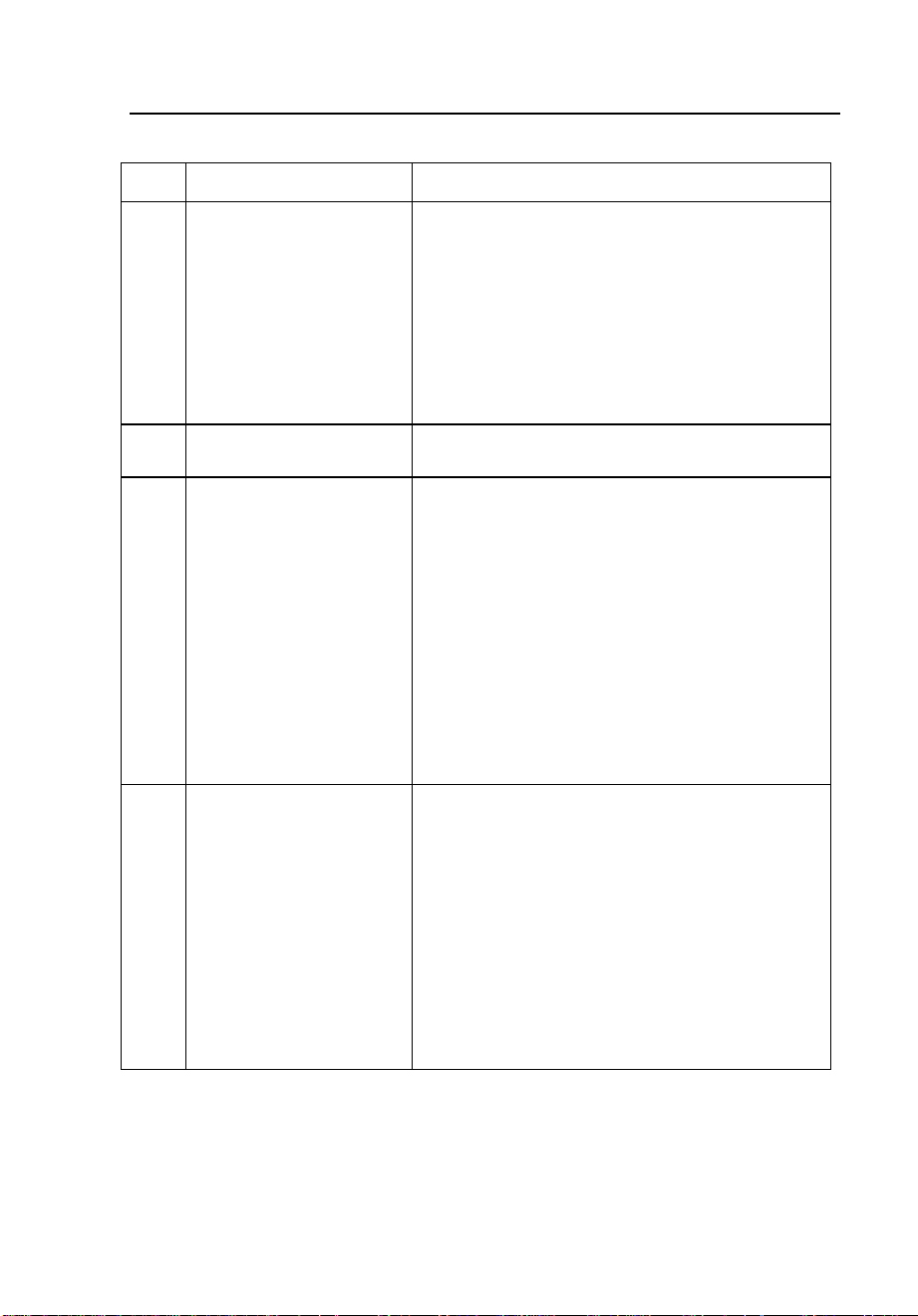
Table 4. 1745 Power Quality Logger - Controls and Indicators
Item Name Description
1
Connector for
Logger power
supply.
This is where the power cord attaches to the
Logger. The power cord connects in parallel
to any two test leads as long as the voltage
is below 660 V absolute maximum.
Whenever there is any risk that voltage
could be higher, connect the power cord to a
wall outlet using the appropriate
international power plug (supplied).
Power supply voltage range: 88-660 V AC or
100-350 VDC, 50 Hz / 60 Hz, 600 V CAT III.
2
START/STOP switch The START/STOP button is used to start or
end switch-operated logging sessions.
3
LCD status display Shows measured input values to provide
confidence in proper setup and test lead
connections. Every 3 seconds, the display
changes to the next set of readings in the
following sequence:
1. The three voltage levels
2. The main three phase currents
3. Neutral current and real-time clock
4. Active (true) power on each phase
The cycle repeats continuously. Make sure
the readings look reasonable before leaving
the Logger to collect data.
4
Power supply leads
and 3-phase plus
neutral voltage test
leads
Fixed installed voltage input cables for L1 or
A, L2 or B, L3 or C, N.
The highest permissible nominal voltage is
830 V in a 3-wire network with Delta
connection.
In a 4-wire network with Wye connection,
the highest permissible nominal voltage is
480 V.
When using PTs and CTs for measuring
voltage and current in a medium-voltage
network, refer to the IEC 60044 international
standard for guidelines.
1.888.610.7664 sales@GlobalTestSupply.com
Fluke-Direct.com
Loading ...
Loading ...
Loading ...