
© 2018 GeoVision, Inc. All rights reserved.
Under the copyright laws, this manual may not be copied, in whole or in
part, without the written consent of GeoVision.
Every effort has been made to ensure that the information in this manual is
accurate. GeoVision, Inc. makes no expressed or implied warranty of any
kind and assumes no responsibility for errors or omissions. No liability is
assumed for incidental or consequential damages arising from the use of
the information or products contained herein. Features and specifications
are subject to change without notice.
Note: no memory card slot or local
storage function for Argentina.
GeoVision, Inc.
9F, No. 246, Sec. 1, Neihu Rd.,
Neihu District, Taipei, Taiwan
Tel: +886-2-8797-8377
Fax: +886-2-8797-8335
0Uhttp://www.geovision.com.tw
Trademarks used in this manual: GeoVision, the GeoVision logo and GV
series products are trademarks of GeoVision, Inc. Windows is the
registered trademark of Microsoft Corporation.
July 2018

i
Content
Caution............................................................................... v
Safety Notice ..................................................................... v
Options ............................................................................. vi
Creating GV-IP Camera’s Login Credentials............... viii
Note for Adjusting Focus and Zoom...............................ix
Note for Installing Camera Outdoor.................................x
Note for Silica Gel Bags ..................................................xii
Note for TV-out Function.................................................xii
Chapter 1 Vandal Proof IP Dome (Part I) ........................1
1.1 Packing List..............................................................................3
1.2 Overview ..................................................................................4
1.3 Installation ................................................................................6
1.3.1 Hard-Ceiling Mount ......................................................7
1.3.2 In-Ceiling Mount.........................................................12
1.4 Connecting the Camera..........................................................15
1.4.1 Wire Definition ...........................................................15
1.4.2 Power Connection......................................................16
1.4.3 Voltage Load Expansion (Optional)............................17
1.5 Loading Factory Default..........................................................18
1.5.1 Using the Web Interface.............................................18
1.5.2 Directly on the Camera ..............................................19

ii
Chapter 2 Vandal Proof IP Dome (Part II) .....................20
2.1 Packing List............................................................................23
2.2 Overview ................................................................................26
2.3 Installation ..............................................................................28
2.3.1 Installation of Weatherproof Shield.............................38
2.4 Connecting the Camera..........................................................39
2.4.1 Power Connection......................................................39
2.4.2 I/O Device Connections .............................................39
2.4.3 Voltage Load Expansion (Optional)............................40
2.5 Loading Factory Default..........................................................41
2.5.1 Using the Web Interface.............................................41
2.5.2 Directly on the Camera ..............................................41
Chapter 3 Vandal Proof IP Dome (Part III) ....................42
3.1 Packing List............................................................................43
3.2 Overview ................................................................................45
3.3 Installation ..............................................................................47
3.4 Connecting the Camera..........................................................53
3.4.1 Definition....................................................................53
3.4.2 Power Connection......................................................55
3.4.3 Voltage Load Expansion (Optional)............................56
3.5 Loading Factory Default..........................................................57
3.5.1 Using the Web Interface.............................................57

iii
3.5.2 Directly on the Camera ..............................................57
Chapter 4 Vandal Proof IP Dome (Part IV)....................58
4.1 Packing List............................................................................60
4.2 Overview ................................................................................62
4.3 Installation ..............................................................................65
4.4 Connecting the Camera..........................................................76
4.5 I/O Connector .........................................................................77
4.5.1 Voltage Load Expansion (Optional)............................77
4.6 Loading Factory Default..........................................................78
4.6.1 Using the Web Interface.............................................78
4.6.2 Directly on the Camera ..............................................78
Chapter 5 Target Vandal Proof IP Dome.......................79
5.1 Packing List............................................................................80
5.2 Overview ................................................................................82
5.3 Installation ..............................................................................84
5.4 Connecting the Camera..........................................................95
5.5 Loading Factory Default..........................................................96
5.5.1 Using the Web Interface.............................................96
5.5.2 Directly on the Camera ..............................................96
Chapter 6 Accessing the Camera..................................97
6.1 System Requirement ..............................................................97
6.2 Accessing the Live View .........................................................98

iv
6.2.1 Checking the Dynamic IP Address .............................99
6.2.2 Configuring the IP Address ......................................101
6.3 Adjusting Image Clarity.........................................................103
6.3.1 Using Focus Adjustment Cap...................................106
Chapter 7 The Web Interface .......................................108
Chapter 8 Upgrading System Firmware .....................111

v
Caution
Risk of explosion if battery is replaced by an incorrect type.
Dispose of used batteries according to the instructions.
Safety Notice
The GV-IPCAM uses a Lithium battery as the power supply for its internal
real-time clock (RTC). The battery should not be replaced unless required!
If the battery does need replacing, please observe the following:
Danger of Explosion if battery is incorrectly replaced
Replace only with the same or equivalent battery, as recommended by
the manufacturer
Dispose of used batteries according to the manufacturer's instructions
vi
Options
Optional devices can expand your camera’s capabilities and versatility.
Contact your dealer for more information.
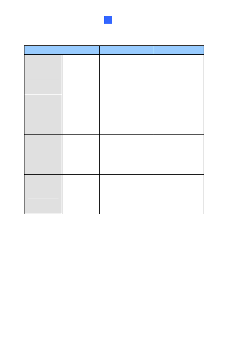
Device Description
Power Adapter
The power adapter is available for all Vandal Proof
IP Dome. Contact our sales representatives for the
countries and areas supported.
GV-PA191 PoE
Adapter
The GV-PA191 PoE adapter is designed to provide
power and network connection to the cameras over
a single Ethernet cable.
GV-POE Switch
The GV-POE Switch is designed to provide power
along with network connection for IP devices. The
GV-POE Switch is available in various models with
different numbers and types of ports.
GV-Mount
Accessories
The GV-Mount Accessories provide a
comprehensive lineup of accessories for installation
on ceiling, wall corner and pole. For details, see GV-
Mount Accessories Installation Guide.
GV-Relay V2
The GV-Relay V2 is designed to expand the voltage
load of GV IP devices. It provides 4 relay outputs,
and each can be set as normally open (NO) or
normally closed (NC) independently as per your
requirement.
Note: GV-Relay V2 does not support GV-EVD2100 /
3100 / 5100.
vii
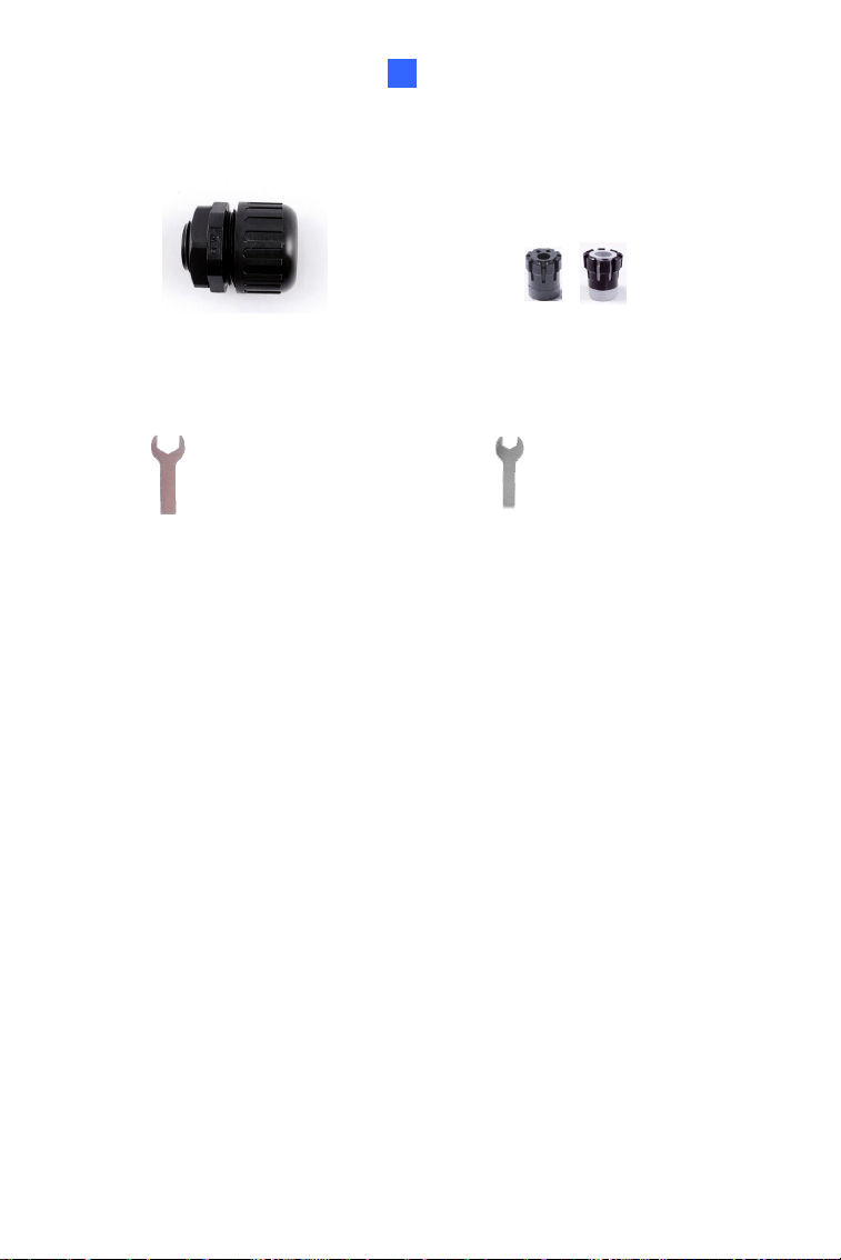
Device Description
Metal PG21
Conduit
Connector
The metal PG21 conduit connector is used for
running the wires of GV-VD1530 / 2430 / 2530 /
3430, GV-VD1540 / 2440 / 2540 / 3440 / 4711 /
5340 / 5711, GV-VD2540-E / 5340-E, GV-VD2702 /
2712 / 4702 / 4712, and GV-EVD2100 / 3100 / 5100
through a 3/4” conduit pipe.
Weatherproof
Shield
The weatherproof shield is made for GV-VD1530 /
2430 / 2530 / 3430, GV-VD1540 / 2440 / 2540 /
3440 / 4711 / 5340 / 5711, and GV-VD2540-E /
5340-E to protect the camera from rain and snow.
Creating GV-IP Camera’s Login
Credentials
The default Administrator and Guest accounts are no longer supported by
GV-IPCam H.265 series firmware V1.14 or later. When purchasing a new
camera or performing factory resetting, you need to set up a login
username and password for the camera.
1. Download and install GV-IP Device Utility from the company
website.
2. On the GV-IP Device Utility window, click
to search for your GV-
IP camera.
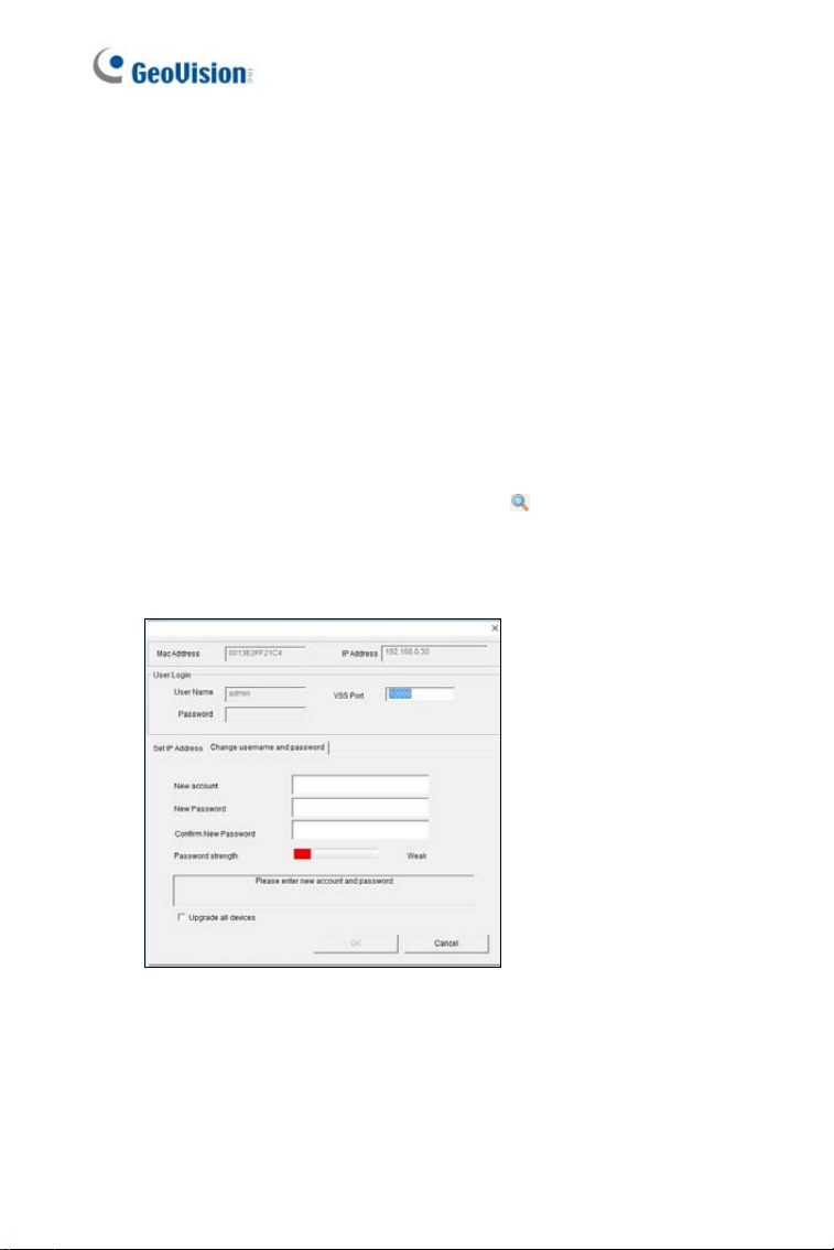
3. Double-click your GV-IP camera in the GV-IP Device Utility list. This
dialog box appears.
4. Click the Change Username and Password tab to type a new
username and password. Note that the new password must meet
the password strength requirements.
5. Optionally click Upgrade all devices to use the same username
and password on all other devices.
viii
ix
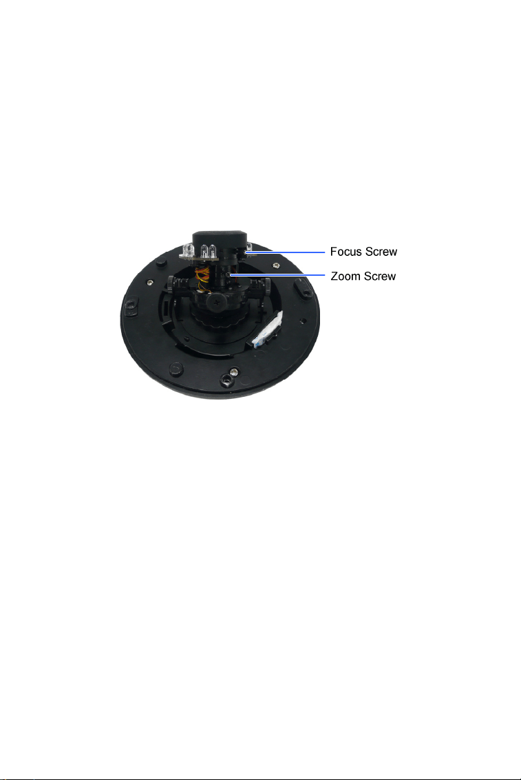
Note for Adjusting Focus and Zoom
When adjusting the Focus and Zoom Screws, do not over tighten the
Focus and Zoom screws. The screws only need to be as tight as your
finger can do it. It is not necessary to use any tools to get them tighter.
Doing so can damage the structure of lens.
The maximum torque value for all the zoom and focus screws is 0.049 N.m
x
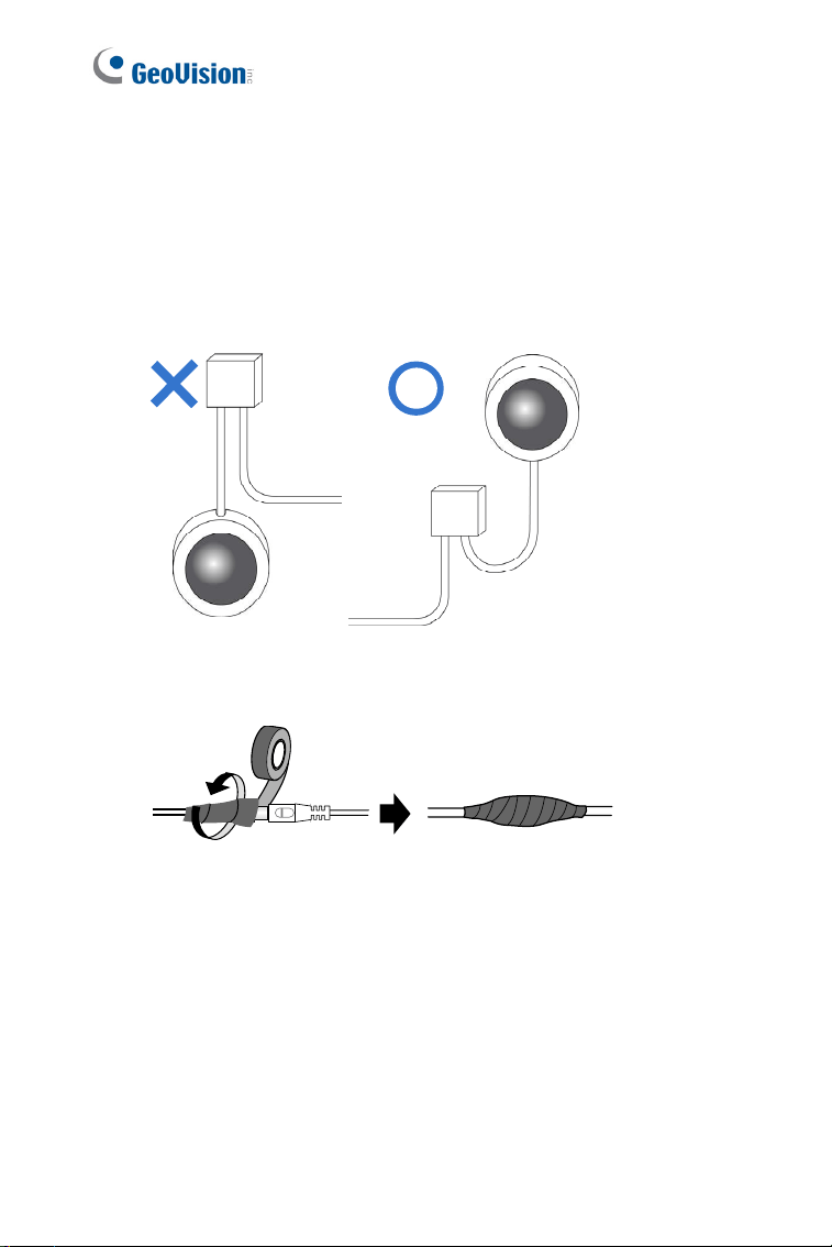
Note for Installing Camera Outdoor
When installing the camera outdoor, be sure that:
1. The camera is set up above the junction box to prevent water from
entering the camera along the cables.
2. Any PoE, power, audio and I/O cables are waterproofed using
waterproof silicon rubber or the like.
xi
3. After opening the camera cover, ensure the screws are tightened
and the cover is in place.
4. Make sure the housing cover is properly secured to prevent water
from entering and damaging the inner housing.

xii
Note for Silica Gel Bags
1. The silica gel bag loses it effectiveness when the dry camera is
opened. To prevent the lens from fogging up, replace the silica gel
bag every time you open the camera, and conceal the gel bag in
camera within 2 minutes of exposing to open air.
2. When the camera is shipped, a silica gel bag will be included inside
the camera. For the first-time user, replace the silica gel bag prior to
the installation to avoid foggy live view.
Note for TV-out Function
Some cameras have a TV-out connector. The TV-out function can only be
used during installation to adjust the focus of the camera. To use the TV
out function, connect the supplied black BNC wire to a monitor and select
your signal format (NTSC or PAL) at the TV Out field on the Web interface.
The default signal format is NTSC. For details, see 4.1.1 Video Settings,
GV-IPCam Firmware Manual. The TV-out wire must be removed before
you secure the housing cover.
1
Chapter 1 Vandal Proof IP Dome
(Part I)
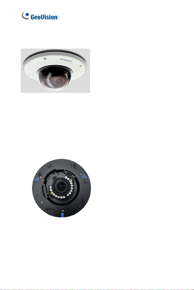
The Vandal Proof IP Dome is a series of outdoor camera designed for
vandal protection. They are equipped with automatic infrared cut filters and
IR LED for day and night surveillance. The WDR Pro models can produce
clear image for scenes containing contrasting intensity of lights. The super
low lux models can display color live view in near darkness.
These Vandal Proof IP Domes can be installed on wall and ceiling using
the standard package. They can also be installed on wall corners and
poles using the GV-Mount accessories (optional). For more details, see
GV-Mount Accessories Installation Guide.
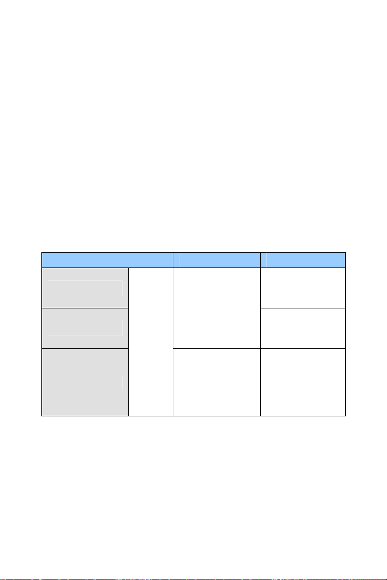
Model No. Specification Description
GV-VD120D
(IK10+, Transparent Cover)
GV-VD121D
(IK10+, Smoked Cover)
GV-VD122D
(IK7, Transparent Cover)
GV-VD123D
(IK7, Smoked Cover)
Varifocal
Lens
Auto Iris, f:3 ~ 9
mm, F/1.3, 1/2.7”
ø 14 mm lens
mount
1.3 MP Low
Lux, H.264
2
Model No. Specification Description
GV-VD220D
(IK10+, Transparent Cover)
GV-VD221D
(IK10+, Smoked Cover)
GV-VD222D
(IK7, Transparent Cover)
GV-VD223D
(IK7, Smoked Cover)
2 MP, H.264
GV-VD320D
(IK10+, Transparent Cover)
GV-VD321D
(IK10+, Smoked Cover)
GV-VD322D
(IK7, Transparent Cover)
GV-VD323D
(IK7, Smoked Cover)
Varifocal
Lens
Auto Iris, f:3 ~ 9
mm, F/1.3, 1/2.7”
ø 14 mm lens
mount
3 MP, H.264
GV-VD1500
(IK10+, Transparent Cover)
GV-VD2500
(IK10+, Transparent Cover)
1.3 MP / 2 MP
Super Low Lux
GV-VD2400
(IK10+, Transparent Cover)
GV-VD3400
(IK10+, Transparent Cover)
Varifocal
Lens
Auto Iris, f:3 ~ 9
mm, F/1.2, 1/2.7”
ø 14 mm lens
mount
2 MP / 3 MP,
H.264, WDR
Pro
Vandal Proof IP Dome (Part I)
3
1
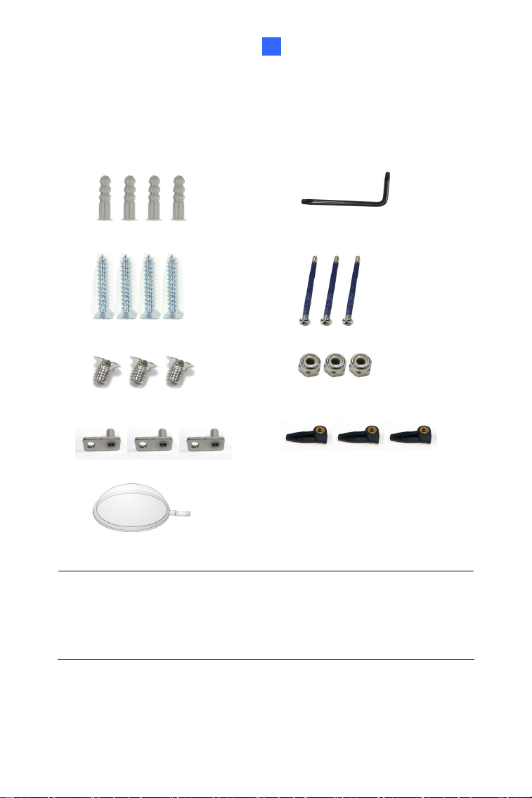
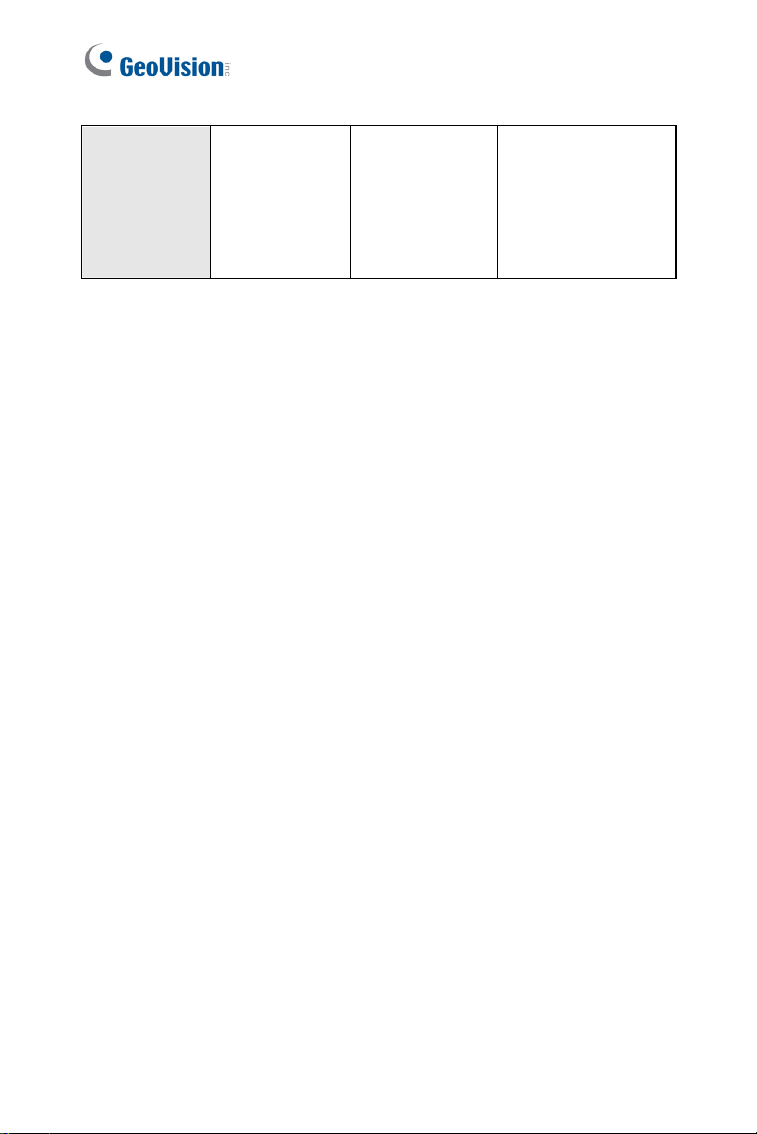
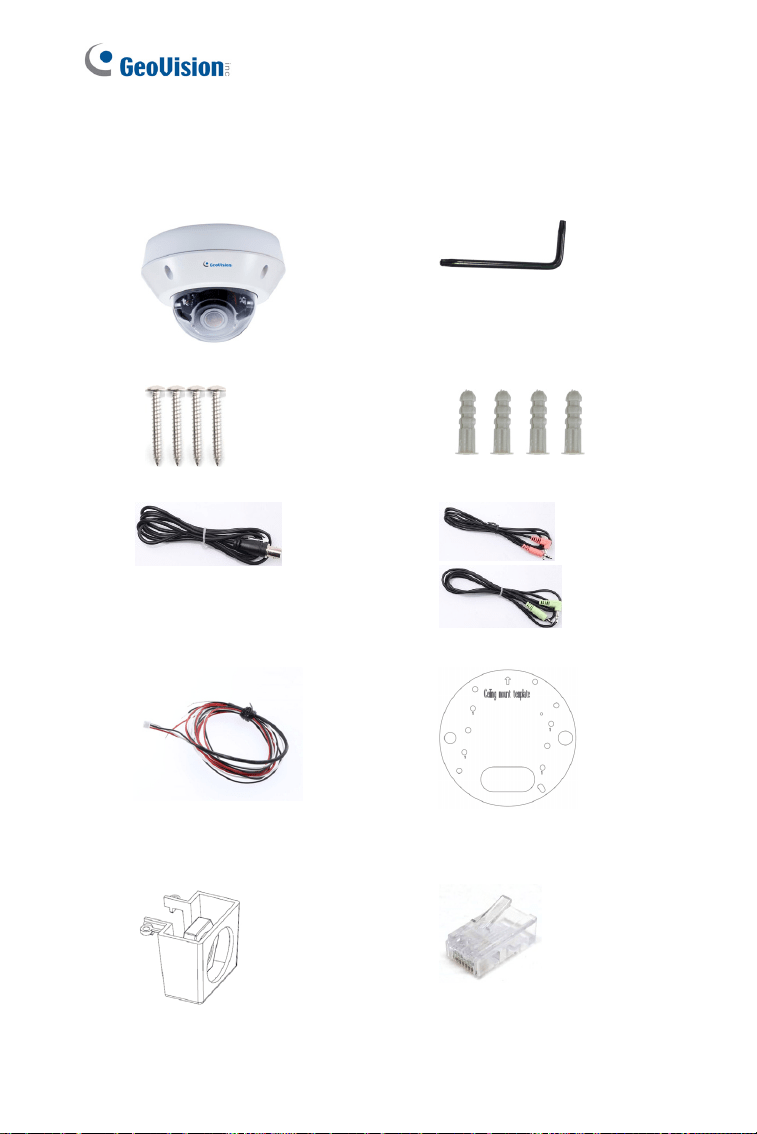
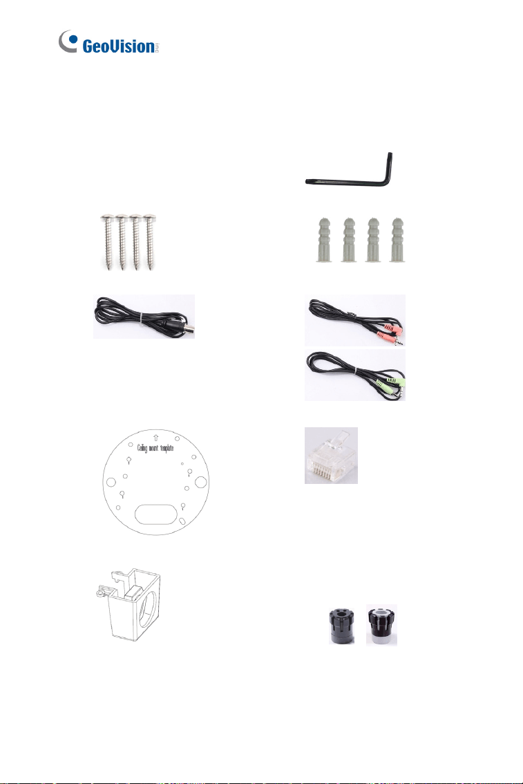
1.1 Packing List
Vandal Proof IP Dome Silica Gel Bag x 2
Screw Anchor x 4
Torx Wrench
Ceiling Screw x 4
Blue Screw x 3
T-Cap Screw x 3
Small Screw Cap x 3
T-Cap x 3
Plastic Clip x 3
Focus Adjustment Cap
2-Pin Terminal Block
Power Adapter
Download Guide Warranty Card
Note:
1. Focus Adjustment Cap is only needed and supplied for IK10+
models.
2. The power adapter can be excluded upon request.
4
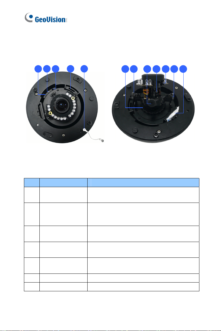
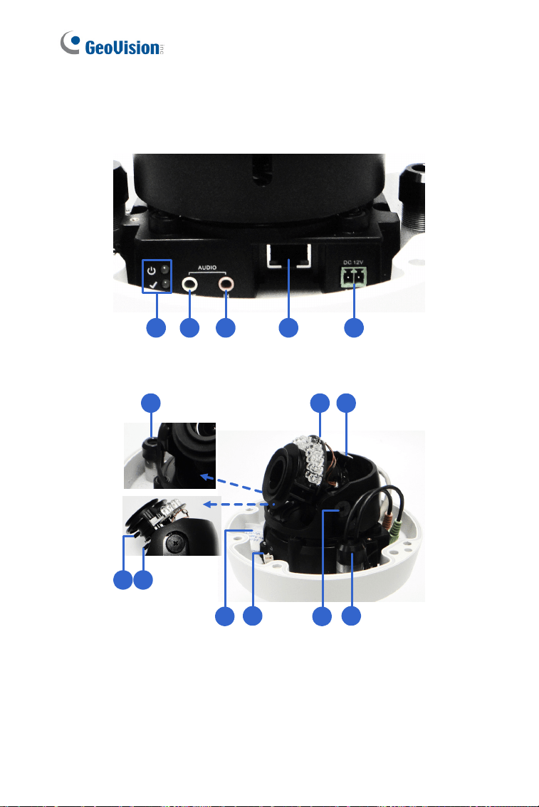
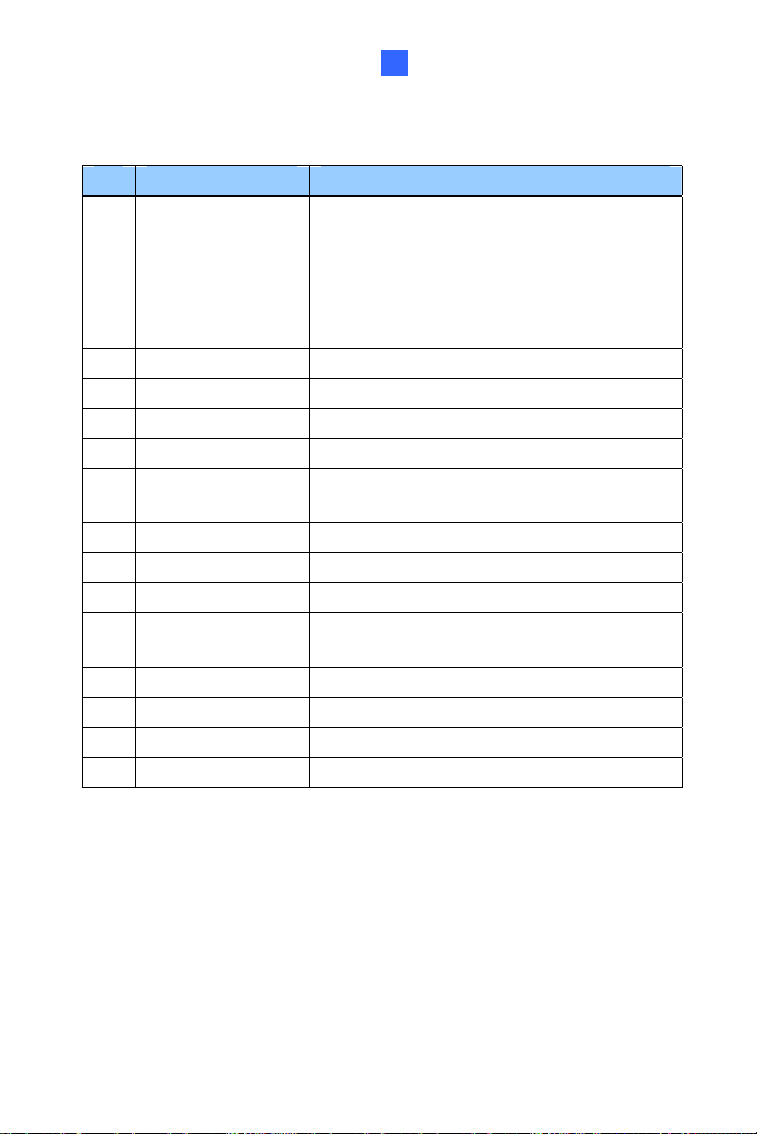
1.2 Overview
1
2
3
4 5
6 7 8 9 7
10 11
Figure 1-1
No. Name Description
1 Power LED
Turns on (green) when the power is on and
turns off when there is no power supply.
2 Status LED
Turns on (green) when the system operates
normally and turns off when system error
occurs.
3 Default Button
Resets the camera to factory default. For
details, see 1.5 Loading Factory Default.
4
Memory Card
Slot
Inserts a micro SD card (SD/SDHC, version
2.0 only, Class 10) to store recording data.
5
Thread Lock Locks the housing cover to the camera body
to prevent the cover from falling.
6 Pan Disc Loosens to pan the camera.
7 Tilt Screw Loosen the screw to tilt the camera.

Vandal Proof IP Dome (Part I)
5
1
No. Name Description
8 Rotational Screw Loosens to adjust the camera angle.
9 Zoom Screw Adjusts the zoom of the camera.
10 Focus Screw Adjusts the focus of the camera.
11 Silica Gel Bag Absorbs moisture in the camera body.
6
1.3 Installation
The Vandal Proof IP Dome is designed for outdoors. With the standard
package, there are two ways to install the Vandal Proof IP Dome:
hard-
ceiling mount
and in-ceiling mount.
Note: You can also install the camera:
on a power box (of the 4" square and double gang type) using the
standard package
to ceilings, wall corners (concave or convex), and poles using
optional mounting kits
For details on these installations, see GV-Mount Accessories Installation
Guide.
Vandal Proof IP Dome (Part I)
7
1
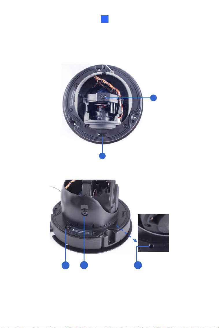
1.3.1 Hard-Ceiling Mount
Figure 1-2
1. Unpack the camera package and take out the camera body.
Unscrew the
housing cover
Unscrew thread
lock
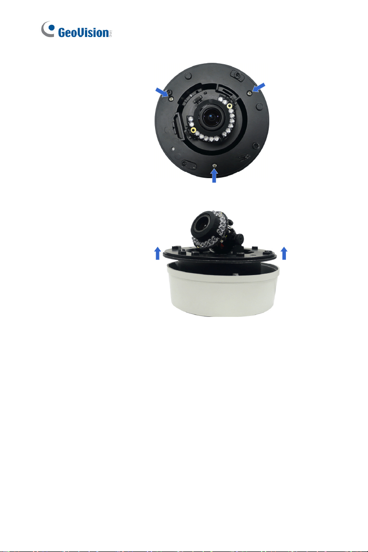
8
Unscrew the inner
housing
Take out the
camera body
Vandal Proof IP Dome (Part I)
9
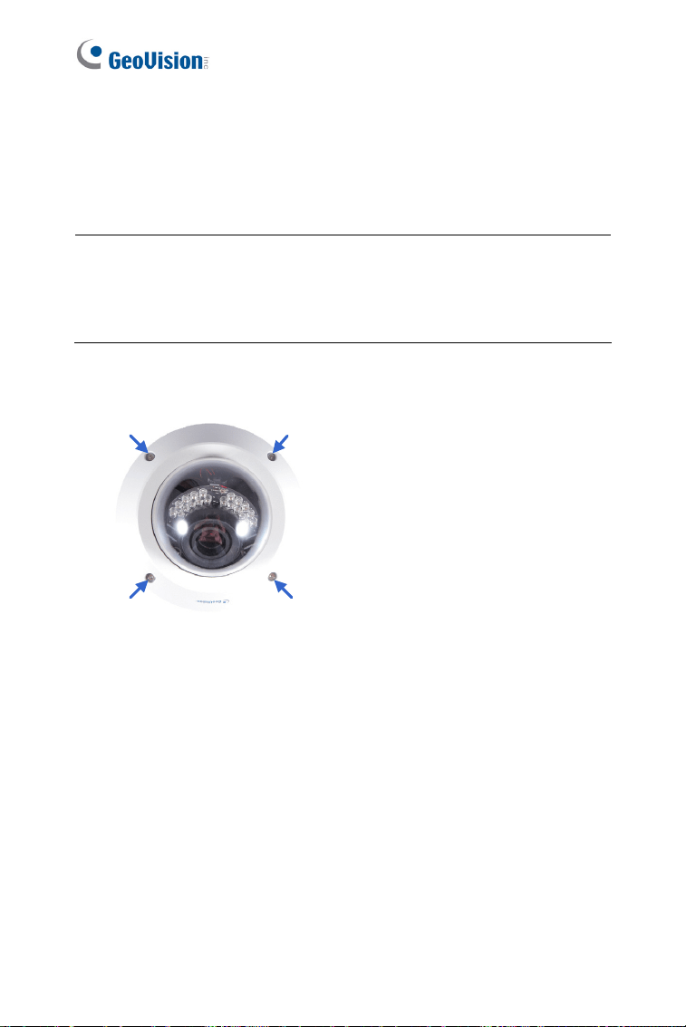
1
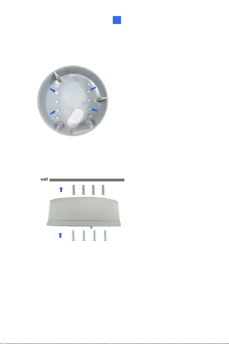
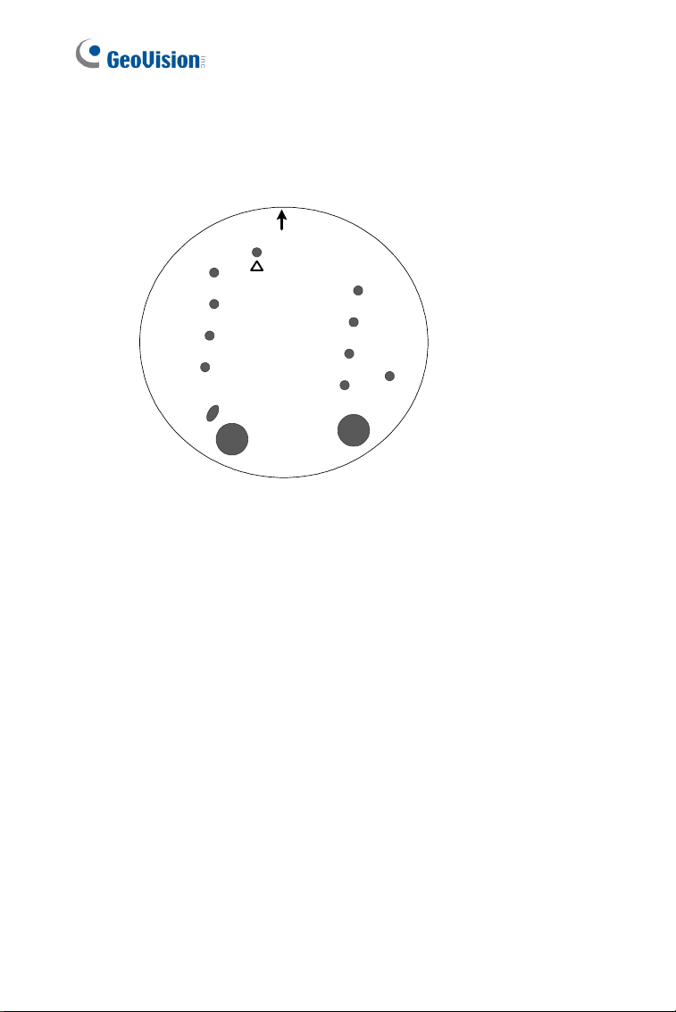
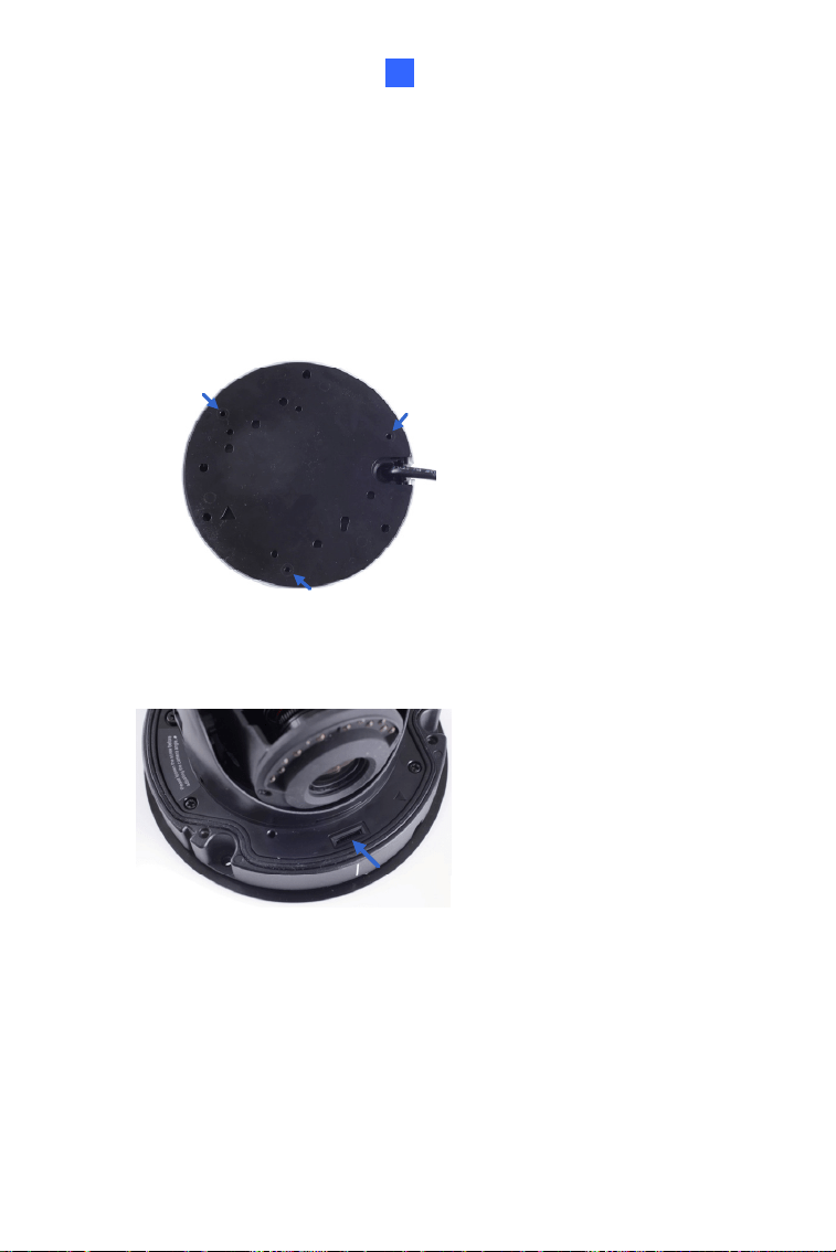
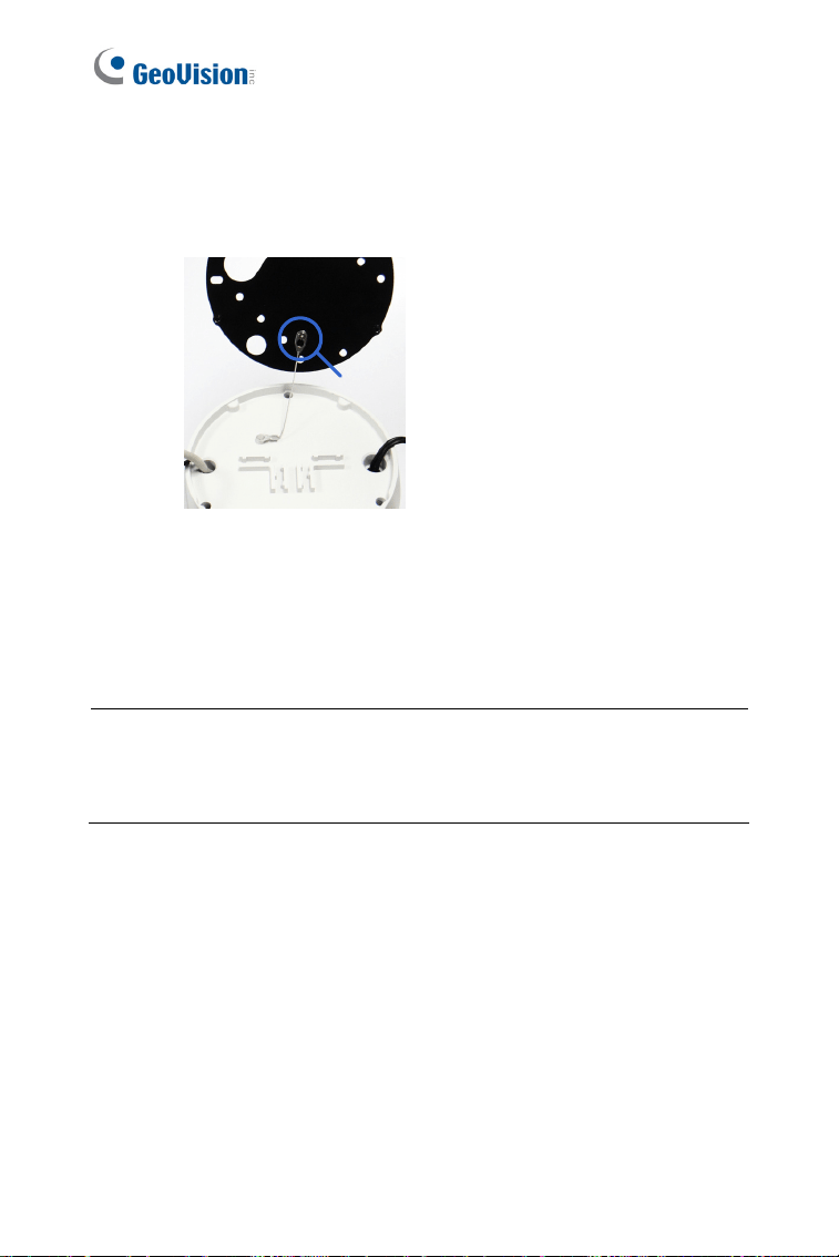
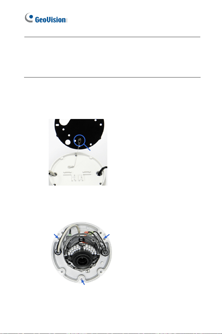
2. Mark the position of four screw holes on the desired installation
location, and drill holes in the marked locations. Drill the ellipse part if
you wish to put the wires through it.
Figure 1-3
3. Insert the screw anchors to the 4 holes on the ceiling.
4. Secure the back cover to the ceiling with 4 ceiling screws.
Figure 1-4
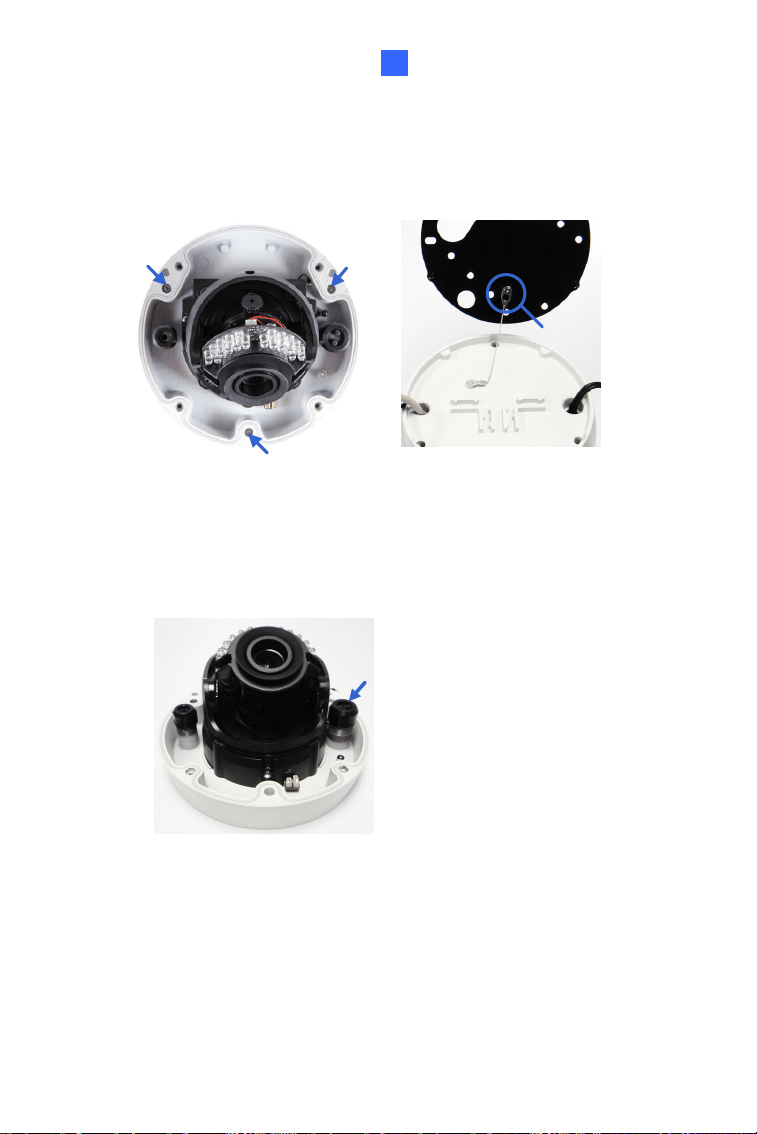
5. Refer to step 1 to secure the camera body with inner housing.
6. Thread the cable through the conduit entry at the side of the back
cover. Alternatively pass the wires through the ellipse hole at the
bottom of the back cover.
10
7. Connect the network, power and other cables to the camera. See 1.4
Connecting the Camera.
8. Access the live view. See 6.2 Accessing the Live View.
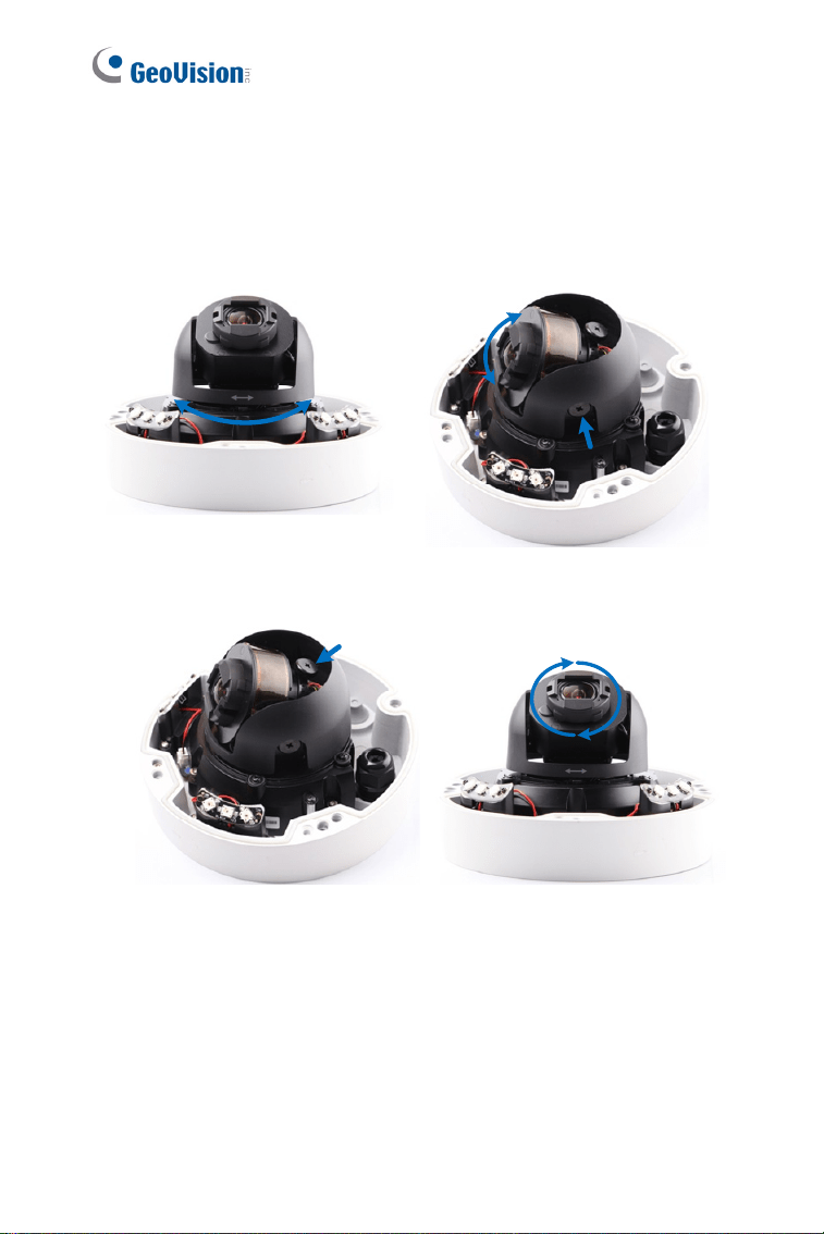
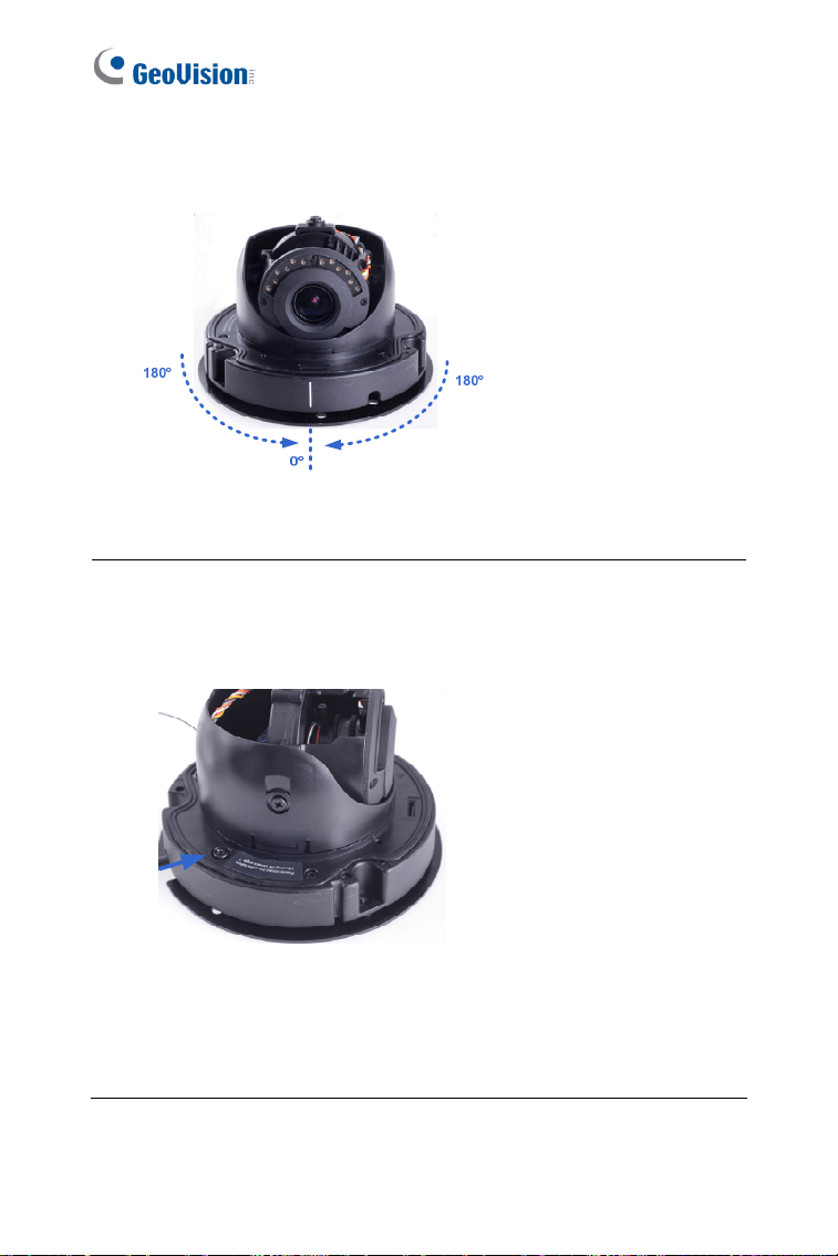
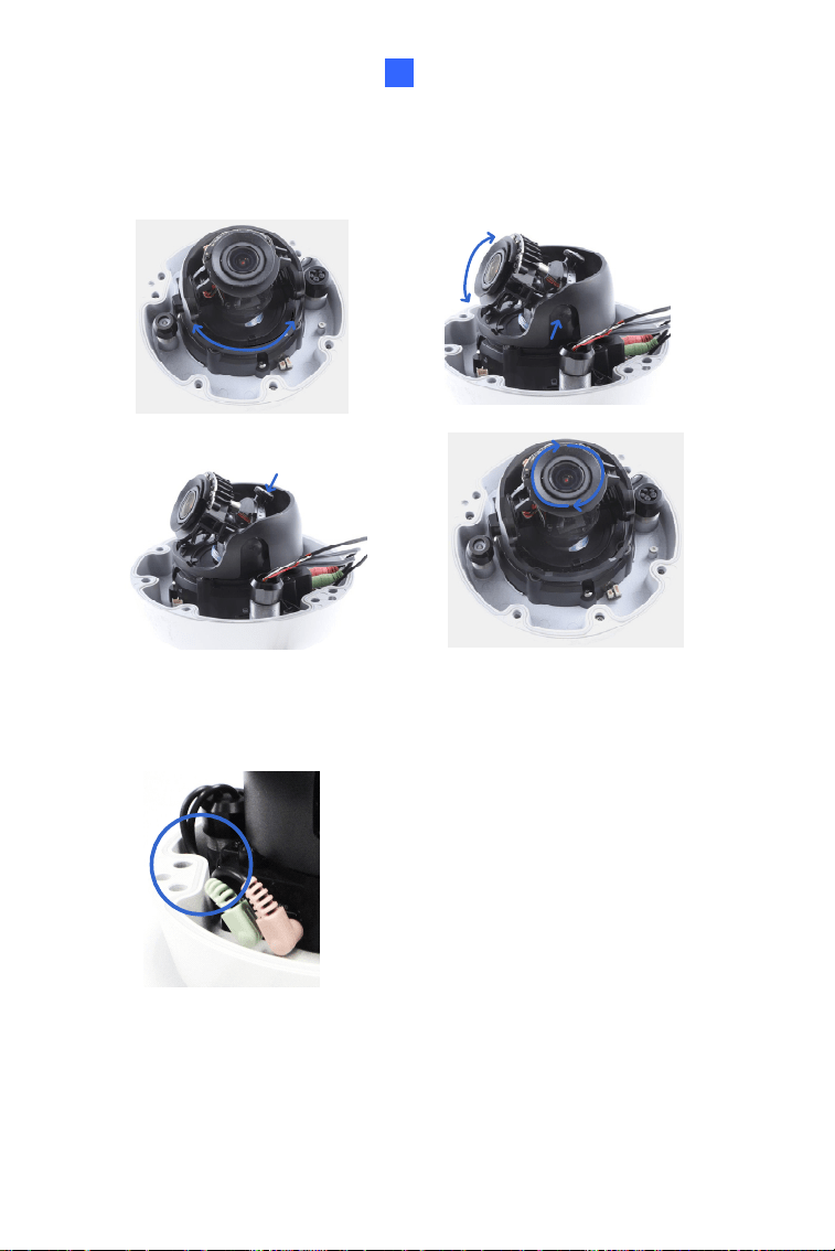
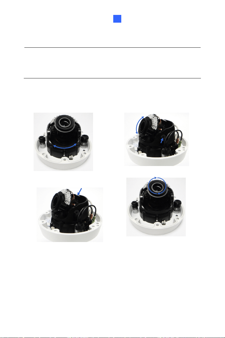
9. Based on the live view, adjust the camera to a desired angle as
illustrated below.
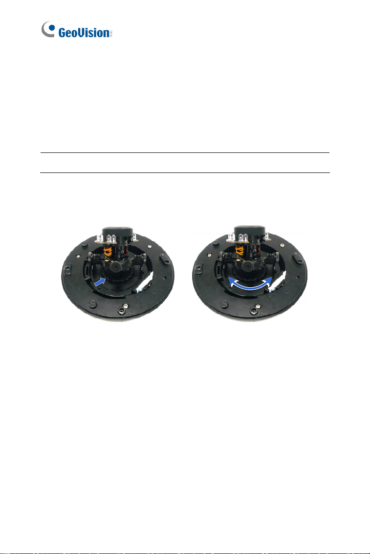
Tip: The 3-axis mechanism offers flexible and easy installation.
Pan Adjustment
Figure 1-5
Vandal Proof IP Dome (Part I)
11
1
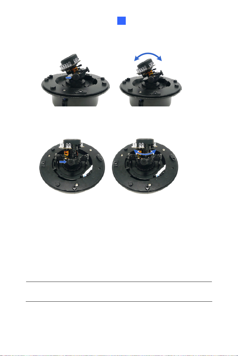
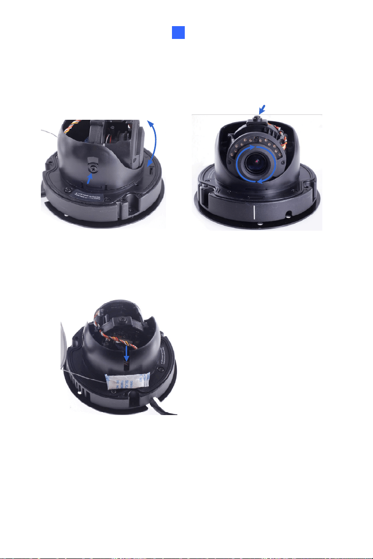
Tilt Adjustment
Rotational Adjustment
Figure 1-6
10. Adjust image clarity using the GV-IP Device Utility program. For
details, see 6.3 Adjusting Image Clarity.
11. Screw on the thread lock as shown in step 1.
12. Replace the silica gel bag on the camera body within 2 minutes of
opening the silica gel bag package.
13. Secure the housing cover to the camera body as shown in step 1.
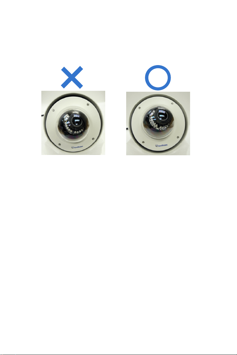
Note: Adjust the black mask inside the housing cover to make sure the
camera view is not obscured.
12
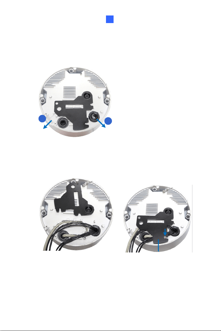
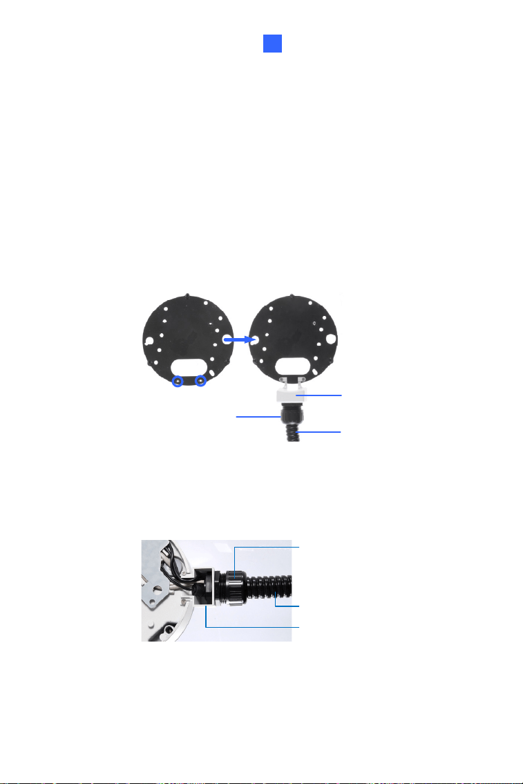
1.3.2 In-Ceiling Mount
Figure 1-7
1. Follow step 1 in 1.3.1 Hard-Ceiling Mount section to remove the
housing cover, thread lock and back cover, and take out the camera
body.
2. Cut out a circle with a diameter of 142 mm on the ceiling.
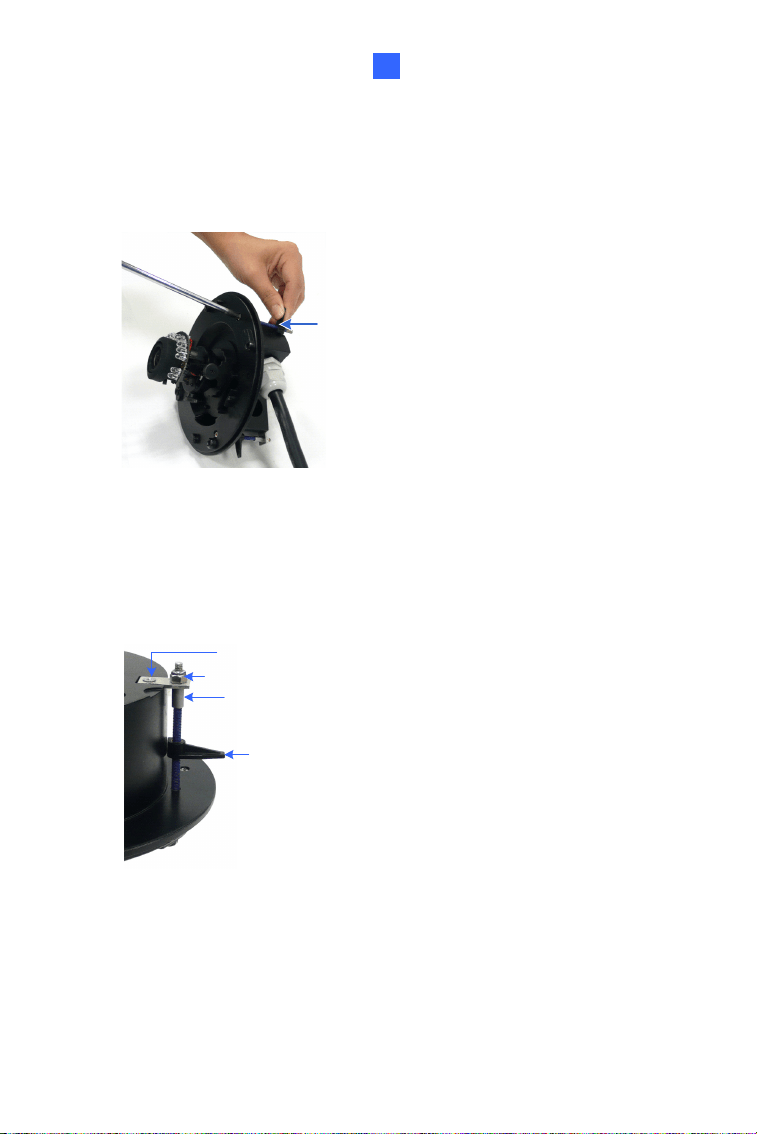
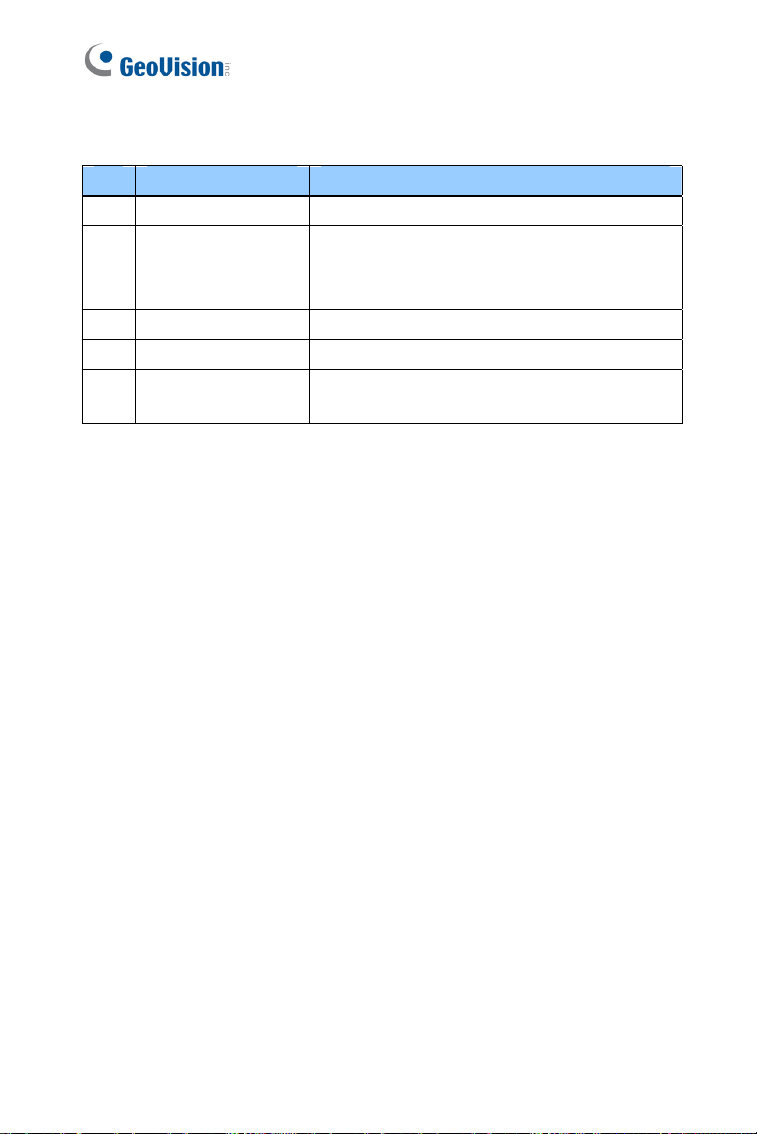
3. Insert a blue screw to the indicated holes on the camera body.
Figure 1-8
Vandal Proof IP Dome (Part I)
13
1
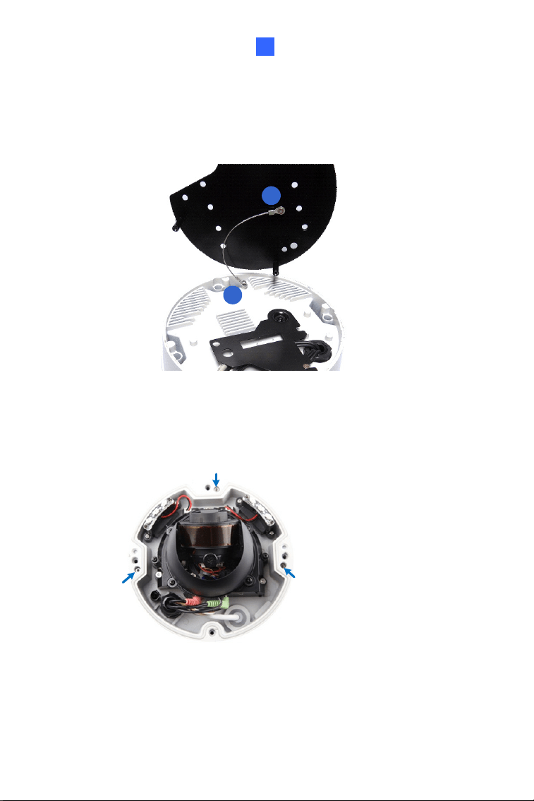
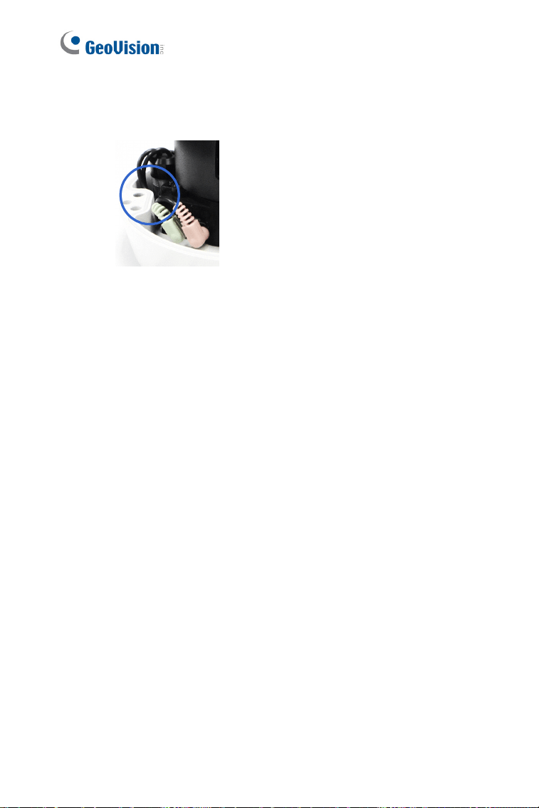
4. Screw in a plastic clip to the blue screw, hold it with one hand and use
a screw driver to rotate the blue screw until the plastic clip moves half
way down.
Plastic Clip
Figure 1-9
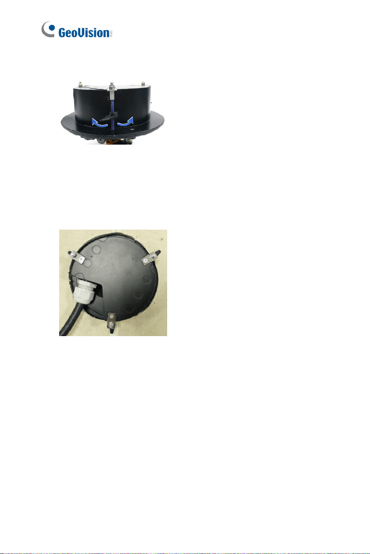
5. Secure a T-cap on top of the blue screw with a small screw cap and a
T-cap screw. Do not tighten the small screw cap so that the plastic
clip can move down freely.
small screw cap
T-cap
plastic clip
T-cap screw
Figure 1-10
6. Repeat steps 4 and 5 for the other two blue screws.
14
7. Insert the camera to the ceiling with the plastic screws moved inward.
Figure 1-11
8. Move the blue screws out and rotate the blue screw with a screw
driver until the plastic clip and the bottom of the camera body clamps
the ceiling tightly.
Figure 1-12
9. Connect the network, power and other cables to the camera. See 1.4
Connecting the Camera.
10. Access the live view. See 6.2 Accessing the Live View.
11. Follow steps 9 to 10 in 1.3.1 Hard-Ceiling Mount section to adjust the
angle, focus and zoom of the camera.
12. Follow steps 11 to 13 in 1.3.1 Hard-Ceiling Mount section to secure
the thread lock, replace the silica gel bag and secure the housing
cover.
Vandal Proof IP Dome (Part I)
15
1
1.4 Connecting the Camera
Connect your Vandal Proof IP Dome to power, network and other cables
needed.
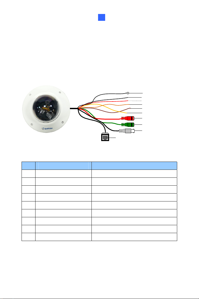
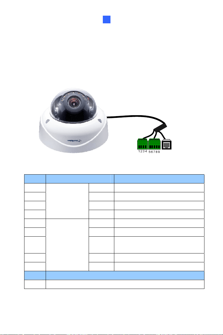
1.4.1 Wire Definition
The cables of Vandal Proof IP Dome are illustrated and defined below.
Ethernet (PoE)
TV out
Audio out (green)
Audio in (red)
Digital in (oragne)
Ground (yellow)
Digital out (brown)
Shielding ground
DC 12V+ / AC 24V+
DC 12V- / AC 24V-
Figure 1-13
No. Wire Color Definition
1 Black (thick) Shielding Ground
2 Black (thin) DC 12V- / AC 24V-
3 Red DC 12V+ / AC 24V+
4 Orange Digital In
5 Brown Digital out
6 Yellow Ground
7 Red RCA Audio in
8 Green RCA Audio out
9 Black BNC TV out
16
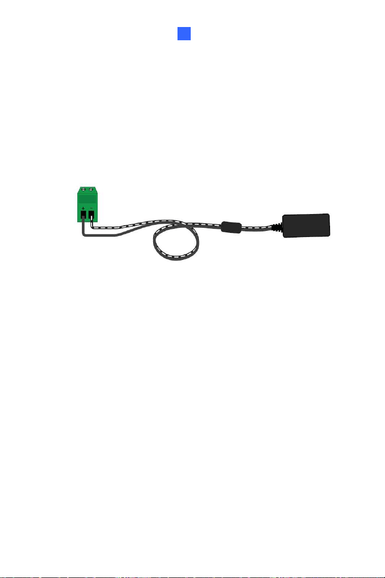
1.4.2 Power Connection
There are two ways to supply power to the camera:
Use a Power over Ethernet (PoE) adapter to connect the camera to the
network, and the power will be provided at the same time.
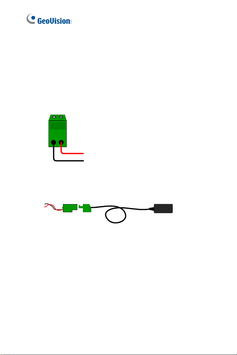
Plug the power adapter to the 12V terminal block as shown below.
1. Insert the thin black wire of the Vandal Proof IP Dome to the left
pin (-) and the red wire to the right pin (+).
Figure 1-14
2. Connect the DC 12V Power Adapter to the Terminal Block.
DC 12V Power Adaptor
Terminal Block
Figure 1-15
Vandal Proof IP Dome (Part I)
17
1
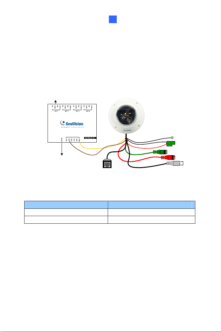
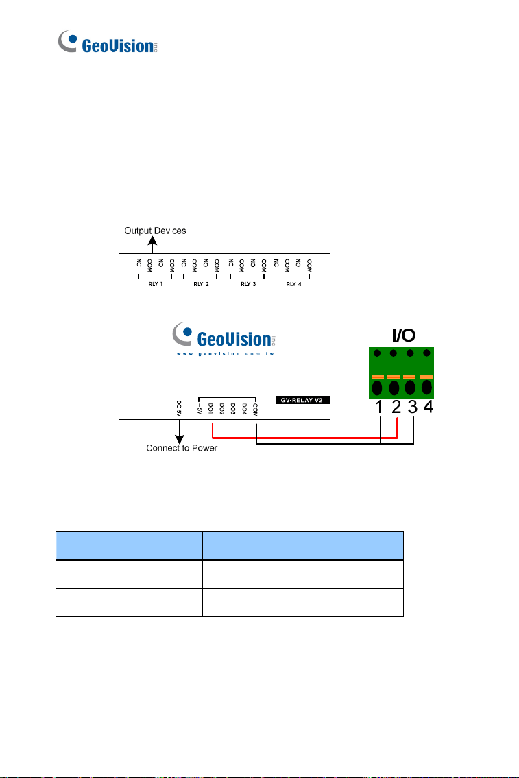
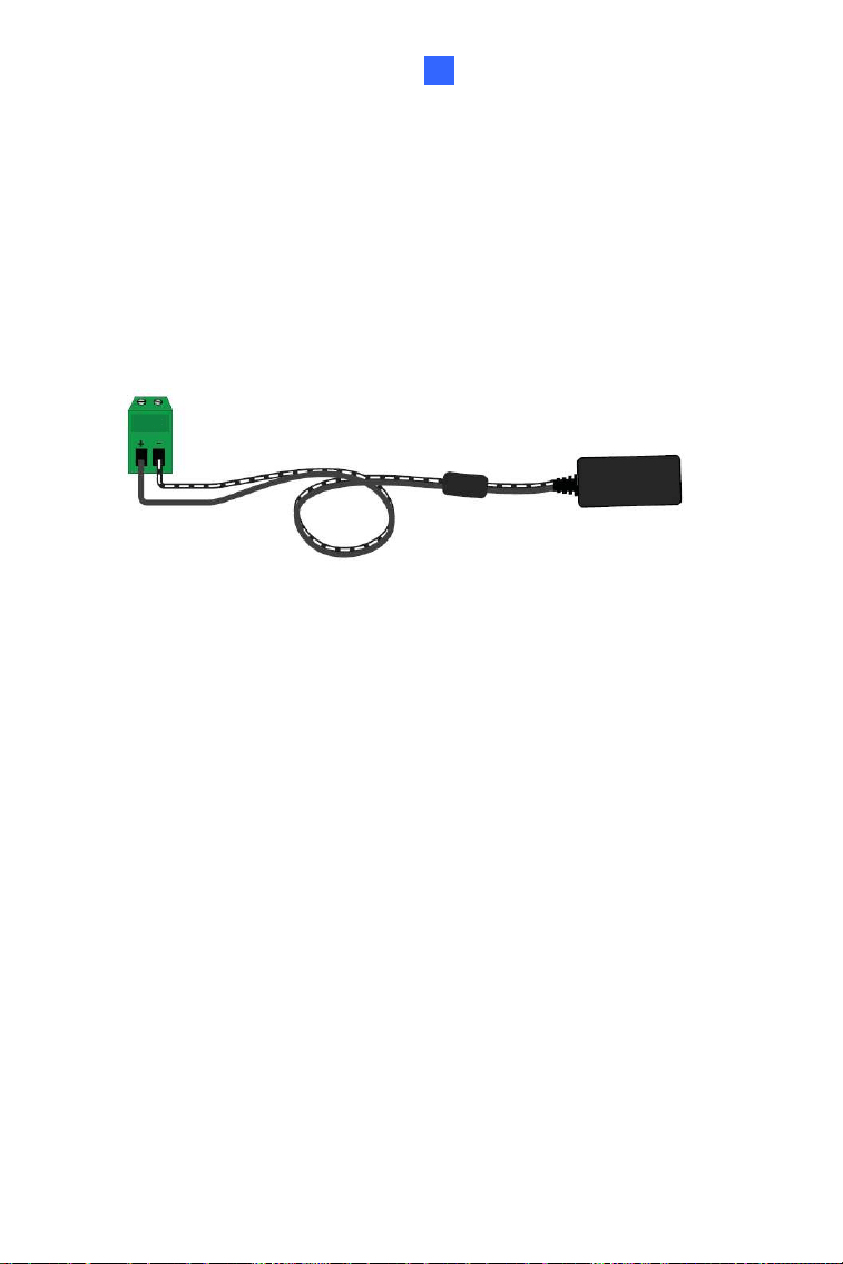
1.4.3 Voltage Load Expansion (Optional)
The camera can only drive a maximum load of 200mA 5V DC. To expand
the maximum voltage load to
10A 250V AC, 10A 125V AC or 5A 100V DC,
connect the camera to a GV-Relay V2 module (optional product). Refer to
the figure and table below.
Output Devices
Connect to Power
Figure 1-16
GV-Relay V2 Vandal Proof IP Dome
COM Ground (Yellow)
DO1 Digital Out (Brown)
18
1.5 Loading Factory Default
You can restore factory default settings through the Web interface or
directly on the camera.
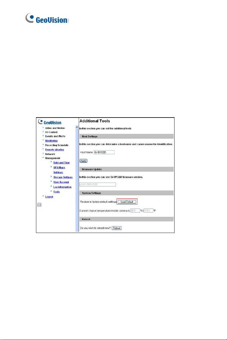
1.5.1 Using the Web Interface
1. On the left menu of Web interface, select Management and select
Tools. The Additional Tools dialog box appears.
2. Click the
Load Default button in the System Settings section.
Figure 1-17
Vandal Proof IP Dome (Part I)
19
1
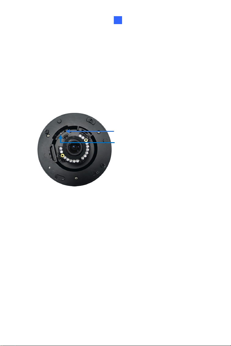
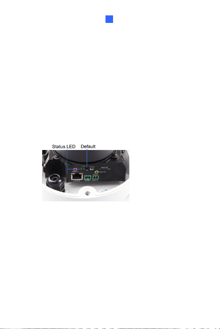
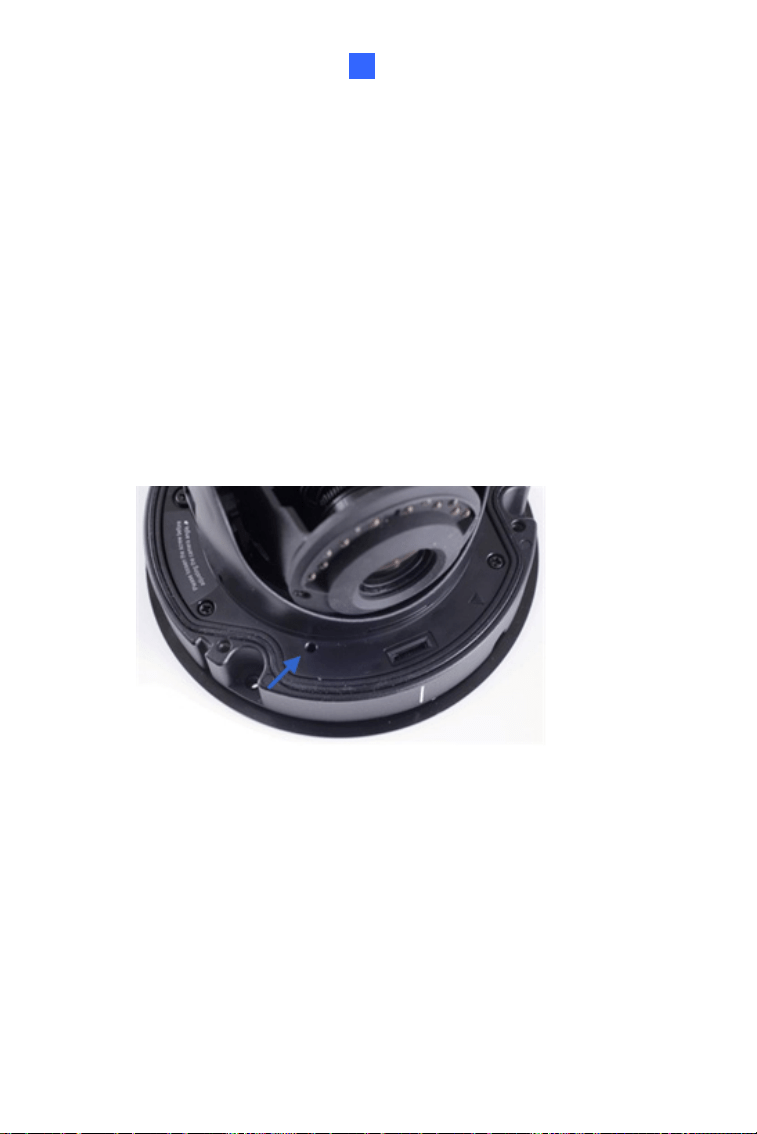
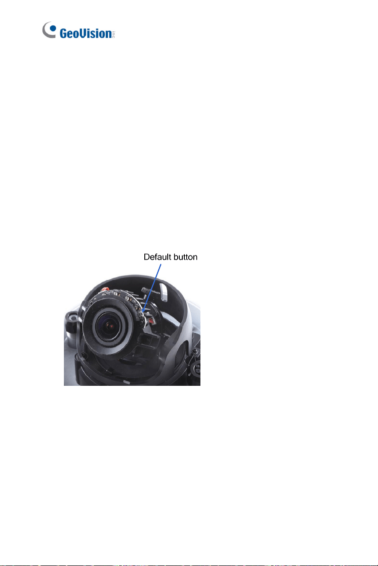
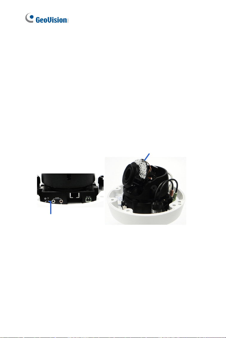
1.5.2 Directly on the Camera
1. Keep the power and network cables (or PoE) connected to the camera.
2. Use a pin to press and hold the
default button on the inner housing.
3. Release the
default button when the status LED blinks. This shall
take about 8 seconds.
4. When the
status LED fades, the process of loading default settings is
completed and the camera reboots automatically.
Status LED
Default button
Figure 1-18
5. Insert a new Silica Gel Bag and fasten the camera’s cover
immediately.

20
Chapter 2 Vandal Proof IP Dome
(Part II)
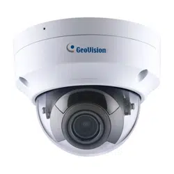
These Vandal Proof IP Domes are outdoor cameras designed with IK10+
vandal resistance and IP67 ingress protection. They provide superior night
vision with their high power LEDs and allow up to 20 m (65.6 ft), 25 m (82
ft), 30 m (98.4 ft) effective IR distance. The
super low lux models are able
to display color live view in dear darkness. The
WDR Pro models can
process scenes with contrasting intensity of lights. The
motorized
varifocal models support remote focus and zoom adjustment. The arctic
models can withstand extreme temperatures.
These Vandal Proof IP Domes can be installed on the ceiling using the
standard package. They can also be installed on wall surfaces, wall
corners and poles using the GV-Mount accessories (optional). For more
details, see GV-Mount Accessories Installation Guide.
Vandal Proof IP Dome (Part II)
21
2
Model No. Specification Description
GV-VD1530
GV-VD2430
GV-VD2530
GV-VD3430
Varifocal
lens
1.3 MP Super Low
Lux / 2 MP WDR
Pro / 2 MP Super
Low Lux / 3 MP
WDR Pro, H.264,
GV-VD1540
GV-VD2440
GV-VD2540
GV-VD3440
Motorized
varifocal lens,
high power IR
LEDs
1.3 MP Super Low
Lux / 2 MP WDR
Pro / 2 MP Super
Low Lux / 3 MP
WDR Pro, H.264,
GV-VD2540-E
Motorized
varifocal lens,
high power IR
LEDs, extreme
temperature
tolerance
Auto Iris,
f:3 ~ 9 mm,
F/1.2, 1/2.7”
ø 14 mm lens
mount
2 MP Super Low
Lux, H.264
GV-VD4711
Motorized
varifocal lens,
high power IR
LEDs
Auto Iris,
f: 2.8 ~ 12 mm,
F/1.7, 1/2.7”
ø 14 mm lens
mount
4 MP Super Low
Lux, WDR Pro,
H.265
GV-VD5711
Motorized
varifocal lens,
high power IR
LEDs
Auto Iris,
f: 4 ~ 8 mm,
F/1.65, 1/1.8”
ø 14 mm lens
mount
5 MP. Low Lux,
WDR, H.265
GV-VD5340
Motorized
Varifocal Lens,
high power IR
LEDs
Auto Iris,
f: 3.3 ~ 9 mm,
F/1.2, 1/2.7”
5 MP, H.264
22
GV-VD5340-E
Motorized
varifocal Lens,
high power IR
LEDs, extreme
temperature
tolerance
ø 14 mm lens
mount
Vandal Proof IP Dome (Part II)
23
2
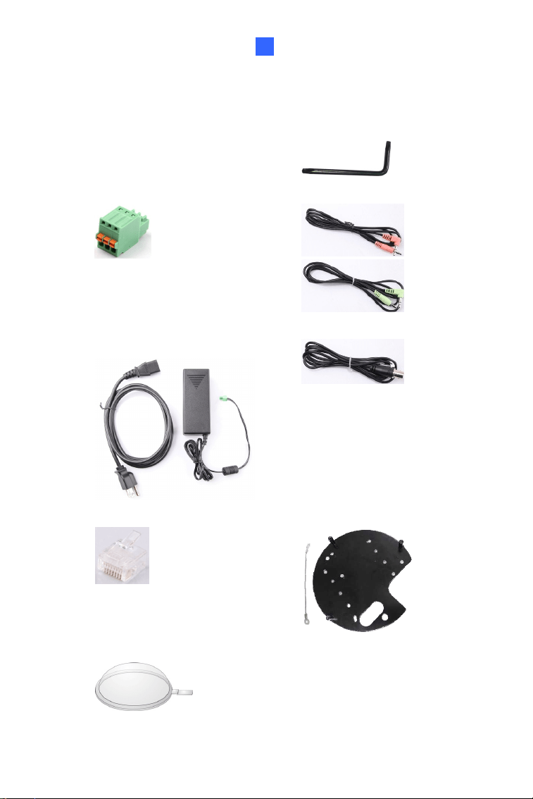
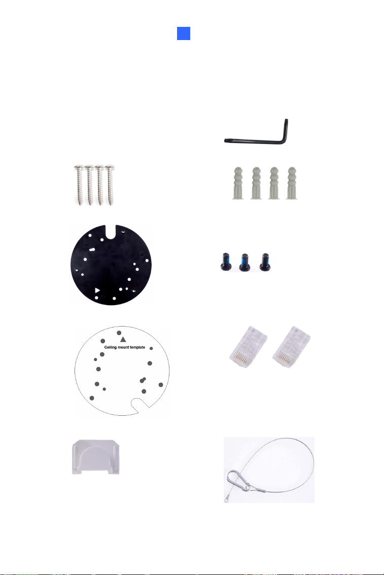
2.1 Packing List
Vandal Proof IP Dome Torx Wrench
3-Pin Terminal Block
Audio wires x 2
Power Adapter (excluding
GV-VD4711 / 5711)
TV out wire
RJ-45 Connector x 2
Back Plate
Focus Adjustment Cap (for GV-VD1530 / 2430 / 2530 / 3430 only)
24
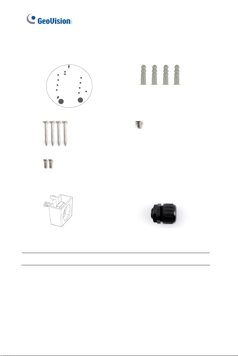
Installation sticker
1
1
1
Ceiling mount template
Screw Anchor x 4
Long Screw x 4
Flat Screw
Short Screw x 2
Silica Gel Bag
Sticker (for Silica Gel Bag) Ruler
Conduit Converter
Plastic PG21 conduit
connector
Download Guide Warranty Card
Note: The power adapter can be excluded upon request.
Vandal Proof IP Dome (Part II)
25
2
Note: You can choose to run the wires through a conduit pipe. After you
have threaded all the wires, install the supplied conduit converter and
plastic PG21 conduit connector with a self-prepared 1/2’’ conduit pipe
to the camera. Power will have to be supplied through a PoE adapter,
because the power adapter wire does not fit in a 1/2” pipe. You will have
to purchase your own PG21 conduit connector if you want to use 3/4” or
1” pipe.
Conduit pipe
Conduit converter
Plastic PG21
conduit connector
A metal PG21 conduit connector can be purchased upon request,
which can be connected with a 3/4” pipe.
26
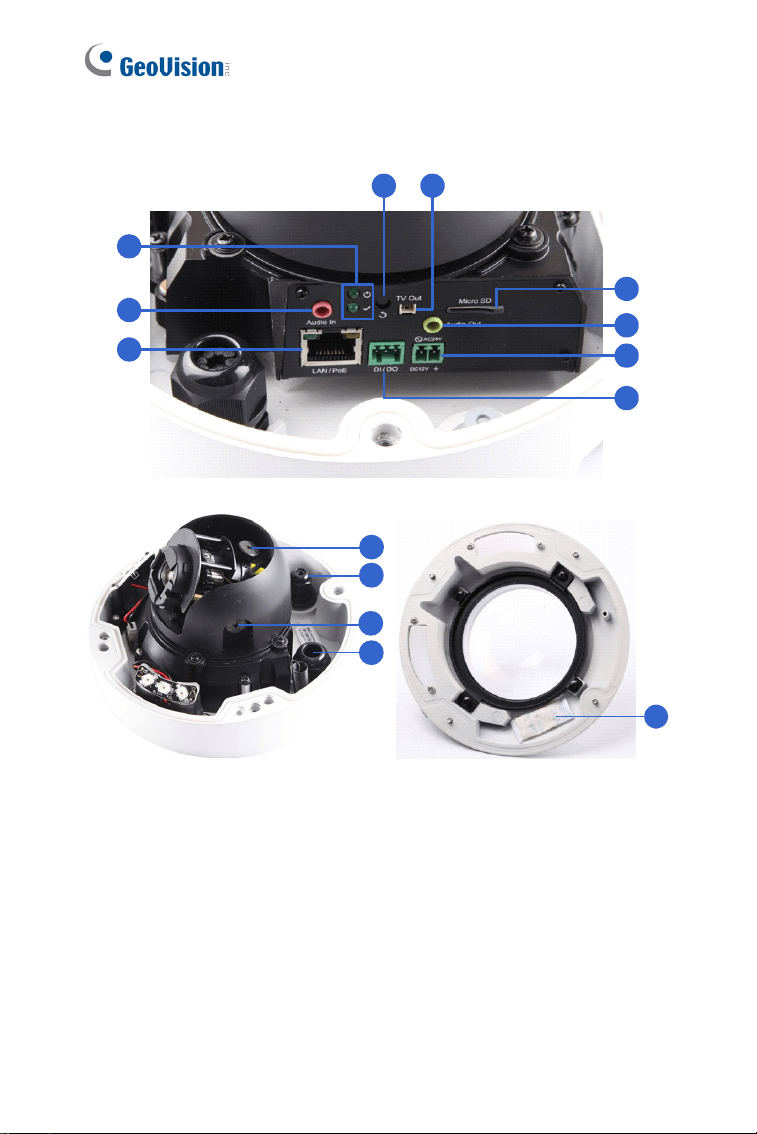
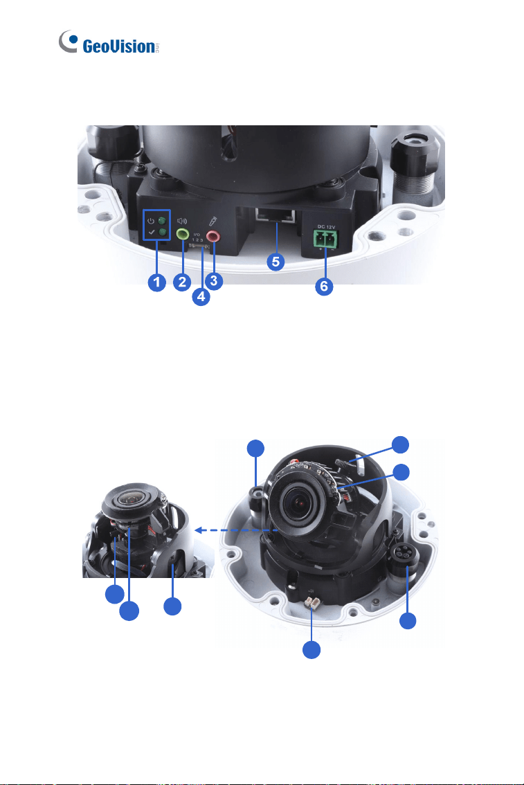
2.2 Overview
1
2
3
4 5
6
8
7
9
10
12
11
13
14
Figure 2-1
Vandal Proof IP Dome (Part II)
27
2
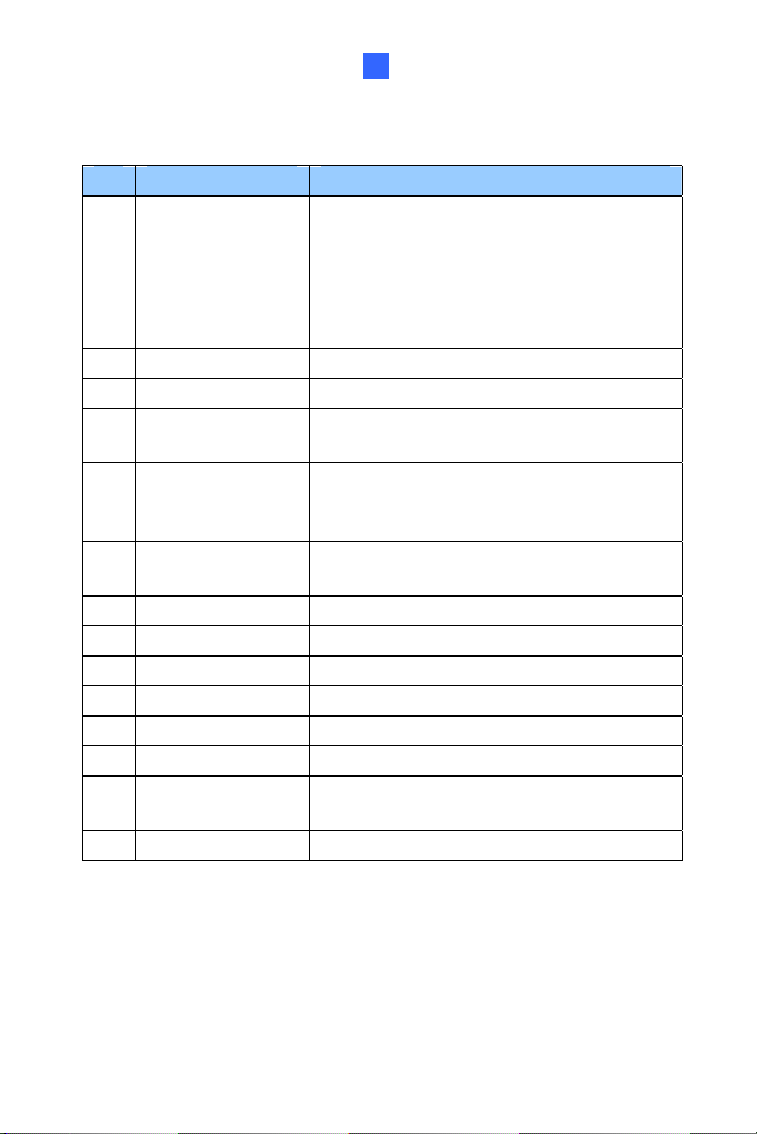
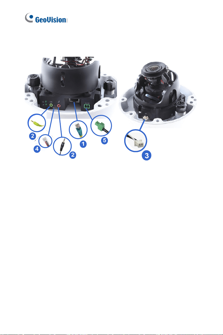
No. Name Description
1 LED Indicators
The power LED (top) turns on (green) when
the power is on and turns off when there is
no power supply. The status LED (bottom)
turns on (green) when the system operates
normally and turns off when system error
occurs.
2 Audio In Connects to a microphone for audio output.
3 LAN / PoE Connects to a 10/100 Ethernet or PoE.
4 Default Button
Resets the camera to factory default. For
details, see 2.5 Loading Factory Default.
5 Video Out
Connects to a portable monitor for setting
the focus and angle of the camera during
initial setup.
6 Memory Card Slot
Inserts a micro SD card (SD/SDHC, version
2.0 only, Class 10) to store recording data.
7 Audio Out Connects to a speaker for audio output.
8 DC 12V / AC 24V Connects to power.
9 I/O Terminal Block Connects to an I/O device.
10 Rotational Screw Loosens to rotate the camera.
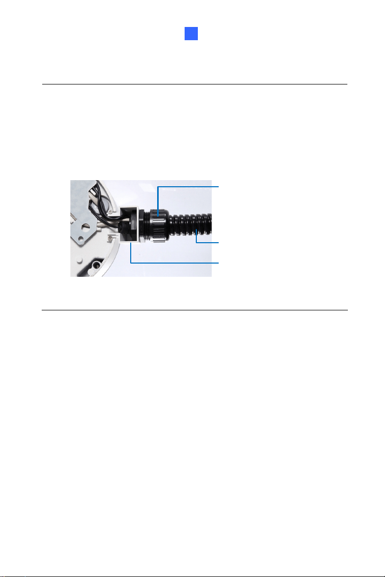
11 Cable Gland Waterproofs the Ethernet cable.
12 Tilt Screw Loosen the screw to tilt the camera.
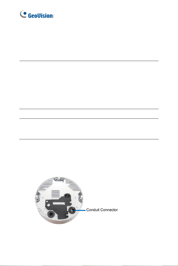
13 Conduit Connector
Waterproofs the audio, TV out, power
adapter and I/O wires.
14 Silica Gel Bag Absorbs moisture in the camera body.
28
2.3 Installation
The Vandal Proof IP Dome is designed for outdoors. With the standard
package, you can install the camera on the ceiling.
Note: You can also install the camera:
on a power box (of the 4" square and double gang type) using the
standard package
to ceilings, wall corners (concave or convex), and poles using
optional mounting kits
For details on these installations, see GV-Mount Accessories Installation
Guide.
IMPORTANT: When installing the Vandal Proof IP Dome near the
corner, maintain at least 25 cm away from the walls to avoid reflection
problems.
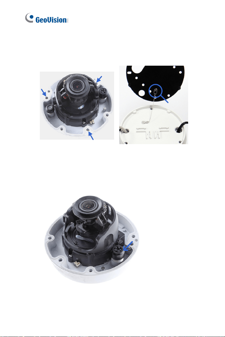
1. Remove the housing cover with the supplied torx wrench.
2. Thread wires into the camera.
A. Unscrew the conduit connector from the back.
Figure 2-2
Vandal Proof IP Dome (Part II)
29
2
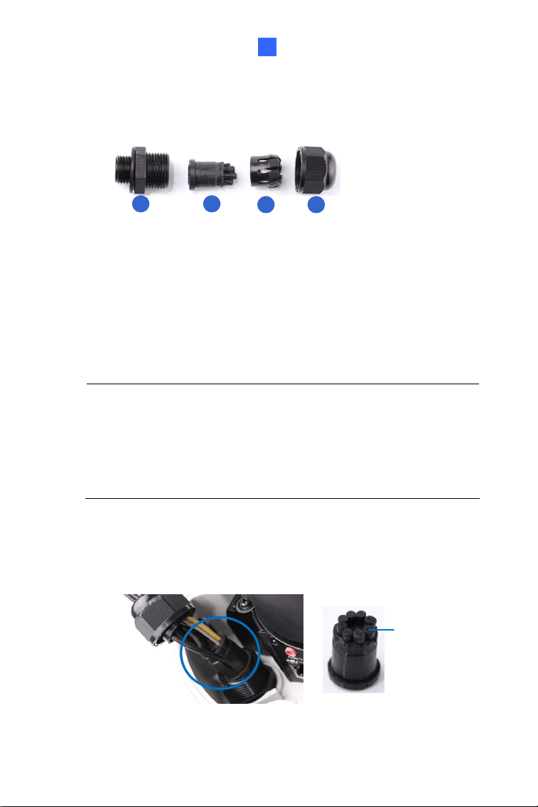
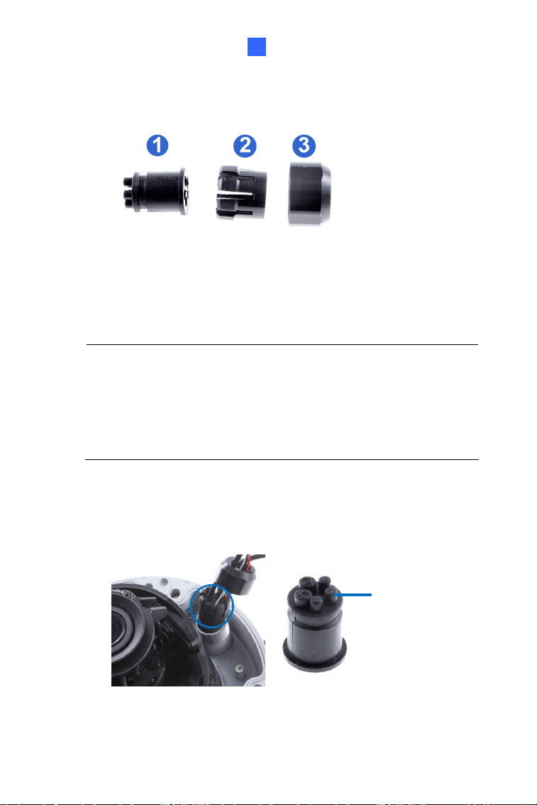
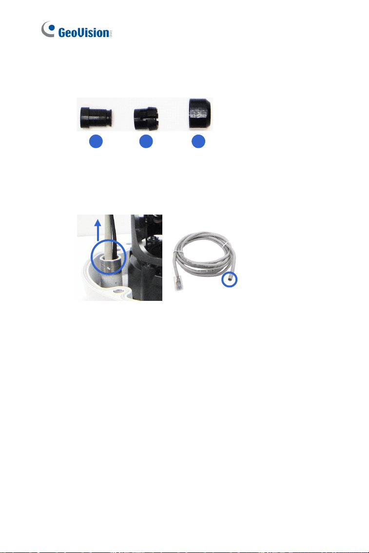
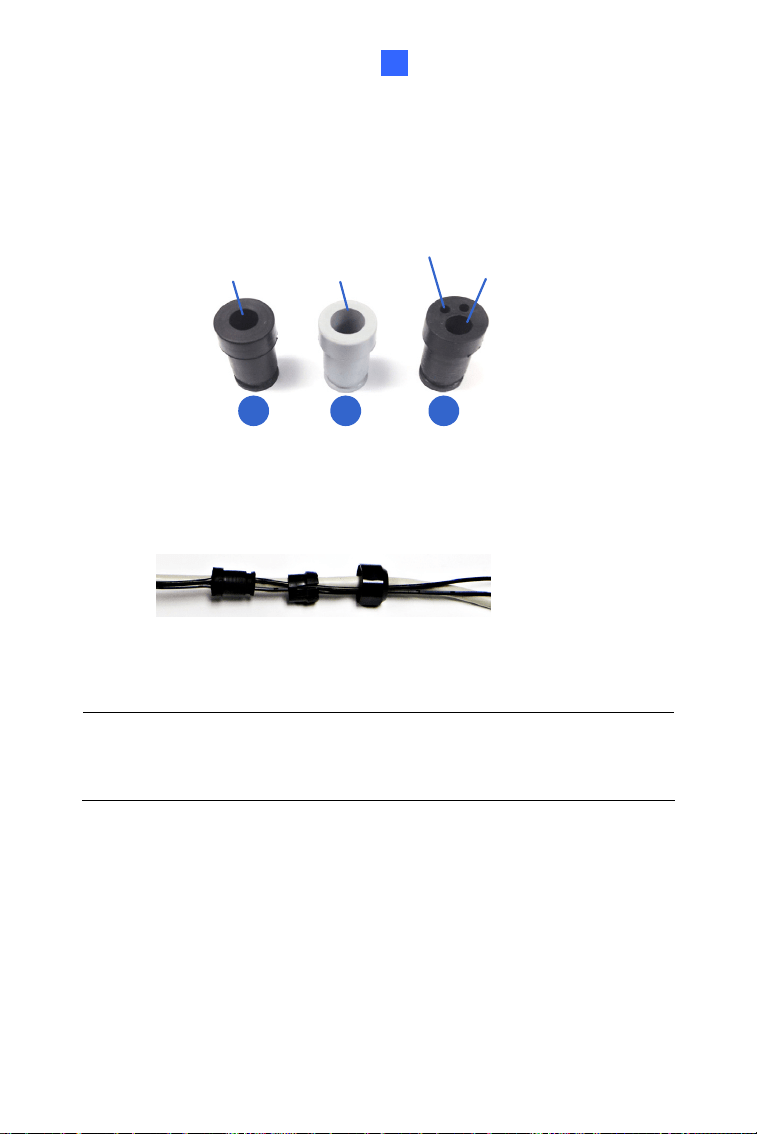
B. Unplug the conduit connector inside the housing and disintegrate
the connector. You should have 4 parts:
1 2
3 4
Figure 2-3
C. Remove the terminal block from the supplied power adapter.
(Power adapter is not supplied for GV-VD4711 / 5711)
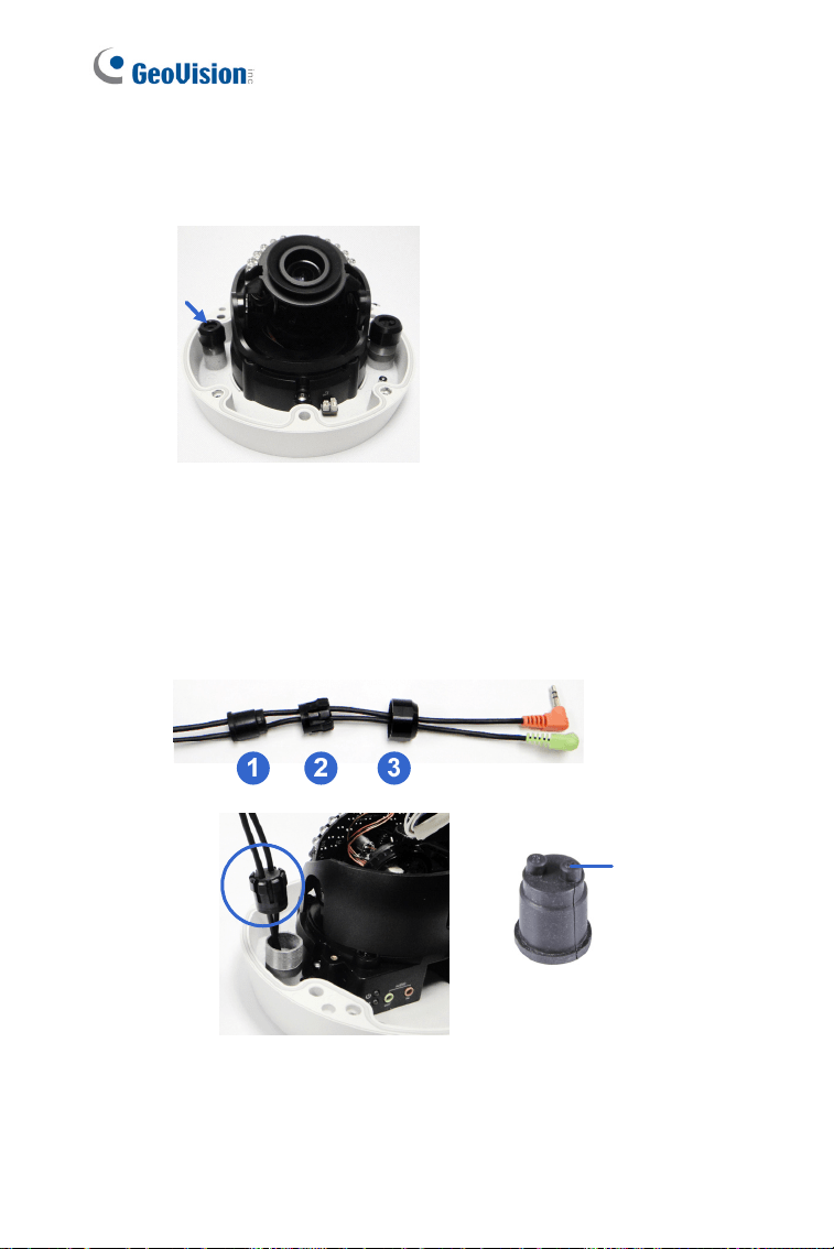
D. Thread the audio wires (optional), TV out wire (optional), adapter
wires and I/O wires (optional) through the conduit entry and then
through part 1, 2, 3 and 4 of the conduit connector.
Tip:
1. To make the threading easier, it is advised to thread the wires
in the order described here.
2. Use a pair of pliers to help you pull the wires through the
camera.
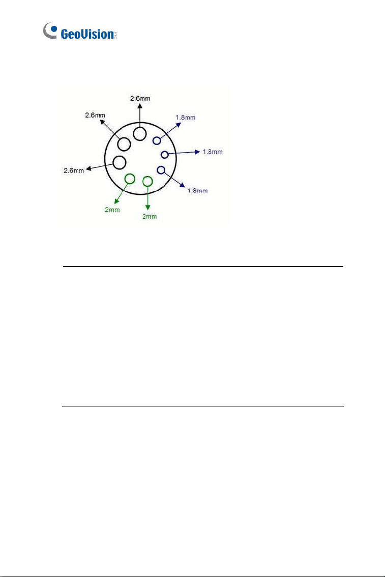
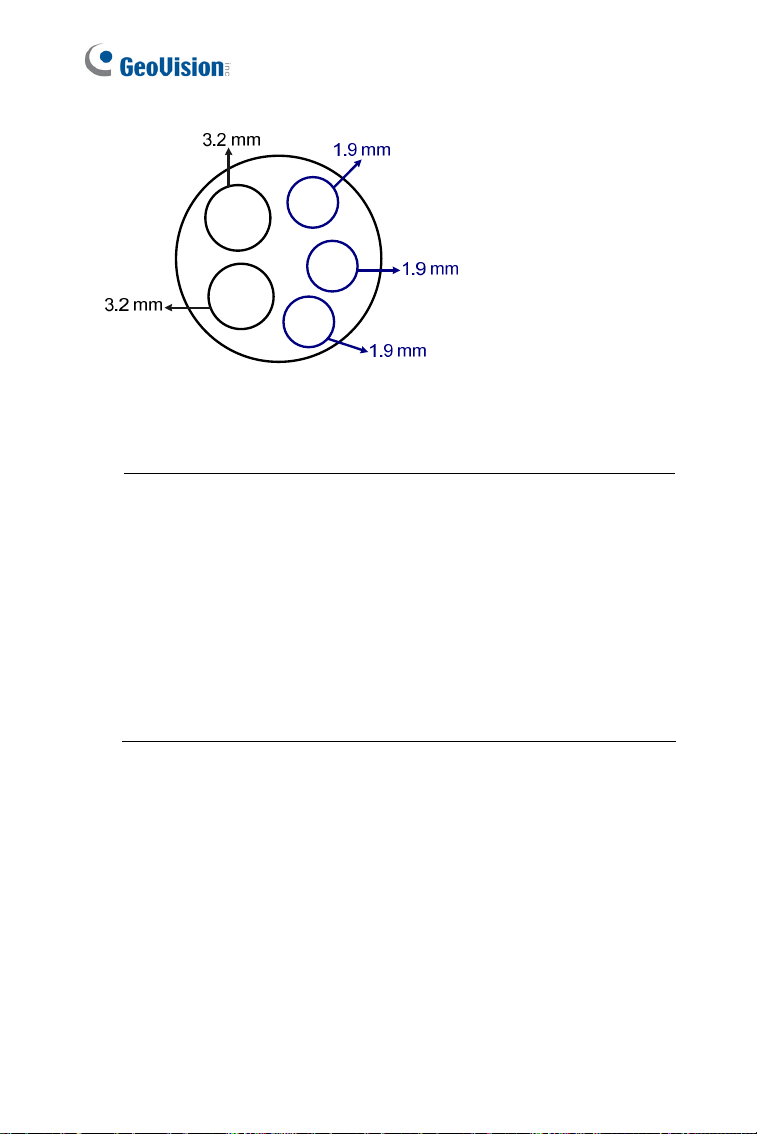
For part 2, there are 8 holes each labeled with its diameter.
Remove the plugs and push the wires to the corresponding hole
listed below:
Plug
Figure 2-4
30
2.6 mm: Audio, BNC
2 mm: DC12V / AC24V
1.8 mm: DIDO
Figure 2-5
IMPORTANT:
1. Use the supplied ruler and leave about 10 cm of power and I/O
wires between their connectors on the camera and the cable
gland; leave at least 11 cm of audio/TV-out wires between their
connectors and the cable gland.
2. The plugs are used to prevent water from entering the camera
housing. Keep the unused holes plugged and save the
removed plugs for future use.
3. Only thread the wires through their designated holes on the
conduit connector to make sure the wires are properly sealed.
Vandal Proof IP Dome (Part II)
31
2
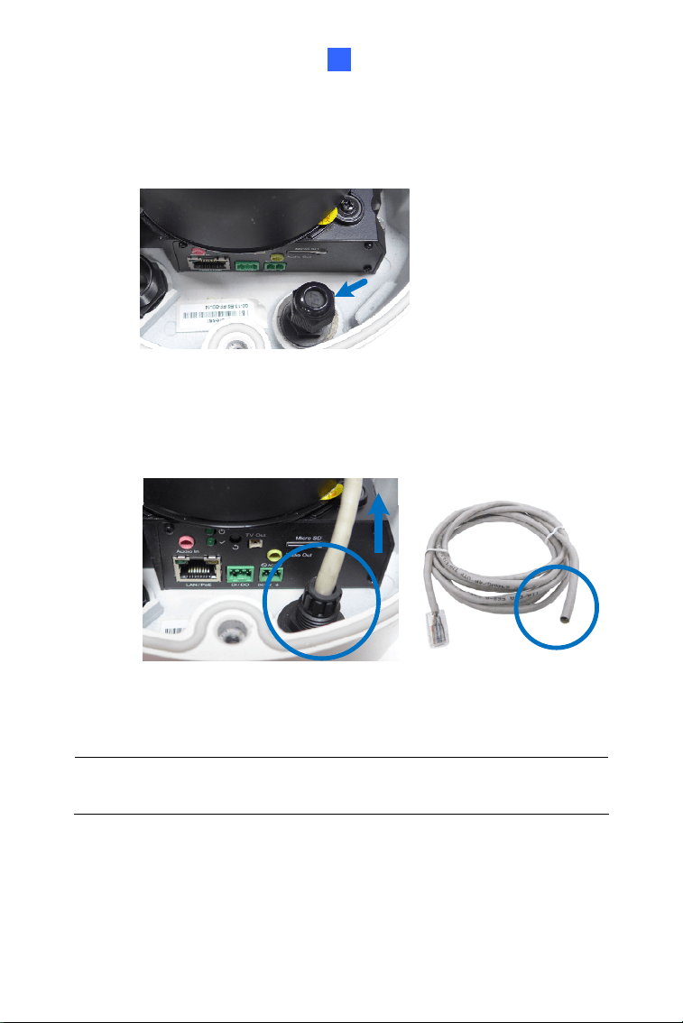
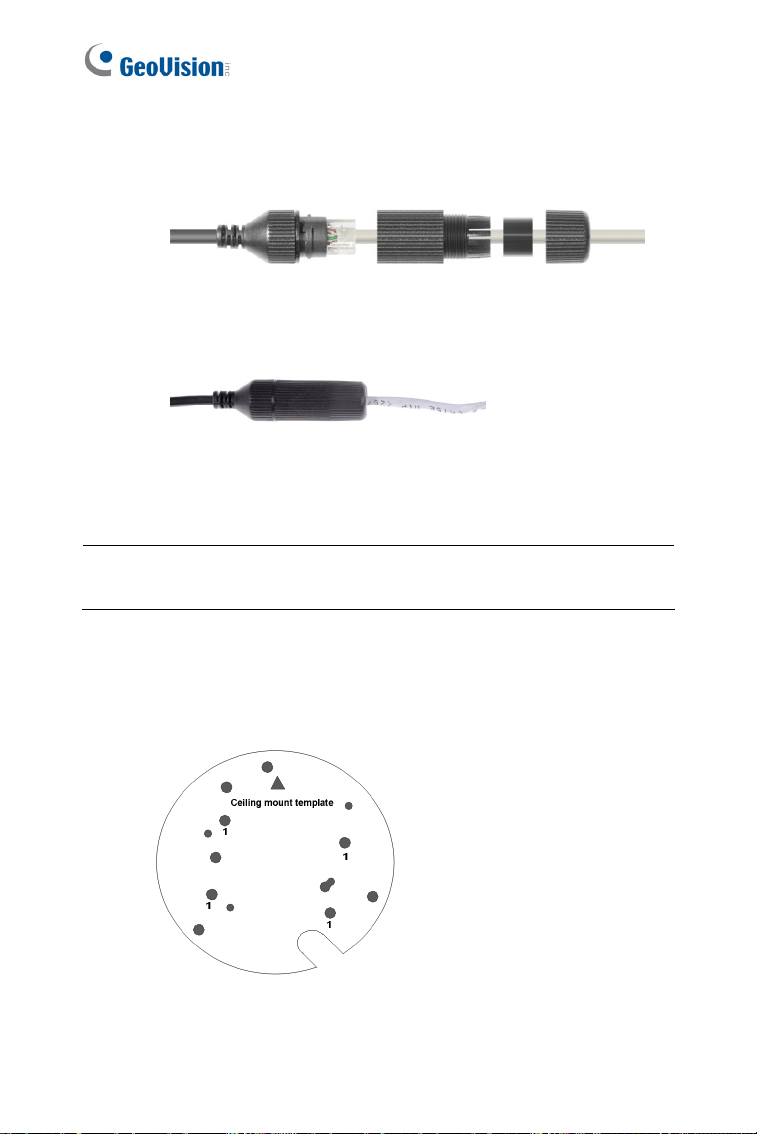
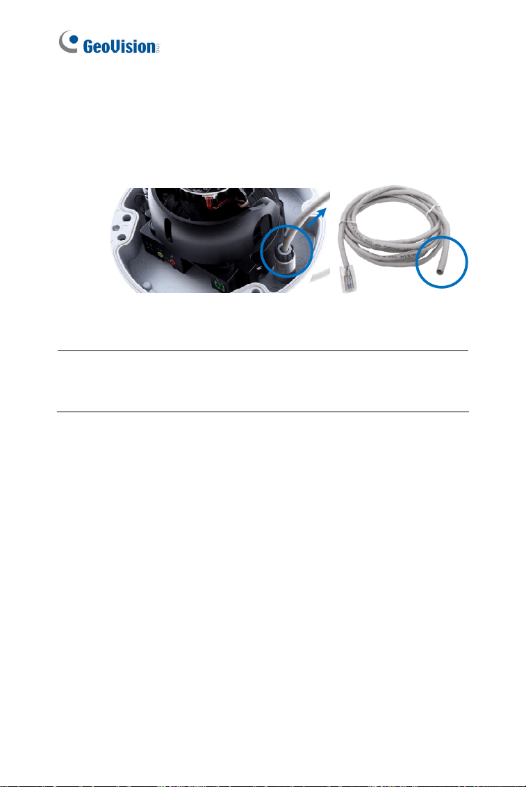
3. Install the Ethernet cable.
A. Rotate to remove the indicated cap and the plug inside.
Figure 2-6
B. Thread an Ethernet cable (the end with no RJ-45 connector) from
the back panel through the cable gland
Figure 2-7
IMPORTANT: Use the supplied ruler and leave about 11 cm of the
Ethernet cable between the connector and the cable gland.
C. Re-install the cap. Make sure the cap is installed tightly to
waterproof the camera.
32
4. Connect the wires to the camera.
A. Install the terminal blocks to the power adapter and I/O devices.
See 2.4.1 Power Connection and 2.4.2 I/O Device Connections.
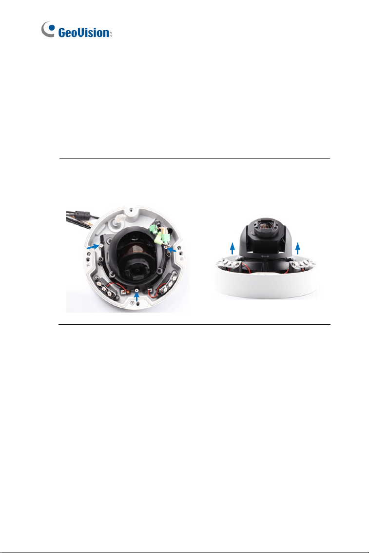
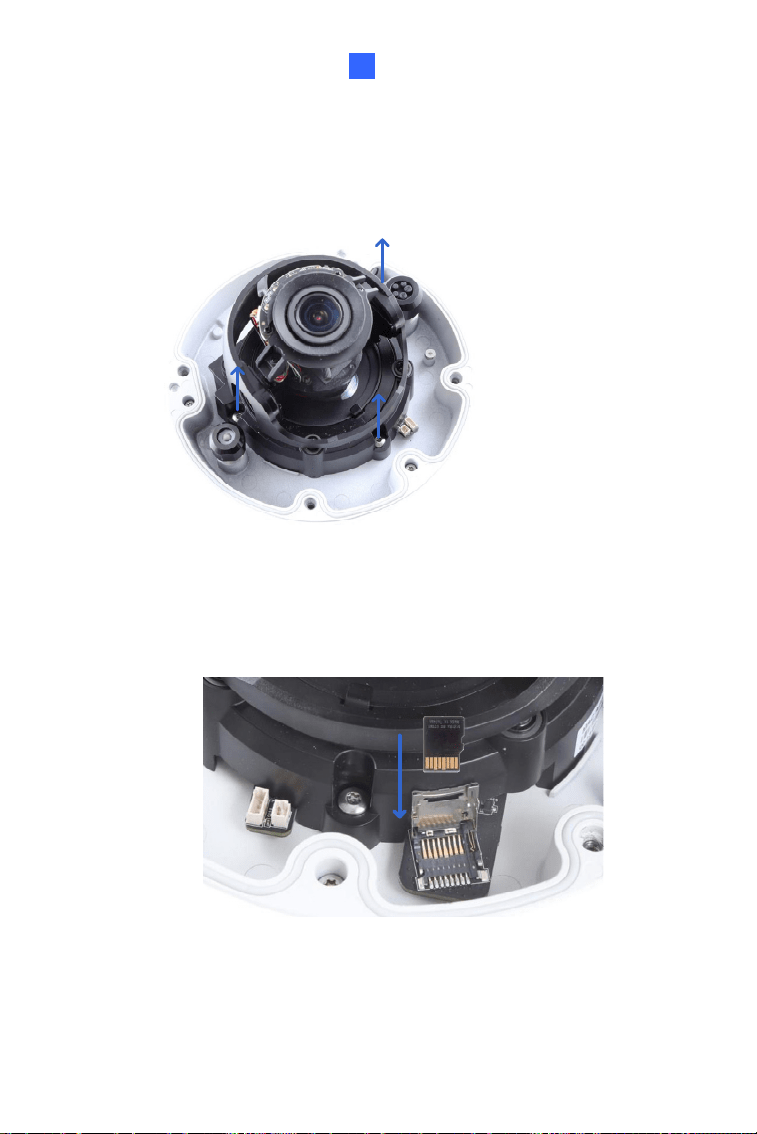
B. Install the supplied RJ-45 connector to the Ethernet cable.
C. Plug all the connectors to the camera panel.
Tip: Unscrew the indicated screws and lift the camera to help you
connect the wires.
D. Arrange the wires in the conduit connector and re-install it to the
camera.
Vandal Proof IP Dome (Part II)
33
2
5. Sort out the wires at the back. You can have the wires come out from
position A, B or both. The instructions here describe sorting wires for
position A.
A
B
Figure 2-8
From the back of the camera housing, unscrew and rotate the plate to
one side, sort out the wires and secure the plate back.
Plate
Figure 2-9
34
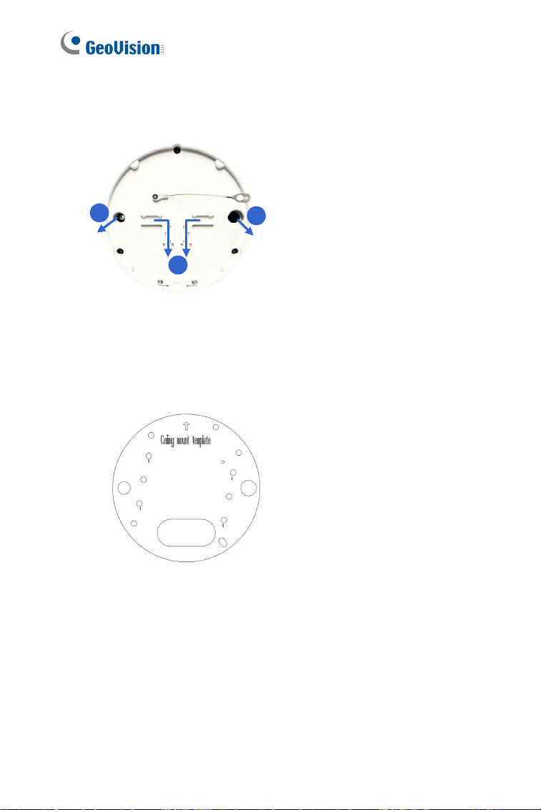
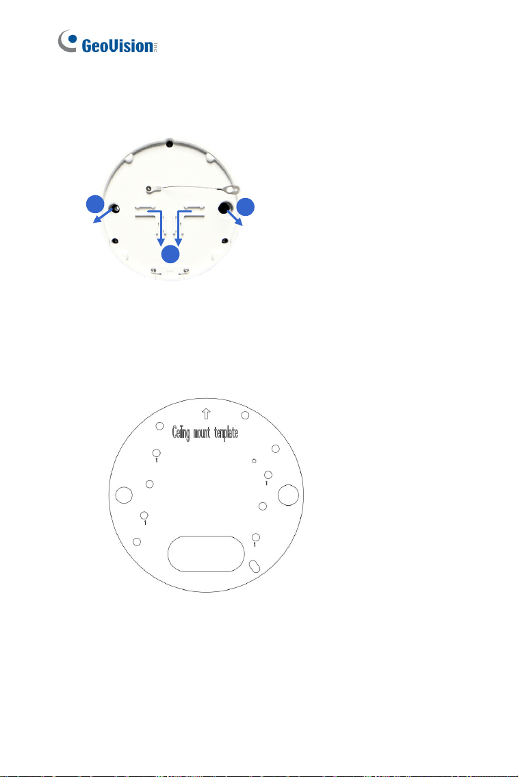
6. Secure the back plate to the ceiling.
A. Paste the sticker to the ceiling. The arrow on the sticker indicates
the direction that the camera faces.
1
1
1
Ceiling mount template
A
B
Figure 2-10
B. Drill 3 holes for screws. The recommended ones are indicated as
‘1’.
C. Insert the screw anchors to the 3 holes.
D. Depending on how you want to run the wires (see step 5). Drill
the right hole (Figure 2-10) for position A and the left for position
B or both if required.
E. Secure the back plate to the ceiling with long screws.
Vandal Proof IP Dome (Part II)
35
2
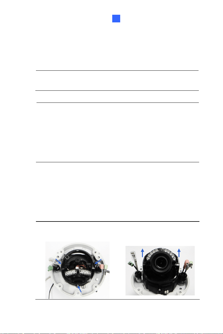
7. Secure the camera to the ceiling.
A. Secure the safety lock to the camera using a short screw. Use
flat screw for number 1 and small screw for number 2.
1
2
Figure 2-11
B. Thread all the wires into the ceiling and connect them.
C. Secure the camera using the torx wrench.
Figure 2-12
36
8. Access the live view. See 6.2 Accessing the Live View.
9. Adjust the camera’s angle, focus and zoom of the camera.
Pan Adjustment
Tilt Adjustment
Rotational Adjustment
Figure 2-13
10. Replace the silica gel bag and secure the camera cover using the torx
wrench.
Vandal Proof IP Dome (Part II)
37
2
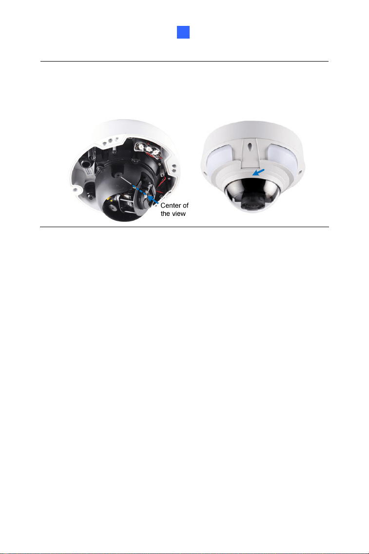
IMPORTANT:
If the center of the camera view is less than 25° to the
ceiling, or lower than the grey line (as illustrated below), disassemble
the indicated ring so the view is not obstructed. However, with the ring
disassembled, slight reflections may occur.
38
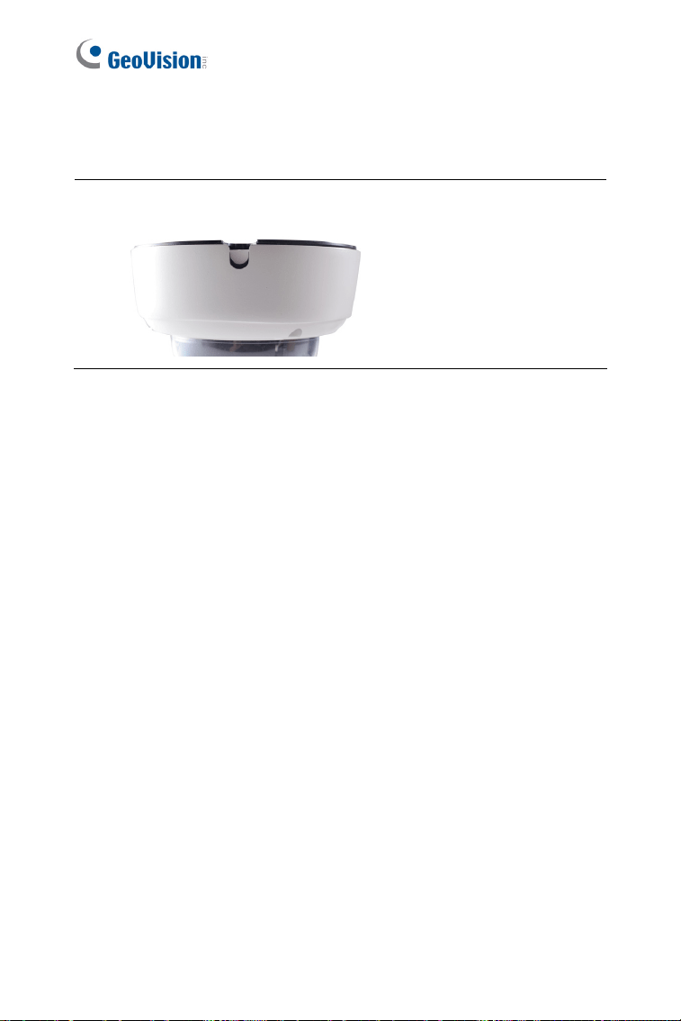
2.3.1 Installation of Weatherproof Shield
Optionally purchase a weatherproof shield to protect the camera from rain
and snow.
Note: A weatherproof shield can be purchased upon request. The pan
and tilt angle of the camera is limited by the shield.
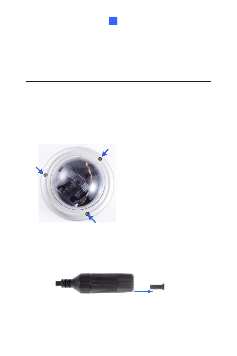
1. Remove the housing cover.
2. Remove the three screws from the housing cover.
3. Secure the three screws of the weatherproof shield to the housing
cover.
Weatherproof Shield
Figure 2-14
Vandal Proof IP Dome (Part II)
39
2
2.4 Connecting the Camera
Connect your Vandal Proof IP Dome to power, network and other wires
needed.
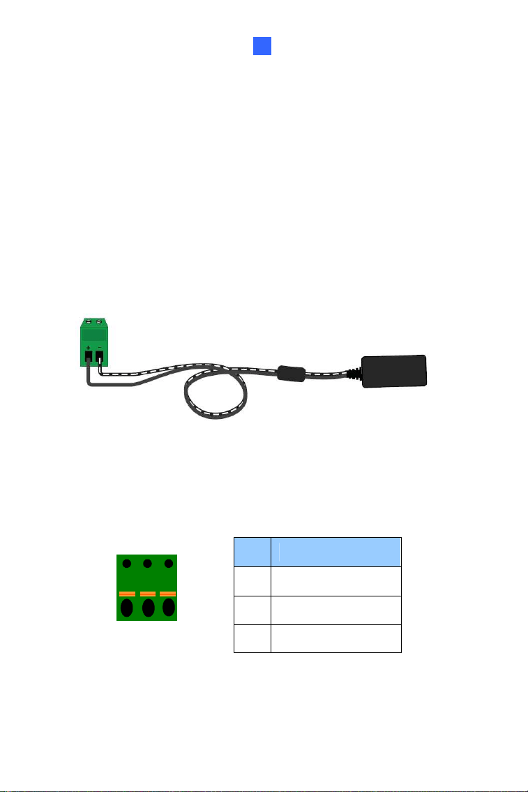
2.4.1 Power Connection
There are two ways to supply power to the camera:
Use a Power over Ethernet (PoE) adapter to connect the camera to the
network, and the power will be provided at the same time.
Plug the power adapter to the terminal block by inserting the striped
wire to the right pin (-) and the black wire to the left pin (+).
Figure 2-15
2.4.2 I/O Device Connections
The camera supports one digital input and one digital output of dry contact.
Pin Function
1 Digital Output
2 GND
I/O
1
2
3
Figure 2-21
3 Digital Input
For details on how to enable an installed I/O device, see 4.3 I/O Settings,
GV-IPCam Firmware Manual.
40
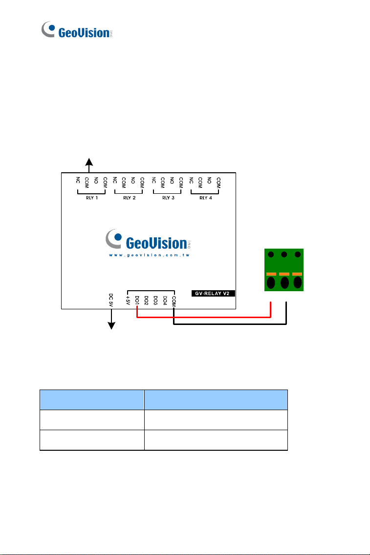
2.4.3 Voltage Load Expansion (Optional)
The camera can only drive a maximum load of 200mA 5V DC. To expand
the maximum voltage load to
10A 250V AC, 10A 125V AC or 5A 100V DC,
connect the camera to a GV-Relay V2 module (optional product). Refer to
the figure and table below.
Output Devices
Connect to Power
I/O
123
Figure 2-16
GV-Relay V2 Vandal Proof IP Dome
COM Pin 2 of I/O terminal block
DO1 Pin 1 of I/O terminal block
Vandal Proof IP Dome (Part II)
41
2
2.5 Loading Factory Default
2.5.1 Using the Web Interface
You can restore factory default settings through the Web interface. For
details, refer to 1.5.1 Using the Web Interface.
2.5.2 Directly on the Camera
Use a pin to press and hold the default button for about 8 seconds.
Release the default button when the status LED blinks. For details, see
1.5.2 Directly on the Camera.
Figure 2-17
42
Chapter 3 Vandal Proof IP Dome
(Part III)
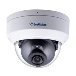
These Vandal Proof IP Domes are outdoor cameras equipped with a
removable IR-cut filter for optimal day and night surveillance. The cameras
adhere to IK10 vandal resistance and IP67 ingress protection. They can
support H.265 video codec to achieve better compression ratio while
maintaining high quality picture. For night operations, the cameras allow up
to 30 m (98.4 ft) effective IR distance. All models have P-Iris for precise
control of exposure and better image clarity and contrast. The Super Low
Lux model, featuring Wide Dynamic Range Pro (WDR Pro), provides clear
live views not only in near darkness but also under contrasting light
intensities. Adjustable in 3 axis (pan, tilt and rotate), the cameras offer
effective surveillance solution with all the essential features and excellent
image quality.
Model No. Specifications Description
GV-VD3700
P-Iris,
f:3 ~ 9 mm,
F/1.7, 1/2.7”
ø 14 mm lens mount
3 MP H.265,
WDR Pro, Super
Low Lux
GV-VD5700
Varifocal
lens
P-Iris,
f:4 ~ 8 mm, F/1.65,
1/1.8”
ø 14 mm lens mount
5 MP H.265,
WDR, Low Lux
Vandal Proof IP Dome (Part III)
43
3
3.1 Packing List
H.265 Vandal Proof IP Dome
Torx Wrench
Long Screw x 4
Screw Anchor x 4
Back Plate
Short Screw (for Back
Plate) x 3
Installation sticker
RJ-45 Connector x 2
Cable Stopper
Anti-Drop Wire
44
Screw (for the Anti-Drop Wire)
Silica Gel Bag x 2
Sticker (for Silica Gel Bag) x 2 Pan Angle Notification Card
Download Guide Warranty Card
Note: The supplied anti-drop wire is used for attaching the camera body
to GV-Mount206. For more details, see GV-Mount Accessories
Installation Guide.
Vandal Proof IP Dome (Part III)
45
3
3.2 Overview
1
2
4
5
3
Figure 3-1
46
No. Name Description
1 Rotational Screw Loosen to rotate the lens.
2 SD Card Slot
Insert a micro SD card (SD/SDHC/SDXC/
UHS-I, Class 10) to store recording data.
* UHS-II card type is not supported.
3 Base Screw Loosen to pan the camera.
4 Tilt Screw Loosen to tilt the camera.
5 Default Button
Reset the camera to factory default. For
details, see 3.5 Loading Factory Default.
Vandal Proof IP Dome (Part III)
47
3
3.3 Installation
The Vandal Proof IP Dome is designed for outdoors. With the standard
package, you can install the camera on the ceiling.
Note: You can also install the camera to ceilings, wall corners (concave
or convex), and poles using optional mounting kits.
For details on these installations, see GV-Mount Accessories Installation
Guide .
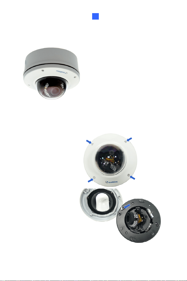
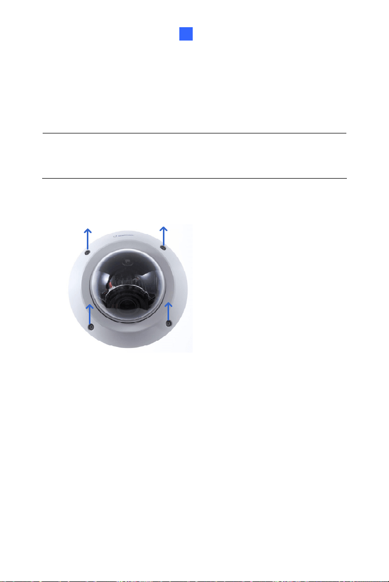
1. Remove the housing cover with the supplied torx wrench.
Figure 3-2
2. Thread the Ethernet cable into conduit connector.
A. Remove the plug from the conduit connector.
Figure 3-3
48
B. Disintegrate the removed conduit connector. Thread the
Ethernet cable through the 3 parts.
Figure 3-4
C. Assemble the conduit connector.
Figure 3-5
Note: If you can’t plug the self-prepared RJ-45 connector into the jack of
the conduit, it is suggested to use the supplied RJ-45 connector.
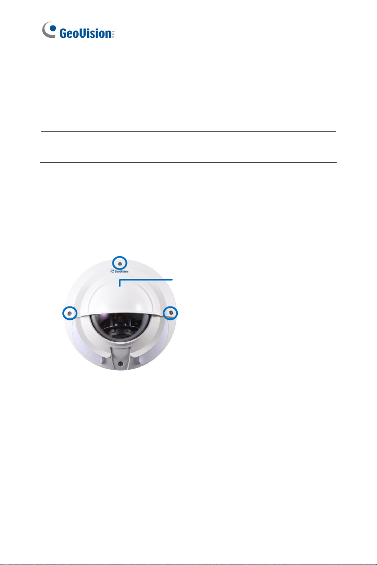
3. Secure the back plate to the ceiling.
A. Paste the sticker to the ceiling. The triangle on the sticker
indicates the direction that the camera faces.
Figure 3-6
Vandal Proof IP Dome (Part III)
49
3
B. Drill 4 holes for screws. The recommended ones are indicated as
‘1’.
C. Insert the screw anchors to the 4 holes on the ceiling.
D. Secure the back plate to the ceiling with 4 long screws.
E. Align and secure the back plate to the rear side of the camera
with the supplied short screws.
Figure 3-7
4. Insert your micro SD card into the SD card slot.
Figure 3-8
5. Access the live view. See 6.2 Accessing the Live View.
50
6. Based on the live view, adjust the camera’s angle, focus and zoom.
Pan Adjustment
Figure 3-9
IMPORTANT:
1. Loosen the screw indicated below before adjusting the camera pan
angle.
2. The front of the camera is marked with a white line in front of the
memory card slot. When adjusting the camera pan angle, avoid
turning the camera for more than 180 degrees in either direction.
Continuous rotation greater than 180 degrees could pull off the
internal cable and cause the camera to malfunction.
Vandal Proof IP Dome (Part III)
51
3
Tilt Adjustment
Rotational Adjustment
Figure 3-10
7. Paste the silica gel bag with a sticker right behind the lens.
Figure 3-11
52
8. Secure the housing cover back to the camera body.
Note:
You can remove the cable stopper to thread the camera’s cable
through the side opening.
Vandal Proof IP Dome (Part III)
53
3
3.4 Connecting the Camera
Connect your camera to power, network and other cables needed.
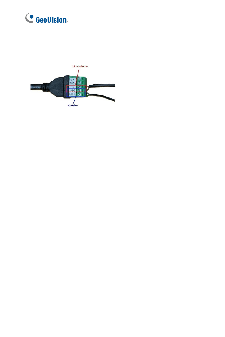
3.4.1 Definition
Figure 3-12
Pin Wire Name Definition
1 DO + Digital out +
2 DO - Digital out -
3 DI + Digital in +
4
4-Pin terminal
block
DI - Digital in -
5 L – Out Audio out
6 A GND Audio ground
7 L – IN
Audio in
*Support passive microphones only
8 GND DC 12 V +
9
5-Pin terminal
block
12 V DC 12 V -
Wire Definition
RJ-45 Ethernet or PoE
54
Note: To connect an audio input/output device, cut its 3.5 mm audio jack,
and connect the wires to
L-IN and A GND for a microphone or L-OUT and
A GND for a speaker.
Figure 3-13
For details on how to enable an installed I/O device, see 4.3 I/O Settings,
GV-IPCam Firmware Manual.
Vandal Proof IP Dome (Part III)
55
3
3.4.2 Power Connection
There are two ways to supply power to the camera:
Use a Power over Ethernet (PoE) adapter to connect the camera to
the network, and the power will be provided at the same time.
Connect the wires of your power adapter to the DC 12V+ and DC
12V- to the 5-pin terminal blocks.
Figure 3-14
56
3.4.3 Voltage Load Expansion (Optional)
The camera can only drive a maximum load of 200mA 5V DC. To expand
the maximum voltage load to
10A 250V AC, 10A 125V AC or 5A 100V DC,
connect the camera to a GV-Relay V2 module (optional product). Refer to
the figure and table below.
Figure 3-15
GV-Relay V2 Vandal Proof IP Dome
COM Digital in + & Digital out +
DO1 Digital out -
Vandal Proof IP Dome (Part III)
57
3
3.5 Loading Factory Default
3.5.1 Using the Web Interface
You can restore factory default settings through the Web interface. For
details, refer to 1.5.1 Using the Web Interface.
3.5.2 Directly on the Camera
Insert a thin object into the default button next to the camera lens. Press
and hold the default button for about
5 seconds to load the factory default.
For details, see 1.5.2 Directly on the Camera.
Figure 3-16

58
Chapter 4 Vandal Proof IP Dome
(Part IV)
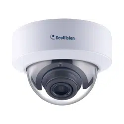
These Vandal Proof IP Domes are outdoor cameras equipped with a
removable IR-cut filter for optimal day and night surveillance. The cameras
adhere to IK10 vandal resistance and IP67 ingress protection. They can
support H.265 video codec to achieve better compression ratio while
maintaining high quality picture. For night operations, the cameras allow up
to 30 m (98.4 ft) effective IR distance. Adjustable in 3 axis (pan, tilt and
rotate), the cameras offer effective surveillance solution with all the
essential features and excellent image quality.
For GV-VD2702 / 2712 / 4702 / 4712, with their super low lux CMOS image
sensor and WDR Pro, the cameras are capable of providing a color live
view in near darkness, and also under contrasting light intensities.
For GV-VD2712 / 4712, with its motorized varifocal lens, the user can
zoom and focus the camera from the Web interface.
Vandal Proof IP Dome (Part IV)
59
4
Model No. Specifications Description
GV-VD2702
Varifocal
lens
P-Iris,
f:2.8 ~ 12 mm,
F/1.7, 1/2.7”
ø 14 mm lens
mount
2 MP H.265,
WDR Pro, Super
Low Lux
GV-VD2712
Motorized
varifocal lens
P-Iris,
f:2.8 ~ 12 mm,
F/1.2, 1/2.7”
ø 14 mm lens
mount
2 MP H.265,
WDR Pro, Super
Low Lux
GV-VD4702
Varifocal
lens
P-Iris,
f:2.8 ~ 12 mm,
F/1.7, 1/2.7”
ø 14 mm lens
mount
4 MP H.265,
WDR Pro, Super
Low Lux
GV-VD4712
Motorized
varifocal lens
P-Iris,
f:2.8 ~ 12 mm,
F/1.4, 1/2.7”
ø 14 mm lens
mount
4 MP H.265,
WDR Pro, Super
Low Lux
60
4.1 Packing List
H.265 Vandal Proof IP Dome
Torx Wrench
Screw x 4
Screw Anchor x 4
TV-Out Wire
Audio Wire x 2
I/O Cable
Installation sticker
Conduit Converter
RJ-45 Connector
Vandal Proof IP Dome (Part IV)
61
4
PG21 Conduit Connector
Waterproof Rubber Sets
(for RJ-45 Cat.5 and 12V
DC / for RJ-45 Cat.6)
Cat.6
(Ø 6 mm)
Cat.5
(Ø 5 mm)
Big Concave Hexagon
Wrench
Small Concave Hexagon
Wrench
Silica Gel Bag Sticker (for Silica Gel Bag)
Ruler Download Guide
Warranty Card
62
4.2 Overview
Figure 4-1
13
12
10
7
8
9
11
14
Figure 4-2
Vandal Proof IP Dome (Part IV)
63
4
GV-VD2702 / 2712
Figure 4-3
GV-VD4702 / 4712
Figure 4-4
64
No. Name Description
1 LED Indicators
The power LED (top) turns on (green)
when the power is on and turns off when
there is no power supply. The status LED
(bottom) turns on (green) when the
system operates normally and turns off
when system error occurs.
2 Audio Out Connects to a speaker for audio output.
3 Audio In
Connects to a microphone for audio
input.
4 I/O Connector
Connects to I/O devices. For details, See
4.5 I/O Connector.
5 LAN / PoE Connects to a 10/100 Ethernet or PoE.
6 DC 12V Connects to power.
7 Default Button
Resets the camera to factory default. For
details, see 4.6 Loading Factory Default.
8 Rotational Screw Loosens to rotate the camera.
9 Tilt Screw Loosens the screw to tilt the camera.
10 TV-Out
Provides video input (D1 resolution) for a
monitor.
11 Conduit Connector Waterproofs the audio / I/O wires.
12 Cable Gland Waterproofs the Ethernet cable.
13 Zoom Screw Adjusts the zoom of the camera.
14 Focus Screw Adjusts the focus of the camera.
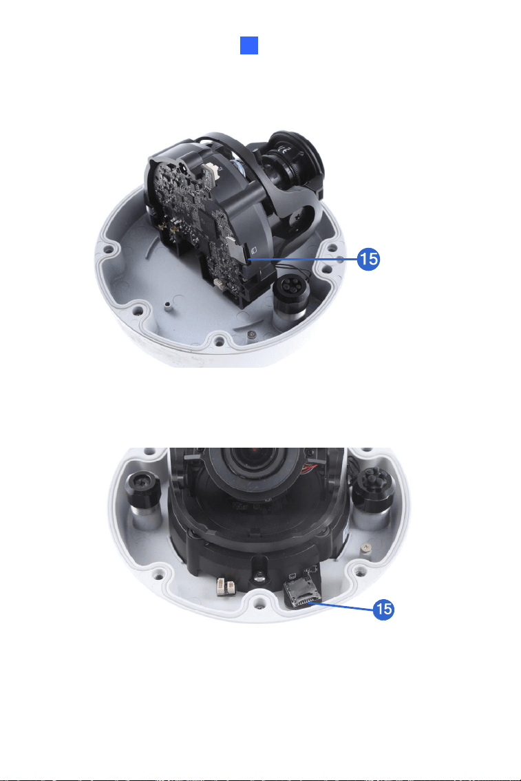
15 Memory Card Slot
Inserts a micro SD card
(SD/SDHC/SDXC/UHSI, Class 10) to
store recording data. For details, see 4.3
Installation
Vandal Proof IP Dome (Part IV)
65
4
4.3 Installation
The Vandal Proof IP Dome is designed for outdoors. With the standard
package, you can install the camera on the ceiling.
Note: You can also install the camera to ceilings, wall corners (concave
or convex), and poles using optional mounting kits. For details on these
installations, see GV-Mount Accessories Installation Guide.
1. Remove the housing cover with the supplied torx wrench.
Figure 4-5
66
2. Remove the back plate with the supplied torx wrench and remove the
safety lock with a Philips screwdriver. Keep the removed screw for
later use.
Safety lo
c
Figure 4-6
3. Thread wires into the camera.
A. Rotate to remove the cap of the conduit connector.
Figure 4-7
Vandal Proof IP Dome (Part IV)
67
4
B. Unplug the conduit connector inside the housing and disintegrate
the connector. You should have 3 parts:
Figure 4-8
C. Thread the audio wires and I/O wires through the conduit entry
and then through part 1, 2, and 3 of the conduit connector.
Tip:
1. To make the threading easier, it is advised to thread the wires
in the order described here.
2. Use a pair of pliers to help you pull the wires through the
camera.
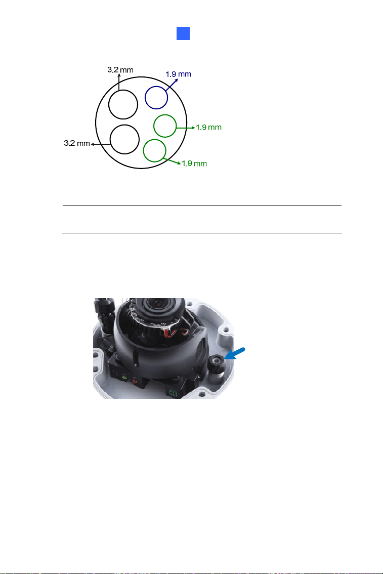
For part 1, there are 5 holes each labeled with its diameter.
Remove the plugs and push the wires to the corresponding hole
listed below:
Plug
Figure 4-9
68
3.2 mm: Audio
1.9 mm: DIDO
Figure 4-10
IMPORTANT:
1. Use the supplied ruler and leave at least 14 cm of I/O wires
and 10 cm of audio wires between their connectors on the
camera and the cable gland.
2. The plugs are used to prevent water from entering the
camera housing. Keep the unused holes plugged and save
the removed plugs for future use.
3. Only thread the wires through their designated holes on the
conduit connector to make sure the wires are properly sealed.
If you use cat 6 Ethernet cable, you need to thread the DC 12V
wires through the conduit connector. Followings are the
corresponding holes.
Vandal Proof IP Dome (Part IV)
69
4
Figure 4-11
3.2 mm: Audio
1.9 mm: DIDO
1.9 mm: DC 12V
IMPORTANT: Leave more than 10 cm of power wires between
their connectors on the camera and the cable gland.
4. Install the Ethernet cable.
A. Rotate to remove the indicated cap and the plug inside.
Figure 4-12
70
B. Thread an Ethernet cable (the end with no RJ-45 connector) and
the optional power adapter wires from the back panel through the
cable gland
Figure 4-13
IMPORTANT: Use the supplied ruler and leave about 14 cm of the
Ethernet cable between the connector on the camera and the cable
gland.
C. Re-install the cap. Make sure the cap is installed tightly to
waterproof the camera.
5. Connect the wires to the camera.
A. Install the terminal blocks to the power adapter and I/O devices.
See 4.4 Connecting the Camera and 4.5 I/O Connector.
B. Install the supplied RJ-45 connector to the Ethernet cable.
C. Plug all the connectors to the camera panel.
D. Arrange the wires in the conduit connector and re-install it to the
camera.
Vandal Proof IP Dome (Part IV)
71
4
6. Insert the memory card to the memory card slot.
A. For
GV-VD2702 / 2712, unscrew the indicated screws and lift the
camera to help you insert the memory card.
Figure 4-14
B. For
GV-VD4702 / 4712 :
(1) Pull and lift the cover of the memory card slot, and insert
the memory card into the slot.
Figure 4-15
(2) Press down the cover and push the cover back.
72
7. Sort out the wires at the back. You can have the wires come out from
position A and B or from C.
A
B
C
Figure 4-16
8. Secure the back plate to the ceiling.
A. Paste the sticker to the ceiling. The arrow on the sticker indicates
the direction that the camera faces.
Figure 4-17
B. Drill 4 holes for screws. The recommended ones are indicated as
‘1’.
C. Insert the screw anchors to the 4 holes.
D. Drill A & B holes or only C hole for sorting out the wires according
to Figure 4-16
E. Secure the back plate to the ceiling with the supplied screws.
Vandal Proof IP Dome (Part IV)
73
4
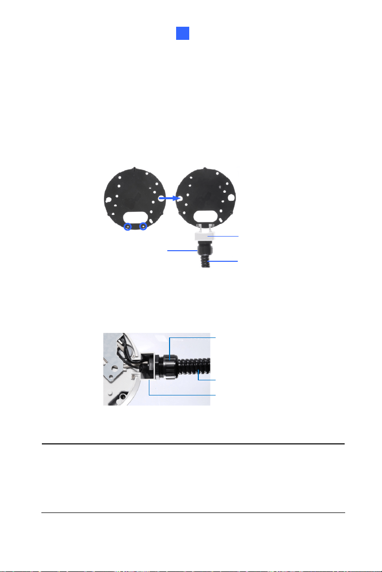
F. To optionally install a pipe, use one of the two methods illustrated
below depending on the type of the back plate that comes with
your camera:
If your plate comes with two knobs (as in Figure 4-18),
install the supplied conduit converter, with the PG21 conduit
connector and a self-prepared 1/2" conduit pipe, to the back
plate.
Conduit
Converter
Plastic PG21 Conduit
Connector
Conduit
Pipe
Figure 4-18
If your plate comes without knobs, install the supplied
conduit connector kit and a self-prepared 1/2" conduit pipe,
to the camera after all the wires are threaded.
Conduit pipe
Conduit converter
Plastic PG21
conduit connector
Figure 4-19
Note:
When installed with a pipe, it is required to supply power through a
PoE adapter because the power adapter wire does not fit in a 1/2” pipe.
You will have to purchase your own PG21 conduit connector if you want
to use 3/4” or 1” pipe.
A metal PG21 conduit connector can be
purchased upon request, which can be connected to a 3/4” pipe.
74
9. Secure the camera to the ceiling.
A. Secure the safety lock to the camera with the screw you
removed from the back plate in step 2.
Safety lock
Figure 4-20
B. Thread all the wires into the ceiling and connect them.
C. Secure the camera to the back plate with the torx wrench.
10. Access the live view. See 6.2 Accessing the Live View.
Note: The TV-out function can be used to access the live view. For
details, see Note for TV-out Function at the beginning of the quick start
guide.
Vandal Proof IP Dome (Part IV)
75
4
11. Adjust the camera’s angle, focus and zoom of the camera.
Pan Adjustment
Tilt Adjustment
Rotational Adjustment
Figure 4-21
12. Replace the silica gel bag, press all the wires and cables into the
notch and secure the camera cover with the torx wrench.
Figure 4-22
76
4.4 Connecting the Camera
Figure 4-23
1. Use a standard network cable to connect the camera to your network.
2. Optionally connect a speaker and an external microphone.
3. Optionally connect a monitor using a Video Out wire. Enable this
function by selecting your signal format at the
TV Out field on the
Web interface. See 4.1.1 Video Settings, GV-IPCam Firmware
Manual.
4. Optionally connect to input / output devices. For details, see 4.5 I/O
Connector.
5. Connect power using one of the following methods:
Plug the power adapter to power port.
Use the Power over Ethernet (PoE) function and the power will be
provided over the network cable.
6. The status LED of the camera will be on.
Vandal Proof IP Dome (Part IV)
77
4
4.5 I/O Connector
The camera supports one digital input and one digital output of dry contact.
Pin Supplied I/O Cable Function
1 Red Digital Output
2 Black GND
3 White Digital Input
For details on how to enable an installed I/O device, see 4.3 I/O Settings,
GV-IPCam Firmware Manual.
4.5.1 Voltage Load Expansion (Optional)
The camera on its own can only drive a maximum load of 200mA 5V DC.
To expand the maximum voltage load to
10A 250V AC / 10A 125V AC /
5A 100V DC
), connect the camera to a GV-Relay V2 module (optional
product).
78
4.6 Loading Factory Default
4.6.1 Using the Web Interface
You can restore factory default settings through the Web interface. For
details, refer to 1.5.1 Using the Web Interface.
4.6.2 Directly on the Camera
Use a pin to press and hold the default button for about 8 seconds.
Release the default button when the status LED blinks. For details, see
1.5.2 Directly on the Camera.
Figure 4-24
79
Chapter 5 Target Vandal Proof IP
Dome
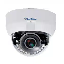
The Target Vandal Proof IP Dome is an outdoor camera designed with
IK10 vandal resistance and IP67 ingress protection. The camera is
equipped with an automatic IR-cut filter and IR LEDs for day and night
surveillance. With the super low lux CMOS image sensor, the camera is
capable of providing a color live view in near darkness. Adjustable in 3 axis
(pan, tilt and rotate), it offers an entry-level surveillance solution with all the
essential features and excellent image quality.
Model No. Specifications Description
GV-EVD2100
2 MP H.264,
WDR, Super Low
Lux
GV-EVD3100
P-Iris,
f:3 ~ 9 mm, F/1.7,
1/2.8”
ø 14 mm lens
mount
3 MP H.264,
WDR Pro, Super
Low Lux
GV-EVD5100
Varifocal
lens
P-Iris,
f:3 ~ 9 mm, F/1.7,
1/2.7”
ø 14 mm lens
mount
5 MP H.264,
WDR, Low Lux
80
5.1 Packing List
Target Vandal Proof IP Dome
Torx Wrench
Screw x 4
Screw Anchor x 4
TV-Out Wire
Audio Wires x 2
Installation sticker
RJ-45 Connector
Conduit Converter
Waterproof Rubber Sets
(for RJ-45 Cat.5 and 12V
DC / for RJ-45 Cat.6)
Cat.6
(Ø 6 mm)
Cat.5
(Ø 5 mm)

Target Vandal Proof IP Dome
81
5
Big Concave hexagon Wrench
Small Concave hexagon
Wrench
Silica Gel Bag Sticker (for Silica Gel Bag)
Ruler Download Guide
Warranty Card
82
5.2 Overview
1 2 3 4 5
6
13 12
10
7
8
9
14
11
Figure 5-1
Target Vandal Proof IP Dome
83
5
No. Name Description
1 LED Indicators
The power LED (top) turns on (green) when
the power is on and turns off when there is
no power supply. The status LED (bottom)
turns on (green) when the system operates
normally and turns off when system error
occurs.
2 Audio Out Connects to a speaker for audio output.
3 Audio In Connects to a microphone for audio input.
4 LAN / PoE Connects to a 10/100 Ethernet or PoE.
5 DC 12V Connects to power.
6 Default Button
Resets the camera to factory default. For
details, see 3.5 Loading Factory Default.
7 Rotational Screw Loosens to rotate the camera.
8 Cable Gland Waterproofs the Ethernet cable.
9 Tilt Screw Loosens the screw to tilt the camera.
10 TV-Out
Provides video input (D1 resolution) for a
monitor.
11 Silica Gel Bag Absorbs moisture in the camera body.
12 Zoom Screw Adjusts the zoom of the camera.
13 Focus Screw Adjusts the focus of the camera.
14 Conduit Connector Waterproofs the audio wires.
84
5.3 Installation
The Target Vandal Proof IP Dome is designed for outdoors. With the
standard package, you can install the camera on the ceiling.
Note: You can also install the camera to ceilings, wall corners (concave
or convex), and poles using optional mounting kits.
For details on these installations, see GV-Mount Accessories Installation
Guide.
1. Remove the housing cover with the supplied torx wrench.
Figure 5-2
Target Vandal Proof IP Dome
85
5
2. Remove the back plate with the supplied torx wrench and remove the
safety lock with a Philips screwdriver. Keep the removed screw for
later use.
Safety lock
Figure 5-3
3. Thread an Ethernet cable and/or the adapter wire into the camera.
A. Rotate to remove the indicated cap.
Figure 5-4
86
B. Take out and disintegrate the connector. You should have 3
parts:
21 3
Figure 5-5
C. Thread an Ethernet cable (the end without RJ-45 connector)
and/or the adapter wire from the back panel.
Figure 5-6
D. Thread an Ethernet cable / adapter wire through part 1 of the
connector. According to the below situation, replace the
connector if necessary.
For users of PoE with a Cat.5 Ethernet cable, stay with 1a
connector on the camera body.
For users of PoE with a Cat.6 Ethernet cable, change the
1a connector to the supplied Waterproof rubber set (1b).
Target Vandal Proof IP Dome
87
5
For users of DC 12V, change the 1a connector to the
supplied Waterproof rubber set (1c). Remove the terminal
block from the power adapter and thread the adapter wire
through the rubber.
F
or a
d
ap
t
er w
i
re
For Ethernet cable
For Cat.5 Ethernet
cable (PoE)
For Cat.6 Ethernet
cable (PoE)
1a 1b 1c
Figure 5-7
E. Thread the Ethernet cable and/or the adapter wire through part 2
and 3 of the connector.
Figure 5-8
IMPORTANT: Use the supplied ruler and leave about 14 cm of the
Ethernet cable and 10 cm of the adapter wire between their connectors
on the camera and the cable gland.
F. Re-install the cap (part 3) with the supplied big concave hexagon
wrench. Make sure the cap is installed tightly to waterproof the
camera.
88
4. Thread audio wires (optional) into the camera.
A. Rotate to remove the cap of the conduit connector.
Figure 5-9
B. Take out and disintegrate the connector. You should have 3
parts too.
C. Thread the audio wires from the back panel, remove the plugs
of part 1 and thread through the 3 parts of the connector.
Plug
Figure 5-10
Target Vandal Proof IP Dome
89
5
D. Re-install the cap (part 3) with the supplied small concave
hexagon wrench. Make sure the cap is installed tightly to
waterproof the camera.
Tip: Use a pair of pliers to help you pull the wires through the
camera.
IMPORTANT:
1. Use the supplied ruler and leave about 10 cm of the audio
wires between their connectors on the camera and the cable
gland.
2. The plugs are used to prevent water from entering the camera
housing. Keep the unused holes plugged and save the
removed plugs for future use.
5. Connect the wires to the camera.
A. Install the terminal block to the power adapter. See 3.4
Connecting the camera.
B. Install the supplied RJ-45 connector to the Ethernet cable.
C. Plug all the connectors to the camera panel.
Tip: Unscrew the indicated screws and lift the camera to help you
connect the wires.
90
6. Sort out the wires at the back. You can have the wires come out from
both positions A and B, or from C.
A
B
C
Figure 5-11
7. Secure the back plate to the ceiling.
A. Paste the sticker to the ceiling. The arrow on the sticker indicates
the direction that the camera faces.
Figure 5-12
B. Drill 4 holes for screws. The recommended ones are indicated as
‘1’.
C. Insert the screw anchors to the 4 holes.
Target Vandal Proof IP Dome
91
5
D. Drill A & B holes or only C hole for sorting out the wires
according to Figure 5-11.
E. Secure the back plate to the ceiling with the supplied screws.
F. To optionally install a pipe, use one of the two methods
illustrated below depending on the type of the back plate that
comes with your camera:
If your plate comes with two knobs (as in Figure 5-13),
install the supplied conduit converter, with the PG21 conduit
connector and a self-prepared 1/2" conduit pipe, to the back
plate.
Conduit
Converter
Plastic PG21 Conduit
Connector
Conduit
Pipe
Figure 5-13
If your plate comes without knobs, install the supplied
conduit connector kit and a self-prepared 1/2" conduit pipe
to the camera after all the wires are threaded.
Conduit pipe
Conduit converter
Plastic PG21
conduit connector
Figure 5-14
92
Note: When installed with a pipe, it is required to supply power through a
PoE adapter, because the power adapter wire does not fit in a 1/2” pipe.
You will have to purchase your own PG21 conduit connector if you want
to use 3/4” or 1” pipe.
A metal PG21 conduit connector can be
purchased upon request, which can be connected to a 3/4” pipe.
8. Secure the camera to the ceiling.
A. Secure the safety lock to the camera with the screw you
removed from the back plate in step 2.
Safety lock
Figure 5-15
B. Thread all the wires into the ceiling and connect them.
C. Secure the camera with the torx wrench.
Figure 5-16
Target Vandal Proof IP Dome
93
5
9. Access the live view. See 6.2 Accessing the Live View.
Note: The TV-out function can be used to access the live view. For
details, see Note for TV-out Function at the beginning of the quick start
guide.
10. Adjust the camera’s angle, focus and zoom of the camera.
Pan Adjustment
Tilt Adjustment
Rotational Adjustment
Figure 5-17
94
11. Replace the silica gel bag, press all the wires and cables into the
notch and secure the camera cover with the torx wrench.
Figure 5-18
Target Vandal Proof IP Dome
95
5
5.4 Connecting the Camera
There are two ways to supply power to the camera:
Use a Power over Ethernet (PoE) adapter to connect the camera to the
network, and the power will be provided at the same time.
Plug the power adapter to the terminal block by inserting the striped
wire to the right pin (-) and the black wire to the left pin (+).
Figure 5-19
96
5.5 Loading Factory Default
5.5.1 Using the Web Interface
You can restore factory default settings through the Web interface. For
details, refer to 1.5.1 Using the Web Interface.
5.5.2 Directly on the Camera
Press and hold the default button for about 8 seconds. Release the default
button when the status LED blinks. For details, see 1.5.2 Directly on the
Camera.
Status LED
Default
Figure 5-20

Chapter 6 Accessing the Camera
6.1 System Requirement
To access the GV-IP Camera through the Web browser, ensure your PC
connects to the network properly and meets this system requirement:
r
. For details, see Appendix A in GV-IPCAM Firmware Manual.
• Microsoft Internet Explorer 8.0 or late
Note: For the users of Internet Explorer 8, additional settings are
required
97

6.2 Accessing the Live View
When the camera is connected to a network with a DHCP server, it will be
automatically assigned with a dynamic IP address. See 6.2.1 Checking the
ress.
IP Address for more detail.
Dynamic IP Address to look up this IP add
However, if you do not have a DHCP server on your network, access the
y its default IP address 192.168.0.10 and see 6.2.2 Configuring camera b
the
98
Accessing the Camera 6
6.2.1 Checking the Dynamic IP Address
mera.
2. The default Administrator and Guest accounts are no longer
supported by GV-IPCam H.265 series firmware V1.14 or later.
When logging in for the first time, you need to set up a login
username and password for the camera. See Creating GV-IP
Camera’s Login Credentials at the beginning of the quick start
guide.
Follow the steps below to look up the IP address and access the Web
interface.
Note:
1. The computer you use to configure the IP address must be under
the same LAN with your ca
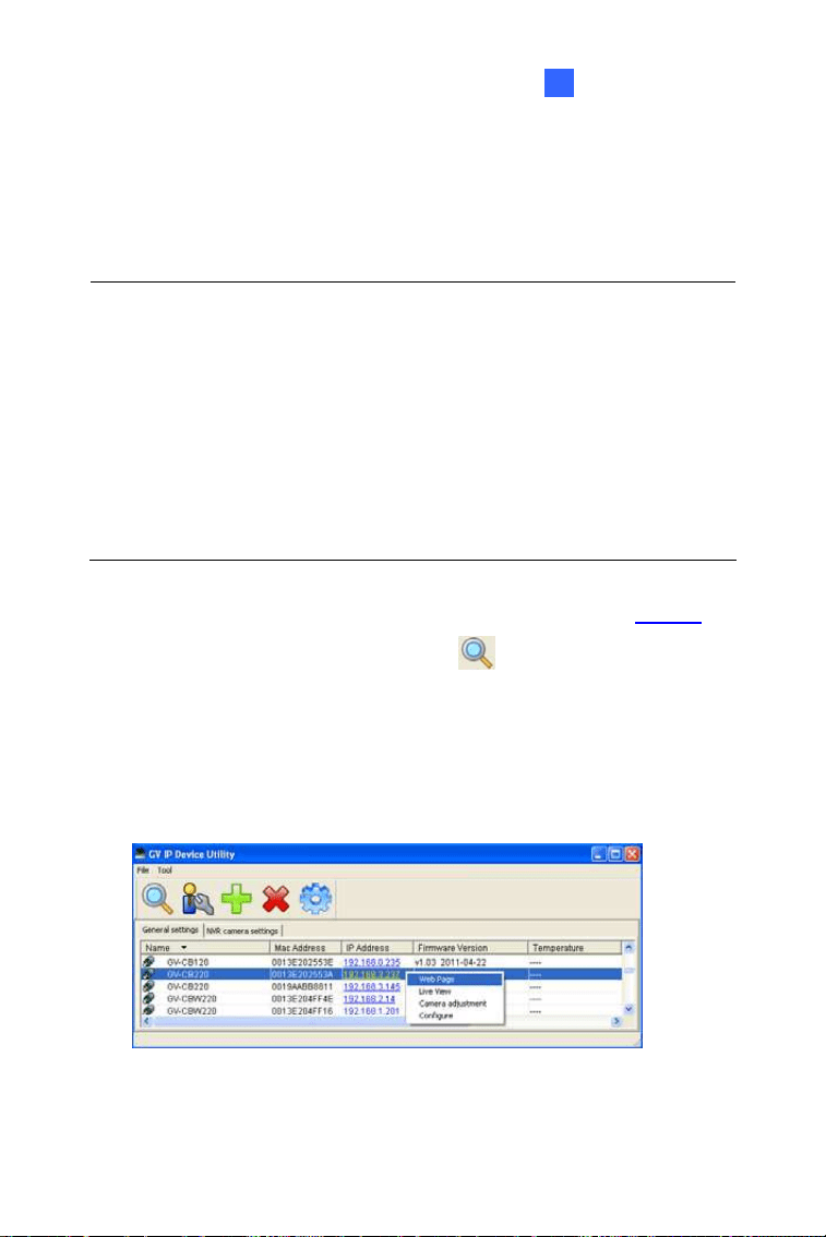
1. Install the GV-IP Device Utility program from the company
website
2. On the GV-IP Utility window, click the
button to search for the IP
devices connected in the same LAN. Click the Name or Mac Address
column to sort.
3. Find the camera with its Mac Address, click on its IP address and
select Web Page.
Figure 6-1
99
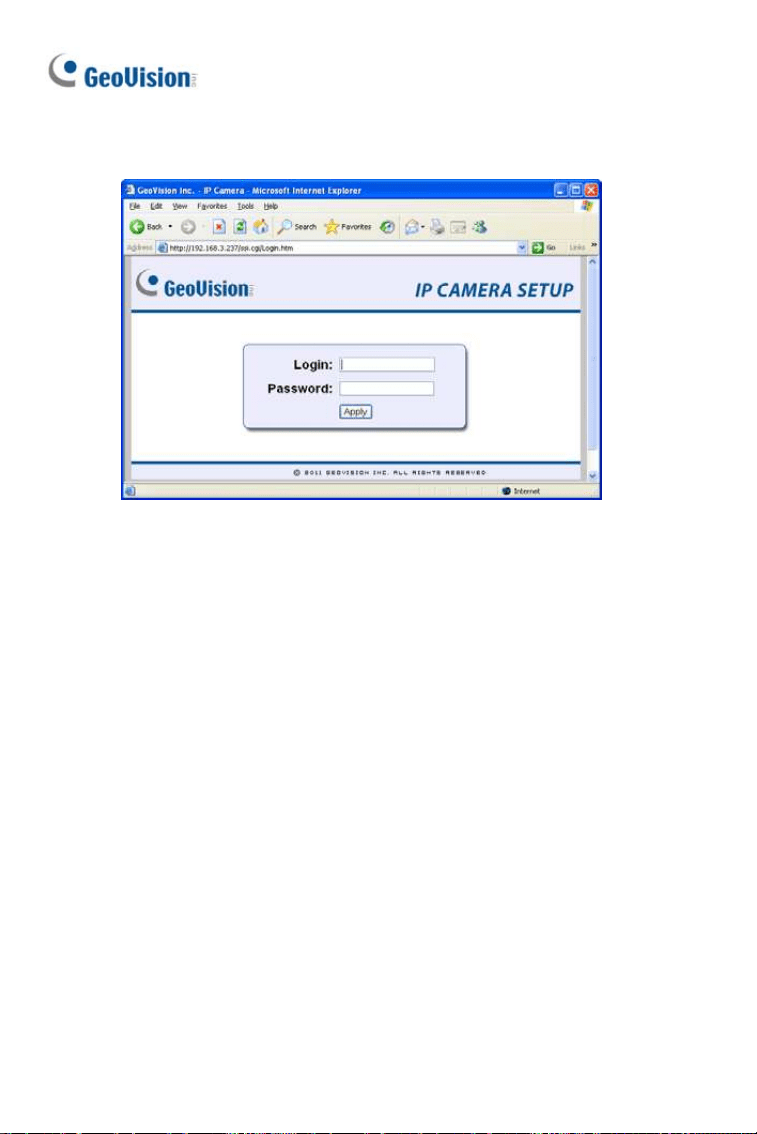
4. The login page appears.
Figure 6-2
5. Type the default ID and password admin and click Apply to log in.
100
Accessing the Camera 6
6.2.2 Configuring the IP Address
Follow the steps below to configure the IP address.
1. Open your Web browser, and type the default IP address
http://192.168.0.10
.
2. In both Login and Password fields, type the default value admin. Click
Apply.
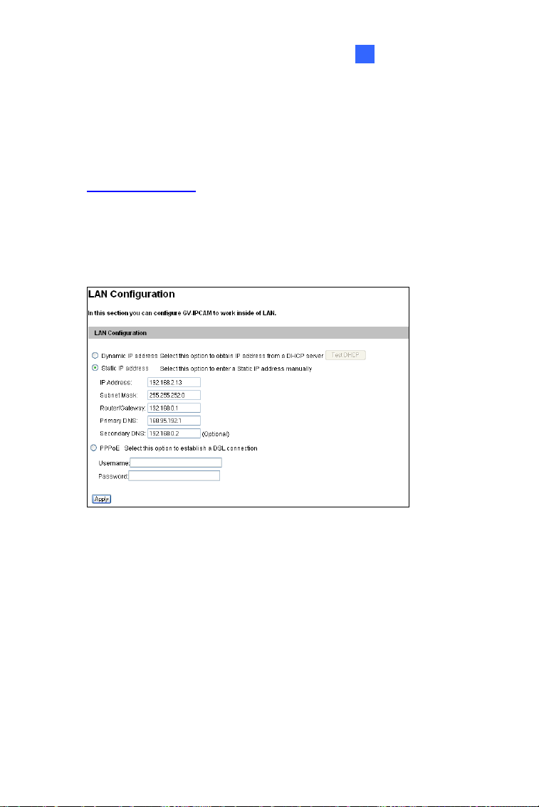
3. In the left menu, select Network and then LAN to begin the network
settings.
Figure 6-3
4. Select Static IP address, Dynamic IP address or PPPoE and type
the required network information.
5. Click Apply. The camera is now accessible by entering the assigned
IP address on the Web browser.
6. To enable the updating of images in Microsoft Internet Explorer, you
must set your browser to allow ActiveX Controls and perform a one-
time installation of GeoVision’s ActiveX component onto your
computer.
101

IMPORTANT:
1. If or is enabled, you need to
erver
ra is installed in the LAN, use the
2.1 Checking the Dynamic IP Address. If your camera
mera’s changing IP address first. For details, see
LAN Configuration and Advanced TCP/IP sections,
Administrator Mode Chapter in the GV-IPCAM Firmware
Manual.
2. If Dynamic IP Address or PPPoE is enabled and you cannot
access the camera, you may have to reset the camera to its
factory default and then perform the network settings again.
To restore factory settings, see 1.5 Loading Factory Default.
Dynamic IP Address PPPoE
know which IP address the camera will get from DHCP s
or ISP to log in. If your came
GV-IP Device Utility to look up its current dynamic IP address.
See 6.
uses a public dynamic IP address via PPPoE, use the
dynamic DNS Service to obtain a domain name that is linked
to the ca
102
Accessing the Camera 6
6.3 Adjusting Image Clarity
Y e image clarity using the GV-IP Device Utility. Make sure
l the
ou can adjust th
that you have connected your GV-IPCAM to the network and instal
GV-IP Device Utility program under the same LAN.
Note: This feature only applies to the cameras that allow manual focus
adjustment.
1. Make sure you have installed the GV-IP Device Utility progr
the compan
am from
y
wevbsite
2. On the GV-IP Utility window, click the
button to search for th
devices connected in the same LAN. Click the IP Address of th
camera you desire. A drop-down list appears.
e IP
e
Focus Value. The Login dialog box appears.
Type the user name and password of the camera selected. The
default is admin for both user name and password. This window
appears.
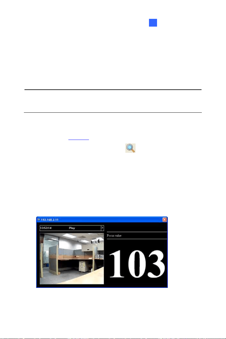
3. Select
4.
Figure 6-4
103

5. For IK10+ models (GV-VD120D / 121D / 220D / 221D / 320D / 321D /
. Adjust the Zoom Screw and the Focus Screw of the camera slowly
until the focus value reaches the maximum.
1500 / 2400 / 3400 / 1530 / 2430 / 2530 / 3430 / 4711 / 5711), hold
the supplied Focus Adjustment Cap over the camera view. For details,
see 6.3.1 Using Focus Adjustment Cap.
6
104

Accessing the Camera 6
Note:
1. For locations of adjustment screws and rings in each model,
2. Do not over tighten the screws. The screws only need to be
as tight as your fingers can get them to be. Do not bother
using any tool to get them tighter. Doing so can damage the
structure of lens.
3. The maximum focus value may vary when the environment
changes.
see Locations of Adjustment Screws, section, Getting Started
Chapter, GV-IPCAM Firmware Manual on the Download
Guide.
105
6.3.1 Using Focus Adjustment Cap
T wo types of Focus Adjustment Caps for GV-VD120D / 121D /
/
ment Cap Type I:
here are t
220D / 221D / 320D / 321D / 1500 / 2400 / 3400 / 1530 / 2430 / 2530
3430 / 4711 / 5711.
Focus Adjust
Figure 6-5
nt Cap
eep
it close to the lens and slightly
image.
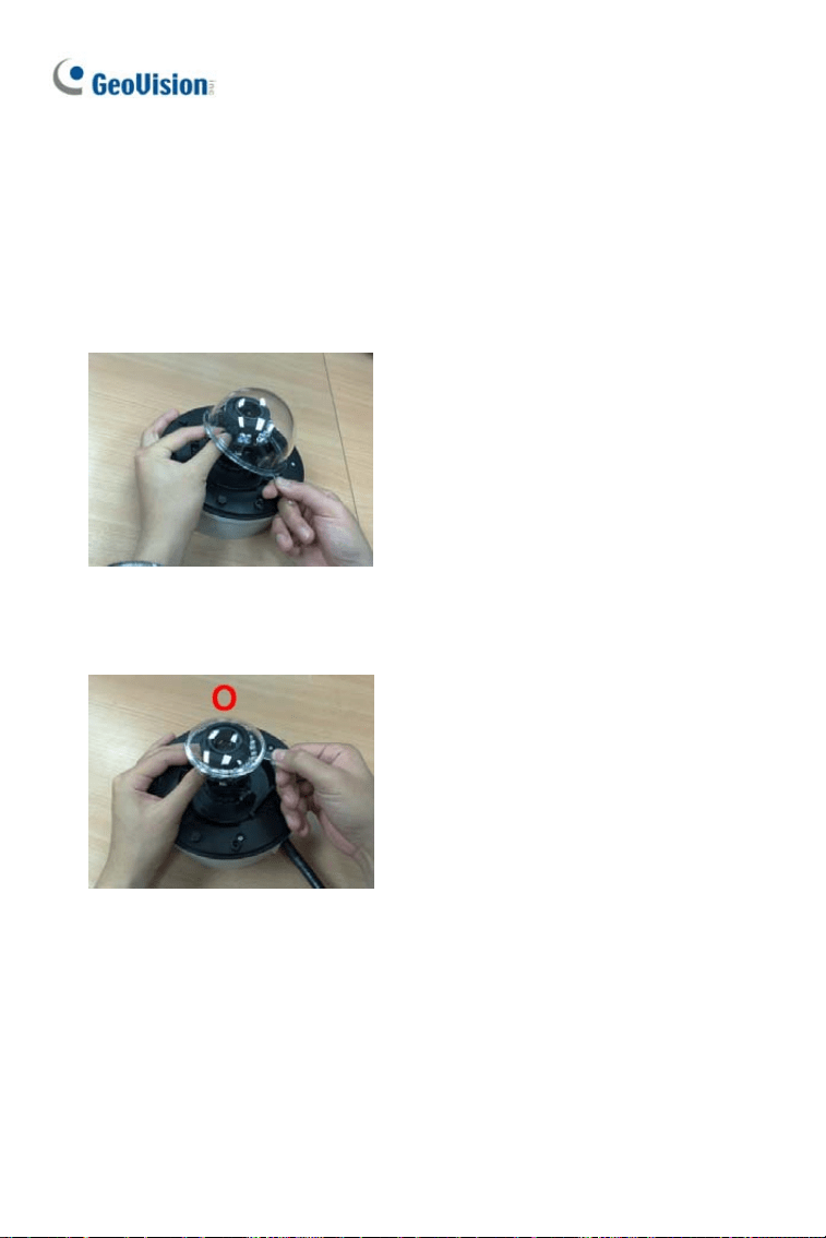
Focus Adjustment Cap Type II:
Hold the Focus Adjustme
on top of the camera view, k
tilt to one side to adjust the
Figure 6-6
Hold the Focus Adjustment Cap
on top of the camera view and
keep it close to the camera.
106
Accessing the Camera
107
6
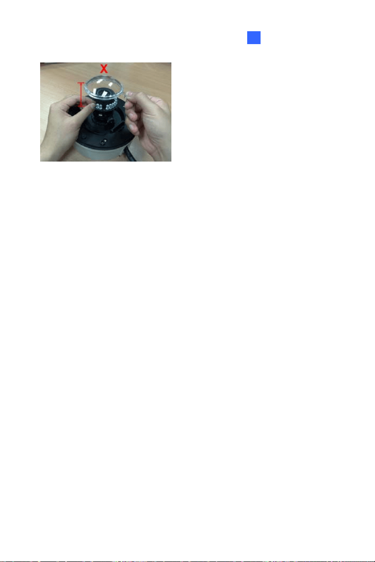
Figure 6-7
leave a distance between
Do not
the Focus Adjustment Cap and
the camera.
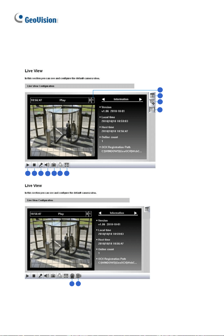
Chapter 7 The Web Interface
1 2 3
4
5 6 7
8
9
10
11
12
13
Figure 7-1
108

Th e W eb I nter fa ce
7
No.
Name Function
1 Play Plays live video.
2 Stop Stops playing video.
3 Microphone
Broadcasts to the surveillance site from a remote
PC. Note this function is not available for Ultra
Bullet Camera and Target Series. For Cube
Camera and Advanced Cube Camera, click the
Push to talk button (from the pop-up menu) for the
camera to switch between audio transmission and
reception, where only one party can speak at a
time.
4 Speaker
Transfers sounds of the surveillance site to a
remote PC. Note this function is not available for,
Mini Fixed Rugged Dome, Ultra Bullet Camera,
Target Bullet Camera, and Target Mini Fixed
Rugged Dome.
5 Snapshot Takes a snapshot of live video.
6 File Save Records live video to the local computer.
7 Full Screen
Switches to full screen view. Right-click the image
to see additional options.
8 Control Panel
Displays the camera information, video settings,
audio data rate, I/O device status, images captured
upon alarm, and GPS location of the camera. Also
allows you to adjust image quality and install the
program from the hard drive.
9
Show System
Menu
Brings up these functions: Alarm Notify, Video and
Audio Configuration, Remote Config, Show
Camera Name and Image Enhance.
109
110
No. Name Function
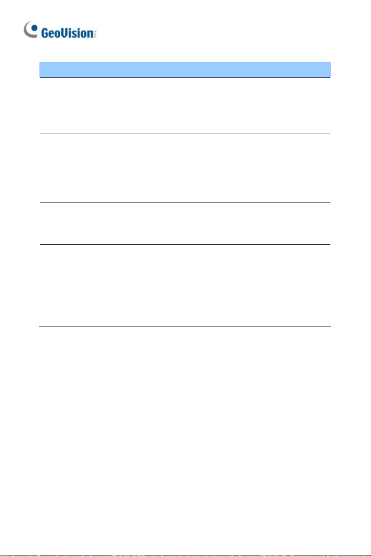
10
rol
ontrol Panel or the Visual PTZ.
y PTZ Camera
only partially supported by
PTZ Cont
Panel
Enables the PTZ C
Note this function is supported b
and PT Camera, and
GV-IP Cameras with motorized varifocal lens.
11 I/O Control
Enables the I/O Control Panel and Visual
Automation. Note this function is not available in
Mini Fixed Dome, Mini Fixed Rugged Dome,
Cube Camera, Advanced Cube Camera and
Target Series.
12 LED Control
Click to turn the Alarm LED on and/or adjust the
brightness sensitivity. Note this function is only
available for Advanced Cube Camera.
13
Alarm
ker section, Administrator Mode
anual on the
Speaker
Click to sound the alarm and/or adjust its volume.
To sound the alarm upon motion or tampering
events, see Spea
Chapter, GV-IPCAM Firmware M
Download Guide. Note this function is only
available for Advanced Cube Camera.

Upgra ding Syst em Fir m w are
8
Chapter 8
r re
GeoVision periodically The new
firmware can be simply
fa ce U
Before you start
z If you use the IP
de
z Stop monitoring
z Stop all remote
z he firmwa
d.
WARNING: The inter auses
not only update failures but also damages to the camera. In this case,
please contact your sales representative and send your device back to
GeoVision for repair.
Upgrading System
Fi mwa
releases updated firmware on the website.
loaded into the GV-IPCAM by using the Web
tility. inter ce or IP Devi
Device Utility for firmware upgrade, the computer
firmware must be under the same network of theused to upgra
camera.
of the camera.
connections, such as GV-VMS.
re is being updated, the power supply must not be
ruption of power supply during updating c
While t
interrupte
z Do not turn the power off within 10 minutes after the firmware is
updated.
111
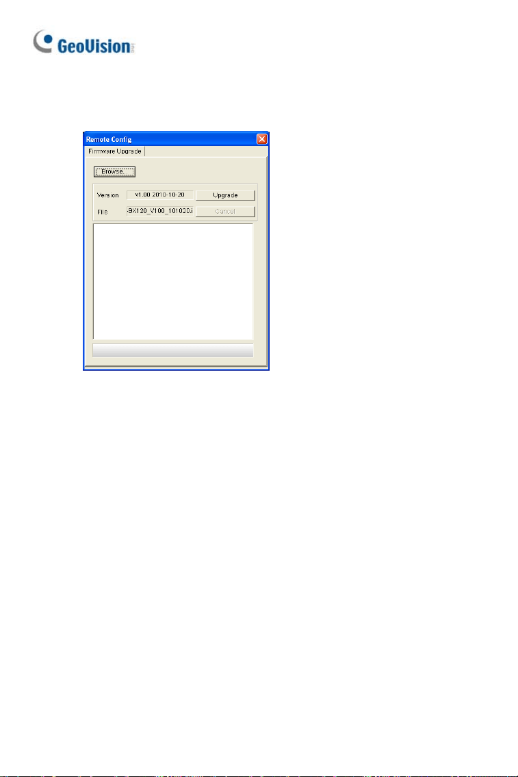
1. In the Live View window, click the Show System Menu button and
select Remote Config. This dialog box appears.
Figure 8-1
2. Click the Browse button to locate the firmware file (.img) saved at
your local computer.
3. Click the Upgrade button to start the upgrade.
112