SUPERSNAP® BODY REPAIR KIT
MODEL No: RE83/10.V2
Thank you for purchasing a Sealey product. Manufactured to a high standard this product will, if used according to these
instructions and properly maintained, give you years of trouble free performance.
1. SAFETY INSTRUCTIONS
2. CONTENTS
IMPORTANT: PLEASE READ THESE INSTRUCTIONS CAREFULLY. NOTE THE SAFE OPERATIONAL REQUIREMENTS, WARNINGS & CAUTIONS. USE
THE PRODUCT CORRECTLY AND WITH CARE FOR THE PURPOSE FOR WHICH IT IS INTENDED. FAILURE TO DO SO MAY CAUSE DAMAGE AND/OR
PERSONAL INJURY AND WILL INVALIDATE THE WARRANTY. PLEASE KEEP INSTRUCTIONS SAFE FOR FUTURE USE.
WARNING! Ensure Health & Safety, local authority and general workshop practice regulations are adhered to when using this equipment.
9 Familiarise yourself with product application and limitations, as well as the specific hazards peculiar to the repair kit.
WARNING! No part of this unit or any accessory relating to the repair kit is designed for lifting loads. It is intended only as a
pushing device and must be used as such, with care.
WARNING! Disconnect the ram from the hydraulic pump before servicing or performing any maintenance on the unit.
9 Maintain kit in good order. Replace/repair with genuine parts only. Unauthorised parts may be dangerous and will invalidate the warranty.
9 Use qualified person to lubricate/maintain the hydraulic pump. DO NOT use brake fluid to top up hydraulic unit. Use Sealey hydraulic oil only.
9 Keep the repair kit clean for best and safest performance.
WARNING! Ensure you know how much load you are pushing. Never exceed the maximum pushing capacity.
9 Use only with the supplied Sealey hydraulic pump and accessories. Wrong equipment may damage unit and invalidate your warranty.
9 The kit accessories may be used with other popular makes of kit.
9 We recommend the use of BS approved safety impact goggles and heavy duty gloves when working with this kit. Both are available from your
authorised Sealey dealer.
9 Ensure there is positive engagement of repair kit accessories to the vehicle body before pushing.
9 Maintain correct balance and footing. Ensure the floor is not slippery and wear non-slip shoes.
9 If working on an ‘off centre’ load, pump with care. If you feel undue resistance, stop and re-adjust the set-up.
WARNING! Keep your hands, body and clothing away from the repair kit and accessories when in use. Take any
necessary precautions to protect your personal safety whilst using the repair kit.
9 Ensure the hydraulic hose is not bent or kinked but laid out correctly. Avoid damage to the hose (e.g. crushing/cutting).
9 Keep non-essential persons away from the operating area. Be aware of the locations of other persons assisting you.
9 When releasing tension from the load be sure to undo the hydraulic valve VERY slowly.
8 DO NOT operate the repair kit if any parts are damaged or missing as this may cause failure and/or personal injury.
WARNING! DO NOT use repair kit as a lifting device of any type. DO NOT use for any purpose other than for which it is designed.
8 DO NOT overextend the ram as the plunger may be forced out of the ram end.
8 DO NOT heat accessories as this may weaken them.
▲ DO NOT modify accessories for use with this kit.
9 When not in use, place dust cap in end of hydraulic hose and store the kit in the case, in a safe, dry, childproof location.
Only fully trained and qualified persons should use this equipment. These instructions are not a substitute for user receiving full
supervised training by a qualified person. It is important the user understands the applications, limitations and potential hazards
of the product.
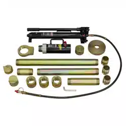
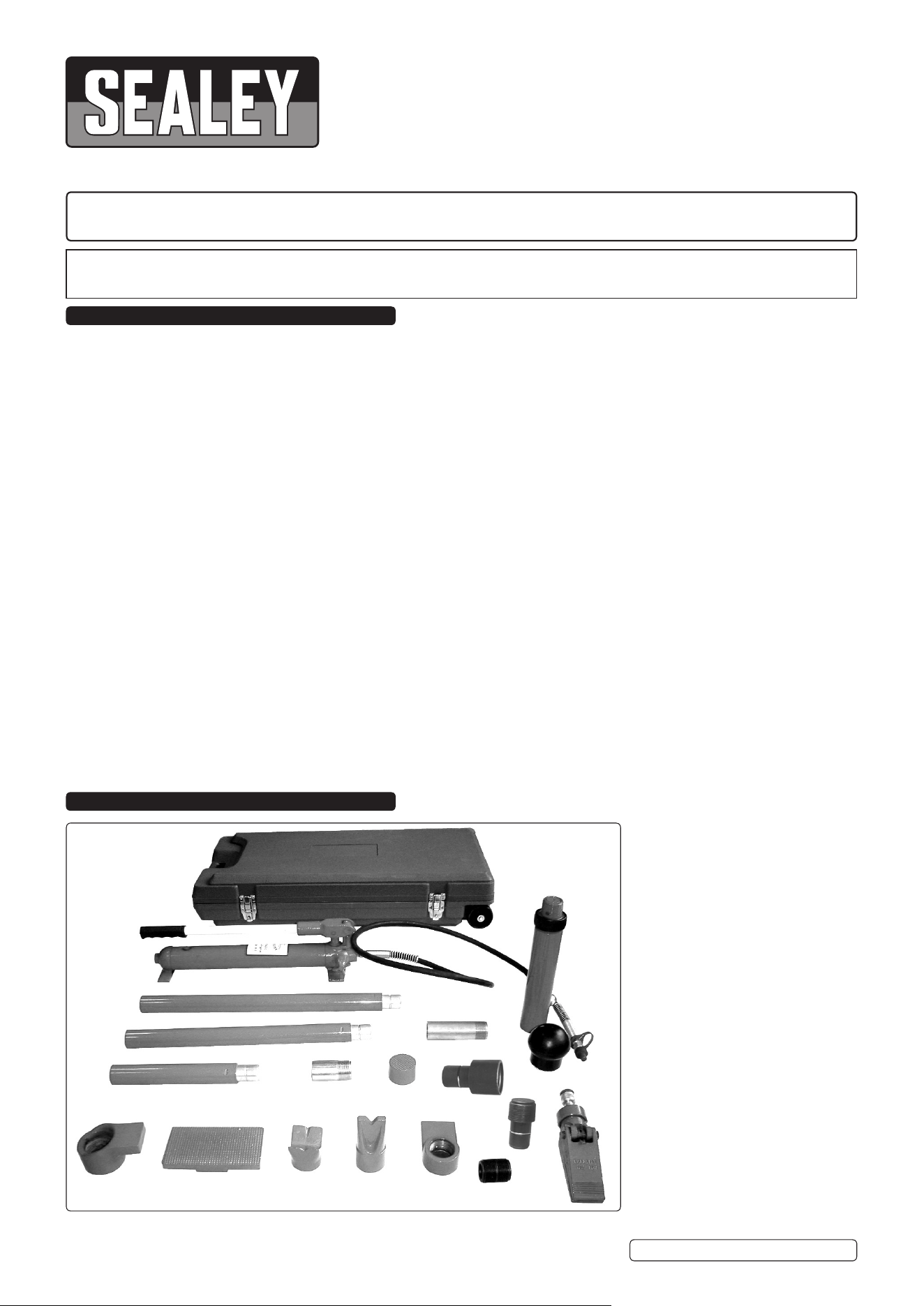
RE83/10.V2
10 ton capacity kit
ITEM PART NO. DESCRIPTION
1 610/1BMC BLOW MOULDED CASE
A2 610/A2 22” SUPERSNAP
®
TUBING
A3 610/A3 19” SUPERSNAP
®
TUBING
A4 610/A4 11” SUPERSNAP
®
TUBING
A5 610/A5 5” TUBE ADAPTOR
A6 610/A6 3” TUBE ADAPTOR
7 610/7 SERRATED SADDLE
8 610/8 MALE CONNECTOR
9 610/9 MALE ADAPTOR
10 610/10 FEMALE ADAPTOR
11 610/11 SPREADER RAM
12 610/12 3-1/4” RUBBER HEAD
13 610/13 FLAT BASE
14 610/14 SPREADER RAM TOE
15 610/15 SPREADER PLUNGER TOE
16 610/16 WEDGE HEAD
17 610/17 90
O
V-BASE
40 610/40 10 TON HYDRAULIC UNIT
41 610/41 RAM
42 610/42 HOSE
1
A2
A3
A4
A5
A6
7
8
9
11
12
13
14
15
16
17
40
41
42
10
RE83-10.V2 Issue 2 (H) 28/05/19
Original Language Version
© Jack Sealey Limited
3. INTRODUCTION
Kit features snap-together pipe work for speed and threaded attachments for strength. Connecting parts are zinc or cad plated for long, rust-
free life. Components are manufactured from high quality steel and finished with red supergloss paint.
IMPORTANT:
Only fully trained and qualified persons should use this equipment. It is very important that the user understands the applications, limitations
and specific hazards of the product.
VEHICLE DAMAGE INTRODUCTION
Before using the repair kit, you must determine the extent of vehicle damage. The technician will check all parts and determine if there is any
broken, torn, crumpled, wrinkled, crushed, twisted or bent metallic parts. Measurements should be taken to see how far out of alignment the
vehicle may be. It is important to determine correct dimensions by referring to the manufacturer’s frame dimension charts and specifications.
Remember, DO NOT commence pushing until you are sure when to stop. Take time to examine and determine damage correctly.
Comprehensive planning will save you time when you are actually using this equipment.
4.1 Hydraulic Ram
(Item 41) For use in large spaces and where a large amount of force is required. Comes with several attachments.
4.2 Extension Bars
(Items A2, A3, A4, A5) Plug into the hydraulic ram in different combinations in order to obtain the required length.
4.3 Serrated Saddle
(Item 7) Typically used on the pushing end in frame repair. Can be attached to either end of the hydraulic ram or extension bars.
4.4 Rubber Head
(Item 12) This is used for popping dents out of doors and/or body panels. Can be attached to either end of the hydraulic ram or
extension bars.
4.5 Flat Base
(Item13) This is used on the stationary side to spread the force of the hydraulic ram. Can be attached to either end of the hydraulic
ram or extension bars.
4.6 Spreader Ram Toe and Spreader Plunger Toe
(Items 14, 15) Typically used for straightening the edges of metal e.g. bumpers. Can be attached to either end of the hydraulic ram or
extension bars.
4.7 90º V Base
(Item 17) This is used to offset the force of the hydraulic ram when there is no straight line between the stationary and damaged sides.
Can be attached to either end of the hydraulic ram or extension bars.
4.8 Spreading Ram
(Item 11) This is used to repair minor dents and damage located in angles and tight spaces. Attaches directly to the pump unit.
4.9 Male Connector
(Item 8) This is used with the extension bars and other attachments that may be connected to the hydraulic ram. Plugs into the female
end of the hydraulic ram.
When positioning the hydraulic ram, it is necessary wherever possible to use a smaller attachment on the side that is to be bent/reshaped.
To further reduce the danger of the stationary side being damaged, place a block of wood or other suitable material (e.g. dense rubber) behind
the base plate, in order to cushion the stationary side and spread the pressure exerted by the hydraulic ram.
4. ATTACHMENTS
5. ASSEMBLY
5.1 Unscrew the end plugs from the hose and hydraulic ram. Retain end caps for use when storing the kit.
5.2 Screw the hose into the hydraulic ram. Ensure the hose is secure but DO NOT overtighten.
5.3 Fit the pump handle to the pump unit - DO NOT overtighten.
To provide maximum versatility a combination of pump accessories may be used.
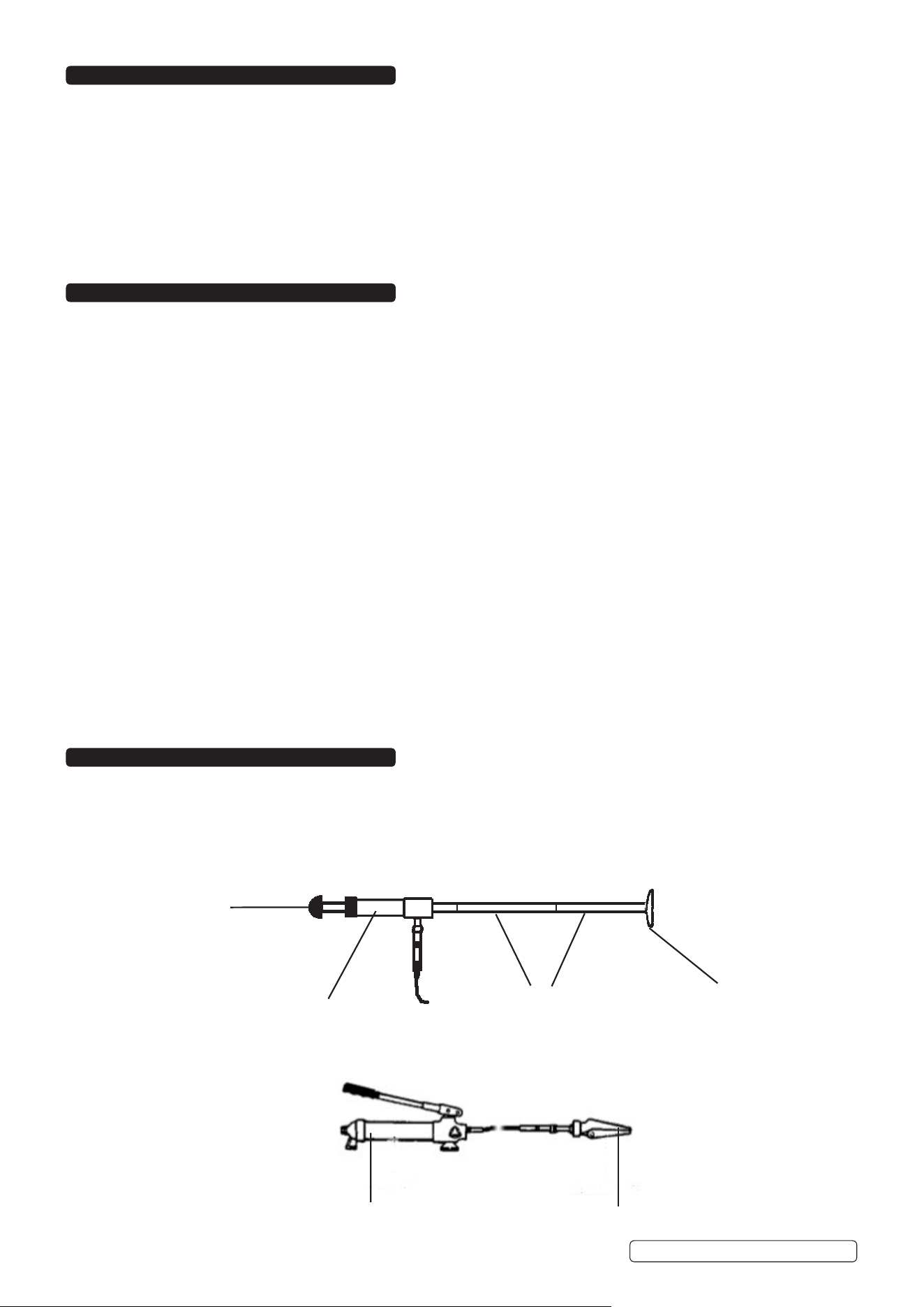
5.4 To use the rubber head, base plate and extension bars with the hydraulic ram, see fig 1.
Base plate
Extension bars
Hydraulic ram
Rubber head
fig 1
5.5 In order to attach the spreader ram, see fig 2.
Spreader ram
Pump unit
fig 2
RE83-10.V2 Issue 2(H) 28/05/19
Original Language Version
© Jack Sealey Limited
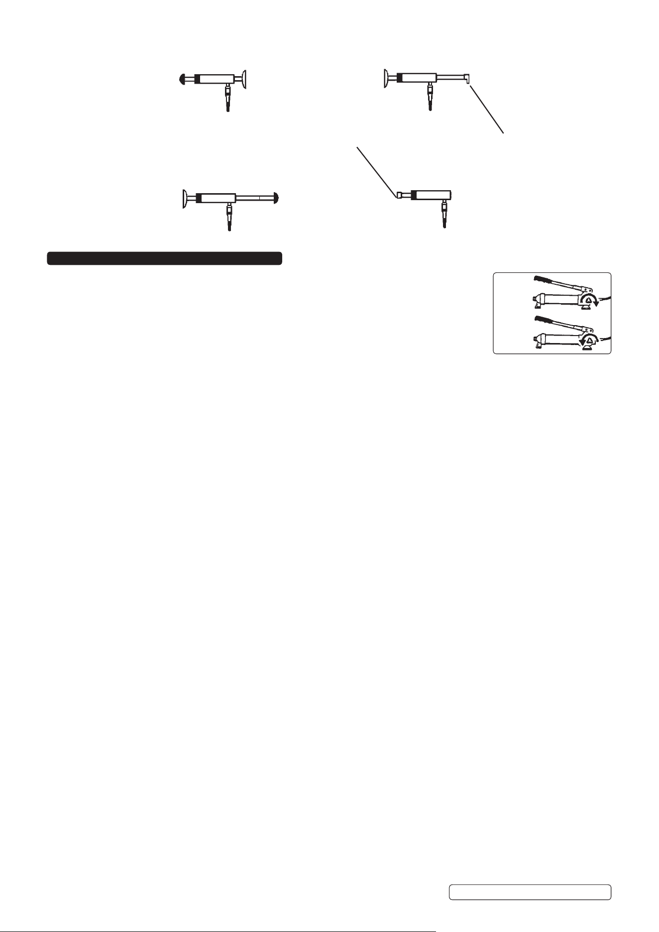
5.6 Four other common combinations are illustrated below:
V BaseSerrated saddle
WARNING! Ensure you have read and understood chapter 1 safety instructions.
NOTE: These instructions are intended to provide a guide to the basic operation of the body repair kit
and are in no way intended to replace the advice/instruction of a qualified mechanic/car body repair
specialist. Only fully trained persons should use this equipment.
6.1 The pump may be used in any position from horizontal to vertical. When not horizontal ensure the hose
end of the pump is down.
6.2 To use the pump, close valve (fig 3.A) by turning the knob clockwise and pump the the handle up and
down to apply the load.
6.3 To release pump pressure, turn knob anti-clockwise (B).
6.4 REPAIRING FRAME DAMAGE
6.4.1 Determine the direction in which the frame needs to be bent.
6.4.2 Carefully remove any obstructions and items that may be damaged in the bending process.
6.4.3 Attach the base plate to the stationary side of the hydraulic ram.
6.4.4 Attach the appropriate attachment/combination of attachments to the pushing end of the hydraulic ram.
6.4.5 Position the assembled kit appropriately i.e. with the base plate resting against a frame member opposite the damaged area and in
line with the direction in which the damaged area needs to be pushed.
6.4.6 Slowly extend the ram, being sure to direct the moving end of the ram toward the area in need of repair until contact is made.
6.4.7 Move as far away as possible and continue to slowly operate the pump, applying pressure until the desired bend has been made.
6.4.8 When operation is complete, slowly turn the release valve anti-clockwise. Remove the hydraulic ram.
6.5 REPAIRING BODY DAMAGE
6.5.1 Determine the direction in which the body panel needs to be moved.
6.5.2 Carefully remove any obstructions and items that may be damaged in the bending process.
6.5.3 Attach the base plate to the stationary side of the hydraulic ram.
6.5.4 Attach the appropriate attachment/combination of attachments to the pushing end of the hydraulic ram.
6.5.5 Position the assembled kit appropriately i.e. with the base plate resting against a frame/robust body part opposite the damaged area
and in line with the direction in which the damaged area needs to be pushed. Be sure that the stationary frame/body part is stronger
than the area to be bent (a block of wood or rubber may be used to protect the stationary part).
6.5.6 Slowly extend the ram, being sure to direct the moving end toward the area in need of repair until contact is made.
6.5.7 Move as far away as possible and continue to slowly operate the pump, applying pressure until the desired bend has been made.
6.5.8 When operation is complete, slowly turn the release valve anti-clockwise. Remove the hydraulic ram.
6.6 USING THE SPREADER RAM
6.6.1 Determine the direction in which the body panel needs to be moved.
6.6.2 Carefully remove any obstructions and items that may be damaged in the bending process.
6.6.3 Place the spreader ram such that the hinged arm is resting against the part to be moved and the stationary arm is resting against a
strong fixed base. Holding the spreader ram in position, operate the pump until contact is made.
6.6.4 Move as far away as possible and continue to slowly operate the pump, applying pressure until the desired bend has been made.
6.6.5 When operation is complete, slowly turn the release valve anti-clockwise. Remove the spreader ram.
IMPORTANT: Always store the ram with the piston fully retracted to help prevent corrosion. Rams with signs of rust on the main
piston cannot be replaced under warranty.
Rams with signs of damage to the piston or the cylinder and/or with damaged hydraulic couplings cannot be accepted under
warranty. Due to the severe abuse required to cause damage to the pump piston or arm hinge mechanism, these cannot be
accepted under warranty.
6. INSTRUCTIONS FOR USE
A
fig 3
B
RE83-10.V2 Issue 2(H) 28/05/19
Original Language Version
© Jack Sealey Limited
IMPORTANT: NO RESPONSIBILITY IS ACCEPTED FOR INCORRECT USE OF THE PUMP AND/OR RAM.
Hydraulic products are only repaired by local service agents. We have service/repair agents in all parts of the UK.
DO NOT RETURN PUMP OR RAM TO US. Please telephone us on 01284 757500 to obtain the address and ‘phone number of your local
agent.
If product is under guarantee please contact your dealer.
DE-COMMISSIONING HYDRAULIC PUMP/RAM
Should the pump or ram become completely unserviceable draw off the oil into an approved container and dispose of the product and the oil
according to local regulations.
7. MAINTENANCE
IMPORTANT: Only fully qualified personnel should attempt maintenance or repair to the hydraulic system.
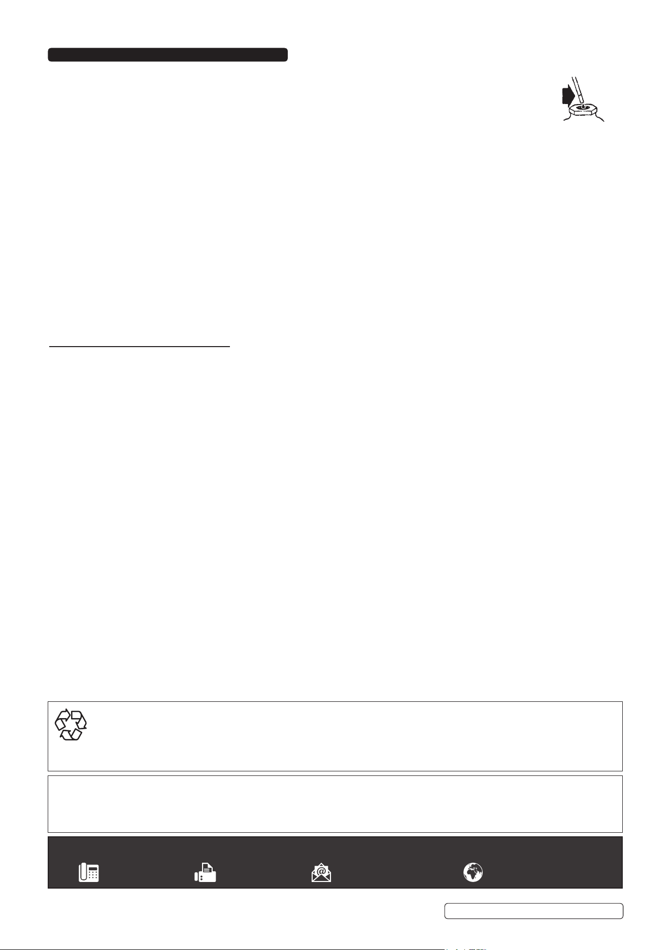
7.1 PUMP OIL LEVEL
Release pressure and disconnect the ram from the pump.
Hold pump in an upright position.
Remove filler plug and add hydraulic oil until it is level with the full mark (fig 4).
WARNING: DO NOT use brake fluid, or any fluid other than hydraulic jack fluid, as this may cause serious damage to the pump/ram
and will invalidate the warranty! Use only Sealey hydraulic oil.
7.2 GENERAL
Before each use check for broken, cracked, bent, or loose parts, or any visible damage to welds, ram, pump, hose and accessories.
If any suspect item is found remove from service and take necessary action to remedy the problem.
Replace/repair with genuine parts only. Unauthorised parts may be dangerous and will invalidate the warranty.
Keep all parts of the kit clean - use only a mild detergent and a damp cloth. DO NOT use solvents.
Note: A small amount of oil around ram seal is normal - a thicker layer of oil may be deposited onto the ram initially, due to the ram
seals bedding in. Hydraulic couplings will weep a small amount of oil, particularly if ram is under pressure when coupling is
released - this is normal.
fig 4
RE83-10.V2 Issue 2(H) 28/05/19
Original Language Version
© Jack Sealey Limited
Sealey Group, Kempson Way, Suffolk Business Park, Bury St Edmunds, Suffolk. IP32 7AR
01284 757500 01284 703534 sales@sealey.co.uk www.sealey.co.uk
ENVIRONMENT PROTECTION
Recycle unwanted materials instead of disposing of them as waste. All tools, accessories and packaging should be sorted, taken to
a recycling centre and disposed of in a manner which is compatible with the environment. When the product becomes completely
unserviceable and requires disposal, drain any fluids (if applicable) into approved containers and dispose of the product and fluids
according to local regulations.
Note: It is our policy to continually improve products and as such we reserve the right to alter data, specifications and component parts without
prior notice.
Important: No Liability is accepted for incorrect use of this product.
Warranty: Guarantee is 12 months from purchase date, proof of which is required for any claim.