
Self Starter
Mulching Mower
Model 569
PRINTED IN U.S.A.
Operator’s Manual
FORM NO.
769-00982.fm
(11/2003)
IMPORTANT: Read safety rules and instructions carefully before operating equipment.
Warning: This unit is equipped with an internal combustion engine and should not be used on or near any unimproved forest-cov-
ered, brush-covered or grass-covered land unless the engine’s exhaust system is equipped with a spark arrester meeting applicable
local or state laws (if any). If a spark arrester is used, it should be maintained in effective working order by the operator. In the State
of California the above is required by law (Section 4442 of the California Public Resources Code). Other states may have similar laws.
Federal laws apply on federal lands. A spark arrester for the muffler is available through your nearest engine authorized service dealer
or contact the service department, P.O. Box 361131 Cleveland, Ohio 44136-0019.
Troy-Bilt LLC, P.O. BOX 361131 CLEVELAND, OHIO 44136-0019
2
TABLE OF CONTENTS
FINDING MODEL NUMBER
This Operator’s Manual is an important part of your new lawn mower. It will help you assemble, prepare and
maintain the unit for best performance. Please read and understand what it says.
Before you start assembling your new equipment, please locate the model plate on the
equipment and copy the information from it in the space provided below. A sample model plate is
also given below. You can locate the model plate by standing at the operating position and
looking down at the rear of the deck. This information will be necessary to use the
manufacturer’s web site and/or help from the Customer Support Department or an authorized
service dealer.
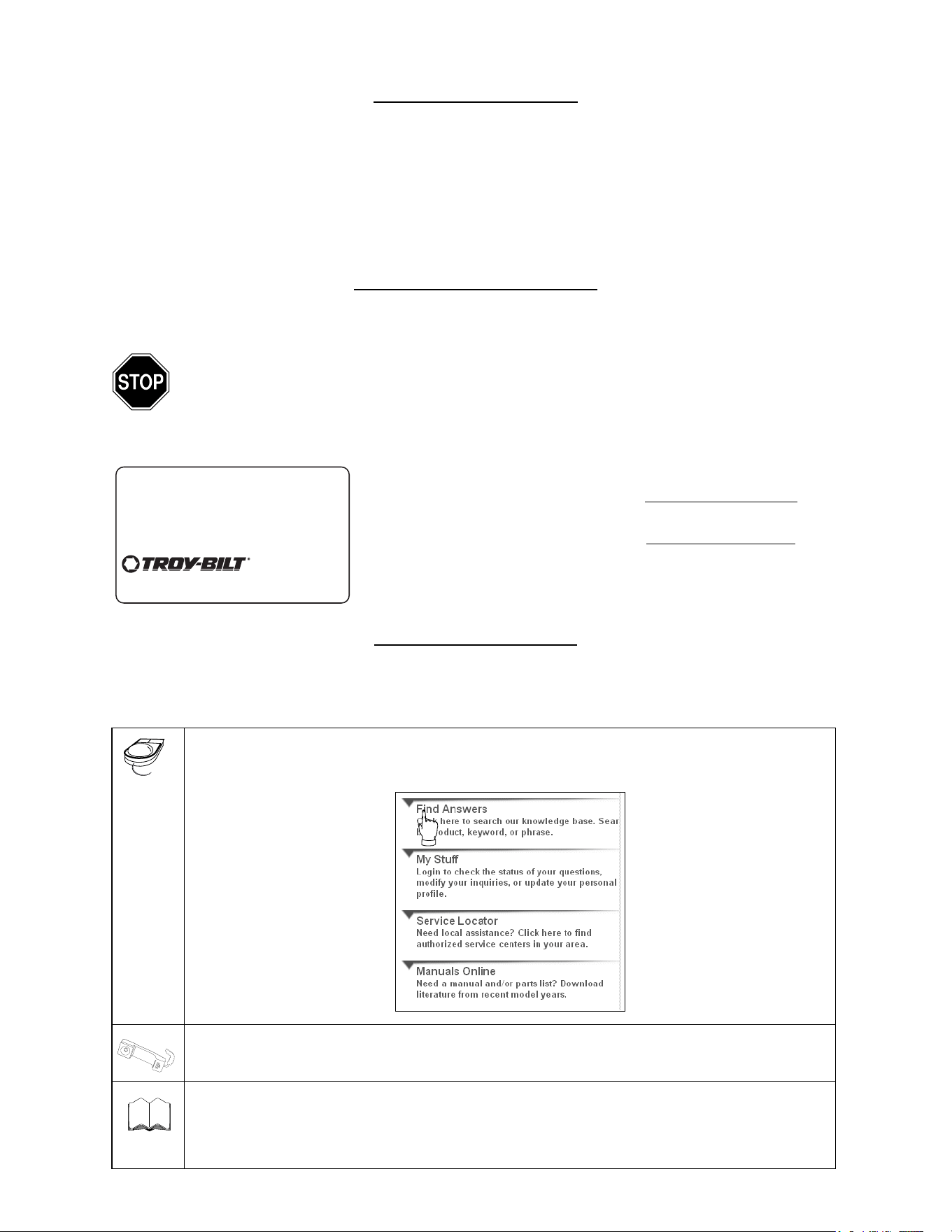
CUSTOMER SUPPORT
Please do NOT return the unit to the retailer from where it was purchased, without first contacting Customer Support.
If you have difficulty assembling this product or have any questions regarding the controls, operation or
maintenance of this unit, you can seek help from the experts. Choose from the options below:
Visit troybilt.com for many useful suggestions. Click on Customer Support button and you will
get the four options reproduced here. Click on the appropriate button and help is immediately
available.
To reach a Customer Support Representative, please call 1-800-520-5520.
The engine manufacturer is responsible for all engine-related issues with regards to
performance, power-rating, specifications, warranty and service. Please refer to the engine
manufacturer’s Owner’s/Operator’s Manual, packed separately with your unit, for more
information.
Content Page
Important Safe Operation Practices 3
Slope Gauge 6
Assembling Your Lawn Mower 7
Know Your Lawn Mower 9
Operating Your Lawn Mower 10
Maintaining Your Lawn Mower 12
Service & Adjustments 14
Troubleshooting 16
Illustrated Parts List 17
Warranty 20
Content Page
Copy the model number here:
Copy the serial number here:
www.troybilt.com
TROY-BILT LLC
P. O. BOX
361131
CLEVELAND, OH 44136
1-800-520-5520
330-558-7220
The answer you are
looking for could be just
a mouse click away!
The answer you are
looking for could be just
a mouse click away!
Engine
Manual

3
SECTION 1: IMPORTANT SAFE OPERATION PRACTICES
General Operation
1. Read this operator’s manual carefully in its entirety
before attempting to assemble this machine. Read,
understand, and follow all instructions on the
machine and in the manual(s) before operation. Be
completely familiar with the controls and the proper
use of this machine before operating it. Keep this
manual in a safe place for future and regular
reference and for ordering replacement parts.
2. This machine is a precision piece of power
equipment, not a plaything. Therefore, exercise
extreme caution at all times. Your unit has been
designed to perform one job: to mow grass. Do not
use it for any other purpose.
3. Never allow children under 14 years old to operate
this machine. Children 14 years old and over
should read and understand the operation
instructions and safety rules in this manual and
should be trained and supervised by a parent. Only
responsible individuals who are familiar with these
safe operation rules should use this machine.
4. Thoroughly inspect the area where equipment is to
be used. Remove all stones, sticks, wire, bones,
toys and other foreign objects which could be
tripped over or picked up and thrown by the blade.
Thrown objects can cause serious personal injury.
Plan your mowing pattern to avoid discharge of
material toward roads, sidewalks, bystanders and
the like. Also, avoid discharging material against a
wall or obstruction which may cause discharged
material to ricochet back toward the operator.
5. To help avoid blade contact or a thrown object
injury, stay in the operator zone behind the handles
and keep bystanders, helpers, children and pets at
least 75 feet from the machine while it is in
operation. Stop machine if anyone enters the area.
6. Always wear safety glasses to protect your eyes
during equipment operation and while performing
an adjustment or repair. Thrown objects which
ricochet can cause serious injury to the eyes.
7. Wear sturdy, rough-soled work shoes and close-
fitting slacks and shirts. Shirts and pants that cover
the arms and legs and steel-toed shoes are
recommended. Never operate this machine in bare
feet, sandals, slippery or light weight (e.g. canvas)
shoes.
8. Do not put hands or feet near rotating parts or
under the cutting deck. Contact with the blade can
amputate hands and feet.
9. A missing or damaged discharge cover can cause
blade contact or thrown object injuries.
10. Many injuries occur as a result of the mower being
pulled over the foot during a fall caused by slipping
or tripping. Do not hold on to the mower if you are
falling; release the blade control bar immediately.
11. Never pull the mower back toward you while you
are walking. If you must back the mower away from
a wall or obstruction first look down and behind to
avoid tripping and then follow these steps:
a. Step back from the mower to fully extend
your arms.
b. Be sure you are well balanced with sure
footing.
c. Pull the mower back slowly, no more than
half way toward you.
d. Repeat these steps as needed.
5. Do not operate the mower while under the influence
of alcohol or drugs.
6. Do not engage the self-propelled mechanism on
units so equipped while starting engine.
7. The blade control bar is a safety device. Never
attempt to bypass its operation. Doing so makes
the safety device inoperative and may result in
personal injury through contact with the rotating
blade. The blade control bar must operate easily in
both directions and automatically return to the
disengaged position when released.
8. Never operate the mower in wet grass. Always be
sure of your footing. A slip and fall can cause
serious personal injury. If you feel you are losing
WARNING: This symbol points out important safety instructions which, if not followed, could endanger
the personal safety and/or property of yourself and others. Read and follow all instructions in this manual
before attempting to operate this machine. Failure to comply with these instructions may result in personal
injury. When you see this symbol—HEED ITS WARNING.
WARNING: Engine exhaust, some of its constituents, and certain vehicle components contain or emit
chemicals known to State of California to cause cancer and birth defects or other reproductive harm.
WARNING: This machine was built to be operated according to the rules for safe operation in this
manual. As with any type of power equipment, carelessness or error on the part of the operator can result in
serious injury. This machine is capable of amputating hands and feet and throwing objects. Failure to
observe the following safety instructions could result in serious injury or death.

4
your footing, release the blade control handle
immediately and the blade will stop rotating within
three seconds.
9. Mow in daylight or good artificial light; walk, not run.
10. Stop the blade when crossing gravel drives,
walkways or roads.
11. If the equipment should start to vibrate abnormally,
stop the engine and check immediately for the
cause. Vibration is generally a warning of trouble.
12. Shut the engine off and wait until the blade comes
to a complete stop before removing the grass
catcher or unclogging the chute. The cutting blade
continues to rotate for a few seconds after the
engine is shut off. Never place any part of the body
in the blade area until you are sure the blade has
stopped rotating.
13. Never operate mower without proper trail shield,
discharge cover, grass catcher, blade control bar or
other safety protective devices in place and
working. Never operate mower with damaged
safety devices. Failure to do so can result in
personal injury.
14. Muffler and engine become hot and can cause a
burn. Do not touch.
15. Only use parts and accessories made by the
original equipment manufacturer (O.E.M). Failure
to do so can result in personal injury.
16. If situations occur which are not covered in this
manual, use care and good judgment. Contact your
dealer for assistance. Call1-800-520-5520 for the
name of your nearest dealer.
Slope Operation
Slopes are a major factor related to slip and fall
accidents which can result in severe injury. Operation
on slopes requires extra caution. If you feel uneasy on a
slope, do not mow it. Before operating this unit on a
slope or hilly area, use the slope gauge on page 6 to
measure slopes. If the slope is greater than 15 degrees,
do not mow it.
Do:
1. Mow across the face of slopes; never up and down.
Exercise caution when changing direction.
2. Watch for holes, ruts, rocks, hidden objects, or
bumps which can cause you to slip or trip. Tall
grass can hide obstacles.
3. Always be sure of your footing. A slip and fall can
cause serious personal injury. If you feel you are
losing your balance, release the blade control
handle immediately, and the blade will stop rotating
within 3 seconds.
Do Not:
1. Do not mow near drop-offs, ditches or
embankments, you could lose your footing or
balance.
2. Do not mow slopes greater than 15 degrees as
shown on the slope gauge.
3. Do not mow on wet grass. Unstable footing could
cause slipping.
Children
Tragic accidents can occur if the operator is not alert to
the presence of children. Children are often attracted to
the mower and the mowing activity. They do not
understand the dangers. Never assume that children
will remain where you last saw them.
1. Keep children out of the mowing area and under
the watchful care of a responsible adult other than
the operator.
2. Be alert and turn mower off if a child enters the
area.
3. Before and while moving backwards, look behind
and down for small children.
4. Use extreme care when approaching blind corners,
doorways, shrubs, trees, or other objects that may
obscure your vision of a child who may run into the
mower.
5. Keep children away from hot or running engines.
They can suffer burns from a hot muffler.
6. Never allow children under 14 years old to operate
a power mower. Children 14 years old and over
should read and understand the operation
instructions and safety rules in this manual and
should be trained and supervised by a parent.
Service
Safe Handling of Gasoline:
1. To avoid personal injury or property damage use
extreme care in handling gasoline. Gasoline is
extremely flammable and the vapors are explosive.
Serious personal injury can occur when gasoline is
spilled on yourself or your clothes which can ignite.
2. Wash your skin and change clothes immediately.
3. Use only an approved gasoline container.
4. Never fill containers inside a vehicle or on a truck or
trailer bed with a plastic liner. Always place
containers on the ground away from your vehicle
before filling.
5. If possible, remove gas-powered equipment from
the truck or trailer and refuel it on the ground. If this
is not possible, then refuel such equipment on a
trailer with a portable container, rather than from a
gasoline dispenser nozzle.
6. Keep the nozzle in contact with the rim of the fuel
tank or container opening at all times until fueling is
complete. Do not use a nozzle lock-open device.
7. Extinguish all cigarettes, cigars, pipes and other
sources of ignition.
8. Never fuel machine indoors because flammable
vapors will accumulate in the area.

5
9. Never remove gas cap or add fuel while the engine
is hot or running. Allow engine to cool at least two
minutes before refueling.
10. Never over fill fuel tank. Fill tank to no more than ½
inch below bottom of filler neck to provide space for
fuel expansion.
11. Replace gasoline cap and tighten securely.
12. If gasoline is spilled, wipe it off the engine and
equipment. Move unit to another area. Wait 5
minutes before starting the engine.
13. Never store the machine or fuel container inside
where there is an open flame, spark or pilot light as
on a water heater, space heater, furnace, clothes
dryer or other gas appliances.
14. To reduce fire hazard, keep mower free of grass,
leaves, or other debris build-up. Clean up oil or fuel
spillage and remove any fuel soaked debris.
15. Allow a mower to cool at least 5 minutes before
storing.
General Service:
1. Never run an engine indoors or in a poorly
ventilated area. Engine exhaust contains carbon
monoxide, an odorless and deadly gas.
2. Before cleaning, repairing, or inspecting, make
certain the blade and all moving parts have
stopped. Disconnect the spark plug wire and
ground against the engine to prevent unintended
starting.
3. Check the blade and engine mounting bolts at
frequent intervals for proper tightness. Also,
visually inspect blade for damage (e.g., bent,
cracked, worn) Replace blade with the original
equipment manufacture’s (O.E.M.) blade only,
listed in this manual. “Use of parts which do not
meet the original equipment specifications may
lead to improper performance and compromise
safety!”
4. Mower blades are sharp and can cut. Wrap the
blade or wear gloves, and use extra caution when
servicing them.
5. Keep all nuts, bolts, and screws tight to be sure the
equipment is in safe working condition.
6. Never tamper with safety devices. Check their
proper operation regularly.
7. After striking a foreign object, stop the engine,
disconnect the spark plug wire and ground against
the engine. Thoroughly inspect the mower for any
damage. Repair the damage before starting and
operating the mower.
8. Never attempt to make a wheel or cutting height
adjustment while the engine is running.
9. Grass catcher components, discharge cover, and
trail shield are subject to wear and damage which
could expose moving parts or allow objects to be
thrown. For safety protection, frequently check
components and replace immediately with original
equipment manufacturer’s (O.E.M.) parts only,
listed in this manual. “Use of parts which do not
meet the original equipment specifications may
lead to improper performance and compromise
safety!”
10. Do not change the engine governor setting or
overspeed the engine. The governor controls the
maximum safe operating speed of the engine.
11. Maintain or replace safety and instruction labels, as
necessary.
12. Observe proper disposal laws and regulations.
Improper disposal of fluids and materials can harm
the environment.
Your Responsibility
• Restrict the use of this power machine to persons who read, understand and follow the warnings and
instructions in this manual and on the machine.
1299 AC
6
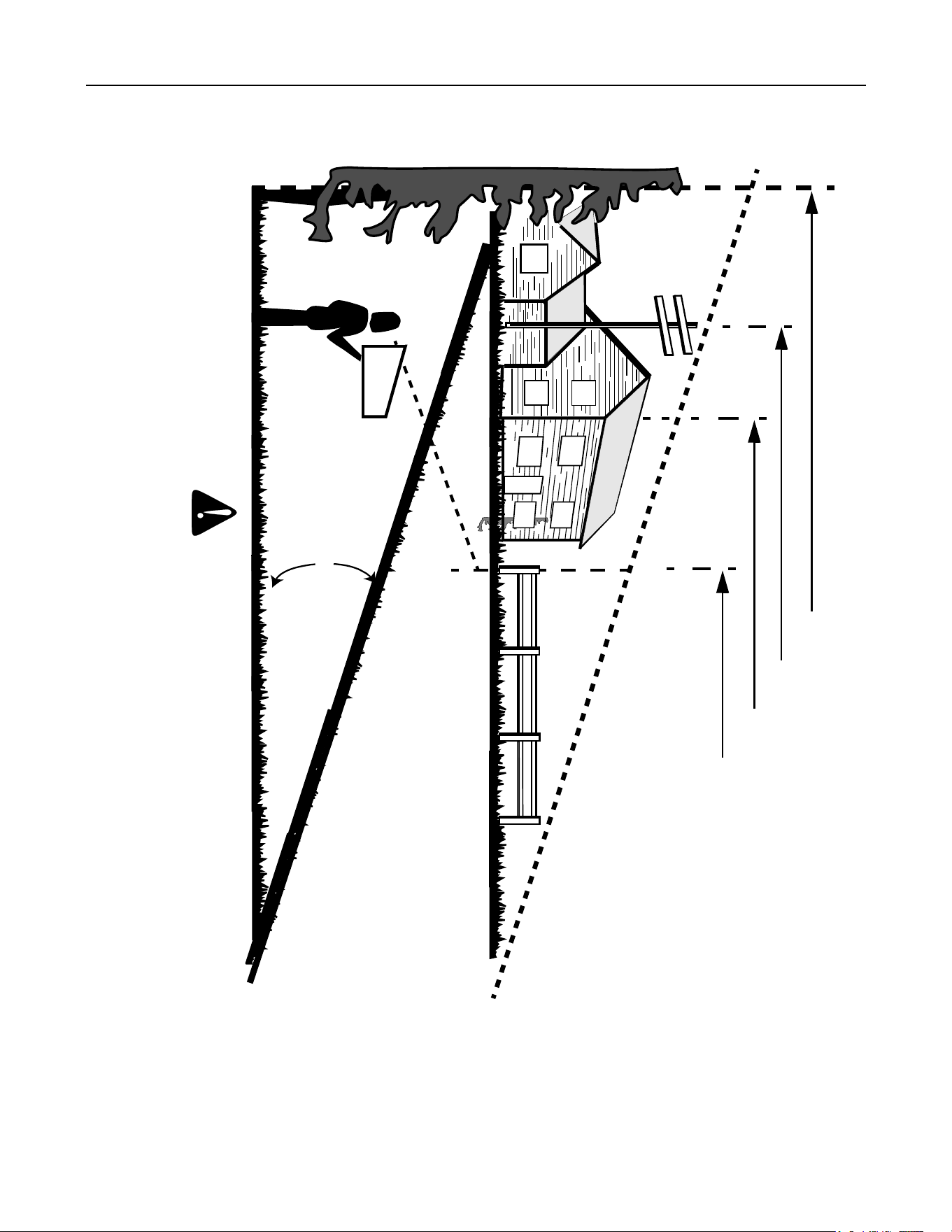
SECTION 2: SLOPE GAUGE
Use this page as a guide to determine slopes where you may not operate safely.
15
o
SIGHT AND HOLD THIS LEVEL WITH A VERTICAL TREE
A POWER POLE
A CORNER OF A BUILDING
OR A FENCE POST
F
O
L
D
ON
D
O
T
T
E
D
L
I
N
E,
R
E
P
R
E
SE
N
T
I
N
G
A
1
5
o
S
L
OP
E
WARNING
Do not mow on inclines with a slope in excess of 15 degrees (a rise of approximately 2-1/2 feet every 10 feet). A riding mower
could overturn and cause serious injury. If operating a walk-behind mower on such a slope, it is extremely difficult to maintain
your footing and you could slip, resulting in serious injury.
Operate RIDING mowers up and down slopes, never across the face of slopes.
7
SECTION 3: ASSEMBLING YOUR LAWN MOWER
Tools Required
• Pair of Pliers
• Funnel
NOTE: Reference to right or left hand side of the mower
and/or front or behind the mower is observed from the
operating position.
Hardware Pack
Please identify each piece of the
hardware pack as shown in
figure here.
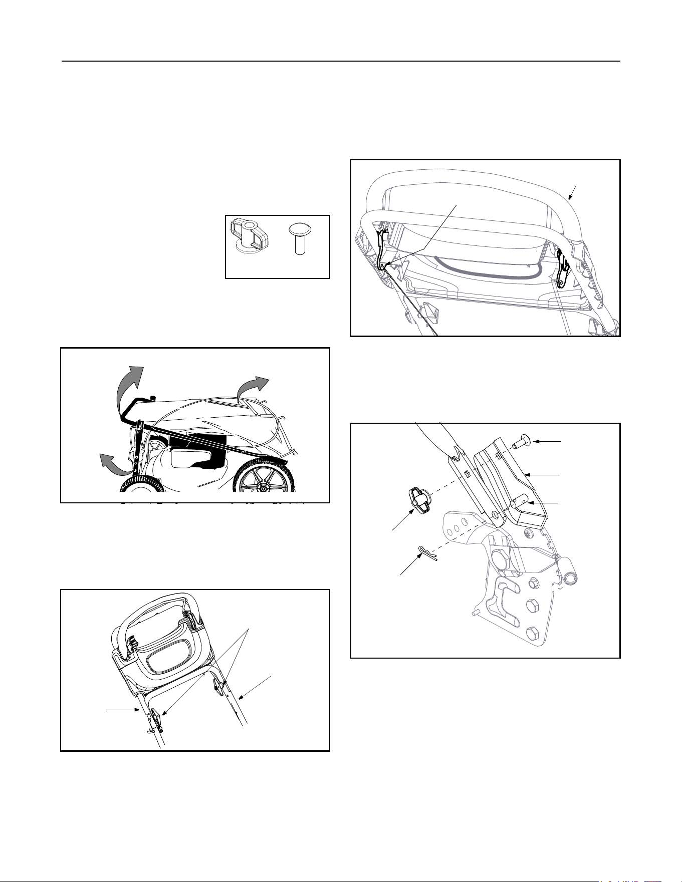
Assembling Handle
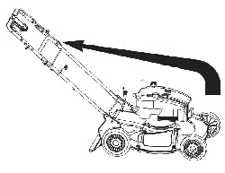
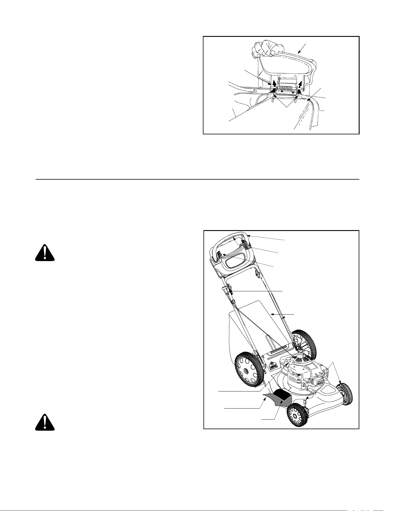
1. Remove grass bag from the unit and set it out of the
way. See Figure 1. Remove any packing material
between the handles.
Figure 1
2. Raise the lower handle in the direction shown in
Figure 1 till it snaps into place.
3. Raise the upper handle in the direction shown in
Figure 1.
4. Tighten the wing nuts shown in Figure 2.
Figure 2
NOTE: Route the cables inside the lower handle. Also
do not crimp the cables while lifting the handle up.
5. Pull the drive control bar all the way back.
6. While holding the drive control bar, hook the “Z”
end of the drive cable into the bottom hole of the
drive control bar from inside to outside. See Figure
3 .
Figure 3
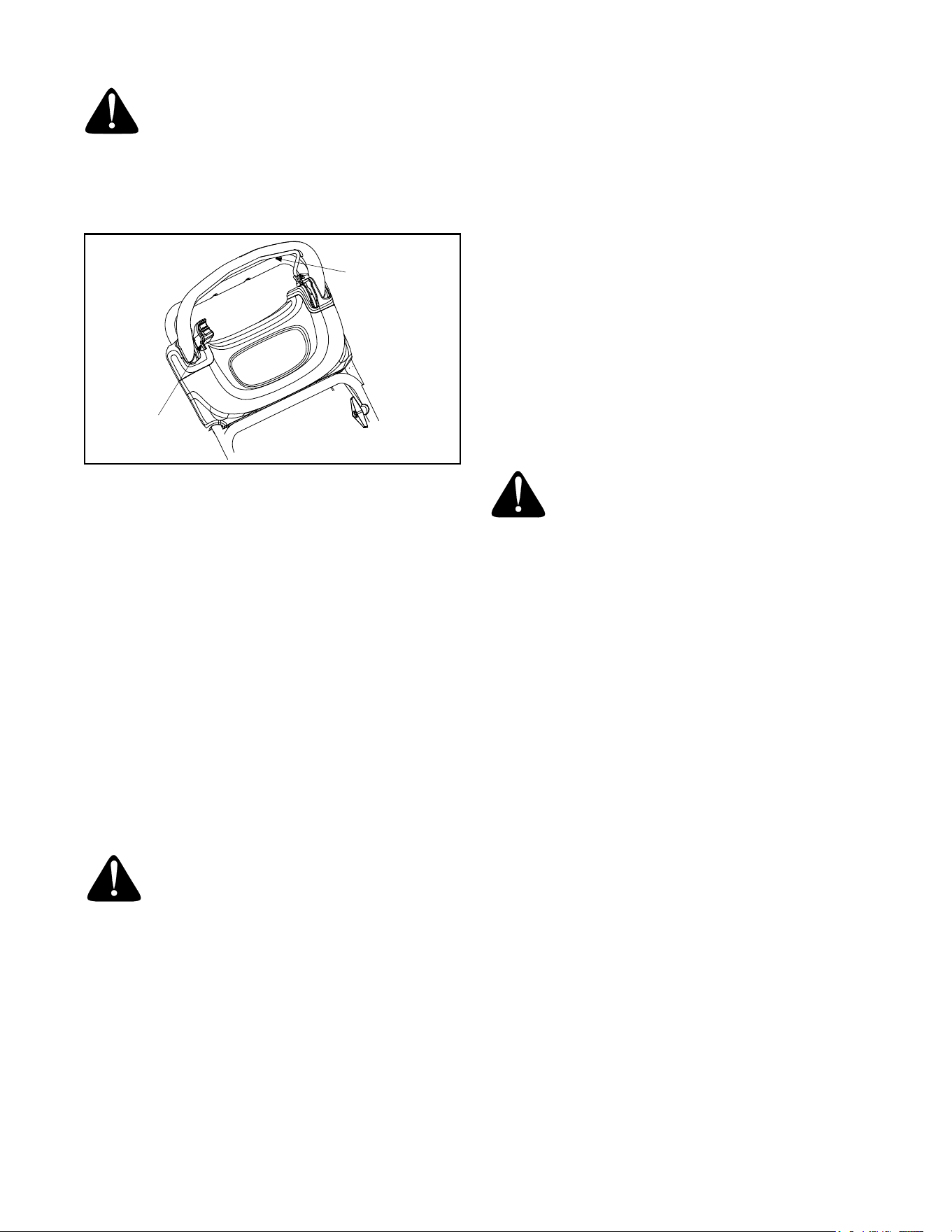
7. Remove the hairpin clip from the outer hole of the
weld pin on the lower handle. See Figure 4.
8. Using a pair of pliers, insert this clip into the inner
hole on the weld pin. Repeat on other side. See
Figure 4.
Figure 4
9. Insert carriage bolt from the hardware pack into the
upper hole on the handle mounting bracket. See
Figure 4 for direction of the carriage bolt.
10. Secure with plastic wing nut from the hardware
pack. Repeat on the other side.
11. Attach cables to the lower handle with the two cable
ties already on the lower handle. Insert pegs on
cable ties into the holes on the lower handle. Pull
cable ties tight and cut off the extra.
Wing
Carriage
Bolt (2)
Nut (2)
1. Move bag
2. Lift lower
3. Lift upper
handle
away
handle
Upper
Handle
Lower
Handle
Tighten these
wing nuts
Insert Z fitting
Drive Control
Bar
Carriage
Bolt
Weld Pin
Handle
Mounting
Bracket
Wing Nut
Hairpin
Clip
8
Attaching Drive Adjuster Block
The drive adjuster block is attached to the drive cable.
1. Remove bolt attached to the lower left handle.
2. Align the drive adjuster block with hole in handle. Its
curved side goes against the handle,
3. Secure drive adjuster block with the bolt previously
removed. See Figure 5 .
Figure 5
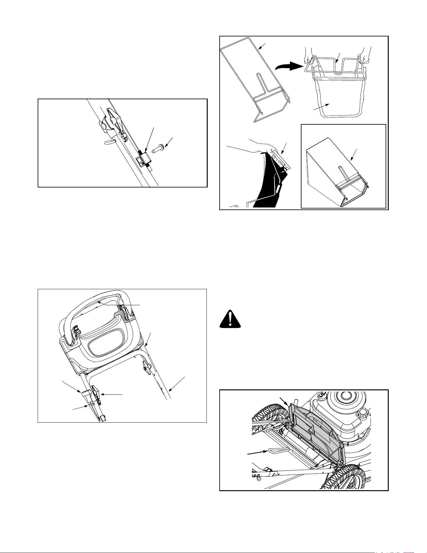
Attaching Starter Rope
The rope guide is already attached to the right side of
the lower handle of your mower. See Figure 6 .
1. With spark plug wire disconnected and grounded,
hold the blade control bar against the upper handle,
and pull the starter rope out of the engine.
2. Slip the rope through the rope guide as shown
below. Tighten the wing nut holding the rope guide
to the handle.
Figure 6
Assembling Grass Catcher
NOTE: If the grass catcher came pre-assembled,
proceed to the next section. If not, follow the steps
below to assemble it before attaching to the mower.
1. Insert frame into grass bag with the black plastic
side on the bottom of bag. See Figure 7.
Figure 7
2. Slip the side openings on the plastic channel of the
grass bag over the hooks on the grass catcher
frame. Secure bag to the frame by working the six
plastic channels.
IMPORTANT:
Entire channel except the center top of the
bag attach from outside of bag. The center top of the
bag attaches from inside of bag. See Figure 7.
Attaching Grass Catcher
1. Lift the rear discharge door and place the grass
catcher on the pivot rod. Let go of the discharge
door so that it rests on the grass catcher. See
Figure 8.
Figure 8
Bolt
Drive
Adjuster
Block
Wing Nut
Rope
Guide
Starter
Rope
Blade Control Bar
Upper Handle
Lower Handle
WARNING: If using the grass catcher, the
hooks on the grass catcher must be firmly
seated on the chute pivot rod, and the rear
discharge door must rest firmly on top of the
grass catcher.
Grass Catcher
Frame
Insert frame
into bag
Grass
Plastic
Channel
Grass Catcher
Assembly
Complete
Bag
Rear Discharge
Door
Grass
Catcher
9
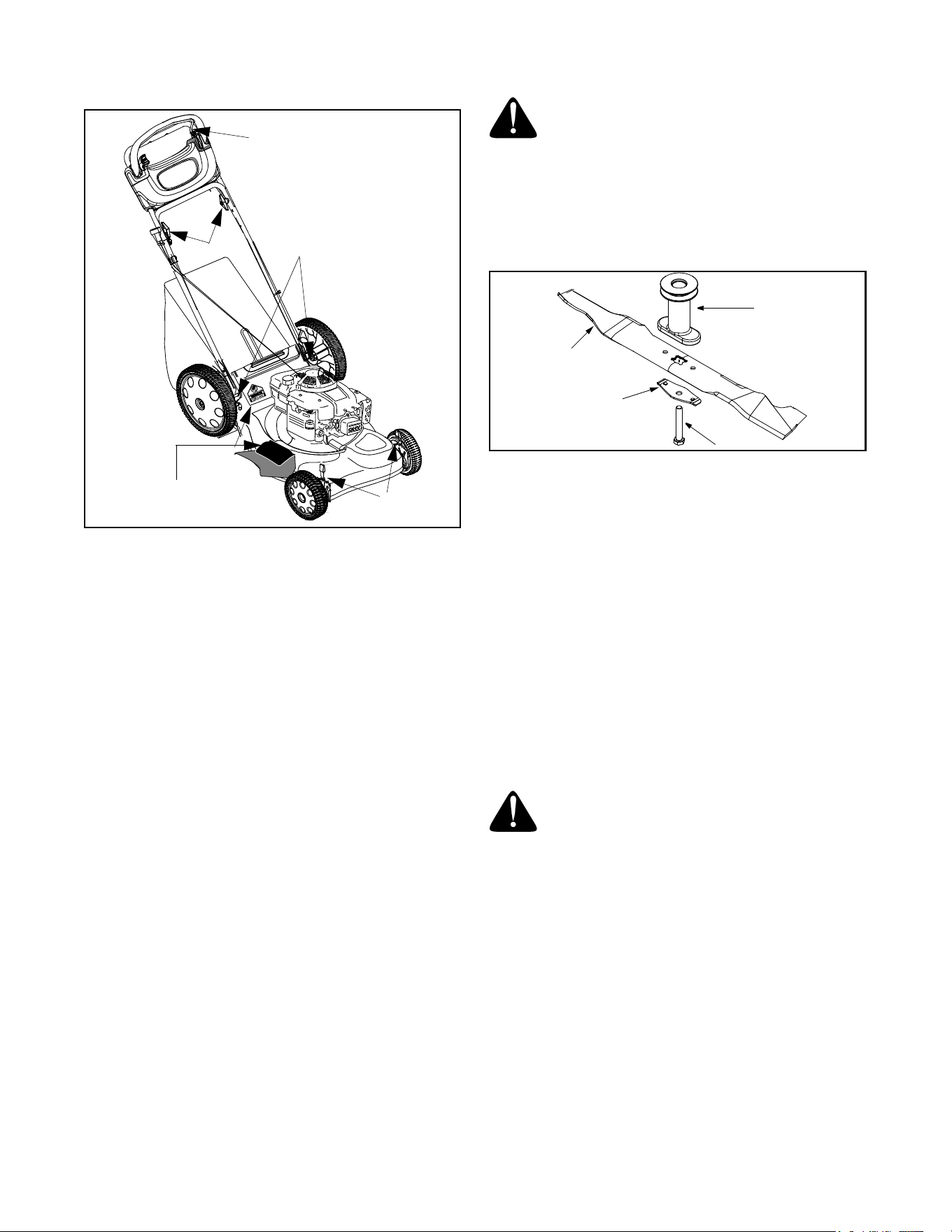
Converting To Mulcher
1. Lift the rear discharge door on the mower and lift
the grass catcher up. Release the discharge door
to allow it to close the rear opening of the mower.
Converting To Side Discharge
1. Make sure the grass catcher is off the unit and the
rear discharge door is closed. Refer to Figure 9.
2. On the side of the mower, lift the mulching plug.
See Figure 9.
3. Slide the two hooks of the side-discharge chute
under the hinge pin on the mulching plug assembly.
Lower the side mulching plug.
4. Do not remove the side mulching plug at any time,
even when you are not mulching.
Figure 9
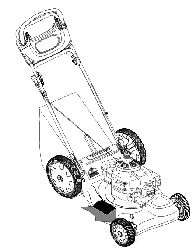
SECTION 4: KNOW YOUR LAWN MOWER
Read this owner’s manual and safety rules before
operating your lawn mower. Compare the illustrations
in Figure 10 with your lawn mower to familiarize
yourself with the location of various controls and
adjustments. Save this manual for future reference.
Drive Control Bar
This mower is equipped with Smart Speed™
transmission which enables the drive control bar to
adjust the mowing speed automatically with your
walking. The drive control bar is located on the upper
handle. Push the bar forward to engage drive, pull it
backwards to stop. The farther the bar is pushed
forward, the faster the mower will propel.
Blade Control Bar
The blade control bar is located on the upper handle of
the mower. The blade control bar must be depressed in
order to operate the unit. Release the blade control bar
to stop the engine and the blade and to energize the
self starter.
Starter Rope
The starter rope is attached to the handle. Stand behind
the unit and pull the starter rope to start the unit.
Grass Catcher Bag
The grass bag is used for collecting grass clippings.
Attach it to the mower for this purpose, but remove it
when the intention is to mulch the grass.
Figure 10
Mulching Plug
The mulching plug is used only for mulching purposes.
Instead of collecting the grass clippings in a grass
catcher, your mower has the option of recirculating the
clippings back to the lawn. This is called mulching.
Hinge Pin
Mulching Plug
Hooks
Deflector
(Slide hooks under the two
sides of hinge pin)
WARNING: The operation of any lawn
mower can result in foreign objects being
thrown into the operator’s eyes thus causing
severe eye damage. Always wear safety
glasses while operating the mower, or while
performing any adjustments or repairs on it.
WARNING: The blade control bar is a
safety device. Never attempt to bypass its
operations or alter it in any way.The blade
will rotate whenever the engine is running
and when the self starter is de-energized.
Drive Control Bar
Blade Control Bar
Starter Rope
Grass Catcher
Cutting Height
Adjustment
Side-Discharge
Chute
Mulching
Plug
Levers
Start Control Lever
Safety
Key

10
Cutting Height Adjustment Lever
These levers are located on each wheel and they are
used to adjust the cutting height. All four levers have to
be at the same relative position to ensure uniform cut.
Safety Key
The safety key is located on the engine. See Figure 10.
The safety key is a safety device used to activate and
deactivate the self starter system. The self starter
system will not work without the key in it’s proper
position. See your engine manual for more information
on the safety key.
NOTE: The safety key must be in the run position to
start the mower for both systems, either the self starter
or recoil starter.
Start Control Lever
The start control lever is located on the upper right side
of the upper handle. See Figure 10. The start control
lever must be depressed fully while pulling the blade
control bar toward upper handle for the engine to start.
The start control lever will automatically return to the
off/up position once the blade control bar is released.
NOTE: The starter control lever must be depressed to
start the engine either with the self starter or recoil
starter system.
SECTION 5: OPERATING YOUR LAWN MOWER
Gas & Oil Fill-Up
• Check oil level and add oil if necessary. Follow
relevant instructions in the engine manual for this.
• Service the engine with gasoline as instructed in
the engine manual.
Before Starting Mower
• Attach spark plug wire to spark plug. Make certain
the metal cap on the end of the spark plug wire
(inside the rubber boot) is fastened securely over
the metal tip on the spark plug.
First Time Starting Engine
NOTE: Use recoil starter rope to start engine for the
very first time. The mower is shipped with the safety key
in the locked position and the self starter in the de-
energized mode. Follow instructions as follows:
1. Place lawn mower on a level surface outdoors.
2. Remove plastic wrap under fuel cap.
3. Check oil level.
4. Add fuel.
5. Open shut off valve (if equipped) 1/4 turn.
6. Push spark plug wire firmly on spark plug.
7. Turn self starter safety key 1/4 turn clockwise to
RUN position.
8. Firmly push primer bulb 3 times.
9. While standing at upper handle, depress the starter
control lever fully with the thumb of your right hand.
10. Using your left hand, pull the blade control bar all
the way toward the upper handle.
11. Release the lever.
12. Grasp the recoil rope starter handle with your right
hand and slowly pull towards you until you feel a
slight resistance, then pull firmly until your arm is
fully extended.
13. If engine does not start by second pull, repeat steps
8, 9 10,11 and 12.
Second Time Starting Engine
NOTE: Follow these instructions if the self starter is
already in the energized mode.
WARNING: Use extreme care when
handling gasoline. Gasoline is extremely
flammable and the vapors are explosive. Never
fuel the machine indoors or while the engine is
hot or running. Extinguish cigarettes, cigars,
pipes and other sources of ignition.
WARNING: Be sure no one other than the
operator is standing near the lawn mower while
starting engine or operating mower.
WARNING: Never run engine indoors or in
enclosed, poorly ventilated areas. Engine
exhaust contains carbon monoxide, an
odorless and deadly gas.
WARNING: Keep hands, feet, hair and
loose clothing away from any moving parts on
engine and lawn mower.
11
WARNING: NEVER assume starter is in
the de-energized mode, even if the key is in
the locked position and or removed from the
engine. ALWAYS de-energize starter prior to
performing any maintenance or service to the
engine and or mower. Follow instructions on
the engine and or machine to de-energize
starter.
Figure 11
1. Check oil level and add fuel, if necessary.
2. Open shut off valve (if equipped) 1/4 turn.
3. Turn safety key 1/4 turn clockwise to RUN position.
4. Firmly push primer bulb 3 times (For a cold engine
only!).
5. While standing at upper handle, depress the starter
control lever with the thumb of your right hand.
6. Using your left hand, pull the blade control bar all
the way toward the upper handle. See Figure 11.
Starter will de-energize and engine will start.
(NOTE: If engine does not start, release blade
control bar and follow steps 8, 9, 10, 11 and 12 in
the “First Time Starting Engine” instructions.)
NOTE: If any problems are encountered, refer to the
Trouble Shooting Guide for helpful information.
To Stop Engine and Blade
WARNING: The blade will continue to
rotate for three seconds after the blade
control bar is released.
1. Release safety blade control bar (the start control
lever will automatically return to the off/up position),
engine and blade will stop within a few seconds.
NOTE: Engine may stop with a ratcheting sound. This
sound is the self starter being reactivated/energized for
the next start.
2. Turn safety key 1/4 turn counterclockwise to LOCK
position. Remove key and store in a safe place.
To De-Energize Self Starter
• Remove spark plug wire from spark plug.
• Turn safety key to RUN position (1/4 turn
clockwise).
• While standing in the operating position, depress
the starter control lever fully with the thumb of your
right hand.
• Using your left hand, pull the blade control bar all
the way toward the upper handle. (Release lever
and wait until blade and starter stop rotating).
• Release safety blade control handle (the start
control lever will automatically return to the off/up
position).
• Remove safety key.
NOTE: Engine will crank over upon actuating
equipment starting controls, but will not spark if spark
plug wire was removed from spark plug as described
above. Once engine has stopped cranking, self starter
is de-energized.
WARNING: Self Starting System: If these
instructions are not followed, amputation or
severe laceration can result.
• ALWAYS disconnect spark plug, de-energize
starter, lock and remove safety key BEFORE
performing ANY service to the engine or mower.
• DO NOT attempt any maintenance or repairs to the
self starter.
• NEVER assume starter is de-energize, even if key
is in LOCK AND REMOVE position and/or removed
from engine.
IMPORTANT:
BEFORE removing grass or other debris
from under mower deck; BEFORE changing oil, air filter
or spark plug; BEFORE removing blade for servicing;
BEFORE performing any other service to engine or
mower; BEFORE transporting mower-ALWAYS DE-
ENERGIZE SELF STARTER.
NOTE: See your engine manual packed with your unit
for more detailed instructions.
Using Your Lawn Mower
• You can use your mower as a mulcher or a rear
bagger or for side discharge of grass.
• Be sure that the lawn is clear of stones, sticks, wire,
or other objects which could damage lawn mower
or engine. Such objects could be accidently thrown
by the mower in any direction and cause serious
personal injury to the operator and others.
• For best results, do not cut wet grass because it
tends to stick to the underside of the mower.
•For a healthy lawn, always cut off one-third or less
of the total length of the grass. Lawn should be
trimmed in fall as long as there is growth.
Blade Control
Bar
Starter Control
Lever

12
Adjusting Cutting Height
Refer to height adjustments section of this manual on
page 15 for instruction on how to adjust the cutting
height and the handle height.
For best results in mowing, keep the cutting height
position high until you can determine a suitable height.
Bagging Grass Clippings
You can use the grass catcher bag to collect clippings
while you are operating the mower.
• Attach grass catcher following instructions on page
8. Grass clippings will automatically collect in the
bag as you run the mower. Operate the mower till
the grass bag is full.
• Once the bag is full, stop the engine and the mower
completely. Lift discharge door and pull grass bag
up and away from the mower to dispose of the
grass clippings.
SECTION 6: MAINTAINING YOUR LAWN MOWER
WARNING: Be sure to disconnect the
spark plug wire and de-energize starter
before performing any repairs or
maintenance. DO NOT attempt any
maintenance or service to the engine and or
mower equipped with the safety key in the
unlocked and or energized mode.
WARNING: NEVER assume starter is de-
energized, even if the key is in the locked
position and/or removed from the engine.
ALWAYS de-energize starter prior to
performing any maintenance or service to
the engine and or mower. Follow instructions
on the engine and or machine to de-energize
starter. Always observe safety rules when
performing any maintenance.
Cleaning Mower
The underside of the mower deck should be cleaned
after each use to prevent any build-up of grass
clippings, leaves, dirt, or other debris. If this debris is
allowed to accumulate, it will result in rust and
corrosion.
NOTE: We do not recommend the use of pressure
washers or garden hose to clean your unit. These may
cause damage to pulleys, bearings, or the engine. The
use of water will result in shortened life and reduce
serviceability.
• Disconnect spark plug wire.
• Drain the gasoline from the lawn mower, or place a
piece of plastic under the gas cap.
• Tip the mower so that it rests on the housing. Keep
the side with the air cleaner facing up. Hold the
mower firmly.
• Scrape and clean the underside of the deck with a
suitable tool. Do not spray with water.
• Put the mower back on its wheels on the ground. If
you had put plastic under the gas cap, make sure to
remove it now.
Engine Care
A list of key maintenance jobs required for good
performance by the mower is given below. Follow the
accompanying engine manual for a detailed list and
instructions.
• Change engine oil regularly, as instructed in the
engine manual. Check oil level before starting
engine every time.
• Service air cleaner regularly. You may have to
service this more frequently if you are operating the
mower under extremely dusty conditions.
• Clean the engine periodically. Remove dirt and
debris with a cloth or brush.
• Clean the spark plug and reset the gap to.030” at
least once a season. Refer to the engine manual for
correct spark plug type.
• Inspect muffler periodically, and replace if
necessary. Damaged mufflers or spark arresters
can create a fire hazard.
WARNING: If the mower strikes a foreign
object, stop the engine. Remove spark plug
wire from the spark plug and thoroughly inspect
for any damage. Repair the damage promptly
before restarting and operating the mower.
WARNING: Never tip the mower more than
90 degrees in any directions and do not leave
the mower tipped for any length of time. Oil can
drain into the upper part of the engine causing
a starting problem.
WARNING: Avoid muffler and surrounding
areas while the mower engine is hot because
temperature of these areas of the engine may
exceed 150
o
F.
13
Lubrication
Figure 12: Lubrication Chart
Wheels
• Lubricate the wheels and bearings, if so equipped,
at least once a season with light oil or engine oil.
Also if the wheels are removed for any reason,
lubricate the surface of the pivot arm axle and the
inner surface of the wheel with light oil.
Mulch Plug & Rear Discharge Door
• Lubricate the torsion spring and the pivot point on
each end of the rear discharge door using a light oil.
Transmission
• The transmission is pre-lubricated and sealed at
the factory and does not require lubrication on a
regular basis as part of maintenance.
Blade Control
• Lubricate the pivot points on the blade control bar
and the brake cable at least once a season with a
light oil. It needs to move in both directions.
Engine
• Follow the engine manual instructions and
recommended schedule for lubricating engine
components.
Blade Care
Periodically inspect the blade adapter and pulley for
cracks, especially if you strike a foreign object. Replace
when necessary.
1. Disconnect spark plug wire from spark plug.
2. Turn mower on its side making sure that the air filter
and the carburetor are up.
3. Remove the hex bolt which holds the blade
adapter-pulley assembly to the engine crankshaft.
See Figure 13 . Remove the pulley assembly and
the bell support from the crankshaft.
4. Remove blade from the blade adapter and pulley.
Figure 13
5. Before reinstalling the blade-pulley assembly to the
unit, lubricate the engine crankshaft and the inner
surface of the blade adapter with light oil.
6. Also lubricate the bolt hole and the hex bolt.
7. Insert the hex bolt, earlier removed, through the
center holes on the blade bell support and the
blade adapter-pulley assembly respectively.
8. Install the blade assembly on the crankshaft.
Tighten the hex bolt to the recommended torque.
Blade Mounting Torque:
Center bolt: 450 in.lbs. minimum, 600
in.lbs. maximum.
IMPORTANT:
The bolt used to secure the blade to the
engine is specially heat-treated. Do not substitute. To
order replacement bolt, refer to page 17.
9. Sharpen the blade with a file or on a grinding wheel.
Do not attempt to sharpen the blade while it is still
on the mower.
10. Follow the original angle of grind as a guide. Make
sure that each cutting edge receives an equal
amount of grinding to prevent an unbalanced blade.
NOTE: An unbalanced blade will cause excessive
vibration when rotating at high speeds, and may cause
damage to the mower and could break, causing
personal injury. Test the blade by balancing it on a
round shaft screwdriver or a blade balancer.
11. If the blade is not balanced, remove metal from the
heavy side until it balances evenly.
Lube
Lube
L
u
b
e
L
u
b
e
Lube
WARNING: When removing the cutting
blade for sharpening or replacement, protect
hands by using heavy gloves or a thick rag to
grasp the cutting blade.
WARNING: To ensure safe operation of
your unit, all nuts and bolts must be checked
periodically for correct tightness.
Adapter-Pulley
Assembly
Blade
Hex Bolt
Blade Bell
Support
14
SECTION 7: SERVICE & ADJUSTMENTS
WARNING: Be sure to disconnect the
spark plug wire and de-energize starter
before performing any repairs or
maintenance. DO NOT attempt any
maintenance or service to the engine and or
mower equipped with the safety key in the
unlocked and or energized mode.
WARNING: NEVER assume starter is de-
energized, even if the key is in the locked
position and/or removed from the engine.
ALWAYS de-energize starter prior to
performing any maintenance or service to
the engine and or mower. Follow instructions
on the engine and or machine to de-energize
starter. Always observe safety rules when
performing any maintenance.
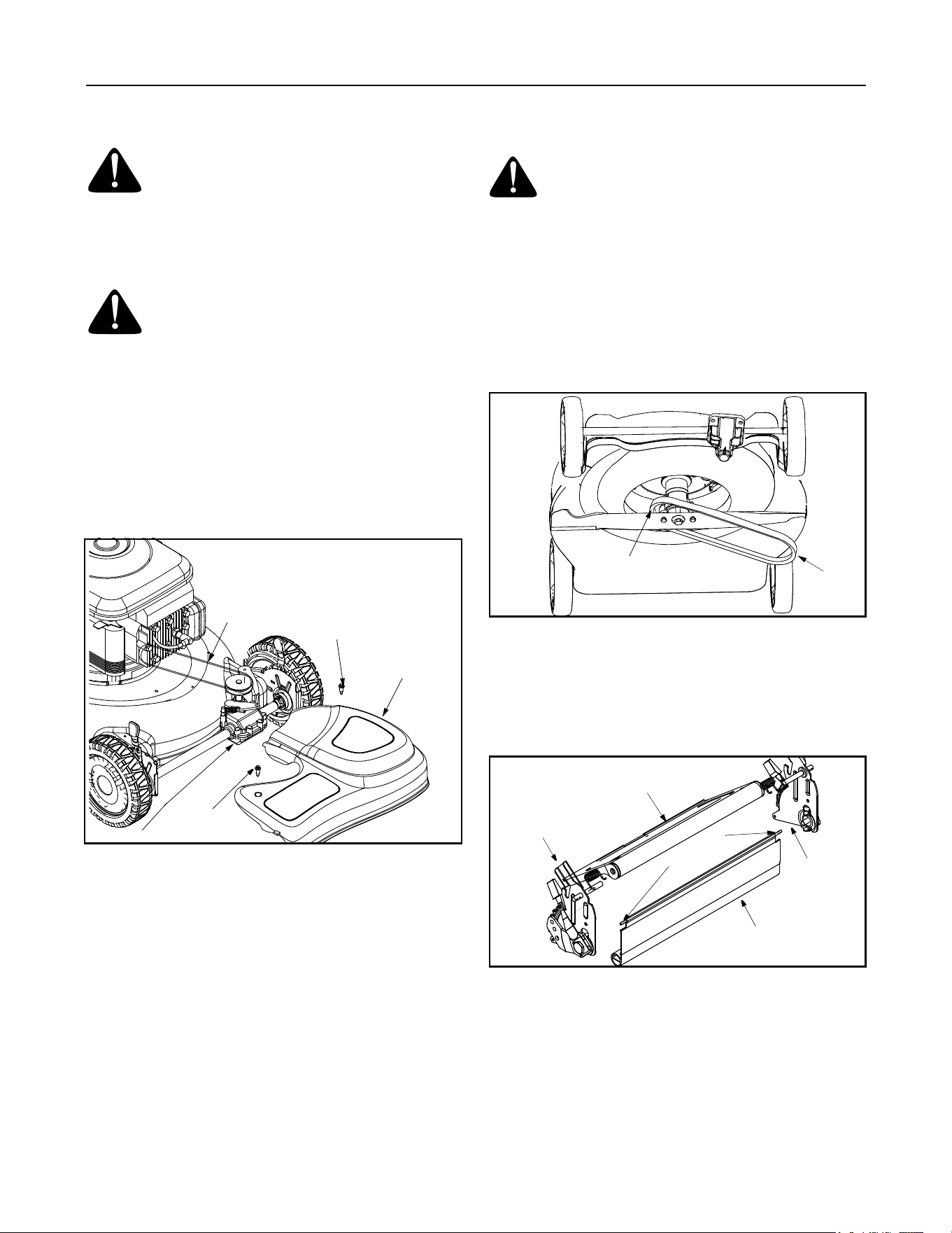
Replacing Drive Belt
1. Remove two shoulder screws securing the front
drive cover to the mower deck. See Figure 14.
Figure 14
2. Press inward on the sides of the front drive cover
and release the tabs that secure the front drive
cover to the height adjuster brackets. Remove drive
cover from the mower.
3. Remove the idler and accompanying hardware
from the idler bracket using 7/16” wrench and
socket.
4. Remove the belt from the transmission pulley.
5. Lift and stabilize the front of the deck.
6. Loosen the center hex bolt and lower the blade and
engine pulley until there is adequate clearance to
move the belt past the belt keeper.
7. Lift the mower to access the belt from the underside
of the mower.
8. Slide the belt off the engine pulley and around the
blade. See Figure 15 .
9. Replace with the new belt, working around the
blade. Make sure the belt is firmly seated on the
engine pulley while pulling from the other side and
sliding it around the transmission pulley.
Reassemble the idler bracket. Tighten all
hardware.
10. Put the mower down with all four wheels firmly
placed on one level.
Figure 15
Replacing Rear Flap
1. To remove rear flap, cut off the flat end of the wire
rod which secures it to the deck. See Figure 16 .
2. Attach the new flap and new rod to deck, bending
the ends of the new rod over to secure to deck.
Figure 16
Adjusting Handle Height
Your mower is shipped with the handle in the higher
height position.
1. Remove the starter rope from the rope guide.
2. Remove the upper handle by removing the hand
knobs and carriage bolts. Lay the upper handle out
of the way, being careful not to bend or kink cables.
3. Remove the hairpin clips from the weld pins on the
handle brackets. Refer to Figure 4 .
Shoulder
Shoulder
Screw
Screw
Front Drive
Cover
Belt
Transmission
WARNING: Use a thick piece of rag to
handle the blade while sliding the belt in the
next step. Make sure the engine does not start
at all while doing this job.
Engine Pulley
Drive
Belt
Handle
Bracket
Handle
Bracket
Rear Discharge
Door
Rear
W
i
r
e
R
o
d
Flap
15
4. Remove the carriage bolts and wing nuts from the
handle brackets. Press out on the legs of the lower
handle. Remove lower handle from the mower.
5. Turn the lower handle around so the notch on the
bottom of the lower handle is facing forward as
shown in Figure 17 . Reassemble, placing the
bottom holes in the handle over the weld pins in the
handle mounting bracket.
Figure 17
6. Reassemble the upper handle to the lower handle.
7. Place the hairpin clips in the inner holes of the weld
pins and replace the carriage bolts and wing nuts
on the handle brackets. Attach the starter rope as
instructed in the Assembly section.
Adjusting Cutting Height
An adjusting plate and thumb lever at each wheel
position provides cutting height adjustment. Each
adjusting plate has nine height positions.
1. Simply depress the lever towards wheel and move
it to any of the nine positions for the desired cutting
height. See Figure 18.
2. Place all four levers on the four wheels in the same
relative position for uniform cutting.
Figure 18
Adjusting Carburetor
If the engine is running rough, minor adjustments to the
carburetor may be required to compensate for
differences in fuel, temperature, altitude and load.
NOTE: Dirty air cleaner may cause an engine to run
rough.Before adjusting carburetor, check air cleaner.
To adjust the carburetor, please follow the
recommendations and instructions on carburetor
adjustment in the engine manual.
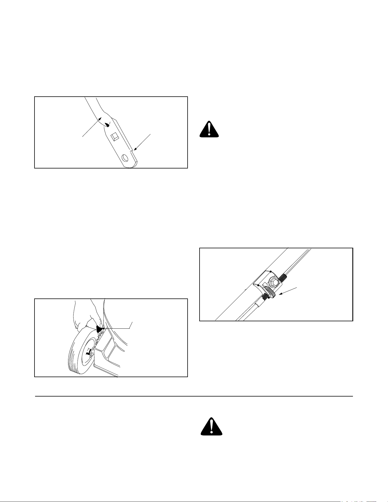
Adjusting Drive Clutch
The drive clutch adjustment wheel is located on the
lower left handle and is used to tighten or loosen
tension on the drive cable. Adjust this cable if
a. the mower does not propel itself; or
b. the wheels hesitate with the drive control bar
pushed forward.
1. To adjust, rotate the adjustment wheel with your
fingers. See Figure 19 for location of the wheel.
2. Turn the wheel to the left to tighten the drive cable.
Turn the wheel to the right to loosen the drive cable.
Figure 19
SECTION 8: OFF-SEASON STORAGE
Prepare your lawn mower for storage at the end of the
season or if the unit will not be used for 30 days or
more. Store the mower in a clean, dry area.
WARNING: Be sure to disconnect the
spark plug wire and de-energize starter
before performing any repairs or
maintenance. DO NOT attempt any
maintenance or service to the engine and or
mower equipped with the safety key in the
unlocked and or energized mode.
Notch
Lower
Handle
Height Adjustment
Lever
WARNING: If any adjustments are made to
the engine (e.g. carburetor) while the engine is
running, keep clear of all moving parts. Be
careful of heated surfaces like the muffler.
Drive Clutch
Adjustment
Wheel

16
WARNING: NEVER assume starter is de-
energized, even if the key is in the locked
position and or removed from the engine.
ALWAYS de-energize starter prior to
performing any maintenance or service to
the engine and or mower. Follow instructions
on the engine and or machine to de-energize
starter.
Mower
• Clean underside of the mower following
instructions on page 12.
• Lubricate mower as instructed on page 13.
• You can fold your mower’s handle for convenient
storage:
1. Remove the starter rope from the rope guide.
2. Loosen the two hand knobs on the sides of the
handle, and let the upper handle fold down to
the rear.
3. Move the hairpin clips to the outer hole in the
weld pins on the handle mounting brackets.
4. Spread the sides of the lower handle, and push
it forward and down.
• Inspect and replace/sharpen blade, if required.
Engine
• Follow recommendations in the engine manual for
off-season storage of the engine.
• Change oil if it has not been changed in the last
three months. For instructions on how to change oil,
refer to the engine manual.
• Clean engine and remove any grass clippings.
Other
• Do not store gasoline from one season to another.
• Replace your gasoline can if it starts to rust. Rust
and/or dirt in the gasoline will cause problems.
Store unit in a clean, dry area. Do not store next to
corrosive materials, such as fertilizer.
NOTE: If storing in an unventilated or metal storage
shed, be certain to rustproof the equipment by coating
with a light oil or silicone.
SECTION 9: TROUBLE-SHOOTING
NOTE: For repairs beyond the minor adjustments listed above, contact your local authorized service dealer.
Problem Possible Cause Corrective Action
Engine fails to start 1. Blade control bar disengaged.
2. Spark plug wire disconnected.
3. Fuel tank empty, or stale fuel.
4. Blocked fuel line.
5. Faulty spark plug.
6. Engine flooded.
7. Start control lever not depressed.
8. Safety key not in run position.
9. Self starter already de-energized.
1. Engage blade control bar.
2. Connect wire to spark plug.
3. Fill up tank with fresh gasoline.
4. Clean fuel line.
5. Clean, adjust gap, or replace.
6. Wait a few minutes to restart. Do not prime.
7. Depress start control lever.
8. Place safety key in run position.
9. Use recoil starter to start engine.
Engine runs erratic 1. Spark plug wire loose.
2. Blocked fuel line or stale fuel.
3. Vent in gas cap plugged.
4. Water or dirt in fuel system.
5. Dirty air cleaner.
1. Connect and tighten spark plug wire.
2. Clean fuel line, fill tank with fresh gasoline.
3. Clear vent.
4. Drain fuel tank. Refill with fresh fuel.
5. Clean air cleaner. Refer to engine manual.
Engine overheats 1. Engine oil level low.
2. Air flow restricted.
1. Fill crankcase with proper oil.
2. Clean lawn mower engine.
Occasional skip
(hesitates) at high
speed
1. Spark plug gap too close. 1. Adjust gap to.030 inches.
Idles poorly 1. Spark plug faulty, or gap too wide.
2. Dirty air cleaner.
1. Reset gap to.030 inches or replace spark plug.
2. Clean air cleaner.
Excessive vibration 1. Blade loose or unbalanced.
2. Bent cutting blade.
3. Bent engine crankshaft.
1. Tighten blade and adapter, balance blade.
2. Replace blade.
3. Contact the nearest service center.
Mower will not mulch
grass
1. Wet grass.
2. Excessively high grass.
3. Dull blade.
1. Wait until grass is dry to cut.
2. Mow once at a high cutting height, then mow again at
desired height.
3. Sharpen or replace blade.
Uneven cut 1. Wheels not at same height.
2. Dull blade.
1. Reposition all wheels at same height.
2. Sharpen or replace blade.
17
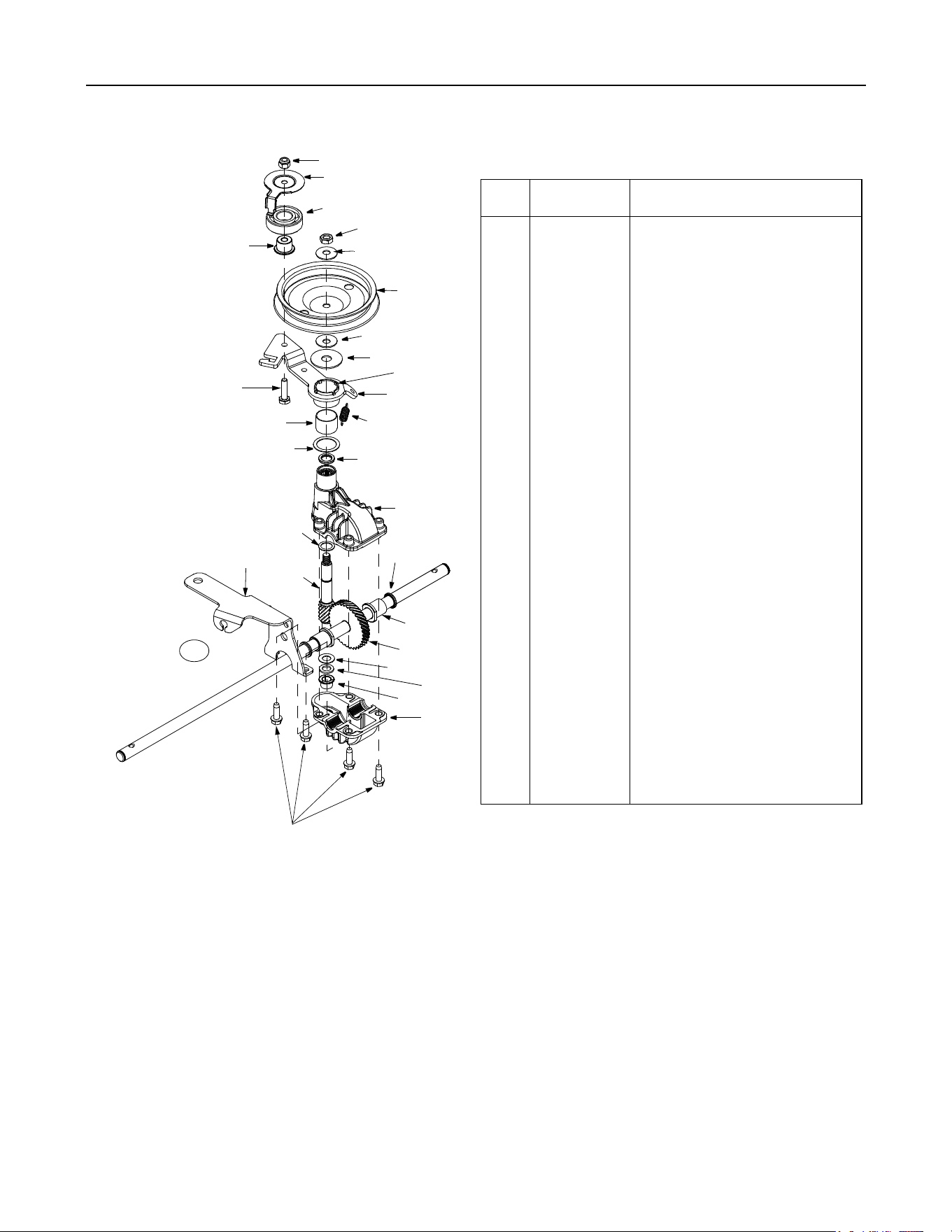
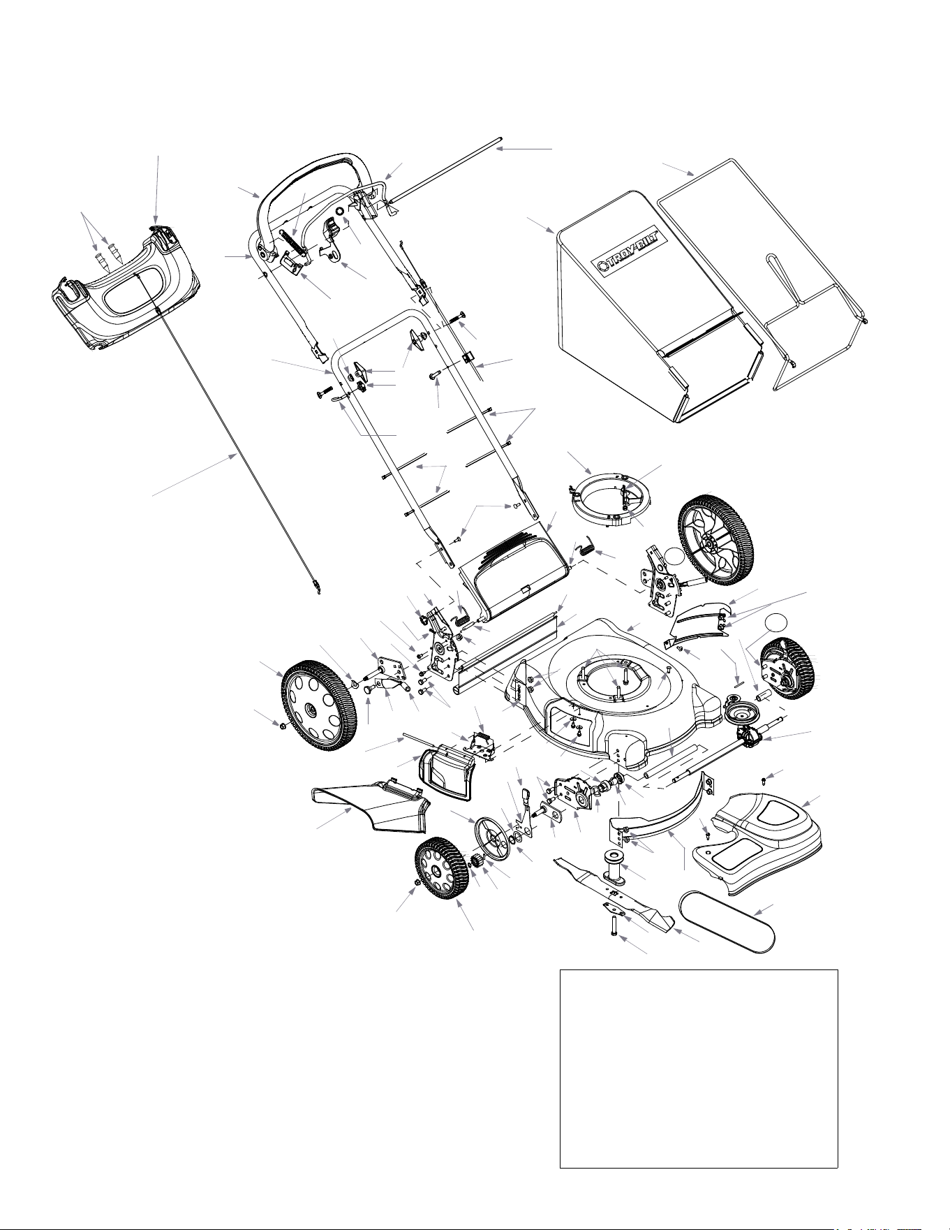
SECTION 10: PARTS LIST FOR MODEL F569
Ref
No.
Part No. Description
1.
712-0896 Lock Nut
2.
782-7598 Belt Keeper
3.
741-0124 Ball Bearing
4.
750-1050 Flange Bearing
5.
712-3025 Hex Jam Nut 5/16-24
6.
736-0425 Bell Washer.325 x.930 x.45
7.
656-0047 Pulley, 3.82 x.313 x.68
8.
736-0406 Flat Washer.422 x 1.38 x.060
9.
682-0029 Front Idler Assembly
10.
732-04001 Extension Spring
11.
741-0682A Bearing Sleeve
12.
736-0570 Fl-Wash.865 x 1.145 x.030
13.
710-0299 Hex Screw 1/4-28 x 1.0
14.
741-0699 Needle Bearing.438 x.625 x.500
15.
736-0520 Flat Washer.504 x.700 x.030
16.
717-1492 Pinion Shaft
17.
682-0030 Idler Cable Bracket Assembly
18.
721-0329 Oil Seal
19.
741-0673 Flange Bearing
20.
611-0105A Output Shaft
21.
736-0314 Thrust Washer.375 x.070 x.030
22.
736-0569 Thrust Washer.388 x.625 x.062
23.
618-0300A Upper Housing
24.
618-0299A Lower Housing
25.
710-1276 Hex Screw w/Washer 1/4-20 x.750
26.
618-04006 Transmission Assembly Comp.
27.
721-0457 Oil Seal
1
2
3
4
5
6
7
6
8
9
10
14
11
12
17
18
19
20
25
24
21
22
19
23
16
15
26
13
27
18
Model F569
IMPORTANT: For a proper working machine, use
Factory Approved Parts. V-BELTS are specially
designed to engage and disengage safely. A
substitute (non OEM) V-Belt can be dangerous by
not disengaging completely.
16
14
53
52
23
78
31
79
45
80
62
60
61
32
63
47
18
4
5
2
3
55
34
83
50
51
57
90
91
93
92
84
32
82
81
75
67
66
34
24
35
85
72
70
69
68
64
49
2
20
59
29
21
28
40
41
42
44
36
86
88
89
39
34
30
34
58
33
48
37
77
34
7
8
1
11
12
22
13
15
17
54
25
71
10
NOTE: For painted parts, please refer to
the list of color codes below. Please add
the applicable color code, wherever
needed, to the part number to order a
replacement part. For instance, if a part
numbered 700-xxxx is painted powder
black, the part number to order would be
700-xxxx-0637.
Red: 0638
Powder Black: 0637
38
24
65
26
27
9
6
19
19
56
94

19
Model F569
Ref. No Part No. Description
1.
631-04025 Drive Control Bar: Red
2.
710-0599 TT Screw 1/4-20 x 0.5
3.
736-0270 Bell Washer.265 x 0.75
4.
17032A Deflector Chute Adapter
5.
732-1014 Torsion Spring
6.
647-04005 Self Start Control Assembly
7.
731-04087 Handle Panel
8.
749-1507 Upper Handle
9.
712-04016 Push Nut
10.
712-0271 Hex Nut
11.
747-2133A Blade Control Bar
12.
747-2132A Control Rod
13.
720-0279 Handle Knob
14.
720-0284 Handle Knob
15.
710-1205 Eye Bolt
16.
746-04014 Smart Speed™ Control Cable
17.
710-0487 Carriage Bolt 5/16-18 x 2.0
18.
687-02055 Mulch Plug Comp.
19.
726-0240 Cable Tie
20.
714-0104 Cotter Pin
21.
710-1008 Self-Tapping Sems Screw
22.
746-04013 Smart Speed™/SS Fwd. Drive Cable
23.
664-04011 Grassbag Assembly
24.
710-1650 Shoulder Screw # 12 -24
25.
631-0075B Engine Spacer
26.
732-04020 Extension Spring
27.
787-01038 Cable Bracket
28.
787-01006 21” Deck
29.
782-5004A RH Rear Baffle
30.
710-1017 Screw AB: 1/4-14:.625
31.
782-5003 LH Rear Baffle
32.
710-0216 Hex Screw 3/8-16 x.75
33.
732-04089 Torsion Spring LH
34.
712-0431 Hex Nut 3/8-16
35.
731-04584 Transmission Cover
36.
782-5002A Front Baffle
37.
754-0465 V-Belt
38.
710-0809 TT-Scr. 1/4-20 x 1.25
39.
750-1165 Sleeve Spacer 10.1” Lg.
40.
748-04015A Blade Adapter w/ Pulley
41.
742-0741 21” Mulching Blade
42.
736-0524A Blade Bell Support
44.
710-1257 Hex Screw 3/8-24 x 2.50
45.
749-0928A Lower Handle
47.
731-04177 Chute Deflector
48.
732-04090 Torsion Spring RH
49.
734-04018A Wheel 8 x 2.125
50.
716-0865 Snap Ring
51.
717-1762 Gear 14T RH FWD
717-1761 Gear 14T LH FWD *
52.
747-04080 Grass Bag Frame
53.
736-0451 Saddle Washer
54.
712-3005 Hex Flange Lock Nut 3/8-16
55.
710-1652 Tt Screw 1/4-20 x.625”
56.
687-02056 Handle Bracket Assembly - RH*
687-02057 Handle Bracket Assembly - LH
57.
715-0221 Dowel Pin
58.
687-02033 Handle Bracket - RH
687-02031 Handle Bracket - LH*
59.
687-02039 Pivot Bar RH
687-02040 Pivot Bar LH*
60.
732-0866 Height Adjustment Lever
61.
720-0312 Foam Grip
62.
738-0507B Shoulder Scr.500 Dia. x.434
63.
747-0710 Hinge Pin
64.
734-04019 Wheel, 12 x 2.125
65.
728-0199 Plastic Rivet
66.
732-0708 Bearing Retainer
67.
741-0604A Bearing Sleeve
68.
732-0700 Wire
69.
731-1236 Rear Trailing Shield
70.
747-0996 Pivot Rod
71.
711-1293 Belt Keeper Pin
72.
731-04134 Rear Discharge Door
75.
748-0355 Bearing Support
77.
750-04162 Spacer.375 x.50 x 1.02
78.
738-1002 Shoulder Screw 1/4-14
79.
710-0703 Carriage Bolt 1/4-20
80.
712-0397 Wing Nut
81.
736-0447 Wave Washer
82.
782-0512B Height Adjuster Plate - RH
782-0511A Height Adjuster Plate - LH*
83.
750-1166 Slev. Spacer 2.1” Lg.
84.
687-02044 Pivot Plate Assembly
85.
618-04006 Transmission Assembly
88.
682-0512A Height Adjustment Assembly RH*
682-0511A Height Adjustment Assembly LH
89.
782-7551 Wheel Dust Cap
90.
716-0102 Snap Ring
91.
736-0474 Washer
92.
720-0426 Adjustment Knob
93.
732-0706 Front Lever RH
732-0707 Front Lever LH*
94.
736-0182 Spring Washer
Ref. No Part No. Description
* Not shown in illustration

MANUFACTURER’S LIMITED WARRANTY FOR:
The limited warranty set forth below is given by Troy-Bilt LLC
with respect to new merchandise purchased and used in the
United States, its possessions and territories.
“Troy-Bilt” warrants this product against defects in material
and workmanship for a period of two (2) years commencing
on the date of original purchase and will, at its option, repair or
replace, free of charge, any part found to be defective in
materials or workmanship. This limited warranty shall only
apply if this product has been operated and maintained in
accordance with the Operator’s Manual furnished with the
product, and has not been subject to misuse, abuse,
commercial use, neglect, accident, improper maintenance,
alteration, vandalism, theft, fire, water, or damage because of
other peril or natural disaster. Damage resulting from the
installation or use of any part, accessory or attachment not
approved by Troy-Bilt for use with the product(s) covered by
this manual will void your warranty as to any resulting
damage.
Normal wear parts are warranted to be free from defects in
material and workmanship for a period of thirty (30) days from
the date of purchase. Normal wear parts include, but are not
limited to items such as: batteries, belts, blades, blade
adapters, grass bags, rider deck wheels, seats, snow thrower
skid shoes, shave plates, auger spiral rubber and tires.
HOW TO OBTAIN SERVICE: Warranty service is available,
WITH PROOF OF PURCHASE, through your local authorized
service dealer. To locate the dealer in your area, check your
Yellow Pages, or contact Troy-Bilt LLC at P.O. Box 361131,
Cleveland, Ohio 44136-0019, or call 1-866-840-6483 or 1-
330-558-7220, or log on to our Web site at www.troybilt.com.
This limited warranty does not provide coverage in the
following cases:
a. The engine or component parts thereof. These items
may carry a separate manufacturer’s warranty. Refer
to applicable manufacturer’s warranty for terms and
conditions.
b. Log splitter pumps, valves, and cylinders have a
separate one year warranty.
c. Routine maintenance items such as lubricants, filters,
blade sharpening, tune-ups, brake adjustments, clutch
adjustments, deck adjustments, and normal
deterioration of the exterior finish due to use or
exposure.
d. Service completed by someone other than an
authorized service dealer.
e. Troy-Bilt does not extend any warranty for products
sold or exported outside of the United States, its
possessions and territories, except those sold through
Troy-Bilt’s authorized channels of export distribution.
f. Replacement parts that are not genuine Troy-Bilt parts.
g. Transportation charges and service calls.
No implied warranty, including any implied warranty of
merchantability of fitness for a particular purpose,
applies after the applicable period of express written
warranty above as to the parts as identified. No other
express warranty, whether written or oral, except as
mentioned above, given by any person or entity,
including a dealer or retailer, with respect to any product,
shall bind Troy-Bilt. During the period of the warranty, the
exclusive remedy is repair or replacement of the product
as set forth above.
The provisions as set forth in this warranty provide the
sole and exclusive remedy arising from the sale. Troy-Bilt
shall not be liable for incidental or consequential loss or
damage including, without limitation, expenses incurred
for substitute or replacement lawn care services or for
rental expenses to temporarily replace a warranted
product.
Some states do not allow the exclusion or limitation of
incidental or consequential damages, or limitations on how
long an implied warranty lasts, so the above exclusions or
limitations may not apply to you.
In no event shall recovery of any kind be greater than the
amount of the purchase price of the product sold. Alteration
of safety features of the product shall void this warranty.
You assume the risk and liability for loss, damage, or injury to
you and your property and/or to others and their property
arising out of the misuse or inability to use the product.
This limited warranty shall not extend to anyone other than
the original purchaser or to the person for whom it was
purchased as a gift.
HOW STATE LAW RELATES TO THIS WARRANTY: This
limited warranty gives you specific legal rights, and you may
also have other rights which vary from state to state.
IMPORTANT:
Owner must present Original Proof of
Purchase to obtain warranty coverage.
Troy-Bilt LLC, P.O. BOX 361131 CLEVELAND, OHIO 44136-0019; Phone: 1-866-840-6483, 1-330-558-7220