
Loading ...
Loading ...
Loading ...
Part 1 – Introduction
9
• Lens
Features a xed focus lens.
• Factory Reset Button
Restores the camera's default factory settings. For
more information, refer to the Factory Reset.
• Bottom Cover
Allows you to install the camera on a wall or a ceiling.
• Network Port
Connect a network cable with an RJ-45 connector to
this port. If using a PoE switch, you can supply power
to the camera using an ethernet cable. For more
information on PoE switch use, refer to the switch
manufacturer's operation manual. You can congure,
manage, and upgrade this camera and monitor its
images from a remote computer over the network.
For more information on network connection setup,
refer to the IDIS Discovery operation manual.
The following table describes the network cable
specications.
<The network cable specications>
Item Content Note
Connector RJ-45
Ethernet 10/100 Base 10/100 Mbps
Cable
UTP Category 5e or
higher
Maximum
length
100m
PoE IEEE 802.3af, Class 3
• SD Memory Card Slot
Used to insert a microSD memory card into the
camera. (An SLC (Single Level Cell) or MLC (Multi Level
Cell) card by SanDisk or Transcend is recommended)
• Do not remove the SD memory card while the
system is in operation. Removing the card while
the system is in operation can cause the system
to malfunction and/or corrupt data stored on the
SD memory card.
• An SD memory card is a consumable product
with a nite service life. Prolonged use will
damage the card's memory sectors and result
in data loss or memory card failure. Test the SD
memory card regularly and replace it whenever
necessary.
• Cable Access Hole
For routing cables.
• Audio
- O (Out): Connect an amplier to this port (line
out). This device does not feature a built-in audio
amplier unit and therefore requires the user to
purchase a separate speaker system with a built-in
amplier.
- I (In): Connect an audio source to this port. (Line in)
A built-in microphone is featured on the front.
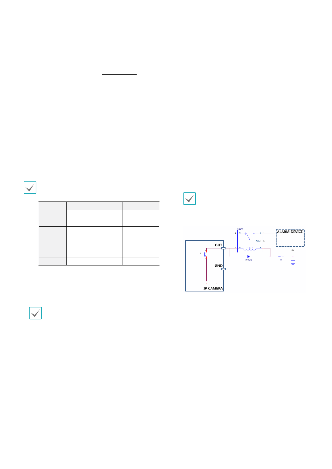
• Alarm
- O (Out): It is the BJT (Bipolar Junction Transistor)
- open collector output. If the voltage and current
exceed the specication limit (Max. Load: 30mA,
Max. Voltage: 5VDC), the product could be
damaged. When connecting the device which
exceeds the specication limit, refer to the picture
(circuit) below.
If used with an external inductive load(e.g. relay),
a diode must be connected in parallel with the
load for protection. Otherwise, the product could
be damaged.
- I (In): Connect an alarm-in device to this port.
(Mechanism: Choose between an NC (Normally
Closed) type or an NO (Normally Open) type) →
Connect a mechanical or electrical switch to the
alarm in port and the GND (ground) connector.
Alarm in range is 0V to 5V. In order to detect alarm
input from an electrical switch, the signal must be
higher than 4.3V from an NC switch or less than
0.3V from an NO switch and must last for longer
than 0.5 seconds.
Loading ...
Loading ...
Loading ...