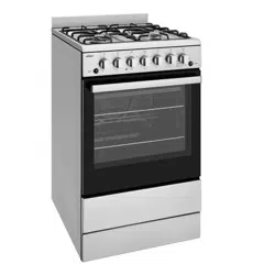

540MM UPRIGHT COOKERS
User Manual
CFE532, CFE533, CFE535, CFE536, CFE537, CFE547,
CFG501, CFG503, CFG504, CFG505, CFG513,
CFG517
cooking
The Chef in Aussie kitchens for
over 70 years
Enjoy peace of mind.
Register your appliance today.
Stay updated on better living services, safety notices and shop for
accessories.
1. Open the camera app on your smartphone and point at
the QR code to scan
Product Registration QR code is located on the front of
your appliance or inside the door rim*.
2. Tap the notification or link to open the registration form
3. Complete your details and enjoy peace of mind
*Exact location of QR code may vary depending on oven model
2 Chef 540 Upright Cooker
CONGRATULATIONS
Congratulations and thank you for choosing your Chef upright
cooker. We are sure you will find your new appliance a
pleasure to use and a great asset to your cooking. Before
you use the appliance, we recommend that you read through
the whole user manual which provides a description of the
product and its functions. For future reference, please store this
booklet in a safe place.
To avoid the risks that are always present when you use a
gas appliance, it is important that the appliance is installed
correctly and that you read the safety instructions carefully to
avoid misuse and hazards.
This appliance complies with the requirements of Australia
standards AS/NZS 60335.2.6 and AS/NZS 5263.
CONDITIONS OF USE
This appliance is intended to be used in household andsimilar
applications such as:
•Staff kitchen areas in shops, offices and other working
environments
•Farm houses
•By clients in hotels, motels and other residential type
environments
•Bed and breakfast type environments.
Record model and serial number here:
Model:
..................................................................
Serial number: ........................................................
The symbols you will see in this booklet have these meanings:
warning
This symbol indicates information concerning your personal safety
caution
This symbol indicates information on how to avoid damaging
the appliance
tips and information
This symbol indicates tips and information about use of the
appliance
environmental tips
This symbol indicates tips and information about economical
and ecological use of the appliance
Important – check for any damage or marks
If you find the appliance is damaged or marked, you must
report it within 7 days if you wish to claim for damage/
marks under the manufacturer’s warranty. This does not affect
your statutory rights.
Information on disposal for users
•Most of the packing materials are recyclable. Please dispose
of those materials through your local recycling depot or by
placing them in appropriate collection containers
•If you wish to discard this product, please contact your
local authorities and ask for the correct method of disposal.
Important Information that may impact your
Manufacturer’s Warranty
Adherence to the directions for use in this manual is
extremely important for health and safety. Failure to strictly
adhere to the requirements in this manual may result in
personal injury, property damage and affect your ability
to make a claim under the Chef manufacturer’s warranty
provided with your product. Products must be used,
installed and operated in accordance with this manual.
You may not be able to claim on the Chef manufacturer’s
warranty in the event that your product fault is due to
failure to adhere this manual.
Contents
Important safety instructions
...........................................3
Installation
..................................................................4
Gas conversion instructions
..........................................11
Operating for the first time
...........................................18
Installing your oven accessories
....................................19
Using the gas cooker
.................................................20
Using the electric cooker
.............................................22
General hints and tips ................................................24
Cleaning the cooker
..................................................26
Getting to know your oven
..........................................30
Oven guide
..............................................................31
Troubleshooting
.........................................................32
Warranty
.................................................................34
Chef 540 Upright Cooker 3
Important safety instructions
To avoid an electric shock or fire
This appliance is NOT intended for use by persons
(including children) with reduced physical, sensory or
mental capability, or lack of experience and knowledge,
unless they have been given supervision or instruction
concerning use of the appliance by a person responsible
for their safety.
WARNING - Accessible parts may become hot during use.
To avoid burns, young children should be kept away.
Young children should be supervised to ensure they do not
play with this appliance.
DO NOT operate the hotplates with external timers or separate
remote control system.
During use this appliance becomes hot. Care should be
taken to avoid touching hot external, internal surfaces and
hot elements when in use. Use oven gloves.
This appliance must NOT be used as a space heater.
DO NOT install an after market lid or cover over this appliance.
DO NOT spray aerosols in the vicinity of this appliance
while it is in operation.
DO NOT use or store flammable materials in the appliance
(incl storage drawer) or near this appliance.
Ensure all specified vents, openings and airspaces are not
blocked
Install cooker, shelving and fittings in accordance with the
Guide and Installation Instructions, to avoid accidents.
DO NOT operate the gas appliance if the smell of gas
persists.
DO NOT MODIFY THIS APPLIANCE.
The cooking process has to be supervised. A short term
cooking process has to be supervised continuously.
DO NOT install this appliance behind a decorative door in
order to avoid overheating
DO NOT use this appliance as a space heater
Grill warnings
DO NOT leave grill on unattended.
Fat left on a grill dish is a fire hazard! Keep grill clean and
turn off grill immediately after use.
If gas burner does not light in 15 seconds, allow one
minute for gas to clear before trying again.
Placing thick portions of food under grill can be a fire
hazard.
DO NOT cover the grill dish insert with foil.
Separate grill model: Grill with door open
Grill in oven model: Grill with door closed
Oven warnings
DO NOT use oven door as a shelf.
DO NOT push down on open oven door.
If the gas oven does not light in 8 seconds, allow 1 minute
for gas to clear before trying again.
DO NOT line oven with foil or place anything on the
bottom of the oven while baking, as trapped heat will
crack or craze the floor of the oven cavity liner.
DO NOT use poly-unsaturated oils (vegetable oils) as this
type of oil can cause black spots or deposits inside the
oven. This residue is very difficult to remove.
Hotplate and burner warnings
DO NOT allow pots to boil dry, as damage to hotplate
(and pan) may result.
DO NOT operate without a pot, fry pan etc on hotplates.
DO NOT allow cookware to overhang hob onto adjacent
bench tops, this will cause scorching to the bench top
surface.
Gas models: Ensure burner caps and crowns are in their
correct position.
Do not store items on the cooking surface, to avoid fire.
Unattended cooking on a hob with fat or oil can be
dangerous and may result in a fire.
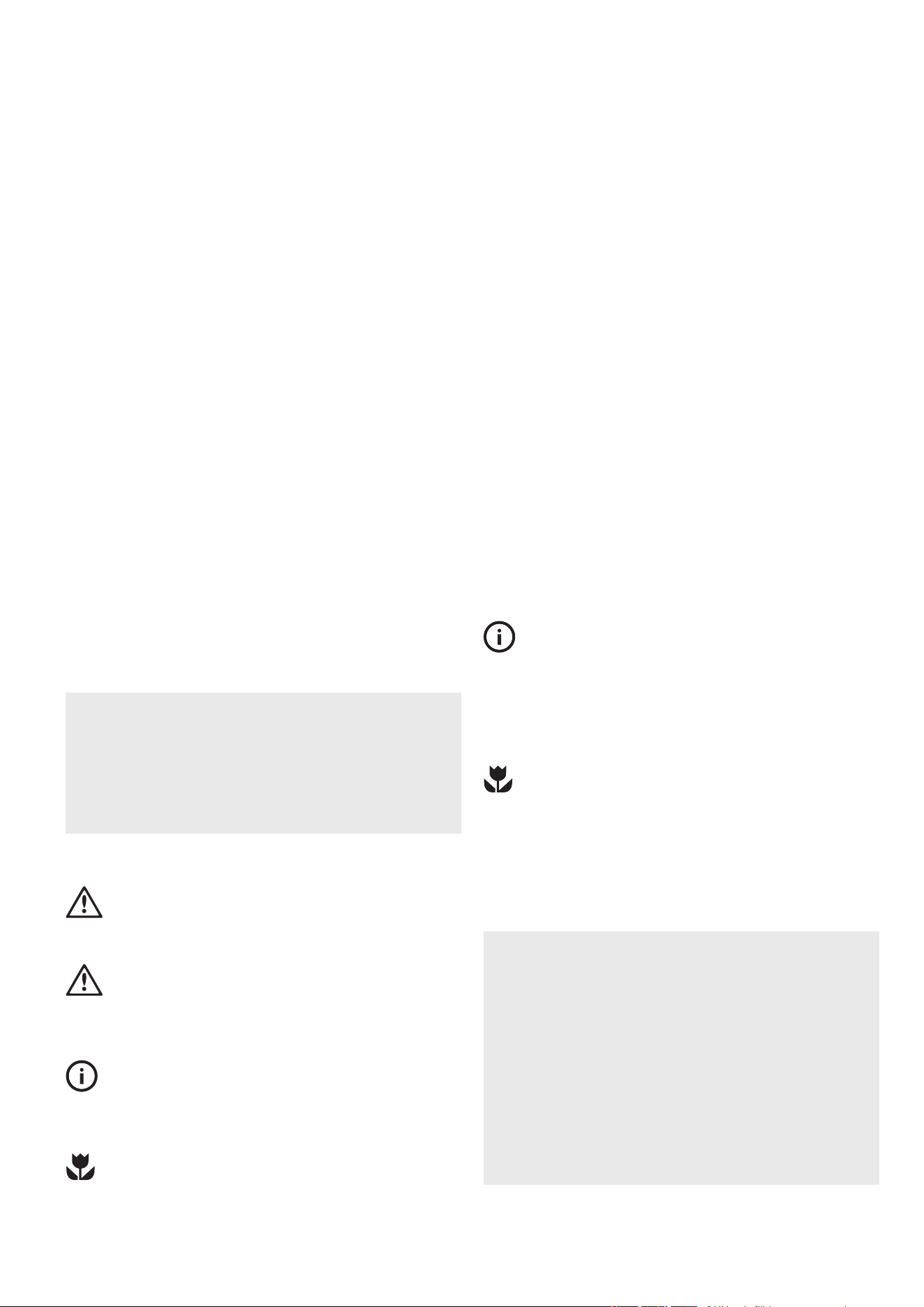
General appliance description
Electric Separate Grill Oven depicted
Control panel
Grill door
(where fitted)
Removable
shelves
Oven door
Removeable inner glass
Kick panel
Front adjustable feet
Rear adjustable feet
Anti-tilt
(Fan forced
model)
Grill element
burner
Splashback
Grill with removable grill
dish side supports grill and
rack (where fitted)
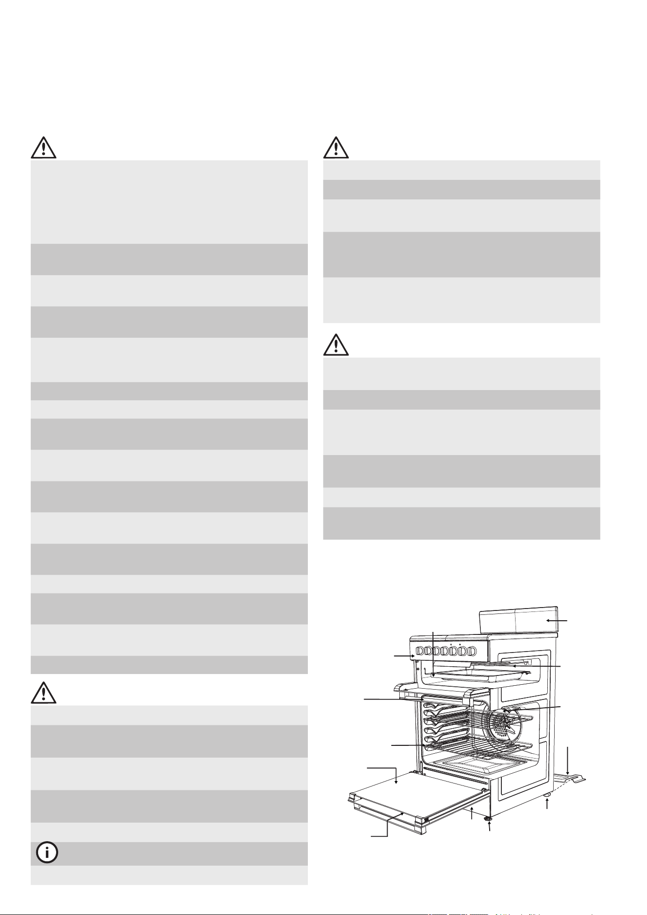
Installation
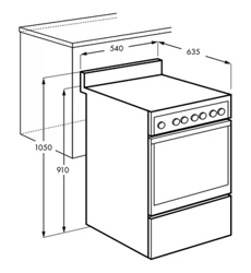
Location
The appliance has been designed to fit a 550mm gap in kitchen
cabinetry or have free space on either side. Ensure the top of the
hotplate is at least 10mm higher than the level of the benchtop.
Electric hob models must not be installed in a corner; they must be
installed at least 100mm from the side wall.
Gas hob models must be installed with a minimum clearance of
100mm to side walls made of unprotected combustible material.
For gas models, refer to section 6.10.1 in AS/NZS 5601.1 for
all relevant clearance.
Clearance to side wall
(see notes above)
Note: The splashback
must be fitted.
Ceramic Tiled Area
1.25m
Electrical service
cord (If fitted)
550mm Minimum
Anti-tilt Plate
540mm
910mm
150mm min.
1050mm
4 Chef 540 Upright Cooker
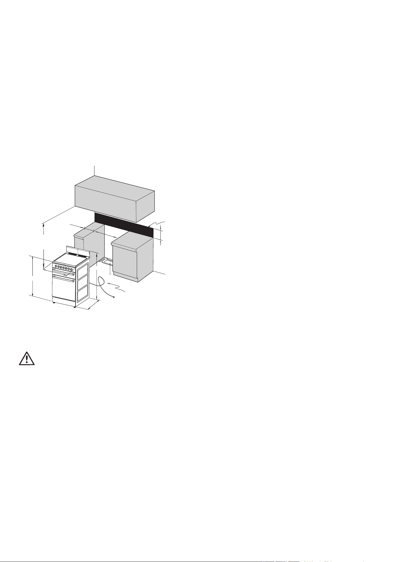
Overhead clearance
(see notes)
For Gas Models
For existing installations where only the gas appliance is being
replaced:
The overhead clearance from the highest part of the highest
burner or the hob of this gas appliance to the range hood shall
be not less than 600mm and not less than 750mm for an
exhaust fan.
Any other downward facing combustible surface less than
600mm above from the highest part of the highest burner of this
gas appliance shall be protected for the full width and depth of
the hob in accordance with AS/NZS 5601.
For all other installations:
The overhead clearance between the supporting surface for the
cooking vessels (top of the trivets) of this gas cooking appliance
and a range hood or exhaust fan (overhead clearance) shall be
not less than 650mm for range hood, and not less than 750mm
for an exhaust fan.
A range hood or exhaust fan shall be installed in accordance
with the range hood or exhaust fan manufacturer`s relevant
instructions.
Any other downward facing combustible surface less than
650mm above the supporting surface for the cooking vessels
shall be protected for the full width and depth of the hob in
accordance with AS/NZS 5601.
Note 1: Removable accessories such as a wok trivet that sits
upon a hob trivet are not taken into account in determination of
the supporting surface for the cooking vessels.
Note 2: Minor elevations in trivets such as a wok trivet formed
into a trivet are not taken into account in determination of the
supporting surface for the cooking vessels.
Note 3: The height of the top of the pan supports (top of the
trivets) with respect to the bench top (built-in) or supporting surface
(elevated) or the floor (freestanding) are detailed separately in
these instructions.
Overhead Clearance
warning
Where the range hood or exhaust fan manufacturer`s relevant
instructions specify a greater clearance, then this greater
clearance shall apply.
Clearance to any overhead surface shall be not less than
450mm.
For Electrical Models
The overhead clearance between the supporting surface of
this appliance and a range hood or exhaust fan shall be not
less than 600mm.
Chef 540 Upright Cooker 5
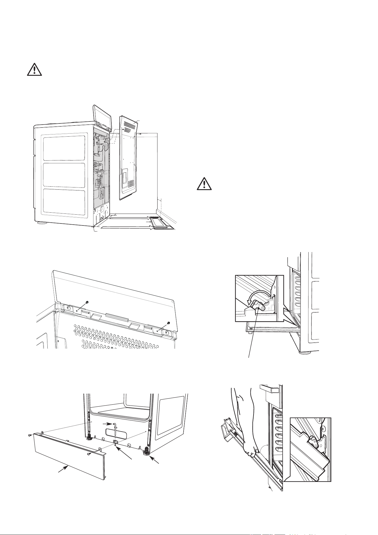
Procedure to remove the door
Stirrup
1.With door fully open, rotate the two stirrups to its rest
position (to engage the stirrups).
Installation
warning
For your safety this cooker is designed to be moved out of
position by a qualified person only.
The unit must be pushed up against the wall on installation.
On gas units check that the gas hose, if used, has not been
kinked during installation.
4. Pull cooker out and drill the bolt hole, using a 6.5mm
masonry or wood drill. Minimum 30mm deep for concrete.
5. Reposition cooker back into place and fit the Stability Bolt
through the slot and into the drilled hole.
6. If the cooker is placed on a base, measures must be taken
to prevent the appliance slipping from the base.
7. Carefully remove any protective plastic film to prevent
damage to the appliance.
2.
3.
Remove screws from kick panel. To remove kick panel lift
kick panel upwards to release the two Location Tabs from
the holes in the bottom of the panel.
Position cooker into the ant-tilt plate and then mark the
position for the Stability Bolt hole on the floor.
Stabilising bolt
Stability
bolt
6.5mm DIA
drilled location
hole.
Front
adjustable
feet
Kick-panel
1.Remove oven door - to be done by qualified personnel only.
(Refer to procedure).
Position anti-tilt plate to the rear wall and 25mm from side of
cupboard. Securely fix anti-tilt plate to the floor with fasteners.
Adjust levelling feet on cooker as required.
warning
In order to avoid accidental tipping of the appliance (for
example, by a child climbing onto the open oven door), the
anti tilt plate and stabilising bolt MUST be installed.
5mm
Clearance
Anti-Tilt Plate
Cooker Width
540mm
Rear Adjustable Foot
25mm to side
of bracket
Rear Cover
Splashback must be fitted to the rear using the two screws
used to fasten the anti-tilt plate and splashback on the rear of
the product.
6 Chef 540 Upright Cooker
Installation
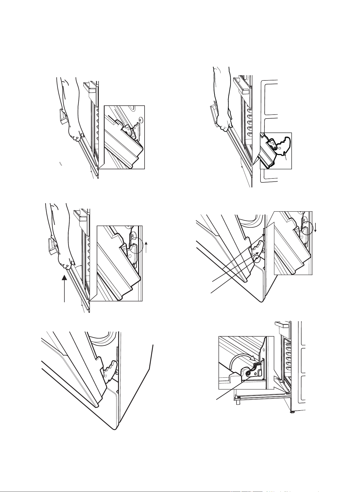
Procedure to assemble the door
Notch
1.Hold door with both hands.
2.Locate both hinges into the frame slots at the same time.
Frame slot
Hinge
Notch
3.Ensure that the location notch drops into frame slot. Care
should be taken not to damage other parts of the cooker.
Stirrup
4.Open door fully and rotate stirrups away from you back to
their original position.
5.Close the door fully.
6.Carefully remove any protective plastic film to prevent
damage to the appliance.
5.Remove the door by lowering gently and pull away from
the frame of the oven. Care should be taken not to damage
kick panel and other parts of the cooker.
4.Lift the door slightly and evenly while continuing to slowly
close the door.
3.Close the door further.
2.Close the door until it stops against the stirrups.
Chef 540 Upright Cooker 7
Electric wiring requirements
The cooker MUST be installed in compliance with:
•Wiring connections in AS/NZS 3000 Wiring Rules.
•Local regulations, municipal building codes and other statutory
regulations.
•Data Plate – Gives information about the rating and is located
behind the bottom of the oven door.
•A functional switch MUST be provided near the appliance in
an accessible position (AS/NZS 3000).
•Wiring MUST be protected against mechanical failure (AS/
NZS 3000).
•Disconnection from the fixed wiring must occur as required by
AS/NZS 3000 wiring rules.
•This range must be connected with cable of 75°C rating
minimum.
•This product has passed the insulation resistance test after
manufacture. If the resistance reading is low at installation, it
is probably caused by moisture from the atmosphere being
absorbed by the elements after the range has been produced.
(pass at 0.01MΩ AS/NZS 3000 Wiring Rules).
•The cooker MUST be properly earthed.
•When connections are made to a multiphase 230/240V
supply, the bridge piece MUST be removed from between the
active connections.
•If the supply cord is damaged, it must be replaced by
the manufacturer, its service agent or similarly qualified
persons in order to avoid a hazard.
•This appliance must be fixed in position or must be
connected to the supply by a supply cord fitted with a
male connector.
Model
Total kW
Total Current
(Amps)
Cable Section
(mm
2
)
Min Temp
(°C)
CFE5328.235.76.0
75
CFE5339.5
41.910.0
75
CFE5368.235.76.0
75
CFE537
10
43.710.0
75
CFE547
9.5
41.910.0
75
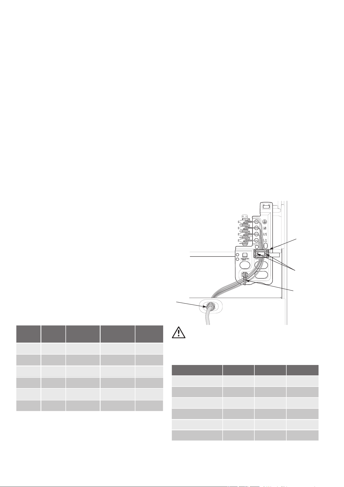
Hard wiring
1.Remove rear panel.
2.Fit wires through hole at bottom centre using the appropriate
gland to protect insulation of wires from the hole edge.
Note that the secondary insulation of the wires will probably
need to be removed to fit through gland. If the conduit to
appliance is required to bend due to rear wall an elbow
may be required to achieve this.
3.Set the length of wiring from the gland to terminal block,
ensuring length is sufficient but not excessive.
4.Make connections to terminals and engage wires into
plastic clip. Cable tie as per diagram and secure plastic
clip with two long screws supplied.
5.Replace rear cover.
Plastic Clip
Plastic
clip screw
securing
points
Cable tie
Gland
warning
Ensure wires cannot contact hot element ends or sharp edges.
Rated power input
ModelTotal kWA1 kWA2 kW
CFE5328.22.26.0
CFE5339.5
3.66.0
CFE5368.22.26.0
CFE537
10
4.06.0
CFE547
9.5
4.05.6
Installation
CFE535
9.5
41.910.0
75
CFE5356.03.6
9.5
8 Chef 540 Upright Cooker
Gas requirements
This appliance must be installed by an authorised person,
according to all codes and regulations of:
•AS/NZS 5601 series (particular attention to specific
requirements for domestic gas cooking appliances)
•Local gas fitting regulations, municipal building codes and
other statutory regulations.
The cookers are made for Natural Gas. Conversion to Propane
(Australia) or ULPG (NZ) is possible. The cooker is supplied with
a kit for conversion to Propane (Australia only). Refer to Gas
Conversion Instructions on Page 11 in this user manual.If the
cooker is required to use ULPG (NZ only), a conversion kit can
be obtained by contacting the Customer Care Centre for details.
Before installation, check that the cooker is configured for the
gas supply.
The following table shows the supply and operating pressures
for various supplies.
Gas typeNatural gasUniversal LPGPropane
Supply pressure at
inlet to appliance
regulator (if fitted)
1.13 (kPa)
Minimum
2.75* (kPa)2.75* (kPa)
Operating pressure
at appliance test
point
1.00 (kPa)2.75 (kPa)2.75 (kPa)
* If the regulator is placed upstream of the cooker inlet, as
is normal for cookers operating on LPG, then the supply
pressure and operating pressure are the same. The injector
sizes for each burner are shown in the Gas Conversion
Instructions on Page 16.
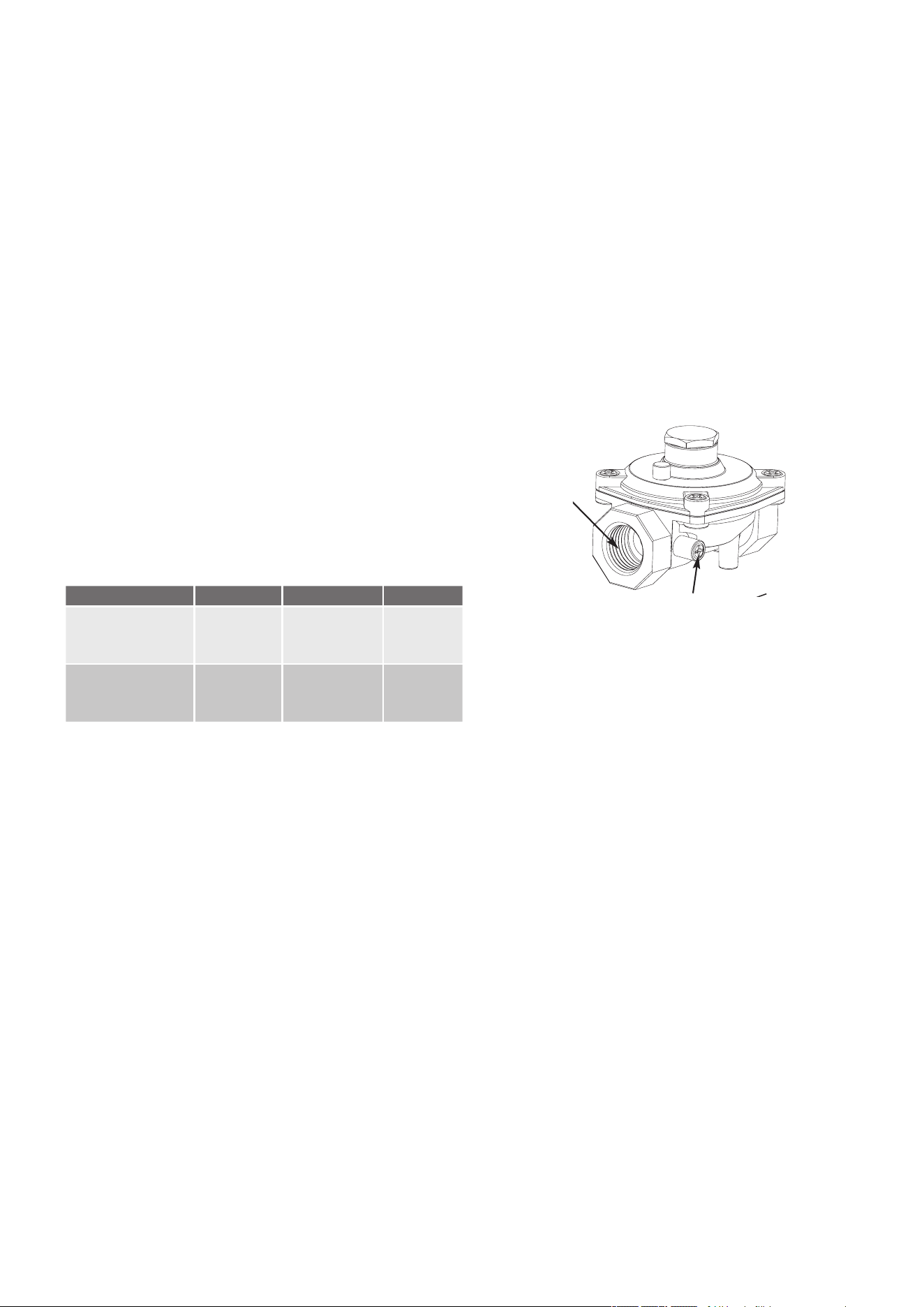
Fitting of Gas Regulator
•The appliance regulator MUST be orientated so that the
pressure nipple is accessible
•The arrow showing the direction of flow MUST be pointed
correctly
•The regulator has a ½” BSP internal thread at the inlet and
outlet.
1/2”B SP
Internal Thread
Pressure test point
Gas Regulator
Use AS/NZS 5601 to ensure adequate gas supply
Installation
Chef 540 Upright Cooker 9
Installation
Checking pipe size
To work out a suitable pipe size for connection use the
information in this table.
Gas Consumption (MJ/h)
Model Natural gasUniversal LPGPropane
CFG501
58.145.756.5
CFG5044736.747.5
CFG5054736.747.5
CFG51360.248.258.3
CFG51749.139.249.3
Wiring connection for gas cooker
To allow for disconnection of the appliance after installation,
the plug must be accessible after installation, or a functional switch
must be provided near the appliance in an accessible position.
If the supply cord is damaged, it must be replaced by the
manufacturer, its service agent or similarly qualified persons in
order to avoid a hazard.
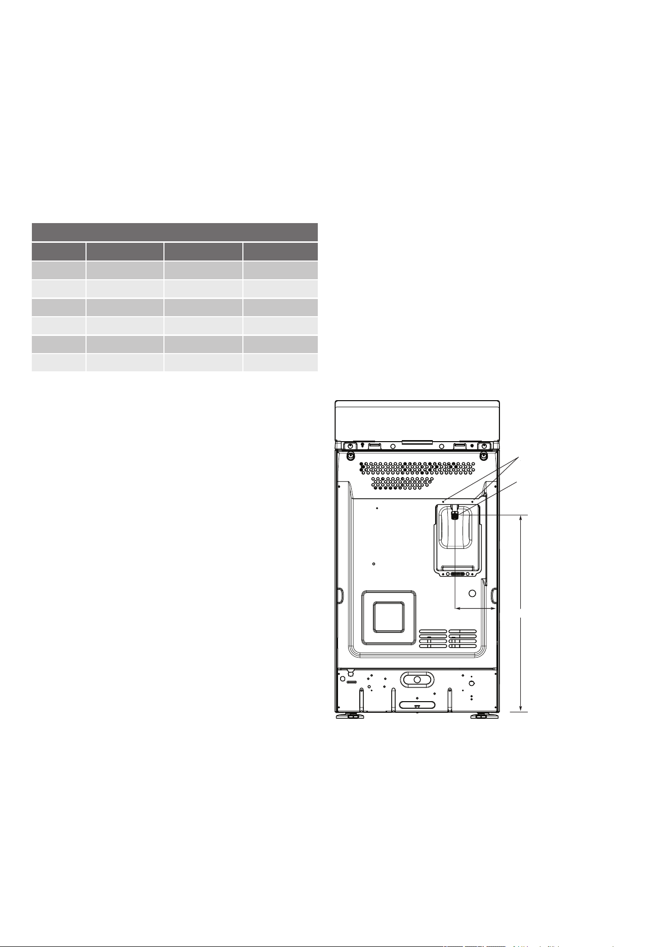
Gas connection
Read these points before connecting to the gas supply:
•The cooker inlet connection point has a ½” BSP
externalthread. See Diagram below
•A gas regulator is supplied
•It is recommended to fit the regulator to the
applianceconnection point, then fit either hard piping or a
high levelflexible connection (AS/NZS 5601.1) which is
then attached to the consumer hard piping
•Ensure installation allows withdrawal of appliance.
Restraining Device
Anchor Points
Gas
Connection Point
150mm
650mm
Restraining Device
Anchor Points
Gas
Connection Point
CFG50358.145.756.5
10 Chef 540 Upright Cooker
Conversion to SNG or ULPG (NZ only)
Please contact Electrolux Customer Service for
conversion kit and instructions.
Testing the gas cooker
warning
You MUST test the cooker after installation, before you hand it
over to the customer.
You MUST have a manometer and a connecting tube.
Checking the gas supply
1.Check the manometer zero point is correct.
2.Connect the manometer to the cooker pressure test point. This
is located on the regulator.
3.Turn on the gas supply and the electricity (if applicable) and
try to ignite the gas. Note: It will take additional time to light
the gas for the first time, as air needs to be purged from the
pipes.
4.Check the operating pressure for the particular gas type
(see'Gas Type' table).
Regulators are supplied pre-adjusted and configured by the
component maker for use with Natural Gas. The appliance
installer is not required to make an adjustment to obtain the
correct outlet pressure setting. An arrow on the base of the
regulator indicates the direction of the gas flow when the
inlet and outlet of the regulator are orientated correctly.
5.When the regulator has been fitted check for leaks from the
connections with soapy water.
Checking regulator function
With the appliance operating, check the outlet pressure:
1.When all the burners of the appliance are operating at
maximum.
2.When the smallest burner of the appliance is operating at
minimum, Under these conditions the outlet pressure should
not vary from nominal operating pressure of 1.0kPa (for
Natural Gas) or 2.75kPa (for Propane and ULPG) by more
than ± 20% (ie ±0.20kPa for Natural Gas).
If the regulator appears to not be performing satisfactorily
then check the following points:
1.If the outlet pressure is consistently too low then.
•the inlet pressure may be too low and adjustment of an
upstream regulator may be needed, or
•an upstream regulator or valve with insufficient
flowcapacity may be present in the gas supply line. It may
benecessary to repeat the checks whilst measuring both
theinlet and outlet pressure to determine if the inlet pressure
is1.13 - 5kPa for NG, 2.75 - 7 kPa for Propane and
ULPG.
2.Check that the regulator has been fitted to the gas supply
line in the correct orientation.
3.Replace the regulator if it fails to perform after the checks.
Testing cooker features
•Observe the flame appearance on each burner. If it is
smaller or larger than expected, then the injector size
needs checking
•If the flame is unsatisfactory, then refer to the Electrolux
Technical Publications and correct the fault if possible
•When maximum flame appearance is correct, check the turn
down setting on each burner. If incorrect, proceed as follows:
warning
1.Disconnect electric power.
2.Remove the control panel and adjust the bypass screw
mounted on the body of each hotplate control cock.
3.Check the ignition on all burners both separately and in
combination.
4.Check the operation of the electrical components, if
applicable.
5.When operating correctly, show customer how to use the
cooker.
6.If not operating correctly, advise the customer to ring
Electrolux service. Place a warning sign on cooker or if
dangerous, disconnect cooker.
Installation
Chef 540 Upright Cooker 11
Conversion to LP/Propane Gas
For conversion to Universal LPG/propane gas types, all gas
injectors need to be changed, all gas valves are adjusted,
the gas regulator is converted, and the gas grill burner
aeration shutter is changed where the gas grill is provided.
If the conversion kit is not available, please reach out to our
Customer Care team at 131349 (if you are in Australia) or
0800436245 (if you are in New Zealand) or by email.
After converting the appliance, attach the ULPG or Propane
sticker to the cooker, near the gas supply inlet. Cover the
Natural Gas label that is factory fitted.
Important: The conversion must be performed by a
qualified service technician in accordance with the kit
instructions and all local codes and requirements. Failure to
follow instructions could result in serious injury or property
damage.
WARNING
Failure to make the appropriate conversion can result in
serious personal injury and property damage.
Note: Always perform a gas leak test after converting the
appliance.
Gas Hob Conversion
Tools required:
•7mm hex socket screwdriver or 7mm nut runner.
•Small flat-blade screwdriver.
1.Remove trivets/pan supports, burner crown, and top
caps from burner bases.
2.Using a 7mm socket, remove Natural Gas injectors.
3.Using the Injector table and hob layout diagram, select
the correct gas injector for each burner and intended gas
type.
4.Using a 7mm socket, screw in gas injectors. Set injectors
in place firmly but not with excessive torque.
5.Reinstate trivets/pan supports, burner crown, and top
caps ensuring that these components are sitting correctly
on their respective lower parts.
6.If Gas Separate Grill is provided, please go to “Gas
Separate Grill Conversion”, otherwise proceed to the
next step.
7.Remove all control knobs on the front of the cooker by
gripping each knob behind its skirt and pulling away
from the control panel.
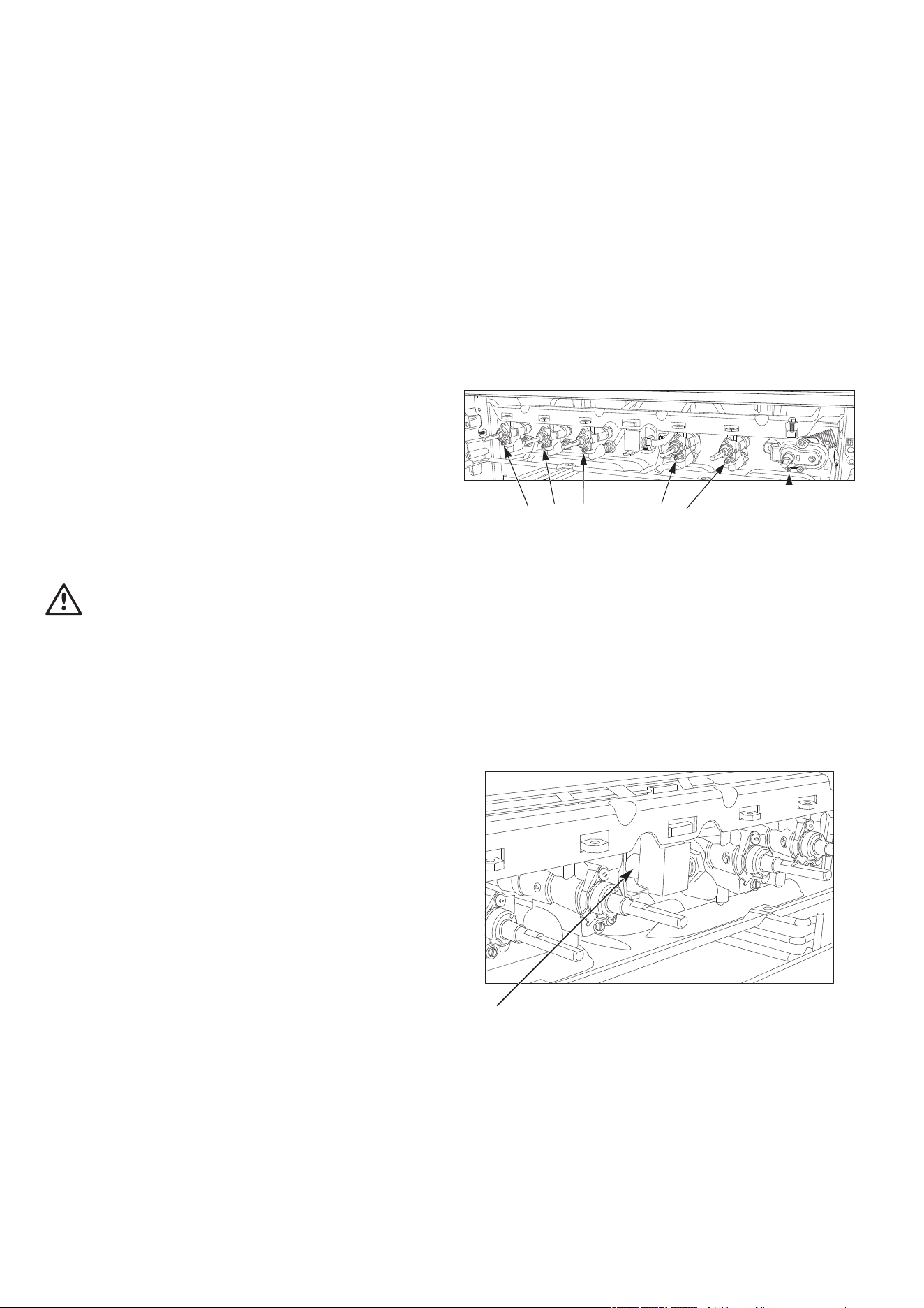
8.Locate the recessed turndown adjustment screw in each
gas valve, insert the screwdriver, and turn the adjustment
screw clockwise until the screw stops.
Note: If a Gas Oven is present its control can be
adjusted the same way. If access to adjustment screws
is not clear, see “Gas Separate Grill Conversion”
instructions on how to remove the control panel.
22300
M
Adjustment screws at each gas valve
for hob and gas grill where fitted
Adjustment screw for oven
thermostat where fitted
Note: If the thermostat body is brass (dull yellow colour),
replace the existing adjustment screw with the LPG adjustment
screw supplied in the conversion kit and turn the screw
clockwise until the screw stops. If the thermostat body is all
aluminium (silvery white colour), turn the existing adjustment
screw clockwise until the screw stops.
9.Install control knobs (with separate skirts where used) by
pushing them on fully.
Gas Separate Grill Conversion (Where used)
Gas conversion instructions
Injector on the injection block
Tools required:
•7mm open-ended or ring spanner.
•#2 Phillips head screwdriver.
12 Chef 540 Upright Cooker
1.Warning: Risk of electric shock. Ensure the
cooker is NOT plugged into a power point before
proceeding.
2.Remove all control knobs on the front of the cooker by
gripping each knob behind its skirt and pulling away
from the control panel if not already done as part of the
Gas Hob conversion.
3.Remove the control panel by removing the 2 screws
behind the grill door below the Control Panel. Rest the
control panel on the open grill door being careful not to
stretch or damage the wiring.
4.Warning: Risk of laceration. The now exposed
front edge and other edges of the grill compartment
panel can have sharp edges. Wear appropriate gloves.
5.Remove the grill burner gas injector using the 7mm
spanner from its holder in front of the aeration shutter. To
loosen the injector, rotate the spanner in a clockwise
direction as you are working from behind it!
6.Select the correct gas injector for the grill burner and the
intended gas type and replace the grill burner gas
injector. Set the injector in place firmly but not with
excessive torque.
7.Locate the recessed turndown adjustment screw in each
gas valve, insert the screwdriver, and turn the adjustment
screw clockwise until the screw stops. Note: All gas
valves for the Gas Hob, Gas Oven, and Gas Separate
Grill need to be adjusted the same way.
8.Replace the control panel being careful to ensure any
wires do not get trapped between the grill compartment
panel and the control panel as per the reverse of step 3.
9.Install control knobs (with skirts where used) by pushing
them on fully.
•7mm open-ended or ring spanner or 7mm hex socket
screwdriver or nut runner.
•#2 Phillips head screwdriver.
1.Warning: Risk of electric shock. Ensure the
cooker is NOT plugged into a power point before
proceeding.
2.Remove the plastic cover behind the gas connection point
by unscrewing 2x Phillips screws).
3.Warning: Risk of laceration. The rear cover
and internal components can have sharp edges. Wear
appropriate gloves and long sleeve & leg clothes.
4.Remove the rear panel by unscrewing 2 (or 4 where
used) Phillips screws.
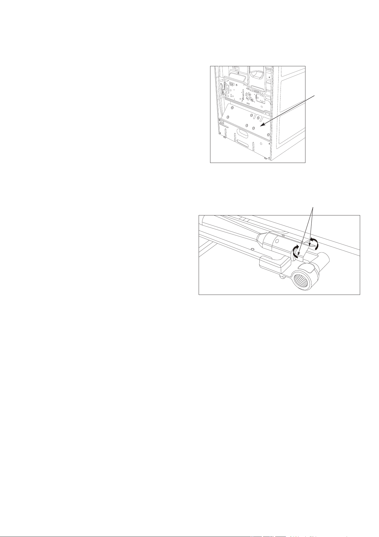
5.Inside the lower back of the cooker, remove the lower
internal baffle plate (where fitted).
Gas conversion instructions
Lower internal
baffle plate
6.Remove the gas injector holder from the burner by
bending up the 2 metal tabs at the end of the burner
holding the gas injector, then slide the injector holder out
of the burner body.
Metal tabs of the
burner
7.Remove the oven burner gas injector from its holder using
the 7mm spanner or socket or nut runner.
8.Select the correct gas injector for the oven burner and
the intended gas type and replace the oven burner
gas injector. Set the injector in place firmly but not with
excessive torque.
9.Slide the gas injector holder back into the burner and
bend down the 2 metal tabs to ensure that the injector
holder cannot slide out of the burner body.
10. Install the internal baffle (where used), rear cover, and
plastic cover behind the gas connection as per the
reverse of steps 1 to 4.
Note: Adjustment of the turndown of the Gas Oven valve
(thermostat) should have been done as part of the Gas Hob
Conversion.
Gas Oven - Freestanding Cookers (Where used)
Tools required:

Chef 540 Upright Cooker 13
Gas Oven - Elevated Cookers
Tools required:
•7mm open-ended or ring spanner or 7mm hex socket
screwdriver or nut runner.
•#2 Phillips head screwdriver.
1.Warning: Risk of electric shock. Ensure the
cooker is NOT plugged into a power point before
proceeding.
2.Remove the rear bridging plate between the oven and
hob at the rear of the cooker.
3.Warning: Risk of laceration. The rear cover
and internal components can have sharp edges. Wear
appropriate gloves and long sleeve & leg clothes.
4.Remove the oven rear panel by unscrewing 2 (or 4
where used) Phillips screws.
5.Remove the gas injector holder from the burner by
bending up the 2 metal tabs at the end of the burner
holding the gas injector, then slide the injector holder out
of the burner body. Refer to the figure above.
6.Remove the oven burner gas injector from its holder using
the 7mm spanner or socket or nut runner.
7.Select the correct gas injector for the oven burner and
the intended gas type and replace the oven burner
gas injector. Set the injector in place firmly but not with
excessive torque.
8.Slide the gas injector holder back into the burner and
bend down the 2 metal tabs to ensure that the injector
holder cannot slide out of the burner body.
9.Install the rear cover and bridging plate as per the
reverse of steps 1 to 3. Note: Adjustment of the turndown
of the Gas Oven valve (thermostat) should have been
done as part of the Gas Hob Conversion.
Gas conversion instructions
14 Chef 540 Upright Cooker
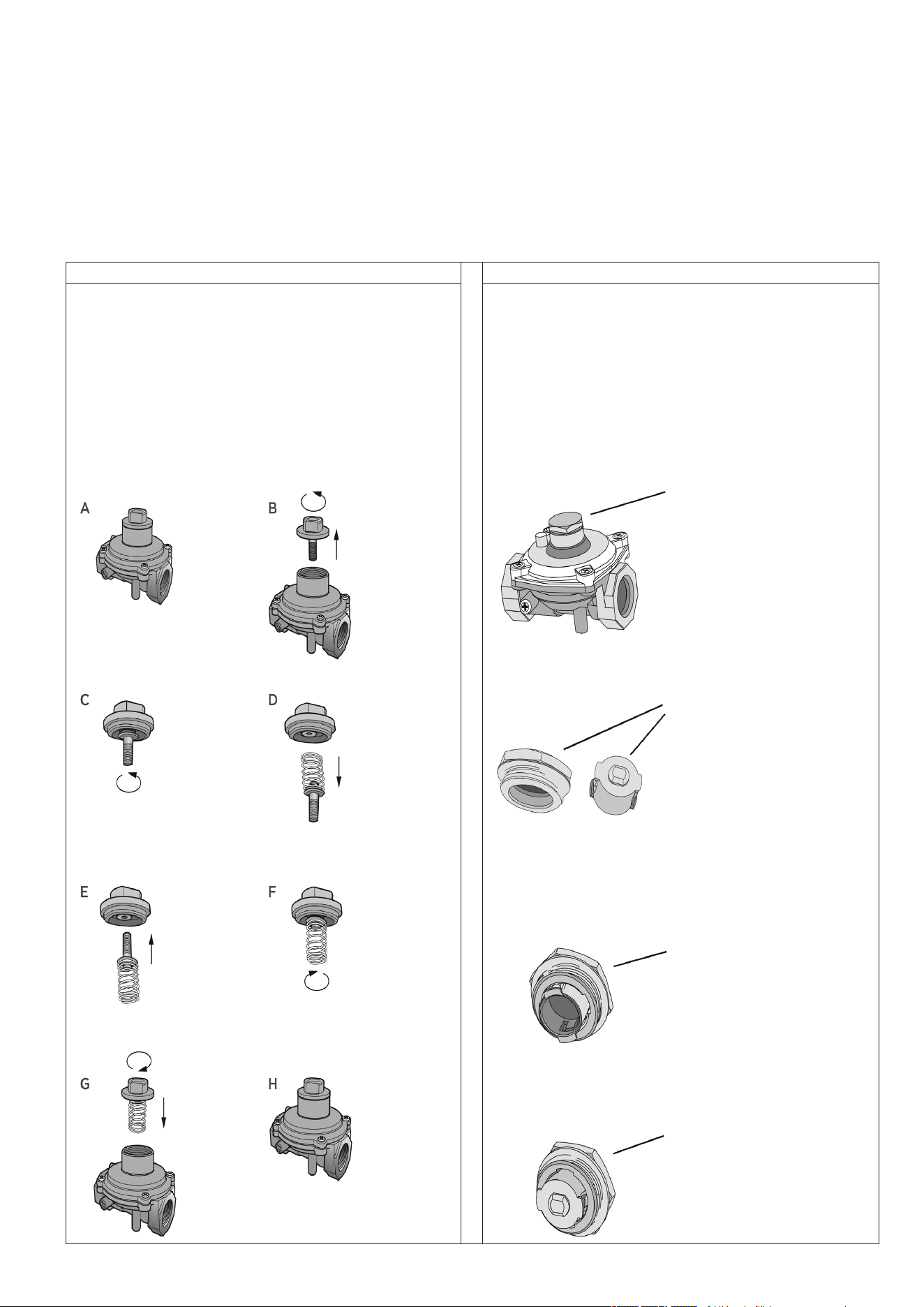
Gas Regulator Conversion
Chant RegulatorDong Yang Regulator
1.Unscrew the top hat nut from the regulator. The top hat
nut and control pressure spring assembly will disengage
as an assembly. See figures A&B.
2.Unscrew the threaded pin from top hat. See figures
C&D.
3.Turn over threaded pin, so spring is free and screw pin
back into the top hat until firm. See figures E&F.
4.Screw the top hat nut assembly back into the regulator
ensuring that it is fully screwed down. See figures G&H.
The regulator is now set for connection to LPG.
Top hat nut assembly,
fully screwed down
Turn top hat nut
anti-clockwise
and remove
Configuration for
Natural Gas
Configuration for LPG
1.Unscrew the hex nut from the regulator. The hex nut,
brass washer and nylon insert will disengage as an
assembly. See Fig. 1.
2.Unclip the nylon insert from the nut assembly by rotating
the insert ¼turn, and pulling it free. See Fig. 2.
3.Turn over the insert, and clip back into position. See
Fig. 3&4.
4.Screw the hex nut assembly back into the regulator
ensuring that it is fully screwed down. The regulator is
now set for connection to LPG.
Hex nut assembly,
fully screwed down
Hex nut assembly,
removed from regulator
and insert disassembled
Insert oriented for Natural
Gas operation
Insert oriented for LPG
operation
Fig. 1
Fig. 2
Fig. 3
Fig. 4
Gas conversion instructions

Chef 540 Upright Cooker 15
Commissioning Gas Type Conversion
Tools required:
•A manometer capable of reading from 0 to at least
3.0kPa.
1.Remove the Test Point (TP) from the appliance Gas
Regulator and connect a manometer capable of reading
from 0 to at least 3.0kPa.
2.Turn on the gas supply to the appliance and test for
leaks.
Gas Hob Commissioning
1.Turn on a Gas Hob burner to high and hold the gas valve
control knob in. At the same time use the inbuilt igniter
(240v powered models) or a gas match applied to that
burner to provide an ignition source.
2.Once the burner is lit and after 5s release the valve knob
and observe for the following:
a.Flames have traveled to all burner ports promptly.
b.Burner stays alight once gas valve knob is released.
c.Burner flames are almost entirely blue. Some light
yellow within the flame may be present but there
should be no yellow at the tip at the outer end of the
flame.
d.The TP pressure as indicated by the manometer
should be between 2.2kPa and 3.3kPa.
(2.75kPa +/- 20%)
e.See "Fault Finding" if any of these requirements are
not met.
3.Rapidly move the gas valve of the lit burner from high to
low and back again a few times. The burner should stay
alight. If the burner does not stay alight, adjust the
turndown for that burner at the gas valve slightly counter-
clockwise to increase the gas rate at minimum turndown.
Refer to Gas Hob Conversion instructions.
4.Shut off the burner and repeat for all other Gas Hob
Burners.
5.Light all Gas Hob Burners and repeat step 2.
Gas Separate Grill Commissioning (Where used)
1.Turn on the Gas Grill burner to high, press in, and hold
the gas valve control knob in. At the same time use the
inbuilt igniter to provide an ignition source.
2.Once the burner is lit observe the following:
a.Flames travel to all burner ports promptly.
b.Burner stays alight once gas valve knob is released.
c.Burner flames are almost entirely blue. Some light
yellow within the flame may be present but there
should be no yellow at the tip at the outer end of the
flame.
d.The TP pressure as indicated by the manometer
should be between 2.2kPa and 3.3kPa.
(2.75kPa+/- 20%)
e.See "Fault Finding" if any of these requirements are
not met.
3.Rapidly move the gas valve of the lit burner from high to
low and back again a few times. The burner should stay
alight. If the burner does not stay alight, adjust the
turndown for that burner at the gas valve slightly counter-
clockwise to increase the gas rate at minimum turndown.
Refer to Gas Hob Conversion instructions.
Gas Oven Commissioning (Where used)
1.Turn on the Gas Oven Thermostat to 120°C, press in,
and hold the gas valve control knob in. At the same time
use the inbuilt igniter to provide an ignition source.
2.Once the burner is lit observe the following:
a.Flames travel to all burner ports promptly.
b.Burner stays alight once gas thermostat knob is
released.
c.Burner flames are almost entirely blue. Some light
yellow within the flame may be present but there
should be no yellow at the tip at the outer end of the
flame.
d.The TP pressure as indicated by the manometer
should be between 2.2kPa and 3.3kPa.
(2.75kPa+/- 20%)
e.See "Fault Finding" if any of these requirements are
not met.
Gas conversion instructions
16 Chef 540 Upright Cooker
3.Close the door and wait for the thermostat to operate
and turn the burner down to maintain 120°C. The
burner should stay alight. If the burner does not stay
alight, adjust the turndown for the burner at the gas valve
slightly counterclockwise. Refer to Gas Hob Conversion
instructions on how to locate the adjustment screw.
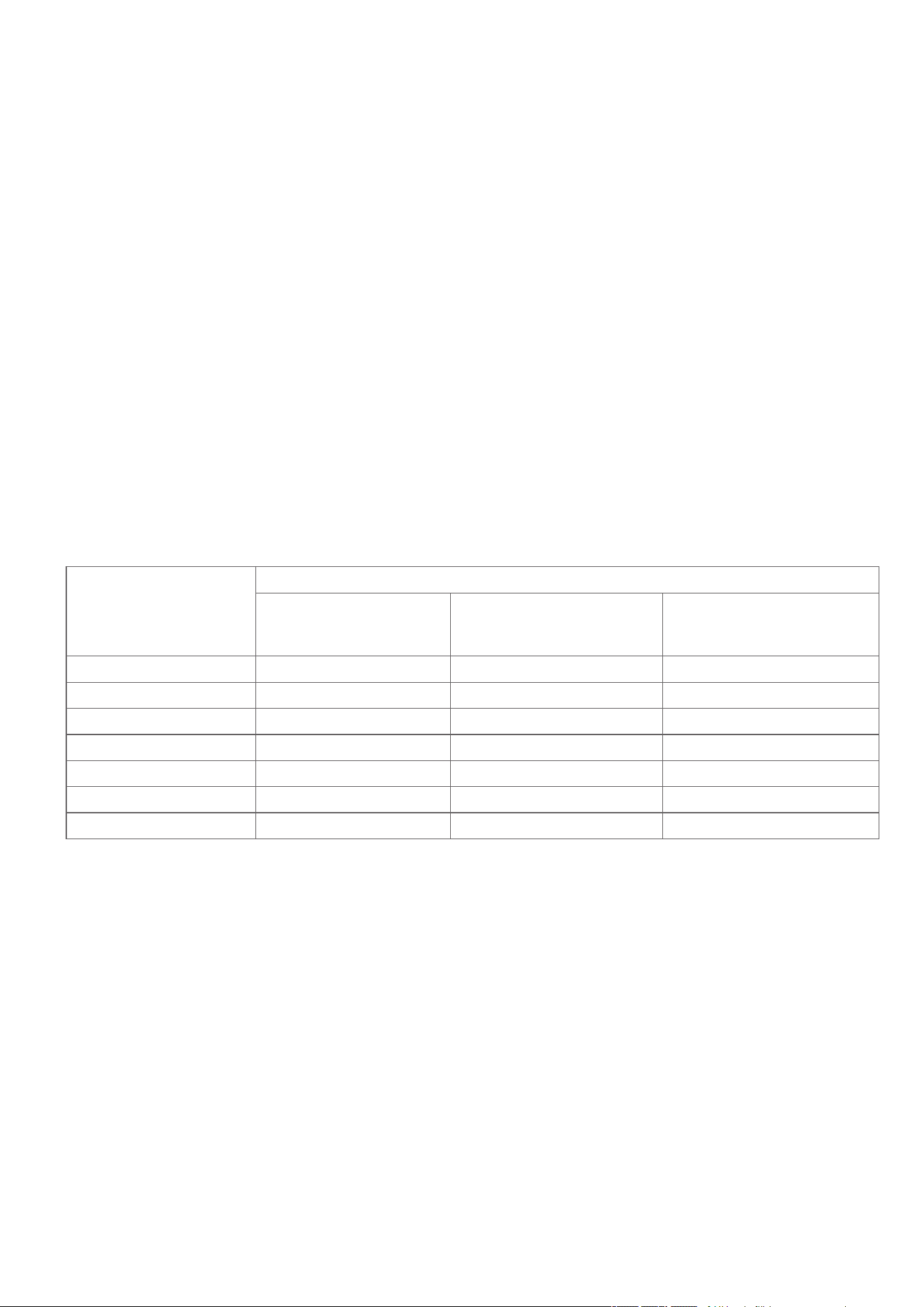
Table for injector sizes
The following table shows the injector sizes for each burner.
Burner
Injector Size (mm)
Natural gas
(Nominal test point pressure:
1.00kPa)
Propane – For Australia only
(Nominal test point pressure:
2.75kPa)
ULPG - For NZ o
nly
(Nominal test poi
nt pressure:
2.75kPa)
Intense heat wok burner1.751.001.00
High heat burner1.600.950.90
Medium heat burner1.350.820.70
Low heat burner1.000.620.55
Grill1.500.820.82
Oven1.600.950.82
Gas conversion instructions
Oven - bypass screw*0.730.450.45
*See instructions on page 11.

Chef 540 Upright Cooker 17
Fault Finding
PROBLEMPOSSIBLE CAUSESWHAT TO DO
Burner will not lightGas not turned onCheck supply
Air not purged from gas pipesPurge gas pipe to appliances
Keep gas valve open for a longer time while keeping
ignition source present at that burner
Ignition source not operatingCheck appliance is plugged in and 240V power
supply is available
Check spark at burner (Gas Oven and Gas Separate
Grill only with piezo ignition)
Attempt to light burner with gas match to confirm
presence of fuel gas
Burner flames are
very big and/or very
yellow
Incorrect Gas Injector sizeCheck injector against requirement in gas injector
table for the required gas type
Hob burner crown and/or cap not correctly
set in place
Check that hob burner crown is seated in base and
cap is seated on the burner crown
Gas Oven injector holder not set in place or
pipe bent at oven injector holder
Check oven injector holder is fully in the receptacle
of the oven burner, adjust pipe to burner assembly to
give blue flame
Incorrect gas pressureCheck Gas Regulator outlet pressure at Test Point on
Gas Regulator
Check Gas Regulator inlet supply pressure
Check that Gas Regulator conversion instructions have
been followed correctly
Burner flames are
small when gas valve
on high
Incorrect Gas Injector sizeCheck injector against requirement in gas injector
table for the required gas type
Incorrect gas pressureCheck Gas Regulator outlet pressure at Test Point on
Gas Regulator
Check Gas Regulator inlet supply pressure
Check that Gas Regulator conversion instructions have
been followed correctly
Burner flames are
uneven - Gas Hob
Burners
Hob burner crown and/or cap not correctly
set in place
Check that hob burner crown is seated in base and
cap is seated on the burner crown
Gas injector not screwed in correctlyCheck that Gas Injector orifice is pointing straight up
Burner flames
are uneven - Gas
Separate Grill
Gas injector not screwed in correctly Check that Gas Injector orifice is pointing straight up
Burner flames are
uneven - Gas Oven
Burner flames on the left is higher than the
right side flames as looking at the oven
This is normal. No action required
Gas injector not screwed in correctly or Gas
injector holder not fitted correctly
Check that Gas Injector is fitted correctly, and injector
assembly is inserted into burner
No ignition sparkWires disconnected at the back of piezo
ignitor (piezo ignition only)
Remove control panel and check wiring
Wires disconnected at the back of switch
(240V)
Turn off and disconnect from 240V outlet, then
remove control panel to check no wires have become
disconnected
No 240V powerCheck whether power supply is available and turn on
Gas conversion instructions
18 Chef 540 Upright Cooker
Operating for the first time
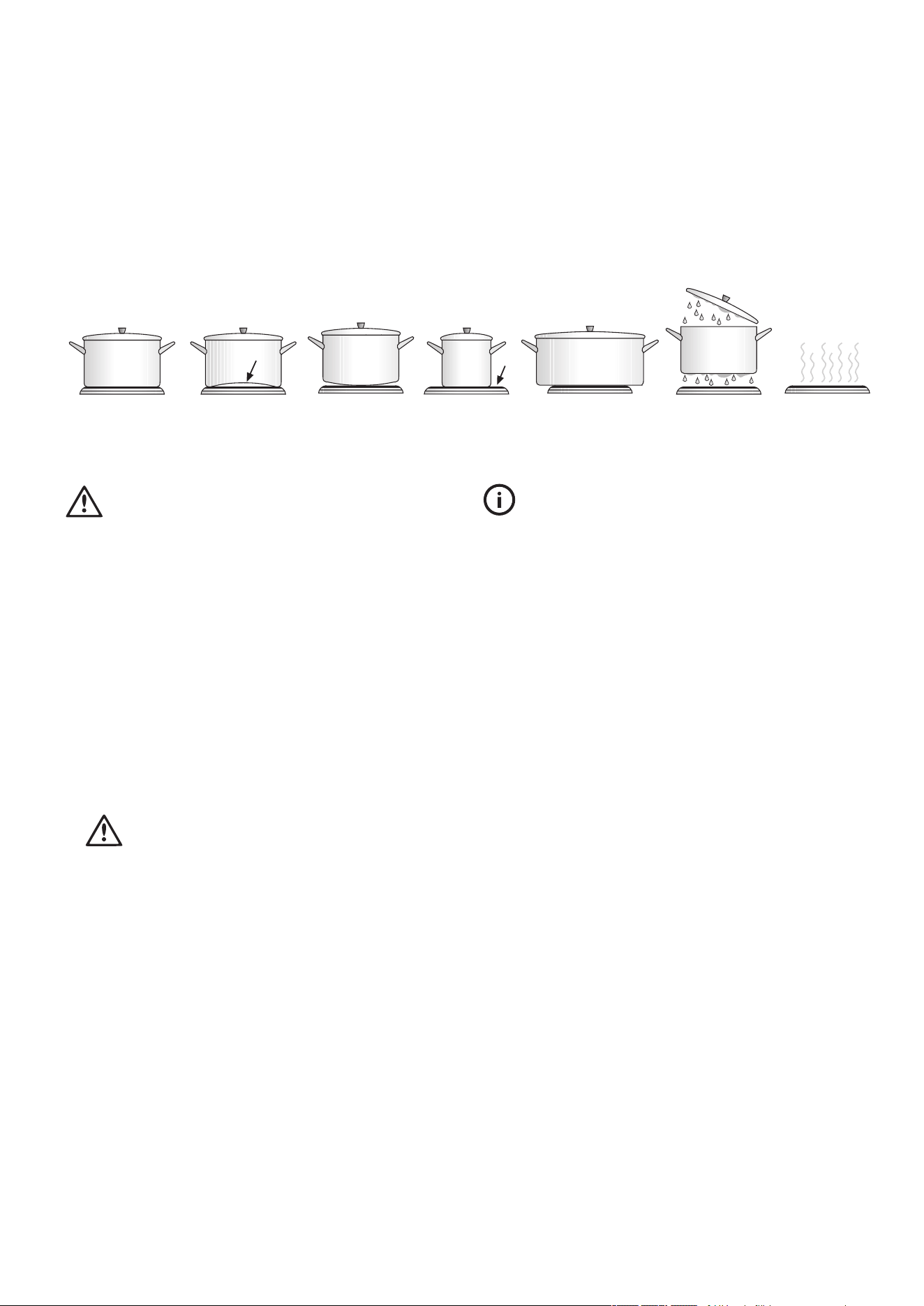
Choosing utensils for gas and electric hotplates
Refer to diagram below
GOOD BAD
(recessed base)
BAD
(convex base)
BAD
(undersize)
BAD
(oversize)
BAD
(moisture on hotplate)
BAD
(no utensil)
Installation and service warning
•Only an authorised person must install and service this
appliance (Certificate of Compliance to be retained)
•In order to avoid tipping of appliance the anti-tilt plate
MUST be installed
•Appliances requiring connection to 230 – 240V MUST
be earthed
•An authorised person should inspect this appliance every
5 years
•This appliance must NOT be installed on a base, box or
in a closed cupboard
•If the electrical supply cord is damaged, a qualified
person MUST replace the cord to avoid a hazard or void
your warranty
•
Surrounding kitchen cabinets MUST WITHSTAND
85°C
•In order to avoid a hazard the installation instructions
MUST be followed.
Before operating first time
1.Read all the Warning and Safety information.
2.Remove all internal boxes and bags from oven.
3.Clean out the oven interior with detergent and hot water
and polish with a soft cloth. DO NOT close oven door until
the oven is completely dry.
4.New appliances can have an odour during first operation.
It is recommended to ‘run in’ the oven before you cook.
Run the oven at 180°C for 2 – 4 hours and ensure that the
room is well ventilated.
5.If your appliance is fitted with solid hotplates, turn heat
setting to high for 3 minutes to fully harden the hotplate
coating.
Chef 540 Upright Cooker 19
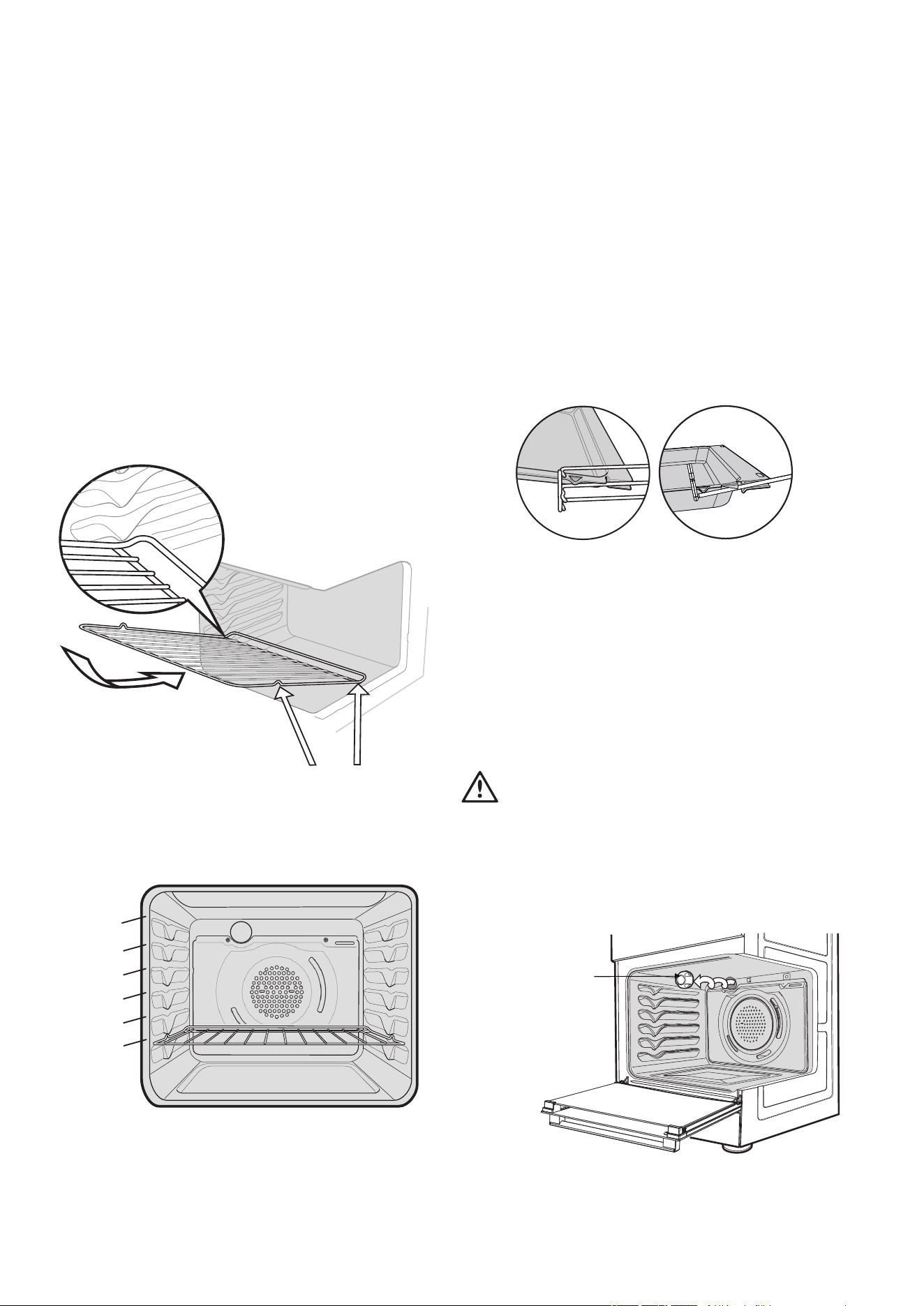
Installing your oven accessories
Fitting oven shelves
1.Ensure shelf orientation is correct (refer to diagram below).
2.Slide oven shelves onto oven supports (side runners) at an
angle until raised back of shelf is past the stop on oven
supports (side runners).
3.Lower front of shelf and push in until stop is reached.
4.To remove oven shelves, withdraw to the stop and raise the
front of shelf to clear the stop.
Note the orietaton of the
side and rear features
Oven shelf location
1
2
3
4
5
Not a shelf
position
NOTE: the top ledge is not a shelf position.
There are no stops for shelf withdrawal.
Fitting the grill dish
Separate Grill: Ensure rear of the dish is engaged with the
side support before sliding backwards. To remove, simply
pull forwards and upwards.
To ensure proper grill operation, slide the grill dish fully
rearward to the stop.
To remove, simply pull forwards and upwards.
Engagement
of rear of
dish
NOTE: Models CFG505 and CFG517 contains single position
side racks.
Grill in Oven: see Fitting Oven Shelves
The grill dish with wire insert can be used in any of the two upper
height positions (shelf positions 4 and 5) between the runners.
NOTE: You must remove the grill dish when baking in the oven.
Replacing the oven light
warning
Ensure the appliance is switched off at power supply (not just
the control knobs) before replacing the light globe to avoid
possibility of electric shock.
Turn light anti-clockwise
to remove it for globe
20 Chef 540 Upright Cooker
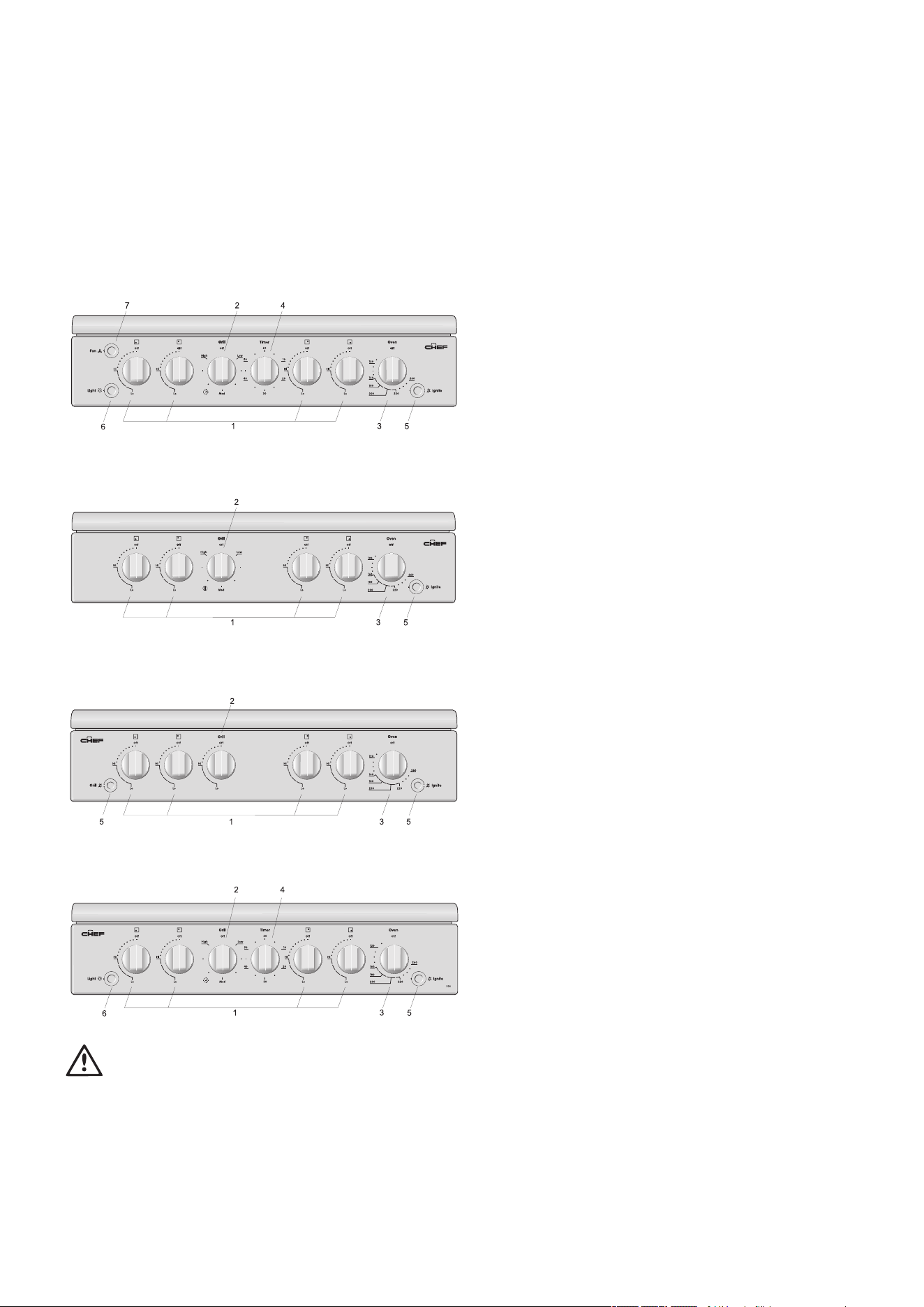
Using the gas cooker
Gas oven features and descriptions
CFG505
CFG501 / CFG503 / CFG513
CFG504
warning
For CFG504 models only, do not operate the gas oven and
grill together.
1. Burner Control Knob – sets burner temperature.
2. Grill Control Knob – sets grilling temperature.
3. Oven Control Knob – sets oven temperature.
4. Timer 60 Minute (where fitted) – sets reminder time. When
timer returns to zero, timer gives a short ring.
NOTE: for any time below 15 minutes, turn knob past
15minutes, then back to required time setting.
5. Manual Grill or Oven Igniter or Hotplates
– ignitesgrillburner, oven burner or hotplates when
appropriate control knobs are set.
6. Light Switch (where fitted) – turns oven light on/off.
7. Fan Switch – turns oven fan on/off.
Gas oven conventional baking
The heat comes from the bottom oven burner. The temperature at
the centre of oven is the same temperature set on the control
knob. When oven is used on this mode, shelf position is
important, (refer to ‘Oven Guide’). As hot air naturally rises,
the upper half of the oven will be approximately 10°C higher
and the lower half approximately 10°C cooler than the set
temperature.
For best results from your gas oven use dark coloured trays
and baking dishes on a single shelf. Refer to ‘General Hints
and Tips’ section for more information.
Gas oven fan forced baking
Fan Forced baking generally requires lower temperatures than
conventional baking. Most recipe books, unless stated, are for
conventional oven temperatures. It is recommended when using
the fan forced mode to reduce the oven temperature by 10°C.
In a fan forced gas oven the heat comes from the bottom burner.
Hot air is distributed by an electrically operated fan located
behind the rear wall of the compartment, providing an even
temperature on all shelf levels. This means batches of the same
food can be baked using multiple shelf positions simultaneously.
Fan Forced operation can be used for single shelf baking
with equal success.
For best baking results preheat oven for 30 minutes before
turning on the fan.
CFG517
Chef 540 Upright Cooker 21
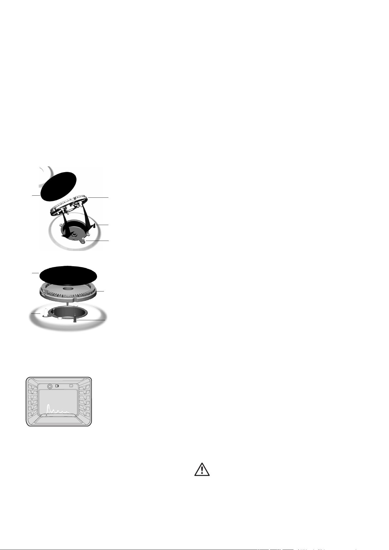
Using the gas cooker
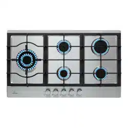
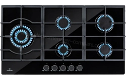
Gas hotplate
Ensure burner caps, crowns and trivets are properly
assembled.
For wok ONLY use the trivet and burner dedicated for wok
cooking.
Burner cap and burner crown must be clean and located
correctly for the burner to light.
Burner Crown
Burner
Cap
Spark Plug
Flame Sensor
(Thermocouple)
Burner
Cap
Burner Crown
Spark
Plug
Flame Sensor (Thermocouple)
Gas oven burner flame
From a cold start the oven burner flame will be higher on the
left hand-side. After reaching the set temperature, the flame
will become even. This does not affect cooking results.
LIGHTING GAS HOTPLATE, GRILL AND OVEN
Electronic ignition with flame safeguard
This hob is fitted with mains powered electronic ignition.
When the appliance has been connected and the power is
on, depressing ignite button will release sparks to all burners.
To light a burner, depress the corresponding knob fully
and while continuing to depress knob for approximately
5seconds, turn anticlockwise to ‘HI’ position. The flame
sensor must warm-up in order for the flame to stay alight.
The knob may be released once the flame is established,
and turned further anticlockwise to reduce the flame height as
desired.
•Before releasing the knob, ensure the knob is fully
depressed.
•If the flame goes out when the knob is released, simply
repeat the ignition procedure again.
Hotplate Ignition – (Manual)
To light a burner, depress the corresponding knob fully
and while continuing to depress the knob approximately
5seconds, turn anti-clockwise to 'HI' position. At the same
time, hold hand-ignitor next to the burner and ignite (hand-
ignitors not supplied). The flame sensor must warm up in
order for the flame to stay alight
Grill Ignition – Electronic
While pressing the electronic ignitor switch, depress the
corresponding knob fully and while continuing to depress
the knob for approximately 5 seconds, turn anti-clockwise to
'HI' position. The flame sensor must warm up in order for the
flame to stay alight.
Grill Ignition – Piezo
Depress the grill control knob fully and while continuing to
depress the knob for approximately 5 seconds, turn anti-
clockwise to 'HI' position. The flame sensor must warm up in
order for the flame to stay alight.
Grill – in Oven
Grill is electric and is operated by control knob only.
Oven Ignition – Electronic
While pressing the Electronic Ignitor Switch, push turn and
hold the Oven Control Knob to the desired temperature. Hold
Control Knob in for 15 seconds after ignition.
Oven Ignition – Piezo
With the left hand push and hold the Oven Control Knob in
and turn it a quarter of the way anti-clockwise. Keep the oven
Control Knob pushed in firmly and at the same time push the
Oven Piezo Ignitor button on the right hand side of the control
panel (several times if necessary). It will make a loud ‘clack’
noise as the Piezo mechanism creates a spark.
Hold control knob in for 15 seconds after ignition.
warning
•Keep hands clear of burners when lighting.
•If burner does not light within 5 seconds, turn knob to ‘Off’
position, allow gas to disperse, then try lighting again.
•Burners MUST be operated between ‘HIGH’ and ‘LOW’
settings only.
22 Chef 540 Upright Cooker
Using the electric cooker
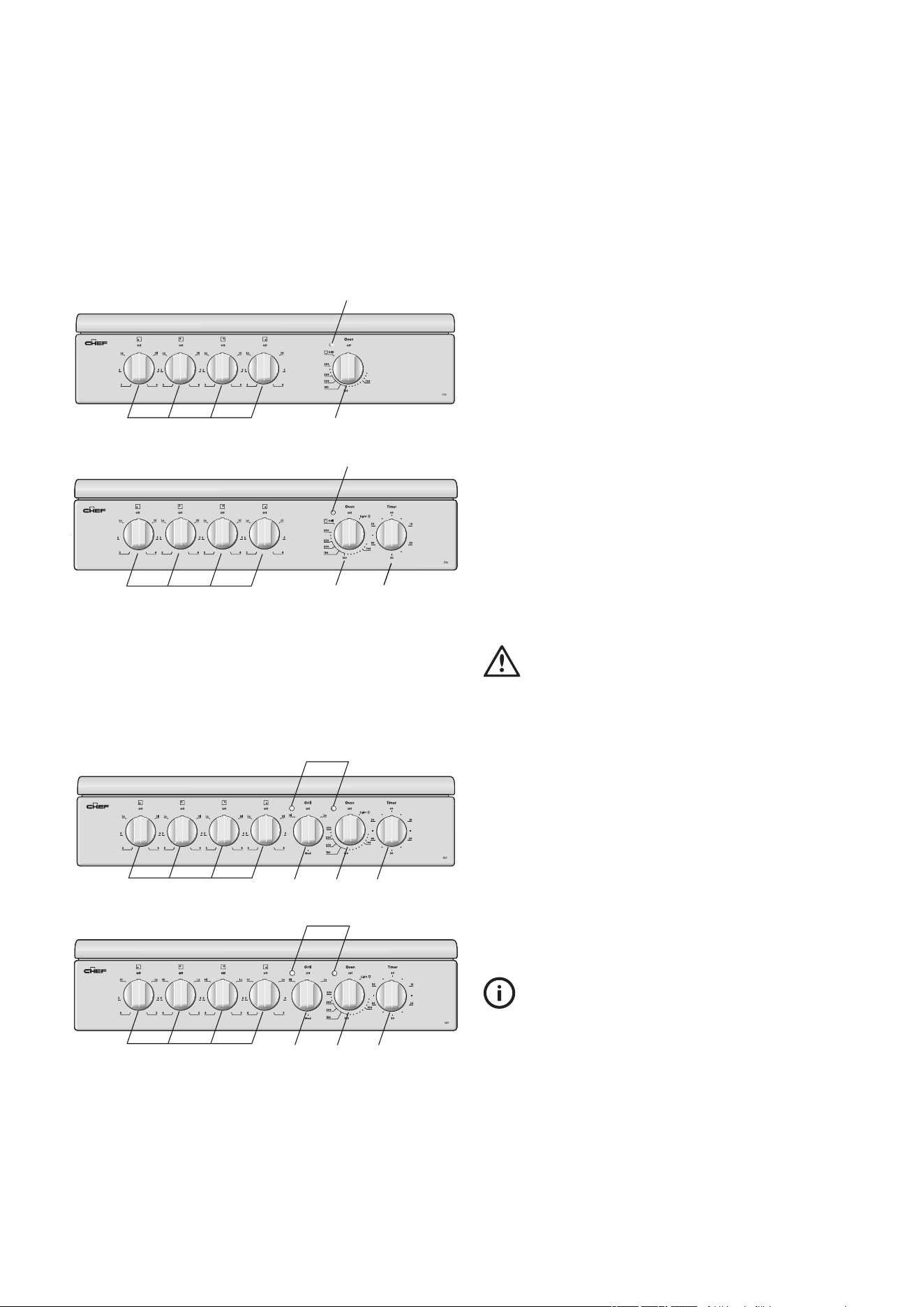
Electric features and descriptions
Grill in Oven Models
CFE532
4
1 2/3
CFE536
4
1 52/3
Separate Grill Models
CFE533 / CFE535 / CFE537
3 5
4
1 2
CFE547
1 2 3 5
4
1. Solid/Ceramic Hotplate Control Knob
– setshotplatetemperature.
2. Grill Control Knob – sets grilling temperature.
3. Oven Control Knob – sets oven temperature.
4. Grill/Oven Indicator Light(s) – Comes on when grill/oven
temperature knob is operated. Oven indicator light cycles
on and off when temperature is reached.
5. Timer 60 Minute – (where fitted) sets reminder time.
– When timer returns to zero, timer gives a short ring.
NOTE: For any time below 15 minutes, turn knob past 15
minutes, then back to required time setting.
6. Burner control knob – sets burner temperature.
7. Hotplates ignitor – ignites gas hotplates when appropriate
control knobs are set.
Solid hotplates
If present, the red dot in the centre of hotplate changes colour
when heated.
When necessary to keep element looking good, apply
coating of ‘hot plate protection’ onto solid hot plates.
Ceramic Hotplates
warning
If the surface is cracked, switch off the appliance to avoid the
possibility of electric shock.
•The ceramic cooktop is made from ceramic glass, a
tough, durable material that withstands heating and
cooling without breaking. However, it must be noted that
as it is glass, it may break, and must therefore be treated
with care. Should you have any questions about the glass
in your new appliance, please contact the service centre
by dialling 13 13 49
•The smooth glass surface has a pattern to show where the
elements under the glass are located
•When a hotplate is on, the hot surface warning light will
come on. After switching off, this light will continue to glow
until the temperature of the hotplate drops below 60°C.
Electric oven conventional baking
Heat comes from two elements, one above and one below
the food. The bottom element is hidden below the floor of the
oven. As hot air rises naturally, the upper part of the oven will
be approximately 10°C higher than the set temperature and
the lower part of the oven approximately 10°C cooler.
For Grill in Oven Models, the grill dish must be removed when
baking.
Chef 540 Upright Cooker 23
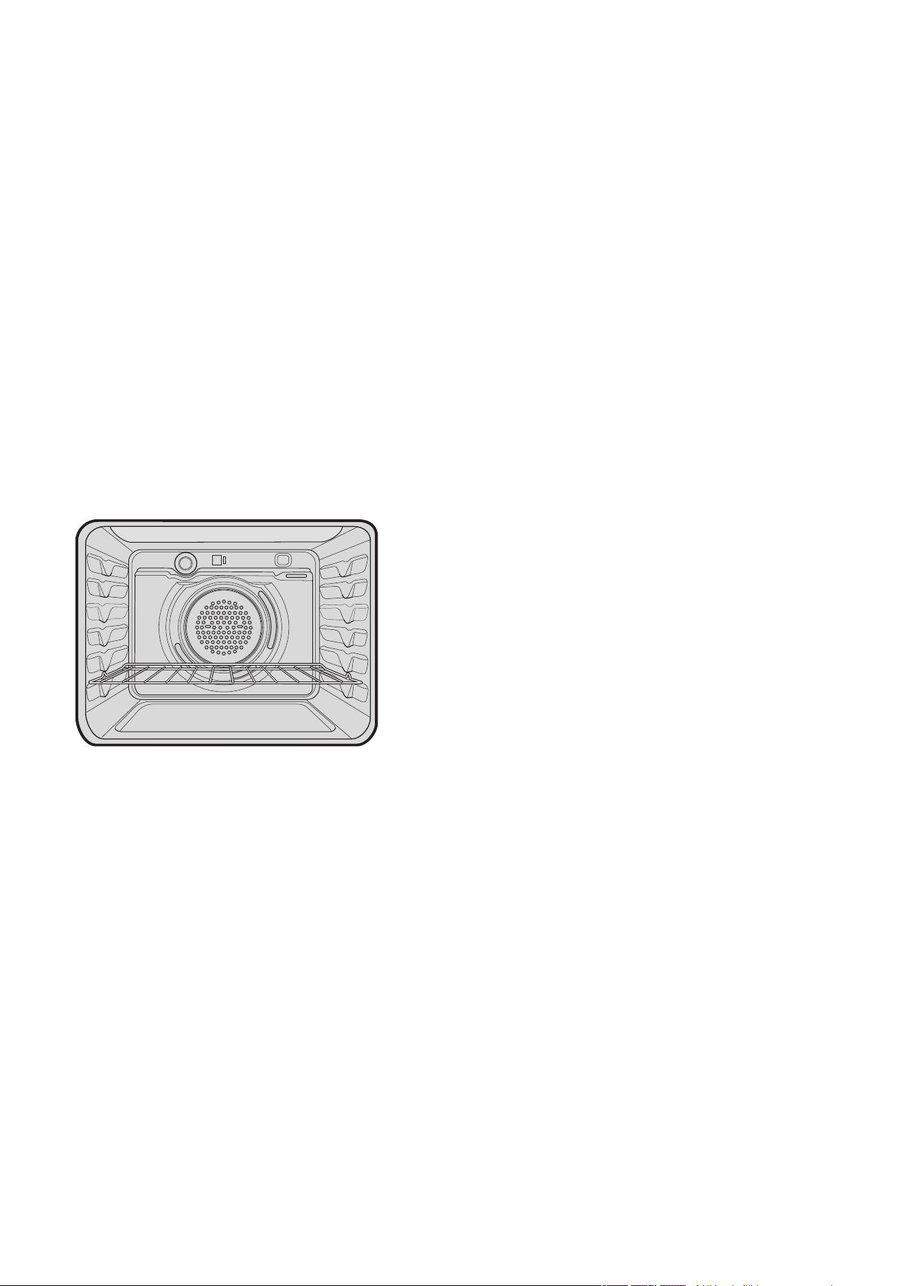
Electric oven fan forced baking
In a fan forced electric oven the heat comes from the rear
oven element. Hot air is distributed by a fan behind the rear
wall of the compartment, providing an even temperature on
all shelf levels. This means, batches of food can be baked
using multiple shelf positions simultaneously.
Fan forced operation can be used for single food baking with
equal success.
Fan Forced baking generally requires lower temperatures than
conventional baking. Most recipe books, unless stated, are
typically for conventional oven temperatures. It is recommended
that when using the fan forced mode, reduce the oven
temperature by 10 degrees (refer to ‘Oven Guide’).
Using the electric cooker
24 Chef 540 Upright Cooker
General hints and tips
Using the Grill
•Separate Grill: Grill with door open.
Grill dish must be fully inserted.
•Grill in oven: Grill with door closed.
Hints general
•For best baking results, across all models, preheat oven for
30minutes.
•The material and finish of baking trays and dishes used
will affect the way foods are baked, especially base
browning.
•Enamelware, anodised aluminium, dark bakeware or non-
stick interiors and coloured exteriors will assist in maintaining
or reducing the baking time and increase base browning
•Ovenproof glassware or ceramics are poor conductors
of heat. The shiny surface of aluminium or polished steel
utensils and trays also reflects the heat rather then passing
it through to the food being baked
•Always place dishes centrally on the shelf to ensure even
browning
•Stand casseroles dishes or similar-type dishes on suitably
sized baking trays to prevent spillage onto the base of
oven to make cleaning of oven easier
•DO NOT place dishes, trays or baking pans
directly on the oven base as they become very hot and
will crack and craze the oven liner
•Use ovenproof cookware, which will withstand
temperatures of 250°C
•DO NOT use baking trays larger than 30 x 35cm
(12x14inches) as they will restrict the circulation of the
heat and may affect cooking performance of the oven
•Use shallow casserole dishes in preference to deeper ones
as this shortens cooking time in the oven.
Conventional Oven
•The shelf position is critical. The temperature in centre of
the oven is the temperature shown on the oven control
knob. Single shelf baking gives optimal cooking results.
•DO NOT place baking trays, oven dishes or foil directly
on the base of oven, as trapped heat will crack and craze
the floor of the oven liner.
Fan Forced
•DO NOT place baking trays and oven dishes directly
against the grid covering the fan at the back of the oven
•DO NOT Place oven dishes directly on the oven base
•Make sure shelves are evenly spaced
•When baking more than one dish in fan forced oven,
place dishes centrally on shelves rather than several dishes
on one shelf
•When the oven is full you may need to allow a slightly
longer baking time
•When using different size trays or cooking different types
of food, cooking times may vary for each dish.
General tips
Condensation and Steam
•Always stand back from heated oven when opening oven
door to allow any build-up of steam or heat to release
•During cooking steam may be produced which can be
released when opening the oven door. This is quite normal
•If there is any build-up of condensation on the oven door
it is recommended that it be carefully wiped away either
during or after cooking.
Cleaning the cooker
Ovens and hotplates are made from steel and enamel. Do
not use abrasives and harsh scourers as they may scratch the
surface
Do not use steam cleaners
Stainless Steel
•All grades of stainless steel can stain, discolour or become
greasy. You must clean these areas regularly by following
the procedures below if you want your appliance to look
its best, perform well and have a long life
•Care must be taken when wiping exposed stainless steel
edges as they can be sharp
•The front frame around the oven can be cleaned with
stainless steel cleaners if it comes soiled or discoloured
•A suitable cleaner can be purchased from Electrolux
Customer Care Centres
•Make sure you follow the polish or brushing lines in the
steel.
General
•Always clean appliance after use, especially food
spillage. DO NOT use steel wool, wax polishes or caustic
based commercial cleaners as these will damage your
oven
•DO NOT use steam cleaners, as this may cause moisture
build-up especially in the glass door
•Door Glass – DO NOT use harsh abrasive cleaners or
sharp metal scrapers to clean glass since they can scratch
the surface, which may result in shattering of the glass.
warning
Door glass is a tough and durable material designed to
withstand heating and cooling without breaking. However it
must be remembered that it is glass and may break, therefore
must be treated with care.
If you have any questions about the glass in the oven please
contact the Service centre on 13 13 49.
Chef 540 Upright Cooker 25
General hints and tips
Cleaning the Oven Door
Cool air circulates through the door to lower the surface
temperature on the outside of the oven door.
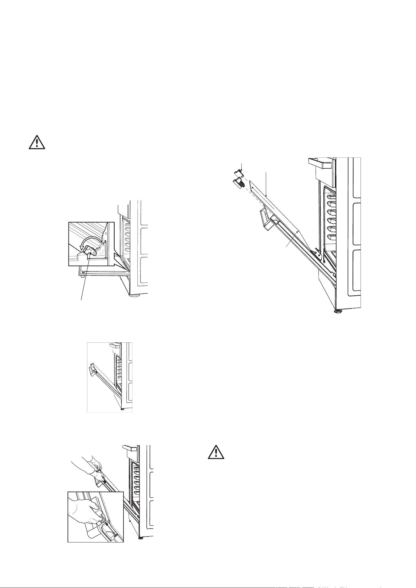
•
Do not remove the oven door
•This product has a removable inner door glass.
To remove the inner door glass for cleaning
•Open the door fully to access the hinges then rotate the
“stirrups” on both hinges fully towards the door.
Stirrup
•Slowly close the door until it stops against the ‘stirrups’
(about 45°)
•To remove the top trims (2 off), press the ribbed release
clips at each end and lift top trim away from the door.
•Using both hands, gently remove the inner glass by sliding
out and lifting away from the door
•Inner door glass: some products have heat reflective glass
on the inner door glass. These are identified by a black
dot on the lower left hand corner of the inner door glass.
The black dot to be
located on the lower
left hand corner where
applicable
Inner glass
Top trims
•Wipe inner and outer glass gently with detergent and
warm water
•Wipe clean and dry thoroughly.
Re-Assembling the oven door inner glass
•Replace the inner glass back to the door with the black dot
located on the lower left hand corner where applicable
•Replace the top trim ensuring the clips snap back into
position
•Fully open the door, rotate the stirrups back to their original
position and close the door.
warning
DO NOT use the oven without the inner door glass fitted.
DO NOT use harsh abrasives on glass as this may damage
the glass
DO NOT place glass in dishwasher.
Hand wash only with a soft cloth and warm soapy water.
When dry, polish with a soft cloth and ensure the glass is dry
before re-assembly.
26 Chef 540 Upright Cooker
caution
•Ensure the appliance is off and cool before cleaning.
Oven
•
Do not remove the oven door
•Make sure oven knobs are in the off position
•Clean immediately after use as a warm oven is easier to
clean
•Use detergent, hot water (and household ammonia/
cloudy ammonia if necessary) and a soft cloth. Dry
thoroughly.
•Remove shelves when cleaning oven
•If there is a build-up of grease, place a small oven proof
dish containing ¼ cup (62mL) household ammonia/
cloudy ammonia and ¾ cup (187mL) water in the oven.
Heat oven to 110 degrees and turn oven off when 110
degrees is reached. Leave over-night. The fumes will loosen
stubborn grease and stains. Remove bowl, wash with hot,
soapy water and dry well before closing oven door again.
Oven Shelves
•Chrome shelves: use detergent and hot water. If very dirty
use a non-abrasive nylon scourer
•Enamel dishes and tray: use detergent and hot water. If
very dirty a non-abrasive nylon scourer
•DO NOT clean oven parts with abrasive or caustic-type
cleaners.
Oven – Grill Dish and Insert
•After every use, and while still warm, sprinkle grill insert
with detergent and cover with wet paper towel as this will
loosen food particles and grease
•Wash pan and grid with hot, soapy water with a little
household ammonia/cloudy ammonia added. Rinse and
dry before replacing in position.
caution
•If the ceramic glass surface is cracked, switch off the
appliance immediately to avoid the possibility of electric
shock.
Ceramic Hotplates
•Clean with detergent and hot water and polish with a soft
cloth
•For harder to clean spills a blade scraper is supplied
•Aluminium foil, plastic and high sugar content food can
cause pitting if not removed before the hotplate has
cooled.
•Sometimes SURFACE stains appear to be ‘bubble’ marks
under the ceramic glass. These can be cleaned off with a
razor blade scraper and ceramic cleaner.
Solid Hotplates
•Solid hotplates are fitted with stainless steel trim rings,
which after initial use, change colour to light brown.
Thisis a normal characteristic of stainless steel and will not
affect the operation or performance of your hotplates
•Clean off any spillage after hot plate has cooled down
•At regular intervals, clean hotplate with a nylon scouring
pad and soapy water. Wipe clean then warm hotplate for
30 seconds to dry the surface
•Apply ‘hot plate protector’’. Set hotplate on high for
3minutes to allow coating to harden.
Gas Trivets and Burners
•Flame port blockages should be removed with a small
metal cake skewer or nylon brush.
•Clean dirty spark plugs very gently with a nylon scourer.
DO NOT use steel wool. DO NOT bend spark plug as it
may break.
•For enamelled burner skirts and trivets, persistent stains
may require rubbing with a nylon scourer or creamed
powder cleansers. Household enamel cleaners are
available, follow the manufacturer’s instructions in their
use. Harsh abrasive cleaners, powder cleaners, steel wool
or wax polishes should not be used.
•These can all be lifted off and removed for separate
cleaning.
•NOTE! When refitting the burners, ensure that they are
correctly seated.
•Ensure burners are thoroughly dried after cleaning or
spillage. When cleaning the burners, ensure that all the
flame ports are free of any blockage (refer to Figure 1b
on page 4). If necessary, use a toothpick or brush to
clear ports. The outer surface of the burner caps have
a polished finish and extra care needs to be taken to
avoid scratching this surface during cleaning. In instances
of heavy soiling, it may be necessary to apply a non-
abrasive cleaning compound and rub with a cloth until the
soiling is removed and then finish with a soft, dry cloth.
•NOTE! DO NOT place trivets or burners in the
dishwasher.
Stainless steel (Models with Stainless Steel hob)
•Simply wipe with a soft cloth using warm water and a
mild detergent and rinse with clean water. Where stainless
steel has become extremely dirty or discoloured, use a
stainless steel cleaner – but be sure to follow the brushing
lines.
Cleaning the cooker
Chef 540 Upright Cooker 27
Cleaning the cooker
Ignition spark plug and flame safeguard sensor
GENTLY clean the ignition spark plug and flame safeguard sensor with a damp cloth to avoid lighting difficulties.
Ensure that they are dry before use.
Injector
Ensure the injector remains free of any foreign material. When cleaning the burner spill bowl, first put tape over the injector hole before
wipe out the spill bowl to avoid to block the injector hole, then remove the tape after cleaning.
If necessary, use a thin piece of wire to clear the orifice.
Do’sDon’ts
Use pots with a flat base.
Do not slide pots across the glass as this can results in scratches to the
surface
Clean when cold unless sugar spills which should be removed with a
ceramic scraper.
Do not clean when hot as it is dangerous and cleaning products can
burn and stain.
Clean after every use with a sponge and soapy water then dry.
Do not leave food residues or water on the ceramic as the
contamination can damage the ceramic and screening printed
graphics
Use a non-scratch scourer (usually blue in colour) if required.
Do not use steel wool or scourer pads that are not specified as non-
scratch (usually green in colour). Heavy duty scourers are too abrasive
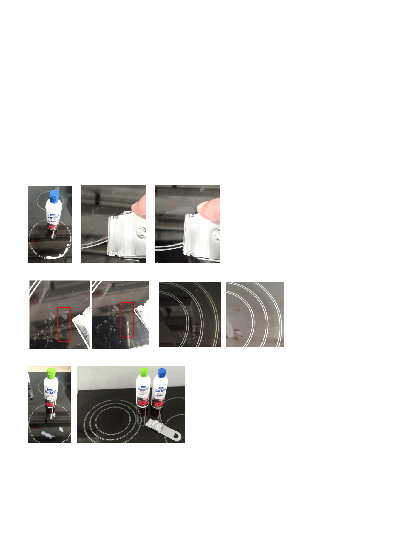
Difficult stains should be removed with a ceramic scraper and
cleaning cream specific for ceramic glass cooktops. Cerapol
Do not use general abrasive cleaners as these can cause micro-
scratches, dulling the glass surface and increasing the likelihood of
contamination embedding into the glass
At least once per week use ceramic sealer cream. Ceraseal
Do not use the ceramic top as a cutting board or work bench as this
will cause scratches.
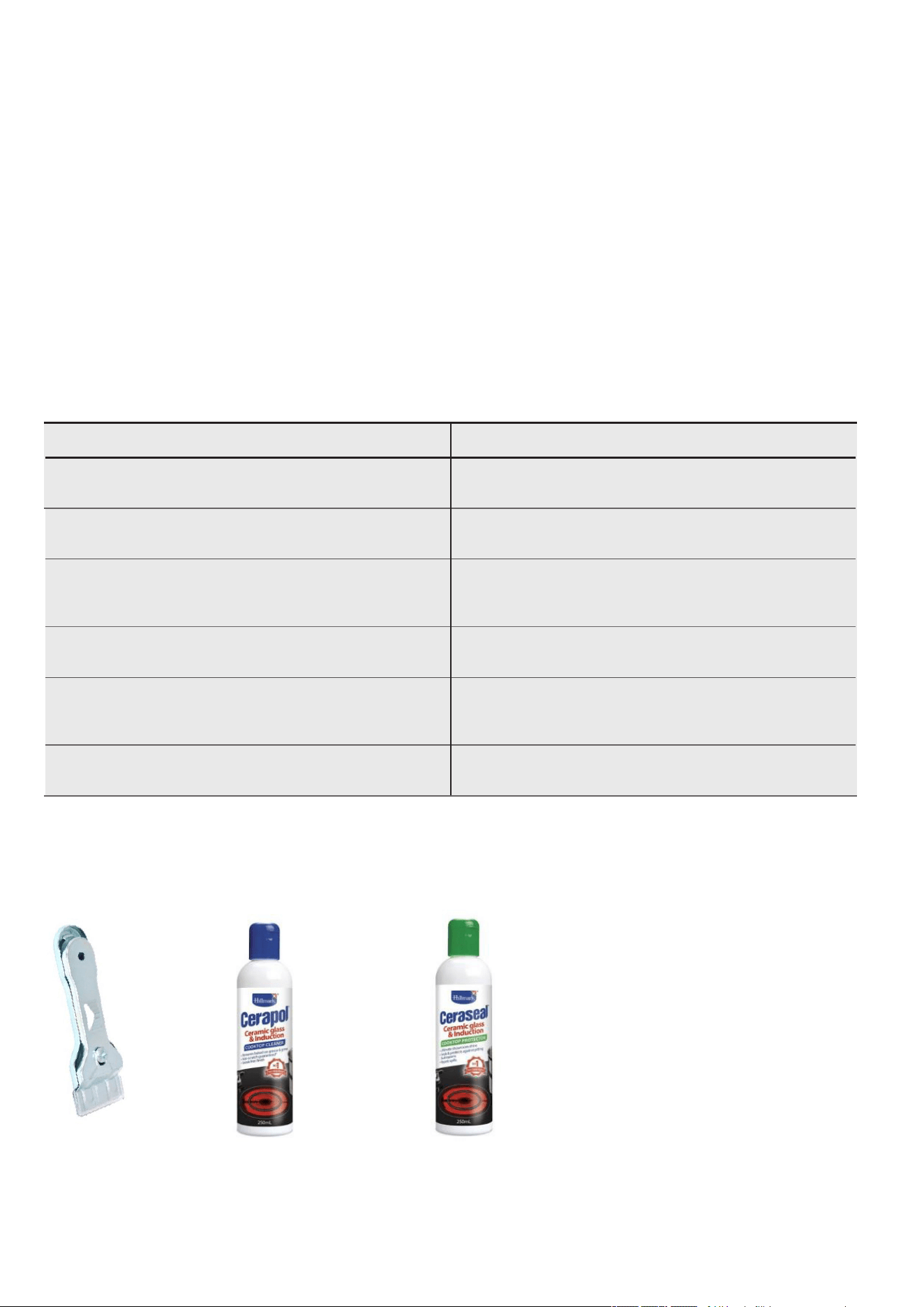
Ceramic Cooktop Cleaning
CUSTOMER ADVICE
Sometimes SURFACE stains appear to be a “bubble” mark under the ceramic glass.
These can be cleaned off with a razor blade scraper and ceramic cleaner.
Keeping the ceramic cooktop clean and protected will keep it in good condition and help avoid breakage.
Ceramic
Scraper
0383001001
Cerapol
Cleaner
ACC019
Ceraseal
Protector
ACC018
Available at the following web shops.
https://shop.electrolux.com.au
28 Chef 540 Upright Cooker
If the deposit is minimal, simply wipe off with a dry cloth.
If the deposit is more stubborn, clean off with a moist soapy sponge then rinse off.
If the deposit still does not clean off easily, use a non-abrasive nylon scratch pad and special purpose ceramic glass cleaning agent
such as Cerapol cleaner (ACC019 - Available from our web shop).
If the deposits are still burnt on and above methods did not work, use a specially designed ceramic glass scraper
(0383001001-Available from our web shop).
After having successful cleaned the cooktop, apply a ceramic glass conditioner Ceraseal protector (ACC018 - Available from our
web shop). The conditioner will leave a protective coating that will help prevent future stains from becoming baked on. Marks which
appear to be bubbles under the ceramic will also clean off. Use Ceraseal (ACC018) to help protect the ceramic and allow for easier
cleaning. Polish on with a dry clean cloth.
Marks which appear to be bubbles under the ceramic will also clean off.
Use Ceraseal (ACC018) to help protect the ceramic and allow for easier cleaning. Polish on with a dry clean cloth.
Cleaning the cooker
Chef 540 Upright Cooker 29
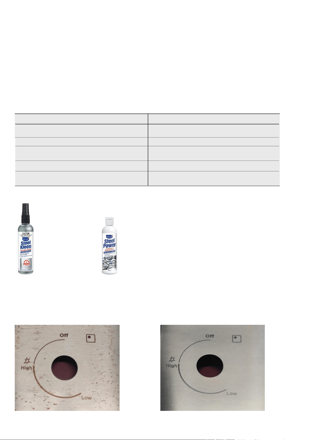
Stainless Steel Cooktop Cleaning
NOTE: Ensure any oil is cleaned off the hob before use, otherwise it may cause the hob to turn a yellowish colour. All
grades of stainless steel may stain, discolour or attain an adhering layer of grime in normal operation. To achieve maximum
surface appearance, stainless steel must be kept clean.
Do’sDon’ts
Clean in the direction of stainless steel brushing lines.
Do not clean against the stainless steel brushing lines as this will
cause scratching.
Wash with warm soapy water. Do not use caustic cleaners.
For stains use a specific stainless-steel cleaner ACC031.
Do not use abrasive cleaners, scourers or steel wool as this will
cause scratching.
Always clean the stainless steel after food spillage.Some foods may discolour the stainless steel.
Use the correct sized pot as described in the owner manual.
Do not oversized pots as they can reflect heat onto the stainless
steel causing discolouration.
NOTE: Do not use stainless steel cleaners on oven doors or control panels with finger print proof coating. Refer to owner
manual for specific models.
Steel Kleen
ACC032
Steel Power
ACC031
Available at the following web shops or distributors.
https://shop.electrolux.com.au/
Remove deposits with a soft cloth and warm soapy water then wipe with a dry soft cloth. If there are signs of yellowing or stubborn
stains, use a suitable stainless steel cleaner Steel Kleen (ACC032 - Available from our web shop), apply with a soft cloth and clean
in the direction of the stainless steel grain only.
After the cooktop is clean, apply stainless steel protectant Steel Power (ACC031 - Available from our web shop) which will leave a
protective coating to help prevent future stains from occurring.
Before After
Cleaning the cooker

30 Chef 540 Upright Cooker
Getting to know your oven
Getting to know your new oven with this
‘Simple Test Cake’
When baking, it is possible that there will be some variation in
colour. Therefore, we suggest to make this simple, easy and
delicious test cake to help you understand your new oven.
All ovens do sometimes have hot or cold spots, therefore it is
important to judge with your eye as you may need to rotate your
dishes during baking.
‘Simple Test Cake’
125g butter, softened to room temperature
1 cup caster sugar
1 teaspoon pure vanilla essence
4 large eggs
2 cups self-raising flour
pinch of salt
4 tablespoons (80mL) full-cream milk
Method:
1.Butter base and sides of two, 20cm straight-sided round
or square cake pans. Then line the base with grease proof
paper or baking paper.
2.Preheat oven to moderate ‘180ºC’ (170ºC fan forced) for
30m and ensure oven shelf is in position 2 of the oven.
3.Cream softened butter and sugar until light in colour.
4.Add vanilla essence.
5.Add eggs one at a time, beating well after each addition.
6.Sift flour and salt into the mixture and beat until well
combined.
7.Add milk and beat or stir to combine.
8.Spoon mixture equally between prepared cake pans.
9.Bake in preheated oven, position 2 for about 25 to 35
minutes. Tip: Insert a fine cake skewer into the cake mix. If
it comes out clean, or if the edges of the cake have come
away slightly from the sides of the cake pan, the cake is
ready.
10.Remove from oven and place on wire cake rack and rest for
5 minutes before removing from cake pans. Cool completely.
To Serve: sandwich together with your favourite jam or
conserve, and dust top with pure icing sugar.
FOOT NOTE: if desired, substitute butter for either margarine
or olive oil spread.
Recipe is based on the Australian standard metric 250mL cup
and 20mL tablespoon sets.
Chef 540 Upright Cooker 31
Oven guide
The following is intended as a guide and experience may show some slight variation in order to meet individual requirements.
Where the gas models vary from the electric models, details for gas cooking is shown in brackets. For best results when
baking, preheat your oven for 30 minutes.
FoodConventional OvenFan forced ovenTime in minutes
Temperature °C Oven shelf position* Temperature °C Oven shelf position*
Plain or fruit scones2202 (3)210Any10 –15
Rolled biscuits
Spooned biscuits
Shortbread biscuits
170 (180)2150 (170)Any10 –15
1902180Any12 –15
1601 or 2150Any30 – 35
Hard individual meringues
Soft individual meringues
Pavlova – 6 eggs
1102100Any90
1802165Any15 – 20
110 (120)1100Any75
Cup cakes
Sponge – 4 eggs
Plain butter cake
Rich fruit cake
1902180Any15 – 20
1802170Any20 – 30
1802170Any25 – 40
140 (150)2130Any180
Shortcrust cornish pasty
#
200 (200/180)2180 (180/160)Any40 – 45 (10/35)
Shortcrust custard tart
200/180 (220/180)
1(3)190/170 (200/180)Any20 – 30 (10/25)
Cream puffs2102200Any25 – 30
Yeast bread2101200Any25 – 30
Pizza2202220Any15 – 25
* Shelf position is counted from the bottom shelf up. Bottom shelf position is 1.
# Turn down temperatures shown.
Meat/Poultry/FishRecommended temperature
0
CMinutes per kilogram
Beef – Rare20035 - 40
– Medium20045 - 50
– Well done20055 - 60
Lamb – Medium20040
– Well done20060
V
eal18060
Pork20060
Chicken180 - 200
45 – 50
Duck180 - 200
60
– 70
Turkey180
40
– 45 (less than10kg)
35
– 40 (more than10kg)
Fish18020
32 Chef 540 Upright Cooker
Troubleshooting
ProblemCausesWhat to do
Uneven cookingIncorrect shelf positionSelect shelf that puts food in centre of oven
Oven tray too largeTry other trays or dishes
Trays not in centrePut trays in centre
Air flow in oven unevenRotate food during cooking
Grill tray affecting thermostatRemove grill tray from oven on bake modes
Baked products too brown on topOven not preheatedPreheat the oven
Baking tins too large for recipeUse correct size tins
Baking tins not evenly spacedStagger baking tins at least 3cm between tins and
the oven walls
Products not evenly sized or spaced on tray
s
Make into same size and shape and spread
evenly over trays
Baked products too brown on
bottom
Baking tins too largeUse correct size tins
Baking tins are dark metal or glassChange to shiny, light tins or lower the
temperature by 10°C
Food too low in ovenCook one shelf higher
Oven door opened too frequently during
baking
Don’t open the oven door until at least half the
cooking time has passed
Baking temperature too highLower the temperature
Grill tray affecting thermostatRemove grill tray from oven on bake modes
Cakes have a cracked thick crustBaking temperature too highLower the temperature
Food too low in ovenCook one shelf higher
Cake batter over mixedMix just long enough to combine the ingredients
Baking tin too deepCheck size of tin and use recommended size
Baking tins darkChange to shiny light tins
Baked products are pale, flat and
undercooked
Baking temperature too lowRaise the temperature
Food too low in ovenCook one shelf higher
Baking time too shortIncrease cooking time
Incorrect baking tin sizeUse correct size tin
Cakes fallen in centreBaking temperature too lowRaise the temperature
Baking time too shortIncrease cooking time
Proportions of ingredients incorrect for recipeCheck recipe
Opening door too early during bakingDo not open door until the last quarter of cooking
time
Roast meat and potatoes not brown
in fan oven
Poor hot air circulationElevate food onto a rack to allow air circulation
Grill tray affecting thermostatRemove grill tray from oven on bake modes
Juices running out of meatDo not pierce meat with fork, turn with tongs
Grilled meats overcooked on
outside and raw in the centre
Grill at lower insert position
Grilled chops and steaks curlingCut into fat every 2cm (¾")
The oven seal is looseThe oven seal is only attached at each corner. It
may seem like loose fit but when the oven door is
closed it will function correctly.
Chef 540 Upright Cooker 33
Troubleshooting
If you have a problem with your appliance check the following before you ring the service line.
ProblemWhat to do
Operational problems
ie: Oven, grill or hob not working
Check the electricity is turned on
Check your fuses. If the fuse continues to blow, call the Service Centre
Check the circuit breaker
Ensure correct knob is turned
Gas only – Dry or clean ignition electrodes
Gas only – Make sure flame ports and ignition areas are clean and dry
Gas only – Check gas supply is on
Gas only – Ensure cap/crown correctly fitted.
Replace or tighten light globes (where fitted)
See also Gas Conversion Fault Finding on Page 17
Heat up problemsOven not pre-heated – Pre-heat oven for 30 minutes
Check oven door is closed properly
Remove foil or trays from bottom of oven
Change set oven temperature
Preheat your oven/grill before you put the food in to be cooked
Unit smoking odoursTurn oven/grill on high to remove protective oils
Persistent gas smell – do not operate appliance. Call service 131349
Condensation
Note: some condensation is normal and
is to be expected during cooking
Reduce the amount of water used for cooking
Leave the door open after cooking if food remains in cooker for warming
Timer not audibleTurn Timer knob past 15-minute mark then to the required number of minutes
Oven shelf tightRemove shelf and insert as per diagram
Stains appear to be under ceramicThese stains are on the SURFACE of the glass and can be cleaned off with a razor blade
scraper and ceramic glass cleaner.
When you need information, service or replacements please quote:
1.Model Number
2.Serial Number: You can find these on the data plate, which can be seen when the oven door is open. If you need more information, please contact the
Customer Care Centre on 13 13 49 (Australia – Centre is open 8.00am to 5.00pm Monday to Friday EST) Or 0800 436 245 (New Zealand –Centre
is open 8.00am to 5.00pm Monday to Friday). Only authorised service centres should carry out servicing. Otherwise warranty may be void. Ifyou have a
warranty or spare parts enquiry, you should call the numbers listed on the back page.

34 Chef 540 Upright Cooker
Warranty
FOR SALES IN AUSTRALIA AND NEW ZEALAND
APPLIANCE: CHEF BUILT-IN OVENS, COOKTOPS AND FREESTANDING
COOKER
This document sets out the terms and conditions of the
product warranties for Chef Appliances. It is an important
document. Please keep it with your proof of purchase
documents in a safe place for future reference should there be
a manufacturing defect in your Appliance. This warranty is in
addition to other rights you may have under the Australian
Consumer Law.
1.In this warranty:
(a)‘ACL’ or ‘Australian Consumer Law’ means Schedule 2 to the
Competition and Consumer Act 2010;
(b)‘Appliance’ means any Electrolux product purchased by you and
accompanied by this document;
(c)‘ASC’ means Electrolux’s authorised serviced centres;
(d)‘Chef’ is the brand controlled by Electrolux Home Products Pty Ltd of
163 O’Riordan Street, Mascot NSW 2020, ABN 51 004 762 341
in respect of Appliances purchased in Australia and Electrolux (NZ)
Limited (collectively “Electrolux”) of 3-5 Niall Burgess Road, Mount
Wellington, in respect of Appliances purchased in New Zealand;
(e)‘Warranty Period’ means the period specified in clause 3 of this
warranty;
(f)‘you’ means the purchaser of the Appliance not having purchased the
Appliance for re-sale, and ‘your’ has a corresponding meaning.
2.Application: This warranty only applies to new Appliances, purchased
and used in Australia or New Zealand and is in addition to (and does not
exclude, restrict, or modify in any way) other rights and remedies under
a law to which the Appliances or services relate, including any non-
excludable statutory guarantees in Australia and New Zealand.
3.Warranty Period: Subject to these terms and conditions, this warranty
continues in Australia for a period of 24 months and in New Zealand
for a period of 24 months, following the date of original purchase of the
Appliance.
4.Repair or replace warranty: During the Warranty Period, Electrolux
or its ASC will, at no extra charge if your Appliance is readily accessible
for service, without special equipment and subject to these terms and
conditions, repair or replace any parts which it considers to be defective.
Electrolux may, in its absolute discretion, choose whether the remedy
offered for a valid warranty claim is repair or replacement. Electrolux or its
ASC may use refurbished parts to repair your Appliance. You agree that
any replaced Appliances or parts become the property of Electrolux.
5.Travel and transportation costs: Subject to clause 7, Electrolux
will bear the reasonable cost of transportation, travel and delivery of the
Appliance to and from Electrolux or its ASC. Travel and transportation will
be arranged by Electrolux as part of any valid warranty claim.
6.Proof of purchase is required before you can make a claim under this
warranty.
7.Exclusions: You may not make a claim under this warranty unless the
defect claimed is due to faulty or defective parts or workmanship. This
warranty does not cover:
(a)light globes, batteries, filters or similar perishable parts;
(b)parts and Appliances not supplied by Electrolux;
(c)cosmetic damage which does not affect the operation of the
Appliance;
(d)damage to the Appliance caused by:
(i)negligence or accident;
(ii)misuse or abuse, including failure to properly maintain or service;
(iii) improper, negligent or faulty servicing or repair works done by
anyone other than an Electrolux authorised repairer or ASC;
(iv)normal wear and tear;
(v)power surges, electrical storm damage or incorrect power supply;
(vi)incomplete or improper installation;
(vii)incorr ect, improper or inappropriate operation;
(viii) insect or vermin infestation;
(ix)failure to comply with any additional instructions supplied with the
Appliance;
In addition, Electrolux is not liable under this warranty if:
(a)the Appliance has been, or Electrolux reasonably believes that the
Appliance has been, used for purposes other than those for which the
Appliance was intended, including where the Appliance has been
used for any non-domestic purpose;
(b)the Appliance is modified without authority from Electrolux in writing;
(c)the Appliance’s serial number or warranty seal has been removed or
defaced
8.How to claim under this warranty: To enquire about claiming
under this warranty, please follow these steps:
(a)carefully check the operating instructions, user manual and the terms
of this warranty;
(b)have the model and serial number of the Appliance available;
(c)have the proof of purchase (e.g. an invoice) available;
(d)telephone the numbers shown below.
9.Australia: For Appliances and services provided by Electrolux in
Australia: Electrolux goods come with guarantees that cannot be excluded
under the Australian Consumer Law. You are entitled to a replacement or
refund for a major failure and for compensation for any other reasonably
foreseeable loss or damage. You are also entitled to have the Appliance
repaired or replaced if the Appliance fails to be of acceptable quality and
the failure does not amount to a major failure. ‘Acceptable quality’ and
‘major failure’ have the same meaning as referred to in the ACL.
10. New Zealand: For Appliances and services provided by Electrolux
in New Zealand, the Appliances come with a guarantee by Electrolux
pursuant to the provisions of the Consumer Guarantees Act, the Sale
of Goods Act and the Fair Trading Act. Where the Appliance was
purchased in New Zealand for commercial purposes the Consumer
Guarantee Act does not apply.
11. Confidentiality: You accept that if you make a warranty claim,
Electrolux and its agents including ASC may exchange information in
relation to you to enable Electrolux to meet its obligations under this
warranty.
Important Notice
Before calling for service, please ensure that the steps listed in clause 8 above have been followed.
AUSTRALIA
FOR SERVICE
or to find the address of your nearest
authorised service centre in Australia
PLEASE CALL 13 13 49
For the cost of a local call
FOR SPARE PARTS
or to find the address of your nearest
spare parts centre in Australia
PLEASE CALL 13 13 50
For the cost of a local call
NEW ZEALAND
FOR SERVICE
or to find the address of your nearest
authorised service centre in New
Zealand
PLEASE CALL 0800 10 66 10
FOR SPARE PARTS
or to find the address of your nearest
spare parts centre in New Zealand
PLEASE CALL 0800 10 66 20
CCook_Warr_ Jul19

Chef 540 Upright Cooker 35
NOTES

Chef. We are part of the Electrolux family.
Share more of our thinking at electrolux.com.au
ANC A03786307 Rev A
© 2024 Electrolux Home Products Pty Ltd
ABN 51 004 762 341
C_MAN_Upright_Front_Control_Gas_Conversion_Apr24
For further information on all Chef appliances, or to obtain
detailed dimension and installation information, call into your
Retailer, phone or email our Customer Care team or visit our
website:
Australia
phone:
..........................................................13 13 49
email:
.............................[email protected]
web:
............................................chefappliances.com.au
Like to know more?