
2 Rinnai Commercial Boiler Installation and Operation Manual
Copyright 2024 Rinnai America Corporaon. Rinnai® is a registered trademark of Rinnai Corporaon
used under license by Rinnai America Corporaon. Rinnai America Corporaon connually updates
materials, and as such, content is subject to change without noce.
If the informaon in these instrucons is not followed exactly, a re or explosion may result
causing property damage, personal injury or loss of life.
• Do not store or use gasoline or other ammable vapors and liquids in the vicinity of this or
any other appliance.
• WHAT TO DO IF YOU SMELL GAS
− Do not try to light any appliance.
− Do not touch any electrical switch; do not use any phone in your building.
− Immediately call your gas supplier from a neighbor’s phone. Follow the gas supplier’s
instrucons.
− If you cannot reach your gas supplier, call the re department.
• Installaon and service must be performed by a licensed professional.
WARNING

Rinnai Commercial Boiler Installation and Operation Manual 3
1. Welcome ................................................................................................................................................ 5
1.1 To The Consumer ......................................................................................................................... 5
1.2 To The Installer ............................................................................................................................ 5
1.3 Acronyms and Abbreviaons ....................................................................................................... 5
2. Safety...................................................................................................................................................... 6
2.1 Safety Symbols ............................................................................................................................. 6
2.2 Safety Precauons ........................................................................................................................ 6
3. About the Boiler ..................................................................................................................................... 8
3.1 Front View ................................................................................................................................... 8
3.2 Back View .................................................................................................................................... 8
3.3 Components ................................................................................................................................ 9
3.4 Altude ...................................................................................................................................... 13
3.5 Specicaons ............................................................................................................................. 14
3.6 Dimensions ................................................................................................................................ 15
3.7 Included Accessories .................................................................................................................. 17
3.8 Oponal Accessories .................................................................................................................. 18
4. Installaon............................................................................................................................................ 20
4.1 Installaon Guidelines ............................................................................................................... 20
4.2 What You Will Need ................................................................................................................... 21
4.3 Choose an Installaon Locaon ................................................................................................. 22
4.4 Prepare the Boiler ...................................................................................................................... 25
4.5 Fill the Condensate Collector ..................................................................................................... 25
5. Venng ................................................................................................................................................. 26
5.1 Guidelines .................................................................................................................................. 26
5.2 Venng Installaon Sequence .................................................................................................... 27
5.3 Terminaon Consideraons ....................................................................................................... 27
5.4 PVC Venng Safety Switch ......................................................................................................... 28
5.5 Venng Opons .......................................................................................................................... 29
6. Gas Supply ............................................................................................................................................ 49
6.1 Connect the Gas Supply ............................................................................................................. 49
6.2 Gas Operang Instrucons ......................................................................................................... 50
6.3 Gas Pipe Sizing Reference Tables ............................................................................................... 51
7. CH System Piping .................................................................................................................................. 54
7.1 Guidelines .................................................................................................................................. 54
7.2 Instrucons ................................................................................................................................ 54
7.3 Common CH Components .......................................................................................................... 55
7.4 Hydraulic Separaon .................................................................................................................. 60
7.5 Connect the Pressure Relief Valves ............................................................................................ 62
7.6 Connect the Condensate Drain Line ........................................................................................... 63
8. DHW System Piping with Indirect Tank ................................................................................................ 64
8.1 Guidelines .................................................................................................................................. 64
8.2 Indirect Tank Control Opons .................................................................................................... 64
9. Power Supply ....................................................................................................................................... 69
9.1 Guidelines .................................................................................................................................. 69
9.2 Electrical Connecons ................................................................................................................ 70
9.3 Post-Power Supply Connecon Checklist ................................................................................... 73
10. Commissioning ................................................................................................................................... 74
10.1 Safety Precauons ................................................................................................................... 74
10.2 Filling Process .......................................................................................................................... 74
10.3 Deaeraon Process .................................................................................................................. 75

4 Rinnai Commercial Boiler Installation and Operation Manual
11. Post-Installaon Checklist .................................................................................................................. 76
12. Operaon ........................................................................................................................................... 78
12.1 Start-Up Informaon ................................................................................................................ 78
12.2 Control Panel ........................................................................................................................... 79
12.3 Error and Diagnosc Codes .................................................................................................... 101
12.4 Perform Combuson Analysis ................................................................................................ 108
12.5 Operang Informaon ........................................................................................................... 110
13. Maintenance .................................................................................................................................... 114
13.1 Owner Maintenance ............................................................................................................... 114
13.2 Licensed Professional Maintenance ....................................................................................... 115
13.3 Service of Heat Exchanger ...................................................................................................... 118
13.4 Instrucons to Clean Condensate Trap ................................................................................... 120
13.5 Test the Ignion Safety Shut O Device ................................................................................. 121
14. Appendices ....................................................................................................................................... 122
14.1 Flush the CH Plumbing System ............................................................................................... 122
14.2 Ladder Diagram...................................................................................................................... 126
14.3 Wi-Fi Connecvity .................................................................................................................. 127
14.4 Ethernet Connecvity ............................................................................................................ 128
14.5 Building Management System (BMS) .................................................................................... 129
14.6 Remove a Boiler from a Common Vent System ...................................................................... 132
14.7 Massachuses State Gas Regulaons..................................................................................... 133
14.8 Warranty ............................................................................................................................... 134
Rinnai Commercial Boiler Installation and Operation Manual 5
Thank you for purchasing a Rinnai Condensing
Boiler. Before installing and operang this
boiler, be sure to read these instrucons
completely and carefully to familiarize
yourself with the boiler’s features and
funconality.
ANSI
American Naonal Standards
Instute
Btu Brish Thermal Unit
CH Central Heang
SOLO
Heang only boiler capable of
DHW through an indirect tank
DHW Domesc Hot Water
GPM Gallons per minute
LP Liquid Propane
LWCO Low Water Cut O
NG Natural Gas
PP Polypropylene
PRV Pressure Relief Valve
PSI Pounds per square inch
wc Inches water column
• A trained and qualied professional must
install the boiler, inspect it, and leak test
it before use. The warranty will be voided
due to any improper installaon.
• The trained and qualied professional
should have skills such as:
− Gas line sizing
− Connecng gas lines, water lines,
valves, and electricity
− Knowledge of applicable naonal,
state, and local codes
− Installing venng through a wall or
roof
− Training in installaon of condensing
boilers. Training on Rinnai
Condensing Boilers is accessible at:
rinnaipro.myabsorb.com.
Following is a list of common acronyms and
abbreviaons used in this manual:
• You must read the enre manual to
properly operate the boiler.
• Keep this manual for future reference.
• As when using any appliance generang
heat, there are certain safety precauons
you should follow. See secon “2.2 Safety
Precauons” for detailed safety
precauons.
• Be sure your boiler is installed by a
licensed installer.
• If installing in the state of Massachuses,
read secon “14.6 Massachuses State
Gas Regulaons” in this manual.
• Read all instrucons in this manual before
installing the boiler. The boiler must be
installed according to the exact
instrucons in this manual.
• Proper installaon is the responsibility of
the installer.
• When installaon is complete, leave this
manual with the boiler or give the manual
directly to the consumer.
Table 1: Acronyms and Abbreviaons
6 Rinnai Commercial Boiler Installation and Operation Manual
Safety alert symbol. Alerts you
to potenal hazards that can
kill or hurt you and others.
Indicates an imminently hazardous
situaon which, if not avoided, will
result in personal injury or death.
Indicates a potenally hazardous
situaon which, if not avoided, could
result in personal injury or death.
Indicates a potenally hazardous situaon
which, if not avoided, could result in minor
or moderate injury. It may also be used to
alert against unsafe pracces.
This manual contains the following important
safety symbols. Always read and obey all
safety messages.
The following precauons apply to the
installer and consumer. Read and follow all
instrucons in this secon.
• Before operang, smell all around the
appliance area for gas. Be sure to smell
next to the oor because some gas is
heavier than air and will sele on the
oor.
• Keep the area around the appliance clear
and free from combusble materials,
gasoline, and other ammable vapors and
liquids.
• Do not store or use gasoline or other
ammable vapors and liquids in the
vicinity of this or any other appliance.
• Combusble construcon refers to
adjacent walls and ceiling and should not
be confused with combusble or
ammable products and materials.
Combusble and/or ammable products
and materials should never be stored in
the vicinity of this or any gas appliance.
Always check the water temperature before
entering a shower or bath. (when connected
to an indirect tank)
If the informaon in these instrucons is
not followed exactly, a re or explosion
may result causing property damage,
personal injury, or death.
• Do not store or use gasoline or other
ammable vapors and liquids in the
vicinity of this or any other appliance.
• WHAT TO DO IF YOU SMELL GAS:
− Do not try to light any appliance.
− Do not touch any electrical switch;
do not use any phone in your
building.
− Immediately call your gas supplier
from a neighbor’s phone. Follow
the gas supplier’s instrucons.
− If you cannot reach your gas
supplier, call the re department.
• Installaon and service must be
performed by a qualied installer,
service agency or the gas supplier.
• The warning signs in this manual are
here to prevent injury to you and
others. Please follow them explicitly.
WARNING
DANGER
WARNING
CAUTION

Rinnai Commercial Boiler Installation and Operation Manual 7
• Flammable liquids such as cleaning
solvents, aerosols, paint thinners,
adhesives, gasoline and propane must be
handled and stored with extreme care.
These ammable liquids emit ammable
vapors and when exposed to an ignion
source can result in a re hazard or
explosion. Flammable liquids should not be
used or stored in the vicinity of this or any
other gas appliance.
• DO NOT operate the boiler without the
front and side panel installed. The front
and side panel should only be removed for
service/maintenance or replacing internal
components.
• BURN HAZARD. Hot exhaust and vent may
cause serious burns. Keep away from the
boiler. Keep small children and animals
away from the boiler.
• Heang supply and return pipes leaving
the boiler can be hot to touch.
• Install the vent system per local and
naonal codes.
• Do not install this boiler above 10,200
(3,109 m).
• Do not obstruct combuson air to the
boiler.
• This product burns gas to produce heat.
The appliance must be properly installed,
operated, and maintained to avoid
exposure to appreciable levels of carbon
monoxide and the installer is required to
conrm that at least one carbon monoxide
alarm is installed in the living space before
the appliance is put into operaon. It is
important for the carbon monoxide alarms
to be installed, maintained, and replaced
following the alarm manufacturer’s
instrucon and applicable local codes.
Rinnai recommends that every home have
a carbon monoxide (CO) alarm in the
hallway near bedrooms in each sleeping
area. Check baeries monthly and replace
them annually.
• Do not use this appliance if any part has
been under water. Immediately call a
licensed professional to inspect the
appliance and replace any part of the
control system and any manual gas control
valve which has been under water.
• Do not use substute materials. Use only
parts cered for the appliance.
• Should overheang occur or the gas
supply fail to shut o, turn o the manual
gas control valve to the appliance.
• It is strongly recommended that you use a
trained and qualied professional who has
aended a Rinnai installaon training class
to adjust parameter sengs.
• Do not use an extension cord or adapter
plug with this appliance.
• Any alteraon to the appliance or its
controls can be dangerous and will void
the warranty.
• To protect yourself from harm, before
performing maintenance:
− Turn o the electrical power supply by
turning o the electricity at the circuit
breaker. (The boiler controller does
not control the electrical power.)
− Turn o the gas at the gas control,
usually located immediately below the
boiler.
− Turn o the incoming water supply.
Turning o the water for the central
heang system is done at the boiler
system lling staon shut-o valve or
the main water supply to the building.
− Use only your hand to turn the manual
gas control valve. Never use tools. If
the manual gas control valve will not
turn by hand, do not try to repair it;
call a trained and qualied
professional. Force or aempted
repair may result in a re or explosion.
• Proper venng is required for the safe
operaon of this appliance. Failure to
properly vent this appliance can result in
death, personal injury and/or property
damage.
8 Rinnai Commercial Boiler Installation and Operation Manual
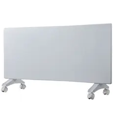
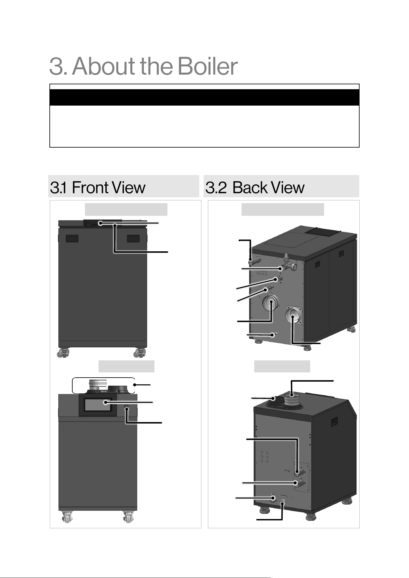
The Rinnai Commercial Boiler is a floor-standing, gas-fired boiler designed to provide heating to the
building with the ability to connect an indirect tank for DHW production.
Topics in this section
• Front View
• Back View
• Components
• Altitude
• Specifications
• Dimensions
• Included Accessories
• Optional Accessories
Figure 1
Controller
Reset
Button
Controller
Reset
Button
Vent
Connections
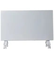
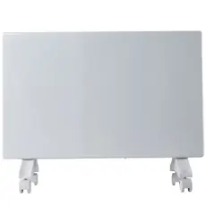
Figure 2
Condensate
Drain
Central
Heating
Supply
Central
Heating
Return
Gas
Exhaust
Air Intake
Drain
Air Intake
Exhaust
Central
Heating
Return
Central
Heating
Supply
Gas
Condensate
Drain
RCB750AN / RCB1000AN RCB750AN / RCB1000AN
RCB500AN RCB500AN
Rinnai Commercial Boiler Installation and Operation Manual 9
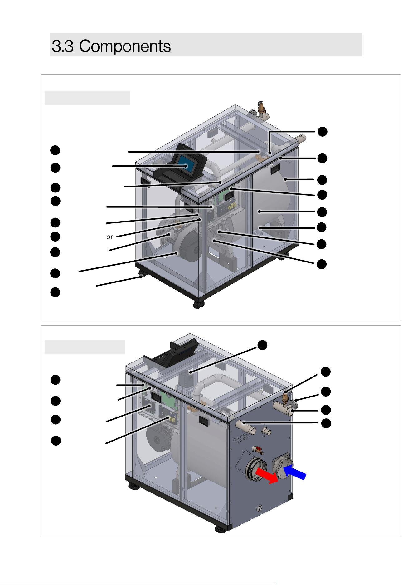
RCB1000N shown
Flue Thermistor
Return Thermistor
Spark Generator
Water Flow Sensor
Ignion Electrode
Supply Thermistor
Supply Water Pipe
Fan
Flue Pressure
Switch
High Voltage
Connecon
Burner Door
Switch
Main Control
Check Valve
7-Inch Touch
Screen Display
Exhaust
Intake
Flame Rod
(Ionizaon Probe)
16
15
12
13
14
11
8
9
10
7
4
5
6
3
1
Refer to the next page for a descripon of each component.
Figure 3
RCB1000AN shown
Heat Exchanger
Return Water Pipe
Condensate Trap
Gas Valve
Air/Gas Mixer
Low Voltage
Connecon
Cascade Module
25
21
22
19
23
24
18
Figure 4
Webserver Card/
Wi-Fi Module
Temperature &
Pressure Gauge
Pressure Relief Valve
26
27
28
Caster and leveling
pads
29
10 Rinnai Commercial Boiler Installation and Operation Manual
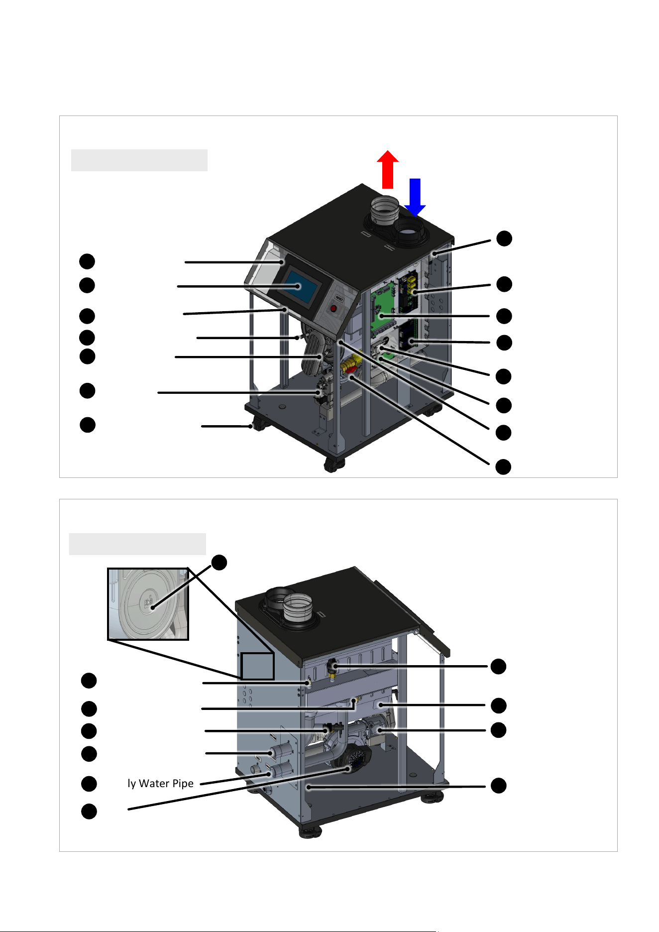
RCB500AN shown
Flue Thermistor
Automac Air Vent
Return Thermistor
Spark Generator
Water Flow Switch
Ignion Electrode
Supply Thermistor
Supply Water Pipe
Fan
Flue Pressure
Switch
High Voltage
Connecon
Burner Door
Switch
Main Control
Check Valve
7-Inch Touch
Screen Display
Exhaust
Intake
Flame Rod
(Ionizaon Probe)
16
15
12
13
14
11
8
9
10
7
4
5
6
3
2
1
Refer to the next page for a descripon of each component.
Figure 5
Thermal Fuse
Heat Exchanger
Return Water Pipe
Condensate Trap
Gas Valve
Air/Gas Mixer
Low Voltage
Connecon
Cascade Module
25
20
21
22
19
23
24
18
Figure 6
Webserver Card/
Wi-Fi Module
26
RCB500AN shown
Caster and leveling
pads
29
Rinnai Commercial Boiler Installation and Operation Manual 11
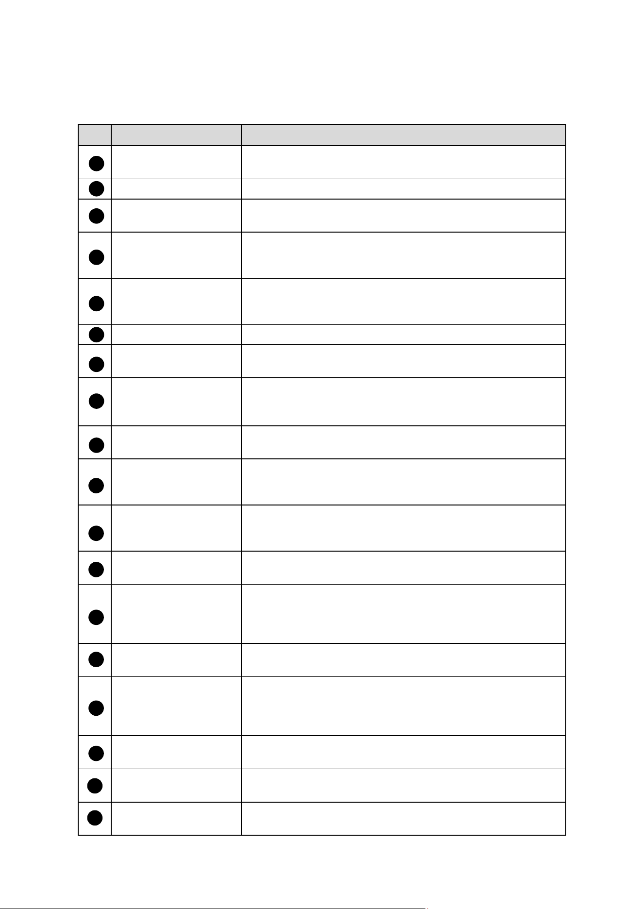
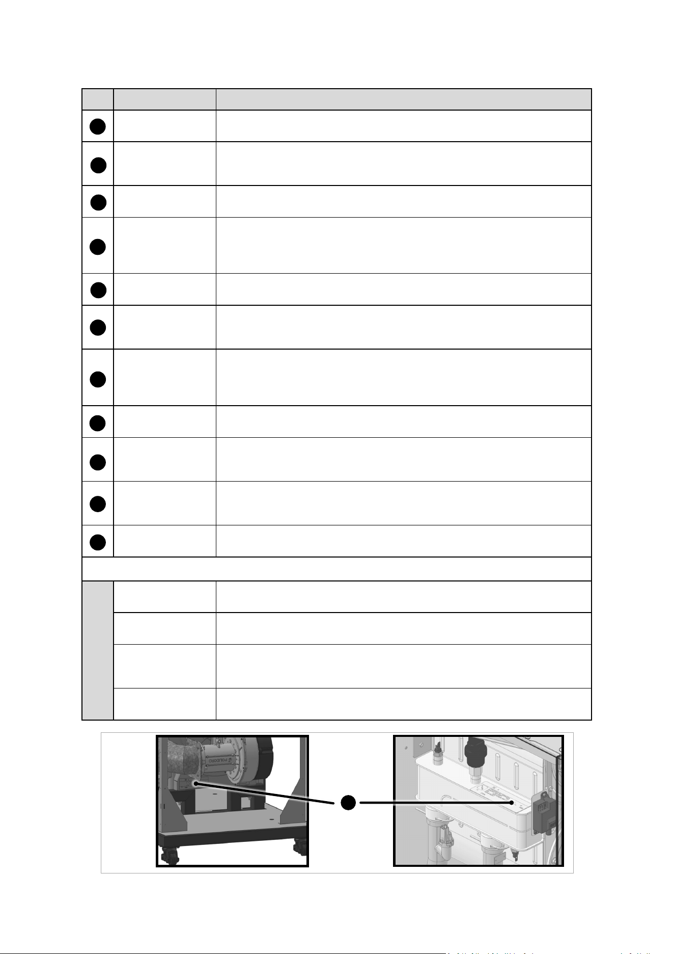
Listed below are descripons of each boiler component. Refer to the previous page for component
illustraon.
Item Name Descripon
Return Thermistor
A sensor that monitors the water temperature returning into the
boiler.
Automac Air Vent A device used to bleed the air from the heang system.
Spark Generator
Applies high voltage through the spark electrode to ignite the
burner.
Water Flow Switch
A switch that monitors water ow when boiler receives a heat
demand. This switch will disable boiler operaon in case there is
a heat demand but the ow is not detected.
Supply Thermistor
A sensor that monitors the boiler outlet water temperature. The
control will shut down the boiler in case the temperature exceeds
a certain limit.
Ignion Electrode Provides direct spark to ignite the burner.
Supply Water Pipe
1-1/2 In for RCB500AN model and 2 In for RCB750AN and
RCB1000AN models.
Fan
Pulls air and gas through the air/gas mixer. Air and gas are
pre-mixed inside of the fan and are pushed into the burner for
combuson.
High Voltage Terminal
Strip
Contains connecon points for main power supply and all pumps
power.
Flue Pressure Switch
A safety device that monitors the pressure in the vent and shuts
down the appliance in case of blockage to avoid unsafe
condions.
Flue Thermistor
A sensor that monitors the ue gas exit temperature. The control
will shut down the boiler if the ue gas temperature gets too hot
to protect the ue pipe from overheang.
Burner Door Switch
A switch that will break the control circuit, shung down the
boiler in case the burner door temperature is too high.
Main Control
The integrated controller monitors and controls the system
operaon. The controller responds to internal and external
signals and controls the fan, gas valve, spark generator, and
pumps to meet the heat demand.
Flame Rod (Ionizaon
Probe)
Detects and monitors the presence of a ame.
Check Valve
Prevents ue gas back ow into the fan in case of negave
pressure in the boiler room in a power vent installaon. The
check valve also acts as back ow preventer in a common vent
system where mulple units are cascaded.
7-Inch Touch Screen
Display
The full-color touch screen allows a user friendly interface with
the boiler control.
Air/Gas Mixer
The venturi controls the mixture of air and gas before entering
the burner for combuson.
Low Voltage Terminal
Strip
Contains connecon points for low voltage input and output
signals.
16
17
18
15
12
13
14
11
8
9
10
7
4
5
6
3
2
1
Table 2: Boiler Component Descripons
12 Rinnai Commercial Boiler Installation and Operation Manual
19
25
20
21
22
23
24
Item Name Descripon
Thermal Fuse
A safety device that will stop the boiler operaon in case of unusual
temperature rise.
Heat Exchanger
The stainless steel condensing heat exchanger is eciently designed to
maximize heat transfer through the coils while providing protecon
against ue gas corrosion.
Return Water Pipe
1-1/2 In for RCB500AN model and 2 In for RCB750AN and RCB1000AN
models.
Condensate Trap
The high eciency heat exchange produces condensate during
operaon. The condensate trap manages the condensate disposal and
the built-in oat prevents ue gases to escape through the condensate
drain.
Gas Valve
The zero governor gas valve regulates the gas ow through the venturi
based on sucon from the fan.
Cascade Module
Used to establish communicaon between boiler in a cascade system by
connecng them to each other using two conductor 18-20 AWG
shielded wire.
Webserver Card/
Wi-Fi Module
The Webserver Card/Wi-Fi Module allows the installer to remotely
monitor the system operaon, pro-acvely opmize eciency, and aid
in troubleshoong. This card also establishes the communicaon
between main control board and user interface screen.
Temperature &
Pressure Gauge
This device show the current boiler supply temperature and system
pressure.
Pressure Relief
Valve
The boiler is supplied with a 75 PSI Pressure Relieve Valve. This is a
safety device that will relief pressure and prevent unsafe operaon in
case the system pressure is too high.
Caster and
leveling pads
The boiler is had built-in caster that can facilitate moving the boiler to its
installaon locaon. Also, the leveling pads can be used to level the
boiler once it is in place.
Boiler Name Plate
The ASME name plate (Figure 7) includes the Naonal Board (NB) and
Canadian Registraon Number (CRN) numbers.
Addional Components Not Shown in Images:
Burner The metal ber and stainless steel burner uses premixed air and gas to
provide a wide range of ring rates.
Outdoor Sensor Uses the outdoor temperature to adjust the unit setpoint to provide
greater eciency.
Cascade System
Sensor
In a cascade system, the master boiler requires a system supply sensor
to operate properly. The locaon of the sensor should be downstream
of the of the boiler connecon in the main system loop.
DHW Sensor/
Aquastat
Monitors and controls the temperature of an indirect tank.
27
Table 2 (Connued): Boiler Component Descripons (Connued)
26
28
29
Figure 7
30
Boiler
Name
Plate
Rinnai Commercial Boiler Installation and Operation Manual 13
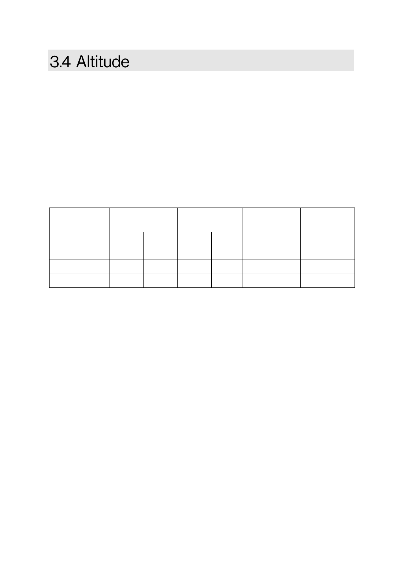
This boiler can operate from sea level up to 10,200 feet [3,109 m]. The table below represents the
de-rates for each model, gas type, and altude. For proper operaon ensure to set the control for
proper gas type and altude. Tap the setup, boiler setup page on the boiler screen for proper gas
type and altude sengs. De-rate values are based on proper combuson sengs as
recommended in this manual. For installaon above 2,000 (609 m) in Canada, follow all
applicable local codes and regulaons.
NOTE: See control secon on how to change altude seng from the control panel.
ALTITUDE VENTING:
500 model ONLY: For altudes above 2,000 (609 m), vent length is reduced to 110 (33 m).
0 - 2000
(0-609 m)
2001 - 5400
(610 -1645 m)
5401 - 7700
(1646 - 2346 m)
7701 - 10200
(2347 - 3109 m)
Model
NG LP NG LP NG LP NG LP
RCB500AN 0.0 % 0.0 % 10.0 % 10.0 % 20.0 % 20.0 % 25.0 % 25.0 %
RCB750AN 0.0 % 0.0 % 10.0 % 10.0% 15.0 % 15.0 % 20.0 % 20.0 %
RCB1000AN 0.0 % 0.0 % 0.0 % 0.0% 10.0 % 10.0 % 15.0 % 15.0 %
NOTE: The values listed on the above table are the total percentage of boiler input de-rate for each
elevaon range.
Table 3
14 Rinnai Commercial Boiler Installation and Operation Manual
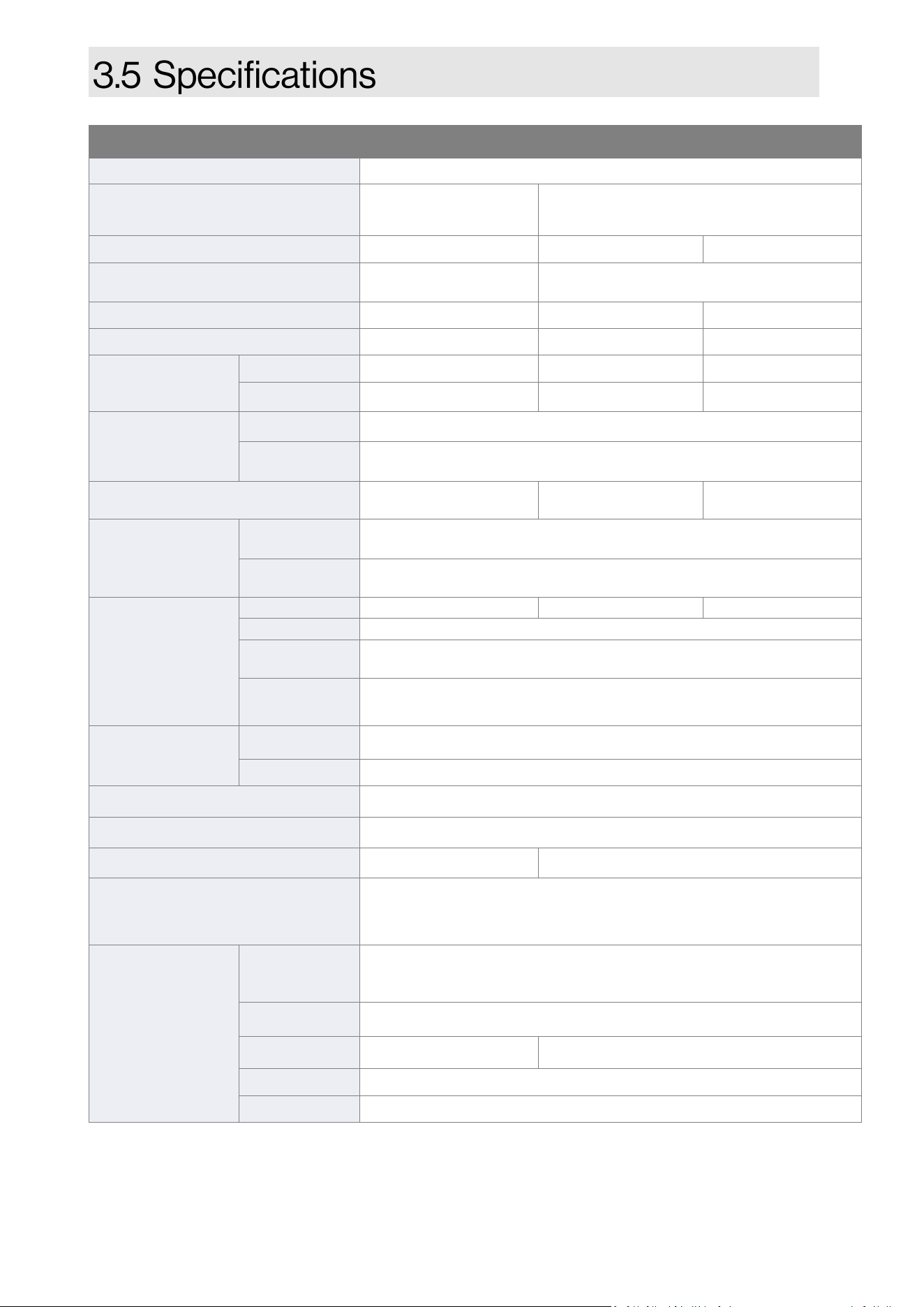
1 Maximum gas supply pressure must not exceed the value specied by the manufacturer.
Rinnai products are connually being updated and improved; therefore, specicaons are subject to
change without prior noce.
2 500 model ONLY: For altudes above 2,000 (609 m), vent length is reduced to 110 (33 m).
Table 4: Specicaons
Model RCB500AN RCB750AN RCB1000AN
Ignion System Direct Electronic Ignion
Dimensions (Appliance) - In. (mm) -
w, h, d
21.75 x 39.5 x 30.75
(550 x 1004 x 781)
28.5 x 44.5 x 51.75
(723 x 1127 x 1312)
Weight (Appliance) 243 lb (110 kg) 525 lb (238 kg) 567 lb (257 kg)
Dimensions (Shipping) - In. (mm) -
w, h, d
30 x 48 x 36
(770 x 1220 x 910)
38 x 57 x 60
(970 x 1450 x 1530)
Weight (Shipping) 300 lb (136 kg) 591 lb (268 kg) 633 lb (287 kg)
Heat Exchanger Surface Area 36.8 sq 60.9 sq 75.4 sq
Gas
Consumpon
(Btu/h)
Minimum 50,000 75,000 99,000
Maximum 500,000 750,000 999,000
Temperature
Seng
CH (Minimum - Maximum) 86°F - 180°F (30°C - 82°C)
Indirect
Tank (DHW)
104°F - 176°F (40°C - 80°C)
Water Content 2.7 gal (10.1 lt) 6.6 gal (24.8 lt) 8.1 gal (30.6 lt)
Water Pressure
CH
Minimum: 14.5 PSI (1 bar)
Maximum Allowable Water Pressure (MAWP): 160 PSI (1103 kPa)
PRV 75 PSI (5.2 bar) (Pressure Relieve Valve included with system)
Electrical Data
Normal 350 W 484 W 605 W
Standby 10 W
Max
Current
20 Amps
Fuse
Main controller: 2 x 6.3 Amps
Each Pump (Boiler, CH, DHW): 5 Amps
Gas
Supply Pressure
1
Natural Gas 3.5 in. - 10.5 in. wc (0.87 - 2.61 kPa)
Propane 8.0 in. - 13.5 in. wc (1.99 - 3.36 kPa)
Electric Connecons AC 120 Volts, 60 Hz
Cercaons ANSI Z21.13, CSA 4.9, ASME
Canada CRN Y6325.2C R5402.5C
Warranty
Heat Exchanger: 10 Years. All Other Parts & Components: 1 Year.
Reasonable Labor: 1 Year. See the “Rinnai Commercial Boiler
Warranty” for Complete Details
Venng
45° elbow is
equivalent to 3
(1 m).
90° elbow is
equivalent to 6
(2 m).
Opons:
• Direct Vent
• Non-Direct Vent (Room Air)
Materials
PVC, CPVC, PP and Stainless Steel
Vent Size
4 in. PVC/CPVC 6 in. PVC/CPVC
Exhaust
2
Vent Run (Min-Max): 10 (3 m) - 140 (43 m)
Intake
2
Vent Run (Min-Max): 0 (0 m) - 140 (43 m)
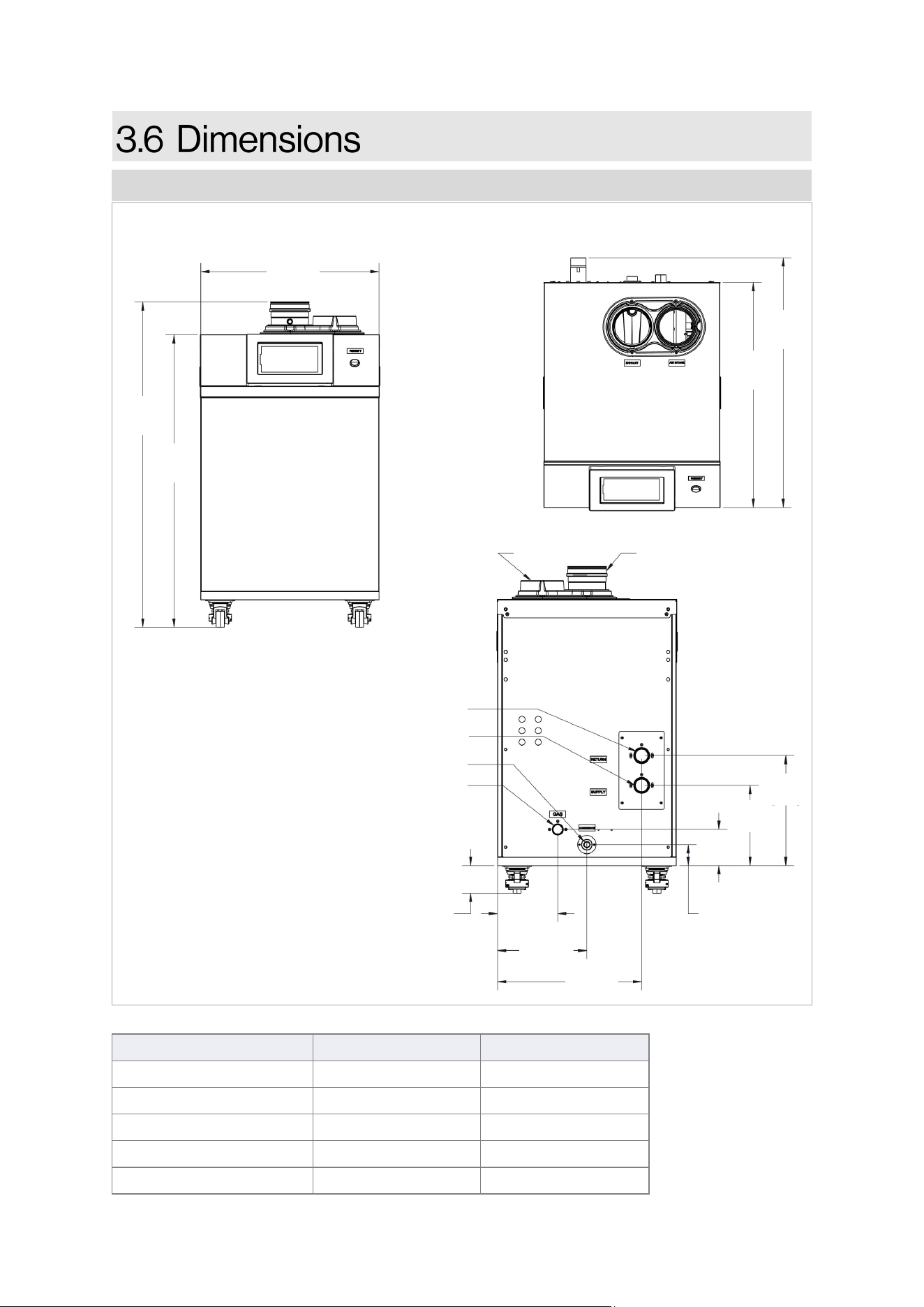
Rinnai Commercial Boiler Installation and Operation Manual 15
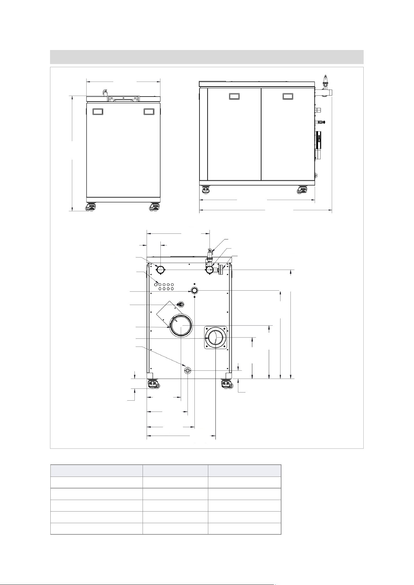
Measurements: in. [mm]
Connection Connection Size Minimum Pipe Size
Gas 1 in. NPT 1 in.
CH In (CH Return) 1-1/2 in. NPT 1-1/2 in.
CH Out (CH Supply) 1-1/2 in. NPT 1-1/2 in.
Condensate Drain 1 in. NPT 3/4 in.
Venting (Intake & Exhaust) 4 in. PVC/CPVC 4 in.
Dimensions: RCB500AN MODEL
Table 5
TOP
30-3/4
[781]
27-3/4
[704]
BACK
AIR INTAKE
EXHAUST
WATER SUPPLY
WATER RETURN
CONDENSATE DRAIN
GAS
7-1/4
[185]
10-3/4
[275]
17-1/2
[443]
2-1/2
[64]
4-3/8
[111]
13-5/16
[338]
9-3/4
[247]
3-3/8 - REF
[85] - REF
Measurements: in. [mm]
FRONT
39-1/2
[1004]
35-1/2
[903]
21-3/4
[550]
Figure 8
AIR INTAKE
16 Rinnai Commercial Boiler Installation and Operation Manual
Connection Connection Size Minimum Pipe Size
Gas 1-1/4 in. NPT 1-1/4 in.
CH In (CH Return) 2 in. NPT 2 in.
CH Out (CH Supply) 2 in. NPT 2 in.
Condensate Drain 1 in. NPT 3/4 in.
Venting (Intake & Exhaust) 6 in. PVC/CPVC 6 in.
Dimensions: RCB750AN & RCB1000AN MODELS
Table 6
SIDE
51-3/4
[1312]
45
[1143]
FRONT
44-1/2
[1127]
28-1/2
[723]
CONDENSATE DRAIN
BACK
AIR INTAKE
EXHAUST
WATER SUPPLY
WATER RETURN
ELECTRICAL
KNOCKOUTS
GAS
DRAIN
PRESSURE/TEMP GAUGE
3-3/8 - REF
[85] - REF
75 PSI PRV
21
[536]
4-5/8
[118]
11-1/2
[292]
3
[70]
17-3/4
[452]
29-5/8
[751]
36-1/2
[927]
13-3/4
[351]
13-3/4
[348]
16
[406]
23
[586]
Figure 9
Rinnai Commercial Boiler Installation and Operation Manual 17
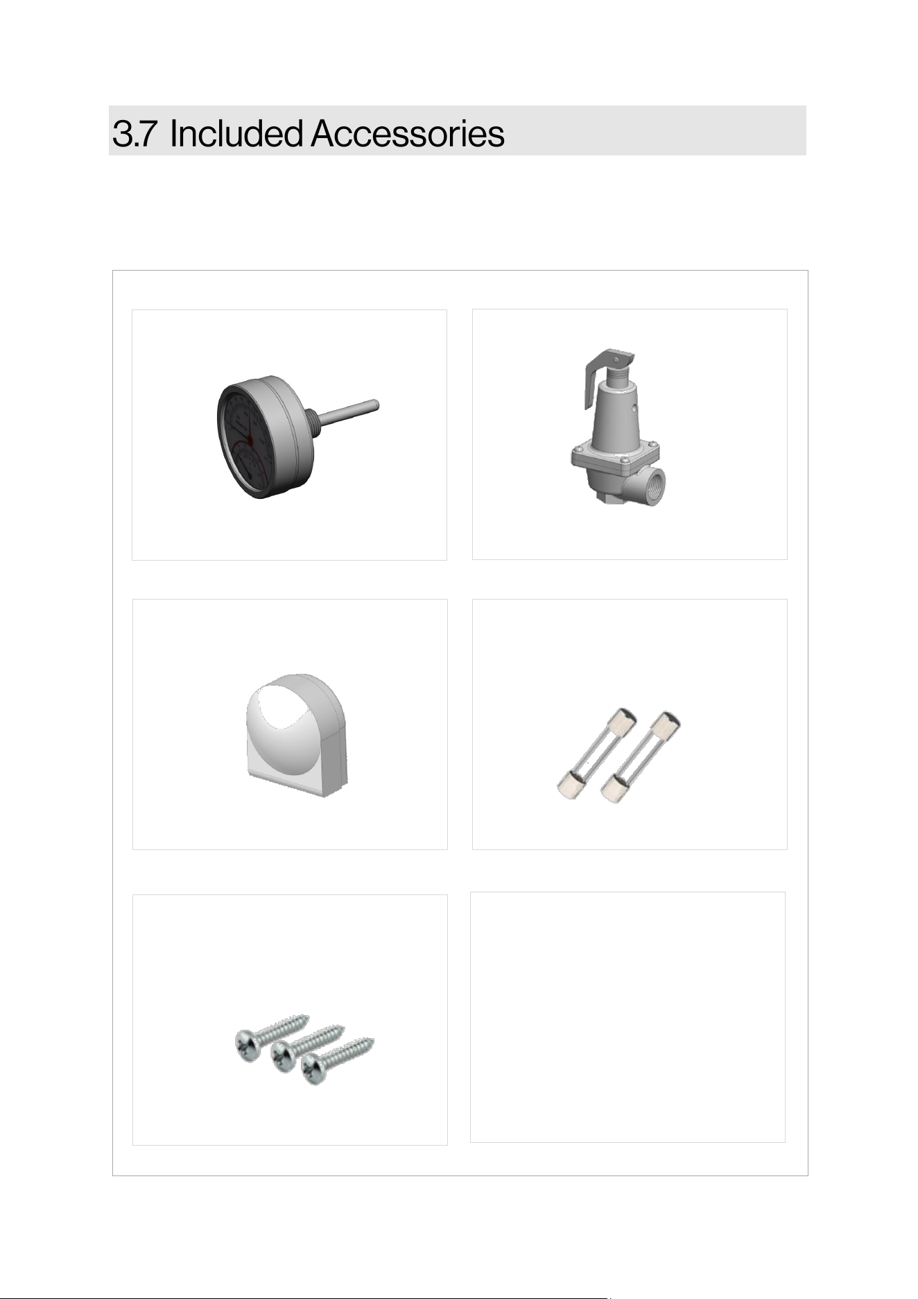
Carefully unpack your boiler system and verify the following contents are included. If any items are
damaged or missing, contact your local dealer/distributor. Do not aempt to use any item that
appears damaged.
• Installaon and Operaon Manual
(this manual)
• User Manual
• Warranty Card
• Addional technical literature
included inside product box
• CSD-1 Form
DOCUMENTATION
TEMPERATURE & PRESSURE
GAUGE
PART #: 803000092
PRESSURE RELIEF VALVE, 75 PSI
OUTDOOR TEMPERATURE
SENSOR
PART #: 805000097
PART #: 807000224
Figure 10
SPARE FUSES - 2 X 6.3 A
(LOCATED INSIDE OF MAIN
CONTROL COVER)
INTAKE PIPE SCREWS (QTY 3)
4.8 X 25 MM SS PANHEAD PH2
(TAPPED TO INTAKE ADAPTER)
PART #: 803000079
PART #: 809000304
18 Rinnai Commercial Boiler Installation and Operation Manual
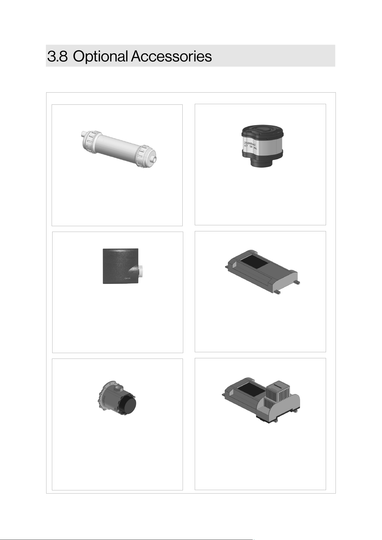
The following oponal accessories are available for the Rinnai Commercial Boiler.
Neutralizes the condensate
generated by the boiler.
CONDENSATE NEUTRALIZER
PART #: 804000074
Filters and eliminates debris (> 0.5 mm)
from entering the combuson chamber
for indirect venng (room air) piping.
AIR INLET FILTER
PART #: 803000050
In a cascade system the Master boiler
requires a system supply sensor in
order to operate properly. The locaon
of the sensor should be downstream of
the of the boiler connecon in the
main system loop.
CASCADE SYSTEM SENSOR
PART #: 803000051
GAS CONVERSION KIT
Converts the boiler gas type.
PART #: 803000083 - 500 NG
PART #: 803000084 - 500 PROPANE
PART #: 803000085 - 750 NG
PART #: 803000086 - 750 PROPANE
PART #: 803000087 - 1000 NG
PART #: 803000088 - 1000 PROPANE
Connued on next page
500 MODEL ONLY
To establish boiler communicaon with
Building Management System (BMS)
through BACnet.
BACNET ADAPTER
PART #: 803000078
To establish boiler communicaon with
Building Management System (BMS)
through LonWorks.
BACNET ADAPTER WITH LONWORKS
PART #: 803000080
Figure 11
Rinnai Commercial Boiler Installation and Operation Manual 19
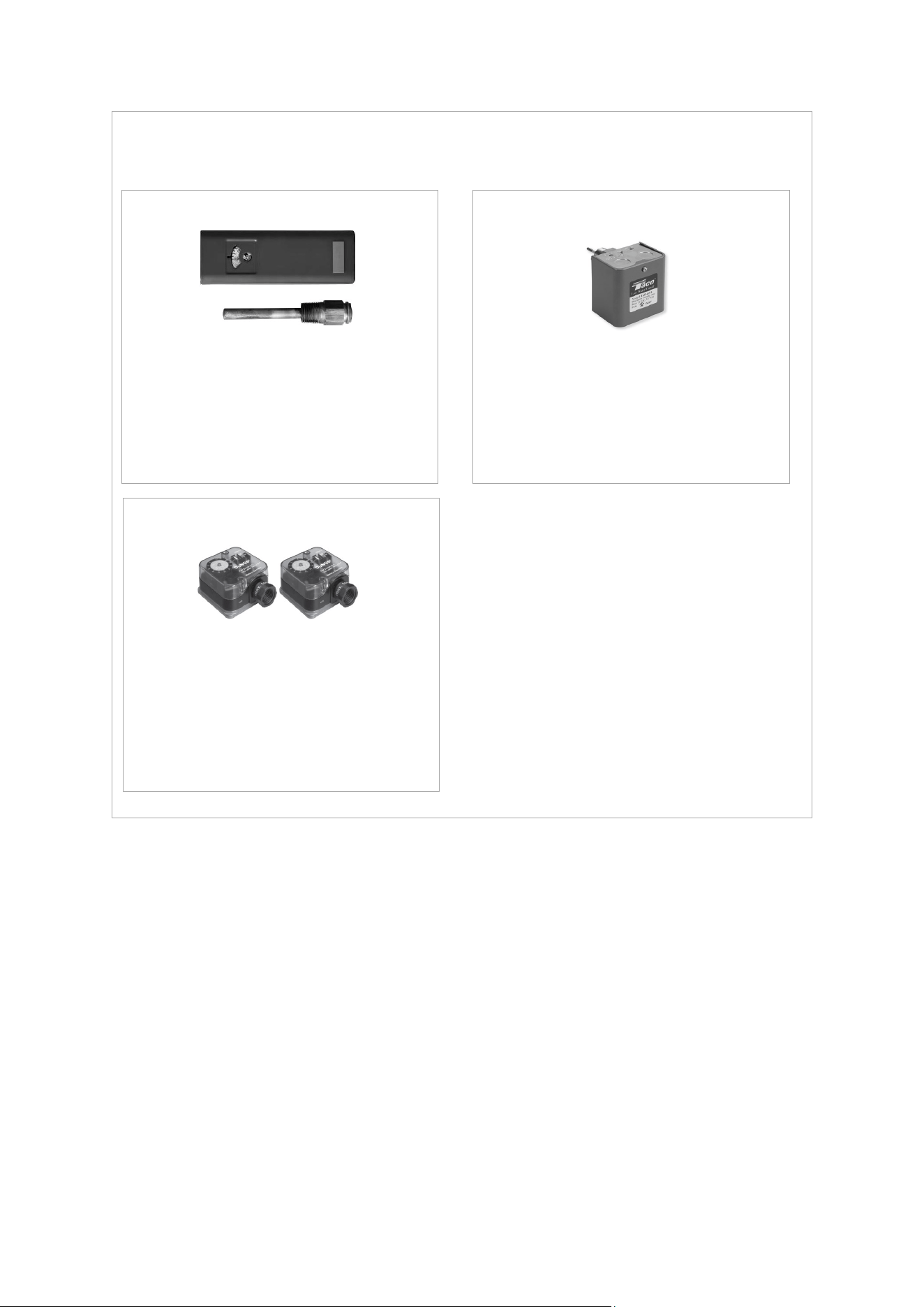
Oponal Accessories (Connued)
This device limits the boiler supply
temperature and will shut the boiler down
in case of high temperature. It has a
manual reset funcon and complies with
CSD-1 requirements.
WATER TEMPERATURE HIGH LIMIT
PART #: 804000089
This device detects system water level
and will shut the boiler down in case the
water level is low. It has a manual reset
and complies with CSD-1 requirements.
LOW WATER CUT-OFF (LWCO)
PART #: 803000090
These devices monitor gas pressure
and will shut the boiler down in case
the gas pressure is too low or too high.
They have a manual reset funcon and
comply with CSD-1 requirements.
HIGH & LOW GAS PRESSURE SWITCHES
PART #: 803000091
Figure 11 A
20 Rinnai Commercial Boiler Installation and Operation Manual
THIS SECTION IS INTENDED
FOR THE INSTALLER
Installer qualicaons: A trained and qualied
professional must install the appliance,
inspect it, and leak test the boiler before use.
The warranty will be voided due to any
improper installaon. The trained and
qualied professional should have skills such
as: Gas sizing; Connecng gas lines, water
lines, valves, and electricity; Knowledge of
applicable naonal, state, and local codes;
Installing venng through a wall or roof; and
training in installaon of condensing boilers.
Topics in this secon
• Installaon Guidelines
• What You Will Need
• Choose an Installaon Locaon
• Prepare the Boiler
• Fill the Condensate Collector
• This boiler is cered for installaon in
residenal and commercial applicaons.
• This boiler is suitable for combinaon
water heang through an indirect tank
and central heang.
• The installaon must conform with local
codes or, in the absence of local codes,
with the Naonal Fuel Gas Code, ANSI
Z223.1/NFPA 54, or the Natural Gas and
Propane Installaon Code, CSA B149.1. If
installed in a manufactured home, the
installaon must conform with the
Manufactured Home Construcon and
Safety Standard, Title 24 CFR, Part 3280
and/or CAN/SCA Z240 MH Series, Mobile
Homes.
• The appliance, when installed, must be
electrically grounded in accordance with
local codes or, in the absence of local
codes, with the Naonal Electrical Code,
ANSI/NFPA 70, or the Canadian
Electrical Code, CSA C22.1.
• The appliance and its main gas valve
must be disconnected from the gas
supply piping system during any
pressure tesng of that system at test
pressures in excess of 1/2 psi (3.5 kPa)
(13.84 in W.C.). For system tesng at
pressures less than or equal to 1/2 psi
(3.5 kPa) (13.84 in W.C.) the appliance
must be isolated from the gas supply
piping by closing its individual manual
shuto valve.
• You must follow the installaon
instrucons and those in secon
“5. Venng” for adequate combuson
air and exhaust.
• Should overheang occur or the gas
supply fail to shut o, turn o the
manual gas control valve to the
appliance.
• Combuson air must be free of
chemicals, such as chlorine or bleach,
that produce fumes. These fumes can
damage components and reduce the life
of your appliance.
• Where required by the authority having
jurisdicon, the installaon must comply
with the Standard for Controls and
Safety Devices for Automacally Fired
Boilers, ANSI/ASME CSD-1.
Rinnai Commercial Boiler Installation and Operation Manual 21
DO NOT install the boiler in an area
where water leakage of the unit or
connecons will result in damage to
the area adjacent to the appliance
or to lower oors of the structure.
When such locaons cannot be
avoided, it is required that a
suitable drain pan, adequately
drained, be installed under the
boiler. The pan must not restrict
combuson air ow.
DO NOT install the boiler in an area
with negave air pressure.
DO NOT obstruct the ow of
combuson and venlaon air.
DO NOT use substute parts that
are not authorized for this boiler.
DO NOT install the boiler on
carpeng.
DO NOT install boiler outdoors.
DO NOT
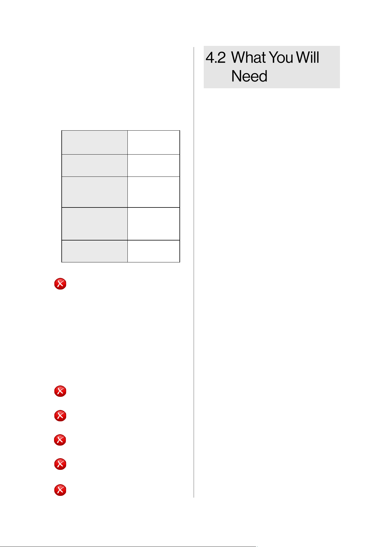
Gather the recommended tools and parts
before starng installaon.
Items Needed
• Boiler Pump
• Pressure relief valve for domesc hot
water (150 PSI / 10.3 Bar)
(as necessary, if using a separate
indirect tank).
• Pressure/Temperature Gauge
Note: When aaching the pressure/
temperature gauge, please comply
with applicable codes and the ASME
standard.
• Low loss header or closely spaced tee
• Expansion tank for a closed heang
system
• Air separator
• Standard tools for central heang, gas
ng, plumbing and electrical wiring.
• Digital manometer
• Combuson analyzer (intended for use
with condensing boilers)
• Digital mulmeter capable of reading
microamps
• pH digital meter or test strips
• For wall mounng bracket installaon:
− Level
− Screws (use appropriate screws for
type of wall construcon)
Other Items You May Need
• Pallet Jack, Forkli, or Hoist
• Ensure the wall is of sucient
strength to support the weight of the
boiler, piping and any other
components needed for installaon;
if it is not, please reinforce the wall as
appropriate.
• Operang limits of the boiler:
Maximum boiler set
point temperature:
180°F (82°C)
Maximum operang
pressure:
160 psi (11 bar)
Maximum allowable
working
temperature ASME:
210°F (99°C)
Maximum allowable
working pressure
ASME:
160 psi (11 bar)
Pressure Relief Valve
(shipped with unit):
75 psi (5.2 bar)
Table 7
22 Rinnai Commercial Boiler Installation and Operation Manual
Consideraon of care for your boiler should
include evaluaon of water quality.
• The water must be potable, free of
corrosive chemicals, sand, dirt, or other
contaminants.
• It is up to the installer to ensure the water
does not contain corrosive chemicals or
elements that can aect or damage the
boiler.
• Water that contains chemicals exceeding
the levels below can damage the boiler.
• The pH level must fall between 6.5 and
8.5.
• Total water hardness must fall between 5
and 12 grains per gallon.
• When water hardness is higher than
12 grains per gallon consult local
water treatment companies.
• Chloride concentraon must be less than
150 ppm (mg/l)
• Do not ll appliance to work with
water containing chlorides in excess
of 150 ppm (mg/l).
• Using chlorinated fresh water should
be acceptable as levels are typically
less than 5 ppm (mg/L).
• Do not connect the appliance to
directly heat swimming pool or spa
water.
• Total Dissolved Solids (TSD) must be
between 100 and 350 ppm (mg/l).
• Total dissolved solids are minerals,
salts, metals, and charged parcles
that are dissolved in water.
When choosing an installaon locaon, you
must ensure that clearances will be met and
that the vent length will be within required
limits. Consider the installaon
environment, water quality, and need for
freeze protecon. Requirements for the gas
line, water lines, electrical connecon, and
condensate disposal can be found in their
respecve installaon secons in this
manual.
This secon provides informaon on the
importance of water quality to the Rinnai
Condensing Boiler. The informaon is
intended to serve as general guidelines only
and is not a complete list of water quality
guidelines.
• The greater the amounts of TDS
present, the higher the corrosion
potenal due to increased
conducvity in the water.
• If using soened water to ll the
appliance, it is sll possible to have
high TDS. This water can be
corrosive. Consult local water
treatment companies for other
treatment soluons to reduce this
aect.
• Unsuitable heang system water can
cause the formaon of scale or sludge,
which aects system eciency. It can
also cause corrosion and reduce life of
the heat exchanger. It is crical to
monitor pH, hardness level, chlorides,
and TDS to prolong the life of the
appliance.
• Never use water that has been treated by
a reverse osmosis, deionized, or dislled
water to soen the water to ll the
heang system.
• Connual fresh makeup water will
reduce the life of the appliance. The
addion of oxygen carried in by the make
up water can cause internal corrosion in
the system.
• When using a make up water, It is
recommended to install a water meter to
monitor the amount of water being
introduced into the system. The total
annual make up water should not exceed
5% of the total system water volume.
• Oxygen permeable or rubber tubing is
not permied in the heang system
unless it is separated from the boiler by a
plate heat exchanger.
• Thoroughly ush the system prior to
lling. While ushing, isolate the boiler.
• Do not introduce any system cleaner into
the boiler. Flush the system thoroughly
to remove all system cleaner before
lling the boiler with water.
• When freeze protecon of the heang
system is desired, use Rinnai-approved
anfreezes.
Rinnai Commercial Boiler Installation and Operation Manual 23
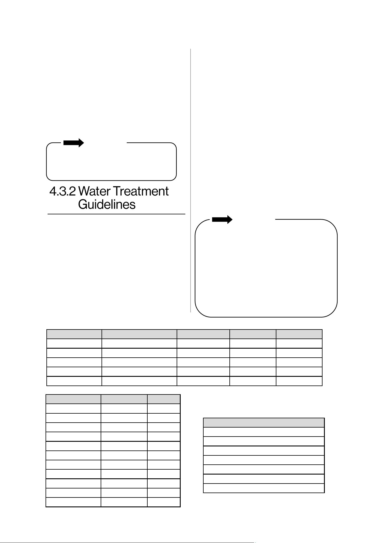
Producers Fernox Sennel Son ADEY
Inhibitors Protector F1/Alphi 11 X100, X500 Sion 212 MCI+
Noise Reducer X200
Universal Cleaner Restorer X300
Sludge Remover Protector F1, Cleaner F3 X400 Sion 212
Tightness Leaker Sealer F4
Treatment Type Prevenve Curave
Protector F1 X
Cleaner F3 X X
X100 X
X200 X
X300 X
X400 X
X500 X
Alphi 11 X
Leaker Sealer F4 X
Sion 212 X
MCI+ X
Table 9: Corrosion/Scale Treatment Types
Consult the glycol manufacturer for details
on the suggested mix of glycol and water for
the desired freeze protecon level and the de
-rate eect it will have on the boiler output.
NEVER use automove anfreeze. Use ONLY
inhibited propylene glycol soluons, which
are specically formulated for hydronic
heang system. Ethylene glycol is toxic and
can aack gaskets and seals used in hydronic
heang system. The allowed maximum
concentraon is 40 percent.
• Black oxide sludge (magnete - Fe304)
forms as a result of connuous electrolyc
corrosion in any system unprotected by an
inhibitor.
• Iron oxide (Fe203) (red oxide sludge) is
produced during oxygenaon. Scale
deposit is made up of lime scale contained
in most distributed water that seles over
the warmest surfaces of the system.
Sludge and scale do mix together and are
the cause of many eld problems on
heang applicaons. The presence of
these substances indicate that standard
precauons have not been implemented
and may void warranty.
• The chemical compability of several
products for the treatment of heang
water equipment has been tested on this
boiler’s heat exchanger.
• Rinnai recommends using the system
cleaners, corrosion/scale inhibitors in the
table below.
• Keep the system free of impuries,
construcon dust, sand, copper dust,
grease, carbon deposits, and welding ux
residue before and during boiler
assembly. Rinse the old system with clear
water mixed with a highly concentrated
rinse agent.
• More generally, it is advised to
implement any procedure necessary to
prevent or treat contaminaon.
Table 8: Corrosion/Scale Inhibitors and Recommended Suppliers
IMPORTANT
Replacement of components due to
water quality damage is not covered by
the warranty.
Approved System Anfreezes
Chem Frost 100%
Fernox Alphi 11
Hall-Chem Solar II
Noble Noburst AL
Rechochem Recofreeze AL
Rhomar RhoGar Mul-Metal (AL safe)
Sennel X500
Table 10: Approved System Anfreezes
IMPORTANT
• If replacing a boiler, add system cleaners
while the old boiler is installed and
operate the old boiler for heang for
several days to most eecvely clean the
system.
• The Rinnai boiler must be closed o
(valved o) from the rest of the system,
or not connected, while cleaners are in
the system.
• When cleaning is complete, drain the
system and then ush with clean water to
remove any sediment.
24 Rinnai Commercial Boiler Installation and Operation Manual
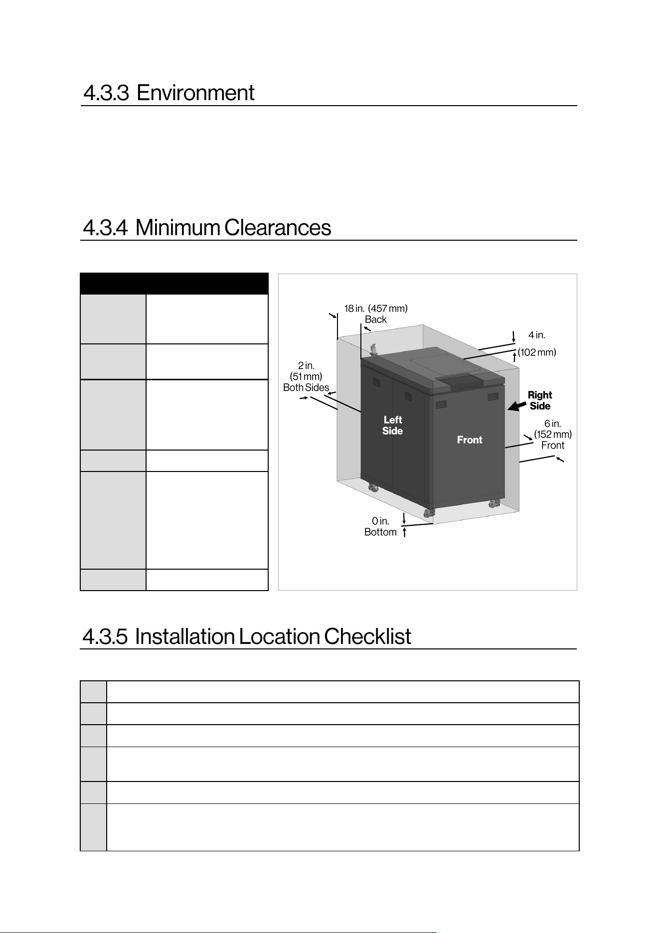
Use this checklist to ensure you have selected the correct locaon for the boiler.
Air surrounding the boiler, venng, and vent terminaon(s) is used for combuson and must be free
of any compounds that cause corrosion of internal components. These include corrosive compounds
that are found in aerosol sprays, detergents, bleaches, cleaning solvents, oil based paints/varnishes,
and refrigerants. The air in beauty shops, dry cleaning stores, photo processing labs, and storage
areas for pool supplies oen contains these compounds. The boiler, venng, and vent terminaon(s)
should not be installed in any areas where the air may contain these corrosive compounds.
□
The boiler is not exposed to corrosive compounds in the air.
□
The boiler locaon complies with the required clearances.
□
The planned combuson air and exhaust terminaon locaons meet the required clearances.
□
The water supply does not contain chemicals or exceed total hardness that will damage the
heat exchanger.
□
Ensure boiler is properly connected and grounded from 120 VAC, 60 Hz power source .
□
The installaon must conform with local codes or, in the absence of local codes, with the
Naonal Fuel Gas Code, ANSI Z223.1/NFPA 54, or the Natural Gas and Propane Installaon
Code, CSA B149.1.
Table 11: Minimum Clearances
Figure 12
Locaon Clearance
Top 4 in. (102 mm)
0 in. from vent
components
Boom
(Ground)
0 in. (0 mm)
Front 6 in. (152 mm)
Clearance for servicing
is 24 in. (610 mm) in
front of boiler
Back 18 in. (457 mm).
Sides
(Le and
Right)
2 in. (51 mm)
Clearance for servicing
is 24 in. (610 mm) on
the right side and 12
in. (305 mm) on the
le side.
Vent 0 in. (0 mm)
This image is not to scale and is for illustraon
purposes only.
Rinnai Commercial Boiler Installation and Operation Manual 25
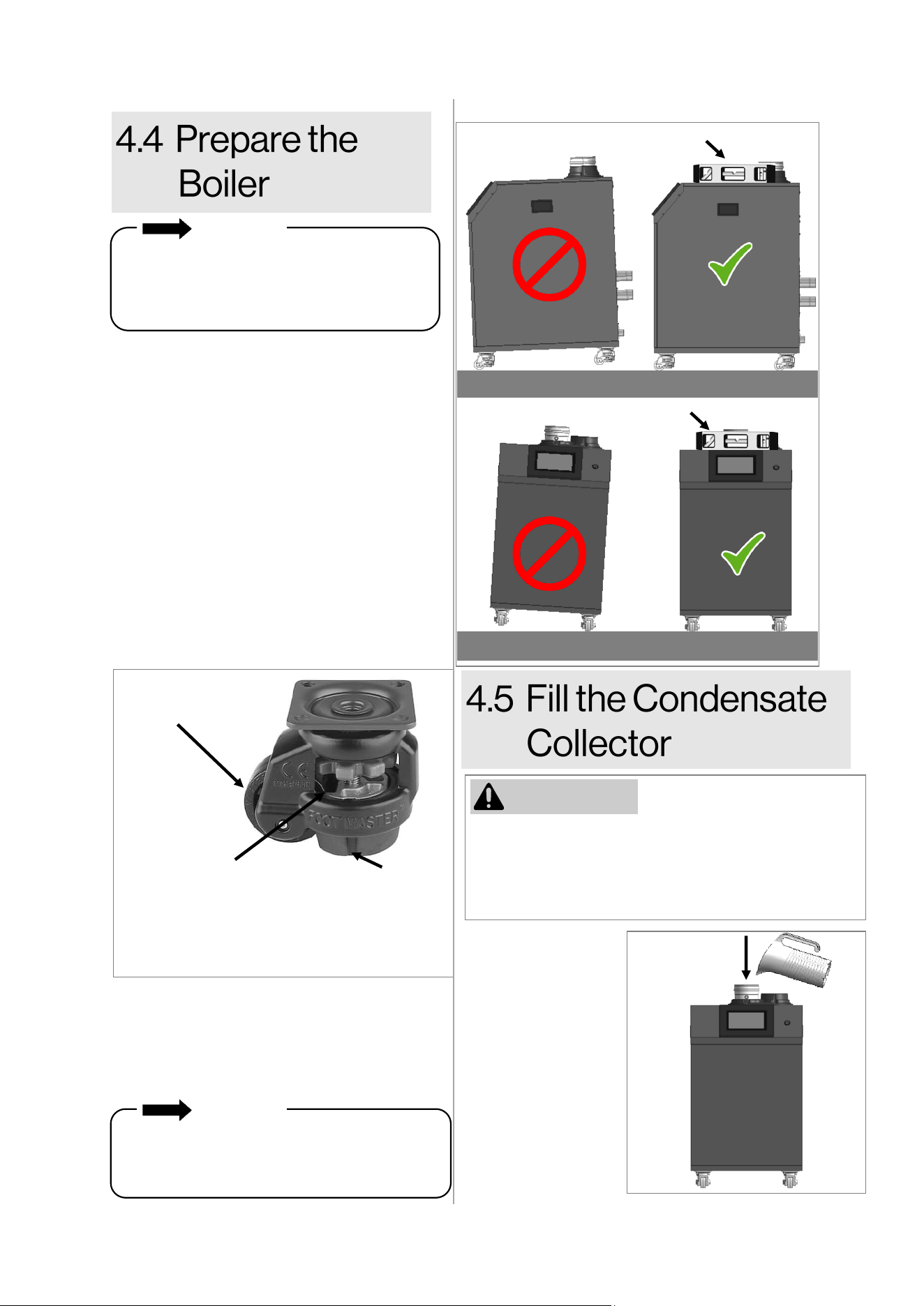
Remove the boiler from the shipping
packaging and move it to the installation
location. NOTE: The boiler is equipped with
casters /leveling feet that makes it easy to
maneuver the boiler.
When moving the boiler, the leveling pads
should be raised to allow the wheels to touch
the ground and roll.
When the boiler is at its final installation
location, the leveling pads should be lowered
to ensure the boiler is stationary. The leveling
pads can be used to ensure the boiler is
leveled properly.
The condensate
collector must be
filled with water
prior to installing the
vent system.
Pour approximately
10 ounces (1.25
cups) of water
directly into the
boiler’s exhaust
port.
1.
Instructions:
Before operation of the boiler, the condensate
collector must be filled with water. This is to prevent
the potential of exhaust gasses from entering the
building. Failure to fill the condensate collector could
result in severe personal injury or death.
Figure 15
WARNING
IMPORTANT
When installing the boiler, the boiler must be
level to ensure proper flow of condensation
inside the boiler heat exchanger. Boiler must
be level from side-to-side and front-to-back.
Exhaust
Port
Wheel
Thumb Wheel
- Turn the thumb wheel to the
le to raise the leveling pad.
- Turn the thumb wheel to the
right to lower the leveling pad.
Leveling Pad
FLOOR
FLOOR
Level
Level
Figure 13
Figure 14
In order for condensation to drain properly
from the boiler collection system, the boiler
must be properly leveled. Use a level to verify
that the boiler is level from side-to-side and
front-to-back.
2.
The boiler must be installed in an upright and
level position. Do not install the boiler upside
down or on its side.
IMPORTANT
26 Rinnai Commercial Boiler Installation and Operation Manual
• The boiler is rated ANSI Z21.13
Category IV (pressurized vent, likely to
form condensate in the vent) and
requires a special vent system
designed for pressurized venng.
• This boiler can be installed in direct
vent or non-direct (room air) vent
applicaons.
• When installed as Direct Vent, refer to
the following secon for a complete
list of approved vent manufacturers
and products: “5.5.1 Direct Vent:
Approved Vent Manufacturers and
Products.”
• Exhaust must be directly vented to
the outside. Combuson air can be
provided from outside (Direct Vent) or
from room air (Non-Direct Vent).
• If using room air (non-direct vent) for
combuson, ensure the required
volume of indoor air is available
according to the Naonal Fuel Gas
Code, ANSI Z223.1/NFPA 54.
• Avoid dips or sags in horizontal vent
runs by installing supports per the
vent manufacturer’s instrucons.
• Support horizontal vent runs every 4
(1.2 m) and all vercal vent runs
every 6 (1.83 m) or as per vent
manufacturer’s instrucons or local
code requirements.
Topics in this secon
• Guidelines
• Venng Installaon Sequence
• Terminaon Consideraons
• PVC Venng Safety Switch
• Venng Opons
• Venng should be as direct as possible with
a minimum number of pipe ngs.
• For manufactured vent systems, vent
connecons must be rmly pressed
together so that the connecons form an
air ght seal. Follow the venng
manufacturer’s instrucons.
• Refer to the Schedule 40 PVC/CPVC
manufacturer for appropriate ngs,
solvents or joining methods.
• If venng reassembly is needed, follow the
steps for installing the venng in the
following secons. Make certain that the
vent piping and seals are not damaged.
Only use sealants, primers, or glues that are
approved for the vent material in use.
• Refer to the instrucons of the vent system
manufacturer for component assembly
instrucons.
• If the vent system is to be enclosed, it is
suggested that the design of the enclosure
shall permit inspecon of the vent system.
The design of such enclosure shall be
deemed acceptable by the installer or the
local inspector.
• Any issues resulng from improper vent
installaon will not be covered by warranty.
• DO NOT use cellular core PVC/CPVC.
• DO NOT use Radel, ABS, or galvanized
material to vent this appliance.
• DO NOT cover non-metallic vent pipe
and ngs with thermal insulaon.
• DO NOT combine vent components
from dierent manufacturers.
• Vent diameter cannot be less than 4 in.
for RCB500AN model and less than 6 in.
for RCB750AN and RCB1000AN models.
• DO NOT connect the venng system
with an exisng vent or chimney.
• DO NOT common vent with the vent
pipe of any other manufacturer’s boiler
or appliance.
WARNING
Rinnai Commercial Boiler Installation and Operation Manual 27
1. Determine the terminaon method - horizontal
or vercal, concentric or twin pipes
terminaons, etc.
2. Determine proper locaon for wall or roof
penetraon for each terminaon.
3. Install terminaon assembly as described in this
manual or in the vent manufacturer’s
installaon instrucons.
4. Install intake and exhaust piping from boiler to
terminaon.
5. Slope horizontal exhaust run towards the boiler
1/4 in per foot. DO NOT slope combuson air
pipe towards boiler.
6. Install vent supports and brackets allowing for
movement from expansion, or as per vent
manufacturer’s instrucons or local code
requirements.
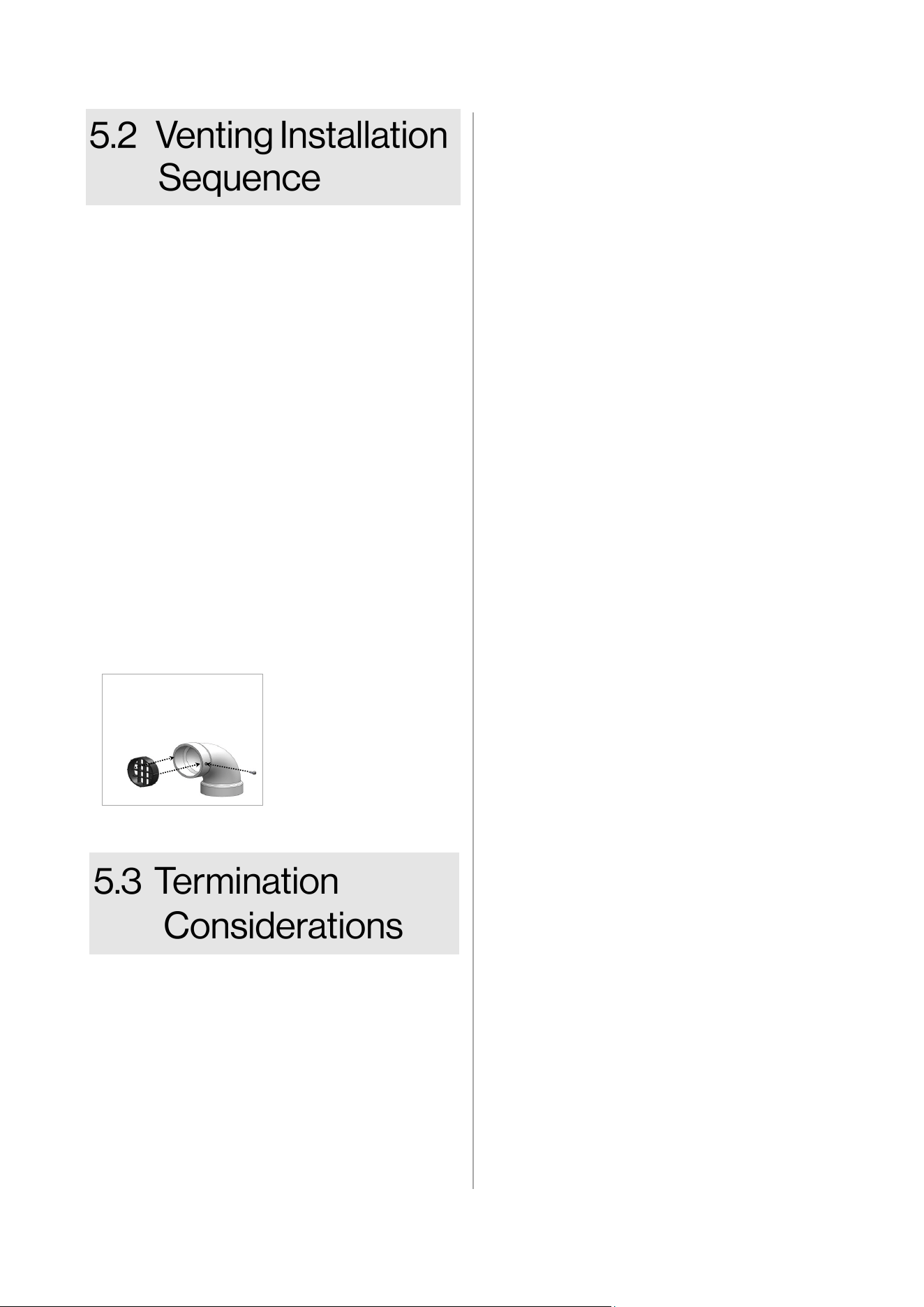
7. (Oponal step) Install vent screen or room air
lter (not included with purchase) at intake and
exhaust terminaons as illustrated below.
Check to determine whether local codes
supersede the following clearances:
• Avoid terminaon locaons near a dryer
vent.
• Avoid terminaon locaons near
commercial cooking exhaust.
• Avoid terminaon locaons near any air
inlets.
• You must install a vent terminaon at least
12 in. above the ground or ancipated snow
level.
Vent Screen
• Press vent screen
inside of terminaon
piece/elbow.
• Secure vent screen to
the terminaon
piece/elbow with
screw.
The vent for this appliance shall not
terminate:
• Over public walkways.
• Near sot vents or crawl space vents
or other area where condensate or
vapor could create a nuisance or
hazard or cause property damage.
• Where condensate or vapor could
cause damage or could be detrimental
to the operaon of regulators
pressure relief valves, or other
equipment.
Listed below are important consideraons
for locang vent terminaon under a sot
(venlated or unvenlated or eave vent; or
to a deck or porch):
• Do not install vent terminaon under
a sot vent such that exhaust can
enter the sot vent.
• Install vent terminaon such that
exhaust and rising moisture will not
collect under eaves. Discoloraon to
the exterior of the building could
occur if installed too close.
• Do not install the vent terminaon too
close under the sot where it could
present recirculaon of exhaust gases
back into the combuson air intake of
the terminaon.
Horizontal porons of the venng system
shall be supported to prevent sagging:
• For category IV boilers, have
horizontal runs sloping upwards not
less than 1/4 in. per foot (21 mm/m)
from the boiler to the vent terminal;
• For category IV boilers, be installed so
as to prevent accumulaon of
condensate; and
• For category IV boilers, where
necessary, have means provided for
drainage of condensate.
Figure 16
28 Rinnai Commercial Boiler Installation and Operation Manual
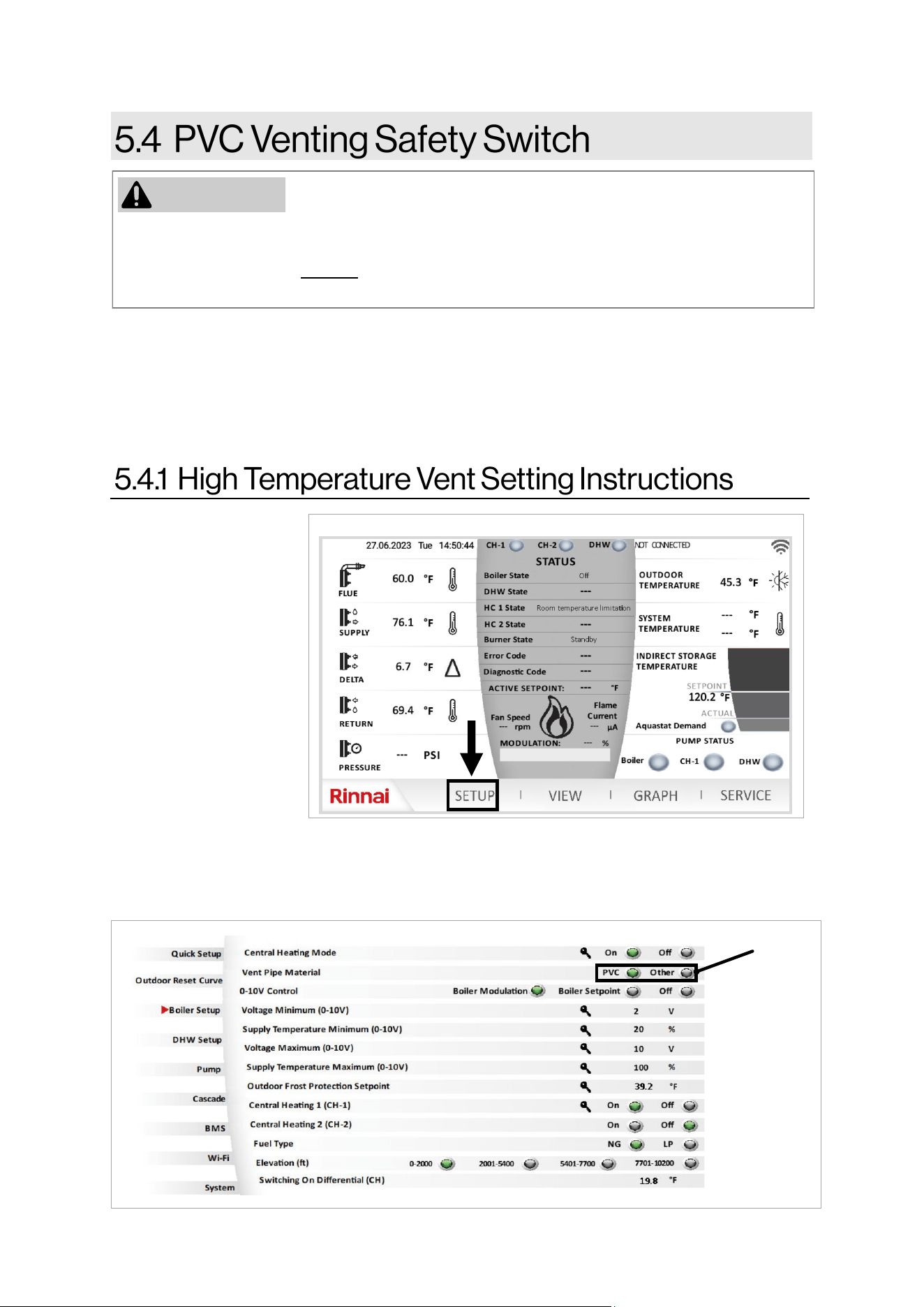
The instructions in this section explain how to adjust boiler settings to
allow for higher exhaust temperatures. These instructions apply only for
installations using CPVC, listed Polypropylene, or stainless steel venting. If these instructions are
not followed exactly, a fire or carbon monoxide leak may result causing property damage,
personal injury, or death. DO NOT adjust boiler settings to allow higher exhaust temperatures
when venting with PVC.
This product is equipped with safety devices to control the exhaust temperature which allows for a
variety of venting materials to be used in its final installation. The boiler is set up from the factory to
be installed with a PVC venting system and a built-in control to limit the exhaust temperature to be
below 149°F (65°C). In high temperature applications where the exhaust temperature can exceed
149°F (65°C), CPVC, listed Polypropylene (PP), or stainless steel venting must be used. The choice of
venting materials may have an impact on overall performance. Also, If the vent material is other than
PVC (CPVC, listed PP or stainless steel) follow the procedure below to adjust the internal settings.
1. Press “Setup” on
the home screen
(Figure 17).
2. The first screen of the setup function appears. Press “Boiler Setup” menu to access the screen
shown below.
3. Change the parameter “Vent Pipe Material” from “PVC” to “Other” to allow for higher vent
temperature (Figure 18).
Select
“Other”
Figure 17
WARNING
Figure 18
Rinnai Commercial Boiler Installation and Operation Manual 29
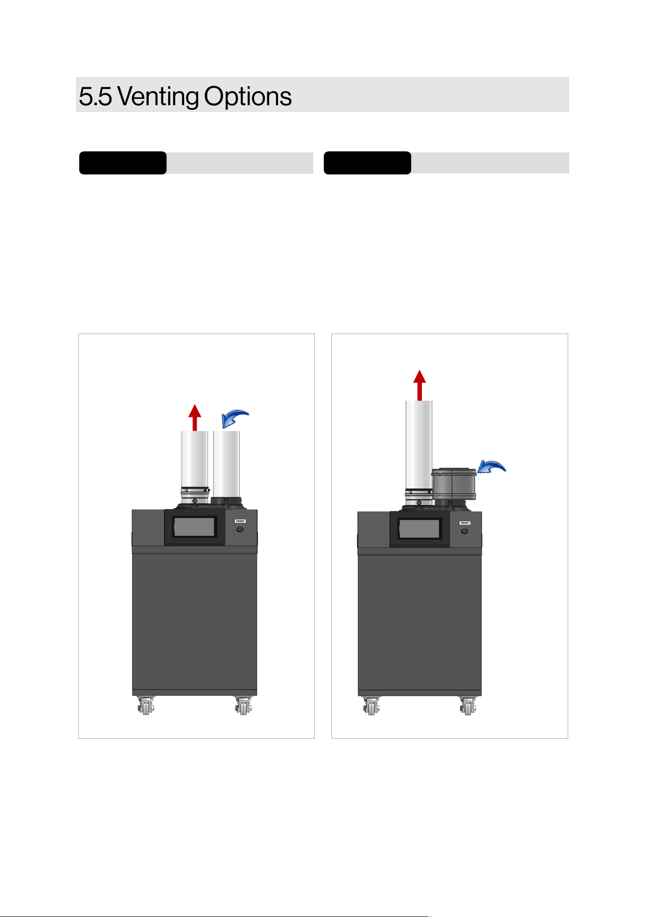
Two venng opons are available: Direct Vent and Non-Direct Vent (Room Air).
If installing a direct vent opon, combuson
air must be drawn from the outside directly
into the boiler intake and exhaust must
terminate outdoors. The vent terminaon can
be twin pipe (2 separate penetraons, or
concentric with a single penetraon)
See the Direct Vent secon for complete details.
Direct Vent
Opon 1 Opon 2
Non-Direct Vent (Room Air)
See the Non-Direct Vent secon for complete
details.
If installing a non-direct vent (room air), indoor
air is used for combuson while exhaust vents
to the outside.
Exhaust
Exhaust
Figure 19 Figure 20
Combuson
air (oponal
intake lter)
Combuson
air
30 Rinnai Commercial Boiler Installation and Operation Manual
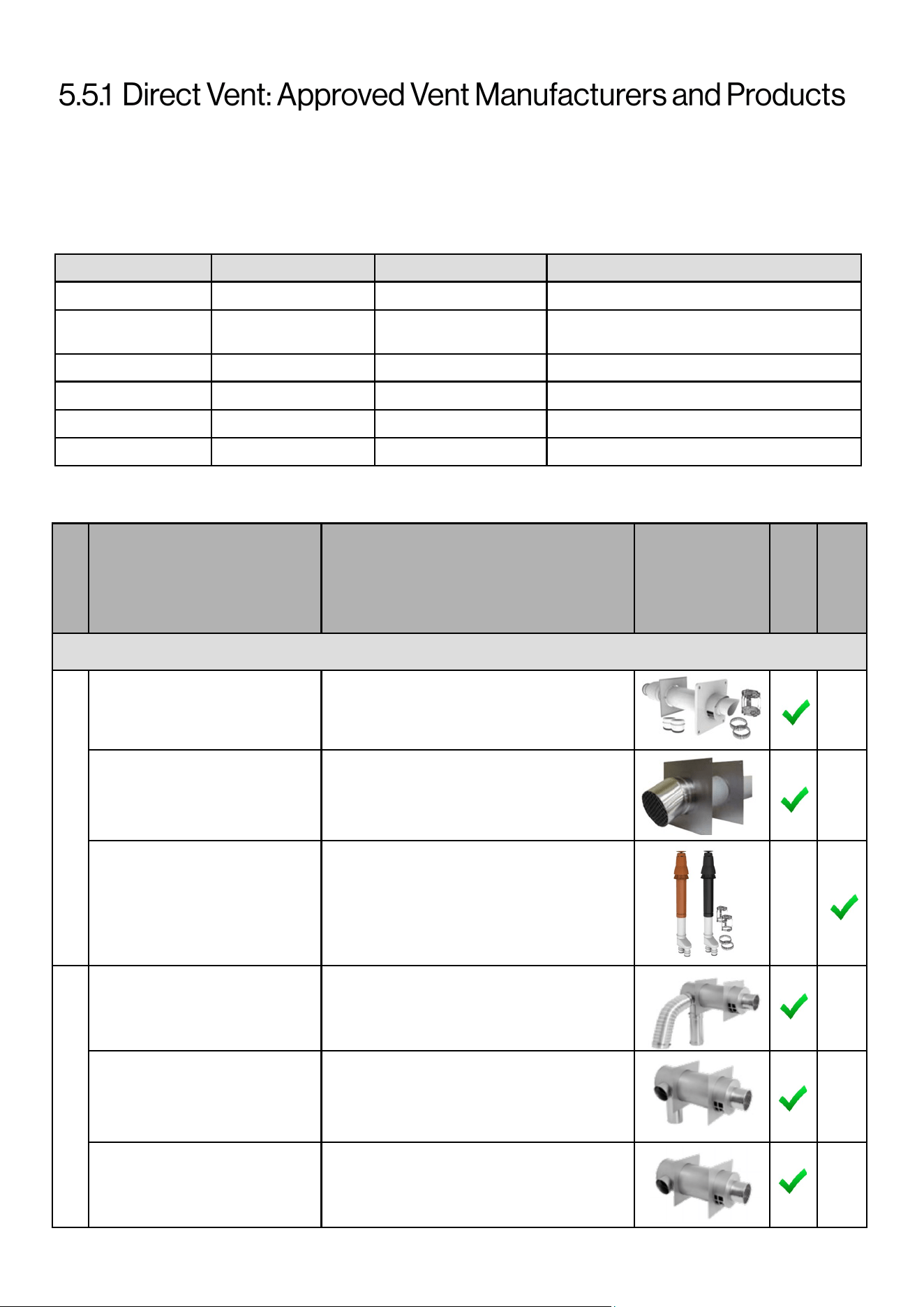
Following is a list of vent components and terminaons for Direct Vent installaons (concentric and twin pipe).
Install the correct venng for your model according to the venng manufacturer’s instrucons and the guidelines
below. The informaon below is correct at me of publicaon and is subject to change without noce. Contact the
vent manufacturer for quesons related to the vent system, products, part numbers and instrucons.
Manufacturer Phone Web Site Vent Material
Centrotherm 877-434-3432 www.centrotherm.us.com Polypropylene
IPEX
U.S.: 800-463-9572
Canada: 866-473-9462
www.ipexamerica.com, www.ipexinc.com PVC/CPVC
DuraVent 800-835-4429 www.duravent.com Polypropylene, Metal
Royal 800-232-5690 www.royalbuildingproducts.com PVC
ECCO Manufacturing 877-955-4805 www.eccomfg.com Polypropylene
DiversiTech 800-995-2222 www.diversitech.com PVC/CPVC
VENT TERMINATIONS (RCB50AN MODEL)
Table 12: Approved Vent Manufacturers
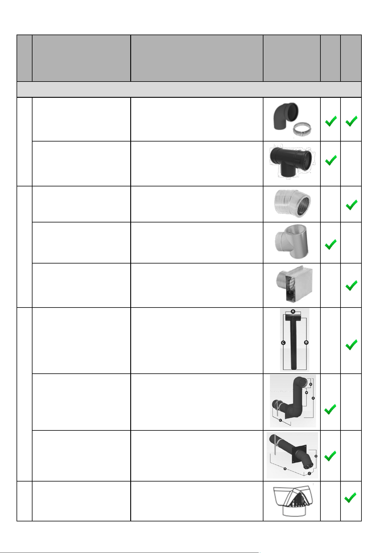
CONCENTRIC VENT TERMINATIONS (4 Inch)
4PPS-HKC
4”X6” PolyPro Horizontal Terminaon Kit
w/LB2
4PPS-HSTSL
4”x6” Horizontral Terminaon for
Commercial Systems
4PPS-VKC
4PPS-VK-TCC
4”x6” Vercal Terminaon Kit w/Black Cap
& LB2
4”x6” PolyPro Vercal Terminaon Kit w/
Terracoa Cap w/ LB2
FSEDVWMT04U 4” Universal Concentric Kit
FDVWMT04RH
FSEDVWMT04LH
Wall Mount Concentric Kit
Wall Mount Concentric Kit
FDVWT04 Remote Concentric Kit
Duravent
-PolyPro
Duravent
-FasNSeal
Diagram
Horizontal
Vercal
Product
Descripon
Manufacturer
Part Number/
Order Number
Manufacturer
Table 13
Rinnai Commercial Boiler Installation and Operation Manual 31
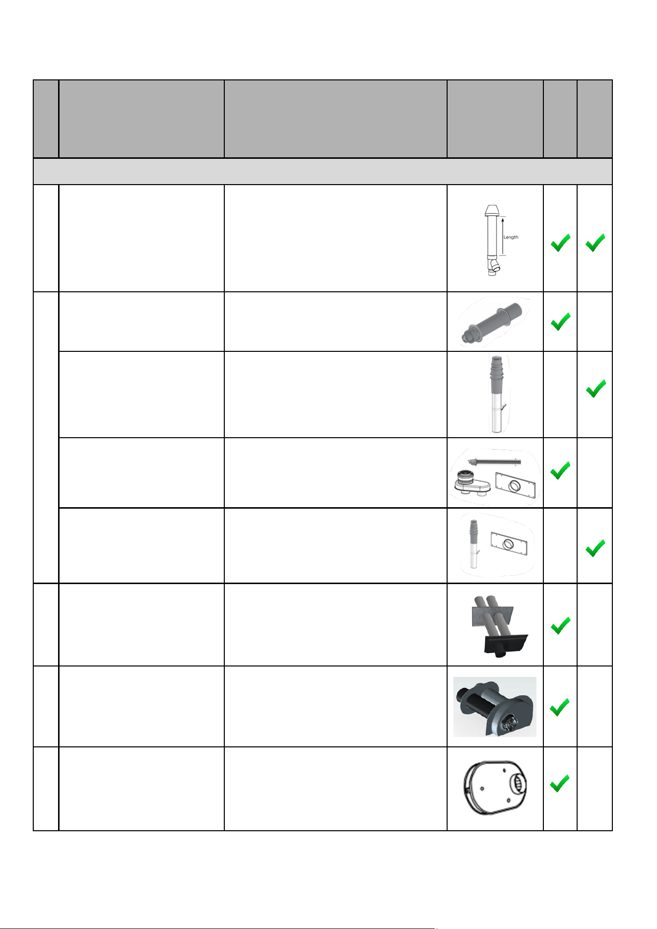
CONCENTRIC VENT TERMINATIONS (4 Inch) - CONT.
196021
197021
397021
System 636 Concentric Terminaon Kit -
PVC (white)
System 636 Concentric Terminaon Kit -
CPVC (grey)
System 1738 Concentric Terminaon Kit -
PVC (black)
190488
Horizontal Concentric Wall Terminaon-
Polypropylene
190295
Vercal Concentric Roof Terminaon-
Polypropylene
190483
4”x6” Horizontal Concentric Wall
Terminaon–Polypropylene
190484
4”x6” Vercal Concentric Roof Terminaon
-Polypropylene
4PPS-HTPC 4” Twin Pipe Terminaon-Polypropylene
ISLPT0404 4” Low Prole Wall Terminaon
196986
397986
System 636 FGV Low Prole Terminaon
Kit – PVC (Beige)
System 1738 FGV Low Prole Terminaon
Kit – PVC (Black)
IPEX
ECCO
Diagram
Horizontal
Vercal
Product
Descripon
Manufacturer
Part Number/
Order Number
Manufacturer
Duravent
Centrotherm
IPEX
Table 13 connue
32 Rinnai Commercial Boiler Installation and Operation Manual
TWIN PIPE TERMINATIONS (4 Inch) - CONT.
4PPS-E90BC 4” Black UV Resistant 90 elbow
4PPS-TBC 4” Black Terminaon Tee
FSBS4 4” Bird Screen 23°
FSTT4 4” Terminaon Tee
FSTB4 4” Terminaon Box
ISTT0420 4” Terminaon Tee
ISSNKL041 4” Snork
ISHT0445 4” Snout
286715 SGV Rain Cap
Duravent
-FasNSeal
Diagram
Horizontal
Vercal
Product
Descripon
Manufacturer
Part Number/
Order Number
Manufacturer
Centrotherm
Duravent
-PolyPro
IPEX
Table 13 connued
Rinnai Commercial Boiler Installation and Operation Manual 33
VENT TERMINATIONS (RCB750AN & RCB1000AN MODELS)
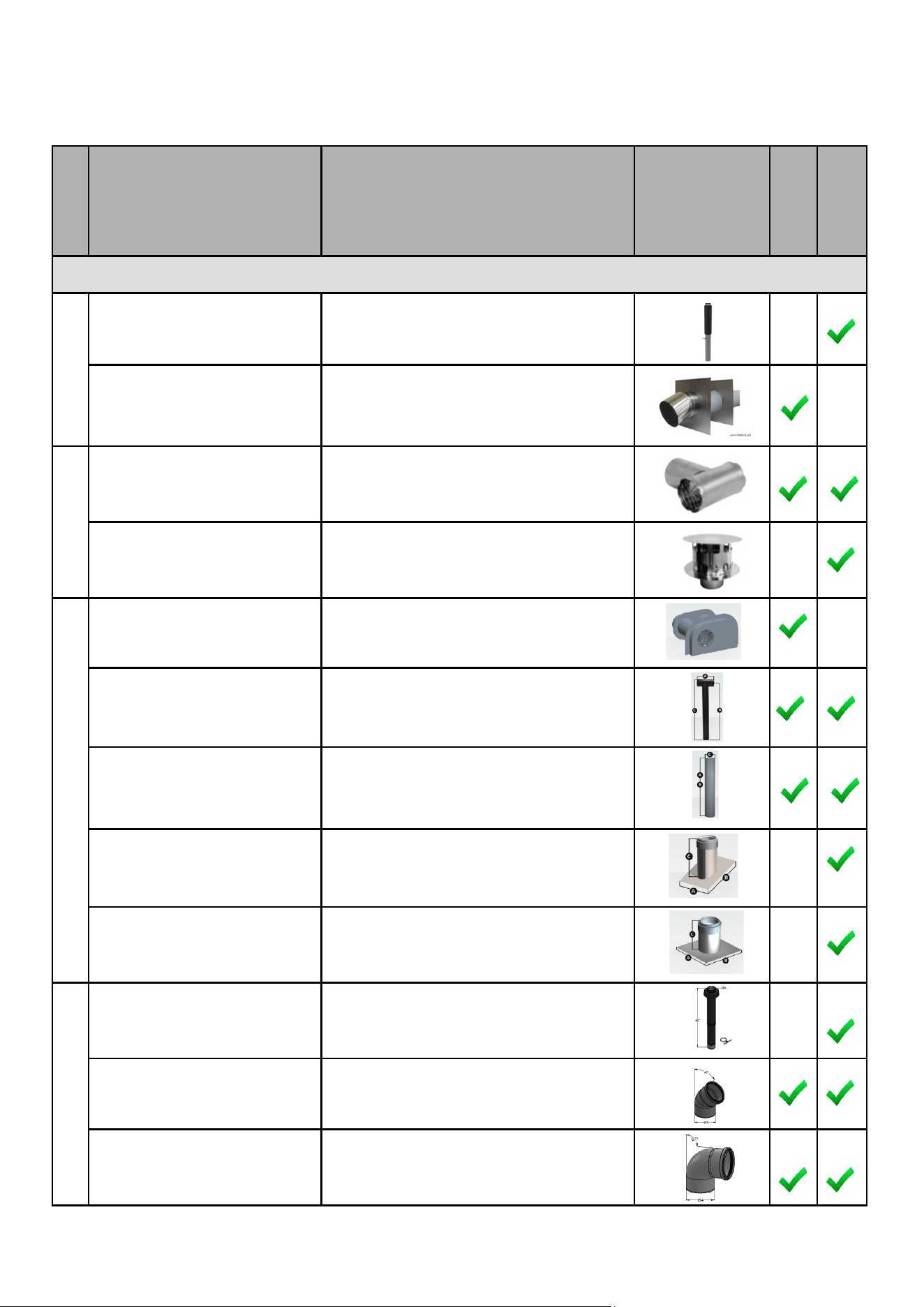
CONCENTRIC VENT TERMINATIONS (6 inch) - CONT.
6PPS-VTMC Vercal Terminaon
6PPS-HSTL Horizontal Terminaon
FSTT6 6 Inch Terminaon Tee
FSRC6 Rain Cap
ISLPT0606 Low Prole Wall Terminaon
ISTT0620 Terminaon Tee
ISEP06 End Pipe PP Gray
IAPRF06 Pitched Roof Flashing
IAFRF06 Flat Roof Flashing
190628 Single Wall Vercal Terminaon
190613 87 degree elbow - UV resistant
190611 45 degree elbow - UV resistant
Duravent
-PolyPro
Duravent
-FasNSeal
Diagram
Horizontal
Vercal
Product
Descripon
Manufacturer
Part Number/
Order Number
Manufacturer
Centrotherm
ECCO
Table 14
34 Rinnai Commercial Boiler Installation and Operation Manual
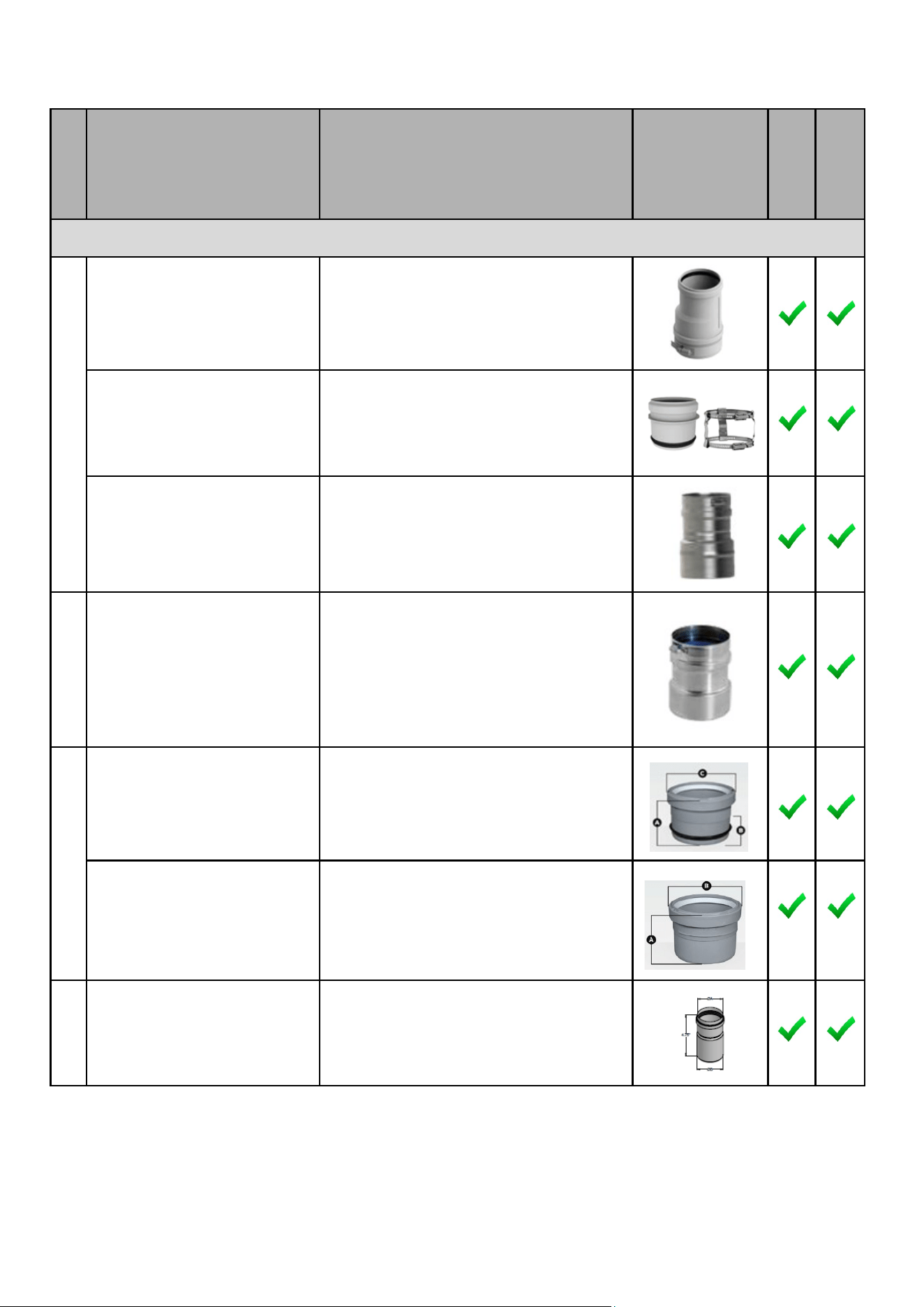
APPLIANCE ADAPTER (4 Inch and 6 Inch)
4PPS-AD-M Appliance Adapter for PVC Pipe - 4 Inch
4PPS-ADL
Appliance Adapter for PVC Coupler - 4 Inch
4PPS-04PVCM-4PPF
6PPS-06PVCM-6PPF
Male PVC Appliance Adapter - 4 Inch
Male PVC Appliance Adapter - 6 Inch
FSA-04M-4PPF
FSA-04M-4PPF
PVC to FasNSeal Appliance Adapter - 4 Inch
PVC to FasNSeal Appliance Adapter - 6 Inch
ISAGL0404
ISAGL0606
Appliance Adapter - PVC to PP - 4 Inch
Appliance Adapter - PVC to PP - 6 Inch
ISAAL0404
ISAAL0606
Appliance Adapter – PVC to PP - 4 Inch
Appliance Adapter – PVC to PP - 6 Inch
4PPSSAD Appliance Adapter-SS - 4 Inch
Duravent
-FasNSeal
Diagram
Horizontal
Vercal
Product
Descripon
Manufacturer
Part Number/
Order Number
Manufacturer
Centrotherm
Duravent
-PolyPro
ECCO
Table 14 connue
Rinnai Commercial Boiler Installation and Operation Manual 35
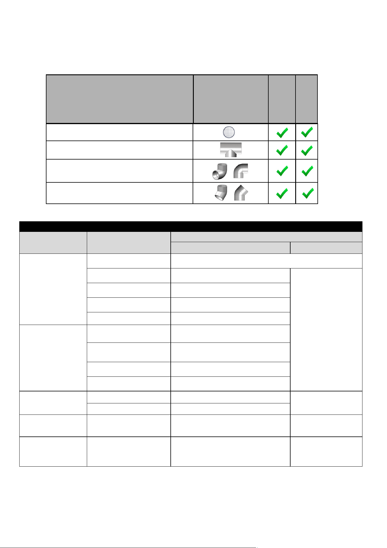
VARIOUS 4 in. and 6 in. SCHEDULE 40 PVC/CPVC TERMINATIONS
Approved Materials for Exhaust and Intake Pipe
Item Material
Standard for Installaon in North America
United States Canada
Pipe
(Intake or Exhaust)
SS AL29-4C Cered for direct vent category IV appliance
PVC Schedule 40/80 UL-1738 or ANSI/ASTM D1785
UL-1738 or ULC -S636
Intake pipe may be of
the materials listed in
this table.
PVC-DWV Schedule 40/80 UL-1738 or ANSI/ASTM D2665
CPVC Schedule 40/80 UL-1738 or ANSI/ASTM F441
Polypropylene UL-1738 or ULC-S636
Fing
(Intake or Exhaust)
PVC Schedule 40 UL-1738, ANSI/ASTM D2465 or D2666
PVC Schedule 80
UL-1738, ANSI/ASTM D2465 or
D26667
CPVC Schedule 40 UL-1738 or ANSI/ASTM F438
CPVC Schedule 80 UL-1738 or ANSI/ASTM F438
Pipe Cement and
Primer
PVC ANSI/ASTM D2564
ULC -S636
CPVC ANSI/ASTM F493
Pipe and Fings for
Intake Only
ABS ANSI/ASTM D2661 ANSI/ASTM D2661
Pipe Cement and
Primer for Intake
Only
ABS ANSI/ASTM D2235 ANSI/ASTM D2235
NOTICE: DO NOT USE CELLULER (FOAM) CORE PIPE FOR EXHAUST VENTING.
Refer to the PVC/CPVC manufacturer for appropriate ngs, solvents or joining methods.
Air Filter Screen
Tee
90° Elbow
45° Elbow
Product
Descripon
Diagram
Horizontal
Vercal
Table 16: Approved Materials for Exhaust and Intake Pipe
Table 15
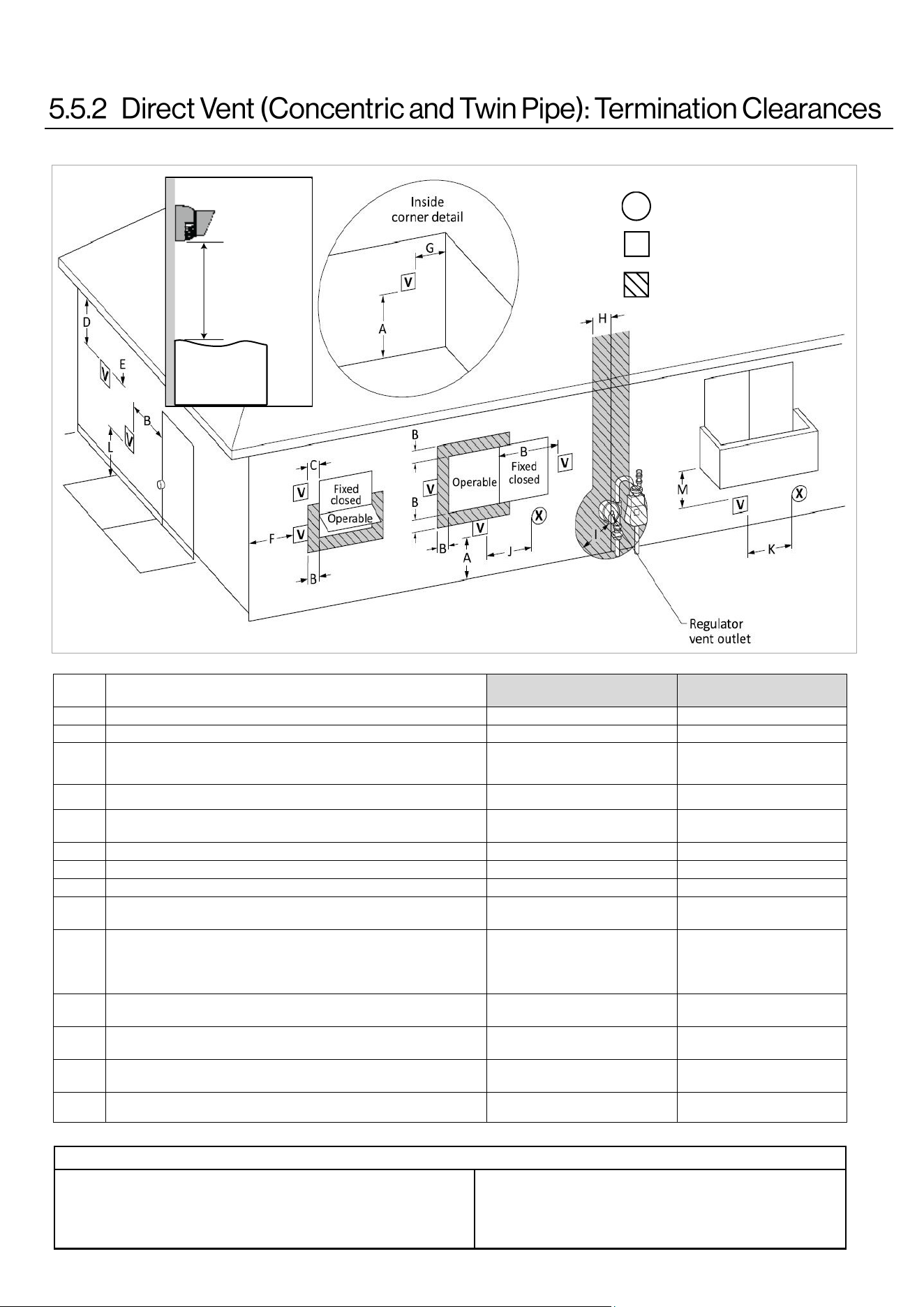
36 Rinnai Commercial Boiler Installation and Operation Manual
Canadian Installaons
(CSA B149.1)
U.S. Installaons
(ANSI Z223.1 /NFPA 54)
Ref Descripon Direct Vent (Indoor Unit) Direct Vent (Indoor Unit)
A Clearance above grade, veranda, porch, deck, or balcony 12 in. (30 cm) 12 in. (30 cm)
B Clearance to window or door that may be opened 36 in. (91 cm)
4 (1.2 m) below or to side of
opening;
1 (30 cm) above opening
C Clearance to permanently closed window * *
D
Vercal clearance to venlated sot, located above the terminal within a
horizontal distance of 2 (61 cm) from the center line of the terminal
* *
E Clearance to unvenlated sot * *
F Clearance to outside corner * *
G Clearance to inside corner * *
H
Clearance to each side of center line extended above meter/regulator
assembly
* *
I Clearance to service regulator vent outlet
Above a regulator within 3
(91 cm) horizontally of the vercal
center line of the regulator vent
outlet to a maximum vercal
distance of 15 (4 m)
*
J
Clearance to non-mechanical air supply inlet to building or the
combuson air inlet to any other appliance
36 in. (91 cm) 12 in. (30 cm)
K Clearance to a mechanical air supply inlet 6 (1.83 m)
3 (91 cm) above if within
10 (3 m) horizontally
L
Clearance above paved sidewalk or paved driveway located on public
property
7 (2.13 m) [1] *
M Clearance under veranda, porch, deck, or balcony 12 in. (30 cm) [2] *
AIR SUPPLY INLET
VENT TERMINAL
AREA WHERE TERMINAL
IS NOT PERMITTTED
X
V
SNOW
TERMINATION
Clearance in
Ref. A also
applies to
anticipated
snow line
Clearance to opposite wall is 24 in. (60 cm).
[1] A vent shall not terminate directly above a sidewalk or paved driveway that
is located between two single family dwellings and serves both dwellings.
[2] Permied only if veranda, porch, deck, or balcony is fully open on a mini-
mum of two sides beneath the oor.
Clearances are in accordance with local installaon codes and the
requirements of the gas supplier.
The informaon below applies to Concentric and Twin Pipe.
Figure 21
Table 17: Direct Vent Terminaon Clearances - ANSI Z223.1 / NFPA54 for US and CAN/CSA B149.1 for Canada.
Table 18
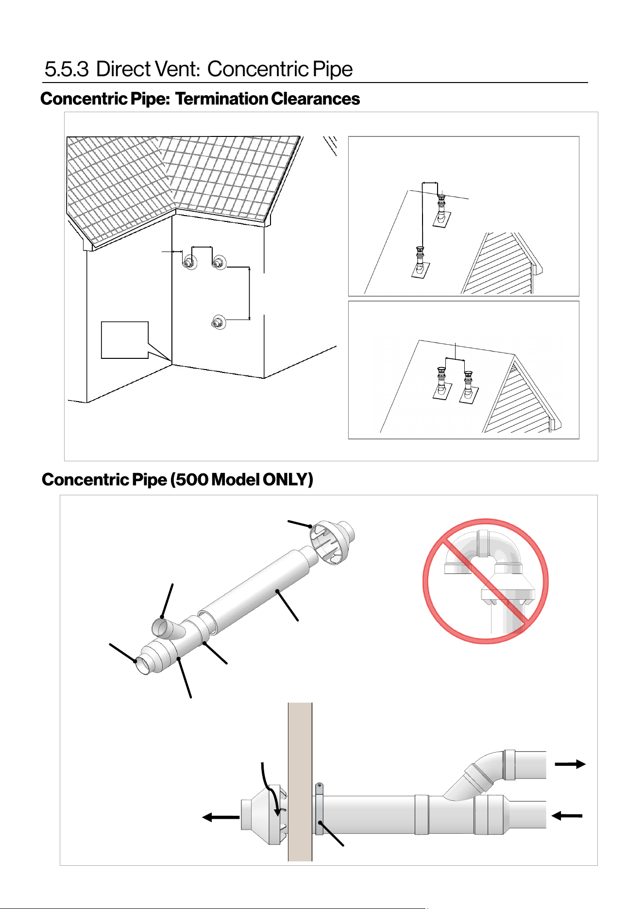
Rinnai Commercial Boiler Installation and Operation Manual 37
12 in. (0.30 m)
Between terminals at same level
60 in. (1.52 m)
Between terminals at different levels
Note: 24 in. (0.61 m)
to wall or parapet
All terminations (horizontal and/or vertical) must
terminate 12 in. (0.30 m) above grade or anticipated
snow level.
Inside
Corner
12 in.
(0.30 m)
60 in. (1.52 m)
vertically between
terminals
“Y” Concentric
Fitting
6” (152 mm) Dia.
4” (102 mm) Dia.
Through all
4” (102 mm)
Dia.
Through all
6” (152 mm) Dia.
Rain Cap
Strap
Vent
Vent
Combustion
Air
Combustion
Air
Do Not Install U-Bend to
Rain Cap
Figure 22
Figure 23
12 in.
(0.30 m)
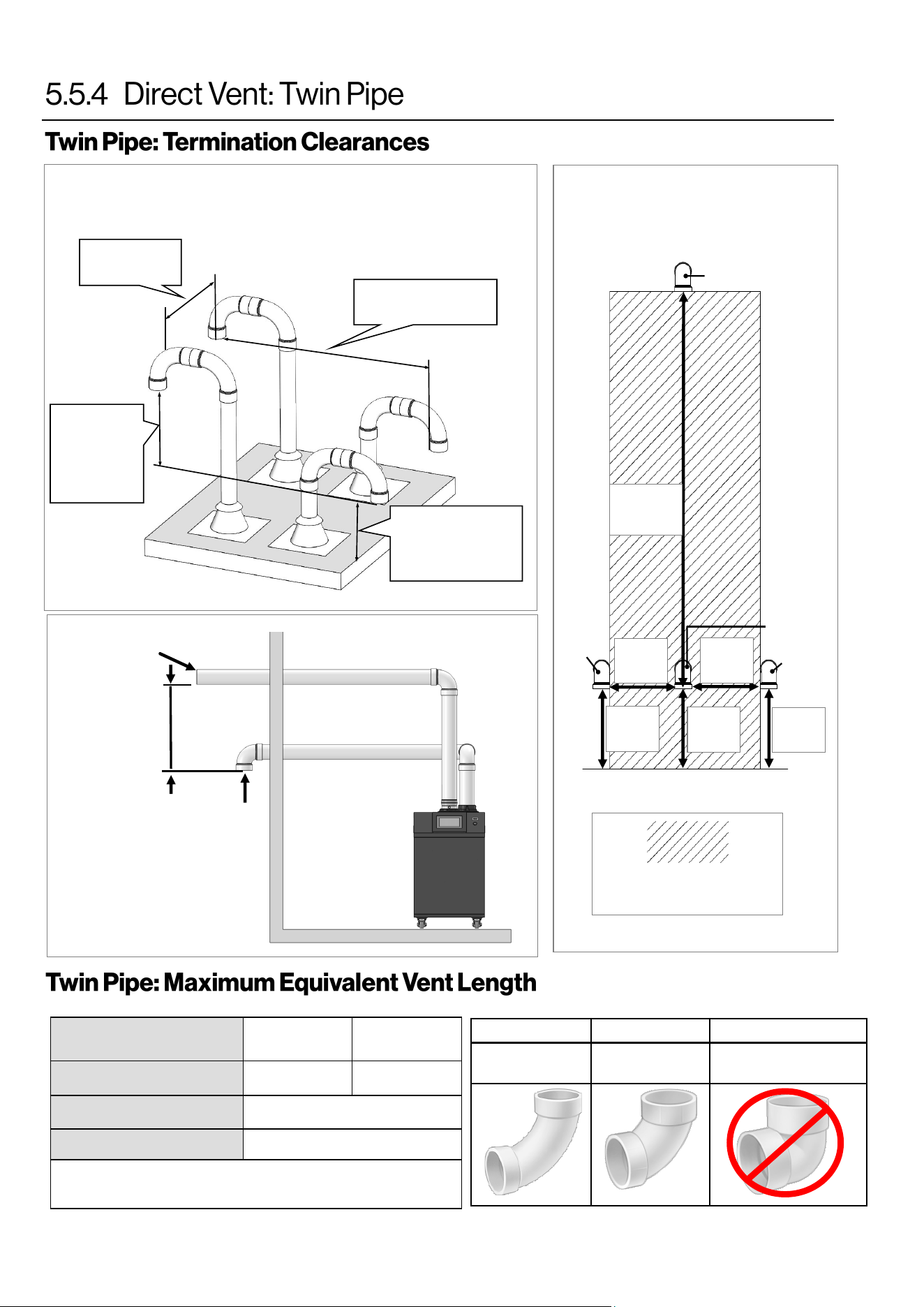
38 Rinnai Commercial Boiler Installation and Operation Manual
Twin Pipe Vercal Terminaon
of Mulple Boilers
12 in. (0.30 m)
minimum
12 in. (0.30
m) minimum
above
combuson
air opening
Roof
12 in. (0.30 m)
above grade or
ancipated snow
level
12 in. (0.30 m)
minimum
Combuson
Air
Exhaust
ACCEPTABLE ACCEPTABLE NOT ACCEPTABLE
90° Elbows,
Long Sweep
90° Elbows,
Short Sweep
90° Elbows,
Close Turn
Indicates area in which
intake cannot be located.
Intake
Ground/Grade/Snow Level
60 in.
(152 cm)
Min.
12 in.
(30 cm)
Min.
Intake
Exhaust
Intake
12 in.
(30 cm)
Min.
12 in.
(30 cm)
Min.
12 in.
(30 cm)
Min.
12 in.
(30 cm)
Min.
Figure 24
Figure 26
Horizontal Vent and
Combuson Air Piping
Sidewall Clearances
Combuson
Air Intake
Exhaust
12 in.
(0.30 m)
Figure 25
MODEL
RCB500AN
RCB750AN and
RCB1000AN
Vent Sizes 4 in. PVC/CPVC 6 in. PVC/CPVC
Min-Max Exhaust Vent Run
10 feet (3 meters) - 140 (43 m)
Min-Max Intake Vent Run
0 feet (0 meters) - 140 (43 m)
• 45° elbow is equivalent to 3 (1 m)
• 90° elbow is equivalent to 6 (2 m)
Vent length includes the addional venng, ngs and terminaons.
Table 19: Twin Pipe Maximum Equivalent Vent Lengths
Table 20
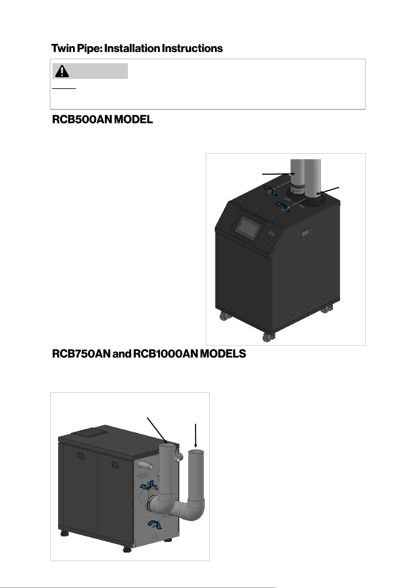
Rinnai Commercial Boiler Installation and Operation Manual 39
DO NOT apply PVC glues, solvents, or cleaners to the boiler’s combuson air or exhaust gasket connecons.
Failure to correctly assemble the components according to these instrucons may result in property damage,
personal injury, or death.
1.
Exhaust Pipe: Align and slide down PVC/CPVC
pipe on the exhaust vent connecon.
NOTE: Ensure that the pipe passes through
the rubber gasket on the metal vent adapter
and also hits a stop on the vent connecon.
4.
2.
Secure the pipe to the intake air adapter
using 3 screws (supplied with appliance).
To secure the exhaust air vent pipe, ghten
the clamp aached on exhaust air vent using
a screwdriver.
WARNING
Combuson
Air Pipe
Exhaust Vent
Pipe
3.
Air Intake: Align and slide down PVC/CPVC
pipe on the air intake connecon.
1.
Exhaust Pipe: Align and insert the PVC/CPVC
pipe on the exhaust vent connecon.
NOTE: Ensure that the pipe passes through the
rubber gasket on the metal vent adapter and
also hits a stop on the vent connecon.
4.
2.
Secure the pipe to the intake air adapter
using 3 screws (supplied with appliance).
To secure the exhaust air vent pipe, ghten
the clamp aached on exhaust air vent using
a screwdriver.
3.
Air Intake: Align and insert the PVC/CPVC
pipe on the air intake connecon unl it hits
a stop.
Combuson
Air Pipe
Exhaust Vent
Pipe
The intake and exhaust adapters on top of the appliance are designed to t 4 Inch PVC/CPVC pipe. When
using other vent materials such as PP and Stainless Steel pipes ensure to use an appliance adapter from the
pipe manufacturer to properly connect to the boiler adapters.
The intake and exhaust adapters on back of the appliance are designed to t 6 Inch PVC/CPVC pipe. When
using other vent materials such as PP and Stainless Steel pipes ensure to use an appliance adapter from the
pipe manufacturer to properly connect to the boiler adapters.
Figure 27
Figure 28
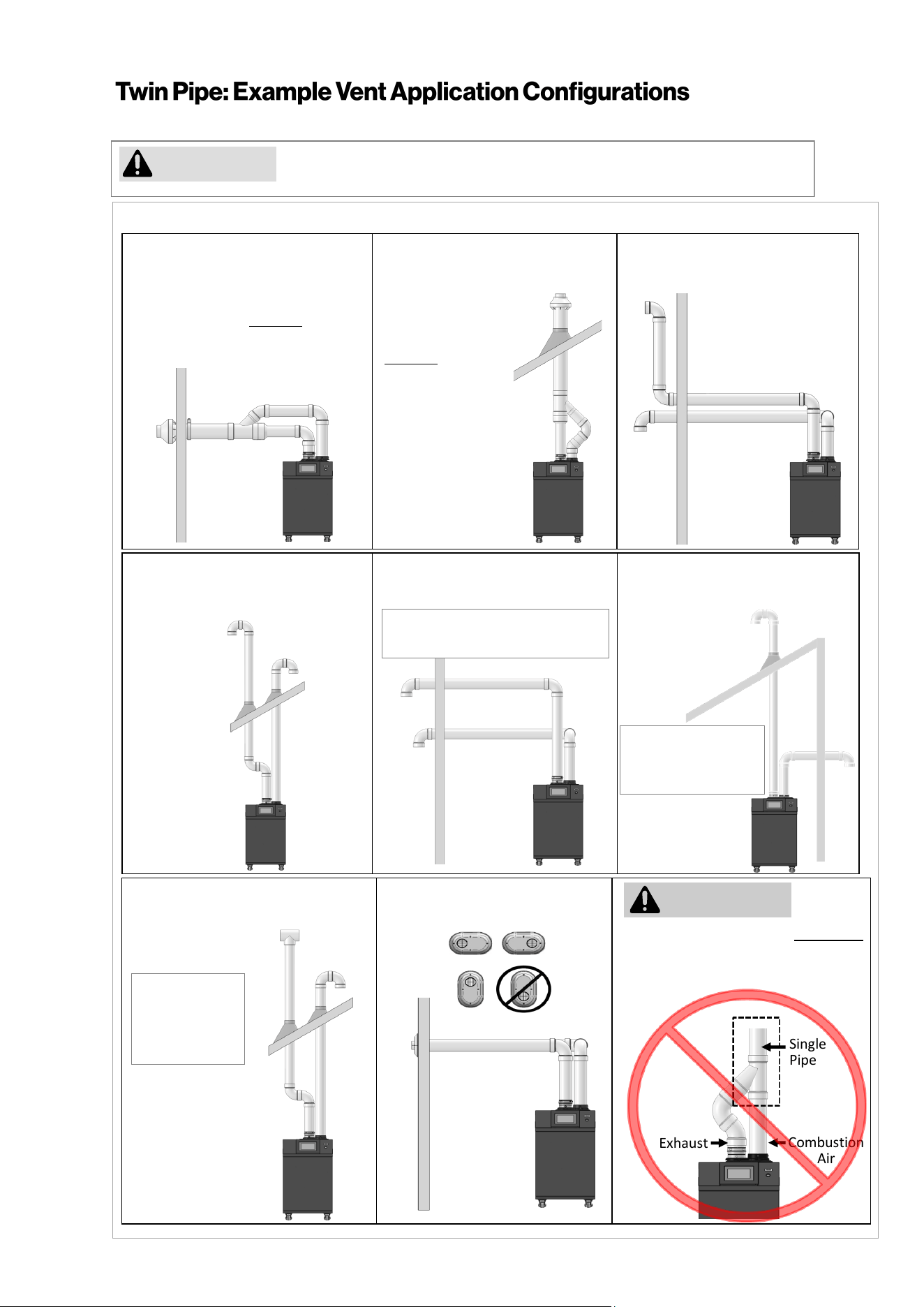
40 Rinnai Commercial Boiler Installation and Operation Manual
Rinnai cautions against installing the boiler in applications with venting in different
pressure planes. It is possible to have poor performance with this installation.
Slope horizontal exhaust 1/4 in. per foot towards the boiler. DO NOT slope combustion air pipe towards the boiler.
CAUTION
Combustion
Air
Exhaust
Single
Pipe
Tee not permissible for intake
termination
Exhaust and combustion air MUST NOT
be brought together into a single PVC
pipe using a pipe fitting.
Schedule 40 PVC/CPVC Standard
Upside Down
"U" Vertical Termination
Schedule 40 PVC/CPVC
Elbow or Tee Side Wall Termination
Schedule 40 PVC/CPVC
Tee Vertical Termination
PVC Low Profile Termination
Tee not
permissible for
intake
termination
Figure 29
WARNING
This conguraon requires the use
of a Concentric Vent Terminaon.
PVC/CPVC
IPEX / Royal Concentric
Side Wall Terminaon
PVC/CPVC
IPEX /Royal Concentric
Vercal
Terminaon
Schedule 40 PVC/CPVC Snorkel
Terminaon
This conguraon
requires the use of
a Concentric Vent
Terminaon.
Schedule 40 PVC/CPVC
Side Wall Intake Vertical Exhaust
Tee not permissible
for intake
termination
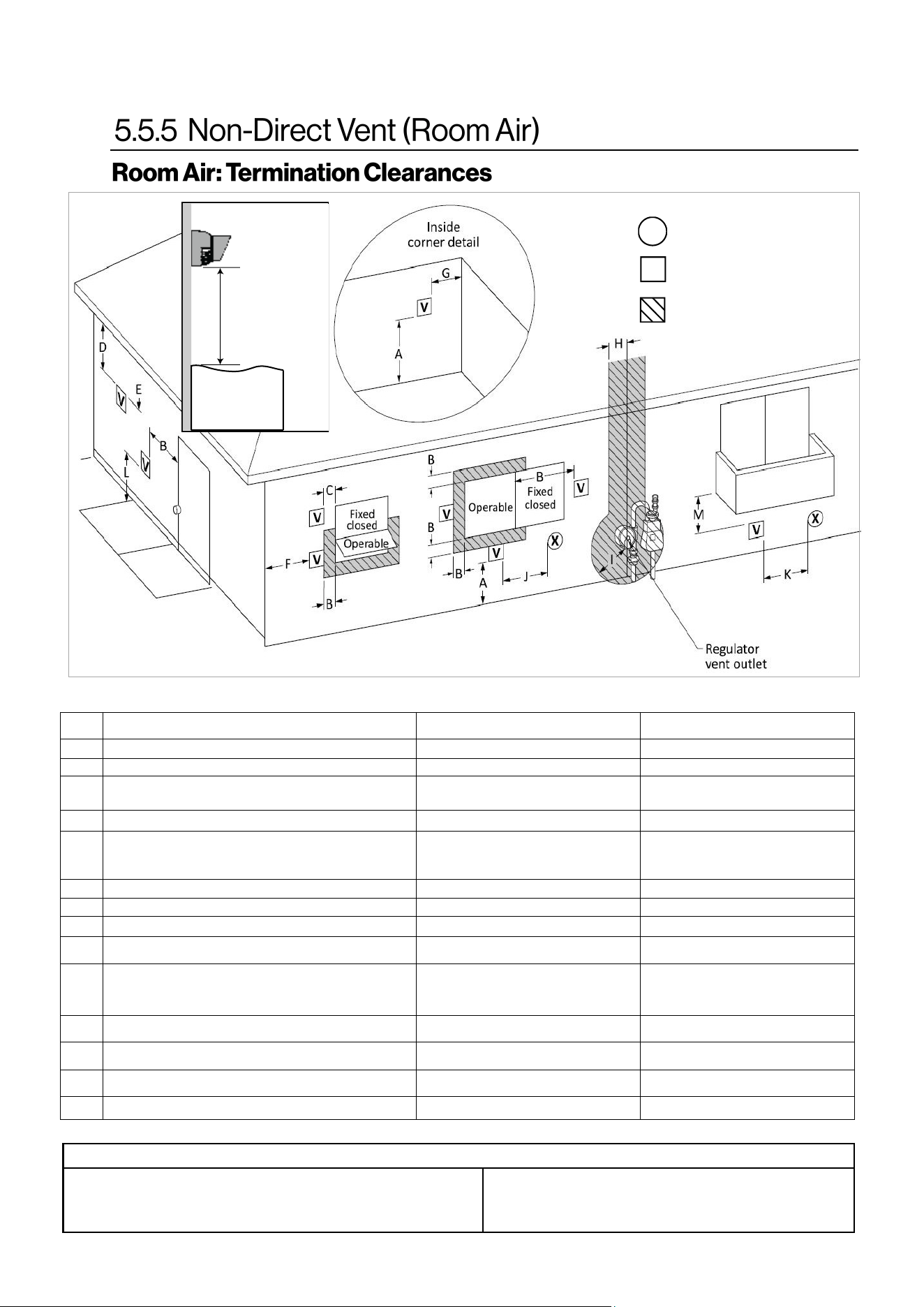
Rinnai Commercial Boiler Installation and Operation Manual 41
Canadian Installaons
(CSA B149.1)
U.S. Installaons
(ANSI Z223.1 /NFPA 54)
Ref Descripon Other than Direct Vent (Room Air) Other than Direct Vent (Room Air)
A Clearance above grade, veranda, porch, deck, or balcony 12 in. (30 cm) 12 in. (30 cm)
B Clearance to window or door that may be opened 36 in. (91 cm)
4 (1.2 m) below or to side of opening;
1 (30 cm) above opening
C Clearance to permanently closed window * *
D
Vercal clearance to venlated sot, located above the
terminal within a horizontal distance of 2 (61 cm) from
the center line of the terminal
* *
E Clearance to unvenlated sot * *
F Clearance to outside corner * *
G Clearance to inside corner * *
H
Clearance to each side of center line extended above
meter/regulator assembly
* *
I Clearance to service regulator vent outlet
Above a regulator within 3 (91 cm)
horizontally of the vercal center line of
the regulator vent outlet to a maximum
vercal distance of 15 (4 m)
*
J
Clearance to non-mechanical air supply inlet to building or
the combuson air inlet to any other appliance
36 in. (91 cm)
4 (1.2 m) below or to side of opening;
1 (30 cm) above opening
K Clearance to a mechanical air supply inlet 6 (1.83 m)
3 (91 cm) above if within 10
(3 m) horizontally
L
Clearance above paved sidewalk or paved driveway located
on public property
7 (2.13 m) [1] 7 (2.13 m)
M Clearance under veranda, porch, deck, or balcony 12 in. (30 cm) [2] *
AIR SUPPLY INLET
VENT TERMINAL
AREA WHERE TERMINAL IS
NOT PERMITTTED
X
V
SNOW
TERMINATION
Clearance in
Ref. A also
applies to
anticipated
snow line
Clearance to opposite wall is 24 in. (60 cm).
[1] A vent shall not terminate directly above a sidewalk or paved driveway that is
located between two single family dwellings and serves both dwellings.
[2] Permied only if veranda, porch, deck, or balcony is fully open on a minimum
of two sides beneath the oor.
Clearances are in accordance with local installaon codes and the
requirements of the gas supplier.
Figure 30
Table 21: Room Air Terminaon Clearances
Table 22
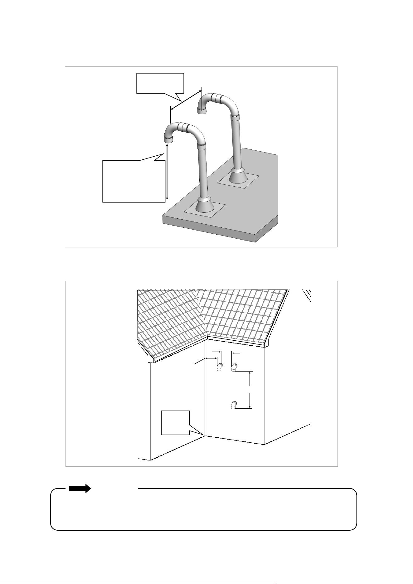
42 Rinnai Commercial Boiler Installation and Operation Manual
Room Air Vertical Termination of Multiple Boilers
Exhaust Termination Clearances for Internal (Indoor) Room Air Applications
Exhaust
Roof
12 in. (0.30 m)
minimum
12 in. (0.30 m)
above grade or
anticipated snow
level
60 in. (1.52 m)
12 in.
12 in.
(0.30 m)
Inside
Corner
Vertically
between
terminals
IMPORTANT
• Installation of Room Air must use listed Category IV venting.
• All terminations (horizontal and/or vertical) must terminate 12 in. above grade or anticipated
snow level.
Figure 31
Figure 32
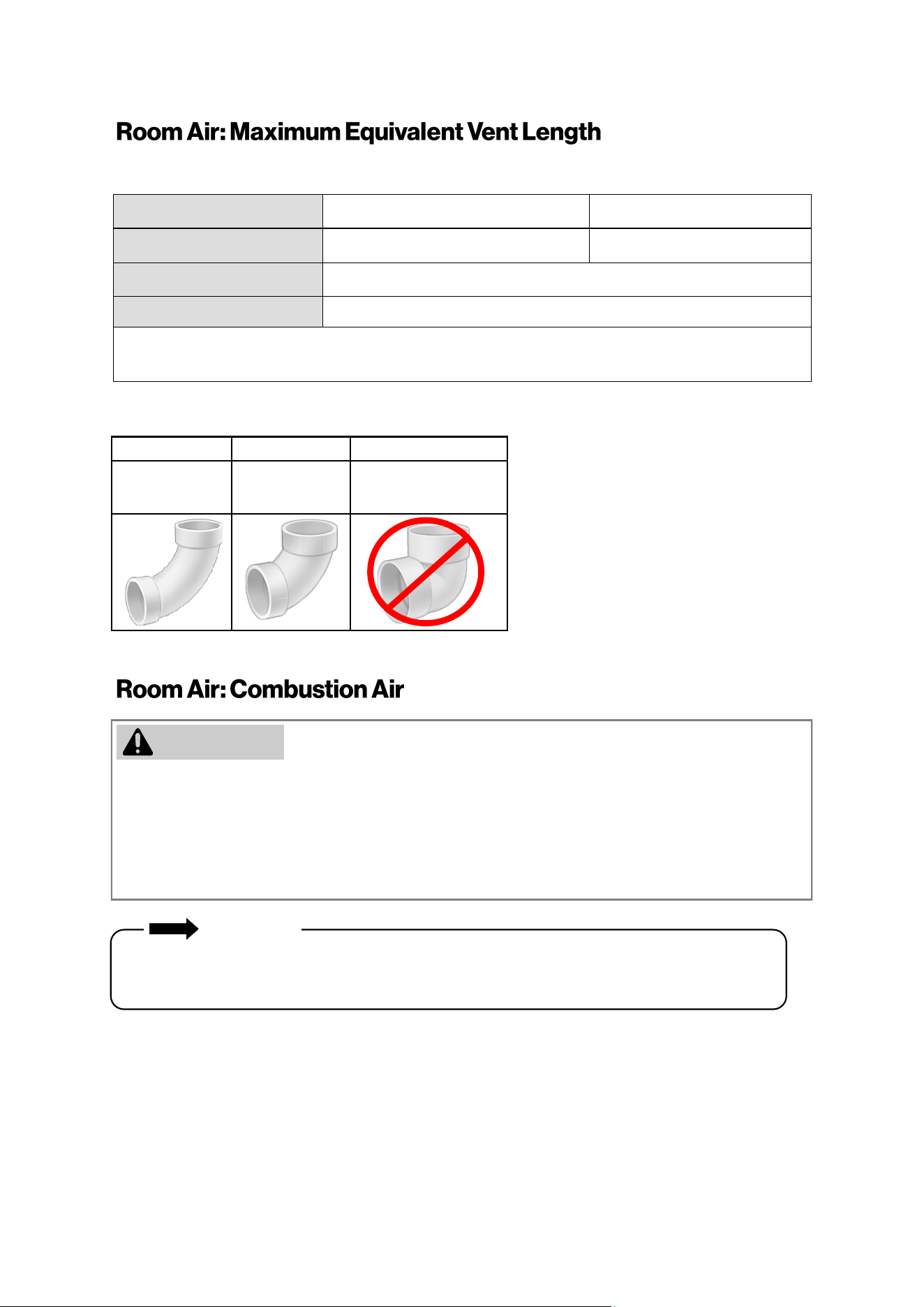
Rinnai Commercial Boiler Installation and Operation Manual 43
MODEL RCB500AN RCB750AN and RCB1000AN
Vent Sizes 4 in. PVC/CPVC 6 in. PVC/CPVC
Min-Max Exhaust Vent Run
10 feet (3 meters) - 140 feet (43 meters)
Min-Max Intake Vent Run
0 feet (0 meters) - 140 feet (43 meters)
• 45° elbow is equivalent to 3 (1 m)
• 90° elbow is equivalent to 6 (2 m)
• This boiler requires adequate combuson air for venlaon and diluon of ue gases. Failure to provide
adequate combuson air can result in unit failure, re, explosion, serious bodily injury or death. Use the
following methods to ensure adequate combuson air is available for correct and safe operaon of this
boiler.
• Direct Venng is recommended in unusually ght buildings or in installaon locaons subject to
signicant negave air pressure.
Combuson air must be free of corrosive chemicals. Do not provide combuson air from corrosive
environments. Appliance failure due to corrosive air is not covered by warranty.
IMPORTANT
ACCEPTABLE ACCEPTABLE NOT ACCEPTABLE
90° Elbows,
Long Sweep
90° Elbows,
Short Sweep
90° Elbows,
Close Turn
Vent length includes the addional venng, ngs and terminaons.
For applicaons containing corrosive indoor air, this appliance must be installed as direct vent. DO NOT use
room air in applicaons where combuson air contains acid forming chemicals such as sulfur, uorine and
chlorine. These chemicals have been found to cause rapid damage and decay and can become toxic when
used as combuson air in gas appliances. Such chemicals can be found in, but not limited to bleach,
ammonia, cat lier, aerosol sprays, cleaning solvents, varnish, paint and air fresheners. Do not store these
products or similar products in the vicinity of this boiler.
Table 23: Room Air Maximum Equivalent Vent Lengths
WARNING
Table 24

44 Rinnai Commercial Boiler Installation and Operation Manual
Unconned Space
An unconned space is dened in Naonal Fuel Gas Code, ANSI Z223.1/NFPA 54 as “a space whose volume is
not less than 50 cubic feet per 1000 Btu/hr (4.8 m3 per kW per hour) of the aggregate input rang of all
appliances installed in that space. Rooms communicang directly with the space in which the appliances are
installed, through openings not furnished with doors, are considered a part of the unconned space.” If the
“unconned space” containing the appliance(s) is in a building with ght construcon, addional outside air
may be required for proper operaon. Outside air openings should be sized the same as for a conned
space.
Conned Space
A conned space is dened in the Naonal Fuel Gas Code, ANSI Z223.1/NFPA 54 as "a space whose volume is
less than 50 cubic feet per 1000 Btu/hr (4.8 m3 per kW per hour) of the aggregate input rang of all
appliances installed in that space." Examples include a small room, closet, alcove, ulity room, etc. A
conned space must have two combuson air openings. Size the combuson air openings based on the Btu
input for all gas ulizaon equipment in the space and the method by which combuson air is supplied.
Using Indoor Air For Combuson
When using air from other room(s) in the building, the total volume of the room(s) must be of adequate
volume (greater than 50 cubic feet per 1000 Btu/hr). Combuson air openings between joining rooms must
have at least 1 square inch of free area for each 1000 Btu/hr, but not less than 100 square inches each.
Using Outdoor Air For Combuson
Outdoor air can be provided to a conned space through two permanent openings, one commencing within
12 in. (0.30 m) of the top and one commencing within 12 in. (0.30 m) of the boom, of the conned space.
The openings shall communicate to the outside by one of two ways.
When communicang directly with the outdoors through horizontal ducts, each opening shall have a
minimum free area of 1 in
2
/2000 Btu/hr (1100 mm
2
/kW) of total input rang of all appliances in the conned
space.
Note: If ducts are used, the cross seconal area of the duct must be greater than or equal to the required
free area of the openings to which they are connected.
Louvers and Grills
When sizing the permanent opening consideraon must be taken for the design of the louvers or grills to
maintain the required free area required for all gas ulizing equipment in the space. If the free area of the
louver or grill design is not available, assume wood louvers will have 25% free area and metal louvers or grills
will have 75% free area. Under no circumstance should the louver, grill or screen have openings smaller than
1/4 in.
Examples: Wood: 10 in. x 12 in. x 0.25 = 30 in.
2
Metal: 10 in. x 12 in. x 0.75 = 90 in.
2
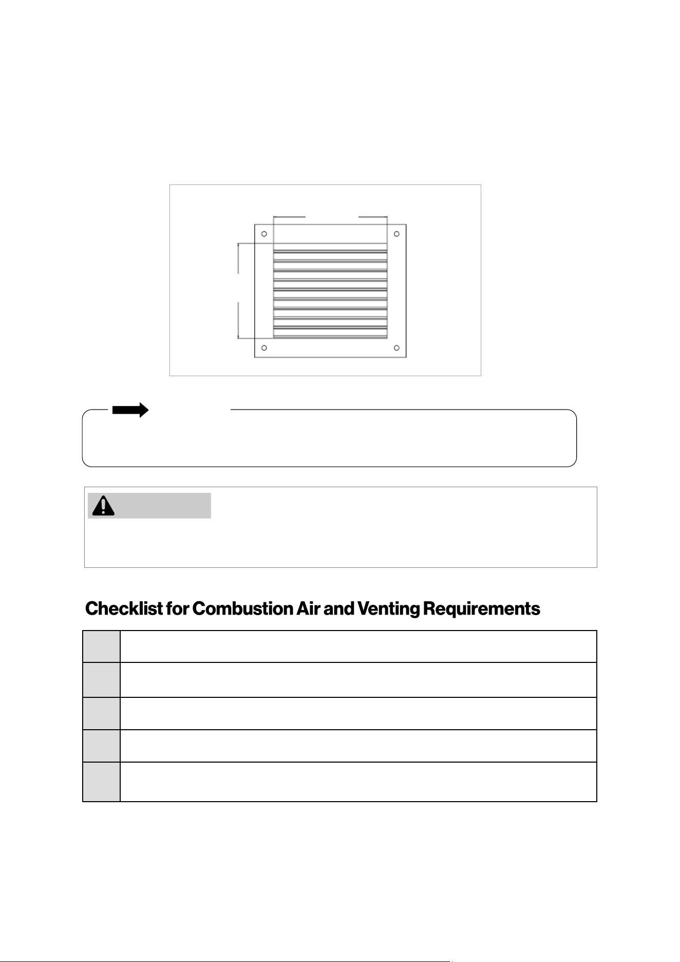
Rinnai Commercial Boiler Installation and Operation Manual 45
Combuson air provided to the appliance should not be taken from any area of the structure that
may produce a negave pressure (i.e. exhaust fans, powered venlaon fans).
Locaon
To maintain proper circulaon of combuson air two permanent openings (one upper, one lower) must be
posioned in conned spaces. The upper shall be within 12 in. (0.30 m) of the top of the
conned space and the lower opening shall be within 12 in. (0.30 m) of the boom of the conned space.
Openings must be posioned as to never be obstructed.
12 in.
(300 mm)
10 in.
(250 mm)
□
Verify all combuson air opening sizes are correct.
□
Ensure that the Combuson Air Requirements are followed that will provide sucient combuson
air for the appliance.
□
DO NOT use room air for combuson in applicaons where the indoor air is corrosive.
□
Verify that adequate combuson air is available for all appliances installed in the space.
□
Installaon complies with Naonal Fuel Gas Code, ANSI Z223.1/NFPA 54 as well as local and state
regulaons therein.
To prevent possible personal injury or death due to asphyxiaon, common venng with other
manufacturer’s induced dra appliances is not allowed.
IMPORTANT
Figure 33
WARNING
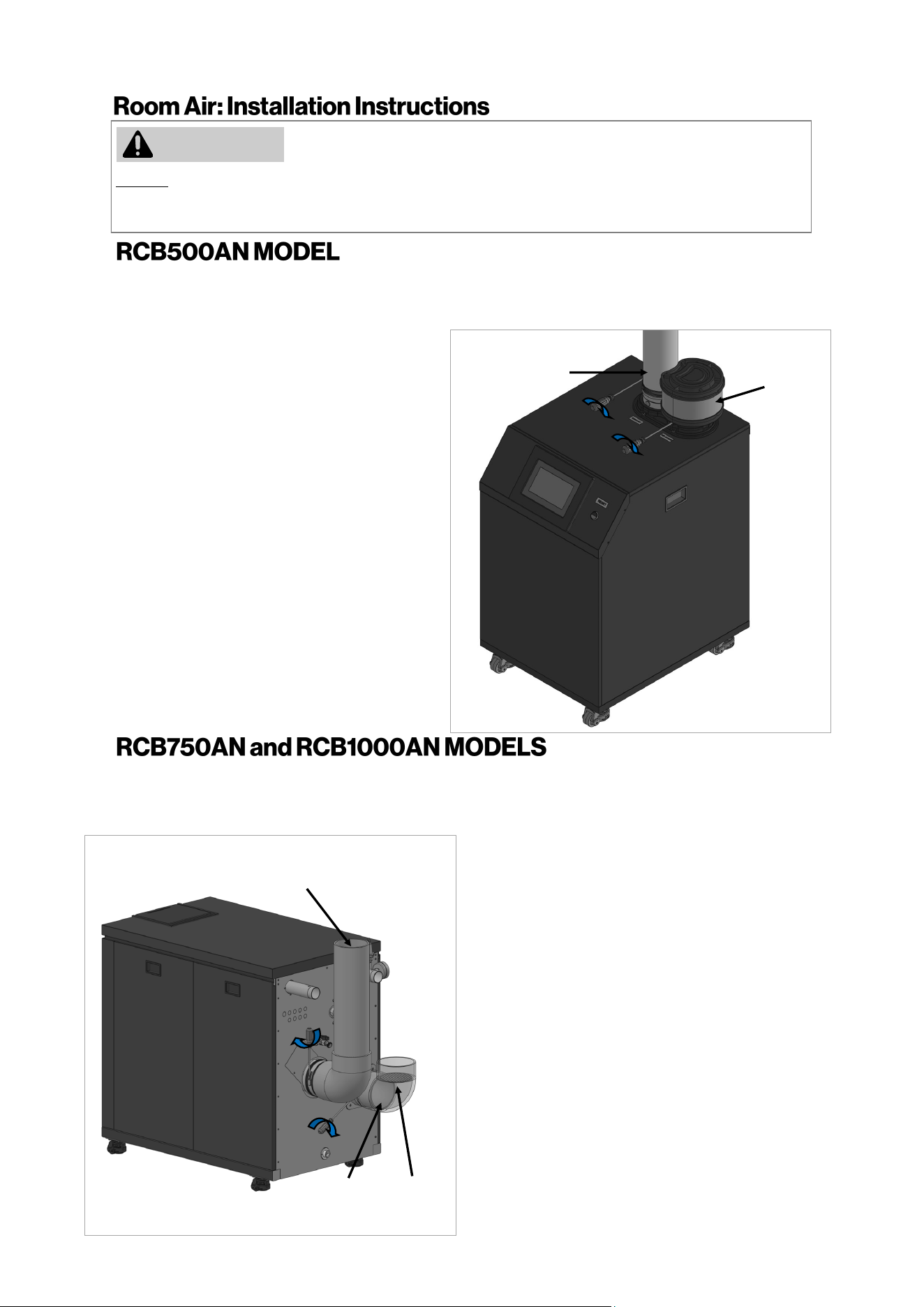
46 Rinnai Commercial Boiler Installation and Operation Manual
DO NOT apply PVC glues, solvents, or cleaners to the boiler’s combuson air or exhaust gasket connecons.
Failure to correctly assemble the components according to these instrucons may result in property damage,
personal injury, or death.
1.
Exhaust Pipe: Align and slide down PVC/
CPVC pipe on the exhaust vent connecon.
NOTE: Ensure that the pipe passes through
the rubber gasket on the metal vent adapter
and also hits a stop on the vent connecon.
2.
To secure the exhaust air vent pipe, ghten
the clamp aached on exhaust air vent using
a screwdriver.
WARNING
Intake Screen
(Not Supplied)
Exhaust Vent
Pipe
3.
Air Intake: Secure the oponal intake
screen to the intake connecon using 3
screws (supplied with appliance).
1.
Exhaust Pipe: Align and insert the PVC/CPVC
pipe on the exhaust vent connecon.
NOTE: Ensure that the pipe passes through the
rubber gasket on the metal vent adapter and
also hits a stop on the vent connecon.
4.
2.
Secure the pipe to the intake air adapter
using 3 screws (supplied with appliance).
To secure the exhaust air vent pipe, ghten
the clamp aached on exhaust air vent using
a screwdriver.
3.
Air Intake: Align and insert the PVC/CPVC
pipe on the air intake connecon unl it hits
a stop.
Mesh
Screen
Exhaust Vent
Pipe
The intake and exhaust adapters on top of the appliance are designed to t 4 Inch PVC/CPVC pipe. When
using other vent materials such as PP and Stainless Steel pipes ensure to use an appliance adapter from the
pipe manufacturer to properly connect to the boiler adapters.
The intake and exhaust adapters on back of the appliance are designed to t 6 Inch PVC/CPVC pipe. When
using other vent materials such as PP and Stainless Steel pipes ensure to use an appliance adapter from the
pipe manufacturer to properly connect to the boiler adapters.
Combuson
Air Pipe
5.
Install a mesh screen on the intake pipe to
prevent large debris from entering the
combuson chamber
Figure 35
Figure 34
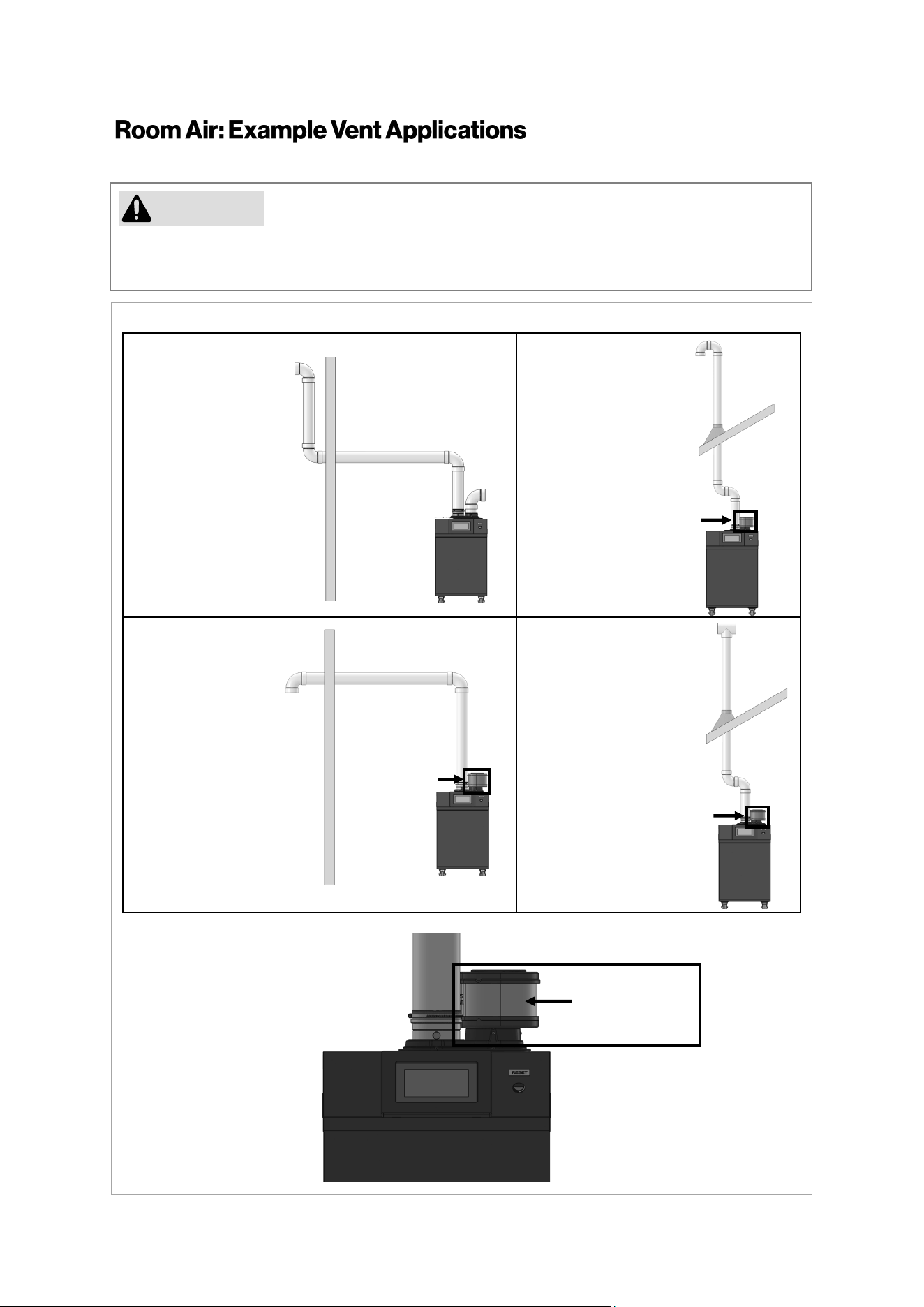
Rinnai Commercial Boiler Installation and Operation Manual 47
Rinnai cauons against installing the boiler in applicaons with venng in dierent pressure planes.
It is possible to have poor performance with this installaon.
CAUTION
Schedule 40
PVC/CPVC Snorkel
Terminaon
Conguraon
Schedule 40
PVC/CPVC Standard
Upside Down "U"
Vercal Terminaon
Conguraon
Schedule 40
PVC/CPVC Elbow or
Tee Side Wall
Terminaon
Conguraon
Schedule 40
PVC/CPVC Tee
Vercal Terminaon
Conguraon
Figure 36
Air Inlet Filter
(Oponal)
Enlarged view of oponal air inlet lter.
Air Inlet Filter
(Oponal)
Air Inlet Filter
(Oponal)
Air Inlet Filter
(Oponal)
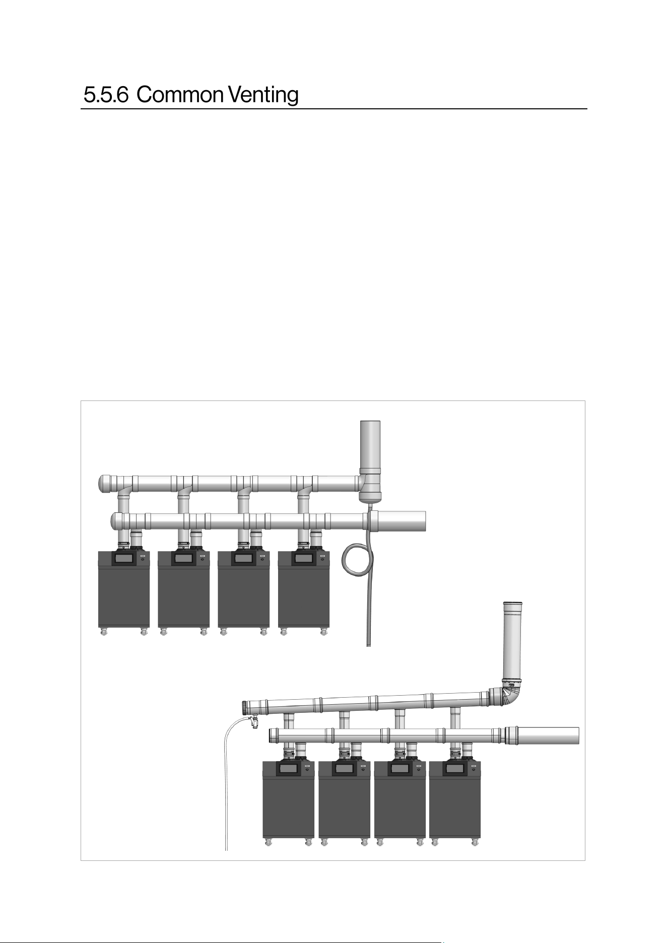
48 Rinnai Commercial Boiler Installation and Operation Manual
A maximum of four (4) RCB500AN Rinnai Commercial Boilers can be common vented. A maximum
of two (2) RCB750AN or RCB1000AN Rinnai Commercial Boilers can be common vented.Follow the
following guidelines to assure safe operaon:
1. Only common vent boiler of the same size and DO NOT exceed a maximum number of units
listed above.
2. DO NOT common vent Rinnai Commercial Boilers with other manufacturer’s products or other
models from Rinnai.
3. When common venng units, they must be wired and set-up to work as cascade.
4. Common venng system can be vented vercally or horizontally using direct vent or power
vent.
For detailed informaon about common venng including vent header size, approved venng, and
vent run, refer to separate “Rinnai Commercial Boiler Common Venng Installaon Instrucons” or
contact Rinnai.
Figure 37 (RCB500AN model shown)
Polypropylene (PP)
PVC / CPVC
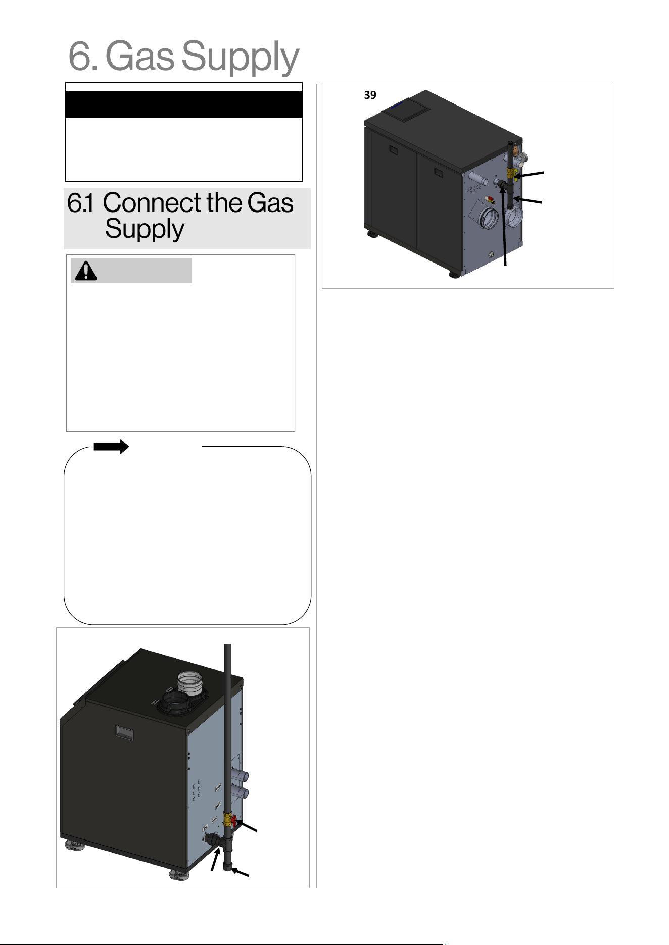
Rinnai Commercial Boiler Installation and Operation Manual 49
• The boiler shall be installed such that the
gas ignition system components are
protected from water (dripping,
spraying, rain, etc.) during appliance
operation and service (circulator
replacement, condensate trap, control
replacement, etc.).
• A sediment trap must be provided
upstream of the gas controls.
• A manual gas shutoff valve between the
gas supply and the boiler must be
installed.
• A licensed professional must install the
gas supply.
• Turn off 120V power supply.
• Turn off the gas.
• Gas is flammable. Do not smoke or
provide other ignition sources while
working with gas.
• Do not turn on the boiler or gas until all
fumes are gone.
Topics in this section
• Connect the Gas Supply
• Gas Operating Instructions
• Gas Pipe Sizing Reference Tables
IMPORTANT
1. Check the type of gas and gas supply pressure before
connecting the boiler. If the boiler is not of the gas
type that the building is supplied with, converting the
gas type of the boiler is necessary. A gas conversion kit
is available and can be purchased as an accessory.
Remove the Gas connection cap from the gas pipe
connection on the boiler before connecting the gas
supply piping.
2. Check the gas supply pressure immediately upstream
at a location provided by the gas company. Supplied
gas pressure must be within the limits shown below:
Natural Gas: 3.5 in. - 10.5 in. wc (0.87 - 2.61 kPa)
Propane Gas: 8.0 in. - 13.5 in. wc (1.99 - 3.36 kPa)
Maximum gas pressure checked with no flow (lockup)
or with boiler on.
Minimum pressure checked with gas flowing and unit
running at 100% of the firing rate.
3. Before placing the appliance in operation, all joints
including the heater must be checked for gas tightness
by means of soap, gas leak detector solution, or an
equivalent nonflammable solution, as applicable.
Since some leak test solutions, including soap and
water, may cause corrosion or stress cracking, the
piping shall be rinsed with water after testing, unless it
has been determined that the leak test solution is
non-corrosive.
4. Use approved and appropriately sized connectors to
connect the boiler to the gas line. Purge the gas line of
any debris before connection to the boiler.
5. Any compound used on the threaded joint of the gas
piping shall be a type that resists the action of
liquefied petroleum gas (propane/LPG).
6. The gas supply line shall be gas tight, sized, and so
installed as to provide a supply of gas sufficient to
meet the maximum demand of the heater and all
other gas consuming appliances at the location
without loss of pressure. If in doubt about the size of
the gas line, refer to section “6.3 Gas Pipe Sizing
Reference Tables.”
7. Perform a leak and pressure test prior to operating
the boiler. If a leak is detected, do not operate the
boiler until the leak is repaired.
Figure 39
Figure 38
Union
WARNING
Gas Shut Off
Valve
Sediment
trap (drip leg)
Union
Gas Shut Off
Valve
Sediment
trap (drip leg)
50 Rinnai Commercial Boiler Installation and Operation Manual
WARNING: If you do not follow these instructions EXACTLY, a fire or explosion may
result causing property damage, personal injury or loss of life.
A This appliance does not have a pilot. It is equipped with an ignition device which
automatically lights the burner. Do not try to light the burner by hand.
B BEFORE OPERATING smell all around the appliance area for gas. Be sure to smell next to
the floor because some gas is heavier than air and will settle on the floor.
WHAT TO DO IF YOU SMELL GAS:
• DO NOT try to light any appliance.
• DO NOT touch any electric switch; DO NOT use any phone in your building.
• Immediately call your gas supplier from a neighbor’s phone. Follow the gas
supplier’s instructions.
• If you cannot reach your gas supplier, call the fire department.
C Use only your hand to turn the gas control valve. Never use tools. If the gas control valve
will not turn by hand, don’t try to repair it, call a qualified service technician. Force or
attempted repair may result in a fire or explosion.
D Do not use this appliance if any part has been under water. Immediately call a qualified
service technician to inspect the appliance and to replace any part of the control system
and any gas control which has been under water.
1. Set the temperature controller to the lowest setting.
2. Turn off all electric power to the appliance if service is to be performed.
3. Turn the manual gas control valve located at gas inlet of appliance clockwise to the
OFF position.
TO TURN OFF GAS TO APPLIANCE
1. STOP! Read the safety information above on this label.
2. Set the temperature controller to lowest setting.
3. Turn off all electric power to the appliance.
4. This appliance does not have a pilot. It is equipped with a direct ignition device which
automatically lights the burner. DO NOT try to light the burner by hand.
5. Turn the manual gas control valve located at gas inlet of appliance clockwise to the
OFF position.
6. Wait five (5) minutes to clear out any gas. Then smell for gas, including near the floor. If
you smell gas, STOP! Follow “B” in the safety information above on this label. If you don’t
smell gas, go to the next step.
7. Turn the manual gas control valve located at gas inlet of appliance counterclockwise
to the ON position.
8. Turn on all electric power to the appliance.
9. Set the temperature controller to desired setting.
10. If the appliance will not operate, follow the instructions “To Turn Off Gas To Appliance”
and call your service technician or gas supplier.
OPERATING INSTRUCTIONS
FOR YOUR SAFETY READ BEFORE OPERATING
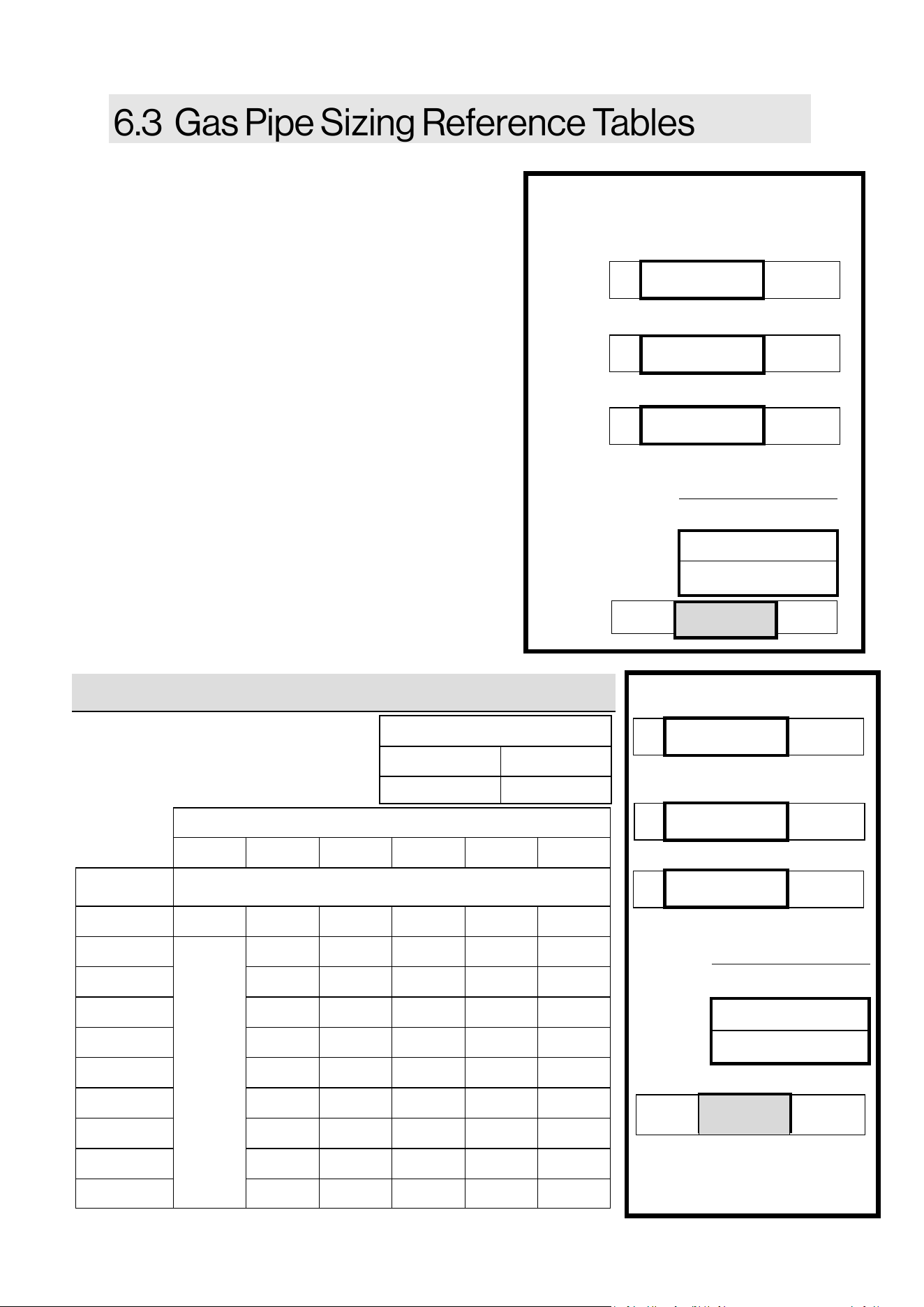
Rinnai Commercial Boiler Installation and Operation Manual 51
The gas supply must be capable of handling the enre
gas load required at the locaon. Gas line sizing is
based on gas type, the pressure drop in the system,
the gas pressure supplied, and gas line type. For gas
pipe sizing, refer to the Naonal Fuel Gas Code, ANSI
Z223.1/NFPA 54, or the Natural Gas and Propane
Installaon Code, CSA B149.1
For some tables, you will need to determine the cubic
feet per hour of gas required by dividing the gas input
by the heang value of the gas (available from the
local gas company). The gas input needs to include all
gas products at the locaon and the maximum Btu
usage at full load when all gas products are in use.
Use the table for your gas type and pipe type to nd
the pipe size required. The pipe size must be able to
provide the required cubic feet per hour of gas or the
required Btu/hr.
The informaon below is provided as an example. The
appropriate table from the applicable code must be
used.
Pressure Drop 0.5 in. w.c.
EXAMPLE
Rinnai Model Gas Input:
Addional Appliance Total Gas
Input:
Heang Value of Gas:
Cubic Feet Per Hour (CFH):
ANSWER:
B
100,000
Btu/hr
C
1,000
Btu/
3
A
1,000,000
Btu/hr
1,000,000+100,000
(CFH) =
1000
1,100
FT
3
/HR
CFH =
For this example, the pipe
diameter must be at least 1-1/2
in. pipe size and maximum 30
(9 m) in length.
A + B
(CFH) =
C
Instrucons: Enter values in empty boxes.
Rinnai Model Gas Input:
Addional Appliance Total Gas Input:
Heang Value of Gas:
Cubic Feet Per Hour (CFH):
ANSWER:
B
Btu/hr
C
Btu/
3
A
Btu/hr
(CFH) =
FT
3
/HR CFH =
A + B
(CFH) =
C
GAS PIPE SIZING CALCULATION WORKSHEET
Natural Gas
Schedule 40 Metallic Pipe
Inlet Pressure: Less than 2 psi
Specic Gravity: 0.60
Informaon in table obtained
from NFPA 54, ANSI Z223.1.
Nominal Pipe Size (in.)
1 1 1/4 1 1/2 2 2 1/2 3
Length in Capacity in Cubic Feet of Gas per Hour
10 (3) 678 1,390 2,090 4,020 6,400 11,300
20 (6) 957 1,430 2,760
N/A
44,00 7,780
30 (9) 768 1,150 2,220 3,530 6,250
40 (12) 657 985 1,900 3,020 5,350
50 (15) 583 873 1,680 2,680 4,740
60 (18) 528 791 1,520 2,430 4,290
70 (21) 486 728 1,400 2,230 3,950
80 (24) 452 677 1,300 2,080 3,670
90 (27) 424 635 1,220 1,950 3,450
100 (30) 400 600 1,160 1,840 3,260
Gas Pipe Sizing Reference Table
Table 25
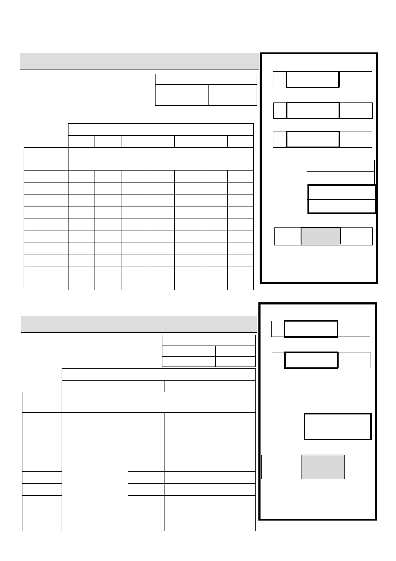
52 Rinnai Commercial Boiler Installation and Operation Manual
EXAMPLE
Rinnai Model Gas Input:
Addional Appliance Total Gas Input:
Total Gas Input:
ANSWER:
= Btu/hr
Total Gas
Input
1,100,000
EXAMPLE
Rinnai Model Gas Input:
Addional Appliance total Gas Input:
Heang Value of Gas:
Cubic Feet Per Hour (CFH):
ANSWER:
B
100,000
Btu/hr
C
1,000
Btu/
3
A
1,000,000
Btu/hr
1,000,000+100,000
(CFH) =
1000
1,100
3
/HR
CFH =
For this example, the pipe diameter
must be at least 1 in. nominal pipe
size and maximum 20 (6 m) in
length.
A + B
(CFH) =
C
B
100,000
Btu/hr
A
1,000,000
Btu/hr
For this example, the pipe diameter
must be at least 1-1/4 in. nominal
pipe size and maximum 40 (12 m)
in length.
Total
Gas
Input
= A + B
Total
Gas
Input
=
300,000+100,000
Pressure Drop 0.5 in. w.c.
Nominal Inside Pipe Size (in.)
3/4 1 1 1/4 1-1/2 2 2-1/2
Length in
(meters)
Capacity in Thousands of Btu/hr
10 (3) 608 1,150 2,350 3,520 6,790 10,800
20 (6)
N/A
787 1,620 2,420 4,660 7,430
30 (9) 632 1,300 1,940 3,750 5,970
40 (12) 541 1,110 1,660 3,210 5,110
50 (15) 985 1,480 2,840
N/A
4,530
60 (18) 892 1,340 2,570 4,100
70 (21) 821 1,230 2,370 3,770
80 (24) 763 1,140 2,200 3,510
90 (27) 716 1,070 2,070 3,290
100 (30) 677 1,010 1,950 3,110
Pressure Drop 3.0 in. w.c.
Schedule 40 Metallic Pipe
Inlet Pressure: Less than 2 psi
Specic Gravity: 0.6
Nominal Pipe Size (in.)
3/4 1 1 1/4 1-1/2 2 2-1/2 3
Length in
(meters)
Capacity in Cubic Feet of Gas per Hour
10 (3)
949 1,790 3,670 1,580 3,050 4,680 8,580
20 (6)
652 1,230 2,520 1,090 2,090 3,340 5,900
30 (9)
524 986 2,030 873 1,680 2,680 4,740
40 (12)
448 844 1,730 747 1,440 2,290 4,050
50 (15)
397 748 1,540 662 1,280 2,030 3,590
60 (18)
360 678 1,390 600 1,160 1,840 3,260
70 (21)
331 624 1,280 552 1,060 1,690 3,000
80 (24)
308 580 1,190 514 989 1,580 2,790
90 (27)
N/A
544 1,120 482 928 1,480 2,610
100 (30)
514 1,060 455 877 1,400 2,470
Informaon in table obtained from
NFPA 54, ANSI Z223.1.
Informaon in table obtained from
NFPA 54, ANSI Z223.1.
Intended use: Inial supply pressure
of 8.0 in. w.c. or greater.
Schedule 40 Metallic Pipe
Inlet Pressure: 11 in. w.c.
Specic Gravity: 1.50
Natural Gas
Propane (Undiluted)
Gas Pipe Sizing Reference Table
Gas Pipe Sizing Reference Table
Table 27
Table 26
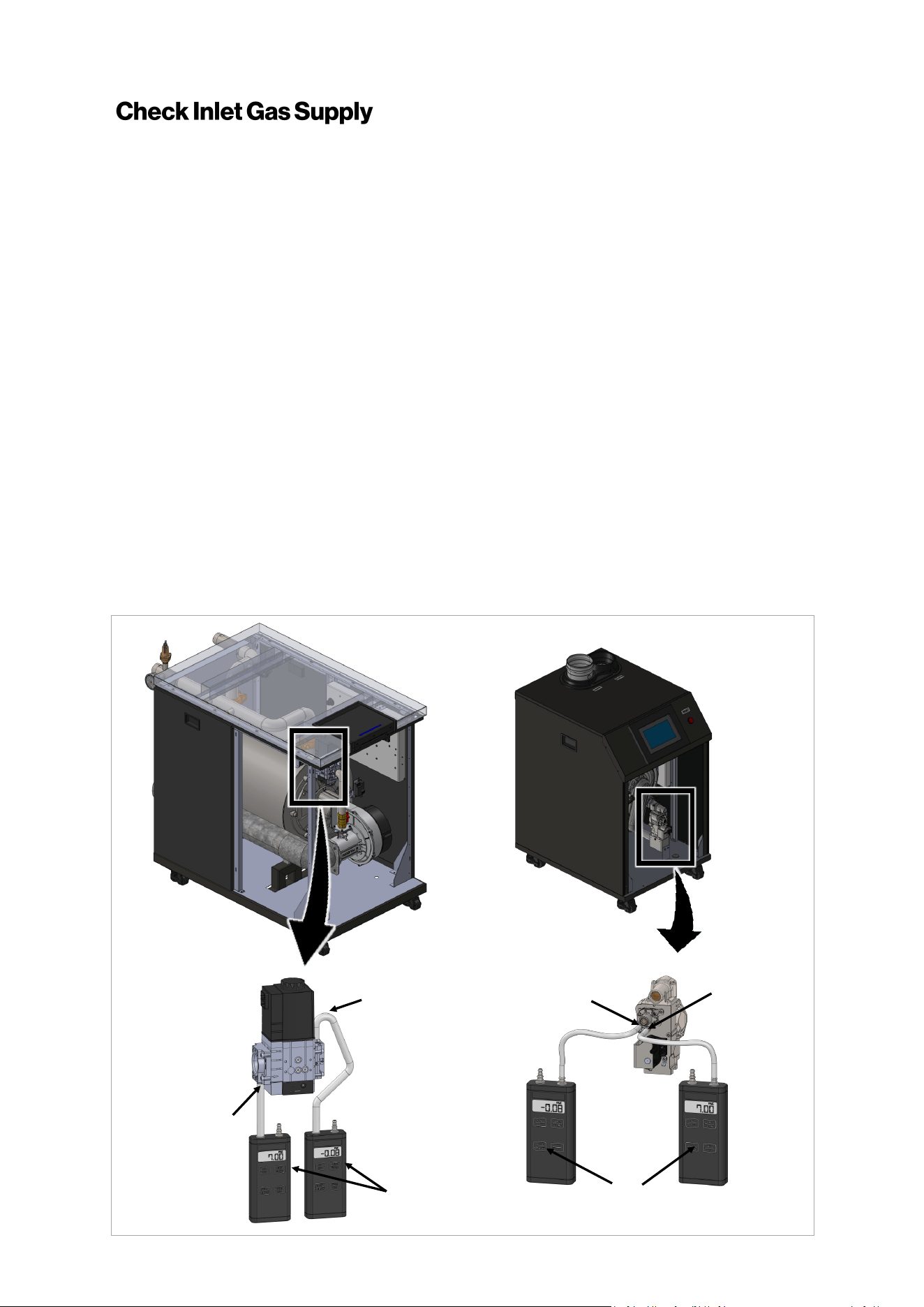
Rinnai Commercial Boiler Installation and Operation Manual 53
The gas piping must be sized for the proper flow and length of pipe, to avoid excessive pressure
drop. Both the gas meter and the gas regulator must be properly sized for the total gas load. If you
experience a pressure drop greater than 1 inch w.c. (249 Pa), the meter, regulator, or gas line is
undersized or in need of service. Perform the steps below when checking inlet gas supply:
1. Turn OFF the electrical power to the unit.
2. Shut off the gas supply at the manual gas valve in the gas piping to the appliance.
3. Remove the front panel as shown in front panel removal instructions (see section “14.
Appendices”). Place the front panel in a safe place where it can not be damaged.
4. Locate the gas valve inlet measurement port (see figure below).
500 model: Use a Torx T-10 driver to undo the screw a half turn.
750 and 1000 models: Use a small flat head screw driver to undo the screw a half turn.
5. Slip a tube over the nipple and connect to a manometer (pressure taps have a 0.35” [9mm]
outer diameter).
6. Slowly turn ON the gas supply at the manual gas valve.
7. Restore the electrical power to the unit.
8. Use the boiler controller to adjust the temperature setpoint and call for heat.
9. Observe the gas supply pressure as the unit fires at 100% of the input rate. Percent Boiler
modulation (percentage) will be displayed on the home screen of the unit.
10. Ensure the inlet pressure is within the specified range. Minimum and maximum gas supply
pressures are specified in this section of the manual. If the gas pressure is out of range, contact
the gas utility, gas supplier, qualified installer or service agency to determine the necessary
steps to provide proper gas pressure to the control.
11. Turn OFF the electrical power to the unit.
12. Shut off the gas supply at the manual gas valve in the gas piping to the appliance.
13. Remove the manometer from the pressure tap located on the gas valve. Ensure that the screw
is closed and leak tight after the testing (Torque: 0.9 - 8.9 Lb-in [0.1 - 1 Nm]).
Manifold
Pressure Port
Inlet
Pressure
Port
Manometer
Manifold
Pressure Port
Inlet
Pressure
Port
Manometer
Figure 40
RCB500AN RCB750AN/RCB1000AN
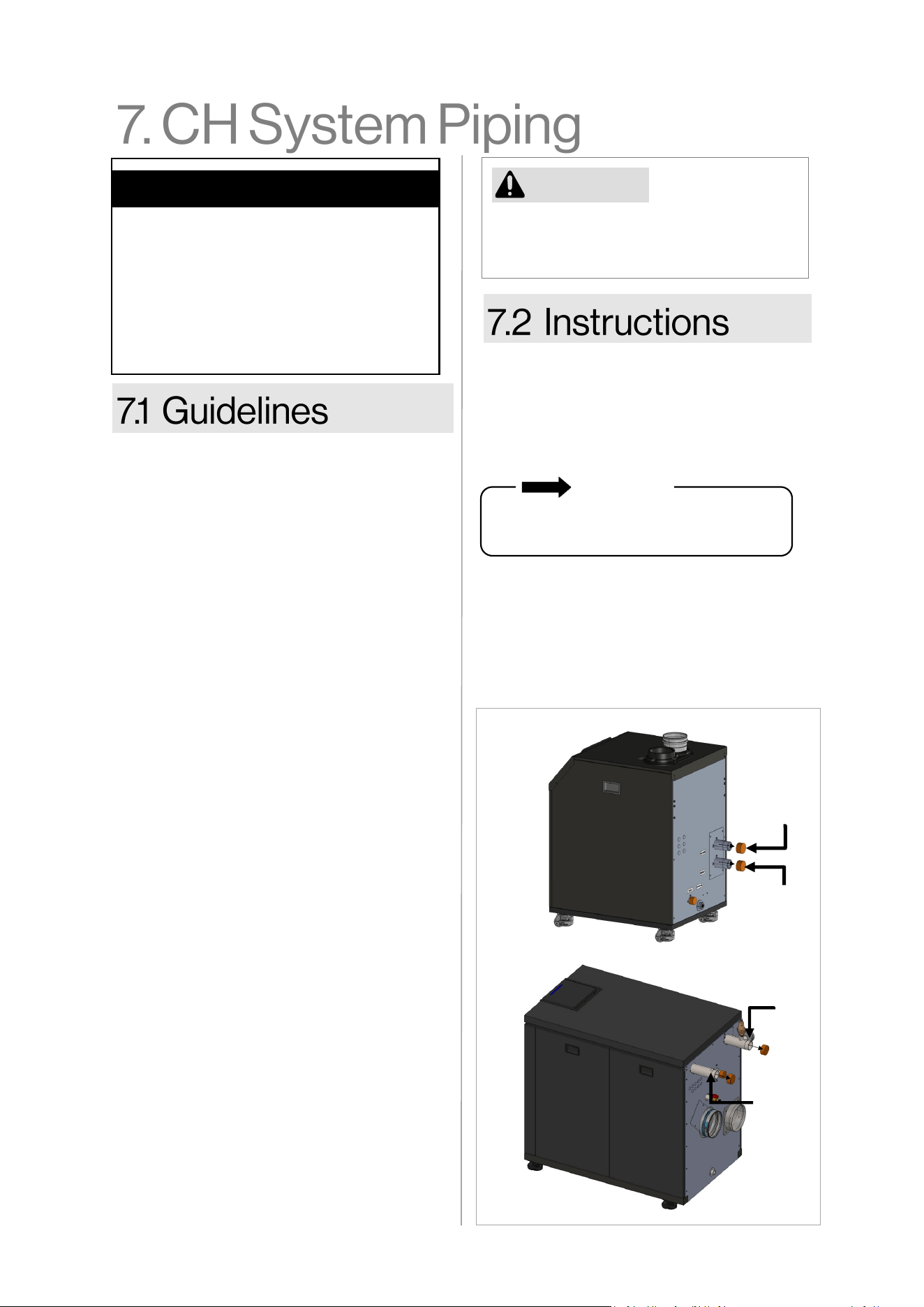
54 Rinnai Commercial Boiler Installation and Operation Manual
• This boiler is designed to work in a
closed loop system with pressure no less
than 14.5 psi (100 kPa). NOTE: Non-
metallic system piping must have an
oxygen barrier to be considered a closed
loop.
• Purge the heang system to remove all
debris and air. Debris and air in the lines
will damage the boiler.
• When removing the plasc sealing caps
from the boiler connecons, water may
come out of the boiler due to live re
tesng during manufacturing.
• The boiler, when used in connecon with
a refrigeraon system, must be installed
so the chilled medium is piped in parallel
with the boiler with appropriate valves
to prevent the chilled medium from
entering the boiler.
• The boiler piping system of a hot water
boiler connected to heang coils located
in air handling units where they may be
exposed to refrigerated air circulaon
must be equipped with ow control
valves or other automac means to
prevent gravity circulaon of the boiler
water during the cooling cycle.
• Some installaons with mulple zone
valves may require a dierenal bypass,
which will prevent excessively high ow
rates through a single zone when the
other zone valves are closed.
• It is required to include an air separator
on the central heang supply of the
system.
• System piping should be insulated when
freezing is a potenal concern.
• All piping must comply with local, state,
naonal or ASME code as appropriate.
To connect the water supply, follow the
instrucons below.
For standard installaons, refer to the “Piping
Diagram for Basic Central Heang
Installaon” in this chapter.
Remove the caps and plumb the heang
supply and return lines to the heang return
connecon on the boom of the boiler. The
return and supply connecons are 1-1/2”
NPT for the RCB500AN model and 2” NPT to
RCB750AN and RCB1000AN models.
CAUTION
• Guidelines
• Instrucons
• Common CH Components
• Hydraulic Separaon
• Connect the Pressure Relief Valves
• Connect the Condensate Drain Line
Topics in this secon
The boiler may not be installed directly to
a heang system where polybutylene or
other oxygen permeable piping is used.
Water connecons to the boiler should
follow all state and local plumbing codes.
IMPORTANT
Figure 41
SUPPLY
RETURN
RETURN
SUPPLY
RCB500AN
RCB750AN/RCB1000AN
Rinnai Commercial Boiler Installation and Operation Manual 55
Listed below are common components in a
Central Heang system. Refer to the diagram
on the next page.
• Expansion Tank — A properly sized
expansion tank charged to 2 PSI (14 kPa)
below the cold system pressure is required
to limit pressure changes in the heang
system. When replacing an expansion tank,
consult the expansion tank manufacturer
for sizing. Size the expansion tank for the
required system volume and capacity
according to the expansion tank
manufacturer’s instrucons.
• Air Separator — An air separator is needed
on the central heang supply side of the
system to remove any air that may be
present in the piping.
• Pressure/Temperature Gauge — The
current pressure and temperature will
alternately be displayed on the boiler
control panel. An external temperature
and pressure gauge is recommended to be
installed on the boiler supply pipe.
• Pressure Relief Valve (PRV) — A PRV
located directly on the supply side of the
boiler is required. A 75 PSI (517 kPa) PRV is
supplied with the boiler. This boiler has a
high-temperature shut-o device built-in
as a standard safety feature. Therefore, a
“pressure only” relief valve is required. DO
NOT install a relief valve with a pressure
rang in excess of 75 psi (517 kPa) - the
maximum allowable operang pressure of
the boiler. The relief valve capacity must
exceed the BTU/H input capacity of the
boiler.
• Oxygen Eliminaon — The boiler may
only be installed in a pressurized closed-
loop heang system, free of air and
other impuries. If using oxygen
permeable tubing in the central heang
system, a plate heat exchanger is
necessary to isolate the tubing and
boiler.
• Low Water Cut O (LWCO) — This
boiler has a factory-installed pressure
sensor type LWCO. The boiler's internal
LWCO is not serviceable or adjustable.
Check your local codes to determine if a
LWCO is required and if this device
conforms to the local code. If a LWCO is
required to be installed, the probe must
be located higher than the minimum
safe water level. When a LWCO is
installed, it must be wired back to the
appropriate terminal on the boiler.
• Water Fill Valve — Maintains proper
water pressure in the central heang
circuit.
• Back Flow Preventer — Use a back ow
preventer in the lling circuit to the
appliance as required by local code.
• Dirt Trap — Protects the boiler from
debris in the plumbing system. It is
recommended to install dirt trap in a
retrot installaon to remove debris le
in the system.
• Magnec separator — This device is
recommended to be installed in a
retrot system containing cast iron and/
or steel pipe. It should be located in the
heang return line as close as possible
to the boiler.
• Boiler Circulator Pump — A properly
sized pump should be installed on the
return line pumping into the boiler. The
pump should be sized according to the
pressure losses of the boiler and the
related heang system.
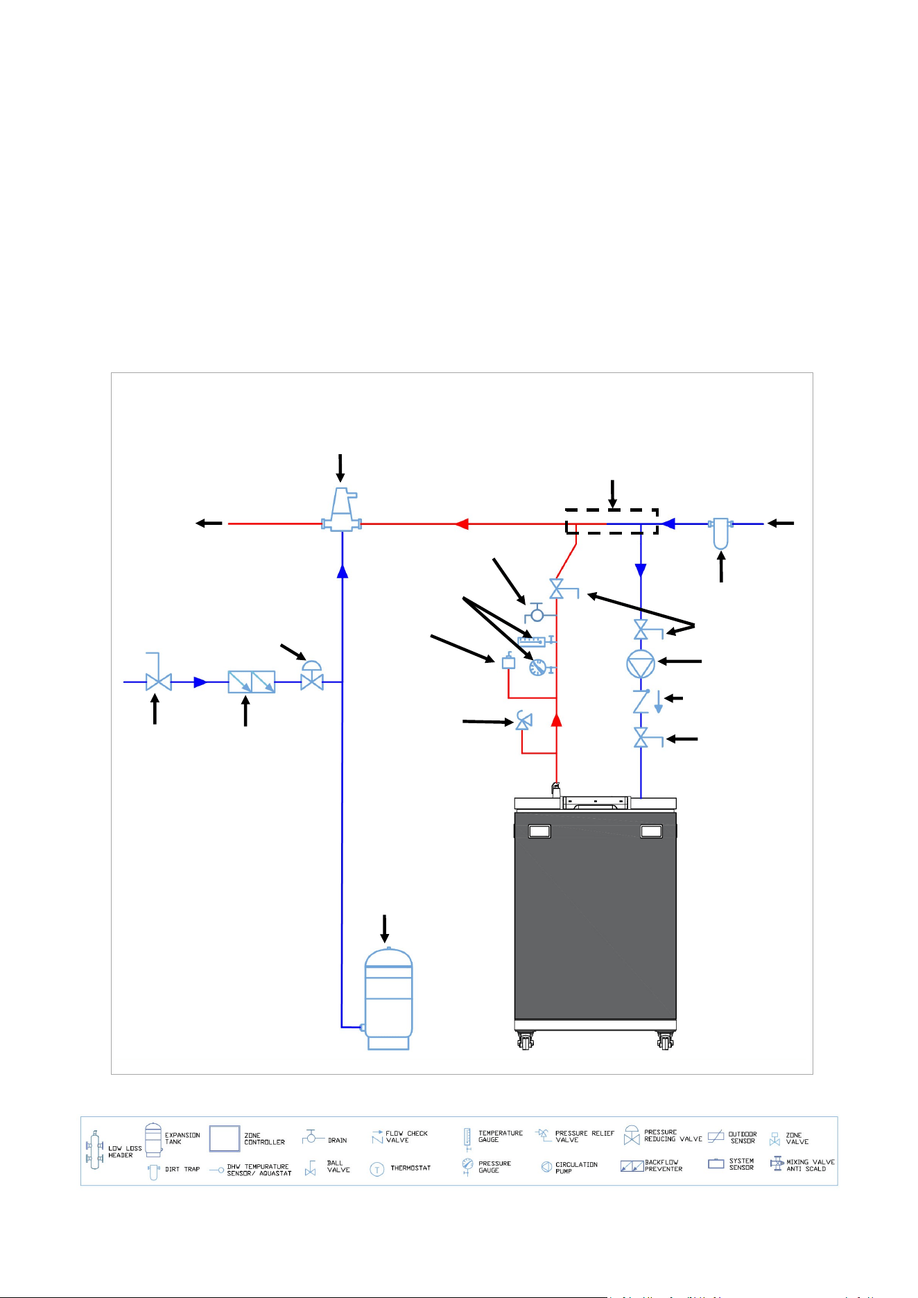
56 Rinnai Commercial Boiler Installation and Operation Manual
• Purge Valve - The boiler purge valve is
used to eliminate air from the system
during start-up.
• Boiler Isolaon Valves - Full port ball
valves must be used. Any other type of
valves may cause ow restricon to the
boiler.
Common CH Components Connued
CH System Common Components Diagram
• Boiler Piping - Boiler piping must be sized
properly to avoid unnecessary ow
reducon and poor boiler performance. The
minimum pipe size is 1-1/2 inch for
RCB500AN model and 2 Inch for RCB750AN
and RCB1000AN models.
• Flow Check Valve - Check valves are
important to prevent reverse ow condion
when the pump is not operang (o-cycle).
SYSTEM
RETURN
Pressure Relief
Valve (supplied
with boiler)
Closely spaced—tee
(may be substituted
with LLH)
Figure 42
Low Water
Cut Off
(if required by
local code)
Temperature &
Pressure Gauge
Purge Valve
SYSTEM
SUPPLY
Water fill valve
Backflow
Preventer
Ball Valve
Expansion tank
Air Separator
Dirt Trap
Isolation valve
Boiler Pump
Flow check valve
Isolation valve
Piping Diagram Symbols Legend
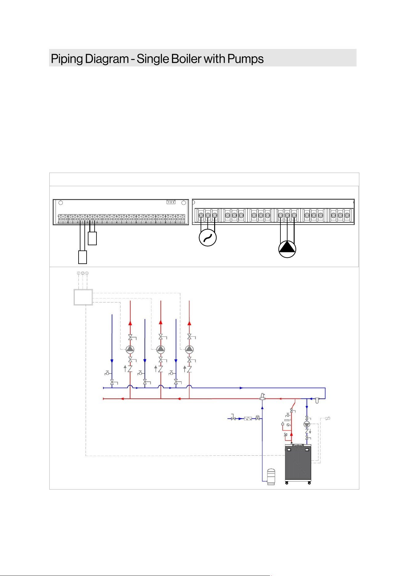
Rinnai Commercial Boiler Installation and Operation Manual 57
NOTES:
• Primary/Secondary piping must be used (closely spaced tees or low loss header).
• All closely spaced tees shall be within 4 pipe diameters center to center spacing.
• The minimum boiler piping must be at least 1-1/2 inch for RCB500AN model and 2 Inch for
RCB750AN and RCB1000AN models. Do not downsize boiler heang loop.
• It is recommended to use a check valve to prevent reverse ow and/or gravity circulaon when
pump is in o-cycle.
• Boiler pump must be properly sized to ensure proper ow rate through the boiler and related
piping. (minimum ow rate must be maintained to prevent short cycling)
• System ow rate should always be greater than boiler primary loop ow rate when the boiler is
in operaon to prevent short cycling.
This is not an engineering drawing; it is intended only as a guide and not as a replacement for professional
engineering project drawings. This drawing is not intended to describe a complete system. It is up to the
contractor or engineer to determine the necessary components and conguraon of the parcular system to
be installed. The drawing does not imply compliance with local building code requirements. It is the
responsibility of the contractor or engineer to ensure the installaon is in accordance with all local building
codes. Confer with local building ocials before installaon.
Figure 43
MAIN POWER
BOILER PUMP
POWER INPUT AUX 1 AUX 2 QX1 QX2 QX3
L N G L N G L N G L N G L N G L N G
BX1 B3-8 B9 H5 H4 H3 BX2 PWM UX2 UX3 H6-1 H6-2 H6-3
OUTDOOR SENSOR
ROOM THERMOSTAT 1
+ - + - + - + -
LOW VOLTAGE CONNECTION
HIGH VOLTAGE CONNECTION
ZONE
CONTROL
PANEL
OUTDOOR
SENSOR
ROOM
THERMOSTAT-1
BOILER
PUMP
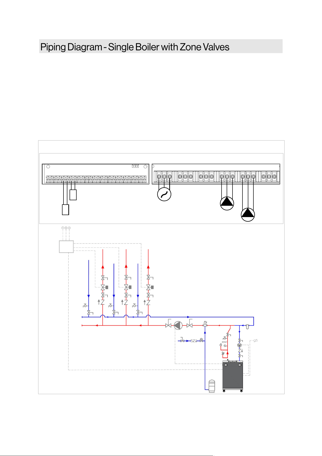
58 Rinnai Commercial Boiler Installation and Operation Manual
NOTES:
• Primary/Secondary piping must be used (closely spaced tees or low loss header).
• All closely spaced tees shall be within 4 pipe diameters center to center spacing.
• The minimum boiler piping must be at least 1-1/2 inch for RCB500AN model and 2 Inch for
RCB750AN and RCB1000AN models. Do not downsize boiler heang loop.
• It is recommended to use a check valve to prevent reverse ow and/or gravity circulaon
when pump is in o-cycle.
• Boiler pump must be properly sized to ensure proper ow rate through the boiler and related
piping (minimum ow rate must be maintained to prevent short cycling)
• System ow rate should always be greater than boiler primary loop ow rate when the boiler
is in operaon to prevent short cycling.
Figure 44
This is not an engineering drawing; it is intended only as a guide and not as a replacement for professional
engineering project drawings. This drawing is not intended to describe a complete system. It is up to the
contractor or engineer to determine the necessary components and conguraon of the parcular system to
be installed. The drawing does not imply compliance with local building code requirements. It is the
responsibility of the contractor or engineer to ensure the installaon is in accordance with all local building
codes. Confer with local building ocials before installaon.
ZONE
CONTROL
PANEL
OUTDOOR
SENSOR
ROOM
THERMOSTAT-1
BOILER
PUMP
MAIN POWER
BOILER PUMP
CH PUMP
POWER INPUT AUX 1 AUX 2 QX1 QX2 QX3
L N G L N G L N G L N G L N G L N G
BX1 B3-8 B9 H5 H4 H3 BX2 PWM UX2 UX3 H6-1 H6-2 H6-3
OUTDOOR SENSOR
ROOM THERMOSTAT 1
+ - + - + - + -
LOW VOLTAGE CONNECTION
HIGH VOLTAGE CONNECTION
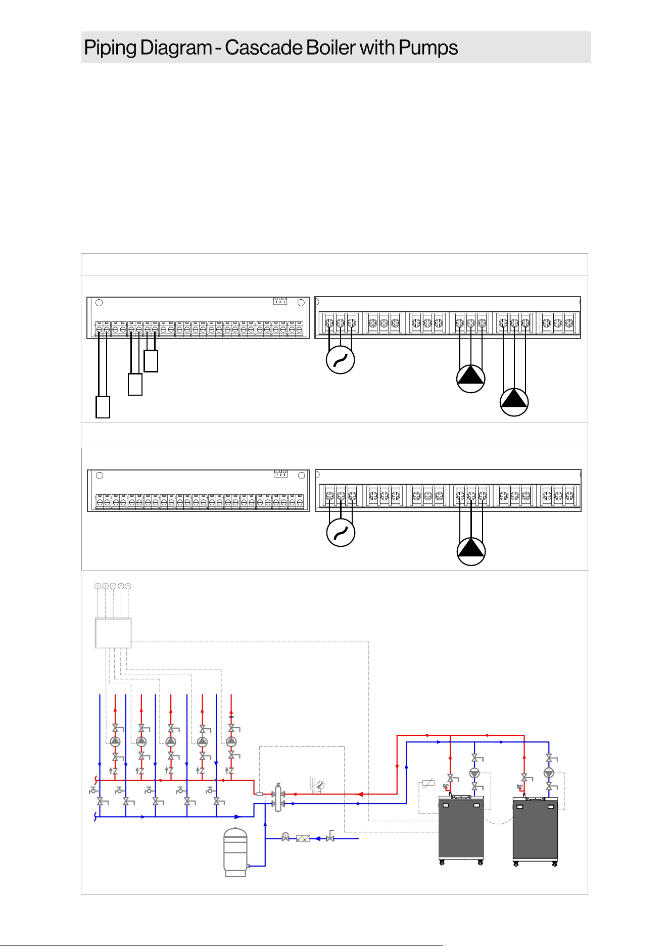
Rinnai Commercial Boiler Installation and Operation Manual 59
Figure 45
MAIN POWER
BOILER PUMP
CH PUMP
POWER INPUT AUX 1 AUX 2 QX1 QX2 QX3
L N G L N G L N G L N G L N G L N G
BX1 B3-8 B9 H5 H4 H3 BX2 PWM UX2 UX3 H6-1 H6-2 H6-3
OUTDOOR SENSOR
ROOM THERMOSTAT 1
+ - + - + - + -
LOW VOLTAGE CONNECTION
HIGH VOLTAGE CONNECTION
CASCADE SYSTEM SENSOR
MAIN POWER
BOILER PUMP
POWER INPUT AUX 1 AUX 2 QX1 QX2 QX3
L N G L N G L N G L N G L N G L N G
BX1 B3-8 B9 H5 H4 H3 BX2 PWM UX2 UX3 H6-1 H6-2 H6-3
+ - + - + - + -
LOW VOLTAGE CONNECTION
HIGH VOLTAGE CONNECTION
MASTER UNIT
FOLLOWER UNIT
ZONE
CONTROL
PANEL
OUTDOOR
SENSOR
ROOM
THERMOSTAT-1
BOILER
PUMP
BOILER
PUMP
MASTER FOLLOWER
CASCADE SYSTEM
SENSOR
This is not an engineering drawing; it is intended
only as a guide and not as a replacement for
professional engineering project drawings. This
drawing is not intended to describe a complete
system. It is up to the contractor or engineer to
determine the necessary components and
conguraon of the parcular system to be
installed. The drawing does not imply
compliance with local building code
requirements. It is the responsibility of the
contractor or engineer to ensure the installaon
is in accordance with all local building codes.
Confer with local building ocials before
installaon.
NOTES:
• Primary/Secondary piping must be used (closely spaced tees or low loss header).
• All closely spaced tees shall be within 4 pipe diameters center to center spacing.
• The minimum boiler piping must be at least 1-1/2 inch for RCB500AN model and 2 Inch for
RCB750AN and RCB1000AN models. Do not downsize boiler heang loop.
• It is recommended to use a check valve to prevent reverse ow and/or gravity circulaon when
pump is in o-cycle.
• Boiler pump must be properly sized to ensure proper ow rate through the boiler and related
piping (minimum ow rate must be maintained to prevent short cycling)
• Indirect Water Heater Applicaon—Ensure boiler output does not exceed indirect water heater
transfer capability.
• System ow rate should always be greater than boiler primary loop ow rate when the boiler is
in operaon to prevent short cycling.
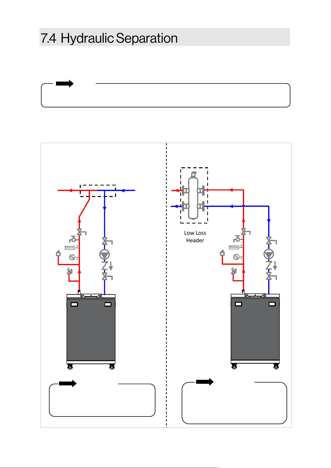
60 Rinnai Commercial Boiler Installation and Operation Manual
Rinnai requires the use of hydraulic separaon between the boiler and central heang system.
Hydraulic separaon and primary/secondary piping allow two or more circulators in a hydronic
system to operate independently, without interfering with ow in connecng piping circuits.
NOTE
Examples of Hydraulic Separaon
Closely spaced tees and low loss headers are common examples of hydraulic separators and are
used to separate the boiler loop from the central heang loop.
When Rinnai Commercial Boilers are in use with Rinnai air handlers, please reference the air
handler Installaon and Operaon Manual for installaon and performance details.
IMPORTANT
For closely spaced tee installations, the
separation at the header is to be no
more than four pipe diameters.
Low Loss
Header
Low Loss Header Primary/Secondary Piping
Closely spaced tees
IMPORTANT
If using a low loss header, install the
PRV and shut off valves between the
boiler and low loss header (as
illustrated in the above image).
Figure 46
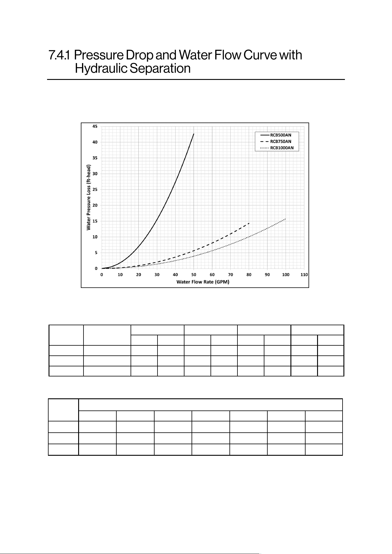
Rinnai Commercial Boiler Installation and Operation Manual 61
The Rinnai Commercial Boiler does not have an included boiler pump. An external boiler pump
must be installed and sized to the ow rate and pressure drop through the boiler, system piping,
and system components. Larger systems, or systems with large pressure drops, should incorporate
a form of hydraulic separaon, such as closely spaced tees or a low loss header.
Model
Minimum
Pipe Size
20°F 25°F 30°F
35°F
GPM Ft/Hd
GPM Ft/Hd
GPM Ft/Hd GPM Ft/Hd
RCB500 1-1/2 In.
49 41 39 22 32 17 28 13
RCB750 2 In.
73 12 58 8 49 6 42 4
RCB1000 2 In.
97 16 78 10 65 7 55 5
Model
Number of Units / Common Header Pipe Sizes (inches)
2 3 4 5 6 7 8
RCB500
3 4 4 4 5 5 6
RCB750
4 4 5 6 6 6 8
RCB1000
4 5 6 6 8 8 8
Recommended pipe sizing when using mulple units:
Circulator sizing informaon based on temperature rises:
Table 29: Pipe Sizing with Mulple Units
Table 28: Circulator Sizing Informaon
62 Rinnai Commercial Boiler Installation and Operation Manual
An approved pressure relief valve is required
by the American Naonal Standard (ANSI
Z21.13) and ASME Boiler and Pressure Vessel
Code, Secon IV (Heang Boilers) for all water
heang systems and shall be accessible for
servicing (an approved pressure relief valve is
supplied with the boiler). When connecng a
pressure relief valve, follow the guidelines
below:
• The pressure relief valve must comply with
the standard for Relief Valves and
Automac Gas Shuto Devices for Hot
Water Supply Systems ANSI Z21.22, the
standard Temperature, Pressure,
Temperature and Pressure Relief Valves
and Vacuum Relief Valves, CAN1-4.4, and/
or the ANSI/ASME Boiler and Pressure
Vessel Code, Secon IV (Heang Boilers).
• The pressure relief valve must be rated up
to 75 psi for central heang systems, and
to at least the maximum Btu/hr of the
appliance.
• The discharge from the pressure relief
valve should be piped to the ground or into
a drain system per local codes.
• The pressure relief valve must be manually
operated once a year to check for correct
operaon.
• The discharge line from the pressure relief
valve should pitch downward and
terminate 6 in. (152 mm) above drains
where discharge will be clearly visible.
Water discharged from the pressure relief
valve could cause severe burns instantly or
death from scalds.
• The discharge end of the line shall be plain
(unthreaded) and a minimum of 3/4 in.
nominal pipe diameter. The discharge line
material must be suitable for water at
least 180° Fahrenheit.
• If a pressure relief valve discharges
periodically, this may be due to thermal
expansion in a closed water supply system.
Contact the water supplier or local
plumbing inspector on how to correct this
situaon. Do not plug the pressure relief
valve.
• The American Naonal Standard (ANSI
Z21.13) does not require a combinaon
temperature and pressure relief valve for
this appliance. However, local codes may
require a combinaon temperature and
pressure relief valve.
• Protect pressure relief valve and pressure
relief valve discharge line from freezing.
Do not plug or restrict ow of the pressure
relief valve.
IMPORTANT
An ASME 75 psi safety pressure relief
valve is included with the boiler and must
be ed before any shut o valve in the
system.
• DO NOT plumb the pressure relief
valve with the condensate drain; both
must be plumbed independently to
drain.
• DO NOT plug the pressure relief valve
and do not install any reducing ngs
or other restricons in the relief line.
The pressure relief line should allow
for complete drainage of the valve
and the line.
• DO NOT place any other valve or
shuto device between the pressure
relief valve and the boiler.
WARNING
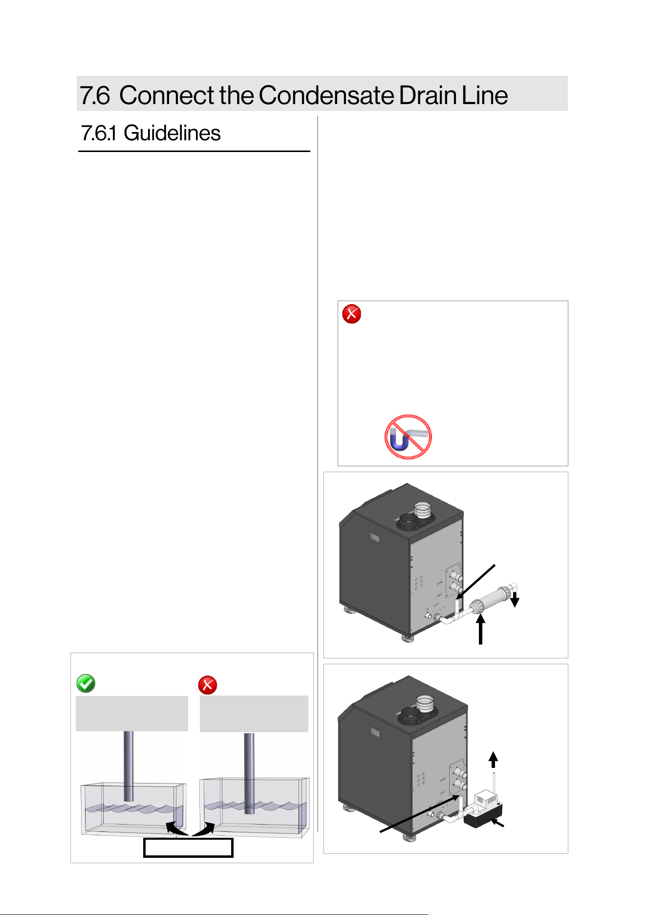
Rinnai Commercial Boiler Installation and Operation Manual 63
• Do not plumb the condensate drain with
the pressure relief valve; both must be
plumbed independently to drain.
• All condensate must drain and be
disposed of according to local codes.
• Use only corrosion resistant materials for
the condensate drain lines such as PVC
pipe or plasc hose.
• The condensate drain pipe (along its enre
length) must be at least 3/4 inches.
• The condensate drain pipe should be as
short as possible and have a downward
pitch.
• Condensaon drain lines installed in areas
that are subject to freezing temperatures
should be wrapped with an approved
supplemental heat source. Install per
manufacturer’s instrucons.
• Slope the condensate drain lines toward
the inside oor drain or condensate
pump.
• If the condensate drain pipe is closed or
stuck, the drain water will come out from
the side hole on the condensate drain pipe
connecon.
• The end of the condensate drain pipe
should be open to the atmosphere. The
end should not be under water or other
substances.
• If a oor drain is not available or the drain
is above the level of the condensate drain,
a condensate pump should be installed.
• Use a tee at the condensate connecon
with a branch vercally up and open to
atmosphere to prevent a vacuum that
could obstruct the ow of condensate
from the boiler.
CORRECT
Pipe open to
atmosphere
Pipe submerged
in water
NOT CORRECT
Water level
EXTERNAL TRAP
NOT REQUIRED
DO NOT
• DO NOT connect the condensate drain
line with an air condioning evaporator
coil drain.
• Boilers have an integrated condensate
trap. DO NOT install an external
condensate trap.
• A condensate neutralizer kit is available from
Rinnai. The kit allows condensate to ow
through neutralizing media that raises the pH
of the condensate to a level that will help
prevent corrosion of the drain and public
sewer system. Refer to secon “3.7 Included
Accessories” for more informaon.
• Before operaon of the boiler, the condensate
collector must be lled with water.
• Refer to neutralizer Installaon Manual and
local codes for neutralizer installaon
guidelines.
Figure 48
Figure 47
To Drain
Condensate
Drain Pump
Figure 49
Neutralizer
Open to
Atmosphere
To Drain
Open to
Atmosphere
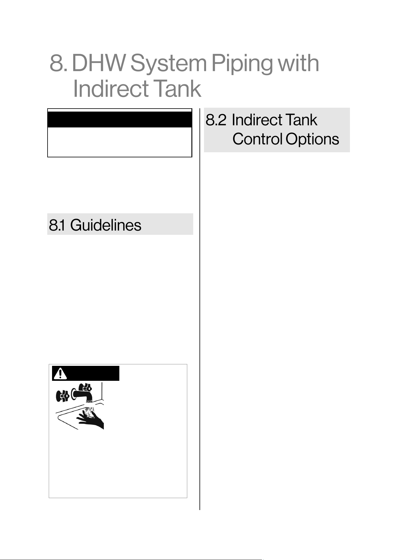
64 Rinnai Commercial Boiler Installation and Operation Manual
Topics in this secon
• Guidelines
• Indirect Tank Control Opons
• The piping (including soldering materials)
and components connected to this
appliance must be approved for use in
potable water systems.
• Purge the water line to remove all debris
and air. Debris will damage the boiler.
• DHW must not be connected to a system
that was previously used with a non-
potable water heang appliance.
• DO NOT introduce toxic chemicals such as
those used for boiler water treatment to
the potable water used for central heang
into the DHW system.
Hot water can cause rst degree burns
with exposure for as lile as:
• 3 seconds at 140°F (60°C)
• 20 seconds at 130°F (54°C)
• 8 minutes at 120°F (49°C)
Children, disabled, or elderly are at
highest risk of being scalded. Feel water
before bathing or showering.
Water temperatures
over 125° F (52° C)
can cause severe
burns or scalding
resulng in death.
DANGER
This boiler provides DHW through an indirect
tank. The boiler incorporates temperature
control features for the boiler and indirect
tank controls, including indirect tank heang
priority.
HOT
BURN
The indirect tank temperature is controlled
through either a thermistor (default) or
thermostat/aqua-stat.
• Thermistor (Default): The Indirect Tank
temperature setpoint range is 104°F to
176°F. Connect the thermistor to the low
voltage terminal labeled ‘DHW sensor’.
When a thermistor is connected, the boiler
will automacally recognize the
temperature in the tank. Once the setpoint
is selected, the boiler will automacally
calculate the supply temperature setpoint
in order to eciently sasfy the Indirect
Tank demand. The maximum boiler supply
temperature is 180°F (82°C). The higher
the supply temperature to the tank, the
quicker the tank will heat up.
• Thermostat: If thermostat control of the
tank is desired, the thermostat connects to
the low voltage terminal labeled ‘DHW
sensor’. Set the Indirect Setpoint to match
the seng of the Aqua-Stat mounted on
the tank. Once the setpoint is selected, the
boiler will automacally calculate the
supply temperature setpoint in order to
eciently sasfy the Indirect Tank
demand. The maximum boiler supply
temperature is 180°F (82°C). The higher
the supply temperature to the tank, the
quicker the tank will heat up.
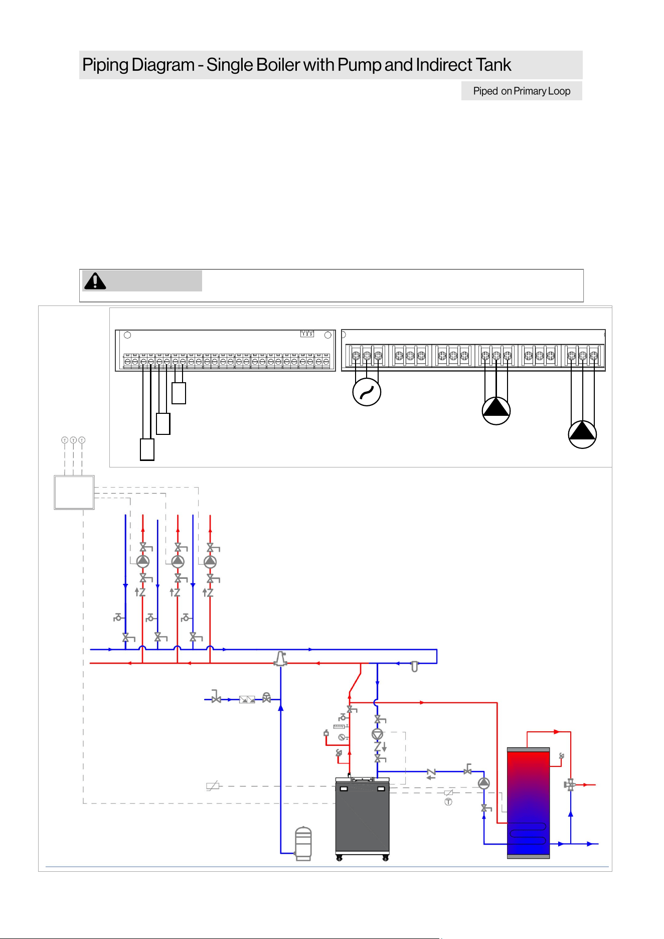
Rinnai Commercial Boiler Installation and Operation Manual 65
NOTES:
• Primary/Secondary piping must be used (closely spaced tees or low loss header).
• All closely spaced tees shall be within 4 pipe diameters center to center spacing.
• The minimum boiler piping must be at least 1-1/2 inch for RCB500AN model and 2 Inch for
RCB750AN and RCB1000AN models. Do not downsize boiler heang loop.
• It is recommended to use a check valve to prevent reverse ow and/or gravity circulaon when
pump is in o-cycle.
• Boiler pump must be properly sized to ensure proper ow rate through the boiler and related
piping (minimum ow rate must be maintained to prevent short cycling)
• Indirect Water Heater Applicaon—Ensure boiler output does not exceed indirect water heater
transfer capability.
• System ow rate should always be greater than boiler primary loop ow rate when the boiler is
in operaon to prevent short cycling.
WARNING
Low temperature heang zones must be protected with a mixing valve if
running simultaneous DHW and Central Heang.
This is not an engineering drawing; it is intended only as a guide and not
as a replacement for professional engineering project drawings. This
drawing is not intended to describe a complete system. It is up to the
contractor or engineer to determine the necessary components and
conguraon of the parcular system to be installed. The drawing does
not imply compliance with local building code requirements. It is the
responsibility of the contractor or engineer to ensure the installaon is in
accordance with all local building codes. Confer with local building
ocials before installaon.
+ - + - + - + -
MAIN POWER
BOILER PUMP
DHW PUMP
POWER INPUT AUX 1 AUX 2 QX1 QX2 QX3
L N G L N G L N G L N G L N G L N G
BX1 B3-8 B9 H5 H4 H3 BX2 PWM UX2 UX3 H6-1 H6-2 H6-3
OUTDOOR SENSOR
ROOM THERMOSTAT 1
+ - + - + - + -
LOW VOLTAGE CONNECTION
HIGH VOLTAGE CONNECTION
DHW SENSOR/AQUASTAT
Figure 50
ZONE
CONTROL
PANEL
OUTDOOR
SENSOR
ROOM
THERMOSTAT-1
BOILER
PUMP
DHW
PUMP
DHW SENSOR /
AQUASTAT
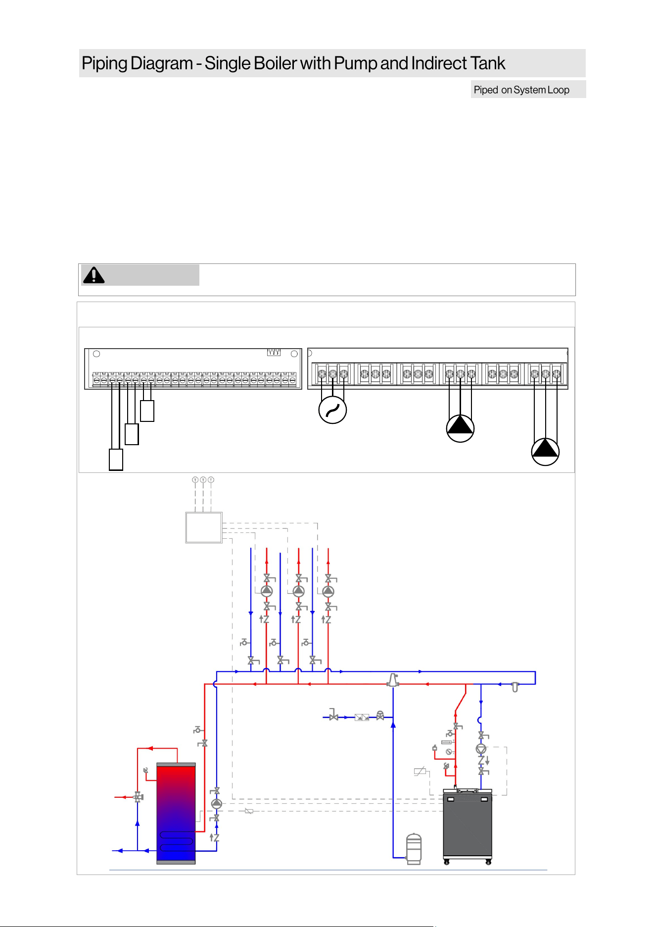
66 Rinnai Commercial Boiler Installation and Operation Manual
MAIN POWER
BOILER PUMP
DHW PUMP
POWER INPUT AUX 1 AUX 2 QX1 QX2 QX3
L N G L N G L N G L N G L N G L N G
BX1 B3-8 B9 H5 H4 H3 BX2 PWM UX2 UX3 H6-1 H6-2 H6-3
OUTDOOR SENSOR
ROOM THERMOSTAT 1
+ - + - + - + -
LOW VOLTAGE CONNECTION
HIGH VOLTAGE CONNECTION
DHW SENSOR/AQUASTAT
NOTES:
• Primary/Secondary piping must be used (closely spaced tees or low loss header).
• All closely spaced tees shall be within 4 pipe diameters center to center spacing.
• The minimum boiler piping must be at least 1-1/2 inch for RCB500AN model and 2 Inch for
RCB750AN and RCB1000AN models. Do not downsize boiler heang loop.
• It is recommended to use a check valve to prevent reverse ow and/or gravity circulaon when
pump is in o-cycle.
• Boiler pump must be properly sized to ensure proper ow rate through the boiler and related
piping (minimum ow rate must be maintained to prevent short cycling)
• Indirect Water Heater Applicaon—Ensure boiler output does not exceed indirect water heater
transfer capability.
• System ow rate should always be greater than boiler primary loop ow rate when the boiler is in
operaon to prevent short cycling.
WARNING
Low temperature heang zones must be protected with a mixing valve if
running simultaneous DHW and Central Heang.
This is not an engineering drawing; it is
intended only as a guide and not as a
replacement for professional engineering
project drawings. This drawing is not intended
to describe a complete system. It is up to the
contractor or engineer to determine the
necessary components and conguraon of the
parcular system to be installed. The drawing
does not imply compliance with local building
code requirements. It is the responsibility of the
contractor or engineer to ensure the
installaon is in accordance with all local
building codes. Confer with local building
ocials before installaon.
Figure 51
ZONE
CONTROL
PANEL
OUTDOOR
SENSOR
ROOM
THERMOSTAT-1
BOILER
PUMP
DHW
PUMP
DHW SENSOR /
AQUASTAT
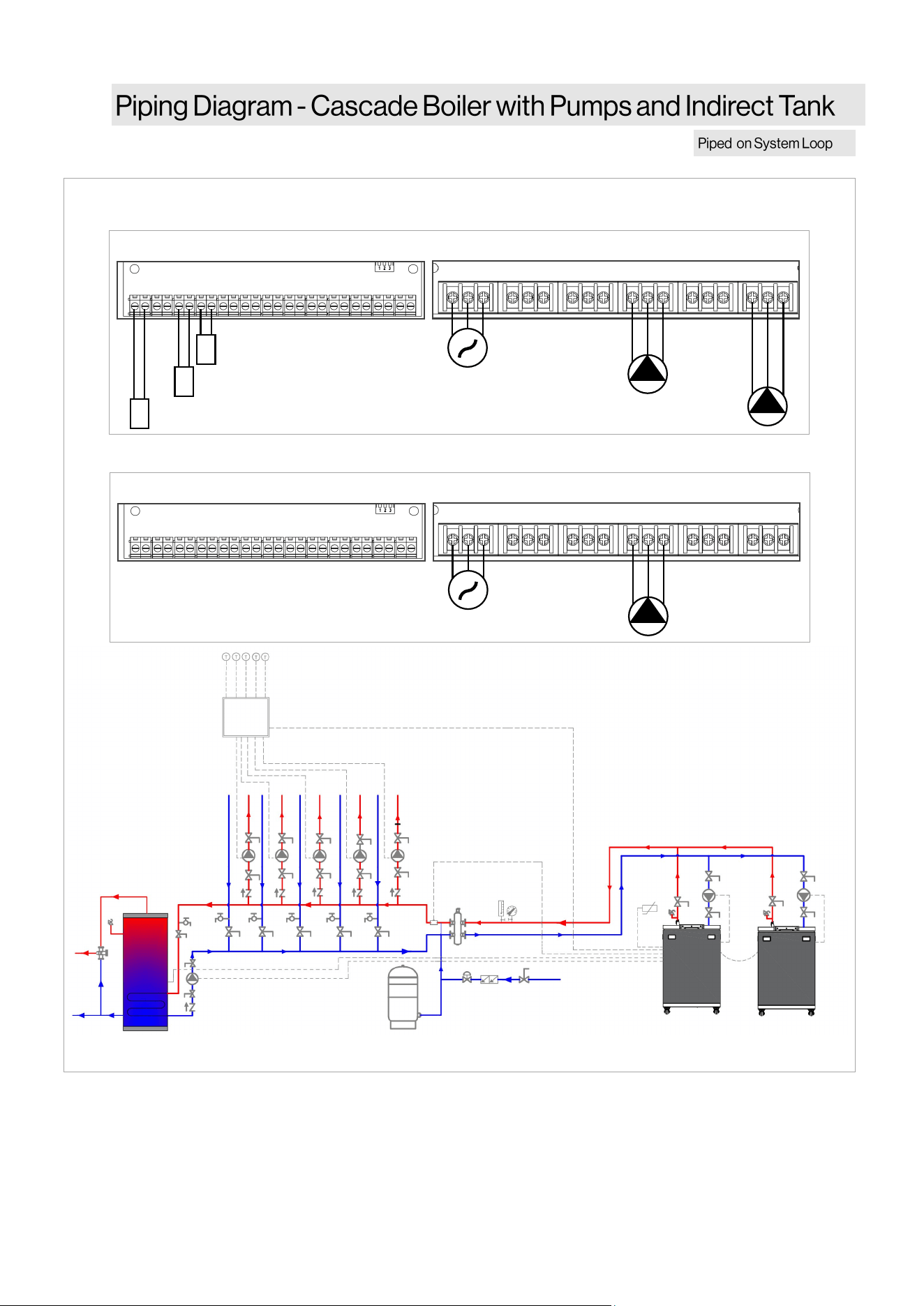
Rinnai Commercial Boiler Installation and Operation Manual 67
This is not an engineering drawing; it is intended only as a guide and not as a replacement for
professional engineering project drawings. This drawing is not intended to describe a complete
system. It is up to the contractor or engineer to determine the necessary components and
conguraon of the parcular system to be installed. The drawing does not imply compliance with
local building code requirements. It is the responsibility of the contractor or engineer to ensure the
installaon is in accordance with all local building codes. Confer with local building ocials before
installaon.
MAIN POWER
BOILER PUMP
DHW PUMP
POWER INPUT AUX 1 AUX 2 QX1 QX2 QX3
L N G L N G L N G L N G L N G L N G
BX1 B3-8 B9 H5 H4 H3 BX2 PWM UX2 UX3 H6-1 H6-2 H6-3
OUTDOOR SENSOR
ROOM THERMOSTAT 1
+ - + - + - + -
LOW VOLTAGE CONNECTION
HIGH VOLTAGE CONNECTION
CASCADE SYSTEM SENSOR
MAIN POWER
BOILER PUMP
POWER INPUT AUX 1 AUX 2 QX1 QX2 QX3
L N G L N G L N G L N G L N G L N G
BX1 B3-8 B9 H5 H4 H3 BX2 PWM UX2 UX3 H6-1 H6-2 H6-3
+ - + - + - + -
LOW VOLTAGE CONNECTION
HIGH VOLTAGE CONNECTION
MASTER UNIT
FOLLOWER UNIT
ZONE
CONTROL
PANEL
OUTDOOR
SENSOR
ROOM
THERMOSTAT-1
BOILER
PUMP
DHW SENSOR / AQUASTAT
DHW
PUMP
BOILER
PUMP
CASCADE SYSTEM SENSOR
Figure 52

68 Rinnai Commercial Boiler Installation and Operation Manual
NOTES:
• Primary/Secondary piping must be used (closely spaced tees or low loss header).
• All closely spaced tees shall be within 4 pipe diameters center to center spacing.
• The minimum boiler piping must be at least 1-1/4 inch. Do not downsize boiler heang loop.
• It is recommended to use a check valve to prevent reverse ow and/or gravity circulaon when
pump is in o-cycle.
• Boiler pump must be properly sized to ensure proper ow rate through the boiler and related
piping (minimum ow rate must be maintained to prevent short cycling)
• Indirect Water Heater Applicaon - Ensure boiler output does not exceed indirect water heater
transfer capability.
• System ow rate should always be greater than boiler primary loop ow rate when the boiler is
in operaon to prevent short cycling.
Rinnai Commercial Boiler Installation and Operation Manual 69
IMPORTANT
• Do not use an extension cord or
adapter plug with the boiler.
• If an external electrical source is
ulized, the boiler, when installed,
must be electrically bonded to
ground in accordance with the
requirements of the authority having
jurisdicon or, in the absence of
such requirements, with the
Naonal Electrical Code, ANSI/NFPA
70, and/or the Canadian Electrical
Code Part I, CSA C22.1, Electrical
Code.
When connecng the power supply, follow
these guidelines:
• Connect 120 VAC power wiring to the line
voltage power terminals.
• The boiler requires 120 VAC, 60 Hz power
from a properly grounded circuit.
• A 20 amp (recommended) fused disconnect
or service switch must be installed as
required by the code.
• Do not rely on the gas or water piping to
ground the boiler. Ground locaons are
provided inside the boiler.
• The wiring diagram is located on the inside
of the boiler front cover.
To avoid possible electrical shock hazard,
turn o electrical power supply to the
boiler before:
• Performing repairs or installaon to
internal components or accessories.
• Making wiring connecons and/or
changes to the wiring terminals on
the boiler.
• No changes may be made to the wiring of
the boiler.
• All connecons should be designed in
accordance with the applicable
regulaons.
• Label all wires prior to disconnecon
when servicing controls. Wiring errors can
cause improper and dangerous operaon.
• Verify proper operaon aer servicing.
A manually-operated remote switch should
be located outside the boiler room door for
shung down the boiler. Consideraon
should be given to protect the switch
against tampering. If there is more than one
door to the boiler room, a switch should be
located at each door.
Topics in this secon
• Guidelines
• Electrical Connecons
• Post-Power Supply Connecon
Checklist
WARNING
CAUTION
CAUTION
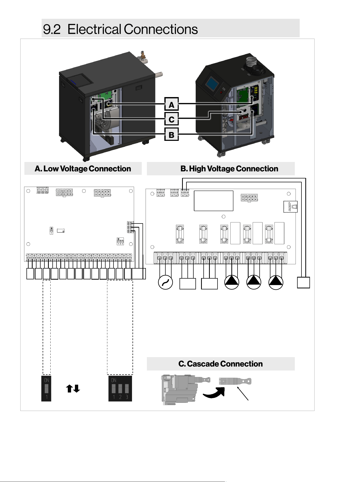
70 Rinnai Commercial Boiler Installation and Operation Manual
24VDC POWER OUTPUT
View of electrical connecons with boiler side panel removed.
Figure 53
+ - + - + - + -
BX1 B3-8 B9 H5 H4 H3 BX2 PWM UX2 UX3 H6-1 H6-2 H6-3
CASCADE SYSTEM SENSOR
DHW SENSOR/AQUASTAT
OUTDOOR SENSOR
ROOM THERMOSTAT 1
ROOM THERMOSTAT 2
0-10 VDC INPUT
OPTIONAL SENSOR
PWM MODULATING PUMP
ANALOG OUTPUT
ANALOG OUTPUT
HIGH/LOW GAS PRESSURE SWITCH
WATER TEMPERATURE HIGH LIMIT
LWCO
BMS
A+ B– G
A+ B– REF
+ - + - + - + - A+ B- G
ON (closed)
OFF (open)
+ - + - + - + -
Cascade Communicaon Connecon
1. When connecng an outdoor sensor, ensure to move the DIP switch to the OFF posion. The board is
supplied with a built-in resistor to provide a false outside temperature in order to eliminate an error code
on the screen.
2. When connecng a safety input to terminals H6, ensure to move the DIP switch to OFF posion. These DIP
switches also can be sued to trouble shoot which safety input is causing the error code.
BMS
WSC
MAIN POWER
INTERNAL FAN
AUXILIARY POWER
BOILER PUMP
CH PUMP
DHW PUMP
POWER INPUT AUX 1 AUX 2 QX1 QX2 QX3
L N G L N G L N G L N G L N G L N G
5A 5A 5A 5A 5A
24+ 24-
A+ B-
WS COMM
24+ 24
-
24DC OUT
24+ 24
-
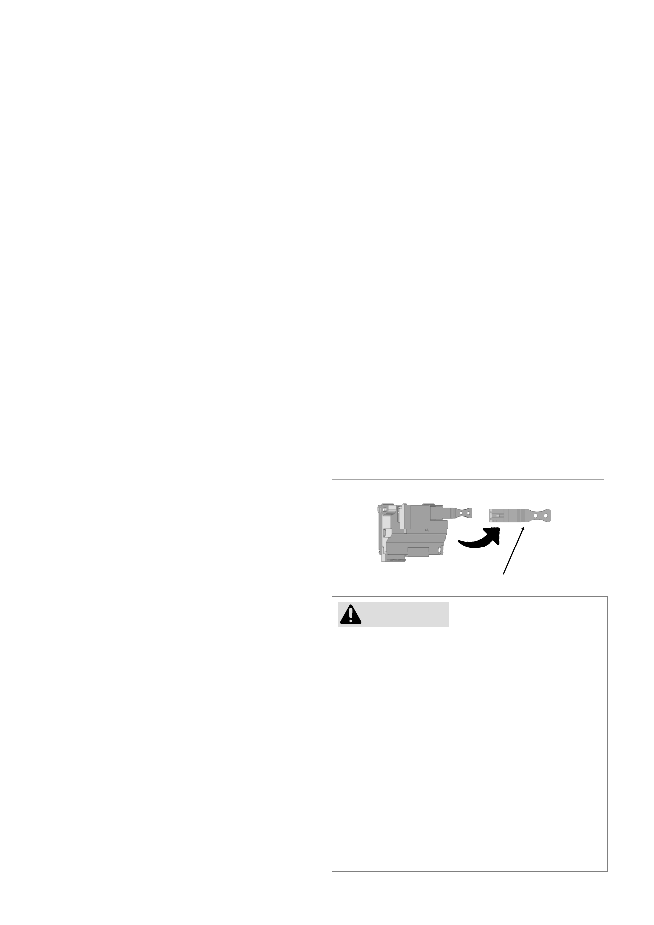
Rinnai Commercial Boiler Installation and Operation Manual 71
• PWM Modulang Pump
Not used (PWM)
• UX2 / UX3 Analog Output (0-10V)
This connecon is used to provide 0-10V signal
for boiler modulaon. U2; U3.
• Safety Inputs
Use terminals H6-1, H6-2, and H6-3 to connect
external safety devices (Gas Pressure Switches,
Water Temperature High Limit, and LWCO).
NOTE: These terminals are jumped from the
factory with DIP switches (On posion). Ensure
to set the DIP switches to OFF posion when
connecng external devices.
• Modbus / BACnet
Connect the Modbus / BACnet interface
module to the low voltage terminal BMS.
• Cascade Connecon
Connect boilers with each other by using a pair
of 22 gauge wires connected to the cascade
modules located next to the low voltage
terminals. When more than 2 units are
connected, the units located between 2 or
more boilers will take 2 sets of wires to create
a daisy-chain connecon.
• Rinnai recommends the use of spade connectors or
similar components for wiring to the screw
terminals.
• Ensure that the insulaon of the wire is not exposed
to contact any other components besides the
terminal.
• If exposed wiring contacts to any other exposed
wiring or metal components, an electrical short may
occur and cause damage to the PCB or other
connected components.
• Use proper size of screwdriver for prevenng the
screw on the terminal from breaking.
• Do not use an electric or torque screwdriver for
wiring on the PC Board.
• Wiring should pass through the grommets provided
at the boom of the boiler.
• Use the proper diameter and size of wiring.
CAUTION
Low Voltage Connecons (Signal Terminals):
• Cascade Sensor (system supply sensor)
Connect the cascade system sensor to
the low voltage terminal BX1. On a
mulple unit installaon a system sensor
must be used and mounted to the supply
pipe of the system loop.
• DHW Sensor / thermostat
Connect the Indirect tank sensor or
thermostat (aqua stat) to the low voltage
terminal B3-8. The control is set at the
factory (default seng) to use a tank
sensor. In order to use an thermostat
please refer to control secon on how to
set parameters accordingly.
• Outdoor Temperature Sensor
Connect the outdoor sensor to the low
voltage terminal B9. When an outdoor
sensor is connected, the boiler will
operate using the outdoor reset curve.
The control provides opons to set two
separate outdoor reset curves for each
room thermostat connecon. If xed
temperature operaon is desired, do not
install outdoor sensor. NOTE: This
connecon is set from the factory with a
xed temperature. Ensure to set the DIP
switch to OFF posion when using an
outdoor sensor.
• Room Thermostat
Connect the room thermostats to the low
voltage terminal H5 and H4, for room
thermostat 1 and 2, respecvely. The
room thermostat 1 is enabled from the
factory. The room thermostat 2 is
disabled from the factory, in order to use
this connecon, a parameter will need to
be enabled in the control (refer to the
control secon). NOTE: Room thermostat
2 cannot be used if an Indirect Tank is
connected to the boiler.
• Boiler Management System (0-10V
Input)
Connect the BMS to the low voltage
terminal H3. An external control may be
used to control the setpoint of the boiler.
NOTE: This control does not take priority
over a room thermostat.
• Oponal Sensor
Not used (BX2)
Figure 54
Cascade Communicaon Connecon
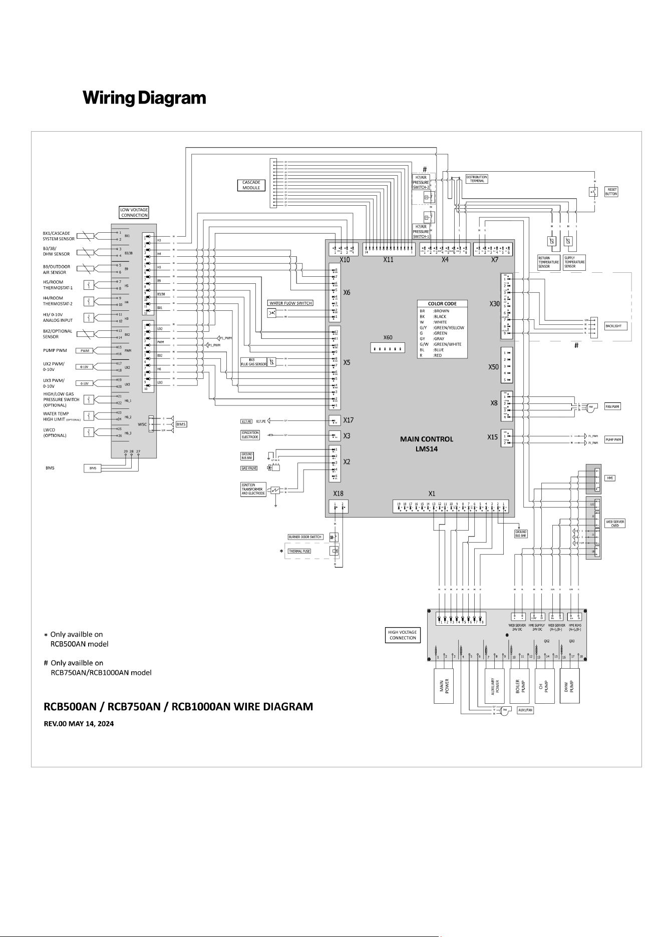
72 Rinnai Commercial Boiler Installation and Operation Manual
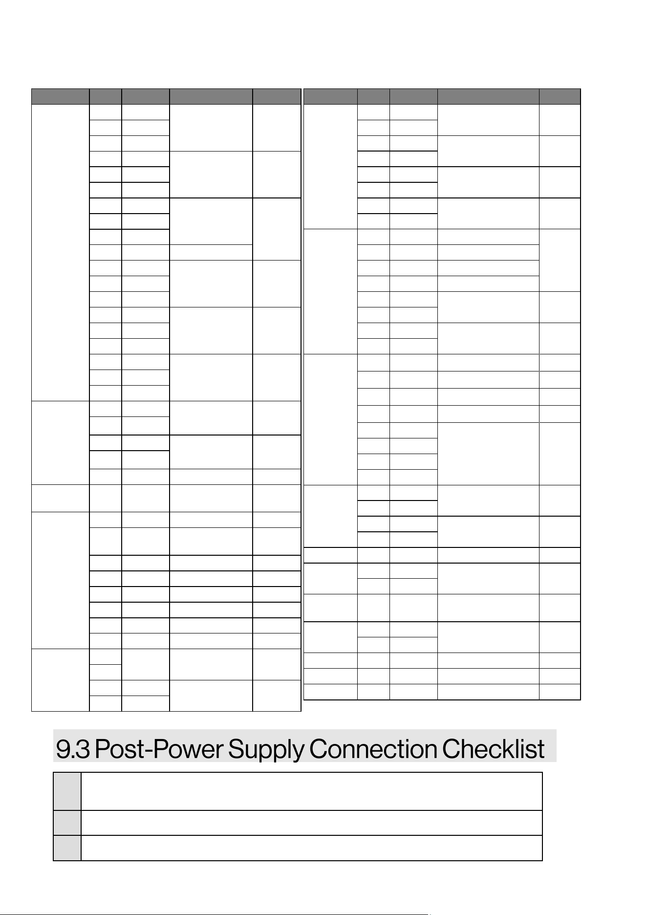
Rinnai Commercial Boiler Installation and Operation Manual 73
□
Conrm that the electricity is supplied from a 120 VAC, 60 Hz power source and is in a
properly grounded circuit.
□
Conrm that an extension cord or adapter plug has NOT been used with the boiler.
□
Conrm connecon terminals are connected correctly.
Connector Pin Marking Descripon Voltage
X1
1 N
Main Power
Supply
120VAC
2 PE
3 L
4 L
QX2 / CH Pump 120V AC 5 PE
6 N
7 L1/NO
QX3 / DHW
PUMP
120V AC
8 PE
9 N
10 L1/NC Not Used
11 L
QX1 / Boiler
Pump
120V AC 12 PE
13 N
14 L
AUX2 / Auxiliary
Power
120V AC 15 PE
16 N
17 L
Fan Power 120V AC 18 P
19 N
X2
1 L Gas Valve
Power
120V AC
2 N
3 L Spark
Generator
120V AC
4 N
5 Ion Not used -
X3 - Ion
Ionizaon
Current
-
X4
1 +15V Not used -
2 H7
Air Pressure
Switch
-
3 H3 0-10V Input -
4 RESET Reset -
5 +5V Not Used -
6 BX4/B7 Return Sensor -
7 GND Ground -
8 B2 Supply Sensor -
X5...
1
External Safety
Input
- H6
2
3 -
BX1 / Cascade
Sensor
-
4 GND
Connector Pin Marking Descripon Voltage
...X5
5 -
BX2 / Oponal Sensor -
6 GND
7 -
BX3 / Flue Gas Sensor -
8 GND
9 -
B3 /38 / DHW Sensor -
10 GND
11 -
B9 / Outdoor Sensor -
12 GND
X6
1 - H1 / Pressure Sensor
-
2 GND H1 / Pressure Sensor
3 +15V Not Used
4 +5V H1 / Pressure Sensor
5 -
H5 / Room
Thermostat 1
-
6 GND
7 -
H4 / Room
Thermostat 2
-
8 GND
X7
1
CL+ BSB
-
2
CL- BSB
-
3
G+ Not used
-
4-6
- Not used
-
X8
1 GND
Fan PWM -
2 +24
3 HALL
4 PWM
X10
1 -
UX2 - PWM / 0-10V -
2 GND
3 -
UX3 - PWM / 0-10V -
4 GND
X11 1-14 - Cascade Module -
X15
1 GND
PUMP PWM -
2 PWM
X17 - PE Ionizaon Ground -
X18
1 -
Internal Safety Input 120V AC
2 -
X30 1-9 - LED Backlight
X50 1-5 - Not Used -
X60 1-6 - Not Used -
Table 30: Connectors
74 Rinnai Commercial Boiler Installation and Operation Manual
Failure to properly commission the boiler as
described in this secon may result in
unreliable and unsafe burner operaon and
reduced component life.
THIS SECTION IS INTENDED
FOR THE INSTALLER
This boiler must be commissioned by a
licensed professional. Installer qualicaons:
A trained and qualied professional must
install the appliance, inspect it, and leak test
the boiler before use. The warranty will be
voided due to any improper installaon. The
trained and qualied professional should
have skills such as: Gas sizing; Connecng
gas lines, water lines, valves, and electricity;
Knowledge of applicable naonal, state, and
local codes; Installing venng through a wall
or roof; and training in installaon of
condensing boilers.
Boiler commissioning is a procedure used
aer boiler installaon to ensure the system
and boiler were installed correctly and ready
for operaon.
1. Ensure all boiler components are installed
correctly.
2. Open the air vent inside the boiler.
3. Power on the boiler.
4. Open the ll valve on the lling circuit.
5. Check the pressure on the pressure gauge.
Fill the boiler to a minimum of 14.5 PSI (100
kPa) water pressure and a maximum of 70
PSI (483 kPa).
6. Check the heang system for leaks.
7. Begin the deaeraon process shown in the
next secon (“10.3 Deaeraon Process”).
• Work on the boiler must be carried out
by a licensed professional, using
correctly calibrated instruments with
current test cercaon. The
commissioning instrucons are
intended for licensed professionals who
have the necessary knowledge and are
approved for working on heang and
gas systems.
• The fan will operate when power is
inially provided to perform a safety
check on the boiler.
• The boiler and its individual shut o
valve must be disconnected from the
gas supply piping system during any
pressure tesng of that system at test
pressures in excess of 1/2 PSI (3.5 kPa).
• Before the boiler is red for the rst
me:
− Ensure the boiler and system are
fully de-aerated
− Purge the gas line between the gas
meter and boiler
− Prime the pump (as described in
this secon)
IMPORTANT
IMPORTANT
Topics in this secon
• Safety Precauons
• Filling Process
• Deaeraon Process
Do not ll the boiler unless permanent
power is available. Freeze protecon is not
available if the boiler is not lled, air
purged, and supplied with power and gas.
WARNING
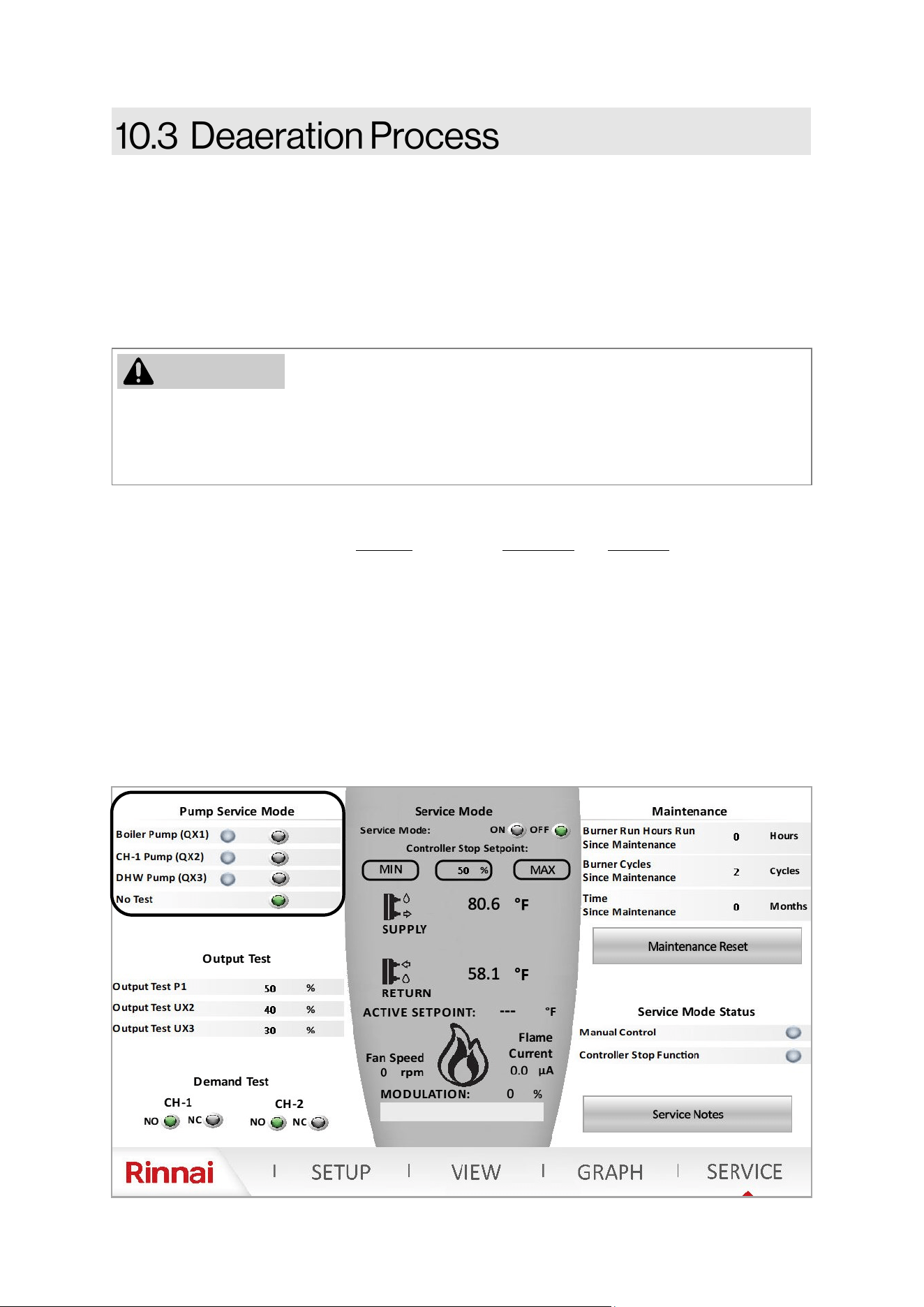
Rinnai Commercial Boiler Installation and Operation Manual 75
DO NOT operate the boiler without performing deaeraon process. Perform deaeraon during
commissioning or if any part of the system has been opened or disconnected. Failure to properly
deaerate the boiler and system may result in damage to the boiler, which is not covered by the
boiler warranty.
Deaeraon is an eecve method of purging air from the boiler aer the system has been lled or
serviced.
1. Fill the boiler to a minimum of 14.5 PSI (100 kPa) water pressure and a maximum of 70 PSI (483
kPa).
2. The deaeraon process should be performed for at least 15 minutes if all three (3) pumps
terminals are being used.
3. Aer approximately one week, all air in the system should be eliminated via the air separator in
the piping system.
Press the SERVICE icon on the boiler home page. It will prompt the user to enter a password. In
order to access the SERVICE page, the control will prompt the user to select the access level and
enter password. The password for Installer is 9419. The technician and Engineer user levels can
ONLY be accessed by a Rinnai employee.
Use the Pump Service Mode to manually energize each pump individually to remove air from the
system. It is recommended to run each pump for a minimum of ve (5) minutes in order to purge
the air from the system. Run the Boiler Pump to remove air from the primary boiler circuit. If and
indirect tank is being used, also run the DHW Pump to remove air from the DHW piping. Then move
to each central heang zones to remove air from the system side (Run CH-1 Pump and/or DHW
Pump (If assigned for a CH-2 zone).
NOTE: It is crical that the Pump Service Mode is set to No Test when the deaeraon service has
been completed.
WARNING
76 Rinnai Commercial Boiler Installation and Operation Manual
Complete the following checklist when boiler installaon is complete. You should be able to answer
YES to each queson. If you answer NO, installaon is not complete. Refer to the applicable secon
in this manual for addional informaon.
INSTALLATION LOCATION YES NO
Have you veried the unit, vent and air intakes meet the clearance requirements?
VENTING YES NO
Have all corrosive compounds been removed from around the combuson air intake of
the boiler?
Have you followed the combuson air requirements to provide sucient combuson air
for the boiler?
Are the correct venng products for the installed model being ulized?
Have you installed the vent screen(s) for Schedule 40 PVC/CPVC vent applicaons if
applicable?
Have you veried the vent system does not exceed maximum length?
SYSTEM PIPING YES NO
Have the water lines been purged of all debris and the lter cleaned?
Have you veried the supply and return water lines to the boiler are not interchanged?
Does the water supply to the boiler have adequate pressure? Is it free of chemicals? Did
you verify it does not exceed total hardness that will damage the heat exchanger?
Have you veried that no toxic chemicals were introduced to the potable water?
Did you drain the boiler if not intended to be used immediately?
Have water quality issues (if any) been addressed?
Have you performed the leak and pressure test for the boiler and plumbing system?
CONDENSATE DRAIN YES NO
Did you verify the condensate drain pipe is as short as possible and has a downward
pitch toward the drain or condensate pump?
Is all condensate drained and disposed of as per local codes?
Did you use ONLY corrosion resistant materials for the condensate drain lines?
Did you verify the condensate drain pipe along its enre length is at least the same
diameter as the drain line?
Did you check to ensure the condensaon drain lines are protected from freezing?
Have you veried the condensate drain line is not plumbed with the pressure relief
valve?
Have you conrmed the condensate drain line is not connected with an air condioning
evaporator coil drain?
This boiler has an integrated condensate trap. Have you veried that an external
condensate trap is not installed?
Have you conrmed the end of the condensate drain pipe is open to atmosphere?
Has an air gap been installed in the condensate drain line?
Table: Post-Installaon Checklist
Rinnai Commercial Boiler Installation and Operation Manual 77
GAS SUPPLY YES NO
Did you verify the gas system is appropriately sized?
Did you verify the boiler is rated for the gas type supplied?
Have you performed a gas line and connection leak test?
Did you install a manual gas control valve in the gas line to the boiler?
Is the inlet gas pressure within limits?
Did you purge the gas line of any debris before connecting the boiler?
PRESSURE RELIEF VALVE (PRV)
YES NO
Does the PRV comply with the standard for Relief Valves and Automatic Gas Shutoff De-
vices for Hot Water Supply Systems ANSI Z21.22, and/or the standard Temperature, Pres-
sure, Temperature and Pressure Relief Valves and Vacuum Relief Valves, CAN1-4.4?
Did you verify the heating system PRV is rated to 75 PSI?
Is the discharge from the PRV piped to the ground or into a drain system as per local
codes?
Is the discharge line from the PRV installed downward and does it terminate 6 in. (152
mm) above the drains?
Is the discharge end of the line plain (unthreaded) and a minimum of 3/4 in. diameter?
Is the discharge line material suitable for at least 180° F water?
Did you take measures to protect the PRV and PRV discharge line from freezing?
Have you verified the PRV is not plumbed with the condensate drain line?
Have you verified the PRV is not plugged and that reducing fittings, valves, or other re-
strictions are not installed in the relief line?
POWER SUPPLY
YES NO
Did you confirm that the electricity is supplied from 120 VAC, 60 Hz power source and is
in a properly grounded circuit?
Did you confirm that an extension cord or an adapter plug has NOT been used with the
boiler?
COMMISSIONING
YES NO
Was the boiler filled to 14.5 - 70 PSI?
Was the deaeration process performed on the boiler?
Post-Installation Checklist (Continued)
78 Rinnai Commercial Boiler Installation and Operation Manual
IMPORTANT
• On inial startup of the system, it is necessary to manually run the pumps from the service
page to remove all air from the system piping and boiler. Failure to properly deaerate the
boiler and system may result in damage to the boiler, which is not covered by the boiler
warranty.
• It can take up to a week before all the air has disappeared from a newly-lled and
pressurized installaon. During the rst week of operaon, noises can be heard which
indicate the presence of air. The automac air vent in the boiler and air separator in the
heang system will remove the air, which means the water pressure will reduce some
during this period; therefore, addional water is necessary to maintain proper pressure in
the heang system. Water pressure needed for operaon:
− The boiler is in normal operaon between 14.5 - 70 PSI (100 - 483 kPa).
− The maximum pressure permied inside the heat exchanger is 160 PSI (1103 kPa).
− The pressure relief valve supplied with the boiler is rated to 75 PSI (517 kPa).
Topics in this secon
• Start-Up Informaon
• Control Panel
• Error and Diagnosc Codes
• Perform Combuson Analysis
• Operang Informaon
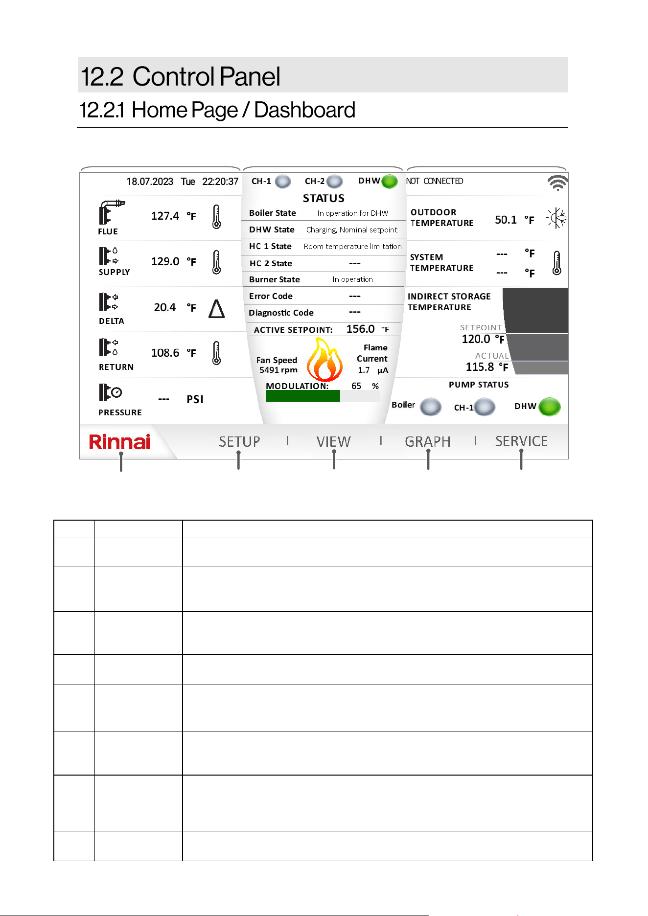
Rinnai Commercial Boiler Installation and Operation Manual 79
ITEM DESCRIPTION FUNCTION
1 RINNAI
The Rinnai logo will return the user to the home page (shown). This page will
provide informaon regarding the boiler operaon.
2 SETUP
This page will allow the user to adjust and customize parameters, such as outdoor
reset curve(s), and others. NOTE: This page should only be accessed by qualied
service technician.
3 VIEW
The view screen shows the state of the appliance and its internal components
(temperature values, switches condion, water pressure, fan speed, and all other
inputs and outputs).
4 GRAPH
The graph page allows the user to monitor real me system informaon
(temperature, pressure, pump operaon, and fan speed).
5 SERVICE
This page allows for a dierent user level selecon by choosing user from the
dropdown menu and enter a password to access parameters from basic to crical
funcons.
6 LEFT PANE
This pane provides informaon about boiler internal temperature and pressure. It
also incudes date and me. NOTE: Date and me can be changed from the setup
page.
7 CENTER PANE
This pane shows informaon about demand, boiler modulaon, error messages,
setpoint, fan speed, and ionizaon current. The center pane changes color to show
the boiler status: Dark Gray - standby; Light Gray - Running; Red - Error Code (hard
lockout), Yellow - Error Code (so lockout); Orange - service reminder
8 EXTERNAL
This pane shown informaon about external devices connect to the boiler (outdoor
sensor, system sensor, indirect tank sensor/thermostat, pump status, and Wi-Fi ).
❶
❷
❸
❹
❺
❼ ❽
Table 31: Home Screen
❻
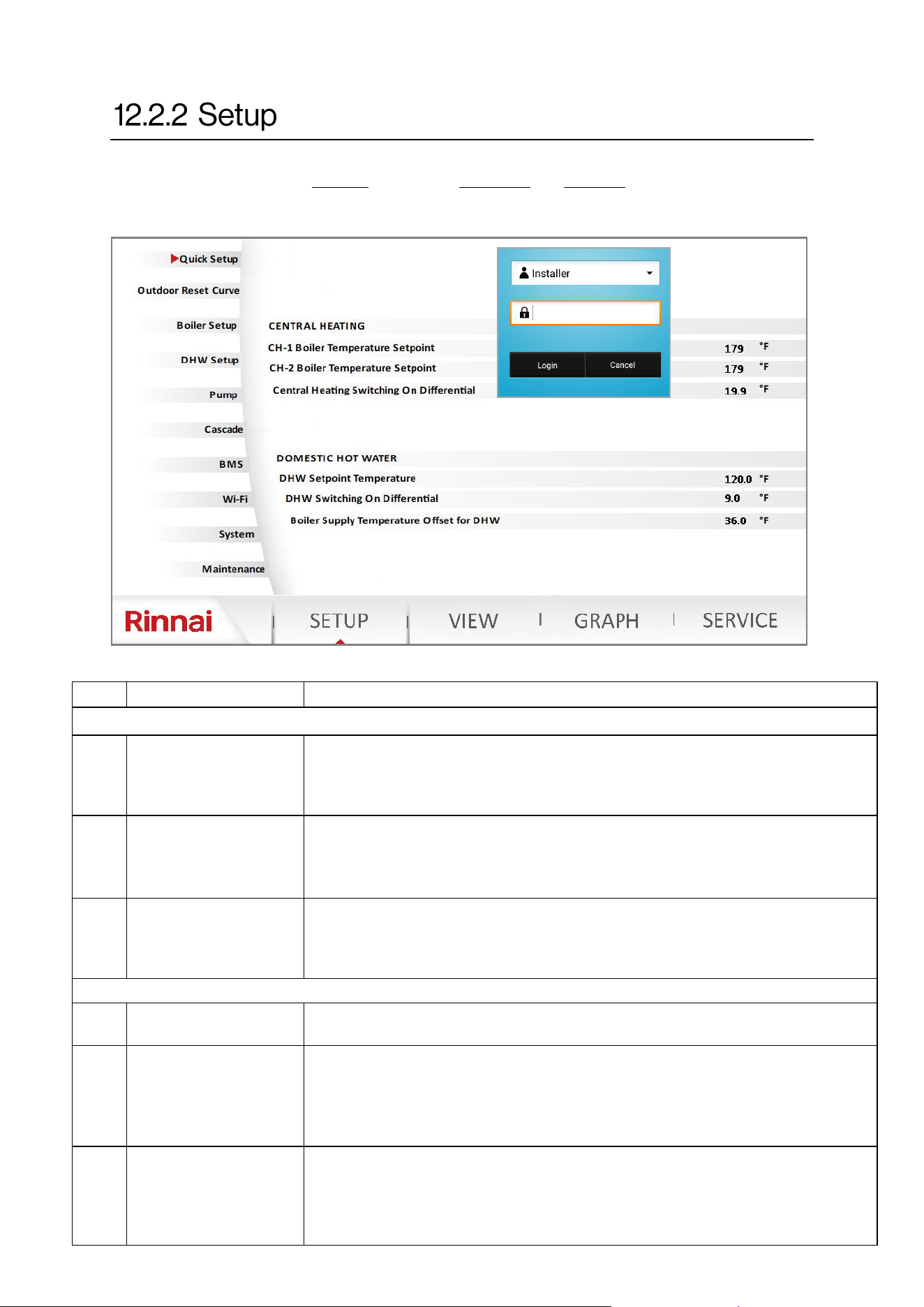
80 Rinnai Commercial Boiler Installation and Operation Manual
NO. DESCRIPTION FUNCTION
CENTRAL HEATING
1
CH-1 Boiler
Temperature Setpoint
This parameter is used to set the boiler supply temperature setpoint for CH-1
manually if an outdoor sensor is not used. When an outdoor reset funcon is
desired use the Outdoor Reset Curve page to set the boiler min and max
temperatures. Range: 86°F [30°C] - 180°F [82°C]; Default: 180°F [82°C]
2
CH-2 Boiler
Temperature Setpoint
This parameter is used to set the boiler supply temperature setpoint for CH-2
manually if an outdoor sensor is not used. When an outdoor reset funcon is
desired use the Outdoor Reset Curve page to set the boiler min and max
temperatures. Range: 86°F [30°C] - 180F [82°C]; Default: 180°F [82°C]
3
Central Heang
Switching On
Dierenal
This parameter is used to set the temperature dierenal when the boiler will
light up the burner. For instance if the boiler setpoint is 180°F [82°C] and this
parameter is set to 20°F [11°C], the boiler will ONLY re when the actual supply
temperature is below 160°F [71°C]. Range: 0°F [0°C] - 36°F [20°C]
DOMESTIC HOT WATER
4
DHW Temperature
Setpoint
This parameter is used to set the temperature setpoint for the DHW indirect tank.
Range: 104°F [40] - 176°F [80°C]; Default: 120°F [49°C]
5
DHW Switching On
Dierenal
This parameter is used when a DHW indirect tank is controlled via a sensor. This
parameter sets the temperature dierenal when the DHW tank will call for heat
demand. For instance if the Indirect tank setpoint is 120°F [49°C] and this
parameter is set to 9°F [5°C], the boiler will ONLY acvates the DHW demand
when tank temperature is below 111°F [44°C]. Range: 0°F [0°C] - 36°F [20°C]
6
Boiler Supply
Temperature Oset for
DHW
When there is a DHW demand, the boiler temperature setpoint will be the DHW
temperature setpoint + this parameter. For instance if DHW temperature setpoint
is 120°F [49°C] and this parameter is set to 36°F [20°C] the boiler supply setpoint
for DHW will be 156°F [69°C]. Range: -4°F [-20°C] - 108°F [60°F], Default: 36°F
[20°C]
Table 32: Setup Page
To access the SETUP page, the control will prompt the user to select the access level and enter
password. The password for Installer is 9419. The technician and Engineer user levels can ONLY
be accessed by a Rinnai employee.
Quick Setup
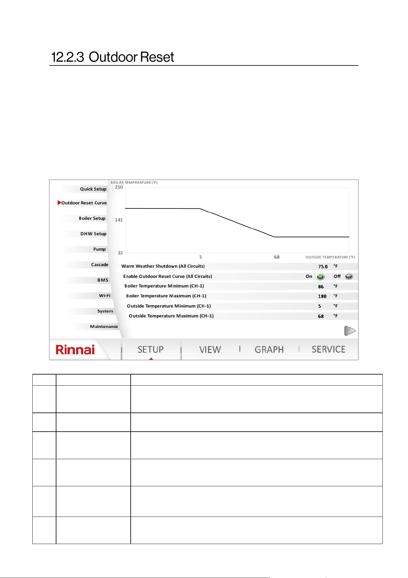
Rinnai Commercial Boiler Installation and Operation Manual 81
An outdoor sensor is provide with the boiler. The boiler control allows for two customizable
outdoor reset curves for each head demand from room thermostats one and two. The graph below
represents outdoor reset curve for heang circuit one. To set the second outdoor reset curve press
on the arrow at the boom right corner of the page. Set the minimum and maximum boiler supply
temperatures along with minimum and maximum outside temperatures to set outdoor reset
curves. The warm weather shutdown is the temperature value at which the boiler will ignore the
call for heat. Use the outdoor reset power icon to enable or disable the outdoor reset curve. When
an outdoor sensor is not being used the boiler will operate using the maximum boiler temperature
value set in this table. When the outdoor reset curve is not intended to be used, the boiler setpoint
can be set from the quick setup page and the outdoor reset curve should be disabled. See next
page for outdoor reset temperature guideline.
NO. DESCRIPTION FUNCTION
1
Warm Weather
Shutdown (All Circuits)
This parameter is used to set the outside temperature to disable boiler operaon
for central heang due to warm weather. Range: 46°F [8°C] - 86°F [30°C]; Default:
75°F [24°C]
2
Enable Outdoor Reset
Curve (All Circuits)
This parameter is used to enable or disable the outdoor reset curve funcon.
Range: On - O; Default: On
3
Boiler Temperature
Minimum (CH-1)
This parameter sets the minimum boiler supply temperature for the outdoor
reset curve. Range: 86°F [30°C] - Boiler Temperature Maximum; Default: 86°F
[30°C]
4
Boiler Temperature
Maximum (CH-1)
This parameter the sets the maximum boiler supply temperature for the outdoor
reset curve. Range: Boiler Temperature Minimum - 180°F [82°C]; Default: 180°F
[82°C]
5
Outside Temperature
Minimum (CH-1)
This parameter sets the minimum boiler outside temperature for the outdoor
reset curve. Range: -40°F [-40°C] - Outside Temperature Maximum; Default: 5°F
[-15°C]
6
Outside Temperature
Maximum (CH-1)
This parameter the sets the maximum outside temperature for the outdoor reset
curve. Range: Boiler Temperature Minimum - Warm Weather Shutdown; Default:
68°F [20°C]
Table 33
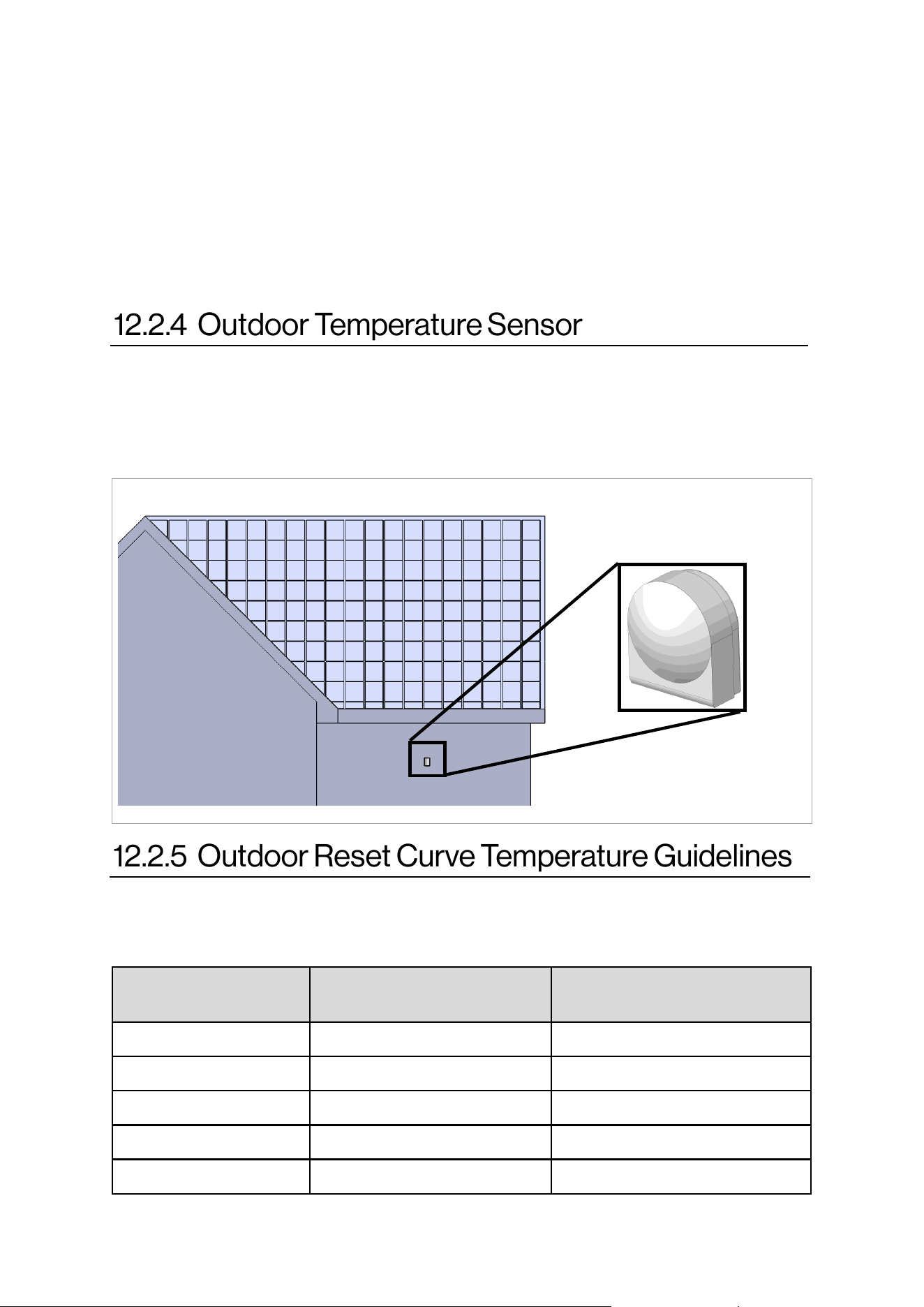
82 Rinnai Commercial Boiler Installation and Operation Manual
Outdoor reset is a built-in funcon to help maximize the eciency of the boiler. The design of this
funcon is to adjust the target temperature of the boiler relave to the outdoor ambient
temperature via the exible outdoor reset curve opons included in the boiler setup page. The
outdoor ambient temperature is observed via the provided outdoor temperature sensor.
NOTE: When a DHW indirect tank is installed as a heang zone, and the outside temperature may
exceed the maximum limit of warm weather shutdown (86°F), the outdoor reset must be disabled.
During warm weather shutdown, the boiler will not provide any heat to the indirect tank if it is
connected to the boiler as a heang zone.
The outdoor temperature sensor (1 kOhm) should be mounted to avoid direct sun light (to prevent
obtaining false reading of the outdoor temperature) ideally on a North facing wall of the house.
The sensor should also be mounted away from any vent, duct, or other device that may create an
arcial heat source. The sensor should then be wired back to the outdoor temperature sensor
terminal on the boiler. Refer to the wiring secons for more informaon.
North Facing Wall
Type of Heat Emier
Typical Minimum Supply
Temperature
Typical Maximum Supply
Temperature
Hydronic Air Handler 120 - 140°F 140 - 180°F
Unit Heater 130 - 140°F 160 - 180°F
Base Board Convectors 100 - 140°F 140 - 180°F
Cast Iron/Panel Radiator 90 - 120°F 140 - 180°F
Undermount Radiant 100 -120°F 120 - 150°F
Below are some typical target temperatures for various heat emiers. These are basic guidelines;
thus, check with the emier manufacturer or consult your heang design engineer.
Outdoor Temperature
Sensor
Figure 55
Table 34
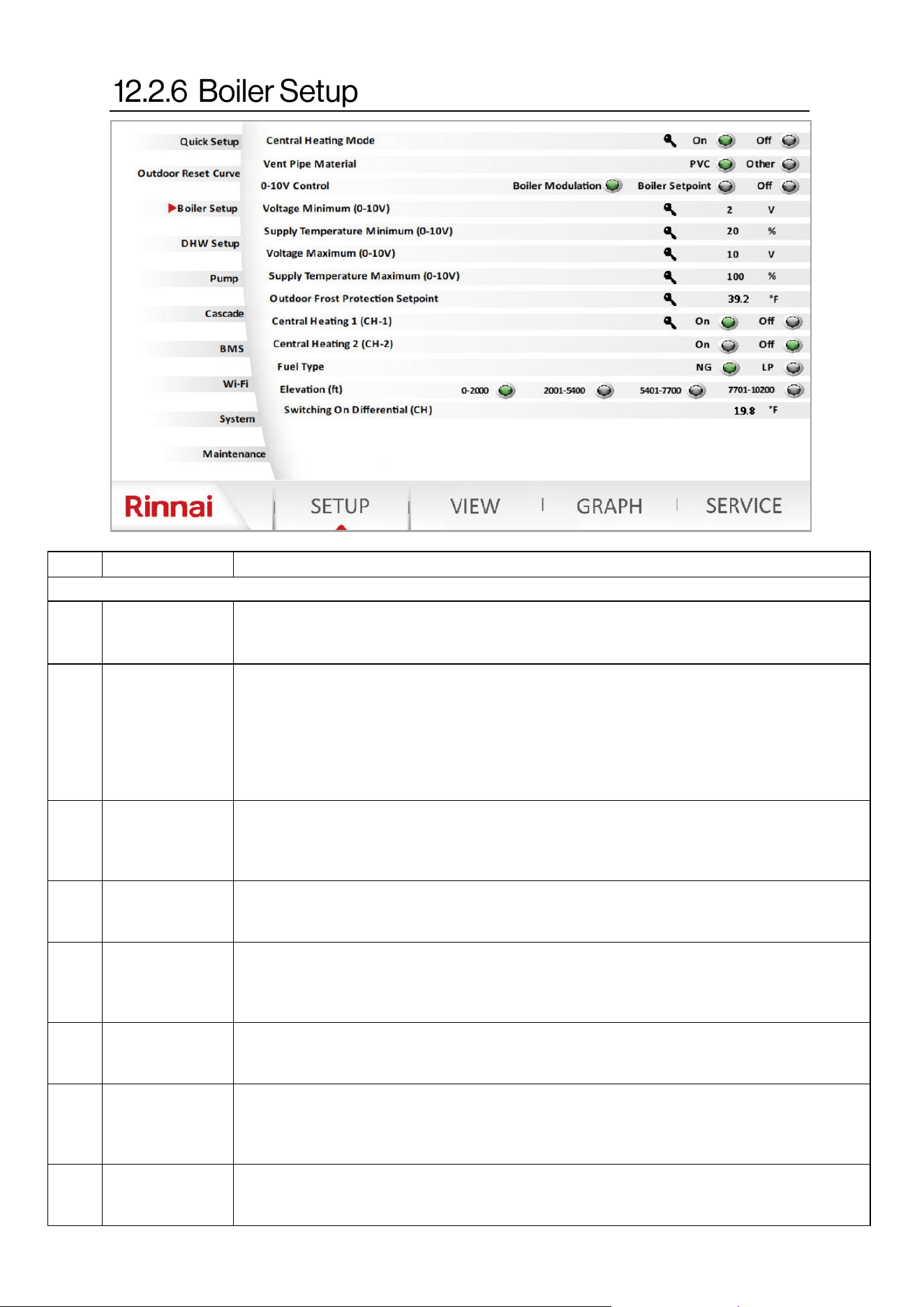
Rinnai Commercial Boiler Installation and Operation Manual 83
NO. DESCRIPTION FUNCTION
Boiler Setup
1
Central Heang
Mode
This funcon enables or disables the central heang mode (Room Thermostat 1, Room
Thermostat 2, and 0-10V input funcons). Range: On - O; Default: On NOTE: Requires
Technician or Engineer level for access.
2
Vent Pipe
Material
This parameter will set the ue temperature limit based on the material used for venng.
When set to PVC, the boiler will start to reduce modulaon when the vent temperature
reaches 140°F [60°C] and will shutdown at 149°F [65°C]. When set as others (CPVC, PP, and
FNS), the boiler will reduce modulaon when the vent temperature reaches 198°F [92°C]
and will shutdown and lockout at 207°F [97°C]. Ensure to use the proper venng material
and appropriate parameter seng depending on the applicaon to prevent damage to the
vent pipe or boiler short cycling. Range: PVC- Others. Default: PVC
3
0-10V Input
Control
This parameter is used to select the two dierent modes of 0-10V operaon or disable the
0-10V funcon. Range: Boiler Modulaon, Boiler Setpoint, O; Default: O. NOTE: It is
recommended to avoid running low voltage wires in parallel to high voltage wiring to avoid
induced voltage. False voltage signal will cause the boiler to operate when it is not needed.
4
Voltage
Minimum
(0-10V)
This parameter sets the minimum voltage for the 0-10V input funcon. Range: 0V - 10V;
Default: 2V. NOTE: DO NOT change the default seng. Requires Technician or Engineer
level for access.
5
Supply
Temperature
Minimum
(0-10V)
This parameter sets the minimum boiler supply temperature or modulaon percentage for
0-10V input operaon. For instance when the input voltage is set to 2V, the boiler supply
setpoint is 86°F [30°C]. Range: 86°F [30°C] - Supply Temperature Maximum (0-10V);
Default: 86°F [30°C]
6
Voltage
Maximum (0-10V)
This parameter sets the maximum voltage for the 0-10V input funcon. Range: 0V - 10V;
Default: 10V. NOTE: DO NOT change the default seng. Requires Technician or Engineer
level for access.
7
Supply
Temperature
Maximum (0-10V)
This parameter sets the maximum boiler supply temperature or modulaon percentage for
0-10V input operaon. For instance when the input voltage is set to 10V, the boiler supply
setpoint is 180°F [82°C]. Range: Supply Temperature Minimum (0-10V); - 180°F [82°C] -
Default: 180°F [82°C]
8
Outdoor Frost
Protecon
Setpoint
This funcon will alert the boiler about an outside freeze condion based on the set value.
The boiler will monitor the supply temperature before acvang the freeze protecon
mode. Range: 40°F [4] - 60°F [16]. NOTE: Requires Technician or Engineer level for access.
Table 35
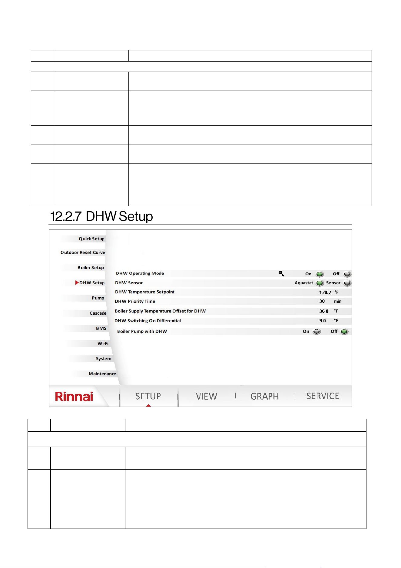
84 Rinnai Commercial Boiler Installation and Operation Manual
NO. DESCRIPTION FUNCTION
Boiler Setup (cont.)
9
Central Heang 1
(CH-1)
This parameter enables or disables CH-1 room thermostat operaon.
Range: On - O; Default: On. NOTE: Do not disable this parameter.
10
Central Heang 2
(CH-2)
This parameter enables or disables CH-2 room thermostat operaon.
Range: On - O; Default: O. NOTE: ONLY enable this parameter if you intend
to replace the DHW zone with a second CH zone. The DHW pump needs to be
assigned as CH-2 pump in the pump setup page for proper operaon.
11 Fuel Type
This funcon will assign the proper fan speed for NG or LP gas depending on the
selecon. Range: NG - LP; Default: LP
12 Elevaon
This funcon will assign the proper fan speed for each elevaon selecon.
Range: 0-2000 ; 2001-5400 ; 5401-7700 ; 7701-10200; Default: 0-2000
13
Central Heang
Switching On
Dierenal
This parameter is used to set the temperature dierenal when the boiler will
light up the burner. For instance if the boiler setpoint is 180°F [82°C] and this
parameter is set to 20°F [11°C], the boiler will ONLY re when the actual supply
temperature is below 160°F [71°C]. Range: 0°F [0°C] - 36°F [20°C] ; Default: 20°F
[11°C]
NO. DESCRIPTION FUNCTION
DHW Setup
1
DHW Operang
Mode
This funcon enables or disables DHW operaon (Aquastat or Sensor). Range:
On - O; Default: On NOTE: Requires Technician or Engineer level for access.
2 DHW Sensor
This parameter allows the user to choose either a 10K Ohm sensor (thermistor)
or an Aquastat (thermostat) to control the DHW indirect tank demand. In
Aquastat mode the control is looking for either an open (no demand) or closed
(demand) contact. In Sensor mode the control is reading the actual
temperature against the setpoint to determine heat demand. When a sensor is
accidentally selected and aquastat is used, the boiler will present an error code
when aquastat is closed. Range: Aquastat - Sensor; Default: Aquastat
Table 35 connue
Table 36
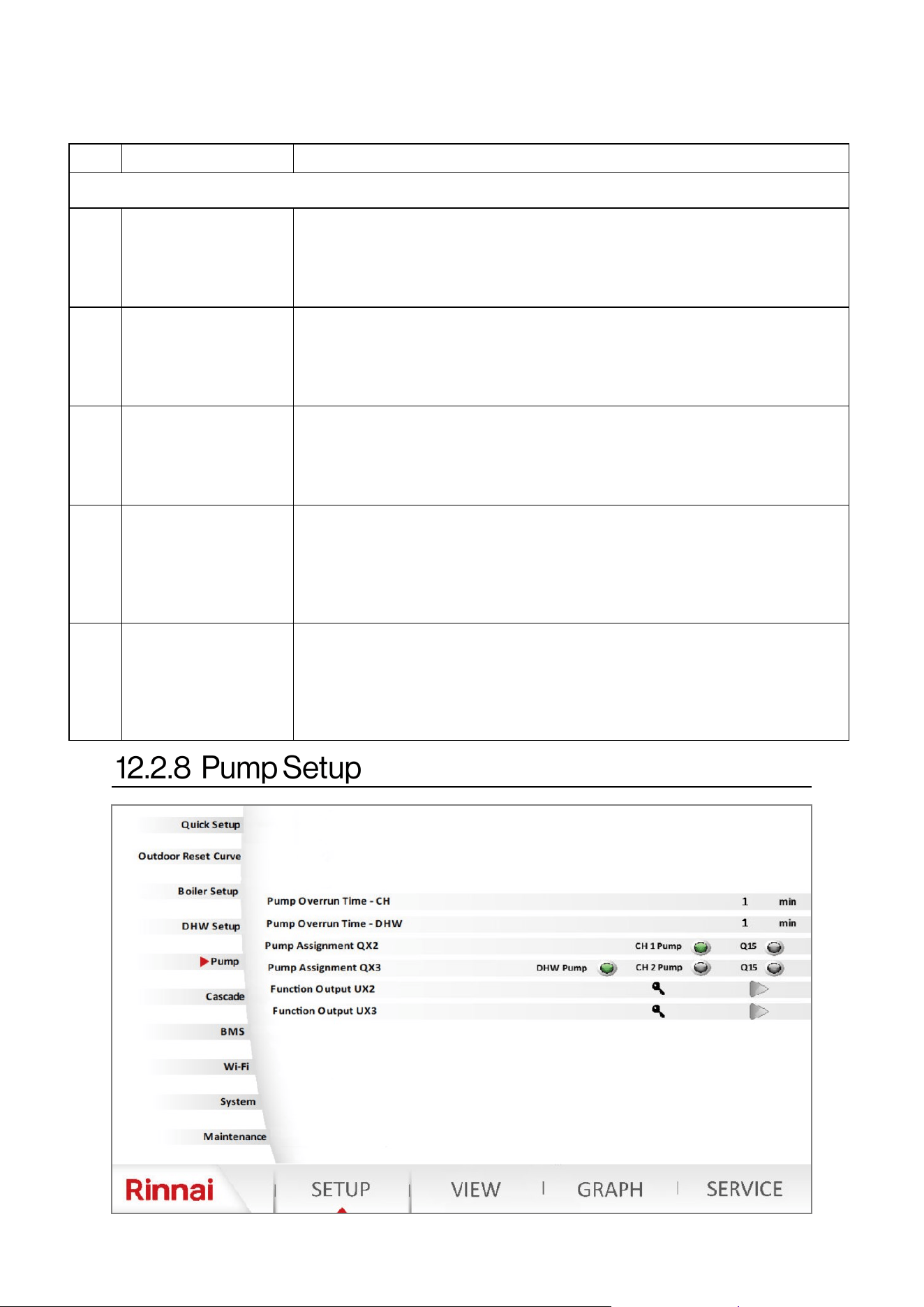
Rinnai Commercial Boiler Installation and Operation Manual 85
NO. DESCRIPTION FUNCTION
DHW Setup (cont.)
3
DHW Temperature
Setpoint
This parameter allows the user to set the DHW indirect tank temperature.
NOTE: When an aquastat is used ensure to match this parameter with the
seng on the mechanical aquastat to ensure proper operaon. The control
will use this value to set the boiler supply temperature for DHW.
Range: 104°F [40°C] - 176°F [80°C]; Default: 120°F [49°C].
4 DHW Priority Time
This parameter sets the DHW priority me in case there are both DHW and
Central Heang demands. The control will priorize DHW demand for the set
me and then switch to central heang demand. The control will switch
between the two demands unl one or both are sased.
Range: 10 - 600 Minutes; Default: 30 Minutes
5
Boiler Supply
Temperature Oset for
DHW
When there is a DHW demand, the boiler temperature setpoint will be the
DHW temperature setpoint + this parameter. For instance if DHW temperature
setpoint is 120°F [49°C] and this parameter is set to 36°F [20°C] the boiler
supply setpoint for DHW will be 156°F [69°C]. Range: -4°F [-20°C] - 108°F [60°F],
Default: 36°F [20°C]
6
DHW Switching On
Dierenal
This parameter is used when a DHW indirect tank is controlled via a sensor.
This parameter sets the temperature dierenal when the DHW tank will call
for heat demand. For instance if the Indirect tank setpoint is 120°F [49°C] and
this parameter is set to 9°F [5°C], the boiler will ONLY acvate the DHW
demand when tank temperature is below 111°F [44°C].
Range: 0°F [0°C] - 36°F [20°C]; Default: 9°F [5°C]
7 Boiler Pump with DHW
This parameter will allow the user to enable the boiler pump to operate during
a DHW demand. For instance, if the DHW indirect tank is piped in the system
loop as one of the heang zones, the boiler pump can be enabled to deliver
the heat to the system loop. NOTE: It is crical to ensure low temperature
zones are protected via mixing valve to prevent overheang due to higher
seng of boiler supply temperature for DHW. Range: On - O; Default: O
DHW Setup
Table 36 connue
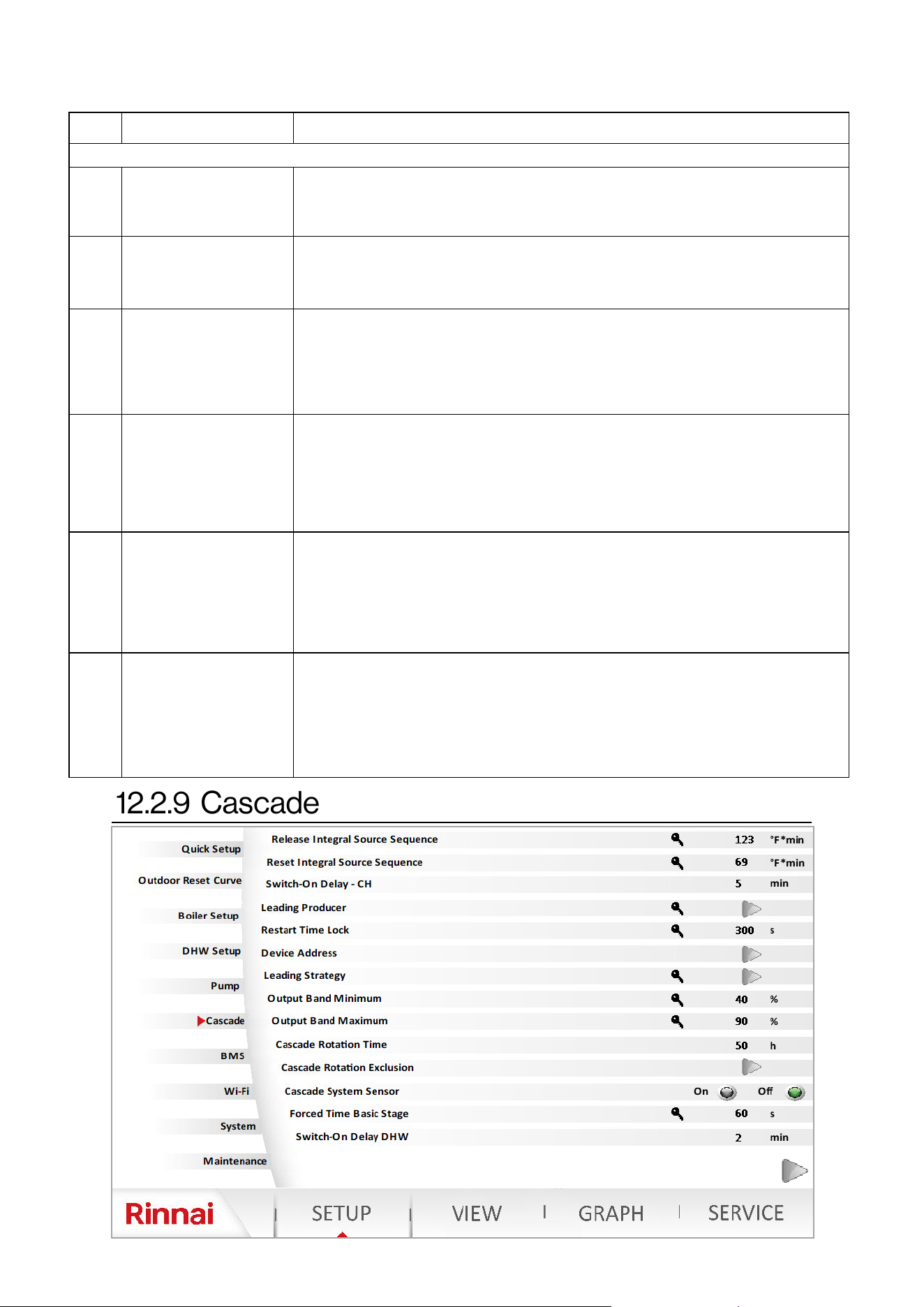
86 Rinnai Commercial Boiler Installation and Operation Manual
NO. DESCRIPTION FUNCTION
Pump Setup
1
Pump Overrun Time -
CH
Allows boiler and CH pumps to connue to run aer the ame is turned o,
when a CH demand is terminated.
Range: 0-240 Minutes; Default: 1 Minute
2
Pump Overrun Time -
DHW
Allows the DHW pump to connue to run aer the ame is turned o, when a
DHW demand is terminated.
Range: 0-240 Minutes; Default: 1 Minute
3 Pump Assignment QX2
This parameter can be used to assign the CH-1 Pump to run with a room
thermostat call (room thermostat 1) or Using a 0-10V for Boiler Temperature
control. When using Room thermostat, it should to set to CH-1 Pump, when
using 0-10V for boiler temperature control it should be set to Q15 pump.
Range: CH-1 Pump, Q15. Default: Q15
4 Pump Assignment QX3
This parameter can be used to assign the DHW pump terminal to be used as a
DHW pump , CH-2 pump, or Q15 (0-10V operang for boiler temperature
control). In case a DHW indirect tank is not used and a second heang zone is
desired, this parameter can be set to CH-2. Also CH-2 thermostat needs to be
enabled from the boiler setup page. Range: Boiler Pump; CH-1 Pump; CH-2
Pump; DHW Pump; Cascade Pump Q25; Default: DHW Pump
5 Funcon Output UX2
When Burner Modulaon is selected, this parameter can be used to read boiler
status and modulaon informaon via a 0-10V signal. 0-0.5V - Boiler in error
State; 0.5V - 1V - Boiler in O state, standby, pre-purge, post-purge...; 1V -
10V—represents 0% - 100% modulaon.
Range: None, Boiler Pump, DHW Pump, CH-1 Pump, CH-2 Pump, Burner
Modulaon; Default: Burner Modulaon.
6 Funcon Output UX3
When Burner Modulaon is selected, this parameter can be used to read boiler
status and modulaon informaon via a 0-10V signal. 0-0.5V - Boiler in error
State; 0.5V - 1V - Boiler in O state, standby, pre-purge, post-purge...; 1V -
10V—represents 0% - 100% modulaon.
Range: None, Boiler Pump, DHW Pump, CH-1 Pump, CH-2 Pump, Burner
Modulaon; Default: Burner Modulaon.
Table 37

Rinnai Commercial Boiler Installation and Operation Manual 87
NO. DESCRIPTION FUNCTION
Cascade
1
Released Integral
Source Seq
Controls the units release on a cascade system. The higher the value the
quicker is the release. Range: 0-500 C*min; Default: 51 C*min
2
Reset Integral Source
Seq
Controls when the units are shut-down in a cascade system When the value is
decreased, heat sources are switched o at a faster rate. Range: 0-500 C*min;
Default: 21 C*min
3 Switch-On Delay - CH
Sets the wait me to release units in a cascade system during a heat demand.
For instance when a unit is released for a heat demand in a cascade system
due to the modulaon load, this unit will wait for this set me before igning
the burner. Range: 0-120 Minutes; Default: 5 Minutes
4 Leading Producer
This parameters sets the rst unit that will be energized in a cascade system.
The boiler automacally follows the lead-lag strategy according to the
operang hours. Range: 1-8; Default: 1 (Master Boiler)
5 Restart Time Lock
The restart lock prevents a deacvated heat source from being switched on
again. It is released again only aer the set me elapsed. This prevents too
frequent switching acons of the heat source and ensure stable plant
operang states. Range: 0-1800 Seconds; Default: 300 Seconds
6 Device Address
This parameter sets the cascade address of the device.
Range: Standalone; Master, Follower 1, …, Follower 7. Default: Standalone
7 Leading Strategy
This parameter sets the cascade leading strategy.
Range: :Late on, early o; Late on, late o; Early on, late o.
Default: Early on, late o.
Late on, early o - Addional boilers are switched on as late as possible
(output band max) and switched o again as early as possible (output band
max). This means that the smallest possible number of boilers are in
operaon, or addional boilers operate with short on mes.
Late on, late o - Addional boilers are switched on as late as possible (output
band max) and switched o again as a late as possible (output band min). This
leads to the smallest possible number of boiler switched on/o acons for
the boiler.
Early on, late o—Addional boilers are switched on as early as possible
(output band min) and switched o again as late as possible (output band min).
This means that the largest possible number of boilers are in operaon, or
addional boilers operate with the longest possible on me.
8 Output Band Minimum
The heat sources are switched on and o according to the selected lead
strategy while giving consideraon to the preset output band.
NOTE: To deacvate the impact of the output band, the limit values must be
set to 0% and 100%, and the lead strategy to be selected is Late on, late o.
Range: 0-100%; Default: 40%
9 Output Band Maximum
The heat sources are switched on and o according to the selected lead
strategy while giving consideraon to the preset output band.
NOTE: To deacvate the impact of the output band, the limit values must be
set to 0% and 100%, and the lead strategy to be selected is Late on, late o.
Range: 0-100%; Default: 90%
10 Cascade Rotaon Time
This parameter sets the me for leading source rotaon is a cascade system.
The boiler loads in a cascaded system can be inuenced by dening the order
of a lead lag boiler.
Range: 10-990 Hours; Default: 50 Hours
Table 38
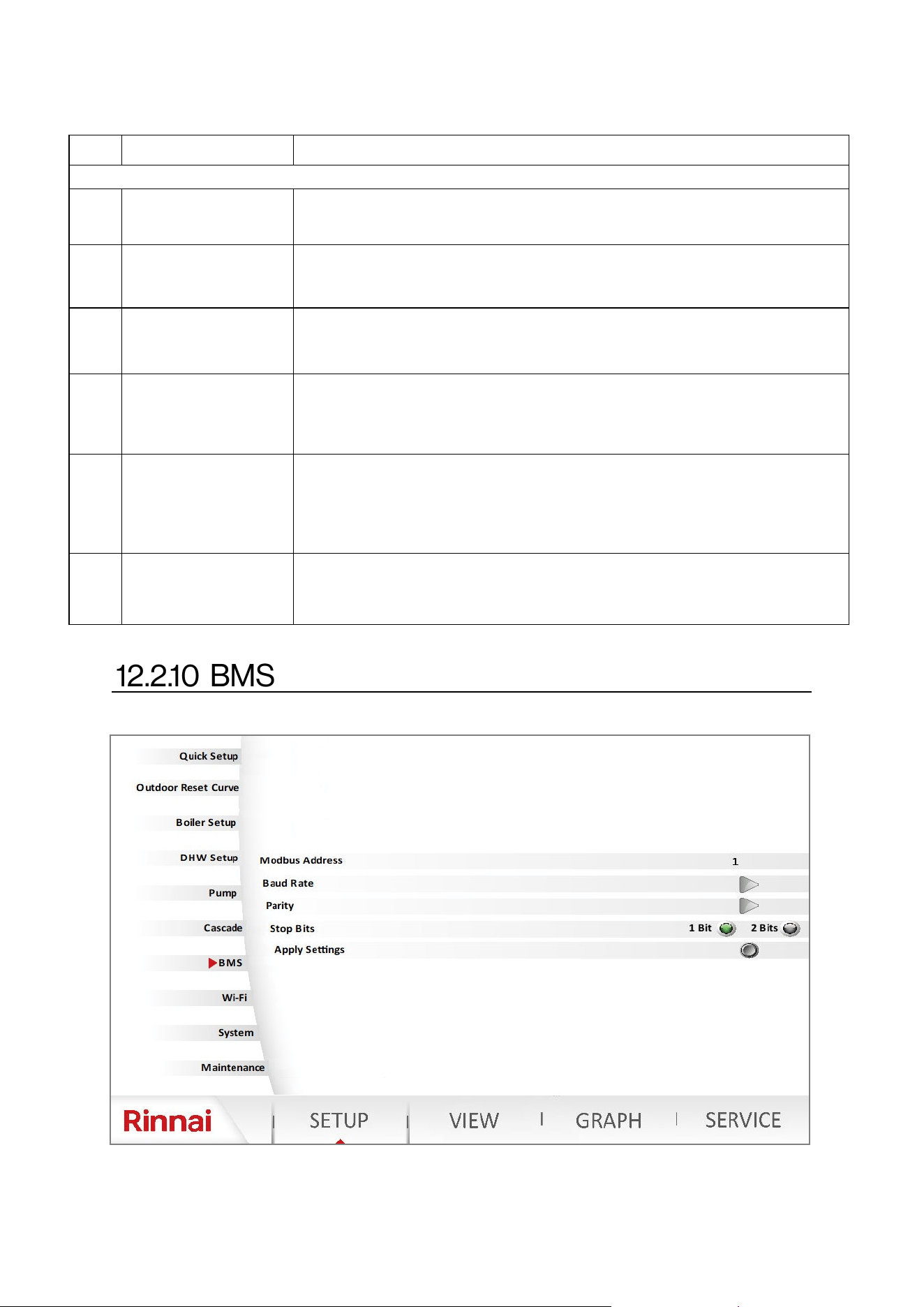
88 Rinnai Commercial Boiler Installation and Operation Manual
NO. DESCRIPTION FUNCTION
Cascade (cont.)
11
Cascade Rotaon
Exclusion
This parameter excludes unit from cascade rotaon.
Range: None, First, Last, First and Last. Default: None
12 Cascade System Sensor
Assigns cascade supply sensor BX1 connecon as B10, cascade system sensor.
Range: On-O; Default: O
NOTE: This parameter must be on for a proper operaon of a cascade system.
13
Forced
Time Basic Stage
Unit will run at min rate and wait for the set me before starng to modulate .
Range: 0-1200 Seconds; Default: 60 Seconds
14 Switch-on Delay - DHW
Sets the wait me to release units in a cascade system during a DHW demand.
For instance when a unit is released for a DHW demand in a cascade system
due to the modulaon load, this unit will wait for this set me before igning
the burner. Range: 0-120 Minutes; Default: 2 Minutes
15. Cascade Master
As soon as more than one heat source is present, the controller with unit
address 1 assumes the role of cascade master. It acvates the required
funcon and shows the addional operang menus with the cascaded related
parameters. Detecon of the master role can be automac (Auto) or can be
switched as xed (always). Range: Auto-Always; Default: Auto.
16 Setpoint Compensaon
This funcon will add an oset value to the boiler setpoint above the cascade
system sensor temperature setpoint.
Range: 1-100; Default: 36°F [20°C]
Table 38 connue
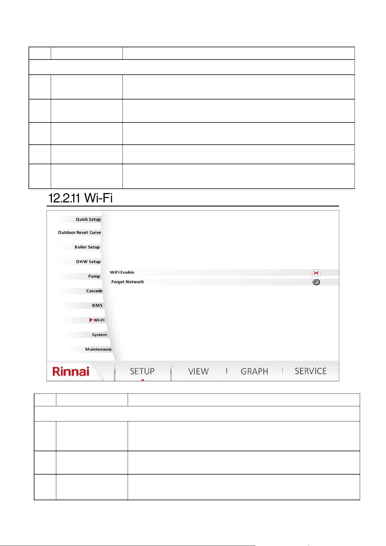
Rinnai Commercial Boiler Installation and Operation Manual 89
NO. DESCRIPTION FUNCTION
BMS
1 Modbus Address
Sets the Modbus Address for BMS.
Range: 0-2; Default: 1
2 Baud Rate
Sets the Baud Rate for BMS.
Range: 4800, 9600, 19200, 38400, 115200; Default: 1115200
3 Parity
Sets the Parity for BMS.
Range: None, Even, Odd; Default: Even
4 Stop Bits
Sets the Stop Bits for BMS.
Range: 1 Bit - 2 Bits; Default: 1 Bit
5 Apply Seng
This parameter is used to apply the sengs aer making changes to the
parameters listed above.
Table 40
Table 39
NO. DESCRIPTION FUNCTION
BMS
1
Wi-Fi or Ethernet
Enable/Disable
This Parameter is used to enable or disable Wi-Fi or Ethernet connecvity.
Range: On-O; Default: O. NOTE: ONLY enable Wi-Fi when connecng the
boiler to a router.
2 Forget Network
This funcon is available in case there is a need to forget the current Wi-Fi
connecvity and connect to a new Wi-Fi. Press the icon to forget network.
3 Ethernet Sengs
This parameter is used to congure Ethernet connecon (enable or disable
DHCP). Use this funcon to congure IP address, Subnet Mask, and Default
Gateway.
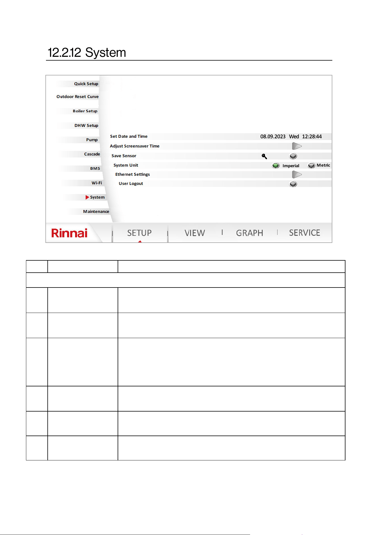
90 Rinnai Commercial Boiler Installation and Operation Manual
NO. DESCRIPTION FUNCTION
System
1 Set Date and Time
This funcon can be used to set the current Date and Time . The user also has
opons to select a me zone. The clock will adjust automacally for day light
savings based on me zone.
2
Adjust Screensaver
Time
Sets the screensaver me. This me is also related to how long the system will
maintain the Installer, Technician, or Engineer logged in.
Range: 1-99 Minutes; Default: 10 Minutes
3 Save Sensor
At midnight, the controller saves the statuses at the sensor terminals, provided
controller has been in operaon for at least 2 hours. If a sensor drops out aer
saving, the controller generates an error message. This seng is used to
ensure immediate saving of sensors. This becomes a requirement when, for
instance, a sensor is removed because it is no longer needed.
Range: On - O Default: O
4 System Unit
Use this funcon to change the system of units from Imperial (F, Psi, Btu) to
Metric (C, Bar, kWh), or vice-versa.
Range: Imperial - Metric O; Default: Imperial
5 Ethernet Sengs This funcon can ONLY be accessed by a Rinnai employee.
6 User Logout
This funcon can be used to logout of SETUP or SERVICE pages, and to change
user level once logged in.
Table 41
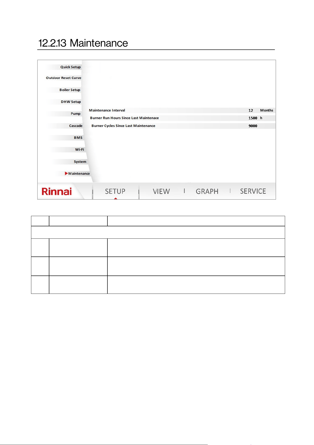
Rinnai Commercial Boiler Installation and Operation Manual 91
NO. DESCRIPTION FUNCTION
Maintenance
1 Maintenance Interval
Sets the boiler maintenance interval in months.
Range: 1-240 Months; Default: 12 Months
2
Burner Hours Since
Last Maintenance
Sets the boiler maintenance interval based on burner run hours.
Range: 100 - 10,000 Hours; Default: 1500 Hours
3
Burner Cycles Since
Last Maintenance
Sets the boiler maintenance interval based on ignion cycles.
Range: 100 - 65,500 Cycles; Default: 9000 Cycles
Table 42
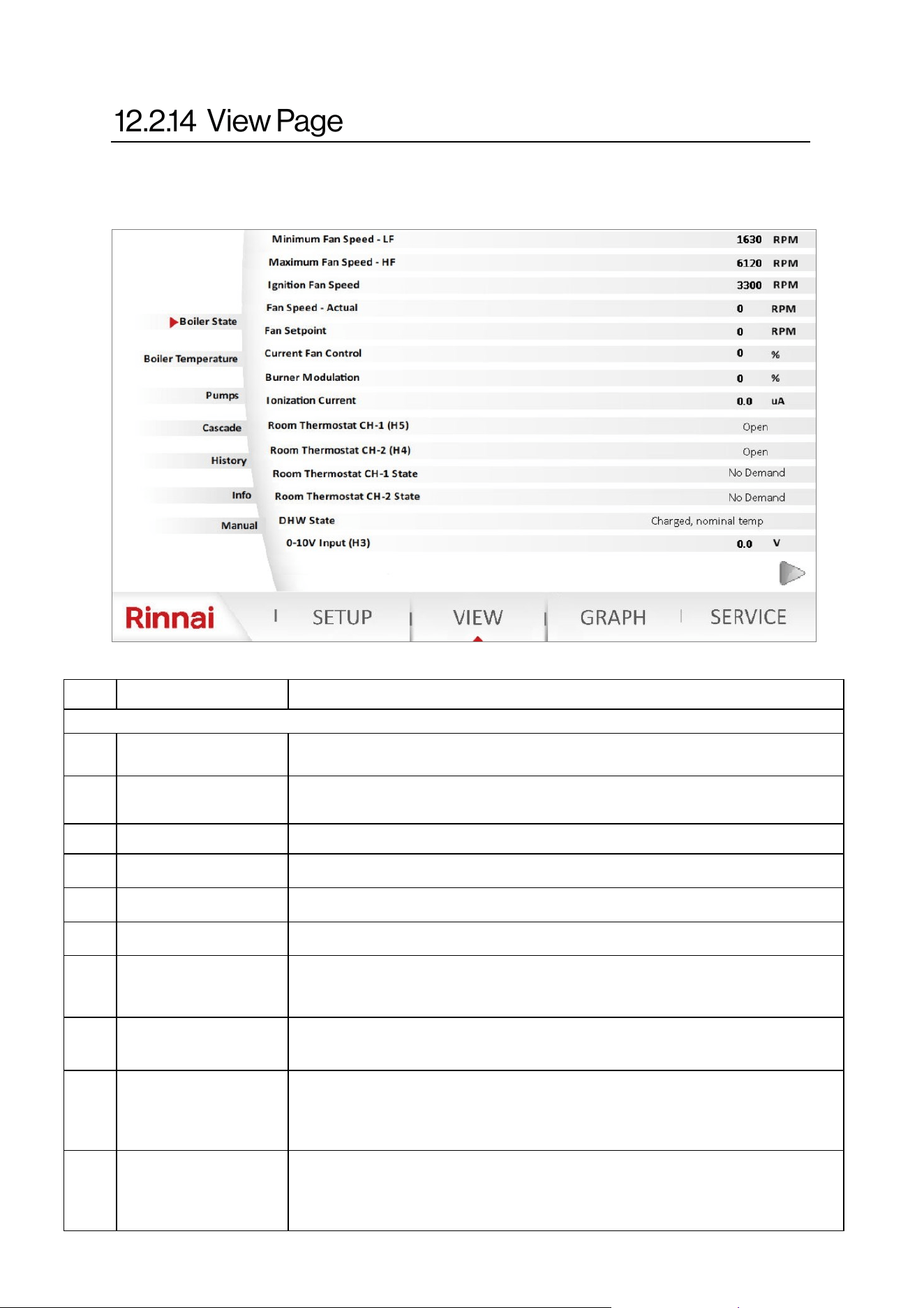
92 Rinnai Commercial Boiler Installation and Operation Manual
VIEW - Boiler State:
The view funcon can be used to monitor boiler operaon. NOTE: Password is not required to
access this page.
NO. DESCRIPTION FUNCTION
Boiler State
1 Minimum Fan Speed
Displays the minimum fan speed setpoint of the boiler based on model, gas
type, and elevaon
2 Maximum Fan Speed
Displays the maximum fan speed setpoint of the boiler based on model, gas
type, and elevaon
3 Ignion Fan Speed Displays boiler ignion speed setpoint
4 Fan Speed Actual Displays the current fan speed
5 Fan Setpoint Displays the current fan setpoint
6 Current Fan Control Displays the current fan PWM (as a percentage)
7 Burner Modulaon
Displays the current boiler modulaon from 0% - 100%. 0% represents the
minimum boiler input rate, and 100% represents the maximum boiler input
rate.
8 Ionizaon Current
Display the current ionizaon current of the ame in uA. The boiler will
exnguish the ame when the ionizaon current is less than 0.8 uA.
9 Room thermostat CH-1
Displays the status of the room thermostat CH-1 connecon. The contact is
normally open and will display open when a room thermostat is not connected
or the demand for heat is o. The state will change to closed when a room
thermostat is connected and calling for heat demand.
10 Room thermostat CH-2
Displays the status of the room thermostat CH-2 connecon. The contact is
normally open and will display open when a room thermostat is not connected
or the demand for heat is o. The state will change to closed when a room
thermostat is connected and calling for heat demand.
Table 43
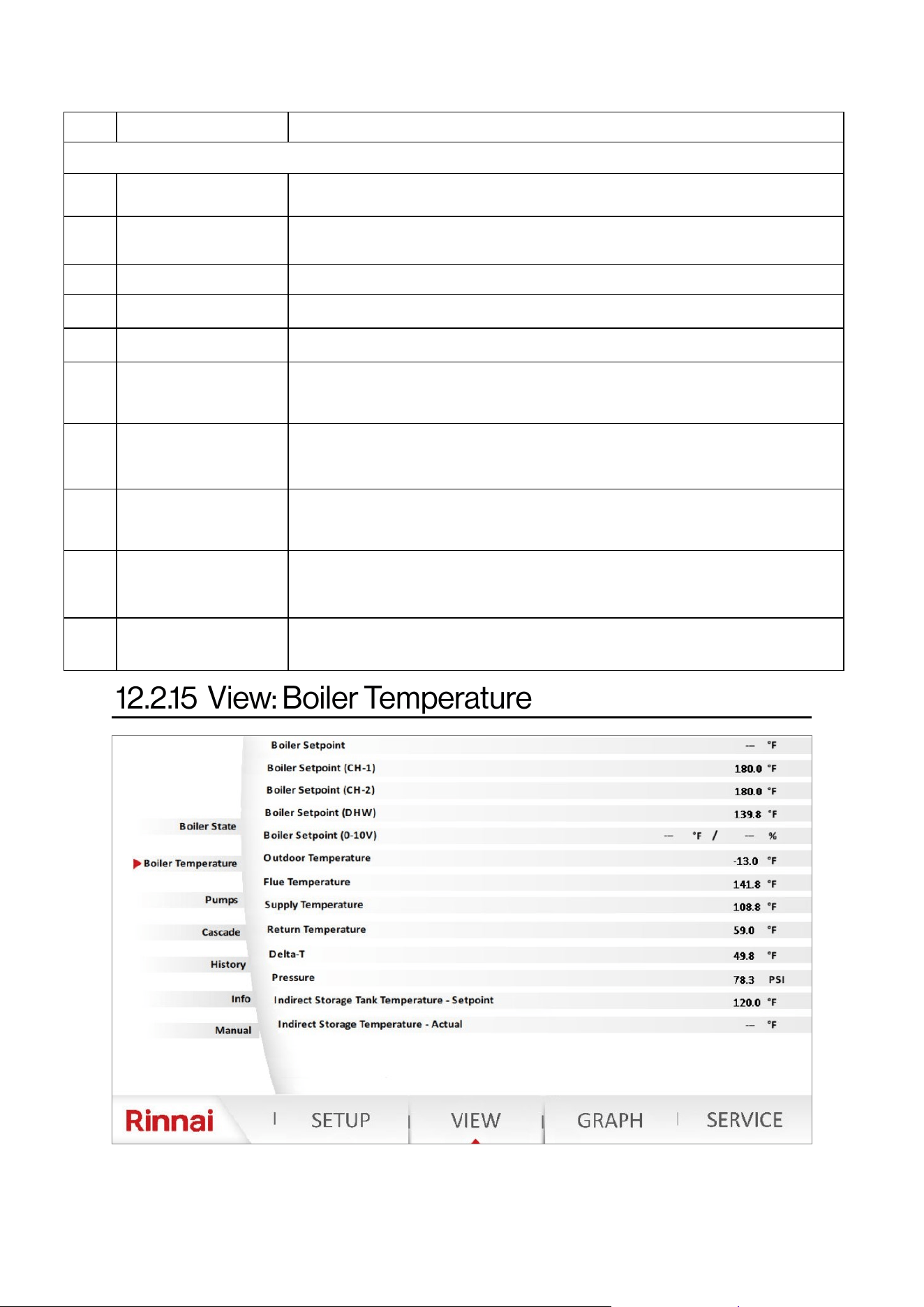
Rinnai Commercial Boiler Installation and Operation Manual 93
NO. DESCRIPTION FUNCTION
VIEW - Boiler State (cont.)
11
Room Thermostat CH-1
State
Display a message regarding the state of the room thermostat CH-1
12
Room Thermostat CH-2
State
Display the a message regarding state of the room thermostat CH-1
13 DHW State Display the a message regarding DHW demand state
14 0-10VDC Input (H3) Displays 0-10VDC input signal to control the boiler temperature setpoint
15 Boiler State Displays the current status of the boiler
16 Burner State
Displays the current status of burner operaon (standby, pre-purge, post-
purge, running, …)
17 Water Pressure Sensor
The water pressure sensor state is normally closed when water pressure
voltage is more than 5VDC. Below 5VDC the state will change to open and the
control will generate an error code.
18
Water Pressure Sensor
Voltage
Displays the current input voltage for water pressure sensor
19 Air Pressure Switch
The air pressure switch is normally closed during normal operaon. The switch
will open in case of a vent or condensate blockage and the control will
generate an error code.
20 Safety Input
Displays the status of the external safety inputs (High and Low Gas Pressure
Switches, Water Temperature High Limit, LWCO).
Table 43 connue
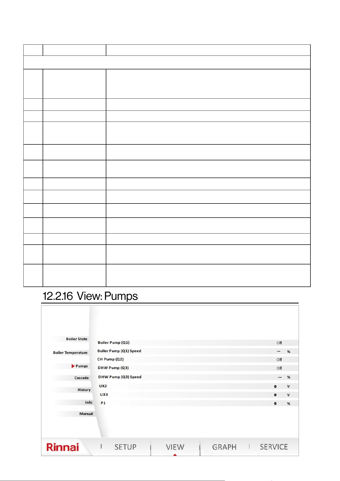
94 Rinnai Commercial Boiler Installation and Operation Manual
NO. DESCRIPTION FUNCTION
VIEW - Boiler Temperature
1 Boiler Setpoint
Displays the boiler acve temperature setpoint. In case there are demands
from both room thermostats (CH-1 and CH-2), the boiler setpoint will be the
highest setpoint. NOTE: A mixing valve must be used to protect the lower
temperature zone.
2 Boiler Setpoint (CH-1) Displays the boiler acve setpoint of room thermostat CH-1
3 Boiler Setpoint (CH-2) Displays the boiler acve setpoint of room thermostat CH-2
4 Boiler Setpoint (DHW)
Displays the boiler acve setpoint for an indirect tank demand. This setpoint is
equal to DHW temperature setpoint + Boiler Supply Temperature Oset for
DHW (on SETUP—DHW Setup page)
5 Boiler Setpoint (0-10V)
Displays the boiler acve setpoint or modulaon setpoint for 0-10VDC input
demand.
6 Outdoor Temperature
Displays the current outside temperature when an outdoor temperature
sensor is connected to the boiler
7 Flue Temperature Displays the current ue temperature
8 Supply Temperature Displays the actual boiler supply temperature
9 Return Temperature Displays the actual boiler return temperature
10 Delta-T
Displays the actual boiler temperature dierenal (Dierence between Supply
and Return temperatures)
11 Pressure Displays the system pressure from the built-in water pressure sensor
12
Indirect Storage Tank
Temperature—Setpoint
Displays the indirect storage tank acve setpoint
13
Indirect Storage Tank
Temperature—Actual
Displays the actual indirect storage tank temperature. NOTE: This will ONLY
display a value when a temperature sensor is being used to control the indirect
storage tank.
Table 44
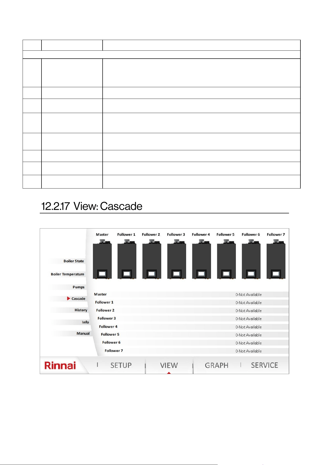
Rinnai Commercial Boiler Installation and Operation Manual 95
NO. DESCRIPTION FUNCTION
VIEW - Pumps
1 Boiler Pump (Q1) Displays the current state of boiler pump (on / o)
2 Boiler Pump (Q1) Speed Not used
3 CH Pump (Q2)
Displays the current state of CH pump (on / o). NOTE: This is for CH-1 room
thermostat connecon zone.
4 DHW Pump (Q3)
Displays the current state of DHW pump (on / o). NOTE: If DHW pump is assigned as a
CH-2 pump from SETUP-DHW Setup page, then this will represent the state of the CH-2
pump for CH-2 room thermostat connecon zone.
5 DHW Pump (Q3) Speed Not used
6 UX2 Displays the value of 0-10V output signal for UX2 connecon
7 UX3 Displays the value of 0-10V output signal for UX3 connecon
8 P1 Displays the PWM value in % for P1 connecon.
Table 45
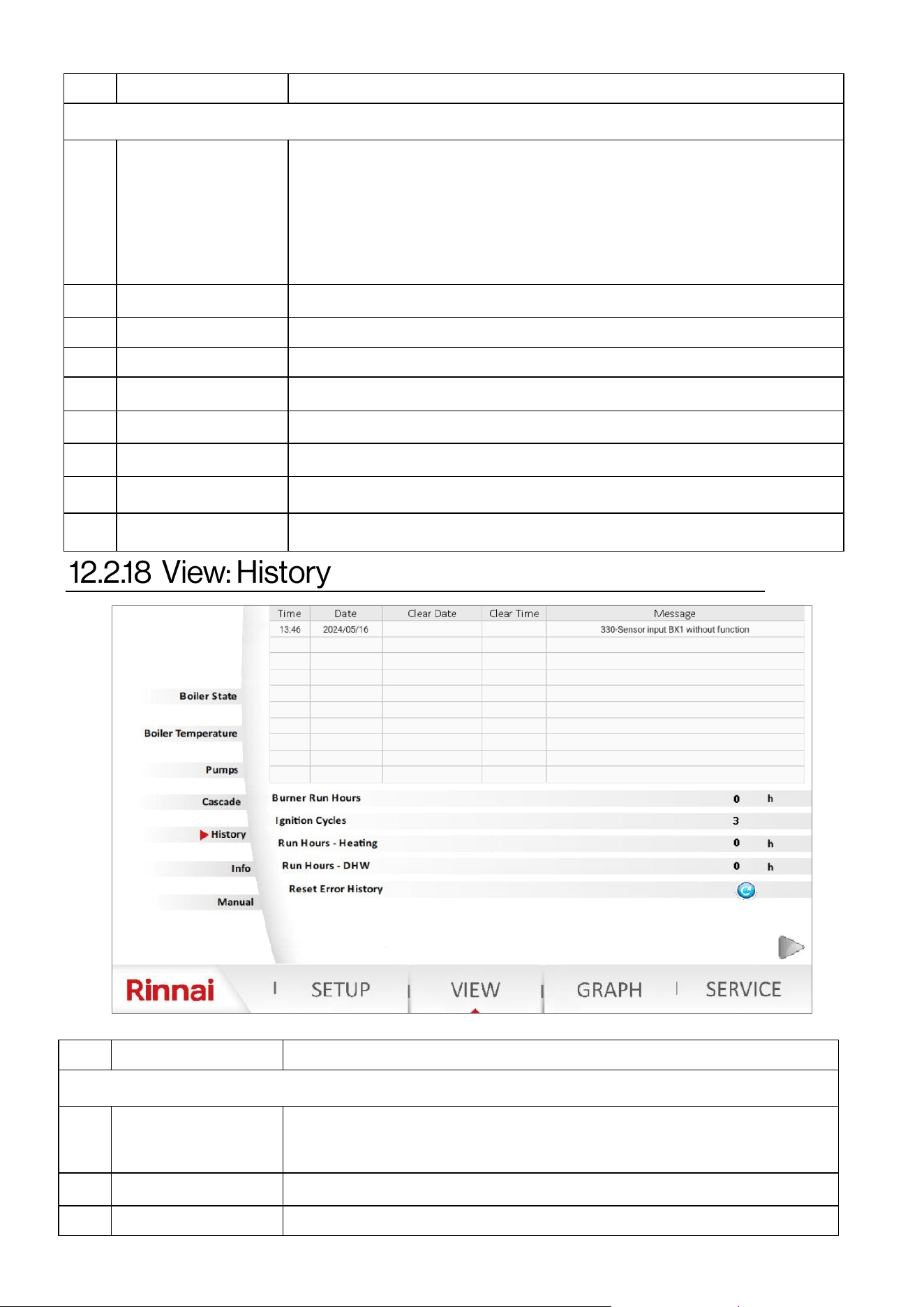
96 Rinnai Commercial Boiler Installation and Operation Manual
NO. DESCRIPTION FUNCTION
VIEW - Cascade
1 Bars explanaon
White Color - Units not available in the cascade system (missing)
Gray Color - Units available and not released for operaon in the cascade system
(standby, or service mode acve)
Yellow - Unit temporarily not available or outside temperature limit acve
Green - Units are released to operate in the cascade system
Red - Unit in a hard lockout state
2 Master Displays the status message of the Master unit.
3 Follower 1 Displays the status message of the Follower 1 unit.
4 Follower 2 Displays the status message of the Follower 2 unit.
5 Follower 3 Displays the status message of the Follower 3 unit.
6 Follower 4 Displays the status message of the Follower 4 unit.
7 Follower 5 Displays the status message of the Follower 5 unit.
8 Follower 6 Displays the status message of the Follower 6 unit.
9 Follower 7 Displays the status message of the Follower 7 unit.
NO. DESCRIPTION FUNCTION
VIEW - History
1 Table explanaon
The table shows historical data of error codes with date and me stamp of when the
error occurred and when the error was resolved. Once the error has been cleared the
line will change color from gray to green.
2 Burner Hours Run Shows total burned run hours
3 Burner Starts Stage 1 Shows total ignion cycles
Table 47
Table 46
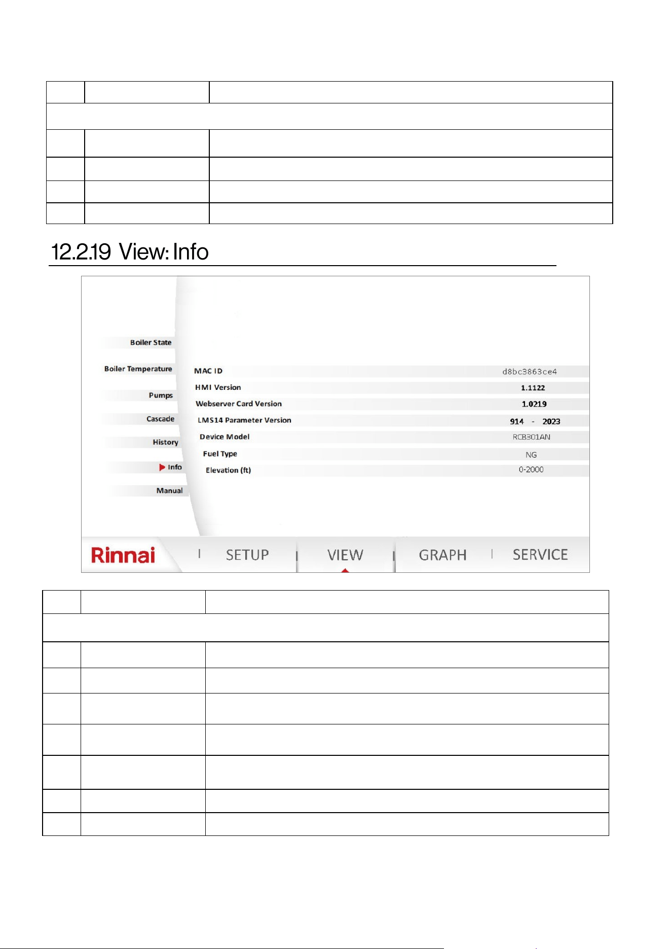
Rinnai Commercial Boiler Installation and Operation Manual 97
NO. DESCRIPTION FUNCTION
VIEW - History (cont.…)
4 Hours Run Heang Displays the run hours for Central Heang (CH) mode
5 DHW Hours Run Displays the run hours for DHW mode
6 Reset Error Code This will clear the error history (ONLY available for Rinnai employees)
7 List of Error Codes This page accumulave error codes. This list can ONLY be reset by a Rinnai employee.
NO. DESCRIPTION FUNCTION
VIEW - Info
1 MAC ID Displays boiler MAC ID for Wi-Fi connecon
2 HMI Version Displays the rmware version of the touch panel—HMI
3 Webserver Card Version
Displays the rmware version of the webserver card (located on the boom of the
boiler)
4 LMS14 Parameter Version Display the parameter le version of the main control board (LMS14)
5 Device Model
Displays the boiler model (RCB301AN, RCB399AN, RCB500AN, RCB750AN, OR
RCB1000AN)
6 Fuel Type Displays the fuel type NG or LP
7 Elevaon () Displays the elevaon seng
Table 47 connue
Table 48
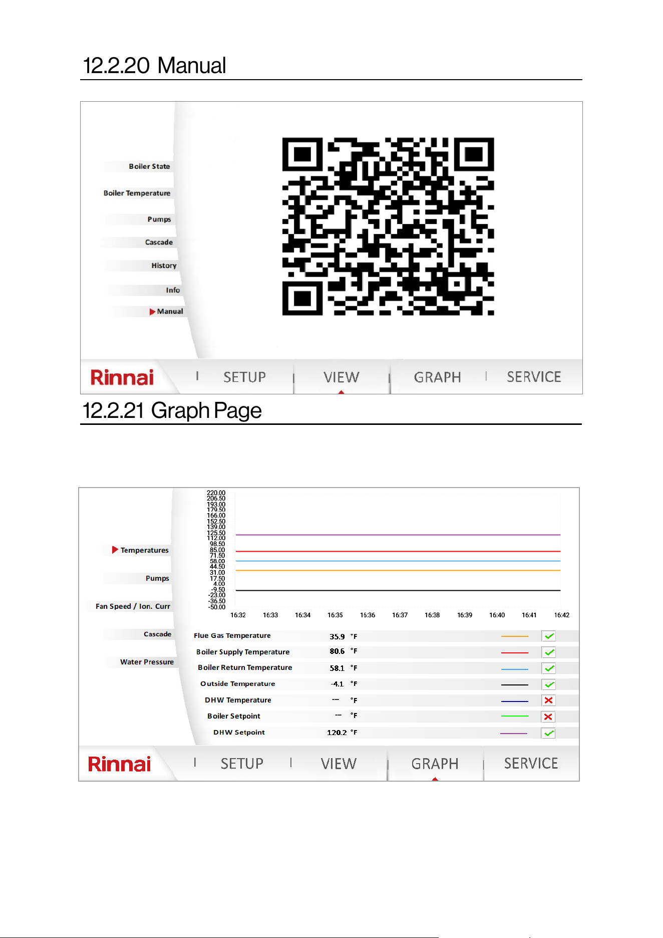
98 Rinnai Commercial Boiler Installation and Operation Manual
The graph function can be used to monitor boiler operation and aid in troubleshooting.
NOTE: Password is not required to access this page.
In order to activate each data point the boxes next to each parameter needs to be activate with a check
mark. As long as the current graphical page remains active a total of 10 minutes, data will be shown on the
screen. Once the user leaves the screen the graph will clear and start from the current time. There are four
different graphs (Temperatures, Pumps, Fan Speed / Ion. Curr., Cascade, and Water Pressure), and ONLY
one of the graphs can be viewed at once.
Scan the QR code on this screen to access the literature for the appliance.
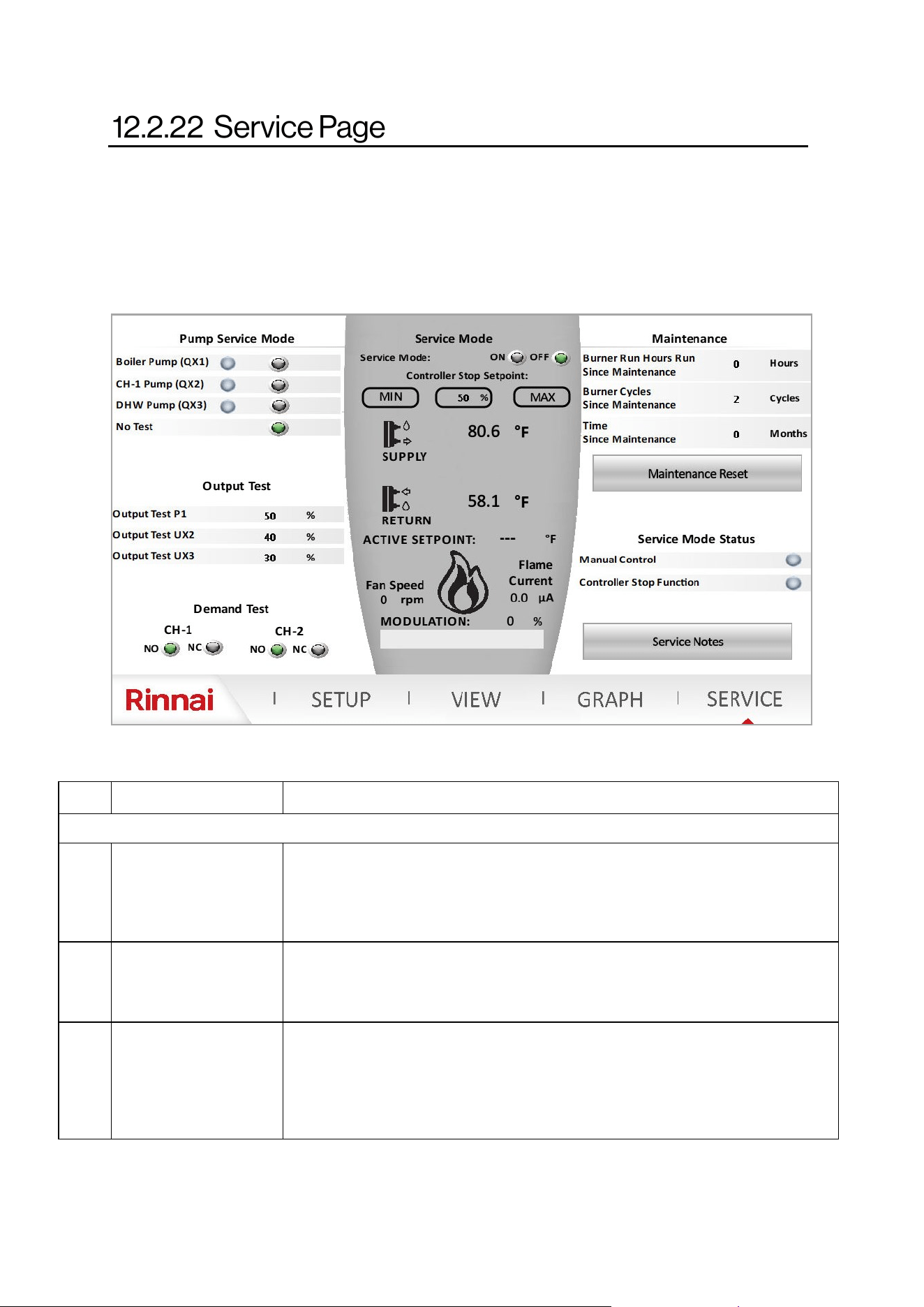
Rinnai Commercial Boiler Installation and Operation Manual 99
The service page can be used during boiler commissioning. This is useful to manually run the pumps and
remove air from the system. Also, it can be used for combuson analysis by running the unit at minimum
and maximum ring rate or any other ring rate in between. NOTE: The service mode operaon will auto-
macally end aer 4 hours unless it is manually turned o by the user. NOTE: It is extremely important to
turn-o the service mode aer boiler commissioning to avoid issues during normal operaon.
NO. DESCRIPTION FUNCTION
LEFT PANE
1 Pump Service Mode
This funcon is used to manually run each one of the pumps individually. This is a
useful means to check pumps for operaon and remove air from the system during
deaeraon process. NOTE: ONLY one pump can be energized at a me. Once the
tesng is completed, press “No Test” to de-energize the pump.
2 Output Test
This funcon can be used to test the operaon of 0-10V and PWM output signals. The
values are in terms of percentage. For instance if the user is looking for 4V, then 40%
should be entered. The readable values can be conrmed from VIEW - Pumps page.
3 Demand Test
This funcon can be used to test funconality of room thermostat connecon without
any wiring connected to the boiler terminals. These contacts are normally open (NO).
By clicking on Normally Closed (NO), this will close the room thermostat connecon
and the boiler will get a demand for heat. NOTE: It is very crical to return these values
to the default seng (NO) once the tesng is completed.
Table 49
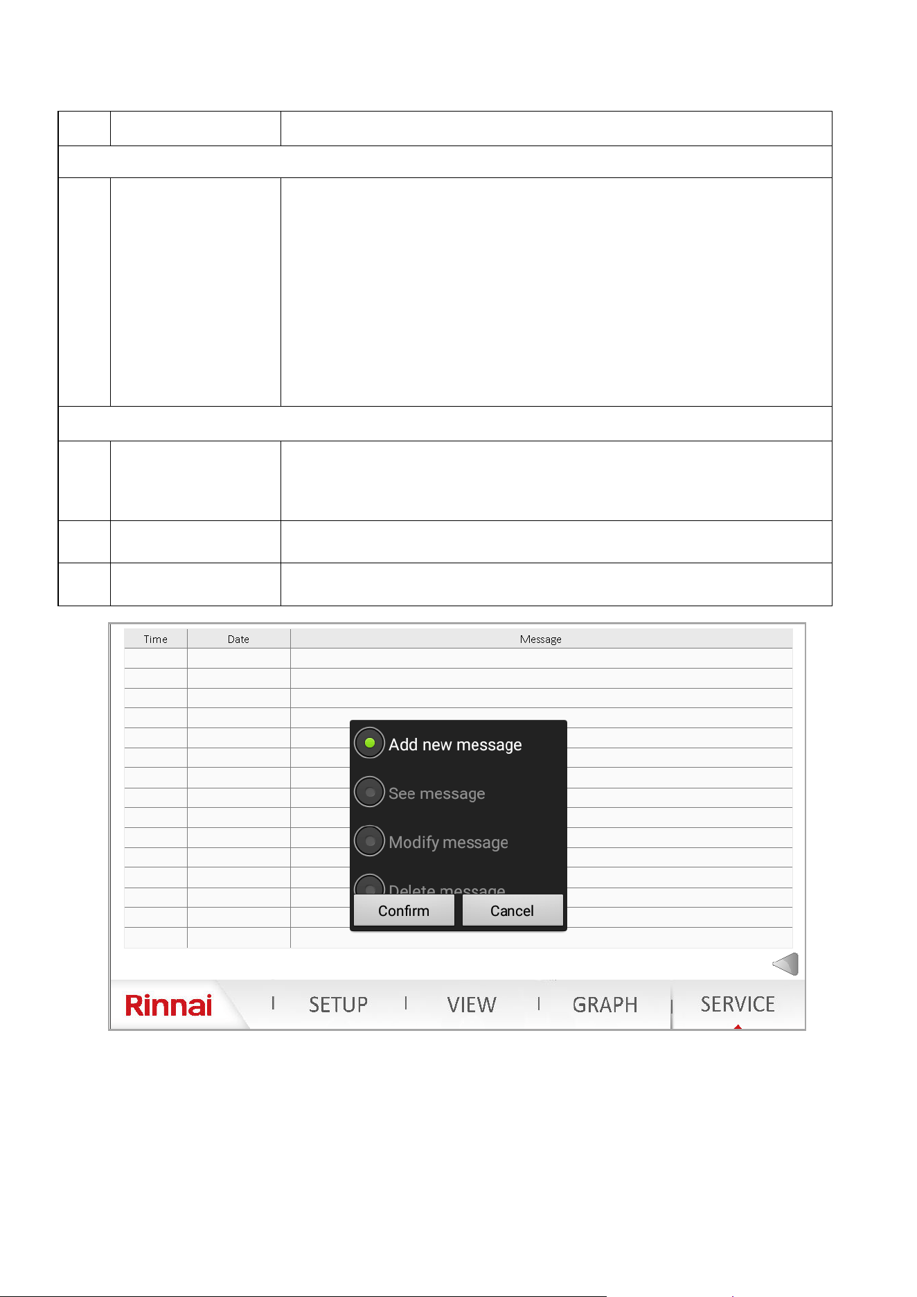
100 Rinnai Commercial Boiler Installation and Operation Manual
NO. DESCRIPTION FUNCTION
CENTER PANE
4 Service Mode
Service mode can be used to manually re the unit and adjust its ring rate. Press on
the ON icon in front of Service mode to acvate a call for heat. Once the demand for
heat is acve, the two LED lights under Service Mode Status (right pane) will illuminate.
The ring rate can be adjusted by clicking on MIN (this will bring the boiler to the
minimum ring rate), MAX (this will bring the boiler to its maximum ring rate), or
percentage box (will prompt the user to enter a value between 0% and 100%).
NOTE: The boiler target setpoint will be 180F once this mode is acve. It is important
for the user to ensure there is enough head load connected to the boiler to dissipate
the heat. During this mode all 3 pumps will be energized, it is also crical to ensure not
to overheat an indirect tank that is connected to the boiler.
The remaining informaon on the center pane are to view ONLY.
RIGHT PANE
5 Maintenance
The informaon showing (Burner Run Hours Since Maintenance, Burner Cycles Since
Maintenance, and Time Since Maintenance) are used to display boiler operaon since
last maintenance service. Once the service has been performed , the user can click on
Maintenance Reset box to reset the counter.
6 Service Mode Stats
This is read only informaon. Once the service mode has been acvated both LED
indicators will turn green to conrm operaon.
7 Service Notes
Click on Service Notes box to enter notes, contact informaon for the record. See info
below for more details.
To add new notes, double tap the screen on an empty line under the message. A conrmaon box will pop-up.
Click on conrm, then a new text box will pop up to for the user to type the informaon. Once the informaon
has been entered, click on conrm to save the content.
To edit previous messages, double click on the desired message. It will be highlighted in blue and conrmaon
will pop-up. Click on Modify Message to make changes to current message, or Delete Message to delete
current selected message.
Table 49 connue
Rinnai Commercial Boiler Installation and Operation Manual 101
Some of the checks below should be performed by a licensed professional.
Consumers should never aempt any acon that they are not qualied to perform.
Error
Code
Message
Remedies
NOTE: The numbers in parenthesis are diagnosc codes associated with each
error code
10
Outdoor sensor fault
(B9)
The error will auto-reset once the issue is resolved (610)
NOTE: This error code does not prevent boiler operaon; However, it will
prevent any other error codes to show on the home page.
1- Check the outdoor sensor connecon to ensure it is not open or not
connected (if not connected, the jumper should remain in place - supplied from
the factory) - check connuity
2- Check outdoor sensor wiring to ensure it is connected properly (1 kOhm
sensor supplied from the factory) - check connuity
3- Check the resistance of the outdoor sensor and compare to the value shown
on the resistance value table
4- Replace the outdoor sensor if malfuncon is detected
5- If the issue persists, replace the main control board
20
Boiler Supply
temperature sensor
fault (B2)
The error will auto reset once the issue is resolved (unless the diagnosc code is
2- manual reset required)
1- Check supply temperature sensor wiring to ensure it is connected properly
(10 kOhm sensor) - check connuity
2- Check supply temperature sensor to ensure it is not short or open (2)
3- Check the resistance of the supply temperature sensor and compare to the
value shown on the resistance value table (737, 591, 249, 552)
4- Replace the supply temperature sensor if malfuncon is detected.
5- If the issue persists, replace the main control board
26
Cascade temperature
sensor fault (B10)
The error will auto-reset once the issue is resolved
NOTE: This error code does not prevent boiler operaon; However, it will
prevent any other error codes to show on the home page.
1- Check cascade temperature sensor wiring to ensure it is connected properly
(10 kOhm sensor)
2- Check cascade temperature sensor to ensure it is not short or open
3- Check the resistance of the cascade temperature sensor and compare to the
value shown on the resistance value (Table 51: Temperature vs. Resistance).
The cascade temperature sensor is ONLY required on the Master boiler.
Conrm the cascade address is set correctly. Ensure the cascade sensor is set
correctly on SETUP - cascade setup page. If everything is set correctly, use the
save sensor opon on SETUP - system setup to congure this sensor.
4- Replace the supply temperature sensor if malfuncon is detected.
5- If the issue persists, replace the main control board
WARNING
The list of error codes with occurrence day and me and with clear date and me are saved in the History page.
This informaon can be accessed via the boiler controller by clicking on VIEW - History.
Table 50

102 Rinnai Commercial Boiler Installation and Operation Manual
Error
Code
Message
Remedies
NOTE: The numbers in parenthesis are diagnosc codes associated with each
error code
28
Flue gas
temperature
sensor fault (BX3)
The error will auto reset once the issue is resolved (unless the diagnosc code is
0 or 540 - manual reset required)
1- Check ue gas temperature sensor wiring to ensure it is connected properly
(10 kOhm sensor) - check connuity
2- Check ue gas temperature sensor to ensure it is not short (543 or 0) or
open (544 or 540)
3- Check the resistance of the ue gas temperature sensor and compare to the
value shown on the resistance value (Table 51: Temperature vs. Resistance).
4- Replace the ue gas temperature sensor if malfuncon is detected.
5- If the issue persists, replace the main control board
40
Return
temperature
sensor fault (B7)
The error will auto reset once the issue is resolved (unless the diagnosc code is
0- manual reset required)
1- Check return temperature sensor wiring to ensure it is connected properly
(10 kOhm sensor) - check connuity
2- Check return temperature sensor to ensure it is not short (441) or open (442)
3- Check the resistance of the return temperature sensor and compare to the
value shown on the resistance value table (52, 738, 250, 0)
4- Replace the return temperature sensor if malfuncon is detected.
5- If the issue persists, replace the main control board
50
DHW
temperature
sensor/
thermostat fault
(B3)
The error will auto-reset once the issue is resolved (55)
NOTE: This error code does not prevent boiler operaon; However, it will
prevent any other error codes to show on the home page.
1- Check what type of device is used to control the indirect tank temperature
(sensor or aquastat). Verify that the sengs on the boiler (SETUP-DHW Setup)
match the applicaon
2- Check the DHW temperature sensor connecon to ensure it is not open or
not connected (if an aquastat is being used ensure the correct seng is used on
SETUP-DHW setup page)
3- Check DHW temperature sensor wiring to ensure it is connected properly (10
kOhm sensor) - check connuity
4- Check the resistance of the DHW temperature sensor and compare to the
value shown on the resistance value table
5- Replace the DHW temperature sensor / Aquastat if malfuncon is detected
6- If the issue persists, replace the main control board
81
LPB short-circuit
or no bus power
supply
The error will auto-reset once the issue is resolved (67)
1- Check cascade communicaon cable to ensure the wires are not shorted
2- Ensure the cable connecon from cascade module to the main control board
is connected properly and secured
3- If the problem persists and the unit is not cascaded with other units,
disconnect the cascade module from the main controller.
NOTE: LPB is the cascade bus (the power comes directly form the main
controller)
82
LPB address
collision
The error will auto-reset once the issue is resolved (67)
NOTE: This error code will ONLY happens if there are two or more units
connected with each other.
1- Check to ensure the cascade addresses for the units in the cascade system
are unique. For instance if there are one or more units set as Master, the LPB
address collision error code will be displayed.
Table 50 connue

Rinnai Commercial Boiler Installation and Operation Manual 103
Error
Code
Message
Remedies
NOTE: The numbers in parenthesis are diagnosc codes associated with each
error code
83
BSB-Wire short-circuit
or no communicaon
The error will auto reset once the issue is resolved (595)
1- Ensure the wiring from the Webserver card/Wi-Fi Module and LMS is not
jumped or disconnected.
NOTE: BSB is the communicaon between the Webserver card/Wi-Fi Module and
main controller.
91
Data loss in EEPROM The error will auto reset once the issue is resolved (618)
This error code should only happen during ashing of the main controller at the
factory.
1- Loss of data on EEPROM - replace the main control board
105 Maintenance message
The error will auto reset once the maintenance interval has been reset (87)
1- Perform the boiler service as recommended by the manufacturer
2- Once the service has been performed, access the SERVICE page and perform a
maintenance reset.
110
SLT lock-out
SLT - Safety Limit
Thermostat (electronic)
This error code requires a manual reset
1- Boiler return temperature not possible (< 32°F [0°C]) - (424)
2- Boiler supply temperature not possible (<32°F [0°C]) - (422)
3- Boiler supply temperature not possible (>255°F [124°C]) - (422, 809 )
4- Safety Limit Thermostat (SLT) is open (551, 412) - check connuity of
thermofuse, burner door switch and jumper on high voltage terminal block)
5- Boiler return temperature > 208°F (98°C) - (425)
6- Boiler Supply Temperature > 208°F (98°C) - (419, 430, 432)
7- Boiler temperature rises faster than allowed (5.4°F [3°C]) - (426, 437)
8- Reset criteria (boiler temperature less than boiler temperature setpoint and
Delta-T less than 72°F [40°C] for error 426 not reached - (427)
9- Delta T (dierence between supply and return) is higher than 101°F (56°C) -
(428)
10- Reset criteria (Delta-T less than 36°F [20°C] aer error 433 not reached)-(429)
11- Boiler return temperature is higher than boiler supply temperature + 27°F
(15°C) - (420, 431)
12- Boiler return temperature is higher than/equal to boiler supply temperature
+ 31°F (17°C) - (420)
13- Supply temperature increases aer the burner is o - residual heat (436)
14- Delta-T (dierence between supply and return) is greater than 72°F [40°C) -
(433, 438)
15- Supply temperature exceeds 208°F (98°C) - (432)
111
Temperature limiter
safety shut-down
The error will auto reset once the supplied temperature is below 203°F (95°C)
(264)
1- Supply temperature has exceeded 203°F (95°C) (264)
117
Water pressure too high
(H1)
The error will auto reset once the water pressure decreases to less than 83 PSI
(5.7 bars) (566)
1- Ensure the water pressure in the system does not exceed 87 PSI (6 bar). This is
very unlikely since the maximum seng on the factory supplied pressure relieve
valve is 75 PSI
2- If the actual pressure in the system has been conrmed to be below 87 PSI,
replace the water pressure sensor.
118
Water pressure too low
(H1)
The error will auto reset once the water pressure is at least 16 PSI (1.1 bar) (566)
NOTE: The boiler will reduce the output power when pressure in the system is
between 12 PSI (0.8 bar) - 20 PSI (1.4 bar). The boiler will connue to operate and
an error code will be displayed on the home screen. When the pressure increases
above 20 PSI (1.4 bar) the error will disappear. If the pressure decreases below 12
PSI (0.8 bar) the boiler will shut-down and keep the error code.
1- Ensure the water pressure in the system is at least 12 PSI (0.8 bar). Check the
pressure seng on the water auto feed to the boiler loop. Check for water leaks
in the system piping.
2- If the pressure in the system is sll below 16 PSI (1.2 bar), replace the water
pressure sensor.
Table 50 connue

104 Rinnai Commercial Boiler Installation and Operation Manual
Error
Code
Message
Remedies
NOTE: The numbers in parenthesis are diagnosc codes associated with
each error code
125
Maximum boiler
temperature exceeded
Boiler pump and fan
will connue to run to
dissipate the heat.
The error will auto reset once the boiler supply temperature decreases
below 203F (95C) minus the boiler switch on dierenal, 20°F (11°C) -
default sengs.
NOTE: The boiler will start reducing the ring rate when supply
temperature reaches 190°F (88°C)
1- The boiler temperature has reached 203F (95C) (286, 500, 740)
2- No temperature change on supply sensor aer ame (501)
3 - No temperature change on return sensor aer ame (502)
128
Loss of ame in
operaon (10 mes)
This error code requires a manual reset
1- Loss of ame in operaon (625)
2- Ionizaon current has fallen below 0.8uA (854)
3- Ensure the boiler electrical connecon is properly grounded to the
ground source.
4- Monitor the gas pressure to the unit while in operaon. The gas
pressure should be within the limits specied in this manual.
5 - Check the ame signal on the display. It should be above 0.8uA when
the burner is lit. The ame current should be stable aer the boiler has
been ring for at least one minute and it is normally between 3 - 7uA. if
the ame current is less than 0.8uA, disassemble the burner door and
check the ionizaon probe quality and distance to the burner (clean if
necessary).
130
Flue gas temperature
maximum limit
exceeded (BX3)
This error code will automacally reset if the issue is resolved within 10
minutes. Otherwise a manual reset is required.
1- Ensure the proper seng is being used for the ue pipe venng
material. If the ue temperature for the applicaon is higher than 149°F
(65C), vent material other than PVC must be used and the seng for
the ue gas temperature limit must be set to other on the controller
(SETUP-Boiler Setup).
2- The control will limit the ue temperature to 149°F (65°C) for PVC
pipe and 207°F (97°C) for other venng materials. The boiler will
automacally start to modulate when the vent temperature reaches
140F (60°C for PVC and 194°F (90°C) for other venng material. The
control will shut down and monitor the vent temperature for 10
minutes. If the temperature exceeds the value shown here aer 10
minutes the control will lock-out.
3- Check ue gas temperature resistance and compare to the value
listed on the resistance table
4- Ensure the correct gas type is used. If the unit is Natural Gas and
Propane gas is connected to the unit this will cause boiler overheang
and unsafe condions.
133
Safety me for
establishment of ame
exceeded (4 mes)
This error code requires a manual reset
1- The boiler failed to ignite four mes during one heat call (625)
2- Check electrical connecon to the unit and check for proper
grounding and polarity.
3 - Check the ignion transformer wiring connecon for reverse
polarity.
4- Check for sparks through the sight glass on the burner door.
5- If there is spark but no ame, monitor the stac gas pressure to
ensure it is within the limits specied in this manual
6- Check for vent or condensate blockage.
7- If the problem persists, remove the burner door and inspect the
ignion electrodes (check for gaps and distance to the burner. Clean if
necessary)
Table 50 connue

Rinnai Commercial Boiler Installation and Operation Manual 105
Error
Code
Message
Remedies
NOTE: The numbers in parenthesis are diagnosc codes
associated with each error code
151 BMU internal fault
This error requires a manual reset
Internal error on the main controller (630)
1- Error at closing(330) or opening (331) ignion relay
2- Error at closing (332) or opening (333) gas valve relay 1
3- Error at closing (336) or opening (337) the safety relay
4- Replace the main controller
152 Parameterizaon error
This error will auto-reset once the issue is resolved unless
diagnosc code is 780, 781, 782, 851, 840 or 853 - manual reset
required
This error happens when seng parameters on the main
controller. For instance if the fan speeds are not set within the
min and max range set on the main controller.
153 Unit manually locked
This error code requires a manual reset (press reset buon for
less than 10 seconds)
1- Unit manually locked (reset buon pressed more than 10 sec-
onds)
160
Fan speed threshold not
reached
This error code requires a manual reset
NOTE: These error codes happen in case the impeller on the fan
gets stuck.
1- Fan speed threshold not reached: home run (377)
2- Fan speed threshold not reached: standby (378)
3- Fan speed threshold not reached: ignion (379)
4- Fan speed threshold not reached: pre-purge (380)
5- Fan speed threshold not reached : post-purge (381)
6- Fan speed threshold not reached : in operaon (233, 749)
162
Air pressure switch does
not close
This error code requires a manual reset (9)
1- Air pressure switch is normally closed and will open in case of
condensate or vent blockage.
2- Check the pressure switch wiring—check connuity.
3- Check vent pipe and condensate trap for blockage.
Disconnect the hose from the air pressure switch and check for
operaon. If the unit operates normal, either condensate on
vent pipe is blocked. If the unit does not operate check pressure
switch.
4- Check the pressure switch wiring to ensure it is normally
closed when the unit is on standby.
5- If the issue persists replace the air pressure switch.
164
Flow/pressure switch
HC fault
This error will auto-reset once the issue is resolved
1– Water ow is not detected aer receiving a heat demand
(562)
2– Ensure the pump is operaonal and providing adequate ow
rate.
3– Ensure the ow switch is connected properly and facing the
ow direcon.
4– Ensure the return and supply pipes are connected correctly.
5– Check connuity to ensure the ow switch contact is closed
when there is no water ow and closed with water ow.
183
Unit in parameteriza-
on mode
This error code requires a manual reset
1- Unit in parameterizaon mode (301)
2- Unit in parameterizaon mode (770 - parameter sck)
Table 50 connue

106 Rinnai Commercial Boiler Installation and Operation Manual
Error
Code
Descripon
Remedies
NOTE: The numbers in parenthesis are diagnosc codes associated with each
error code
217 Sensor fault
This error code will auto-reset once the issue is resolved
1- Short-circuit of ionizaon electrode (765, 766). The ionizaon current is
shorted to ground.
2- Check the condensate trap to ensure the condensate is draining properly. If
there is water in the heat exchanger in contact with the ionizaon electrode
this error code will appear.
317
Grid frequency OOR This error code will auto-reset once the frequency is back within the range
NOTE: This error code happens when the power frequency is out of the range
[42 Hz - 72 Hz]
1- Mains frequency outside specicaon (275, 461)
353
Cascade temperature sen-
sor missing (B10)
This error code will auto-reset once the issue is resolved
NOTE: On a cascade system, a cascade temperature sensor is required to be
installed on the system loop. Once a sensor is connected to the unit, the main
controller recognized the sensor. If the sensor gets disconnected this error code
will be shown. If the unit is no longer set as a cascade, the sensor must be disa-
bled from the cascade setup menu, and save sensor funcon must be applied
from the system setup menu.
1- Cascade temperature sensor missing (B10) (139)
384
Extraneous light This error code requires a manual reset (625)
NOTE: This error code happens if unit detects fan while the gas valve is not en-
ergized (false ame)
385
Main under voltage This error code will auto-reset once the voltage is back within the range
NOTE: This error code happens when the voltage is out of the range [102V -
132V]
1- Voltage outside of the range (554, 555)
386 Fan speed tolerance
This error code requires a manual reset
1- Fan speed out of tolerance (+/-300 rpm): home run (387)
2- Fan speed out of tolerance (+/-300 rpm): standby (388)
3- Fan speed out of tolerance (+/-1200 rpm): ignion (374, 382, 383)
4- Fan speed out of tolerance (+/-1200 rpm): pre-purge (389,531)
5- Fan speed out of tolerance (+/-1200 rpm): post-purge (390, 532, 534)
6- Fan speed out of tolerance (+/-1200 rpm): in operaon (232, 750, 375, 385,
386)
Other possible issues without an error code:
1. There is call for heat, pumps are running however the unit is not ring. Check boiler acve setpoint and
compare with boiler actual supply temperature values. The boiler will ONLY re when the acve setpoint is
equal or higher than the boiler actual temperature plus the dierenal.
2. The main screen is blank. Ensure the CAT5 cable is properly connected to the main screen (it must be
connected to port RS485). Check the webserver card/Wi-Fi Module located on the boom of the unit to
ensure it is geng power. If so, please check the wiring from webserver card/Wi-Fi Module to the HMI for
proper connecon (see wiring diagram for details).
3. The temperature values on the main screen are all zeros. Ensure the webserver card/Wi-Fi Module is
properly connected to the main controller and is geng power.
Table 50 connue
Rinnai Commercial Boiler Installation and Operation Manual 107
Supply Temperature Sensor
Return Temperature Sensor Flue
Temperature Sensor
Cascade System Sensor
DHW Temperature Sensor
Outdoor Temperature Sensor
Temperature [°F] Resistance [Ω]
Temperature [°F] Resistance [Ω]
-22 13034
-13 9889
-4 7578
5 5861
14 4574
23 3600
32
32555
32 2857
41
25339
41 2284
50
19873
50 1840
59
15699
59 1492
68
12488
68 1218
77
10000
77 1000
86
8059
86 827
95
6535
95 687
104
5330
104 575
113
4372
113 483
122
3605
122 407
131
2989
140
2490
149
2084
158
1753
167
1481
176
1256
185
1070
194
915
203
786
212
677
Table 51: Temperature vs. Resistance
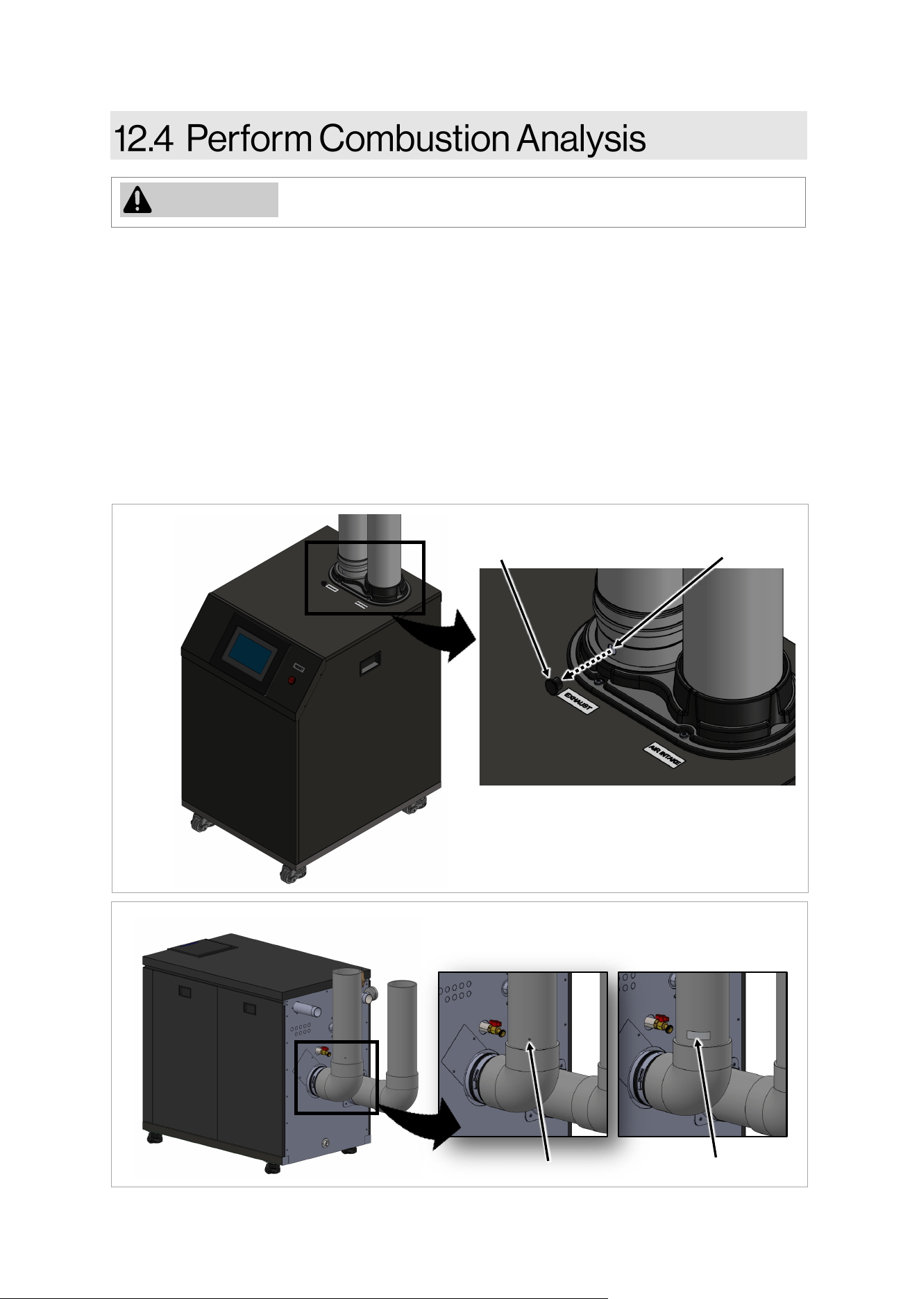
108 Rinnai Commercial Boiler Installation and Operation Manual
WARNING
Combuson analysis must be performed by a trained and qualied
professional.
To perform a combuson analysis:
1. Remove the boiler’s front panel by removing the two screws that secure the panel.
2. 500 model: Remove the combuson analysis port plug and insert the gas analyzer probe into the
port (Figure 56).
750 and 1000 models: Drill a hole on the exhaust pipe to insert the combuson analyzer probe.
Ensure to have a piece of aluminum tape to plug the hole once the test is completed (Figure 57).
3. Use the SERVICE page on the boiler home screen to manually run the unit at maximum and
minimum ring rate to check for proper combuson adjustment. This boiler has an automac
ignion system. When the main burner has lit, the ame symbol will on the home page will
illuminate and the modulaon percentage will show on the home page. The maximum ring rate
is 100% of modulaon and the minimum ring rate is 0% of modulaon.
Figure 56
Figure 57
Test Port Plug
Combuson Analysis Port and Plug
Test Port
Test Port
Aluminum Tape
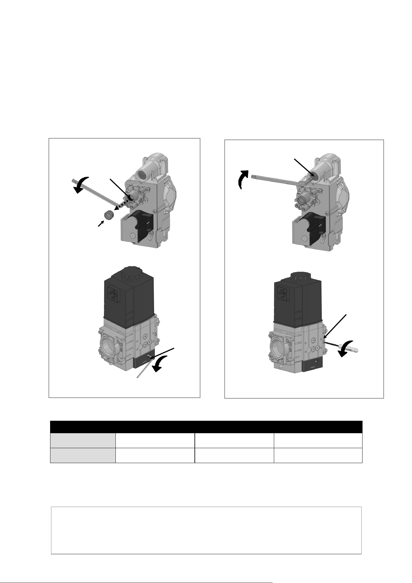
Rinnai Commercial Boiler Installation and Operation Manual 109
TYPE OF GAS CO2 RANGE (%) CO LIMIT (PPM) CO2 TARGET (%)
NG
8.5 - 9.7
< 175 PPM
9.0
PROPANE
9.5 - 10.5
< 175 PPM
10.0
5. For RCB500AN model: Aer measurement, remove the gas analyzer probe, and replace the
combuson analysis port plug.
Add another statement for RCB750AN / RCB100AN models: Aer measurement, remove the
gas analyser probe, and cover the test port (drilled hole) using aluminium tape.
Informaon in table applies to both Minimum and Maximum ring rates.
IMPORTANT: When making adjustments to the gas valve, it is crical to make a small adjustment
rst, then wait for the combuson to sele before making further adjustments. The boiler is
pre-set at the factory and only a slight adjustment should be made to the gas valve for tuning.
Make adjustments to the minimum ring rate rst, and then proceed to the maximum ring rate
adjustment.
Table 52:
4 Use a combuson analyzer to verify CO2 is within the range listed in the table below for both minimum
and maximum ring rates. If a combuson analyzer is not available:
• For minimum ring rate, adjust the oset screw counterclockwise to decrease CO2 and clockwise to
increase CO2 (Figures 58 and 59).
• For maximum ring rate, adjust the throle screw to increase or decrease the CO2. See Figures 60
and 61 for steps on increasing or decreasing CO2.
IMPORTANT: When making adjustments to the gas valve, it is crical to make a small adjustment rst,
then wait for the combuson to sele before making further adjustments. The boiler is pre-set at the
factory and only a slight adjustment should be made to the gas valve for tuning. Make adjustments to the
minimum ring rate rst, and then proceed to the maximum ring rate adjustment.
Throle
Screw
Figure 60
Reduce
Torx Plug
Figure 58
Reduce
Oset
Screw
Adjustment screw is located on both sides of the gas
valve. Only one side needs to be adjusted.
Throle
Screw
Reduce
Figure 61
Adjustment screw is located on both sides of the
gas valve. Only one side needs to be adjusted.
Oset
Screw
Reduce
Figure 59
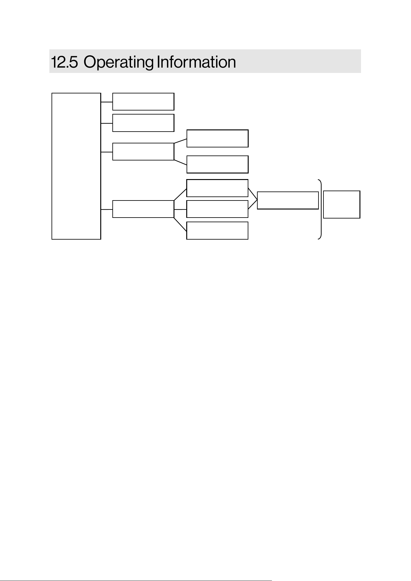
110 Rinnai Commercial Boiler Installation and Operation Manual
Freeze Protecon (priority 1):
The electronic management system of the boiler includes protecon against frost. If the
water temperature falls below 41°F [5°C], the burner starts up and the boiler pump runs to provide
a water temperature of 46°F [8°C] + Boiler Oset 9°F [5°C] + Boiler Dierenal 20°F [11°C]. Once
the target temperature has been reached the burner will turn o, the boiler pump will connue to
run and turn o aer post purge period. This funcon only works if boiler is turned on, the gas
supply is ON and the water pressure is correct. NOTE: The boiler will not engage in freeze
protecon mode if there are any so or hard lockout error codes.
Service (priority 2):
When service mode is acvated, the relays are no longer energized and deenergized
according to the control state, but are set to a predened manual control state in accordance with
their funcons (For instance: QX1- Boiler Pump; QX2 - CH-1 Pump; QX3 -DHW pump). The relay
outputs are set to a state where heat is provided, independent of their hydraulic funcon. When a
service mode is acvated for a heat call, all three pumps will be energized. It is important to ensure
that there is sucient heat load connected to the appliance before operang the unit at full ring
rate. With service mode each pump can be run independently to either purge air from the system
or test the relays for proper operaon.
Domesc Hot Water (DHW) (priority 3):
The boiler can be connected to an indirect tank to provide domesc hot water (DHW). The
control allows for a tank sensor or aquastat (thermostat) connecon to the low voltage terminal.
The boiler is shipped with aquastat as a default seng to control an indirect tank. Ensure to set the
DHW temperature to match the seng of the mechanical aquastat installed on the tank. When a
tank sensor is connected, the DHW sensor opon on the boiler setup page needs to be changed to
sensor. The control has an oset parameters that will set the boiler supply temperature to a higher
temperature in order to meet the demand of the indirect tank (default is + 20°F [11°C]). For
instance if the indirect tank is set to 120°F, the boiler will supply 140°F to the indirect tank coil.
MODES
OF
OPERATION
Freeze protecon
Service
DHW
CH
Sensor
Aquastat
Room T/T 1
Room T/T 2
0-10V Input
Outdoor Reset
Cascade
Sensor

Rinnai Commercial Boiler Installation and Operation Manual 111
DHW Pump (QX3):
When either a sensor or aquastat is connected to the low voltage signal, the boiler will
acknowledge the demand and will run the DHW pump to sasfy the DHW demand. If an indirect
tank is not used, this pump can be assigned to run when there is a call for room thermostat 2.
When an indirect tank is piped on the system loop, there is an opon on the DHW setup page to
enable boiler pump to run during a DHW call. NOTE: It is crical to protect a low temperature zone
with a mixing valve when the boiler temperature for DHW is higher than the low temperature zone
setpoint.
Central Heang (CH) (priority 4):
Room Thermostat
There are two head demands connecons available on this control. These inputs commands
the boiler to provide hot water for central heang. Each demand has its own setpoint and outdoor
reset curves. The rst room thermostat connecon is enabled form the factory. The second room
thermostat is disabled from the factory. In case an indirect tank is not being used, the DHW pump
can be assigned for room thermostat 2 (CH-2 pump) from Setup Pump Setup page. When there are
mulple demands acve, the control will gives priority to the demand with the highest set point.
NOTE: It is very crical to protect a low temperature zone to avoid overheang or damages to the
heang system. For instance, Assume room thermostat 1 setpoint is 160°F, room thermostat 2
setpoint is 120°F, and both have a call for heat. The boiler will deliver a temperature of 160°F unl
both demands are sased or will deliver 120°F once demand from room thermostat 1 is sased.
Outdoor Reset Curve:
Outdoor reset is a built-in funcon to help maximize the eciency of the boiler. The design
of this funcon is to adjust the target temperature of the boiler relave to the outdoor ambient
temperature via the outdoor reset curve opons included in the boiler setup page. The outdoor
ambient temperature is observed via the provided outdoor temperature sensor. There are two
outdoor rest opons available on the setup page, one for each room thermostat connecons.
0-10VDC Input (Boiler Setpoint or Boiler Modulaon):
The boiler can be controlled and acvated via a Building Management System (BMS) using a
0-10VDC signal. There two possible opons to control the boiler via this signal: Boiler Setpoint and
Boiler Modulaon. These funcons are predened with two xed points (min. voltage / min.
setpoint or modulaon), (max. voltage / max. setpoint or modulaon). The request for heat
becomes acve when the applied voltage is 200mV and will remain acve as long as the voltage is a
minimum of 150 mV. NOTE: It is crical to keep the 0-10V input voltage wiring away from the line
voltage wiring to avoid induced voltage which may cause the boiler to be energized when not
desired. The following graphs are linear representaon of the 0-10V operaon.

112 Rinnai Commercial Boiler Installation and Operation Manual
Boiler Pump (QX1):
The boiler pump will run anyme there is a central heang demand. This pump will also run
during a freeze protecon or service mode. There is an opon in the controller to enable boiler
pump to run during a DHW demand (in case an indirect tank is piped on the system loop).
CH-1 Pump (QX2):
The CH-1 pump will run when there is a call for heat from room thermostat 1 or there is a
demand from 0-10V input with boiler modulaon opon. In case 0-10V input with boiler setpoint is
desired the Pump Assignment QX2 needs to be Q15 under Setup - Pump page.
Cascade:
When mulple boilers are installed they can be wired and programmed to work in a
cascade system. A maximum of eight units can be controlled from a single control. In this
applicaon one boiler would be assigned as a Master control and all others would be assigned as
follower controls. The Master control sequences the operaon of other members in the cascade
system using the eciency opmizaon control method. The room thermostat connecons, 0-10V
input, outdoor sensor, cascade system sensor get connected on the Master boiler. Once a call for
heat is received, the control will determine the system setpoint. Each boiler in the cascade system
will have a setpoint up to 20F [11C] higher than the system setpoint to account for heat loss on the
primary loop piping. Once the actual system temperature gets close to the target system
temperature each boiler setpoint will be lowered accordingly to maintain the required temperature
on the system loop.
Similar approach can be sued for DHW operaon. If the enre cascade system will be used
to sasfy DHW demand, the indirect tank sensor / aquastat only needs to be connected to the
Master boiler and will control the DHW demand accordingly. In this applicaon, the boiler
temperature for each unit will be the indirect tank setpoint + DHW oset + Cascade Setpoint
Compensaon. If desired, the DHW oset can be set to zero in this case. If only certain units are
intended for the DHW applicaon, there is a parameter in the setup-cascade page to set DHW as a
separate circuit. In this case each unit intended to be dedicated for DHW applicaon needs to have
DHW separate circuit parameter set to ON. If only one unit is dedicated for DHW applicaon either
a sensor or an aquastat can be used and must be connected on this specic unit. If more units are
dedicated for DHW, and aquastat must be used and connected in parallel to each unit. In this
applicaon, the boiler temperature for each unit will be the indirect tank setpoint + DHW oset.
To establish a cascade system:
1. Set the address of each unit under Setup Cascade page. The Master must be addressed as
Master, the followers can be addressed from Follower 1 thru Follower 7. NOTE: The
addressed must be unique otherwise there will be an error code.
2. Enable the cascade system sensor on the Master boiler ONLY. Connect the cascade system
to the master boiler low voltage signal. NOTE: The cascade sensor must be installed on the
system supply piping as close a possible to the low loss heater or closely spaced tees. The
cascade sensor (10kOhm) is surface mount type and it might need to be insulated in case
of heat loss.
3. Connect units to each other using 18 or 20 gauge wires (maximum total length for 18
gauge wire is 262 [80 m]; for 20 gauge wire is 131 [40 m]). The Master and last
follower units will take a pair of wires, all other units in between will take 2 pair of wires to
create a daisy chain connecon.
4. The units are set from the factory to rotate every 50 hours in order to balance the run
hours. All other parameters in the cascade setup are oponal depending on the system
applicaon.

Rinnai Commercial Boiler Installation and Operation Manual 113
Boiler Safety Features:
Gradient liming:
During operaon, if the boiler supply temperature is rising too quickly, the control will start to
modulate down and reduce the ring rate down to the lowest seng to prevent overheang (in
case of no ow condions).
Reverse ow detecon:
During operaon, the boiler will monitor both supply and return temperatures to ensure the return
temperature is not much higher than the supply temperature (in case of reverse ow or
malfuncon of either supply or return thermistors).
Flow monitoring
The boiler is equipped with a water ow switch to ensure the boiler operates safely. The
switch monitors water ow when boiler receives a heat demand. This switch will disable boiler
operaon in case there is a heat demand but the ow is not detected.
Supply Temperature, and Flue Temperature Supervision
The control monitors the boiler supply temperature thermistor, when this temperature
exceeds 190°F [88°C] the control will reduce the output power. If this temperature connues to rise
and exceeds 203°F [95°C] the control will shutdown the burner unl it cools o. The control will
shutdown and lockout if the supply temperature exceeds 208°F [98°C] - manual reset required.
The ue temperature is monitored by a sensor located on the secondary heat exchanger.
There are two sengs on the controller to monitor this temperature based on the material used for
venng. The following table explains the limits and control behavior for each selecon. The boiler
will modulate to maintain the ue temperature below the sengs shown in the table below. In
case the temperature exceeds the maximum limit, the boiler will shutdown and run the fan in post-
purge mode. If the temperature drops within ten minutes the boiler will return to normal
operaon, otherwise it will go into a lockout state.
Vent Material Flue gas temperature
output reducon
Flue gas temperature
output reducon to
minimum ring rate
Flue gas temperature
switch o limit
PVC 140°F [60°C] 145°F [63°C] 149°F [65°C]
OTHERS 198°F [92°C] 203°C [95°C] 207°F [97°C]
Air pressure switch, Burner door limit switch, and thermal fuse (500 model ONLY)
The control is equipped with a pressure switch to monitor the vent pressure and
condensate trap water level. In case the pressure in the vent exceeds 4 in. WC or the condensate
trap water level is 4 in. above the air pressure switch connecon port the unit will shutdown and
go into an error state.
The boiler is equipped with a switch located on the burner door and thermal fuse located
on the back of the heat exchanger set to 500°F [260°C] , and 605°F [318°C], respecvely. These
switches prevents overheang in case of abnormal operaon of the appliance or premature
deterioraon of the insulaon disk located on the back of the combuson chamber.
Table 53
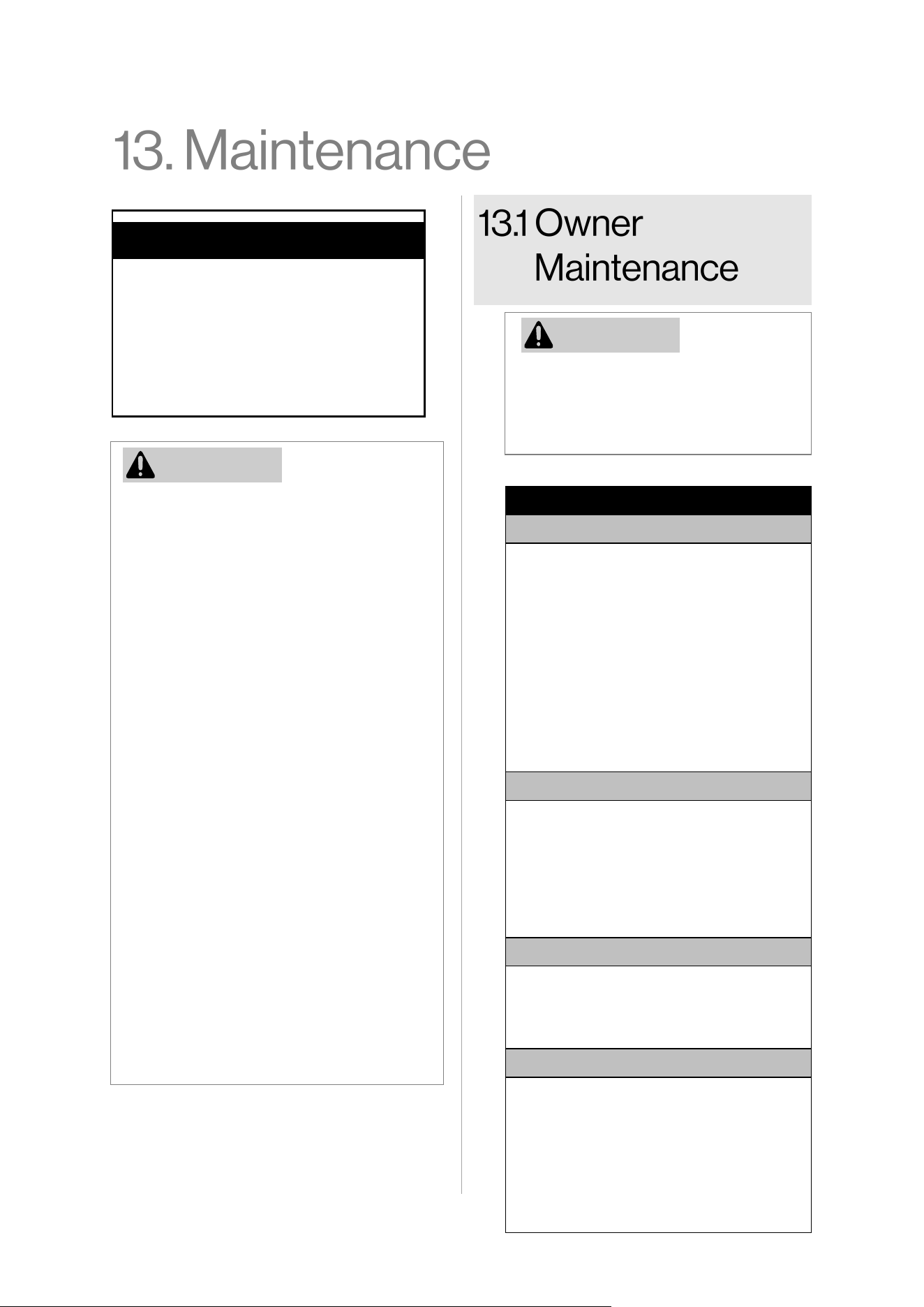
114 Rinnai Commercial Boiler Installation and Operation Manual
• Maintenance is required to maintain
safe operaon of the boiler.
• The boiler must be inspected annually
by a licensed professional. Repairs and
maintenance shall be performed by a
licensed professional. The licensed
professional must verify proper
operaon aer servicing.
• Keep the boiler area clear and free
from combusble materials, gasoline,
and other ammable vapors and
liquids.
• To protect yourself from harm, before
performing maintenance:
− Turn o the electrical power
supply by unplugging the power
cord or by turning o the
electricity at the circuit breaker.
(The boiler controller does not
control the electrical power.)
− Turn o the gas at the manual gas
control valve, usually located
immediately below the boiler.
− Turn o the incoming water
supply. This can be done at the
isolaon valve immediately below
the boiler or by turning o the
water supply to the building.
Topics in this secon
• Owner Maintenance
• Licensed Professional Maintenance
• Service of Heat Exchanger
• Instrucons to Clean Condensate
Trap
• Test the Ignion Safety Shut O
Device
If you encounter a problem that is
dicult to solve, stop the operaon
and immediately contact a licensed
professional.
MONTHLY
Boiler Area
• Verify the area is free of combusble
materials, gasoline and other
ammable vapors and liquids.
• Verify the area is clean from dust and
obstrucons
• Verify the air intake area is free of any
contaminants listed in the boiler
Installaon and Operaon Manual. Any
contaminants in the boiler intake air
vicinity must be removed. If they
cannot be removed, contact a licensed
professional.
Piping
• Inspect all water, gas, and
condensaon piping for leaks. Look for
signs of leaking lines or corrosion.
• Conrm the condensaon line is not
blocked. If a condensaon drain pump
is used, conrm the condensaon drain
pump operates correctly.
Venng
• Verify the boiler vent discharge and air
intake is clean and free of obstrucons.
• Check for leakage, damage, or
deformaon of venng.
Boiler
• Verify the boiler is free from any
abnormal situaons, such as diagnosc
error codes, loud noises, leakage or
other potenal issues.
• Check that the pressure on the
controller display or external pressure
gauge indicates 20-70 psi (138-483
kPa).
WARNING
WARNING
Table 54
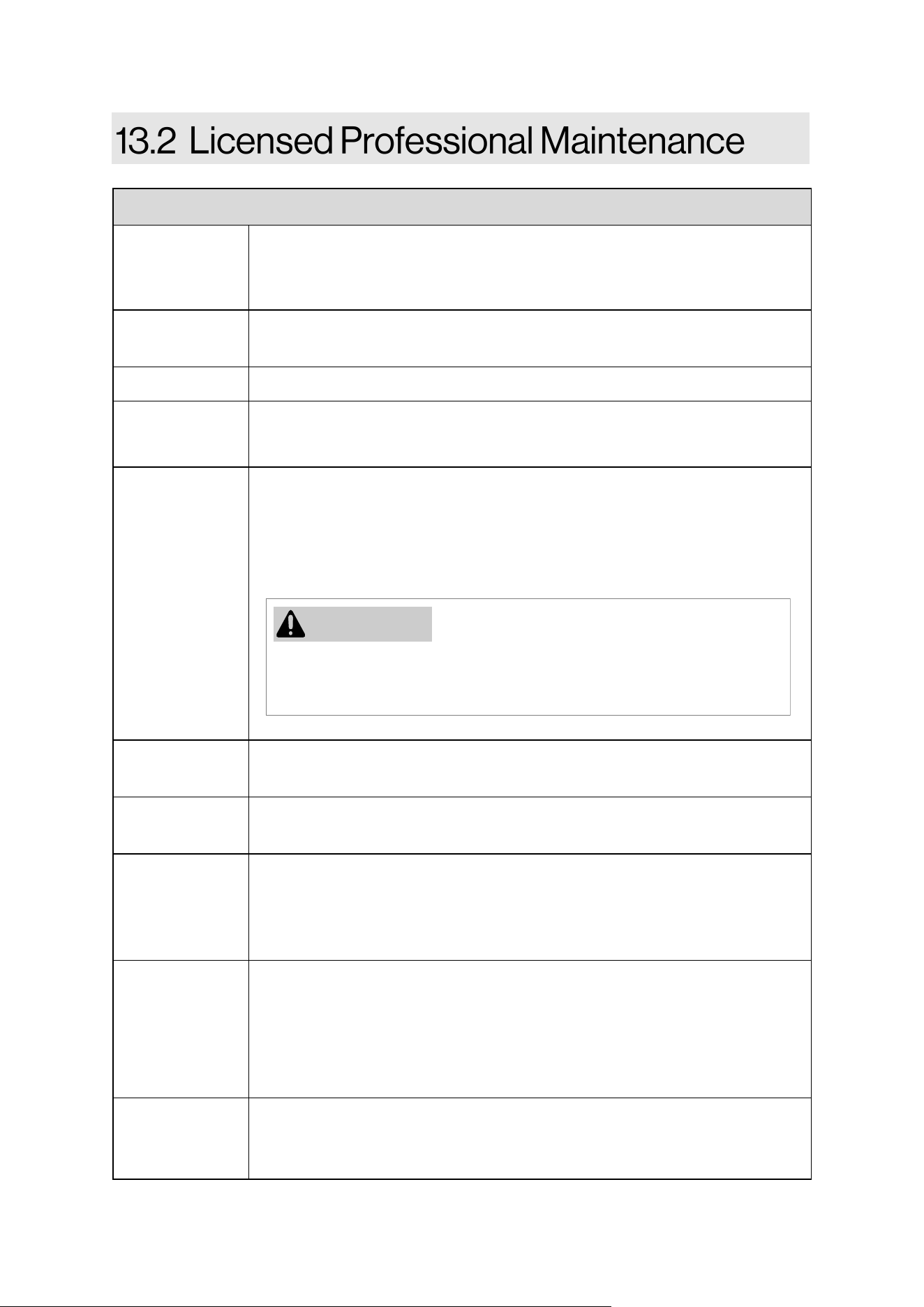
Rinnai Commercial Boiler Installation and Operation Manual 115
ANNUALLY
Vent System • Inspect for blockages or damage.
• Inspect vent screen or room air lter (if using) for debris and blockages.
Clean if needed.
Fan and Motors Clean dust and dirt from fan and motor (motors are permanently lubricated
and do not require lubricaon).
Controller Clean by using a so, damp cloth. Do not use solvents.
Pressure
Conrm the pressure is within the proper range between 20-70 PSI (1.3 -4.8
Bar). If the pressure is lower than the specied range, add water unl in the
proper range.
Pressure Relief
Valve
Check the operaon of pressure relief valve manually once a year. In doing so,
it will be necessary to take precauons with regard to the discharge of
potenally scalding hot water under pressure. Ensure discharge has a safe
place to ow. Contact with your body or other property may cause damage or
harm.
Heang System
Dirt Trap
Clean annually. Be sure to close the shut o valves under the boiler. Aer
cleaning and installing the lter, purge the air.
Expansion Tank Perform annual checks as recommended by the manufacturer to ensure proper
operaon.
Condensaon
Trap
Check if the trap contains sediment. To remove sediment, unplug the boom of
the condensate trap. Remove the sediment, and then return the plug. Do not
use a wrench to ghten the condensate drain as this could cause the
connecon to break.
Condensaon
Drain
• Conrm the condensaon drain line is not blocked or clocked.
• Ensure the condensaon drain pump (if ulized) is working correctly.
• Inspect the condensate neutralizer (if ulized) to ensure the condensate is
draining properly, and there is adequate amount of neutralizing agent
available.
Draining Water When the system will be shutdown for a long period of me (seasonal
shutdown), close the shuto valves below the boiler and drain the boiler to
protect it from potenal freeze damage.
Tesng the pressure relief valve should only be
performed by a licensed professional. Water
discharged from the pressure relief valve could cause severe burns
instantly or death from scalds.
WARNING
Table 55

116 Rinnai Commercial Boiler Installation and Operation Manual
Water Quality Conrm the water quality. Refer to secon “4.3.1 Water Quality Guidelines” to
determine if the water needs to be treated or condioned, and for complete
water quality guidelines. DHW must be potable, free of corrosive chemicals,
sand, dirt, or other contaminates. It is up to the installer to ensure the water
does not contain corrosive chemicals or elements that can aect or damage the
heat exchanger. Water that contains chemicals exceeding the levels required
aect and damage the heat exchanger. Replacement of the heat exchanger due
to water quality damage is not covered by the warranty.
Snow
Accumulaon
• Verify the area around the ue terminal is free of snow and ice. The boiler will
not funcon properly if the combuson air or exhaust vent pipes are impeded
(blocked or parally blocked) by obstrucons.
• Verify the condensate drain line is free of snow and ice. Ensure the line is not
blocked or clogged and that condensate is owing freely.
Freeze
Protecon
• Freeze protecon for new or exisng systems must use glycol that is specially
formulated for this purpose. This includes inhibitors, which prevent the glycol
from aacking the metallic components. The glycol should be for mul-
metallic components. Check that the system uid is correct for the glycol
concentraon and inhibitor level. The system should be tested at least once a
year and as recommended by the producer of the glycol soluon.
Coastal Area
Installaons
Installaons located in or near coastal areas may require addional maintenance
due to corrosive airborne ocean salt. If corrosion is observed on the body of the
boiler, the boiler shall be inspected to ensure proper operaon and repaired or
replaced, if necessary.
Cleaning It is imperave that control compartments, burners, and circulang air
passageways of the boiler be kept clean. Check burner ame for proper color.
Once ignited, the ame must cover the surface of the burner. The ame must
burn with a clear, blue, stable ame. If the ame does not have this appearance,
complete the following steps:
• Turn o and disconnect electrical power. Allow to cool.
• Remove the front panel.
• Use a vacuum to remove dust from the main burner and fan blades. Do not
use a wet cloth or spray cleaners on the burner. Do not use volale
substances such as benzene and thinners; they may ignite or fade the paint.
• Inspect the combuson chamber and clean if needed. Follow the cleaning
procedure listed in this manual.
Condensate Trap Cleaning:
• Inspect the condensate drain assembly inside the boiler and your external
drain system.
• Remove any debris that may be present in the condensate removal system.
Table 55 connue
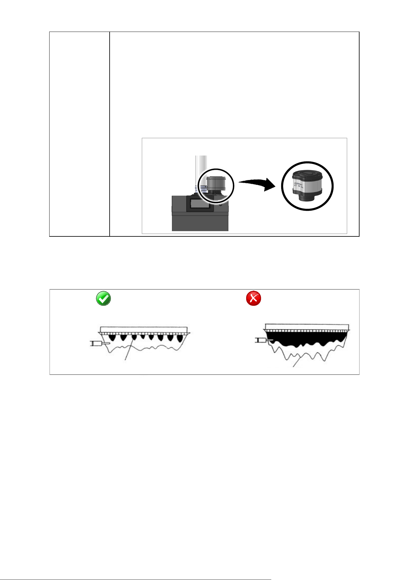
Rinnai Commercial Boiler Installation and Operation Manual 117
Intake Filter
Inspecon:
• To maintain opmum performance, periodically inspect the air lter.
• If the air lter appears to have lint and/or dust build up, follow the
cleaning procedure described below.
• If the air lter appears damaged, contact a trained and qualied
professional for a replacement air lter assembly.
Cleaning:
• Clean the Air Filter: With mild dish soap and a so bristle brush, scrub the
lter area of the air lter door. With clean water, rinse the soap o the
lter.
• Dry the Air Filter: With a lint free towel, dry the air lter.
AFTER SERVICING: VISUAL INSPECTION OF FLAME
Verify proper operaon aer servicing. The burner must ame evenly over the enre surface when
operang correctly. The ame must burn with a clear, blue, stable ame. See the parts breakdown
of the burner for the locaon of the view ports. The ame paern should be as shown in the
images below:
SATISFACTORY
FRONT VIEW
BLUE FLAME
FLAME ROD
YELLOW OR GREEN FLAME
FLAME ROD
UNSATISFACTORY
FRONT VIEW
Freeze Protecon Operaon
The electronic management system of
the boiler includes protecon against frost.
When the boiler detects low outdoor ambient
temperatures, the boiler will begin its freeze
protecon operaon. When freeze protecon is
in operaon, the pump may circulate water
and/or the boiler may re to prevent the boiler
from freezing. Ensure power and gas are
supplied to the boiler for freeze protecon to
funcon. The internal freeze protecon will not
necessarily prevent the system piping from
freezing. If the water temperature falls below
41°F [5°C], the burner starts up and the boiler
pump runs to provide a water temperature of
46°F [8°C] + Boiler Oset 9°F [5°C] + Boiler
Dierenal 20°F [11°C].
Once the target temperature has been
reached the burner will turn o, the boiler
pump will connue to run and turn o aer
post purge period. This funcon only works if
boiler is turned on, the gas supply is ON and
the water pressure is correct. NOTE: The boiler
will not engage in freeze protecon mode if
there are any so or hard lockout error codes.
When the system needs to be
shutdown for extended periods of me, the
power and gas supply should be disconnected
from the boiler. The boiler and all system
piping should then be drained. Freezing
damage may occur if there is water remaining
in the boiler or system piping. The plumbing
lines should also be blown out via compressed
air.
Air Inlet Filter
Figure 63
Figure 62
Table 55 connue
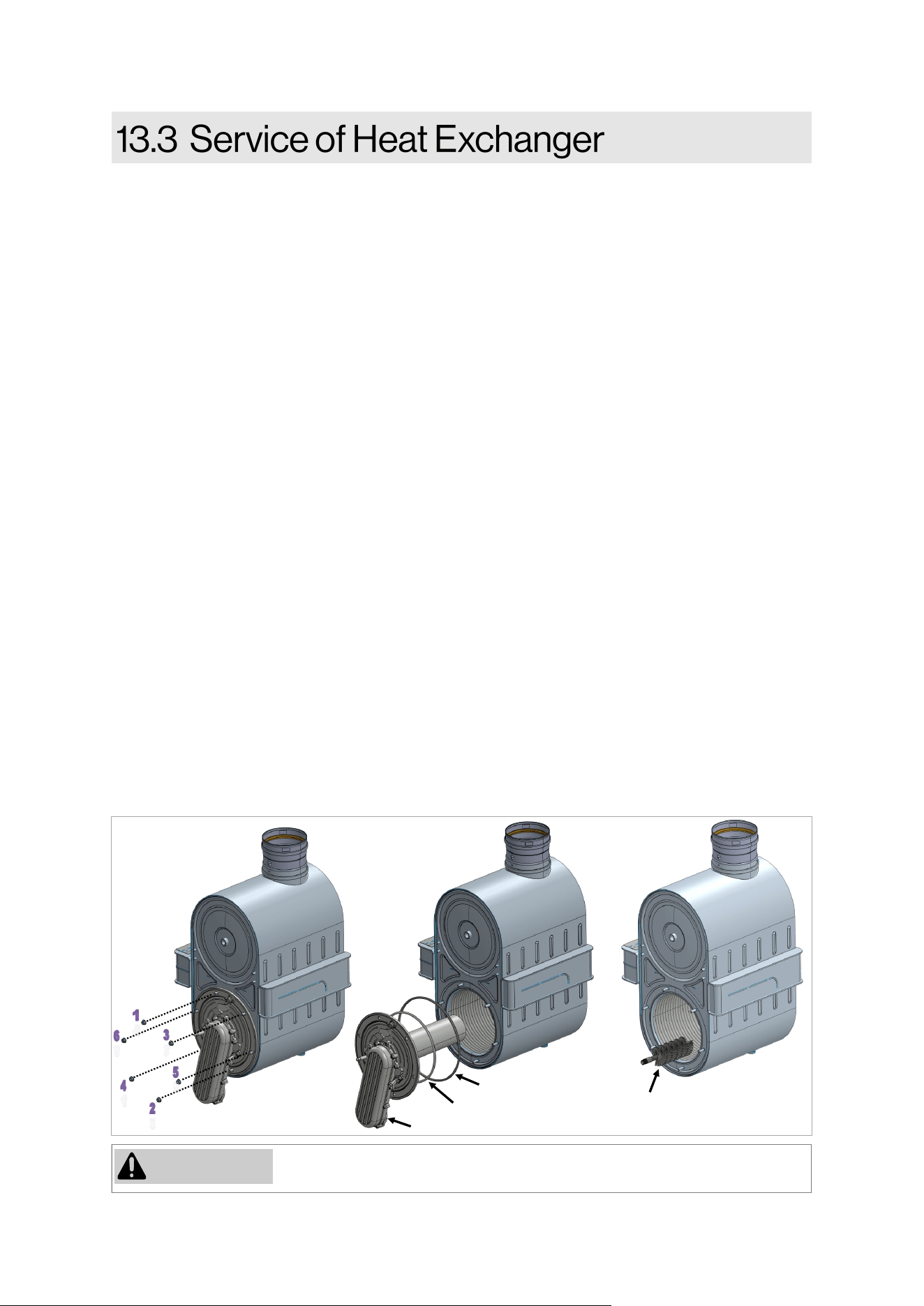
118 Rinnai Commercial Boiler Installation and Operation Manual
If the gaskets are damaged DO NOT reuse, the gaskets must be replaced.
WARNING
Fiber Gasket
Burner Door Gasket
Burner Door
Brush
(Not Provided)
1. Before beginning this procedure, ensure to disconnect the electrical power to the boiler and
close the gas ball valve external to the unit. It is very important to wait for the boiler to cool
down to the touch before connuing with this process.
2. Remove the front panels and visually inspect the water level in the condensate trap to ensure it
is draining properly.
3. Disconnect the wiring connecon from the ignion electrodes, ionizaon probe, and burner
door switch (located on burner door).
4. Disconnect the incoming ex line to the venturi by removing the nut. Detach the fan assembly
from the heat exchanger by removing 4 nuts located towards the back of the unit.
5. Remove the 6 nuts to disassemble the burner door from the heat exchanger (follow the
sequence as shown in the Figure below). Carefully slide out the burner door to clear the studs
on the heat exchanger (pull while rotang to clear any obstrucon and avoid damaging the
components on the burner door assembly).
CLEANING THE HEAT EXCHANGER:
6. Inspect the insulaon disk located on the rear of the combuson chamber. Use a nylon brush
and vacuum to clean combuson residue located inside of the combuson chamber.
NOTE: DO NOT use a metal brush. Using a metal brush will cause irreparable damage to the heat
exchanger.
7. Rinse with clean water. NOTE: Do not rinse the target wall insulaon located on the back of the
combuson chamber. If required spray with white vinegar or a cleaning product suitable for
stainless steel (leave to work for 3 to 5 minutes).
8. Inspect the burner door insulaon disk and gaskets (replace if they are damaged).
9. Check whether the surface of the burner is damaged in any way . Replace burner and its gaskets
if they are damaged. To disassemble the burner, remove 5 screws securing the burner inlet
channel to the burner door. To install new burner, ensure to install it with the burner cap facing
down to ensure the burner ange sits at on the burner door.
Figure 64
RCB500AN
model
shown
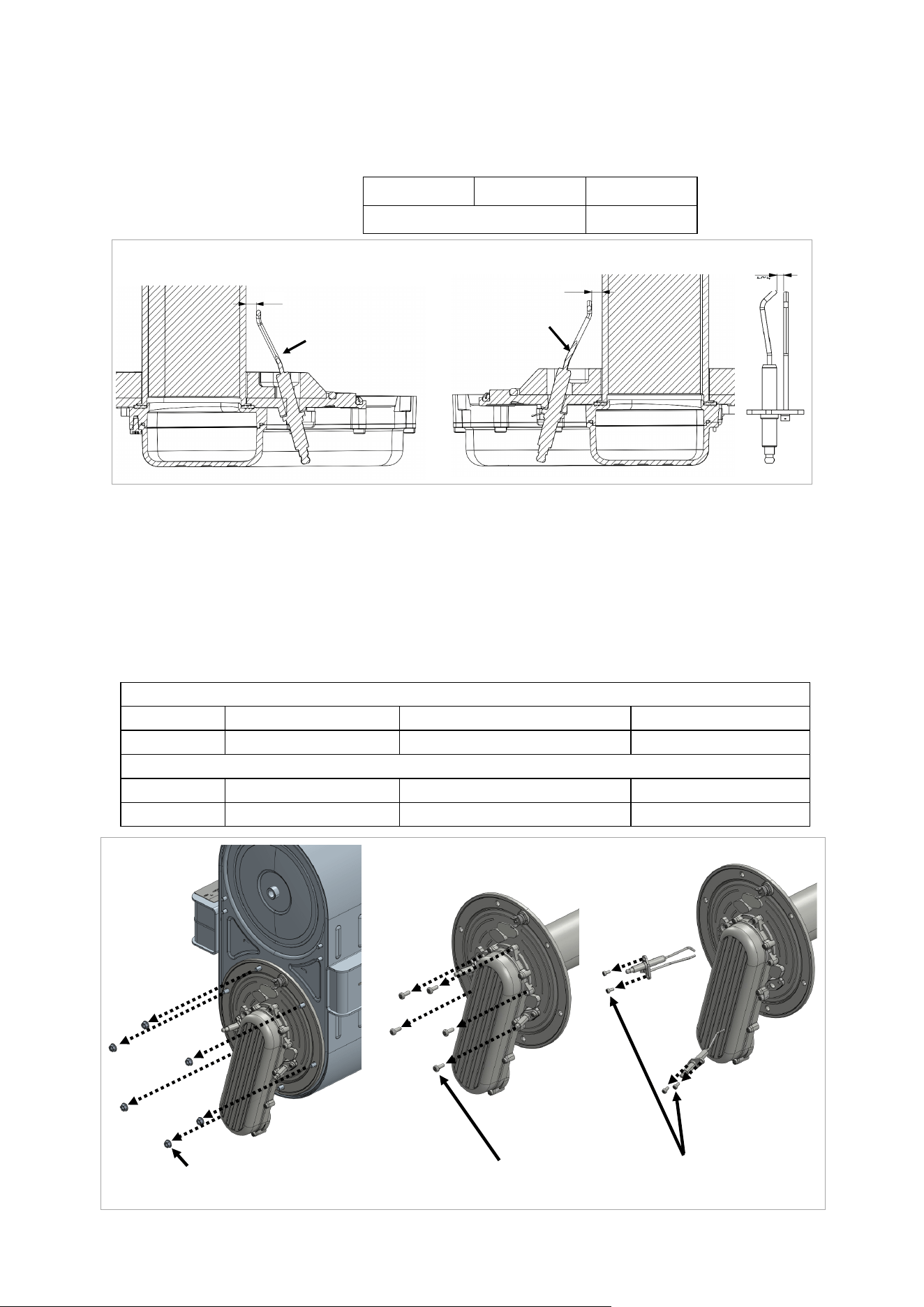
Rinnai Commercial Boiler Installation and Operation Manual 119
Burner
A
Burner
B
C
Ionizaon Probe
Ignion
Electrode
INSPECTING BURNER DOOR ASSEMBLY:
10. Inspect the ignion and ionizaon electrodes. Check the gas of ignion electrodes. Check the
distance from ignion electrode to the burner and check the gap from ionizaon probe to the
burner.
A B C
4.5MM +/- 0.5 10.5MM +/- 1
11. Replace the electrodes if they are damaged or the gap and/or distance to the burner is out of
the specicaons shown in the above table. NOTE: Do not remove the ignion or ionizaon
electrode unless you have spare gaskets and spare parts with gasket available. Most likely the
gasket will get damaged when electrodes are removed.
12. Reassemble the components in the reverse way they were disassembled. NOTE: Ensure to
install the burner door using torque sequence as shown in Figure below. Ensure all gaskets are
in good condion or replace them if necessary. All screws must be ght and torqued according
to the table below.
For Model: RCB500AN
Components Burner Door Nuts (M6) Burner Inlet Chanel Screws (M5) Electrodes Screws (M4)
Torque 44.5 Lb-in (5 Nm) 31 Lb-in (3.5 Nm) 22 Lb-in (2.5 Nm)
For Models: RCB750AN / RCB1000AN
Components Burner Door Nuts (M10) Burner Inlet Chanel Screws (M5) Electrodes Screws (M4)
Torque 442.5 Lb-in (50 Nm) 31 Lb-in (3.5 Nm) 22 Lb-in (2.5 Nm)
Figure 65
Table 57
Table 56
Figure 66
Burner Door
Nuts
Burner Inlet
Chanel Screws
Electrodes
Screws
RCB500AN
model
shown
RCB500AN model shown
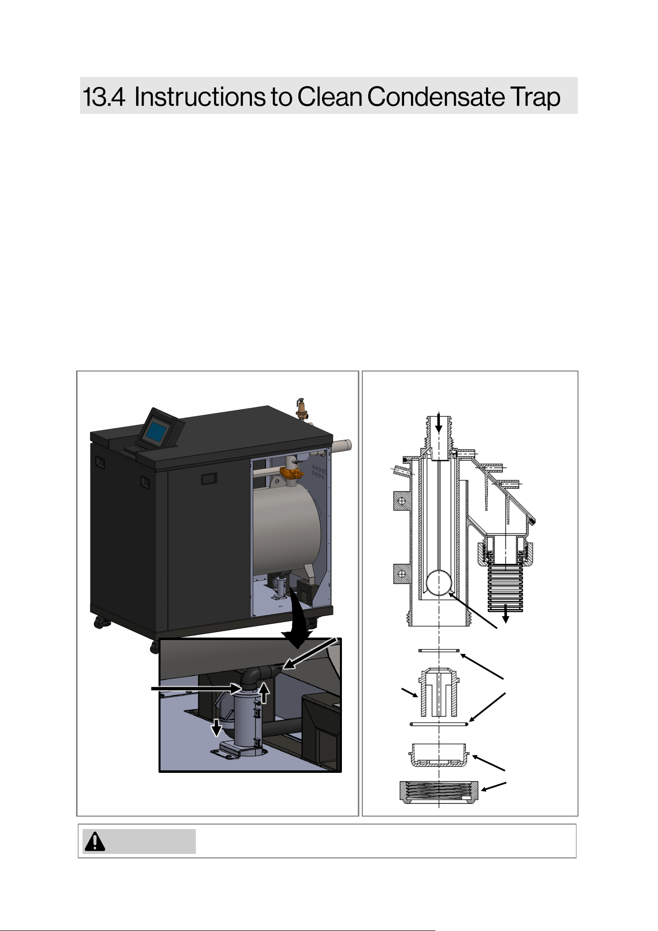
120 Rinnai Commercial Boiler Installation and Operation Manual
If the gaskets/O-rings are damaged DO NOT reuse, they must be replaced.
WARNING
The condensate trap must be lled with water during all mes of boiler operaon to avoid ue gas
emission from the condensate drain line. Failure to ll the trap could result in severe personal
injury or death.
1. Before beginning this procedure, ensure to disconnect the electrical power to the boiler and
close the gas ball valve external to the unit. It is very important to wait for the boiler to cool
down to the touch before connuing with this process.
2. Remove the boiler front panel and locate the condensate trap.
3. Loosen the clamp and remove the hose connected to the inlet of the condensate trap.
Disconnect the clear hose from the APS connected on the side of the condensate trap inlet
connecon.
4. Loosen the nut on the discharge of the condensate trap. NOTE: Inspect the gasket and replace
if needed.
5. Remove the condensate trap assembly for inspecon. Remove the cap located on the boom
of the condensate trap and clean with fresh water. Inspect the oang ball and O-rings located
inside of the condensate trap and ensure the ball is oang freely.
Floang ball (acts
as a check valve)
O-ring
Cap
Stopper
INLET
OUTLET
Figure 67
Figure 68
Clamp
Clamp
RCB1000AN model shown
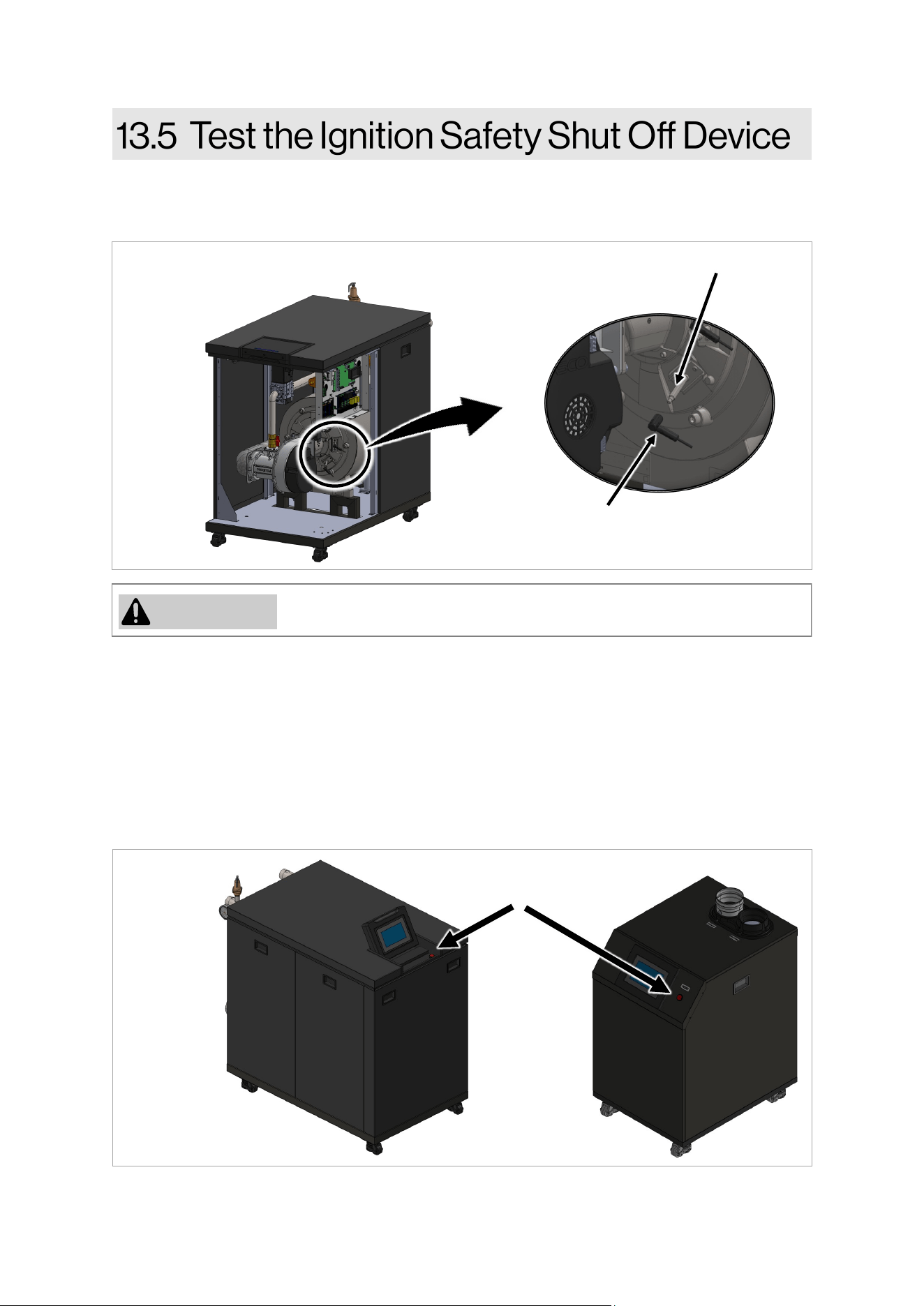
Rinnai Commercial Boiler Installation and Operation Manual 121
4. Place the boiler in operaon by a call for heat (using room thermostat or from service page).
5. The boiler iniates one start-up aempt followed by three restart aempts.
Aer the last start-up aempt, the boiler locks out and the gas valve shuts o. Code ‘133 Safety
me for establishment of ame’ appears on the controller display which indicates ignion
system safety shuto.
6. Reconnect the wiring connecon to the ame rod. Be careful not to touch the inside of the
wiring connecon. To reset the error, press the reset buon located on the right side of the
display panel on 500 model, and under the display panel assembly for 750 and 1000 models .
The boiler starts up.
1. Remove the boiler front panel.
2. Ensure the boiler is not currently ring and the ame rod is not hot to touch.
3. Disconnect the wiring connecon from the ame rod (located on burner door—lower side)
7. Replace the boiler front panel.
8. The boiler may now go back into normal operaon.
Do not touch the inside of the wiring connecon while it is disconnected.
WARNING
Figure 70
Figure 69
Flame Rod
Flame Rod
Plug
Reset Buon
RCB1000AN model shown
122 Rinnai Commercial Boiler Installation and Operation Manual
When replacing an exisng boiler, the
heang system shall be ushed with an
approved system cleaner before the new
boiler is added to the system.
The Rinnai boiler must be isolated from the
system while the system is ushed. No
system cleaner should ever enter the boiler
heat exchanger due to its causc nature
which could damage the heat exchanger.
Instrucons
1. Flush the CH system with water.
2. Isolate the boiler from the CH system.
3. Fill the CH system with an approved
cleaner and circulate through the system.
4. If the installaon is a zone system (ulizes
mulple zones), ush out each zone
individually.
5. Flush the CH system with water again,
ensuring all zones have been ushed.
6. Clean out the dirt trap per manufacture’s
instrucons.
7. The boiler and system may now be lled
through the ll valves.
8. If using glycol, ensure it is an approved
glycol and rao.
9. Verify water quality is within the stated
values in secon “4.3.1 Water Quality
Guidelines.”
IMPORTANT
• Water should be within guidelines for
water quality listed in secon “4.3.1
Water Quality Guidelines.”
• Use the proper water treatment to
ensure the pH and water hardness are
within the Rinnai boiler water quality
guidelines listed in secon “4.3.1 Water
Quality Guidelines.”
• Test the pH of the water that will be
used for lling the system.
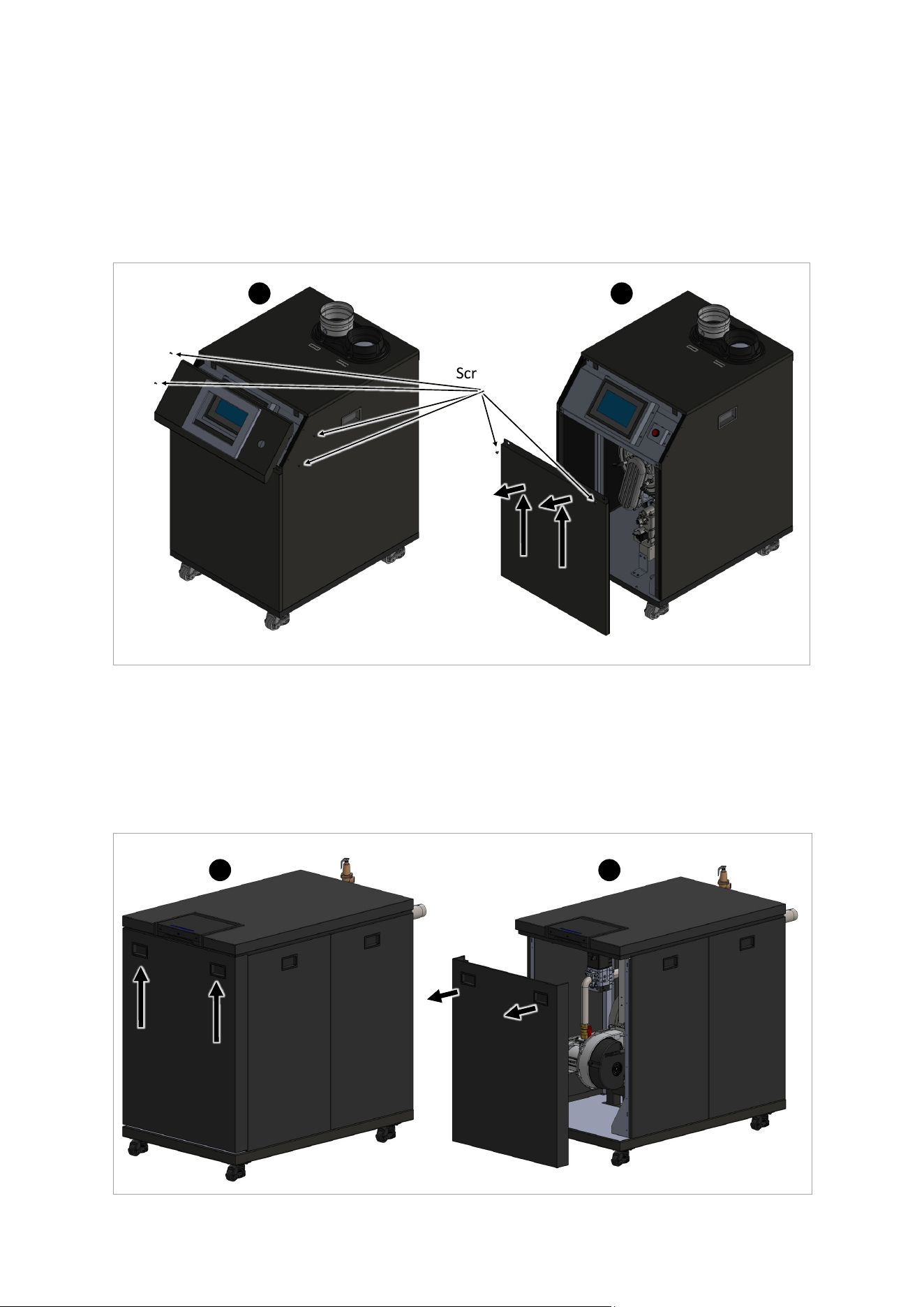
Rinnai Commercial Boiler Installation and Operation Manual 123
Front Panel Removal Instrucons (750 & 1000 Models):
1. Use two handles to move up to front panel in order for the hooks to clear the slots holding the
front panel in place (A in Figure 72).
2. Pull the panel out and remove it from the boiler (B in Figure 72).
3. Place the removed front panel at a safe locaon unl it can be remounted aer the service.
A B
Figure 72
Front Panel Removal Instrucons (500 Model):
1. Use a Phillips head screwdriver to remove four (4) screws securing the angle panel around the
display assembly (A in Figure 71). Place it is safe locaon unl it is needed for re-assembly.
2. Use a Phillips head screwdriver to remove two screws securing the front panel (B in Figure 71).
Slide the panel up to clear the pins on the boom, then pull it out to remove it from the boiler.
3. Place the removed front panel at a safe locaon unl it can be remounted aer the service.
A B
Screws
Figure 71
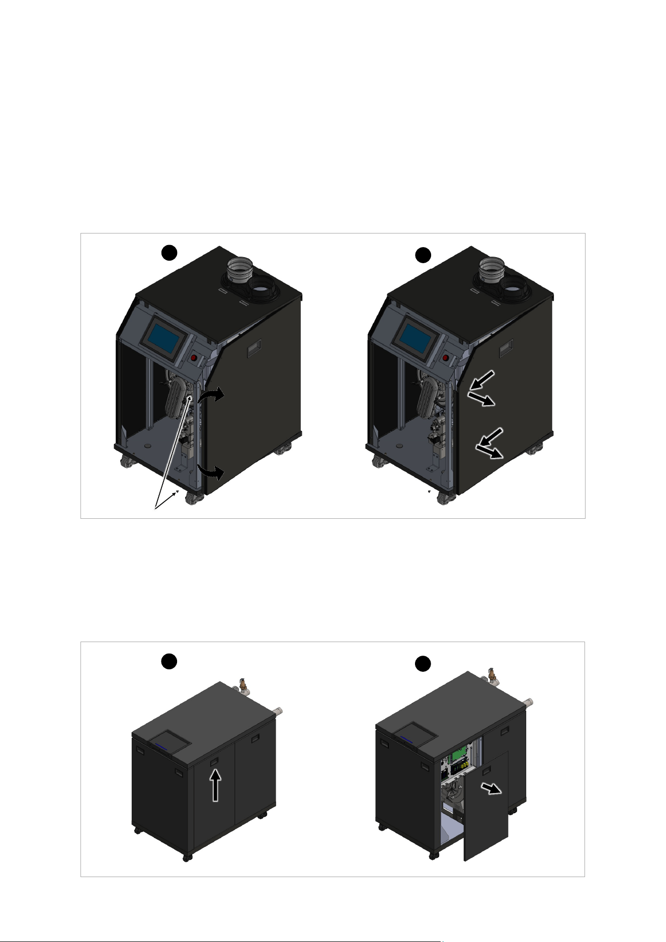
124 Rinnai Commercial Boiler Installation and Operation Manual
Side Panel Removal Instrucons (500 Model):
1. Remove the front panel as shown in front panel removal instrucons. Place the front panel on
a safe place where it can not be damaged.
2. Remove two screws for each panel from the front of the boiler, then rotate the side panel out
to clear the boom part of the side panel (A in Figure 73).
3. Pull the panel forward to clear the locking mechanism on the back side then pull the panel out
(B in Figure 73).
4. Place the removed side panel at a safe locaon unl it can be remounted aer the service.
Screws
Figure 73
B
A
Side Panel Removal Instrucons (750 and 1000 Models):
1. Use two handles to move up to front panel in order for the hooks to clear the slots holding the
front panel in place (A in Figure 74).
2. Pull the panel out and remove it from the boiler (B in Figure 74).
3. Place the removed side panel at a safe locaon unl it can be remounted aer the service.
Figure 74
B
A
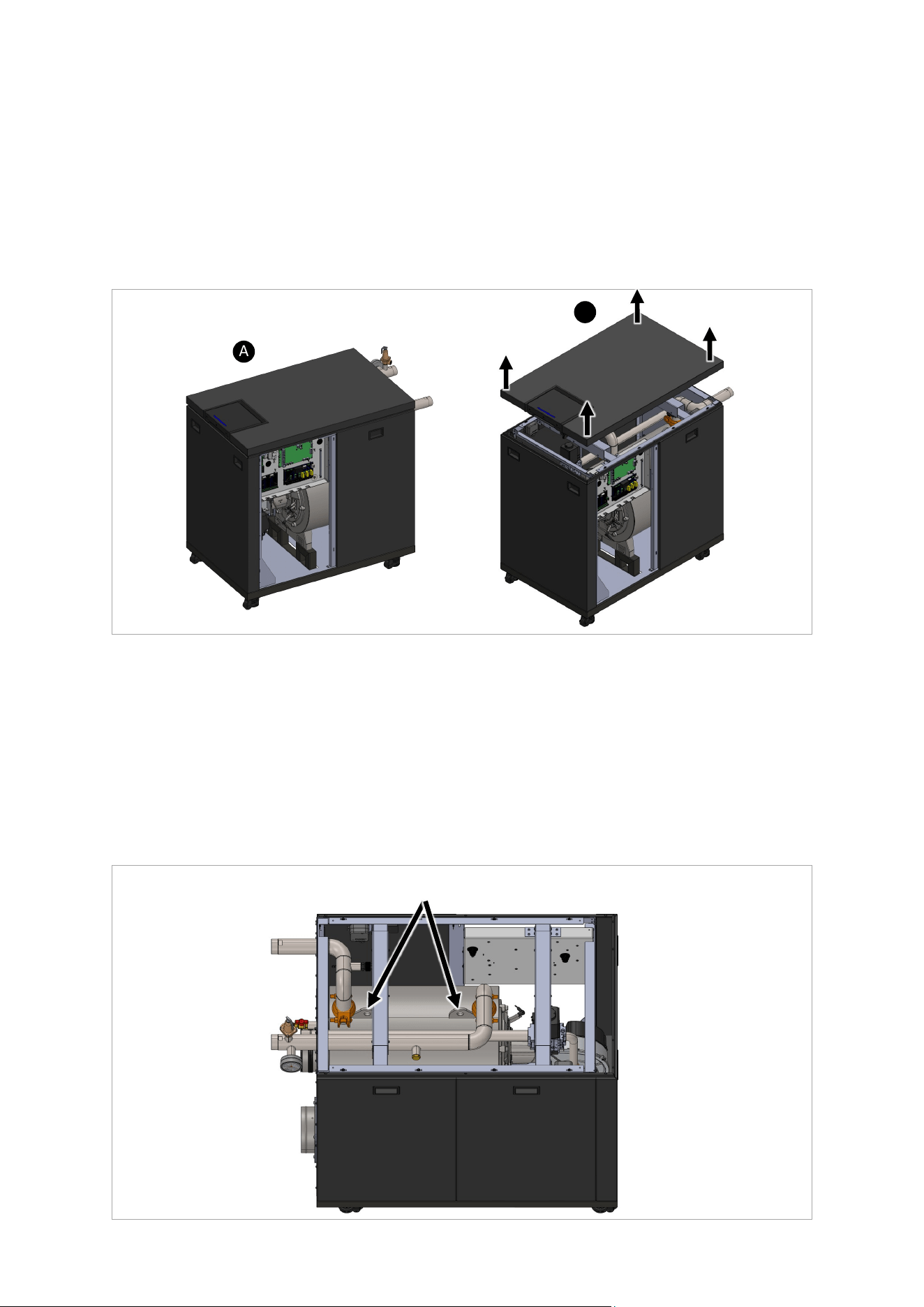
Rinnai Commercial Boiler Installation and Operation Manual 125
Top Panel Removal Instrucons (750 and 1000 Models):
1. Remove the front le side panel to gain access to the electrical connecons.
2. Disconnect the display LAN cable from the high voltage connecon board, remove the quick
disconnects for reset buon cable and LED indicator cable.
3. The top panel assembly (with display) is secured in place with 6 locking pins. Pull up the top
panel from the four corners to disconnect it from the boiler.
4. Place the removed top panel at a safe locaon unl it can be remounted aer the service.
Figure 75
B
A
Figure 76
Boiler Liing Instrucons (750 and 1000 Models):
Due to heavy weight, it might be dicult to move the appliance to certain locaon. The appliance
has built-in casters that facilitates to move them around on at surfaces. Also the unit can be
picked up using pallet jack or forkli if needed. In some circumstances the unit might need to be
lied to go through an area with limited access. In this case, follow the steps below:
1. Follow the above instrucon to remove the top panel assembly (Figure 75).
2. Use the provided liing lugs on the heat exchanger to li the boiler (Figure 76).
Place the removed side panel at a safe locaon unl it can be remounted aer the service.
Liing Lugs
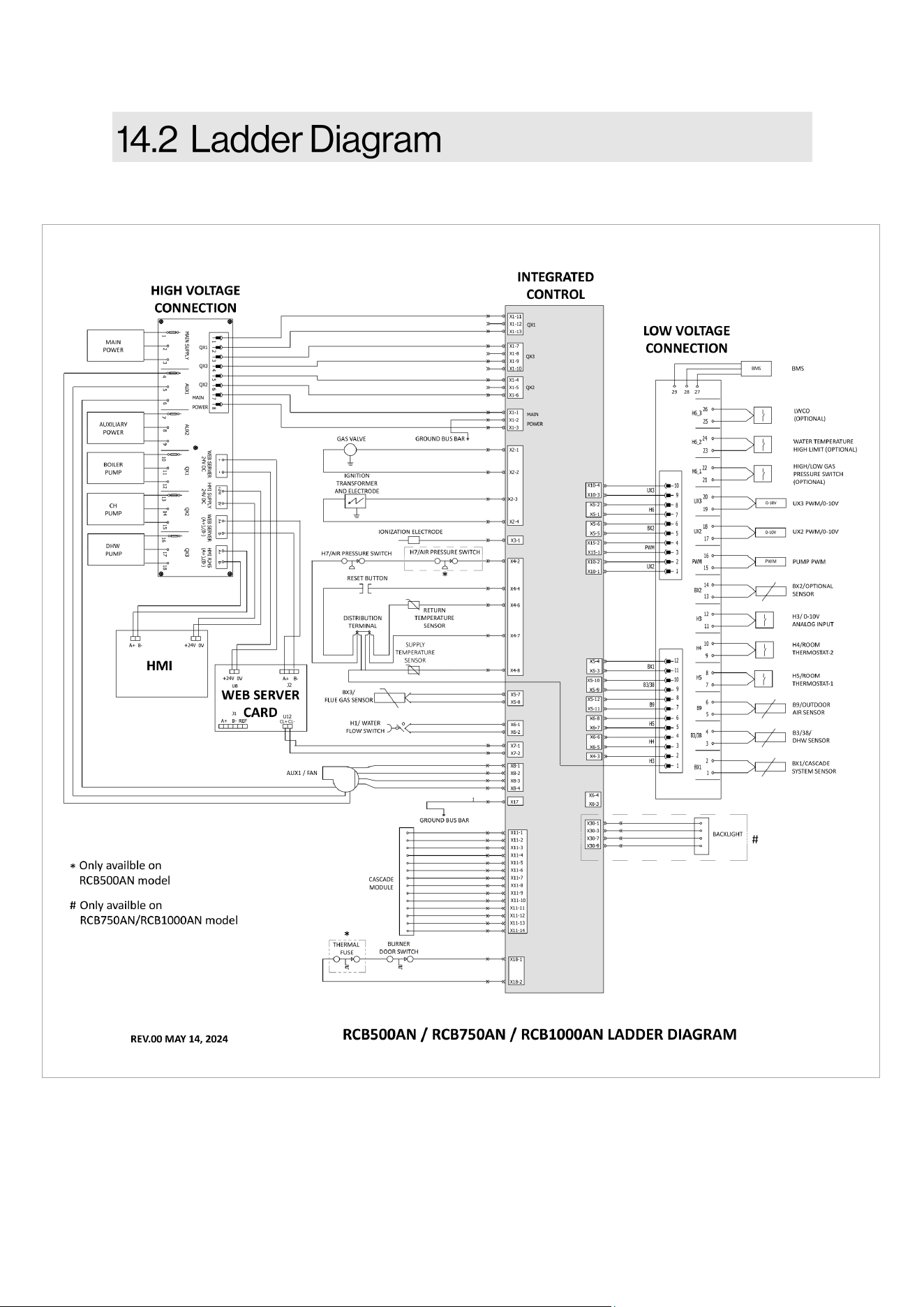
126 Rinnai Commercial Boiler Installation and Operation Manual
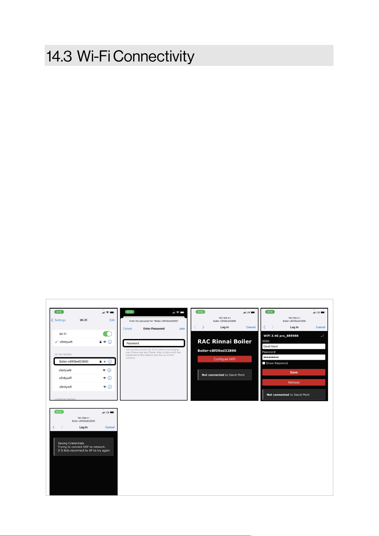
Rinnai Commercial Boiler Installation and Operation Manual 127
The Rinnai Commercial Boiler is shipped out of the factory with built-in Wi-Fi. In order to connect
the unit to Wi-Fi follow the steps below:
1. Access the boiler SETUP page under Wi-Fi sub-menu to enable Wi-Fi.
2. Use a smart phone, tablet, or computer with Wi-Fi access and search for the device, the
name should be Boiler - xxxxxxxxxxxx (Figure A). The digits in front of the boiler represent
the boiler MAC ID. If there are mulple devices in the same boiler room, check for the
correct MAC ID of the device being connected from the VIEW page sub-menu info. NOTE:
If the device was previously connected to Wi-Fi and new connecon is being established,
press forget Wi-Fi icon on the boiler SETUP page under Wi-Fi submenu to forget previous
connecon.
3. On the Wi-Fi list, click on Boiler - xxxxxxxxxxxx to connect to the device. A new screen will
pop-up and prompt for a password. The password is 123456789. Enter the password then
click Join to connect to the device (Figure B).
4. Once the credenals are veried, the screen will disappear and new window will pop-up to
congure Wi-Fi. In case this window does not show up automacally, go to internet
browser and type the following address: 192.168.4.1 (Figure C).
5. Click on congure Wi-Fi window to enter Wi-Fi credenals for the network intended for
this connecon (Figure D).
6. New screen will pop-up while the credenals are being saved and veried. Once the
connecon has been established the screen will disappear.
7. Verify on the boiler home page (top right corner) for connecvity.
8. Follow next steps on Rinnai Central app to add the device to the user account.
Figure A Figure B Figure D
Figure E
Figure C
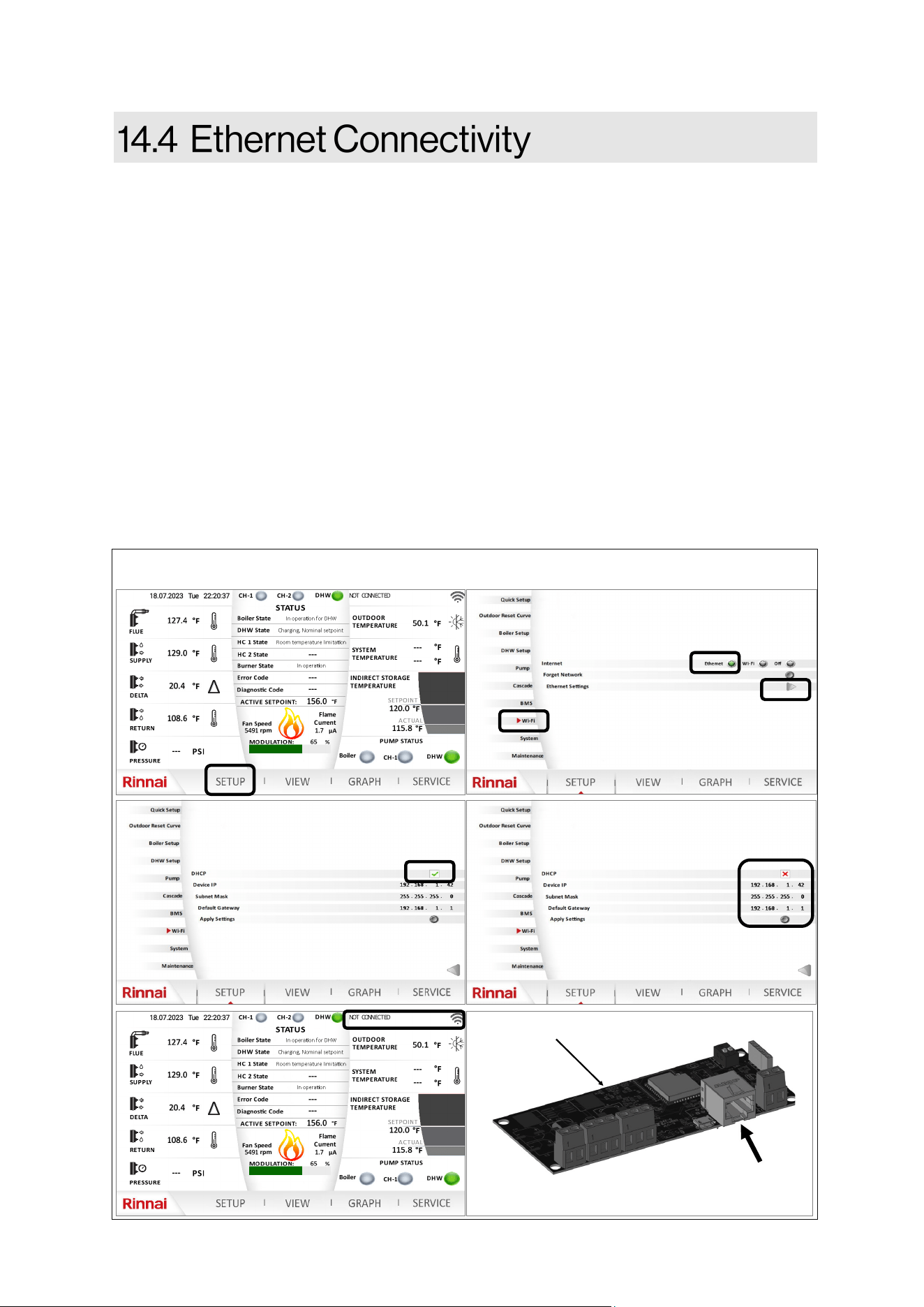
128 Rinnai Commercial Boiler Installation and Operation Manual
The Rinnai Commercial Boiler is shipped out of the factory with built-in Wi-Fi. If Wi-Fi signal is not
available at the installaon site or if the signal is poor, the boiler can be hardwired and connected
via an ethernet port. Follow the steps below:
1. Connect a LAN cable (CAT 5 or CAT 6) from the Webserver Card to the Network device.
2. From the Home screen, click on SETUP and select the appropriate user and enter the
password to gain access to SETUP page.
3. Once in the SETUP page, click on Wi-Fi submenu on the le.
4. Select Ethernet opon (default is O).
5. Once Ethernet opon is selected, then click on the arrow for Ethernet Sengs .
6. If DHCP is enable on the network (it varies from site to site - user preference), then click on
the DHCP icon to enable DHCP. The unit should connect to the network. Verify on the Wi-Fi
home page for connecvity.
7. If DHCP is disabled. Disable the DHCP on the Wi-Fi screen , under Ethernet Sengs.
8. Enter the Device IP, Subnet Mask, and Default Gateway into the related led on the
screen. Once the process is completed, click on Apply Sengs to save the conguraon.
Verify on the Wi-Fi home page for connecvity.
Figure 77
Ethernet connecon
port
Webserver Card
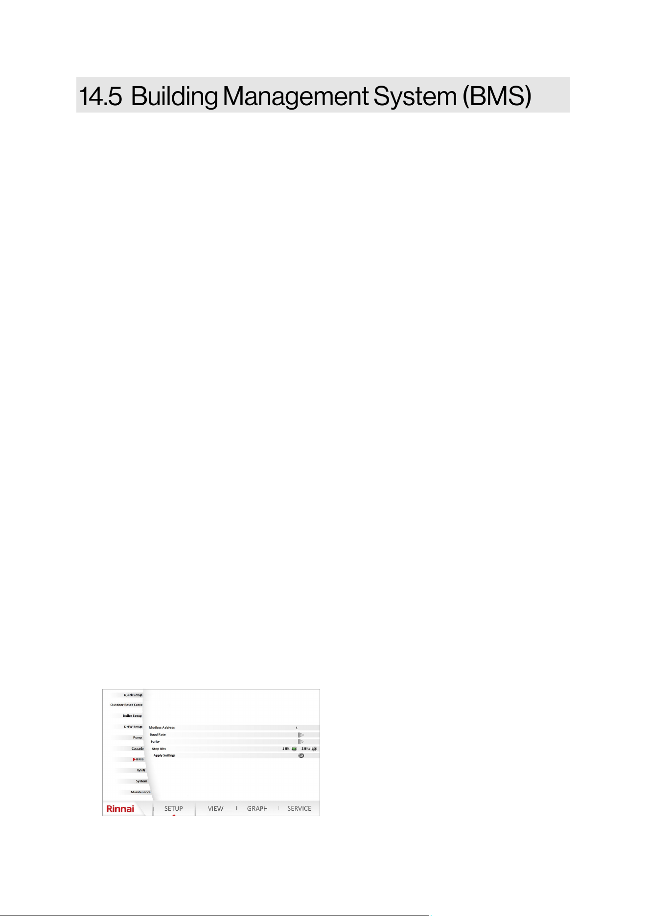
Rinnai Commercial Boiler Installation and Operation Manual 129
This secon of the manual provides guidelines for the use of Modbus communicaon system with
Rinnai Commercial Boiler (RCB) appliances.
1. Disconnect the electrical power before beginning the process. Failure to do so could result
in electrical shock, property/appliance damage, serious personal injury , or death.
2. Ensure to have a Modbus master device such as a Building Management System (BMS) or a
computer with Modbus master soware, and an RS-485 serial port or USB port with a
converter to RS-485.
3. Wire the BMS to the Modbus connecons on the low voltage terminals labeled BMS
(A+; B- ; REF).
4. On the boiler screen enter the SETUP page and click on BMS to access the Modbus
conguraon.
Modbus Address:
Addresses 1 - 20 (Default: 1) are free to be assigned to Modbus devices on the bus. Each
address can be assigned to ONLY one Modbus device on the bus.
Baud Rate:
All devices must have the same baud rate. The baud rate (communicaon speed) can be set on
the control display to 4800, 9600, 19200, 38400 or default (115200) baud. The higher the value
the higher is the speed, but less number of devices can be connected and the cable length gets
shorter. This boiler, as well as any other device on the same bus and the Modbus master, must
have the same baud rate seng. Select the highest baud rate that oers the most reliable
communicaon performance over the bus. Some things that can aect communicaons are:
Long wire runs; Wire quality; A noisy electrical environment; The number of devices on the
bus. These condions may require using a lower baud rate.
Parity & Stop Bits:
All devices must have the same parity and stop bits. The parity & stop bits parameters of the
Modbus must be set to match the rest of the devices on the bus. Although it is common to set
serial devices to use no parity, seng the parity to even or odd may improve communicaons
reliability on all connected devices on the bus. This parameter has 6 possible selecons which
should be sucient to establish communicaon with other devices (Parity none - 1 stop bits;
Parity none - 2 stop bits; Parity eve - 1 stop bits; Parity even - 2 stop bits; Parity odd - 1 stop
bits; Parity odd - 2 stop bits).
Apply Sengs:
Click on apply sengs buon to save parameters aer adjustments.
130 Rinnai Commercial Boiler Installation and Operation Manual
MODBUS LIST
MODBUS
REGISTER
POINT NAME POINT
RESOLUTION
RELATED LINE
NUMBER
READ (R) or
WRITE (W)
UNIT
600 FLUE TEMPERATURE x10 8316 R °C | °F
601 SUPPLY TEMPERATURE x10 8310 R °C | °F
602 RETURN TEMPERATURE x10 8314 R °C | °F
603 WATER PRESSURE x10 9005 R BAR | PSI
604 BOILER SETPOINT x10 8311 R °C | °F
605 ERROR CODE - 6700 R -
606 DIAGNOSTIC CODE - 6705 R -
607 FLAME CURRENT x10 8329 R µA
608 CURRENT FAN SPEED - 8323 R RPM
609 OUTDOOR TEMPERATURE x10 8700 R °C | °F
610
SYSTEM TEMPERATURE
ACTUAL
x10 8318 R °C | °F
611
SYSTEM TEMPERATURE
SETPOINT
x10 8319 R °C | °F
612 DHW TEMPERATURE ACTUAL x10 8830 R °C | °F
613 DHW TEMPERATURE SETPOINT x10 1610 R °C | °F
614 BOILER STATE - 8005 R -
615 DHW STATE - 8003 R -
616 HC1 STATE - 8000 R -
617 HC2 STATE - 8001 R -
618 BURNER STATE - 8009 R -
619 MODULATION - 8326 R %
620 MINIMUM FAN SPEED LF - 9524 R rpm
621 MAXIMUM FAN SPEED HF - 9529 R rpm
622 IGNITION FAN SPEED - 9512 R rpm
623 FAN SETPOINT - 8324 R. rpm
624 CURRENT FAN CONTROL - 8325 R %
625 ROOM THERMOSTAT CH1 - 7865 R -
626 ROOM THERMOSTAT CH2 - 7860 R -
627
THERMOSTAT STATE CH1
DEMAND
- 8749 R -
628
THERMOSTAT STATE CH2
DEMAND
- 8779 R -
629 0-10V INPUT H3 x10 7854 R V
630 WATER PRESSURE SENSOR H1 - 7841 R -
631 WATER PRESSURE VOLTAGE x10 7840 R V
632 AIR PRESSURE SWITCH H7 - 7874 R -
633 GAS PRESSURE SWITCH H6 - 7872 R -
634 BURNER RUN HOURS - 8330 R h
Table 58
Rinnai Commercial Boiler Installation and Operation Manual 131
MODBUS LIST
MODBUS
REGISTER
POINT NAME POINT
RESOLUTION
RELATED LINE
NUMBER
READ (R) or
WRITE (W)
UNIT
635 IGNITION CYCLES - 8331 R -
636 RUN HOURS HEATING - 8338 R h
637 RUN HOURS DHW - 8339 R h
638 TOTAL GAS ENERGY HC - 8378 R kWh
639 TOTAL GAS ENERGY DHW - 8379 R kWh
640 TOTAL GAS ENERGY CH & DHW - 8380 R kWh
641 GAS ENERGY FOR CH - 8381 R kWh
642 GAS ENERGY FOR DHW - 8382 R kWh
643 GAS ENERGY FOR CH & DHW - 8383 R kWh
644 BOILER PUMP Q1 - 8031 R -
645 BOILER PUMP Q1 SPEED - 8308 R %
646 CH PUMP Q2 - 9032 R -
647 DHW PUMP Q3 - 9033 R -
648 DHW PUMP Q3 SPEED - 8825 R %
649 UX2 - 7717 / 7719 R V | %
650 UX3 - 7725 / 7726 R V | %
651 P1 - 7714 R %
652 CASCADE MASTER INFO - 8101 R -
653 CASCADE FOLLOWER 1 INFO - 8103 R -
654 CASCADE FOLLOWER 2 INFO - 8105 R -
655 CASCADE FOLLOWER 3 INFO - 8107 R -
656 CASCADE FOLLOWER 4 INFO - 8109 R -
657 CASCADE FOLLOWER 5 INFO - 8111 R -
658 CASCADE FOLLOWER 6 INFO - 8113 R -
659 CASCADE FOLLOWER 7 INFO - 8115 R -
660 WEB SERVER CARD VERSION x1000 - R -
661 LMS PARAMETER VERSION 1 - 6230 R -
662 LMS PARAMETER VERSION 2 - 6231 R -
663 IMPERIAL/METRIC SELECTION 0-1 - R -
NOTE: For the switches state: 0 - Open ; 1 - Closed
Table 58 connue
132 Rinnai Commercial Boiler Installation and Operation Manual
The following informaon is required by ANSI Z21.13:
NOTE: Not all statements are applicable to this appliance.
If a boiler is removed from a common vent system, the common vent system is likely to be too large
for proper venng of the remaining appliances connected to it.
The instrucons shall include the test procedure set forth below:
At the me of removal of an exisng boiler, the following steps shall be followed with each other
appliances remaining connected to the common venng system are not in operaon.
1. Seal any unused openings in the common venng system.
2. Visually inspect the venng system for proper size and horizontal pitch and determine
there is no blockage or restricon, leakage, corrosion and other deciencies which could
cause an unsafe condion.
3. Insofar as is praccal, close all building doors and windows and all doors between the
space in which the appliances remaining connected to the common venng system are
located and other spaces of the building. Turn on clothes dryers and any appliance not
connected to the common venng system. Turn on any exhaust fans, such as range hoods
and bathroom exhausts, so they will operate at maximum speed. Do not operate a
summer exhaust fan. Close replace dampers.
4. Place in operaon the appliance being inspected. Follow the lighng instrucons. Adjust
thermostat so appliance will operate connuously.
5. Aer it has been determined that each appliance remaining connected to the common
venng system properly vents when tested as outlined above, return doors, windows,
exhaust fans, replace dampers, and any other gas-burning appliance to their previous
condion of use.
6. Any improper operaon of the common venng system should be corrected so the
installaon conforms with the Naonal Fuel Gas Code, ANSI Z223.1/NFPA 54, and/or the
Natural Gas and Propane Installaon Code, CAN/CSA B149.1. When resizing any poron of
the common venng system, the common venng system should be resized to approach
the minimum size as determined using the appropriate tables in Chapter 13 of the
Naonal Fuel Gas Code, ANSI Z223.1/NFPA 54, and/or the Natural Gas and Propane
Installaon Code, CAN/CSA B149.1.

Rinnai Commercial Boiler Installation and Operation Manual 133
FOR GAS MODELS SOLD IN MASSACHUSETTS
NOTICE BEFORE INSTALLATION:
This direct-vent appliance must be installed by a properly trained licensed professional. If you are
not properly trained, you must not install this unit.
IMPORTANT: In the State of Massachuses (248 CMR 4.00 & 5.00):
For all side wall horizontally vented gas fueled equipment installed in every dwelling, building or
structure used in whole or in part for residenal purposes, including those owned or operated by
the Commonwealth and where the side wall exhaust vent terminaon is less than 7 above
nished grade in the area of the venng, including but not limited to decks and porches, the
following requirements shall be sased:
1. INSTALLATION OF CARBON MONOXIDE DETECTORS. At the me of installaon of the side wall
horizontal vented gas fueled equipment, the installing plumber or gaser shall observe that a
hard wired carbon monoxide detector with an alarm and baery back-up is installed on the
oor level where the gas equipment is to be installed. In addion, the installing plumber or
gaser shall observe that a baery operated or hard wired carbon monoxide detector with an
alarm is installed on each addional level of the dwelling, building or structure served by the
side wall horizontal vented gas fueled equipment. It shall be the responsibility of the property
owner to secure the services of qualied licensed professionals for the installaon of hard
wired carbon monoxide detectors
A In the event that the side wall horizontally vented gas fueled equipment is installed in a
crawl space or an ac, the hard wired carbon monoxide detector with alarm and baery
back-up may be installed on the next adjacent oor level.
B In the event that the requirements of this subdivision can not be met at the me of
compleon of installaon, the owner shall have a period of thirty (30) days to comply with
the above requirements; provided, however, that during said thirty (30) day period, a
baery operated carbon monoxide detector with an alarm shall be installed.
2. APPROVED CARBON MONOXIDE DETECTORS. Each carbon monoxide detector as required in
accordance with the above provisions shall comply with NFPA 720 and be ANSI/UL 2034 listed
and IAS cered.
3. SIGNAGE. A metal or plasc idencaon plate shall be permanently mounted to the exterior
of the building at a minimum height of 8 above grade directly in line with the exhaust vent
terminal for the horizontally vented gas fueled heang appliance or equipment. The sign shall
read, in print size no less than one-half (1/2) inch in size, "GAS VENT DIRECTLY BELOW. KEEP
CLEAR OF ALL OBSTRUCTIONS.”
4. INSPECTION. The state or local gas inspector of the side wall horizontally vented gas fueled
equipment shall not approve the installaon unless, upon inspecon, the inspector observes
carbon monoxide detectors and signage installed in accordance with the provisions of 248 CMR
5.08(2)(a)1 through 4.
134 Rinnai Commercial Boiler Installation and Operation Manual
Models: RCB500AN, RCB750AN, and RCB1000AN
What Is Covered?
The Rinnai Standard Limited Warranty covers any defects in materials or workmanship when the
product is installed and operated according to Rinnai published product specicaons, subject to
the terms within this Limited Warranty document. This Limited Warranty applies only to products
that meet the requirements of a “qualied product installaon” and are originally installed in the
United States and Canada. Improper installaon may void this Limited Warranty. A “qualied
product installaon” consists of the following: (1) installed by a company or individual which (a)
holds a current government issued license which ceres the company or individual is qualied to
install and service commercial gas boilers in the state where the product is located, if such licensing
is required; and, (b) has successfully completed Rinnai commercial gas boiler product training at an
approved Rinnai training facility and/or by a remote training program Rinnai authorized trainer, and
(2) installaon, startup, operaon and service is performed in compliance with (a) all Rinnai
published engineering, applicaon, installaon, startup and service documentaon, (b) all
applicable federal, state and local laws, (c) applicable plumbing, electrical, mechanical and building
codes and best industry standards. This Limited Warranty is subject to the condions that the
Rinnai boiler has been installed per the “qualied product installaon” terms and ongoing and
proper maintenance has been performed, according to Rinnai Installaon and Service
documentaon, by a professional, licensed (if required) heang contractor. Proof of the required
service and maintenance tasks being completed must be kept in the provided Rinnai Installaon,
Commissioning and Service Record. This Limited Warranty coverage, as set out in the table below,
extends to the original end use purchaser and subsequent owners, but only while the product
remains at the site of the original installaon, and terminates if the product is moved or reinstalled
at a new locaon.
[1]
Parts replaced during recommended maintenance procedures are not covered by this Limited
Warranty.
Item Period of Coverage (from date of purchase)
Heat Exchanger 10 Years
All Other Parts and Components
[1]
1 Year
Reasonable Labor
1 Year
What Will Rinnai Do?
Rinnai will repair or replace the covered product or any part or component that is defecve in
materials or workmanship as set forth in the above table for products which meet the “qualied
product installaon” requirements. Rinnai will pay reasonable labor charges associated with the
repair or replacement of any such part or component during the term of the labor warranty period.
All repair parts must be genuine Rinnai parts. All repairs or replacements must be performed by a
qualied professional who is properly trained to do the type of repair.
Replacement of the product may only be authorized by Rinnai at its sole discreon. Rinnai does not
authorize any person or company to assume for it any obligaon or liability in connecon with the
replacement of the product. If Rinnai determines that repair of a product is not possible, Rinnai
may replace the product with a comparable product at Rinnai’s sole discreon. The warranty claim
for product parts and labor may be denied if a component or product returned to Rinnai is found to
be free of defects in material or workmanship; damaged by improper installaon, use or operaon;
or damaged during return shipping.
Table 59

Rinnai Commercial Boiler Installation and Operation Manual 135
How To Obtain Service: For the name of a trained and qualied professional, please contact your place of
purchase, visit the Rinnai website (www.rinnai.us), call Rinnai at 1-800-621-9419 or write to Rinnai at 103
Internaonal Drive, Peachtree City, Georgia 30269.
Proof of purchase is required to obtain warranty service. You may show proof of purchase with a dated
sales receipt, or by registering within 90 days of purchasing the product. To register your Rinnai
Commercial Boiler, please visit www.rinnai.us. For those without internet access, please call 1-800-621-
9419. Receipt of registraon by Rinnai will constute proof-of-purchase for this product. Registraon of
product installed in new home construcon may be veried with a copy of the closing papers provided by
the inial home buyer. However, registraon is not necessary in order to validate this Limited Warranty.
What is Not Covered? This Limited Warranty does not cover any failures, heat exchanger leakage, or
operang dicules due to the following:
• Accident, abuse, or misuse
• Alteraon or Misapplicaon
• Force majeure
• Improper installaon (such as but not limited to inadequate water quality, condensate damage,
improper venng, incorrect gas type, incorrect gas or water pressure, or absence of a drain pan
under the product)
• Improper maintenance (such as but not limited to scale build-up, freeze damage, or vent blockage)
• Improper water quality or the use of unapproved anfreeze or other chemical addives in the
boiler system
• Installaon of the boiler in a heang system where polybutylene pipe without an oxygen barrier is
used
• Any installaon that is not closed loop or where oxygen may enter the heang system
• Use in or around areas where chemical agents are used (such as but not limited to chlorine, hair
spray, or hair dyes)
• Damage or failure caused by contaminated air, including, but not limited to sheetrock parcles,
plasterboard parcles, dust, dirt, or lint entering the boiler or any of its components
• Incorrect sizing
• A failure of any component in the Hydronic system not supplied by Rinnai
• Any other causes other than defects in materials or workmanship
This Limited Warranty does not cover any product used in an applicaon that uses chemically treated
water such as a pool or spa heater.
This Limited Warranty does not cover any other costs including but not limited to lodging, fuel,
transportaon, handling, etc. incurred during in the installaon, removal, replacement, repair,
maintenance, troubleshoong or complying with Naonal, State or Local building, mechanical or
electrical codes nor any expenses associated with providing substute or temporary equipment and/or
service during me in which product is inoperable or not being ulized pending repair or replacement
under this Limited Warranty.
If you purchase a Rinnai product from an unauthorized dealer, or if the original factory serial number has
been removed, defaced or altered, your Rinnai warranty will not be valid.
Limitaon on Warranes: No one is authorized to make any other warranes on behalf of Rinnai America
Corporaon. Except as expressly provided herein, there are no other warranes, expressed or implied,
including, but not limited to warranes of merchantability or tness for a parcular purpose, which
extend beyond the descripon of the warranty herein.
This Limited Warranty shall not be aected, extended, or enlarged and no addional obligaon or liability
will be incurred by Rinnai providing technical informaon, applicaons recommendaons, or equipment
modicaons to any enty or person who is related to the design, equipment selecon, installaon,
operaon, maintenance, service, or repair of the product.
Any implied warranes of merchantability and tness arising under state law are limited in duraon to
the period of coverage provided by this Limited Warranty, unless the period provided by state law is less.
Some states do not allow limitaons on how long an implied Limited Warranty lasts, so the above
limitaon may not apply to you.
Rinnai shall not be liable for indirect, incidental, special, consequenal, or other similar damages that may
arise, including lost prots, damage to person or property, loss of use, inconvenience, or liability arising
from improper installaon, service, or use. Some states do not allow the exclusion or limitaon of
incidental or consequenal damages, so the above limitaon may not apply to you.
This Limited Warranty gives you specic legal rights, and you may also have other rights which vary from
state to state.