Installation Guide
FCTP-GM2203
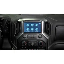
Compatible with IOK Touchscreen Radios
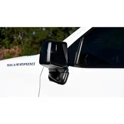
Silverado Light Duty Trucks (2022-Present)
Trailering Camera System
2
Installation Guide
2
tel - 1-866-766-2267
email - gmsupport@echomaster.com
Illustrations are typical and may not match exact vehicle detail
FCTP-GM2203
Trailering Camera System
Please read and follow the instructions carefully. To emphasize special information, the symbol
and the words Warning, Caution and Note have special meanings. Pay special attention to
messages highlighted by these signal words.
Note: Indicates special information to make installation easier or instructions clearer.
These instructions are designed as a guide to help make the installation of this product successful.
Always use caution and ask for assistance if you are not sure how to proceed.
Stinger Solutions & EchoMaster are not responsible for any damage that may occur during
installation or any changes to the vehicle interior.
Important
WARNING
Indicates a potential hazard
that could result in a death
or serious injury
CAUTION
Indicates a potential hazard
that could result in vehicle
damage
NOTE
Indicates a potential hazard
that could result in vehicle or
equipment damage
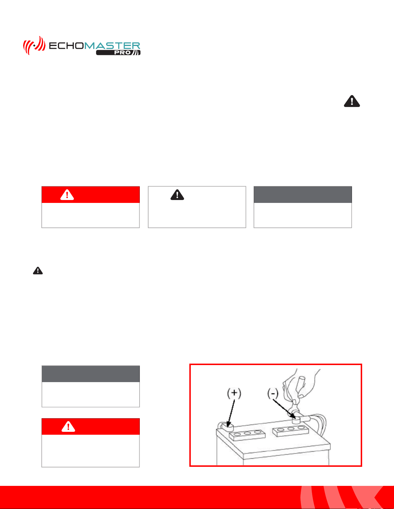
NOTE
Consult Vehicle owners guide
before disconnecting negative
battery cable
WARNING
DO NOT TOUCH the positive
terminal with any tool when
removing the negative battery
cable
Vehicle Preparation & Protection
Consult your vehicle owner’s manual to disconnect the battery. Do not disconnect ANY airbag connectors or
indicators. Doing so may result in activating a diagnostic code. These codes will require the dealer to perform
the reset procedure which may incur a reset fee. If you are unsure of any vehicle trim removal process consult
the OEM service manual.
Removing vehicle trim panels in extreme hot and/or cold climate could result in damage. Use care when
removing all vehicle trims. Using painter’s blue tape on the vehicle trim panels can help limit any scratches
and / or marring. Use a nylon trim panel removal tool whenever possible.
CAUTION
3
Installation Guide
3
tel - 1-866-766-2267
email - gmsupport@echomaster.com
Illustrations are typical and may not match exact vehicle detail
FCTP-GM2203
Trailering Camera System
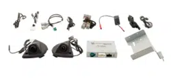
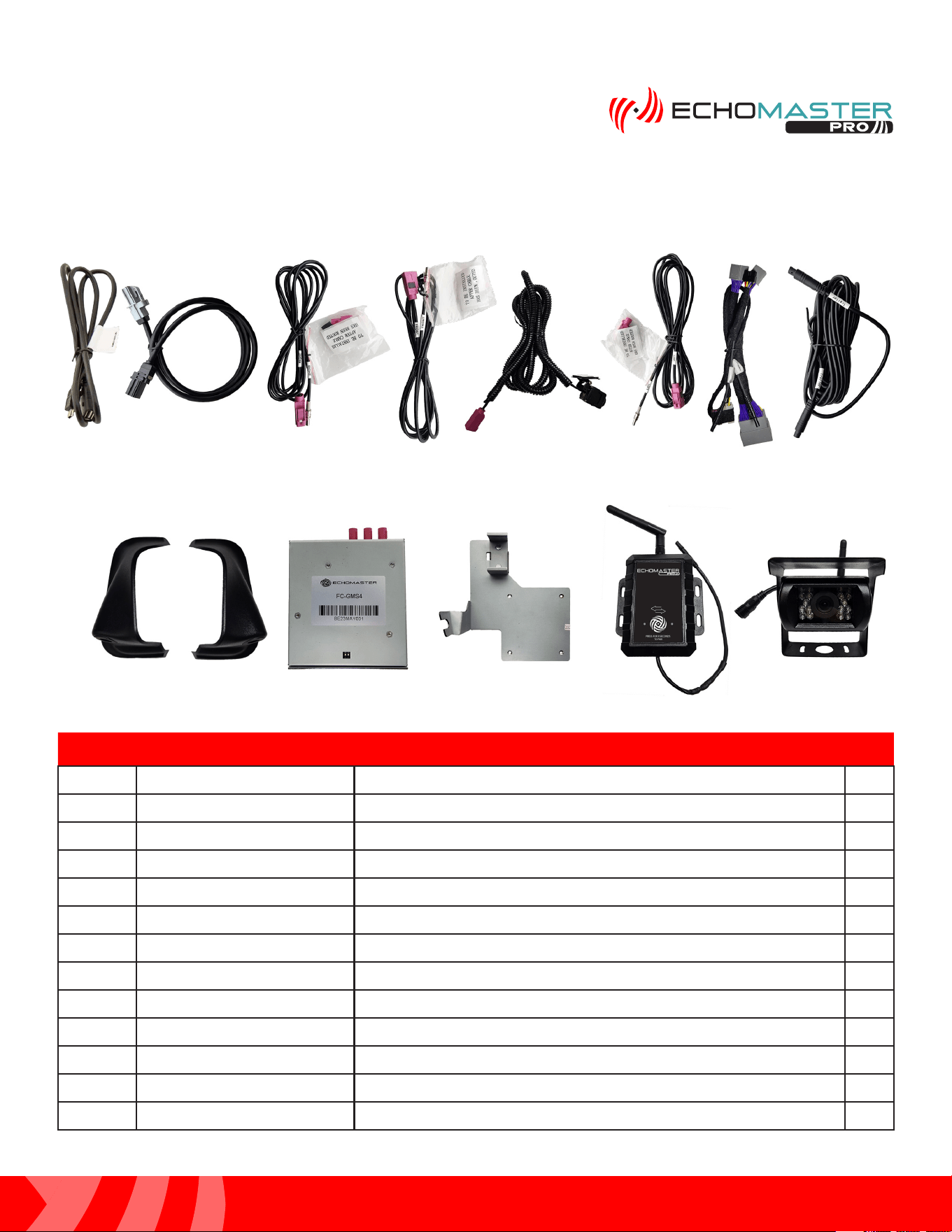
What’s in the Box
Parts Description
FCTP-GM2203
Image Part Number Description Qty
1
GMS4-USB-CBL USB Update Cable for FC-GMS3 Interface
1
2 GMS4-LVDS-HAR LVDS Harness for FC-GMS4
1
3
GMS4-M2F-72 72” RIGHT Camera Fakra Extension Harness
1
4 GMS4-M2F-50 50” FRONT Camera Fakra Extension Harness
1
5
PCAM-12FF Front Camera
1
6
GMS4-M2F-128 128” LEFT Camera Fakra Extension Harness
1
7 GMS4-PTH-HAR Power / CAN Harness for FC-GMS4
1
8 RVC-W9-RXEXT RVC-W9 Wireless Receiver Extension Harness 1
9
SCPT1LD/SVC-04 Side Mirror Cap Camera Mounts (L&R)/Cameras
1
10
FC-GMS4 Interface Module For 2022+ GM Trucks
1
11
FC-GMS4-BRK Mounting Bracket for FC-GMS4
1
12
RVC-W9 Wireless Trailer Camera and Receiver
1
1
2
3 4 5 6
9 10 11
12
7 8
4
Installation Guide
4
tel - 1-866-766-2267
email - gmsupport@echomaster.com
FCTP-GM2203
Trailering Camera System
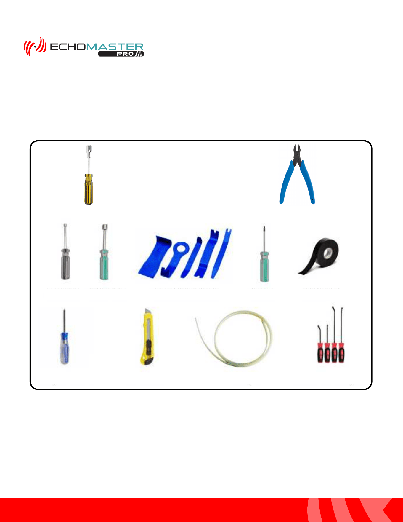
Tools Required
13mm Driver
Flush Cutters
10mm Driver
Nylon Trim Removal Tools
Torx - 15 Electrical Tape
Phillips Screw Driver Razor Knife Fish Tape Small Flat Blade Pry Tool
7mm Driver
5
Installation Guide
5
tel - 1-866-766-2267
email - gmsupport@echomaster.com
Illustrations are typical and may not match exact vehicle detail
FCTP-GM2203
Trailering Camera System
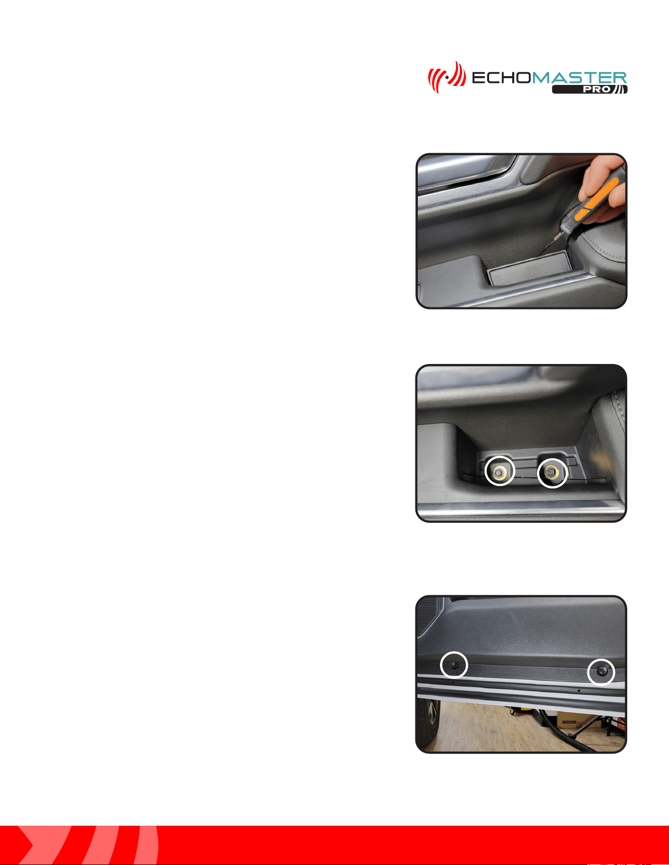
Step 1:
Using a small flat blade pry tool or similar, remove the inner
handle rubber cover to access the 7mm bolts underneath it.
Door Disassembly
Step 2:
Remove the 2 x 7mm bolts located underneath the inner
handle rubber cover.
Step 3:
Locate and remove the 2 x 7mm bolts at the bottom edge of
the door panel.
6
Installation Guide
6
tel - 1-866-766-2267
email - gmsupport@echomaster.com
Illustrations are typical and may not match exact vehicle detail
FCTP-GM2203
Trailering Camera System
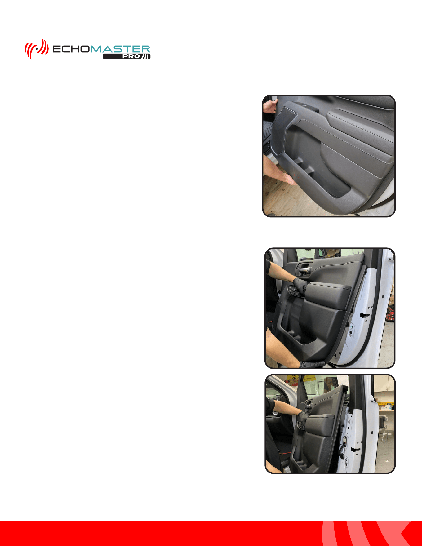
Door Disassembly (continued)
Step 4:
Starting at the top inside edge of the door panel, pull the
panel towards you to release the fasteners, working your
way down and towards the rear of the door and then back
up and towards the door lock post.
Step 5:
Once all the fasteners have been released in step 6, lift up
on the door panel to remove it from the door.
7
Installation Guide
7
tel - 1-866-766-2267
email - gmsupport@echomaster.com
Illustrations are typical and may not match exact vehicle detail
FCTP-GM2203
Trailering Camera System
Once the door panel is removed, place in a safe area to
avoid damage.
NOTE
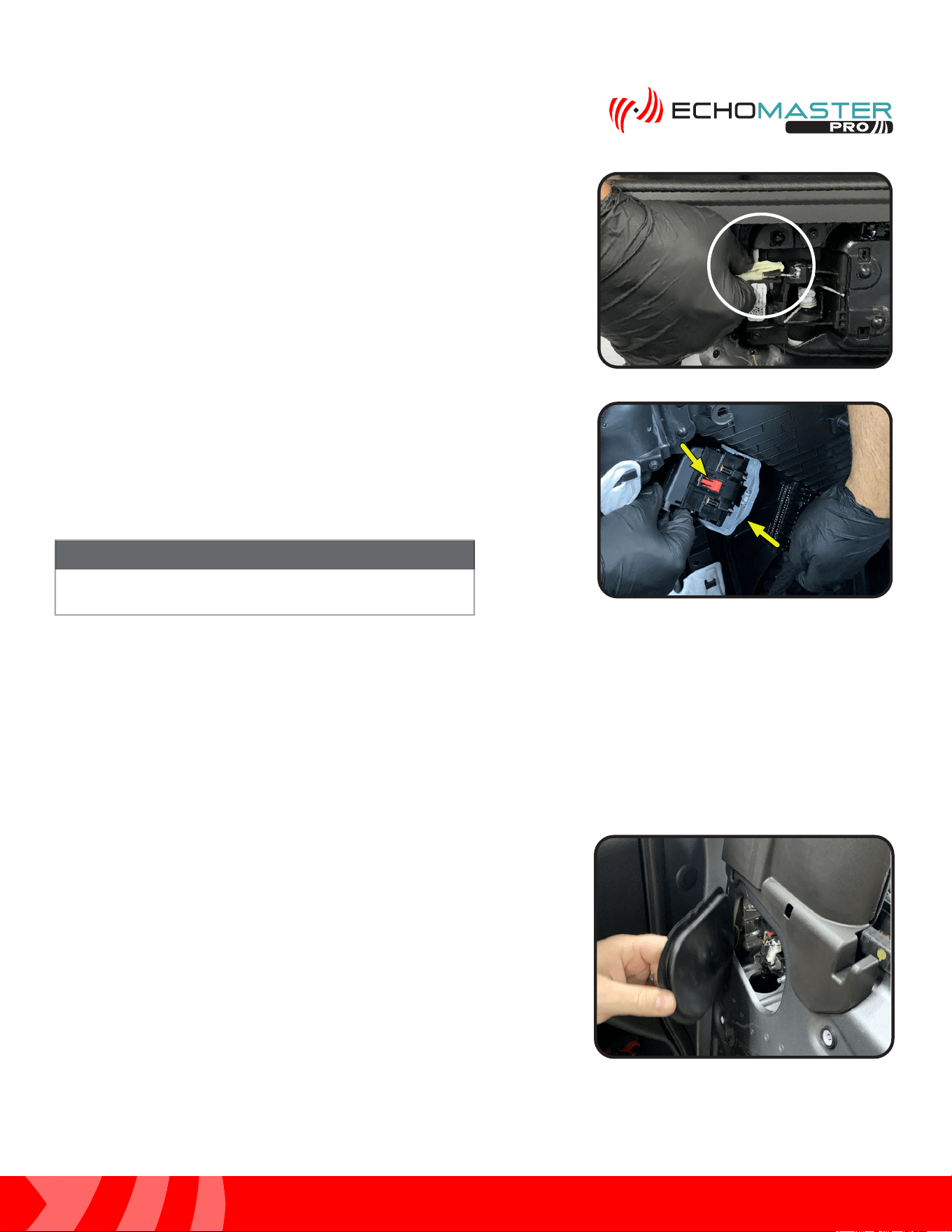
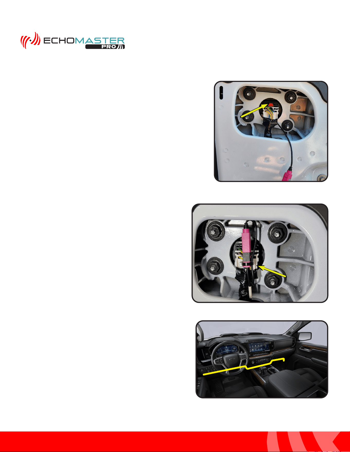
Step 7:
With the door panel still leaned toward you and away from
the door, disconnect the door harness. Do this by releasing
the Red locking tab and rotating the large Gray slide lock tab
towards the ground.
Step 6:
With the door panel leaned toward you and away from
the door, remove the door latch release cable. Do this by
pressing down on the tab, pulling back and then rotating the
fastener 90 degrees towards the door until the cable is able
to lift out of the retainer.
Red LockingRed Locking
Tab Tab
Gray SlideGray Slide
Lock Lock
Step 1:
Remove the plastic cap on the upper inside corner of the
door to gain access to the factory mirror connector.
Removing the Mirrors
8
Installation Guide
8
tel - 1-866-766-2267
email - gmsupport@echomaster.com
Illustrations are typical and may not match exact vehicle detail
FCTP-GM2203
Trailering Camera System
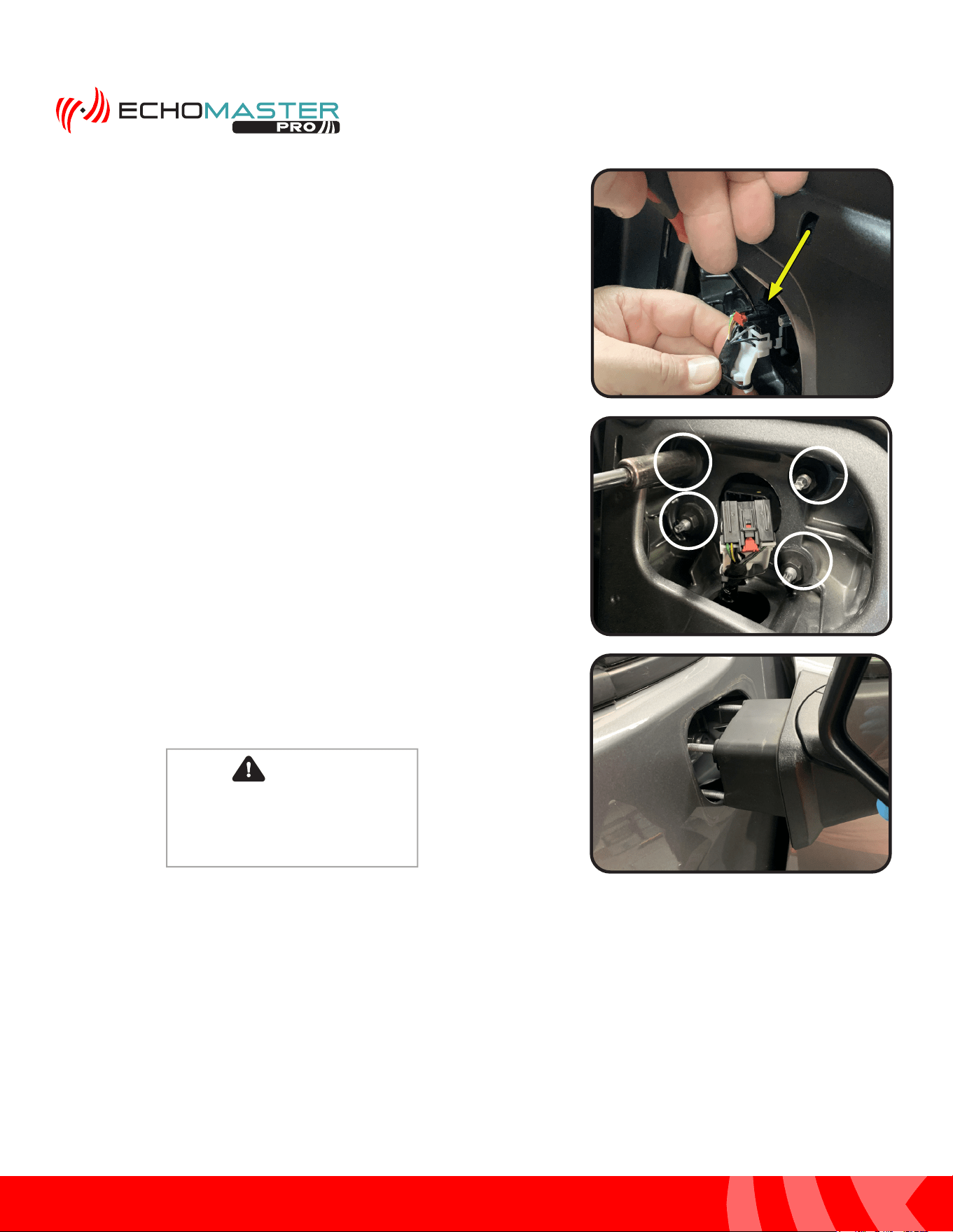
Step 3:
Remove the (4) x 13mm nuts from the inside of the door that
secure the mirror to the door. When removing the last one,
please ensure that the mirror is supported from the outside.
Failure to do this may result in damaging the mirror. Pull the
mirror away from the door.
Step 2:
Using a small flat blade pry tool or similar, release the Red
safety lock and depress the tab to release the connector from
the mirror.
CAUTION
Failure to support the mirror when
removing the 13mm nuts could result
in the mirror falling and breaking.
9
Installation Guide
9
tel - 1-866-766-2267
email - gmsupport@echomaster.com
Illustrations are typical and may not match exact vehicle detail
FCTP-GM2203
Trailering Camera System
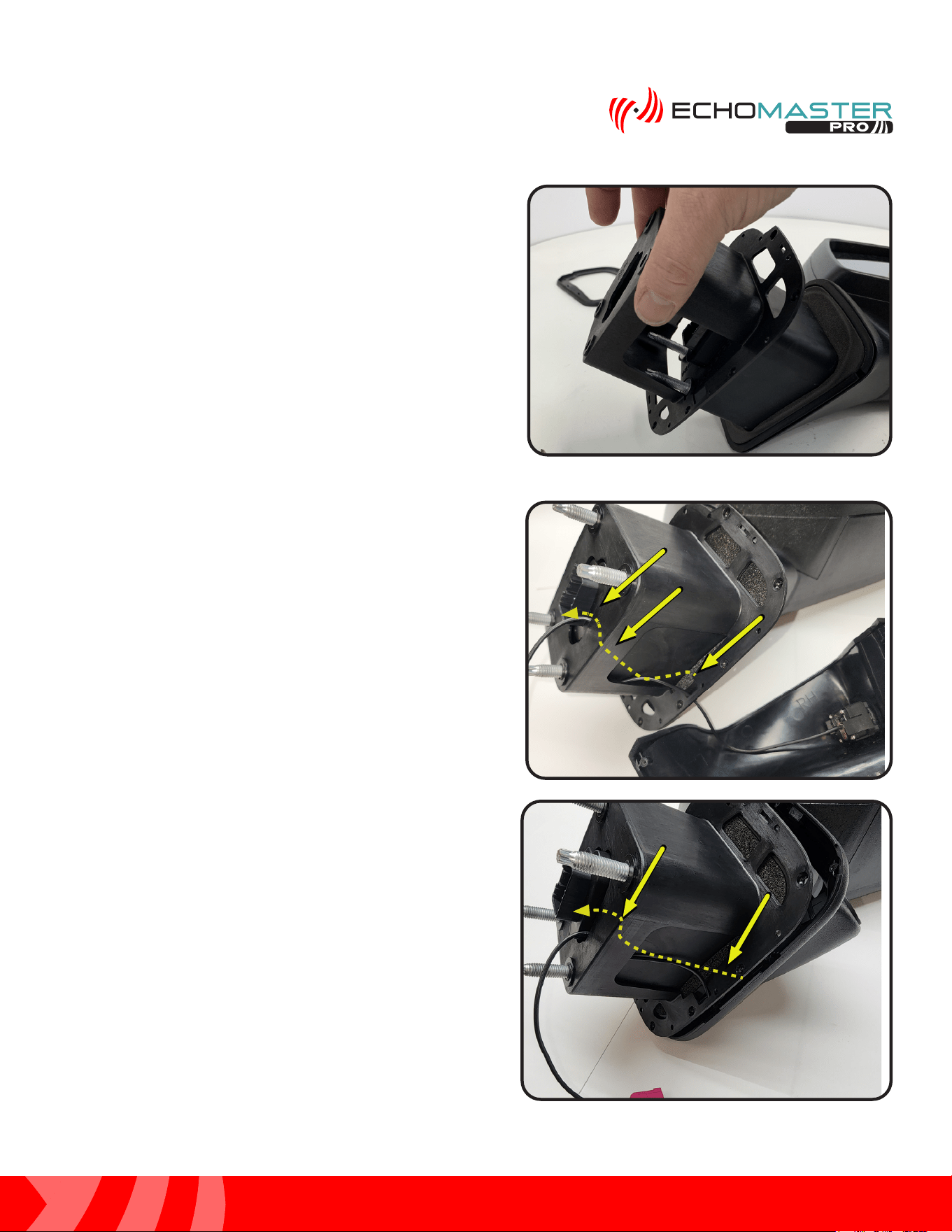
Step 1:
Slide the camera pod bucket onto the mounting base of the
mirror.
Step 2:
Route the camera cable through the notch in the bucket
and out the back of the bucket by the mirror’s connector.
Installing the Camera Pods
10
Installation Guide
10
tel - 1-866-766-2267
email - gmsupport@echomaster.com
Illustrations are typical and may not match exact vehicle detail
FCTP-GM2203
Trailering Camera System
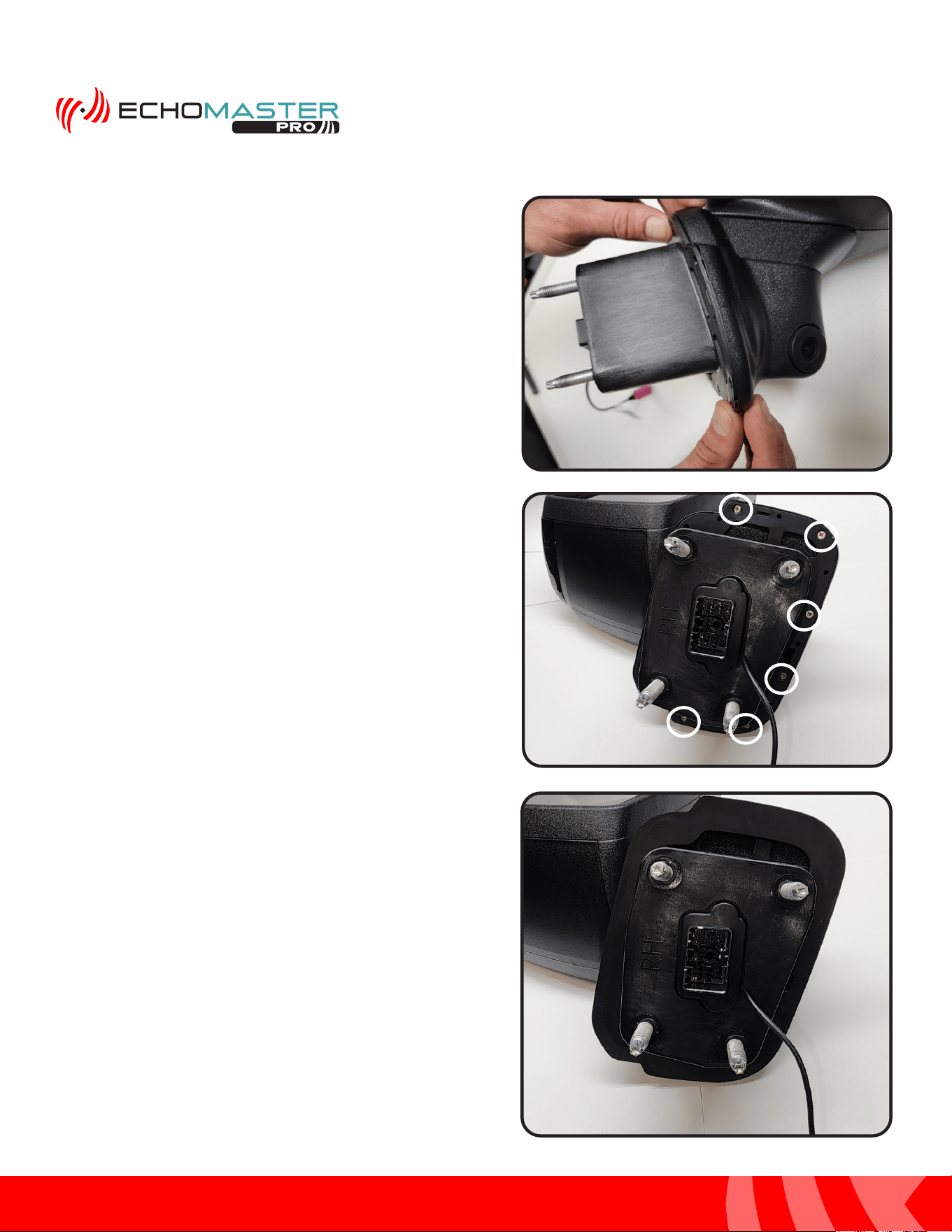
Step 3:
Line up the bucket and the camera pod and snap the two
together.
Step 5:
Install the rubber gasket making sure the alignment posts
line up with the openings in the bucket so that the gasket
sits tight against the bucket all the way around.
Step 4:
Install the supplied (x6) Phillips head screws to secure the
bucket to the camera pod using a #1 Phillips head screw
driver.
Installing the Camera Pods (continued)

11
Installation Guide
11
tel - 1-866-766-2267
email - gmsupport@echomaster.com
Illustrations are typical and may not match exact vehicle detail
FCTP-GM2203
Trailering Camera System
Step 6:
Feed the cable through the harness opening of
the door and re-install the mirror back onto the
vehicle making sure the bolt studs line up with
the holes in the door. At this time check that the
camera cable has not been pinched during this
step and secure the mirror to the door using the
factory hardware. Next, move on to routing the
camera extension cables.
Routing the Camera Cables
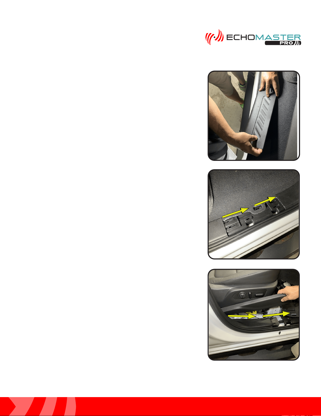
Step 1:
Remove the door sill plate. Begin by
removing the side seat trim panel by
pulling up. Then, using a plastic trim tool
starting at the rear, pry up and remove the
door sill panel. Work your way forward and
release from the kick area.
Once the door sill plate is removed, place in
safe area to avoid damage.
NOTE
12
Installation Guide
12
tel - 1-866-766-2267
email - gmsupport@echomaster.com
Illustrations are typical and may not match exact vehicle detail
FCTP-GM2203
Trailering Camera System
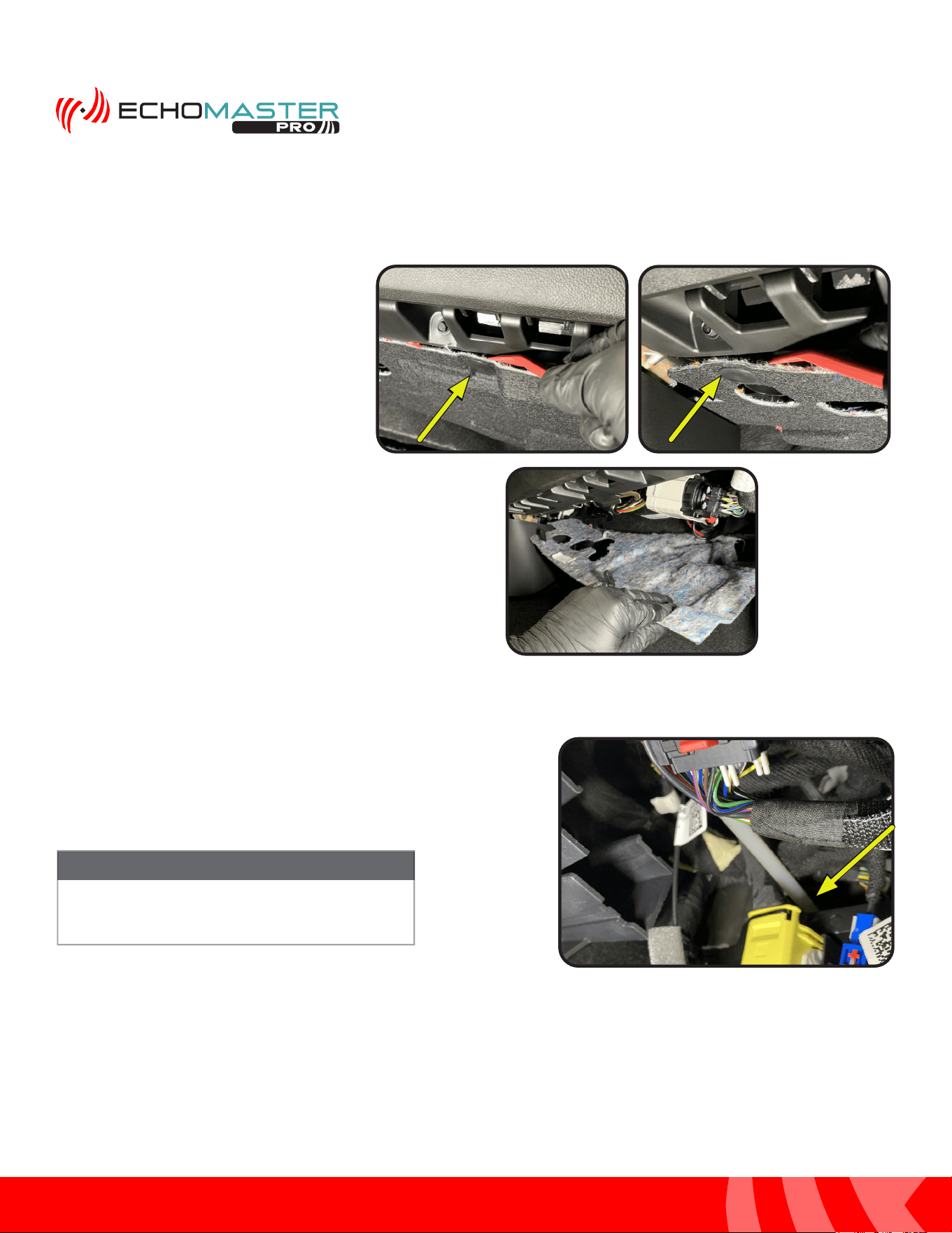
Step 2:
Remove the under dash beauty panel,
if present, by removing the push pin
fasteners.
(2 under the glove compartment and 1
towards the front of the vehicle)
Step 3:
From inside the vehicle: route the fish tape along the factory
wiring, exiting the vehicle just below the factory door connector.
Depending on the vehicle’s trim level, it may be
easier to route the fish tape from outside of the
vehicle to inside of the vehicle.
NOTE
Routing the Camera Cables (continued)
13
Installation Guide
13
tel - 1-866-766-2267
email - gmsupport@echomaster.com
Illustrations are typical and may not match exact vehicle detail
FCTP-GM2203
Trailering Camera System
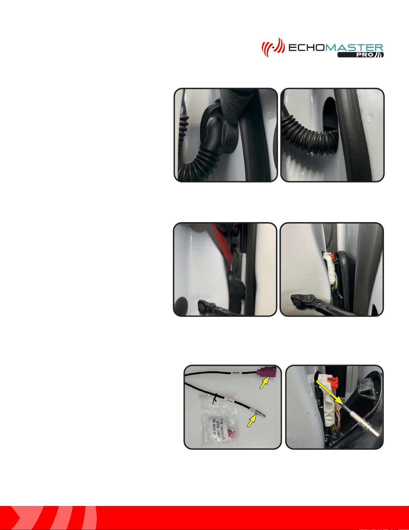
Step 6:
Locate GMS4-M2F-72 (RIGHT) or GMS4-
M2F-128 (LEFT) and remove the small ziploc
bag and set it aside. The connector housing
will be installed after the cable is routed.
Secure the bare connector end of the camera
extension cable to the fish tape using electrical
tape. The cable will be routed from the interior
of the vehicle to the exterior.
Module Module
ConnectorConnector
Camera Camera
ConnectorConnector
Step 4:
Push the door side of the wire boot into
the door.
Step 5:
Release the top of the door boot on the
vehicle side using a plastic trim tool.
14
Installation Guide
14
tel - 1-866-766-2267
email - gmsupport@echomaster.com
Illustrations are typical and may not match exact vehicle detail
FCTP-GM2203
Trailering Camera System
Routing the Camera Cables (continued)
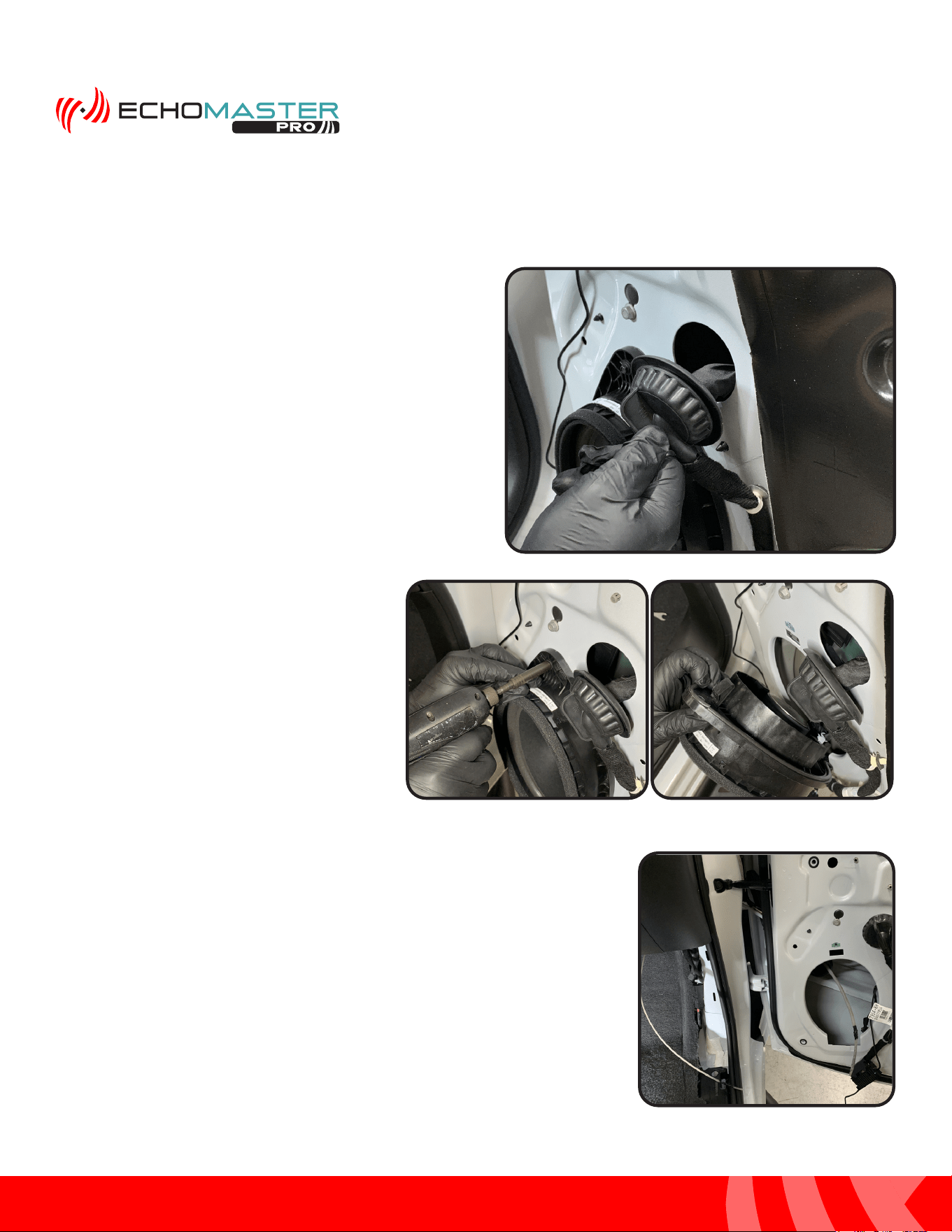
Step 9:
With the speaker removed, continue routing the fish tape through
the door boot and into the door cavity exiting the speaker opening.
Step 8:
Remove the 7mm bolt securing the speaker,
unplug the speaker and set aside. This will
aide in routing the camera cable in the door.
Step 7:
Release the rubber grommet from the
door by grabbing and pulling on the
attached tab.
15
Installation Guide
15
tel - 1-866-766-2267
email - gmsupport@echomaster.com
Illustrations are typical and may not match exact vehicle detail
FCTP-GM2203
Trailering Camera System
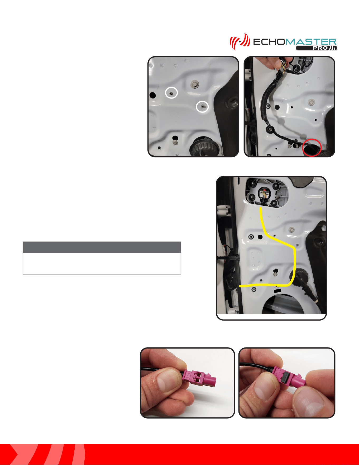
Step 10:
Locate the 2 gray retention clips, circled in
yellow, holding the mirror harness to the
inside of the door. Squeeze the sides and
push them in to release the harness. Pull
the harness through the opening, circled
in red, to easily route and secure the
camera extension harness to the factory
wiring.
Step 12:
With the camera extension harness
now routed and secured to the factory
wiring, install the connector housing on
the bare connector end of the extension
harness. First, slide the pink housing
onto the connector. Then, slide the black
retention clip onto the pink housing
locking the connector in place.
Step 11:
Secure the camera extension cable to the factory door
harness using the supplied zip ties. The cable will follow the
path outlined in yellow when it is secured to the factory wiring
harness. This will ensure that the cable is in an unobstructed
path into the vehicle through the door boot.
The camera cables must be run with and secured to the
factory wiring. Failure to do this WILL result in damage to
the camera extension cables.
NOTE
16
Installation Guide
16
tel - 1-866-766-2267
email - gmsupport@echomaster.com
Illustrations are typical and may not match exact vehicle detail
FCTP-GM2203
Trailering Camera System
Step 14:
Connect the GMS4-M2F-72 (RIGHT) or the
GMS4-M2F-128 (LEFT) to the camera cable and push them
together until fully seated. You will hear an audible click
when the connectors lock together. Secure the connector
to the factory mirror connector using a zip tie.
Step 15: (Driver Side Only)
Route the cable following the factory wiring to the
passenger side kick area and be sure to keep the cable
away from any moving parts.
Perform Steps 1-14 for the driver’s side door.
Routing the Camera Cables (continued)
Step 13:
Connect the mirror harness to the mirror and push in the
locking tab.
17
Installation Guide
17
tel - 1-866-766-2267
email - gmsupport@echomaster.com
Illustrations are typical and may not match exact vehicle detail
FCTP-GM2203
Trailering Camera System
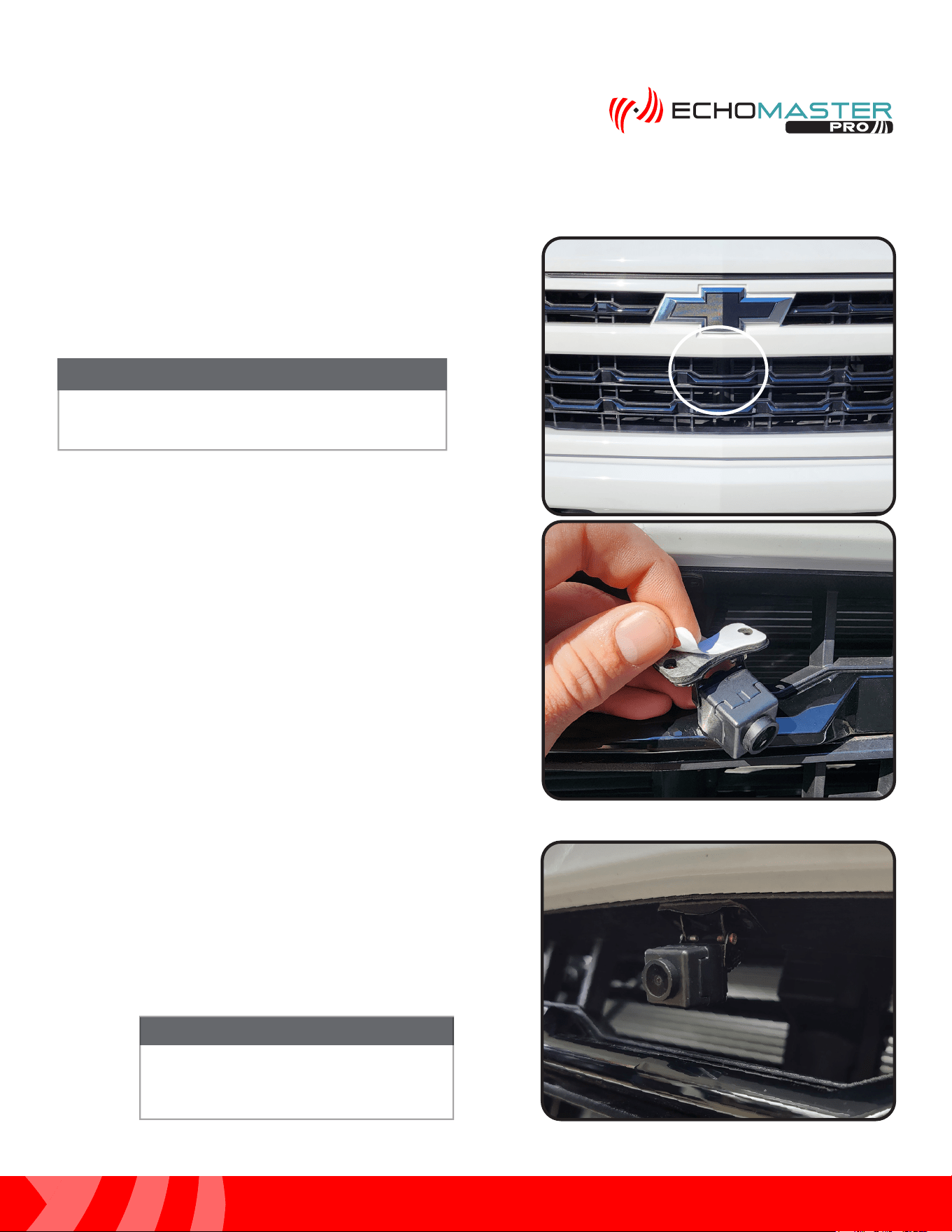
PCAM-12FF Installation: Camera Installation
Step 1:
Find the desired mounting location.
Step 2:
Remove the adhesive backing from the mounting base of the
camera.
Step 3:
Clean the surface and secure the camera to the grill in the
desired mounting location. At this time, install the included
mounting screws.
PLEASE NOTE
The recommended mounting location is
centered on the grill and just below the emblem.
NOTE
The installation of the mounting screws is
an optional step and is at the discretion of
the installer.
NOTE
18
Installation Guide
18
tel - 1-866-766-2267
email - gmsupport@echomaster.com
Illustrations are typical and may not match exact vehicle detail
FCTP-GM2203
Trailering Camera System
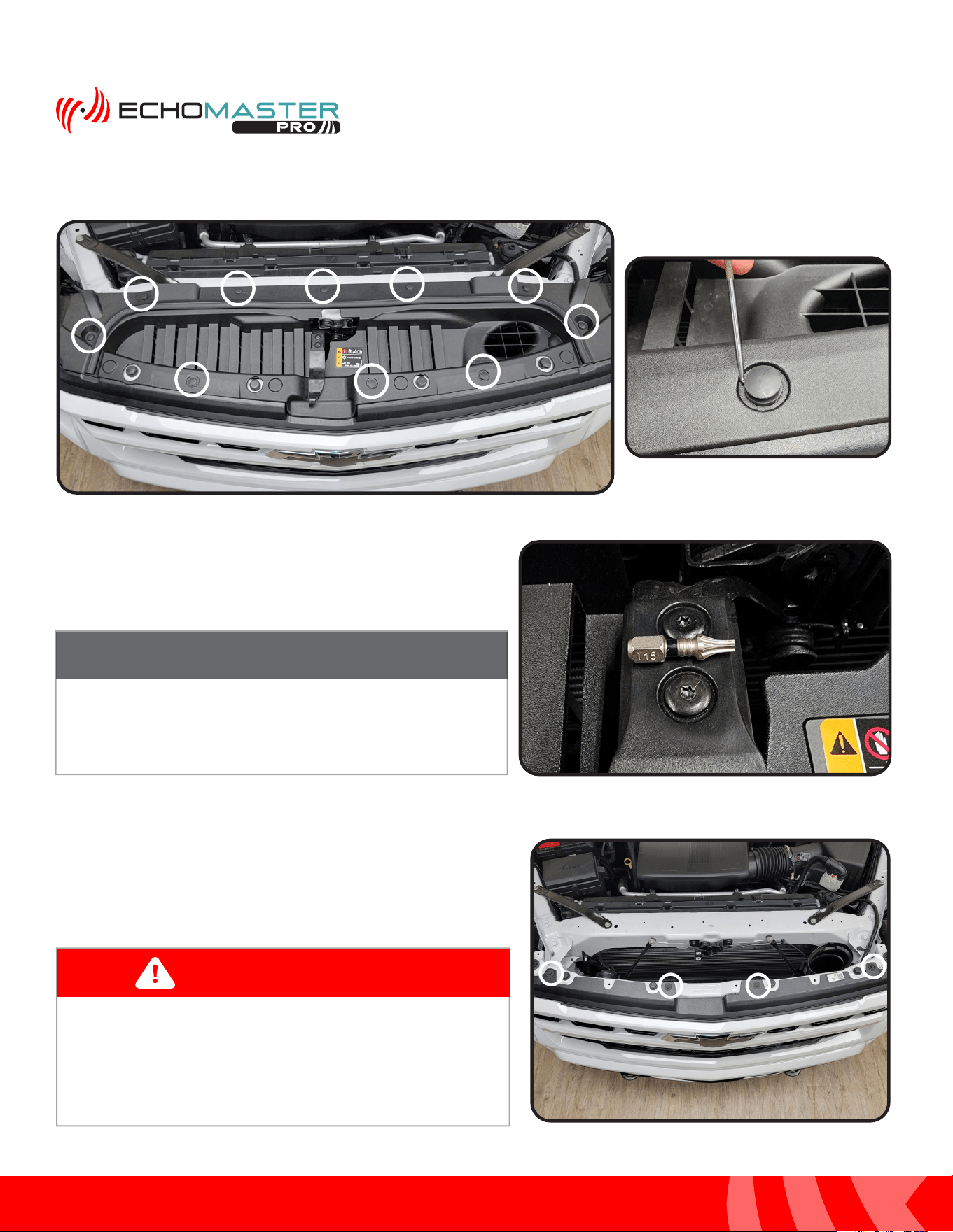
Step 4:
Using a small flat blade tool or similar, remove the 10 push-in rivets to remove the plastic trim panel on the
top side of the grill.
Step 5:
Remove the (x2) T15 screws attaching the hood release
handle to the hood release. Remove both the handle and
the trim panel and set aside.
Step 6:
Remove the 4 x 10mm bolts, circled in yellow, holding the
front fascia to the front frame rail of the vehicle.
Once the handle and trim panel are removed, place in
safe area to avoid damage.
NOTE
These vehicles have shutters behind the grille that open
and close. Be sure to route the camera cable to avoid
moving parts.
WARNING
19
Installation Guide
19
tel - 1-866-766-2267
email - gmsupport@echomaster.com
Illustrations are typical and may not match exact vehicle detail
FCTP-GM2203
Trailering Camera System
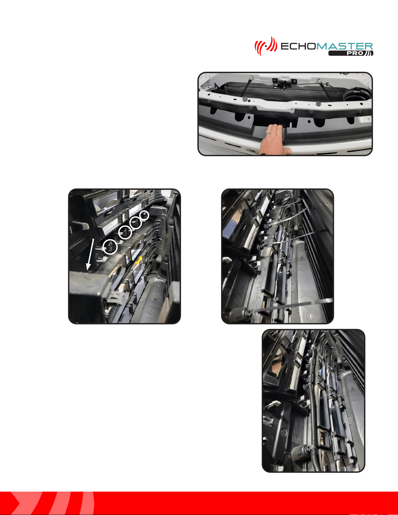
Step 7:
After removing the 10mm bolts, carefully pull the
front fascia trim away from the frame rail.
Step 8:
Locate 5 open mounting holes in the back of the front fascia and insert the provided zip ties with attached
christmas tree push fasteners.
Step 9:
Route the camera cable up from where the camera is mounted and along
the backside of the front fasicia towards the passenger side of the vehicle
using the zip ties to secure the cable in place.
20
Installation Guide
20
tel - 1-866-766-2267
email - gmsupport@echomaster.com
Illustrations are typical and may not match exact vehicle detail
FCTP-GM2203
Trailering Camera System
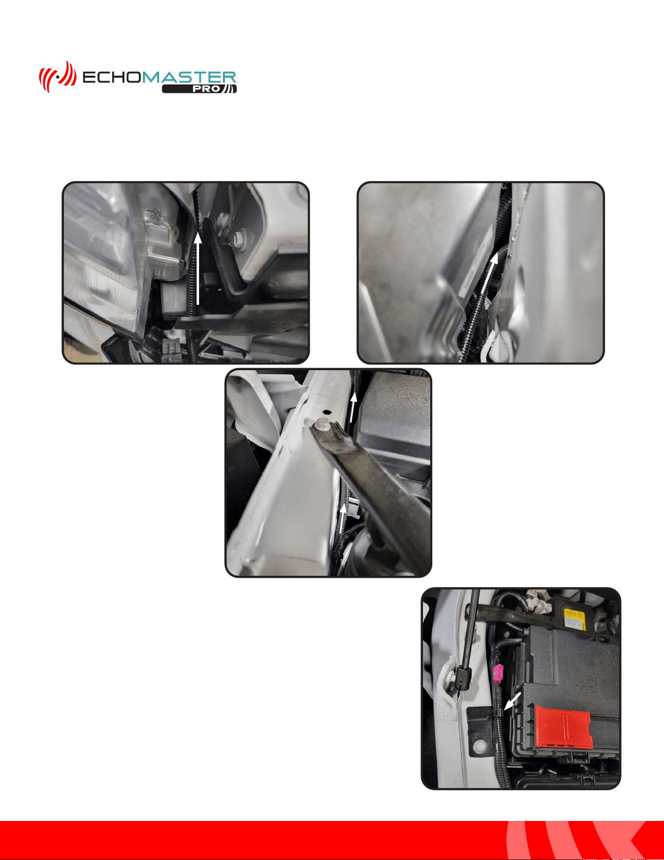
Step 10:
Continue routing the cable along the side of the passenger headlight as shown below. Route the
cable through the opening behind the headlight and up between the frame rail and fuse box and
battery.
Step 11:
Secure the connector to the factory harness near the battery using a
zip tie where shown.
21
Installation Guide
21
tel - 1-866-766-2267
email - gmsupport@echomaster.com
Illustrations are typical and may not match exact vehicle detail
FCTP-GM2203
Trailering Camera System
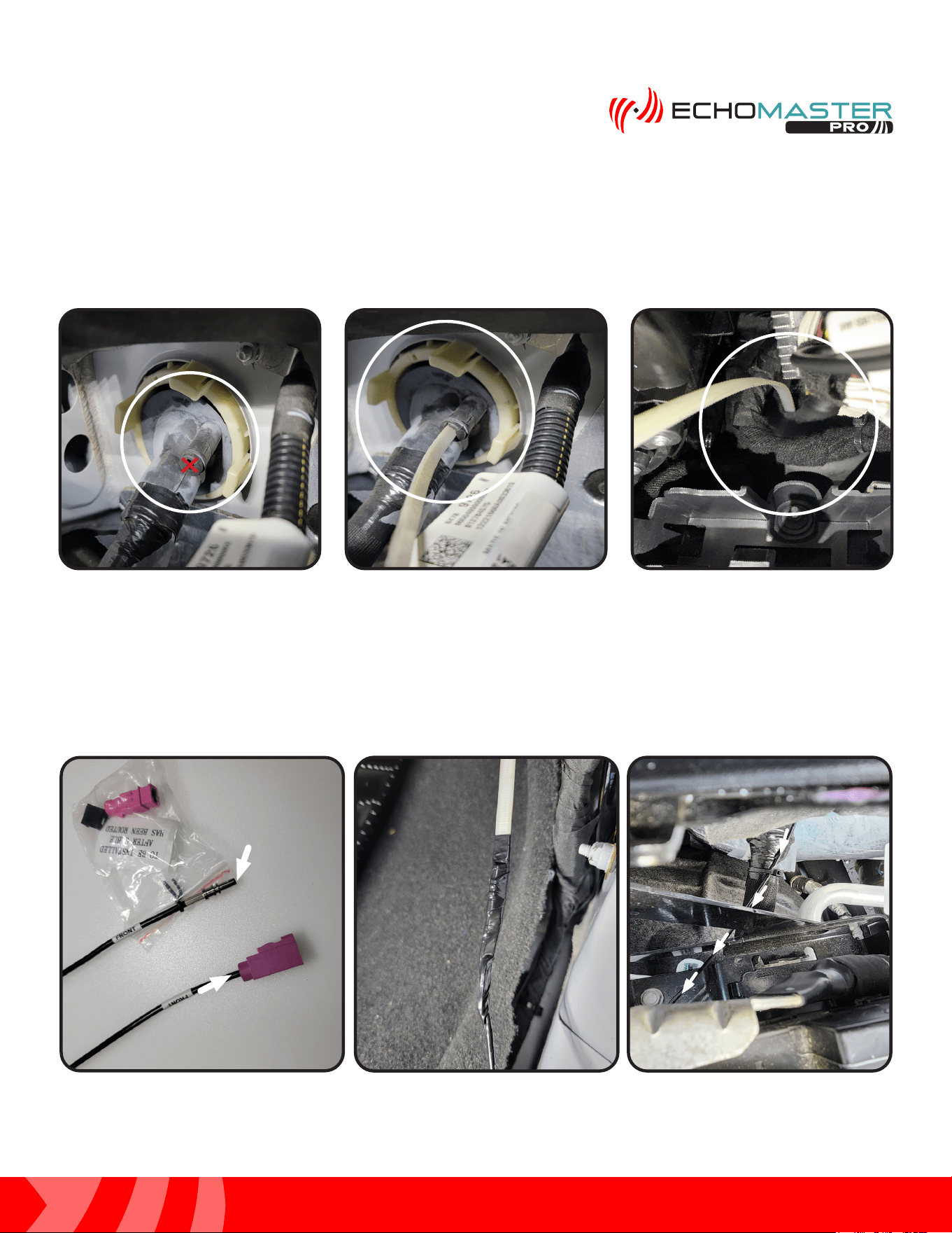
PCAM-12FF: Routing the Camera Extension Harness
Step 1:
From the engine bay side, cut a small slit or X, marked in red, in the aftermarket tunnel provision of the large
grommet located just behind the battery. Feed a wire fishing tool through the opening and into the cab of the
vehicle.
Step 2:
Locate GMS4-M2F-50, the Front Camera Extension Harness. Remove the small ziploc bag and set aside.
The connector housing will be installed after the cable is routed. From the inside of the vehicle, secure the
bare connetor end of the cable to the wire fishing tool. Slowly pull the cable into the engine bay and route
the cable along the factory wiring towards the previously ran camera cable. Secure the extension harness to
the factory wiring bundle using a zip tie.
Module Module
ConnectorConnector
Camera Camera
ConnectorConnector
22
Installation Guide
22
tel - 1-866-766-2267
email - gmsupport@echomaster.com
Illustrations are typical and may not match exact vehicle detail
FCTP-GM2203
Trailering Camera System
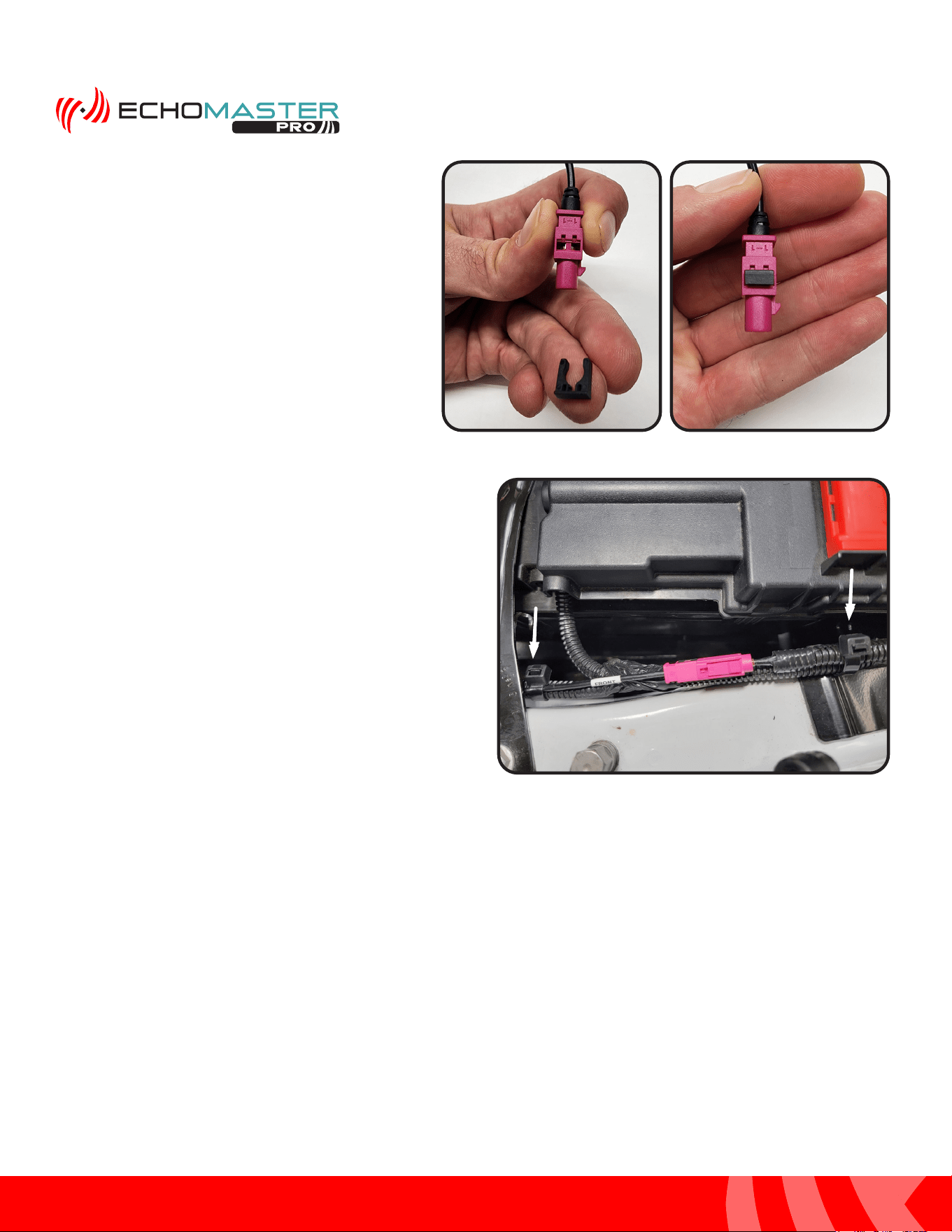
Step 4:
With the connector housing now installed, connect
the extension harness to the previously routed
camera cable. You will hear an audible click when
the connectors are fully seated together. Secure
the cable to the factory harness with zip ties where
shown.
Step 3:
With the extension harness now routed, grab
the small plastic bag containing the connector
housing and retention clip. First, slide the pink
connector housing on to the bare connector
end. Then, slide the black retention clip onto the
connector housing to secure the connector.
23
Installation Guide
23
tel - 1-866-766-2267
email - gmsupport@echomaster.com
Illustrations are typical and may not match exact vehicle detail
FCTP-GM2203
Trailering Camera System
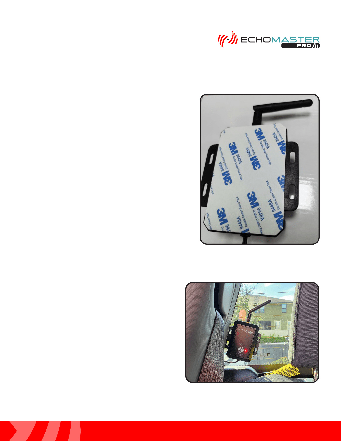
Rear Wireless Camera Receiver Installation
Step 1:
Locate the Wireless Camera Receiver with the pre-attached
3M double sided tape and prepare to mount it to the back
glass.
Step 2:
Clean the surface and secure the wireless camera
receiver to the back window as shown in the picture.
24
Installation Guide
24
tel - 1-866-766-2267
email - gmsupport@echomaster.com
Illustrations are typical and may not match exact vehicle detail
FCTP-GM2203
Trailering Camera System
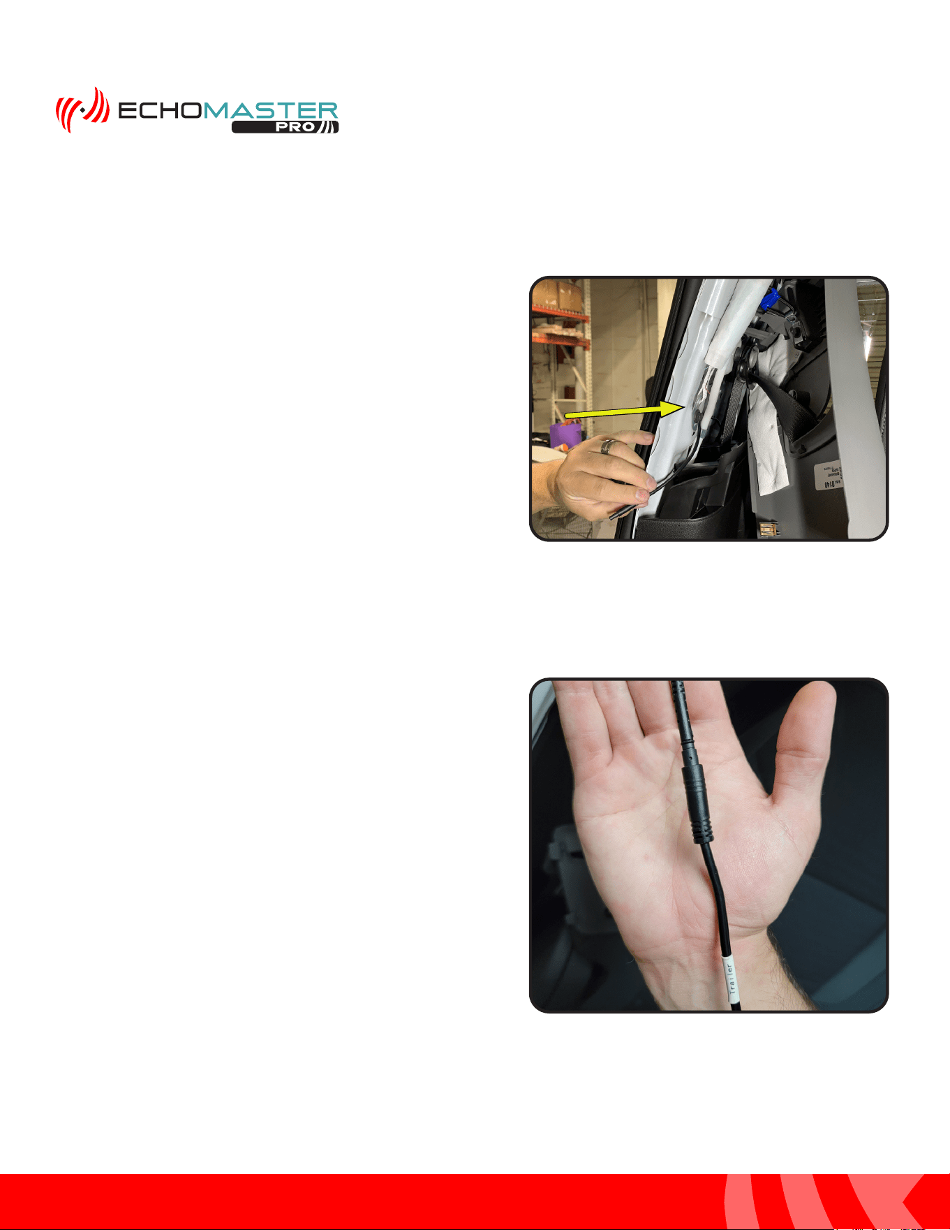
Step 3:
Release the retaining clips and remove the upper trim panel
from the C pillar and route the pigtail cable from the wireless
camera receiver. Make certain the cable is routed behind
any air bag hardware that is located in that area.
Rear Wireless Camera Receiver (continued)
Step 4:
Connect the 4 pin mini din cable from the wireless camera
receiver to the corresponding connector end of the Trailer
Camera Extension cable.
25
Installation Guide
25
tel - 1-866-766-2267
email - gmsupport@echomaster.com
Illustrations are typical and may not match exact vehicle detail
FCTP-GM2203
Trailering Camera System
Step 5:
Remove the passenger side rear door sill using a plastic
trim tool. Pull loose the rubber door seal between the rear
door sill and the upper trim panel removed in step 3.
Step 7:
Remove the front passenger seat trim panel and continue
routing the cable to the passenger kick area. Tuck the
cable behind the trim panels and under the carpet while
routing it to the front of the vehicle. Leave the connector
accessible in the passenger kick area to be connected in a
later step.
Step 6:
Tuck the in-line filter box behind the trim panel and route
the RVC-W8-FLTR cable down from the power filter to the
floor area, then towards the front of the vehicle. Tuck the
cable behind the trim panels and under the carpet while
routing it to the front of the vehicle.
26
Installation Guide
26
tel - 1-866-766-2267
email - gmsupport@echomaster.com
Illustrations are typical and may not match exact vehicle detail
FCTP-GM2203
Trailering Camera System
Module Assembly and Installation
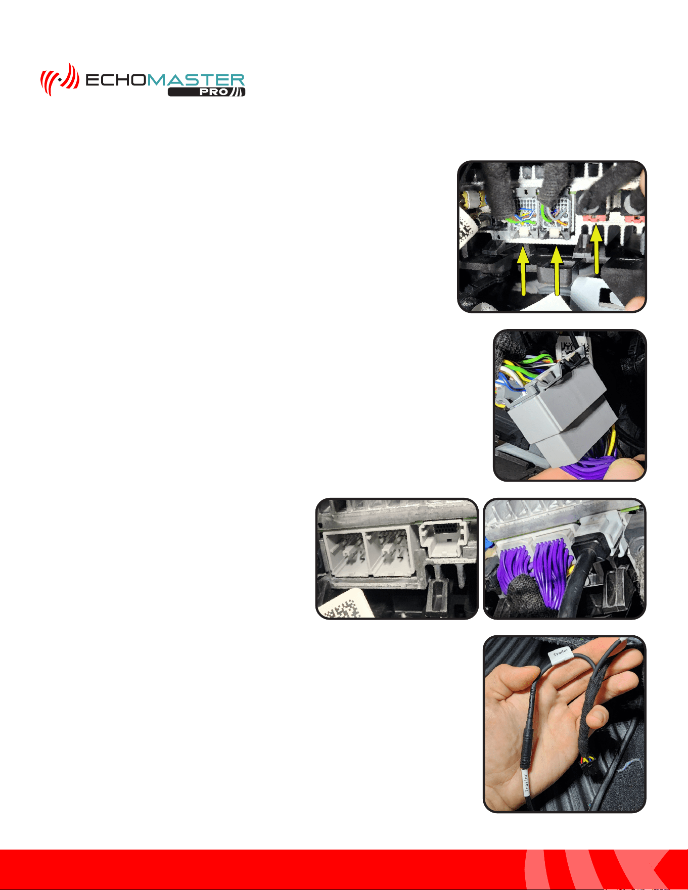
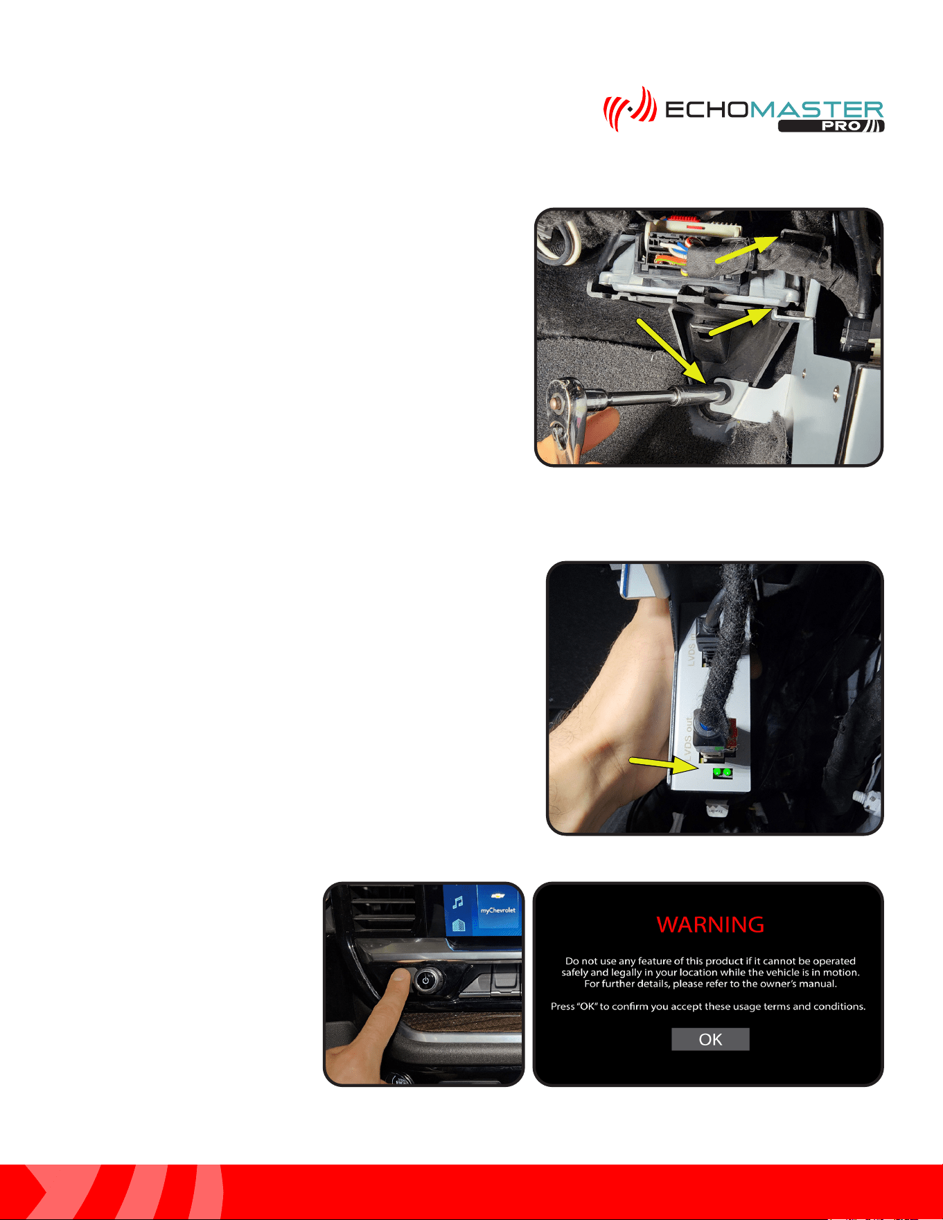
Step 1:
Locate the factory radio receiver high in the passenger side kick area.
Disconnect the Gray and Black 28 pin connectors along with the LVDS
cable which is located next to the Black 28 pin connector. The LVDS
connector can easily be identified as it will have the Blue cable.
Step 2:
Connect the factory Gray and Black 28 pin connectors to the GMS4-PTH-HAR.
Step 3:
Connect the 2 Gray 28 pin connectors from the
GMS4-PTH-HAR and the Gray LVDS connector
from the GMS4-LVDS-HAR into the factory radio
receiver.
Step 4:
Connect the TRAILER extension harness to the corresponding connector
labeled “TRAILER” on the GMS4-PTH-HAR harness.
27
Installation Guide
27
tel - 1-866-766-2267
email - gmsupport@echomaster.com
Illustrations are typical and may not match exact vehicle detail
FCTP-GM2203
Trailering Camera System
Step 6:
Connect the factory LVDS cable and GMS4-LVDS-HAR to the
GMS4 module. Make certain all connectors are fully seated
before proceeding with the install.
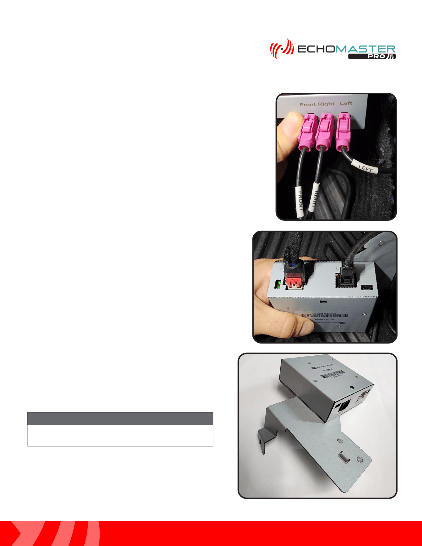
Step 5:
Connect the GMS4-M2F camera extension harnesses to each of the
corresponding connectors on the module. Line up the labels and connect
in the following orientation:
CONNECTIONS ON MODULE
RIGHT ----------------- GMS4-M2F-72
LEFT ------------------- GMS4-M2F-128
FRONT ---------------- GMS4-M2F-50 (Optional Front Camera)
CONNECTIONS ON GMS4-PTH-HAR
TRAILER -------------- TRAILER
OTHER --------------- TRAILER (Optional 2nd Trailer Camera)
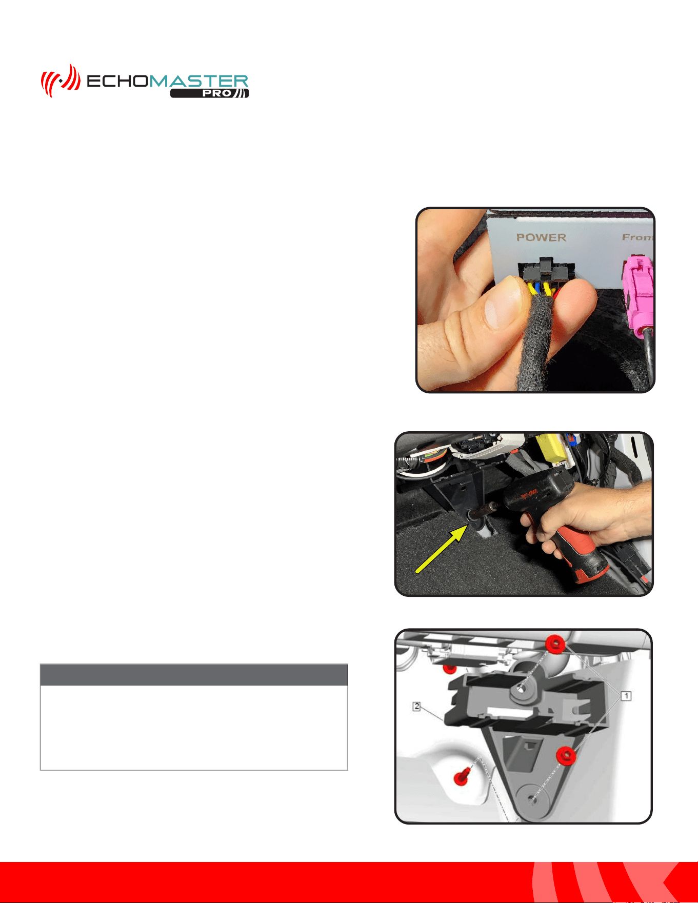
Step 7:
At this time, make sure that both DIP switches are in
the OFF position. They are only necessary if there is an
available firmware update.
DIP switches must be set prior to connecting the module
to the vehicle.
NOTE
28
Installation Guide
28
tel - 1-866-766-2267
email - gmsupport@echomaster.com
Illustrations are typical and may not match exact vehicle detail
FCTP-GM2203
Trailering Camera System
Module Assembly and Installation (continued)
Step 9:
Remove the 10mm retaining nut from the plastic bracket in
the passenger side kick area.
If factory Multifunction Power Supply Converter
Bracket (#2) is not present, one will be needed along
with the 10mm fasteners (#1) for the module to
mount correctly. Please consult with your GM parts
department for ordering.
NOTE
Step 8:
Finally, connect the 10 pin Black connector from GMS4-PTH-HAR
to the GMS4 module.
29
Installation Guide
29
tel - 1-866-766-2267
email - gmsupport@echomaster.com
Illustrations are typical and may not match exact vehicle detail
FCTP-GM2203
Trailering Camera System
Step 1
Before turning the ignition to the ON position for the first time
after the installation is finished, re-conenct the battery if it
was disconnected at the beginning of the install. Then, make
certain that the LEDs at the top of the module have stopped
flashing. Failure to do this will render the touch screen
unresponsive. If you find that this step was not completed and
the touch screen is unresponsive, turn the vehicle’s ignition
to the OFF position and wait until the LEDs have stopped
flashing, then turn the vehicle’s ignition to the ON position.
Step 2
Once the radio finishes the boot
up sequence, press and hold the
HOME button for 3 seconds. The
WARNING screen will appear.
Press the OK button.
Testing & Setup
Step 10:
Place the GMS4 mounting bracket onto the vehicle’s
plastic Multifunction Power Supply Converter Bracket
bracket according to the picture. Make sure that the C
portion of the mounting bracket clips all the way around
the plastic factory bracket. Reinstall and tighten the 10mm
retaining nut.
30
Installation Guide
30
tel - 1-866-766-2267
email - gmsupport@echomaster.com
Illustrations are typical and may not match exact vehicle detail
FCTP-GM2203
Trailering Camera System
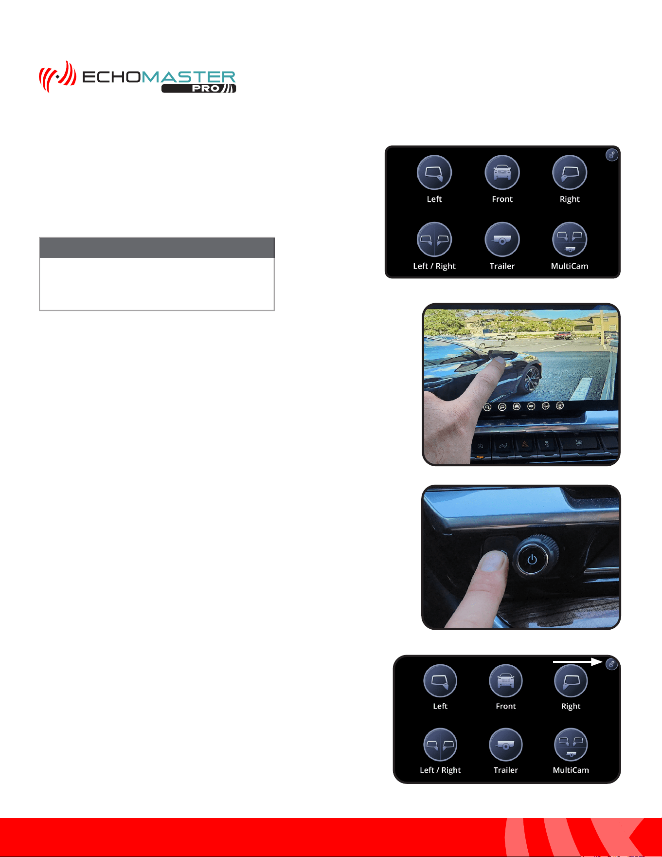
Step 3
Once the Intellihaul 3.0 home screen appears, press the
corresponding button for the camera you wish to test. Pressing
the HOME button on the radio’s control panel will return you to
the Intellihaul 3.0 home screen.
NOTE
If a camera is not installed and the button is
pressed for that camera, a black screen will
be visible. Press the HOME button to select
another camera.
Step 4
A minor camera view adjustment is built into each of the views.
If you wish to adjust the view of the selected camera press and
hold the center of the screen for 5 seconds. Without lifting your
finger, drag the image until the desired view is displayed and
then release.
Testing & Setup (continued)
Enabling the Front Camera
Step 1:
With the blind spot cameras properly adjusted, access the
Camera menu again by pressing and releasing the “HOME”
button on the factory dash panel.
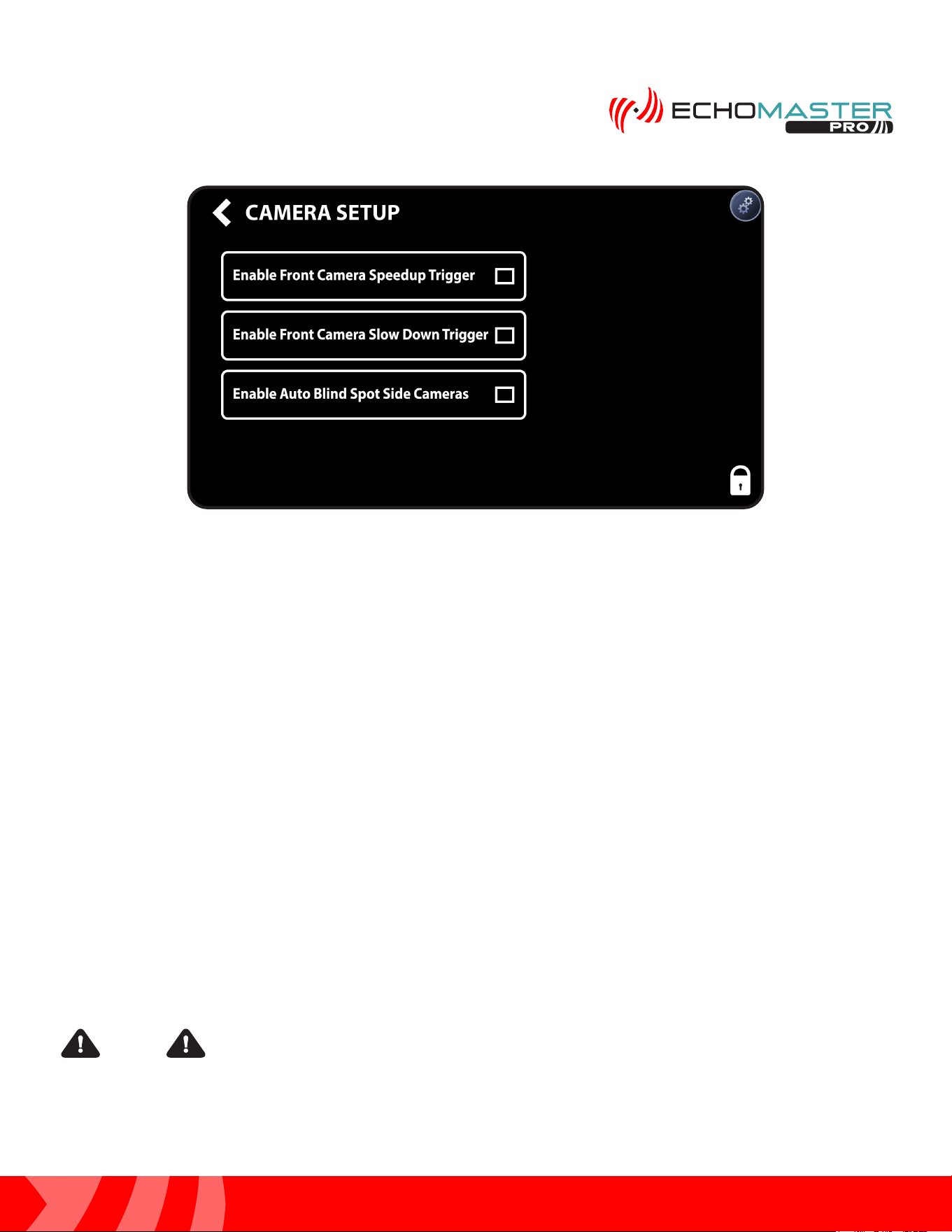
Step 2:
Access the Camera Setup menu by pressing the gear icon in the
top right corner to enter the camera setup menu.
31
Installation Guide
31
tel - 1-866-766-2267
email - gmsupport@echomaster.com
Illustrations are typical and may not match exact vehicle detail
FCTP-GM2203
Trailering Camera System
Additional Testing
Activate the right turn signal. Verify the right camera is displaying on the radio’s screen.
Activate the left turn signal. Verify the left camera is displaying on the radio’s screen.
Place your foot on the brake and place the vehicle in reverse. The rear camera will display on the screen.
Place the vehicle back in park to go to back to the main display.
Once proper operation has been confirmed, ensure all factory components are in working order (radio’s touch
screen, radio controls, etc.), it is now time to secure any loose components and/or cables and reassemble the
vehicle.
When using the Graphical User Interface and selecting camera views, you may run into
a situation where selecting a camera view triggers the icon in the upper left corner of the main radio screen. If
this occurs, it can be fixed by pressing and holding the icon in the upper left corner and dragging it off to the
center so that no icon will be present in the upper left corner.
Step 3:
Enabling one of the two Front camera options from the Camera Setup menu will enable the front camera in
the camera menu.
1. Enable Front Camera Speedup Trigger - When enabled, the front camera will display when exiting
reverse and turn off after 8 MPH.
2. Enable Front Camera Slow Down Trigger - When enabled, the front camera will display when speed
is reduced below 10MPH and the steering wheel is turned more than 15 degrees. This prevents unwanted
front camera activation in stop and go traffic. (Note: Vehicle speed must first exceed 15 MPH to activate this
feature)
NOTE
32
Installation Guide
32
tel - 1-866-766-2267
email - gmsupport@echomaster.com
FCTP-GM2203
Trailering Camera System
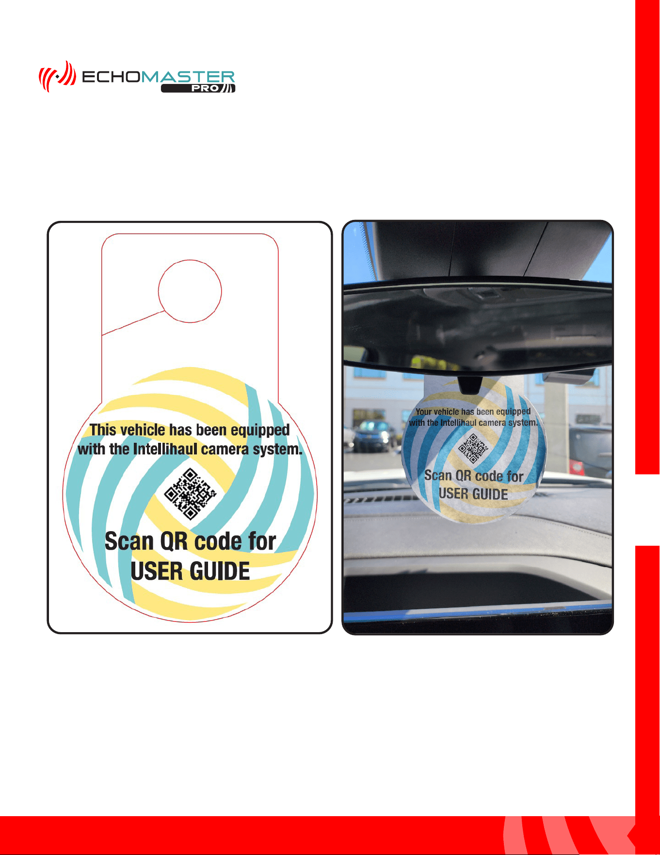
Mirror Hang Tag
After completeing the initial setup and verifying proper functionality, take the mirror hang tag (A.) with the User
Guide QR code on it and hang it from the rear view mirror, as shown in figure B, so that the customer is able
to scan the QR code to access the user guide.
A.
B.
v

AGREEMENT: End user agrees to use this product in compliance with the instructions and terms of use above and with
all State and Federal laws. EchoMaster provides instructions and safety warnings with respect to this product and
disclaims all liability for any use not in conformity with those instructions or other misuse of its product. If you do not agree,
please discontinue use immediately and contact EchoMaster. This product is intended for off-road use and passenger
use only.
email - gmsupport@echomaster.com
tel - 1-866-766-2267
15500 Lightwave Drive, Suite 202, Clearwater, Florida 33760
EchoMaster is a Power Brand of Stinger.
EchoMaster.com
REV. DC020624