Loading ...
Loading ...
Loading ...
18 BRIGGSandSTRATTON.COM
Initial Start-up (No Load)
Before operating the generator or placing it into service,
inspect the entire installation carefully. Familiarize yourself
with the location of components and the location and
function of the generator controller. Begin testing the system
without any electrical loads connected, as follows:
1. Check engine oil. Add oil if needed. Refer to engine
manual for type of oil required.
2. Set the generator main circuit breaker to OFF (open)
position.
3. Start the generator. When the generator is started
for the first time, air in the gaseous fuel lines will be
purged. This may cause the engine to run rough for a
few minutes.
4. Listen for unusual noises, vibration, or other
indications of abnormal operation. Check for oil and
coolant leaks while the engine runs.
5. Let the engine warm up for 5 minutes.
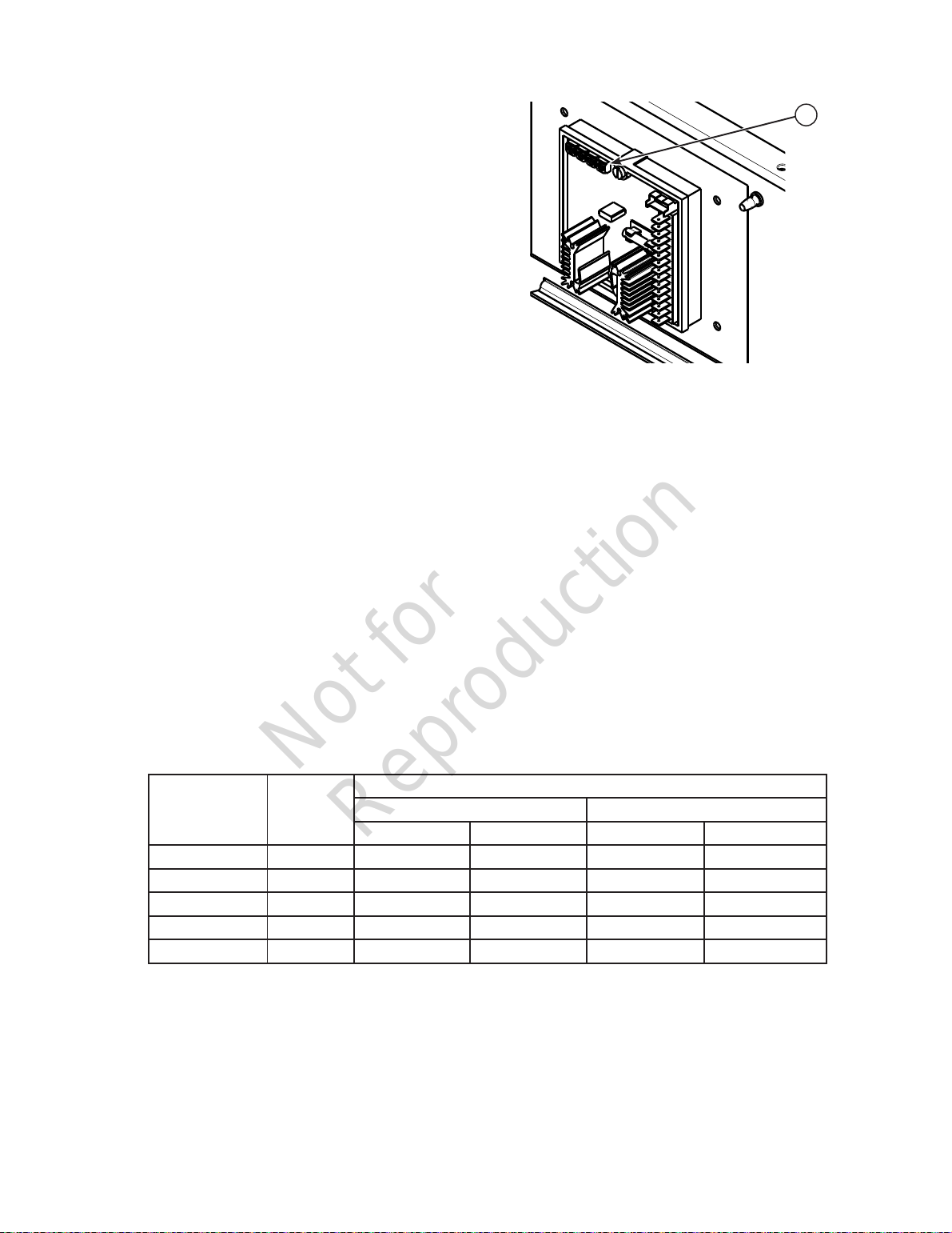
6. Check generator output at line side of circuit breaker.
No-load voltage should be as shown in the chart
below. Frequency should be 59.8 - 60.2 Hz.
NOTE
If the no-load voltage is outside the specified
range, perform the automatic voltage regulator (AVR)
adjustment in Step 8. Do not proceed until the AC
voltage is within the specified range.
7. Check voltage output between each of the circuit
breaker connection lugs and the neutral lug. No-load
voltage should be as shown in the chart below.
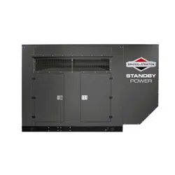
8. If necessary, adjust the AVR voltage control (A) to
obtain the range specified. DO NOT adjust any of the
other alternator controls.
9. Ensure that the transfer switch is in the "UTILITY"
position and that there is no load present on the
generator.
10. Set the generator main circuit breaker to ON
(closed) position.
11. Use a phase rotation meter to verify that output at the
load side of the circuit breaker matches utility power.
On high-leg delta systems, ensure that the high-leg
position of the generator matches the high-leg position
of the utility power.
12. Stop the generator.
A
Voltage
No-Load Voltage Table
Phase-to-Phase Phase-to-Neutral
Minimum Maximum Minimum Maximum
1-Phase 120/240 238 242 119 121
3-Phase Wye 120/208 206 210 119 121
3-Phase Delta 120/240 238 242 119 121
3-Phase Wye 277/480 475 485 275 279
3-Phase Wye 347/600 594 606 344 350
Not for
Reproduction
Loading ...
Loading ...
Loading ...