Loading ...
Loading ...
Loading ...
14 BRIGGSandSTRATTON.COM
Planning the Fuel Installation
The information provided below is intended to assist
gaseous fuel system technicians in planning installations.
State and local codes may override some of these
recommendations. Consult with the local fuel supplier or fire
marshall if clarification is needed.
WARNING
Propane
and Natural Gas are extremely
flammable and explosive, which could cause
burns, fire or explosion resulting in death or
serious injury.
• LP gas is heavier than air and will settle in low areas.
• Natural gas is lighter than air and will collect in
high areas.
• The slightest spark could ignite these fuels and cause
an explosion.
• DO NOT light a cigarette or smoke.
• A minimum of one accessible, approved manual
shutoff valve (F) shall be installed in the fuel supply
line within 6 ft (180 cm) of the generator.
• Where local conditions include earthquake,
tornado, unstable ground, or flood hazards, special
consideration shall be given to increase strength and
flexibility of piping supports and connections.
• Piping must be of the correct size to maintain the
required supply pressures and volume flow under
varying generator load conditions with all gas
appliances connected to the fuel system turned on
and operating.
• Use a pipe sealant or joint compound approved for
use with NG/LP on all threaded fittings to reduce the
possibility of leakage.
• Installed piping must be properly purged and
leak tested, in accordance with applicable codes
and standards.
The owner and installer should consult one another to review
any changes to the installation plan that might arise when
applying the following guidelines for fuel plumbing.
• The piping material must conform to federal and local
codes, be rigidly mounted, and be protected against
vibration.
• Piping should be protected from physical damage
where it passes through flower beds, shrub beds, and
other cultivated areas where damage could occur.
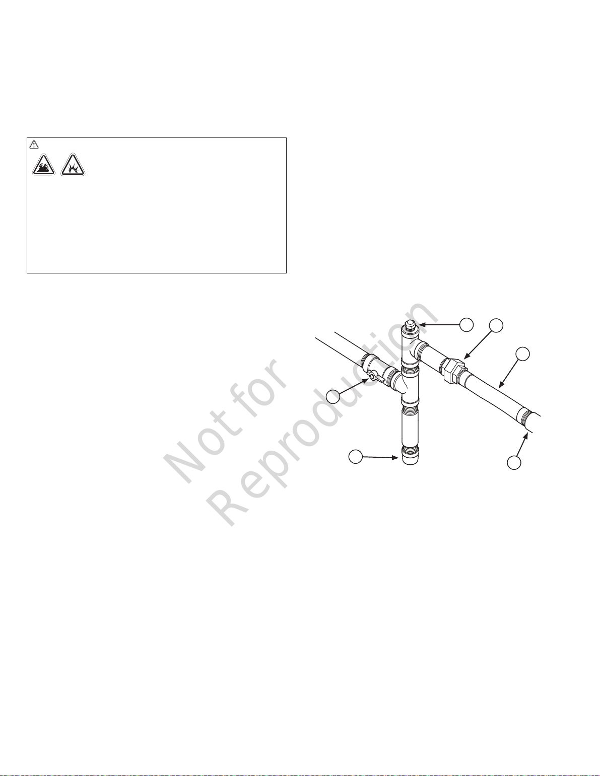
• Install a flexible hose (B, at right) between the
generator fuel inlet port (A) and the rigid piping to
prevent thermal expansion and contraction from
causing excessive stress on the piping material.
NOTICE
The flexible fuel pipe is not to be installed
underground or in contact with the ground. The entire flexible
gaseous pipe must be visible for periodic inspection.
• A union (C) or flanged connection shall be provided
downstream to permit removal of controls.
• A manometer test port (D) should be installed for
vapor fuels. The port permits temporary installation
of a manometer to check whether the engine is
receiving the correct fuel pressure to operate efficiently
throughout its operating range. A digital manometer
(P/N 19495) is available at your service center for
vapor fuels only. For liquid propane any pressure
measurement instrument rated for liquid propane and
350 psi can be used. When the initial test runs are
completed, the manometer is removed and the port is
plugged.
• For vapor fuels only: Where the formation of hydrates
or ice is known to occur, piping should be protected
against freezing. The termination of hard piping should
include a sediment trap (E) where condensate is not
likely to freeze.
A
B
C
D
E
F
A - Generator Fuel Inlet
B - Flexible Fuel Hose
C - Union Fitting
D - Manometer Test Port
E - Sediment Trap (Vapor Fuels Only)
F - Manual Shut-off Valve
Fuel Pipe Sizing
NFPA 54 and 58 are common resources. The installer
should consider the specific gravity of gas, compensate for
a nominal amount of restriction from bends and fittings, and
refer to federal and local codes for guidance.
Not for
Reproduction
Loading ...
Loading ...
Loading ...