
Technical Support and E-Warranty Certificate www.vevor.com/support
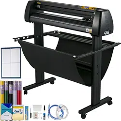
CUTTING PLOTTER
We continue to be committed to provide you tools with competitive price.
"Save Half", "Half Price" or any other similar expressions used by us only represents an
estimate of savings you might benefit from buying certain tools with us compared to the major
top brands and does not necessarily mean to cover all categories of tools offered by us. You
are kindly reminded to verify carefully when you are placing an order with us if you are
actually saving half in comparison with the top major brands.

1
Model : 720series,870series,1350series
Have product questions? Need technical support? Please feel free to
contact us:
Technical Support and E-Warranty Certificate
www.vevor.com/support
NEED HELP? CONTACT US!
This is the original instruction, please read all manual instructions
carefully before operating. VEVOR reserves a clear interpretation of our
user manual. The appearance of the product shall be subject to the
product you received. Please forgive us that we won't inform you again if
there are any technology or software updates on our product.
CUTTING PLOTTER

2
Ⅰ.Bacic Safety Rules
WARNING:Read all safety warnings, instructions, illustrations and
specifications provided with this appliance. Failure to follow all instructions listed
below may result in electric shock, fire and/or serious injury.
1.Protective material must be removed before turning on the cutting plotter.
2.Check the label on the back side of the plotter to confirm that the rated voltage
required by the plotter matches the voltage of the power base.
3.Firstly make sure that the power switch is off, then plug the power supply into
grounded power outlet.
4.Do not operate any appliance with a damaged cord or plug or after the appliance
malfunctions, or has been damaged in any manner. Return appliance to the
nearest authorized service facility for examination, repair or adjustment.
5.Type X attachment: If the supply cord is damaged, it must be replaced by a
special cord or assembly available from the manufacturer or its service agent.
6.Please do not touch the power cord with wet hands to avoid electric shock.
7.Please only use the power cord, data cable provided with this product, or
manufacturer-approved replacements.
8.Do not use outdoors. INDOOR USE ONLY
9.Please do not drop metal objects and liquids into the machine to avoid
malfunction.
10.After shutting down, you must wait another 5 seconds to turn on the cutting
plotter again, otherwise it will cause damage to the cutting plotter.
11.In thunderstorms, turn the power switch to OFF and unplug the power cord.
12.Please do not privately change the manufacturer's components.
13. Manufacturer reserves the right to change product specifications without prior
notice.
14.The manufacturer only bears the legal obligations of the product itself sold to
the users, and does not bear other losses caused by the malfunction of the
products.
15.Without our company’s permit, no part of this manual can be copied or
transmitted in any name.
3
16.Do NOT drag the carriage by hand.
17.If there is an abnormal sound after powering on the machine, please turn off the
power immediately and contact the after-sales department for feedback.
18.This appliance can be used by children aged from 8 years and above and
persons with reduced physical, sensory or mental capabilities or lack of
experience and knowledge if they have been given supervision or instruction
concerning use of the appliance in a safe way and understand the hazards
involved. Children shall not play with the appliance. Cleaning and user
maintenance shall not be made by children without supervision.
19.Close supervision is necessary when any appliance is used by or near children.
Children shall not use the appliance. Cleaning and user maintenance shall not be
made by children.
20.To protect against fire, electric shock, or personal injury, do not immerse cords,
electric plugs, or appliances in water or other liquids.
21.WARNING:
Blade is very sharp.Please do not touch the blade directly with your
hand, otherwise, your finger will be injured and the tip will be blunt. and hold the
arbor on the blade when you remove it.
Ⅱ.Matters needing attention
To ensure that the operator can correctly use the plotter to prevent damage to the
plotter, please follow the instructions with the following marks.
1.Ensure safe use methods
warning
Improper operation can result in injury.
Improper operation may cause damage to the
machine.
Pay attention to
Improper operation may result in personal injury or
damage to other objects.
4
2.Symbol Description
warning
Symbol indicates that users need to pay close attention. The picture on
the left means "Be careful of electric shock".
Do not use a power supply that does not meet the rated voltage.
Using an unqualified power supply can cause fire or electric shock.
If the machine gives out smoke, smell, noise and other abnormal
circumstances, please power off immediately, do not use.
Use in this condition can cause fire or electric shock.
Do not plug or remove the power plug when the power is on.
Unplugging the power plug while the power is on will damage the
machine.
Ensure machine grounding.
Electrical shock or mechanical failure if not grounded.
Do not disassemble, repair or rectify the machine.
Do like this will result in fire or electric shock, resulting in personal injury.
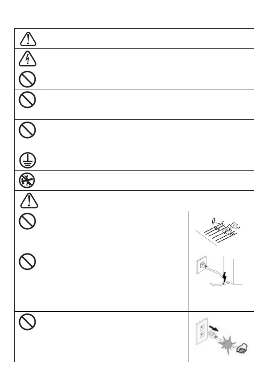
Pay attention to
The machine can not penetrate into liquids,
fall into metal objects, etc.
These objects can cause fires.
Do not destroy or replace the original power
cord, and do not allow the power cord to be
excessively bent, pulled, tied or pressed
under heavy objects.
Do like this could damage the power supply,
cause an electric shock or cause a fire.
If the cutting plotter will not be used for a
long time, please unplug the power cord from
the socket.
Otherwise it will cause a fire.
5
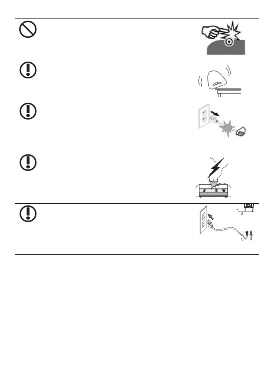
When operating, do not put your hands on
the reel.
This may cause injury.
The machine should be placed on a stable
surface.
Otherwise the machine will fall, resulting in injury.
When unplugging the power cord from the
socket, the plug should be pulled, not the
cable.
Pulling on the cable can cause electric shock or
fire.
It is prohibited to use in thunderstorms and
lightning weather.
To avoid lightning damage to the machine.
Before inserting the power plug, check
whether the power supply voltage and power
cable are normal.
Make sure there are no exceptions before you
plug in the device.

6
Contents
Ⅰ.Precautions……………………………....................................2
Ⅱ. Introduction for main parts………………........................…...3-6
Ⅲ. Technical parameters………….…........................................7-8
Ⅳ. Bracket assembly diagram……..………….......................….9-12
Ⅴ.Blade assembly……..............................................................13-15
Ⅵ. How to use the product….....................................................16-23
Ⅶ.How to connect products to software.....................................24
Ⅷ. Software and driver installation….........................................25-30
Ⅸ. Connection of software and machine…................................31-34
Ⅹ.Troubleshooting.....................................................................35-37

7
Ⅰ. Precautions
1. Protective material must be removed before turning on the cutting plotter.
2. Check the label on the back side of the plotter to confirm that the rated
voltage required by the plotter matches the voltage of the power base.
3. Firstly make sure that the power switch is off, then plug the power supply
into grounded power outlet.
4. Please do not touch the power cord with wet hands to avoid electric shock.
5. Please only use the power cord, data cable provided with this product, or
manufacturer-approved replacements.
6. Please do not drop metal objects and liquids into the machine to avoid
malfunction.
7. After shutting down, you must wait another 5 seconds to turn on the cutting
plotter again. Otherwise, it will cause damage to the cutting plotter.
8. In thunderstorms, turn the power switch to OFF and unplug the power cord.
9. Please do not privately change the manufacturer's components.
10. Manufacturer reserves the right to change product specifications without
prior notice.
11. The manufacturer only bears the legal obligations of the product itself sold
to the users, and does not bear other losses caused by the malfunction of the
products.
12. Without our company’s permit, no part of this manual can be copied or
transmitted in any name.
13. Do NOT drag the carriage by hand.
14. If there is an abnormal sound after powering on the machine, please turn
off the power immediately and contact the after-sales department for
feedback.
8
Ⅱ. Introduction for main parts
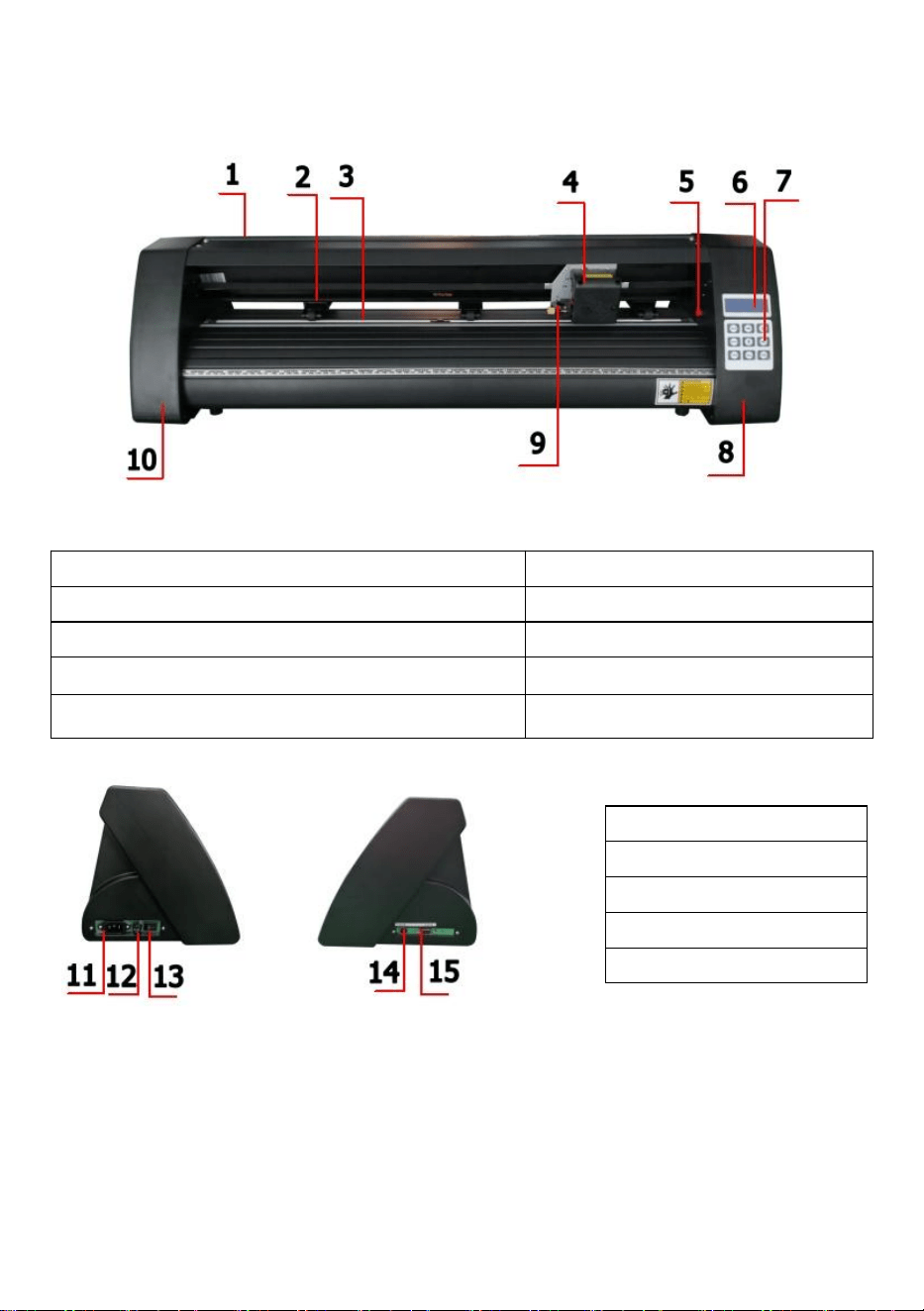
KH Model
Left side Right side
1.Cover for rail guide
2. Pinch roller kit
3. Roller for feeding paper
4. Carriage
5. Reset switch
6. Screen
7. Buttons
8. The right cover
9. Blade clamp
10. The left cover
11.Power connection
12.Fuse holder
13.Power switch
14.USB port
15.COM port
9
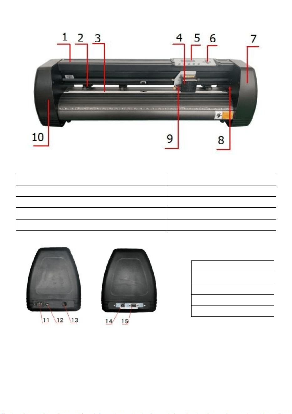
KI Model
Left side Right side
1.Cover for rail guide
2. Pinch roller kit
3. Roller for feeding paper
4. Carriage
5. Screen
6. Buttons
7. The right cover
8. Reset switch
9. Blade clamp
10. The left cover
11.Power connection
12.Fuse holder
13.Power switch
14.USB port
15.COM port
10
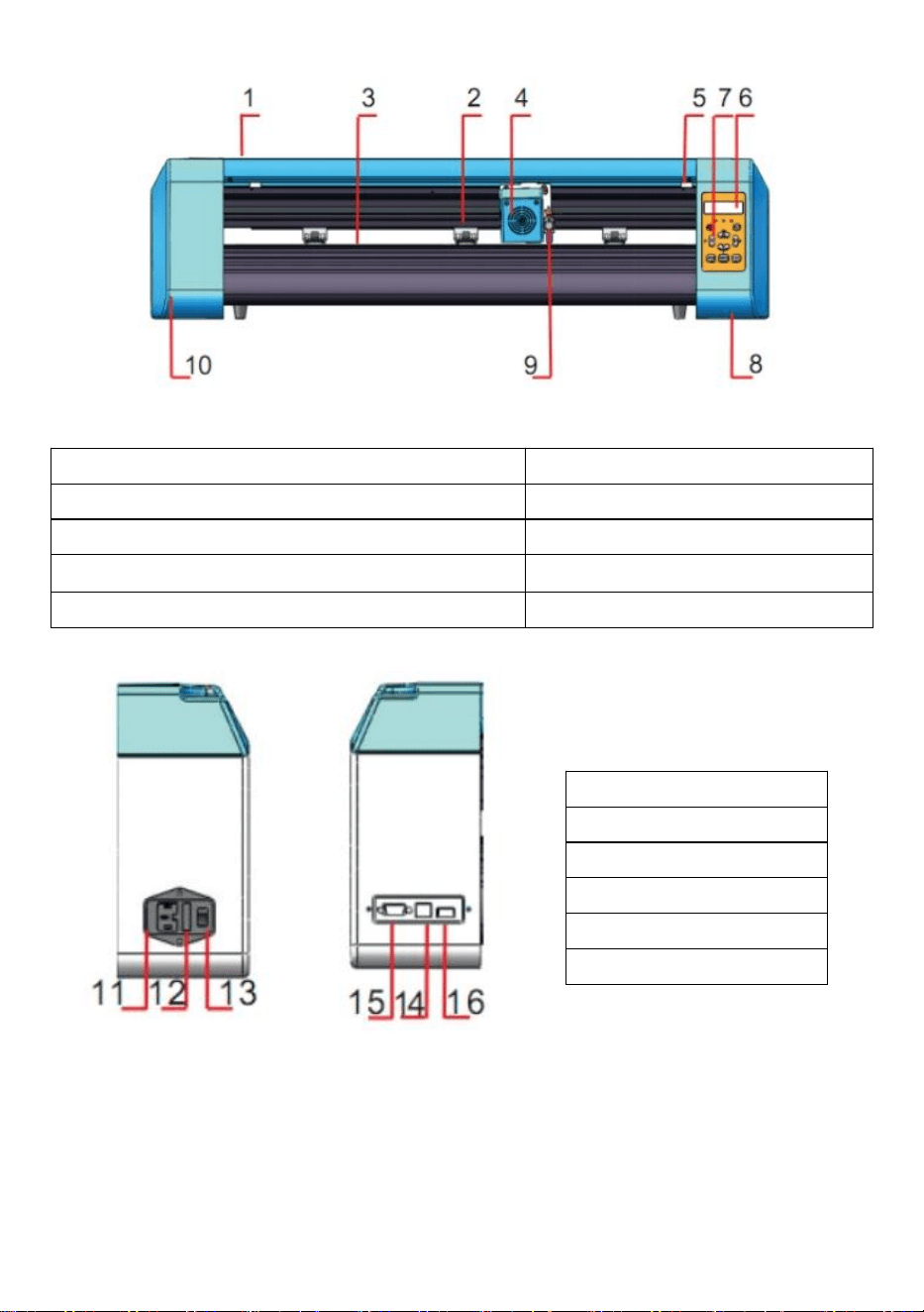
EH Model
Left side Right side
1.Cover for rail guide
2. Pinch roller kit
3. Roller for feeding paper
4. Carriage
5. Reset switch
6. Screen
7. Buttons
8. The right cover
9. Blade clamp
10. The left cover
11.Power connection
12.Fuse holder
13.Power switch
14.USB port
15.COM port
16.U-disk port
11
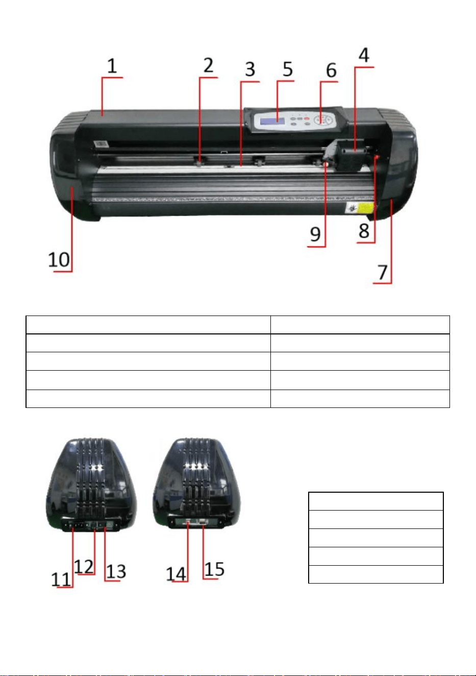
SK Model
1.Cover for rail guide
2. Pinch roller kit
3. Roller for feeding paper
4. Carriage
5. Screen
6. Buttons
7. The right cover
8. Reset switch
9. Blade clamp
10. The left cover
Left side Right side
11.Power connection
12.Fuse holder
13.Power switch
14.USB port
15.COM port

12
Ⅲ. Technical parameters
Model
Item
720
870
1350
Max. feeding width
720mm
870mm
1350mm
Max. cutting width
615mm
765mm
1245mm
Cutting thickness
≤1mm
Speed/Pressure
20-800mm/s 20-500g
Buffer
1-4M
LCD display
CN/EN
Real-time
Speed adjusting
Support
Interface
COM+USB / COM+USB+U-DISK
Re-cutting function
Support
Re-cutting accuracy
±0.1mm
Language format
DMPL/HPGL
Voltage
AC85-264V,50/60Hz,MAX100W

13
Accessory box
Item
Quantity
Unit
1
Cutting plotter
1
Set
2
Power supply cable
1
Pc
3
Blade
1
Box
4
Blade holder
1
Pc
5
Pen holder
1
Pc
6
Ball pen core
1
Pc
7
COM connection cable
1
Pc
8
USB cable
1
Pc
9
Spanner
1
Pc
10
USB driver
1
Pc
11
Bracket screws
1
Bag
To protect the machine, use only the accessories in this accessory box
14
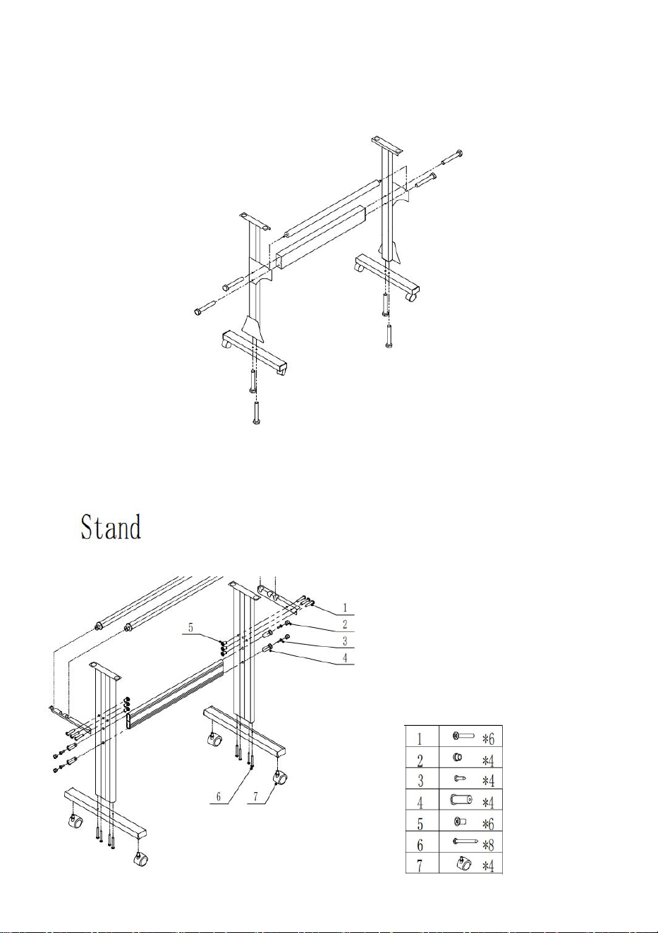
Ⅳ. Bracket assembly diagram
1-1 Iron bracket assembly diagram
1. M6*40 Hex bolts 8pcs
1-2 Al bracket assembly diagram
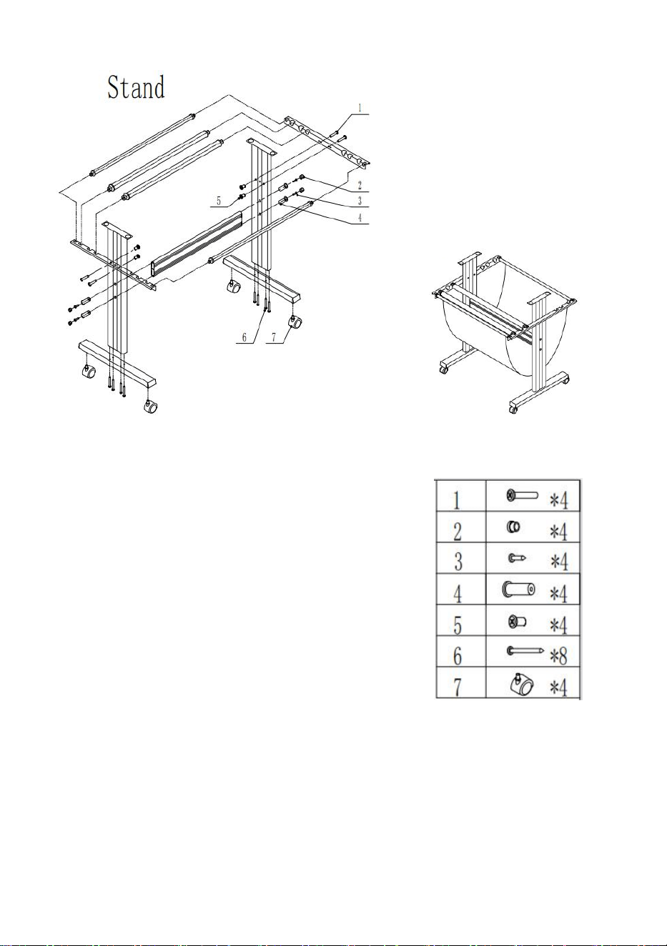
15
1-3 Sheet metal racket assembly diagram
16
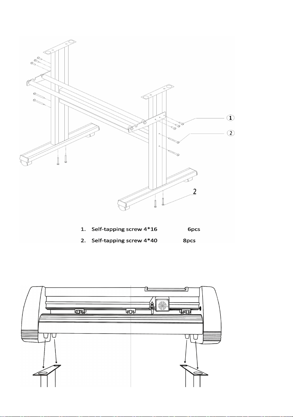
1-4 AI bracket assembly diagram
2-1 Install the machine on the bracket
17
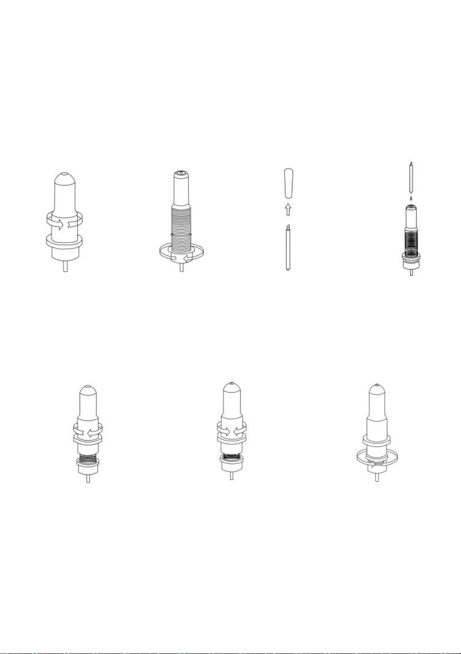
Ⅴ. Blade assembly
1 Unscrew the cap
from the blade
carriage.
2 Set the brass
ring on the blade
carriage to the
fully down
position.
3 Remove the
protective cover
from a new blade.
4 Insert the blade
into the top of the
blade carriage.
5 Screw the cap back
onto the blade carriage.
6 Adjust the carriage cap
until the blade is
protruding approximately
1/64 of an inch.
7 Adjust the brass ring
until it fits snugly against
the cap. This will help
keep the cap in place
during operation.
Blades should be replaced every 6 months. Your blade may need to be replaced
more often if you are cutting thicker material, such as flock, glitter, or reflectives.
18
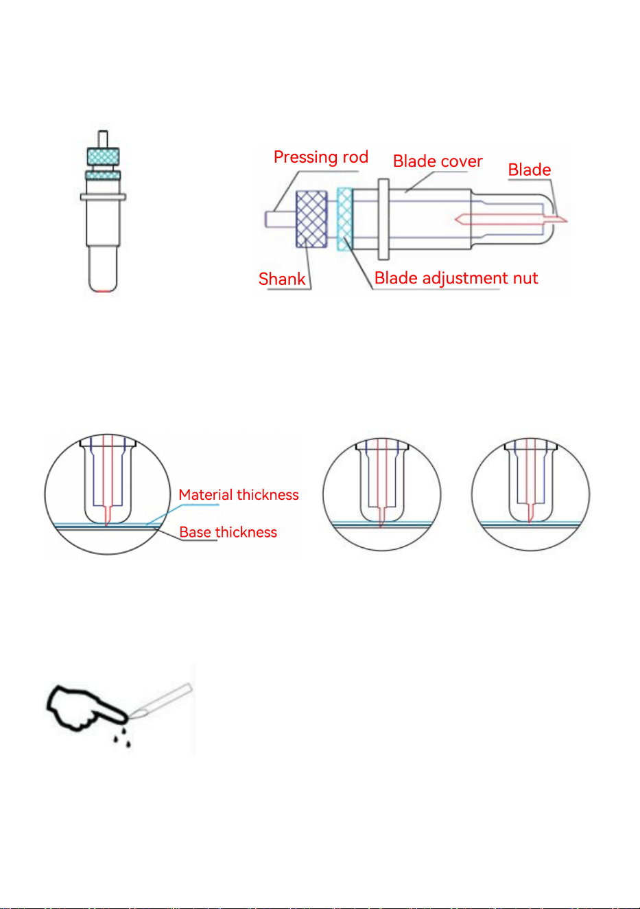
1) . Assemble the blade into the holder. See as below:
(Appearance view) (Exploded view)
2). Loosen the blade adjustment nut and rotate the shank to adjust the length of
the exposed blade tip. Determine the tip length according to the thickness of the
material.
Correct Blade tip is too long Blade tip is too short
3)Press the pressing rod when you want to change the blade. Take out the blade
when it is exposed.
Tips:
Do not touch the blade tip by finger. Otherwise, your finger will be injured and the
tip will be blunt.
19
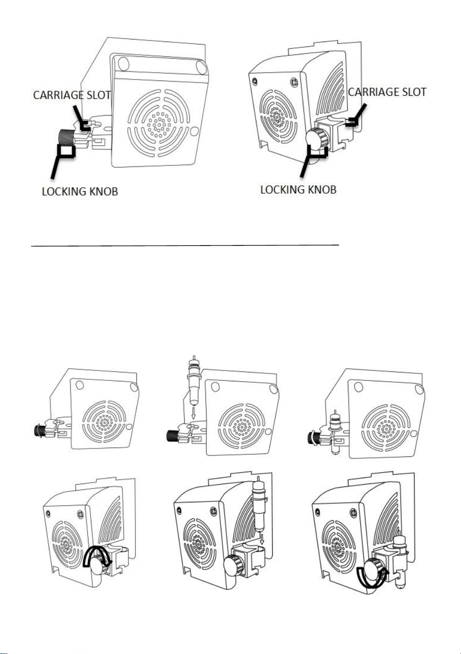
CARRIAGE SLOT Holds the blade carriage in place.
LOCKING KNOB
Allows access to the blade/pen carriage slots for
exchanging/replacing carriages.
1 Loosen the locking knob
on the carriage arm.
2 Place the blade carriage
into the carriage arm.
3 Tighten the locking knob
on the carriage arm.

20
Ⅵ.How to use the product
KI Model
SK Model
EH Model KH Model
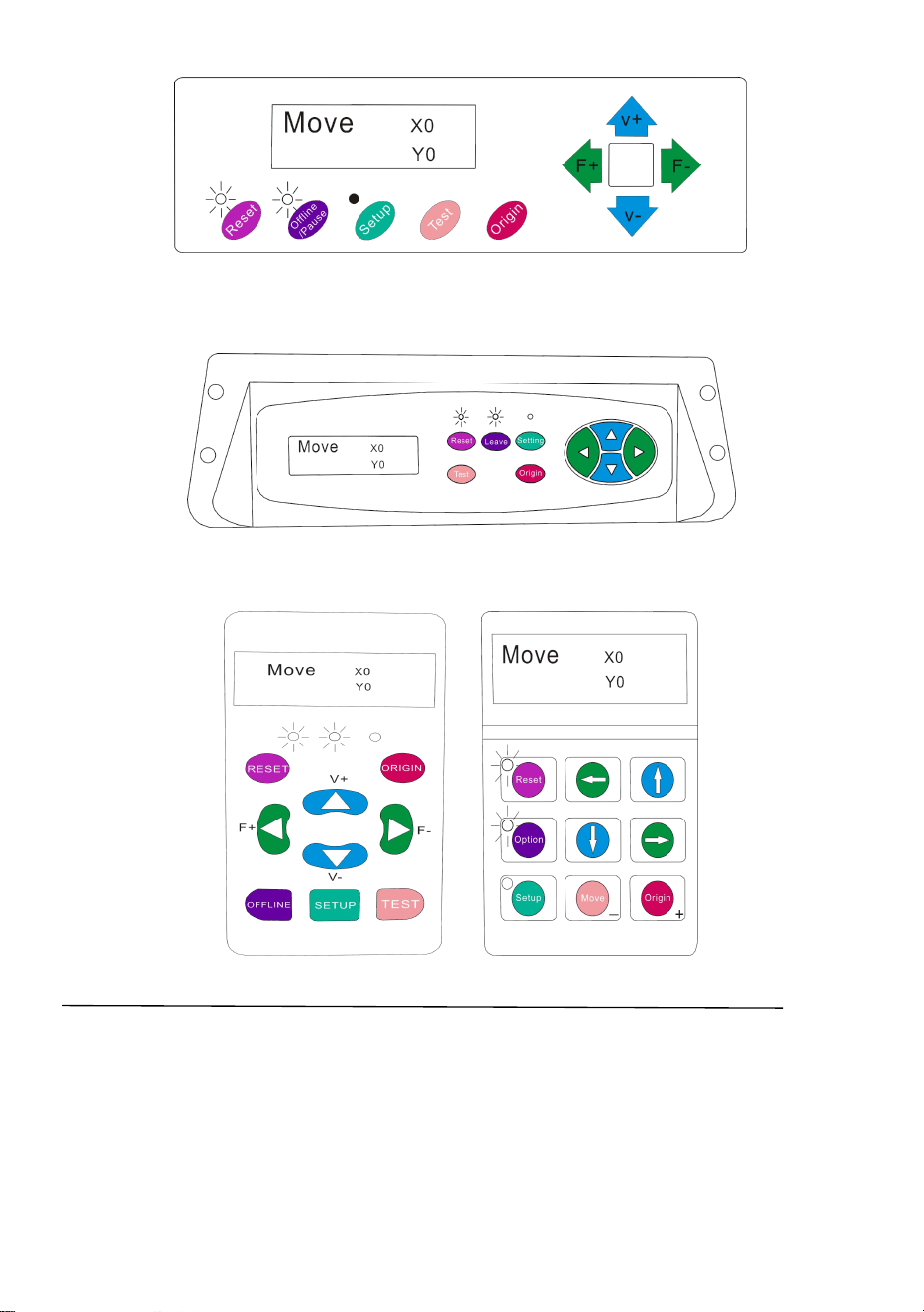
The main screen of the cutter allows you to set the main settings of the cutter
including the cutting speed and cutting force options. It also allows you to cut a test
pattern or check the amount of force that is currently set.

21
Reset BUTTON
Resets by stopping the cutter, and setting the
origin of the carriage arm to its rightmost
position.
Offline/Leave/Option BUTTON
Accesses the Offline/Pause mode.
SETUP BUTTON
Accesses the Setup mode.
TEST/Move BUTTON
Will cut a small test shape so that the current
force and speed settings of the cutter can be
tested. You can use this to determine the proper
cutting speed and force settings needed for
different materials without wasting large
amounts of material from cutting full designs.
ORIGIN BUTTON
Used to test z-axis functionality (by dropping the
blade down if the carriage is functioning
properly) or to set a new origin point when the
machine is in its Offline mode
V+ / V- BUTTONS
Adjusts the cutting speed. A cutting speed of 300
mm/s is a reasonable default speed that can be
used for most cuts. When working with smaller
and more detailed images, a slower speed may
be required. When working with larger and less
detailed images, a higher speed can be used to
shorten the operation time.
F+ / F- BUTTONS
Adjusts the cutting force. A cutting force of 100g
is a good general starting place to work from
when trying to determine the force needed for a
specific material. All cuttable materials
will differ in the amount of force needed so
proper testing should always be made to
determine the amount of force to use. The
amount of force used should be enough to fully
penetrate the
material to be cut while not enough to cut
through the backing material.
22
KI Model
SK Model
EH Model KH Model
Offline mode is used to reposition the cutting material and blade so that a new
starting position can be set for the next design. Offline mode can also be accessed
while the cutter is in operation and will pause the current cutting process. Although
changes can be made to the material and blade positions if Offline /Pause mode is
accessed during cutting, making changes to either setting is not normally
recommended.

23
Reset BUTTON
Resets by stopping the cutter, and setting the
origin of the carriage arm to its rightmost
position.
Offline/Leave/Option BUTTON
Ignores any changes that have been made to
the material or blade positions and exits
Offline/Pause mode, returning the cutter to the
main screen. Resumes any cutting that was
taking place when Offline/Pause mode was
entered.
SETUP BUTTON
Has no function in this mode.
TEST/Move BUTTON
Accepts any changes that have been made to
the material or blade positions and exits Offline
/Pause mode returning the cutter to the main
screen. Resumes any cutting that was taking
place when Offline /Pause mode was entered
from the new blade/material positions.
ORIGIN BUTTON
Accepts any changes that have been made to
the material or blade positions and exits Offline
/Pause mode returning the cutter to the main
screen. Resumes any cutting that was taking
place when Offline /Pause mode was entered
from the new blade/material positions.
V+ / V- BUTTONS
Reposition the material by moving the feed
rollers. After movements are made, you can
confirm the changes by pressing the TEST or
ORIGIN buttons or cancel by pressing the
OFFLINE/PAUSE button.
F+ / F- BUTTONS
Reposition the blade by moving the carriage
arm. After movements are made you can
confirm the changes by pressing the TEST or
ORIGIN buttons or cancel by pressing the
OFFLINE/PAUSE button.
24
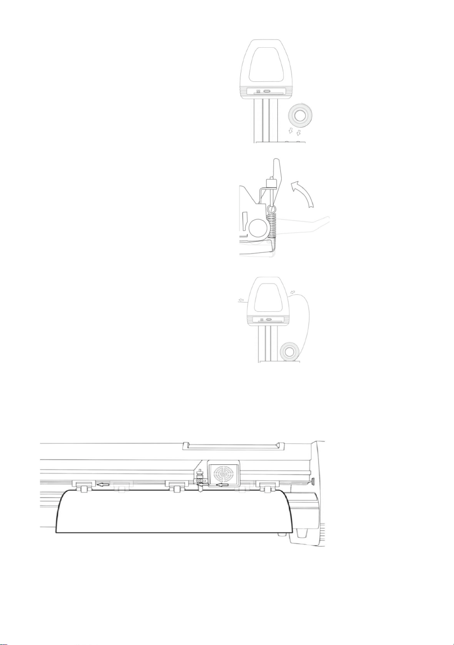
1. Place the roll on top of the stand
rollers.
For heat press vinyl, please flip the roll.
2. Release the pinch rollers release
levers.
3. Feed the vinyl underneath the pinch
rollers (if working from a single sheet
instead of a roll, the vinyl can also be
fed from the front).
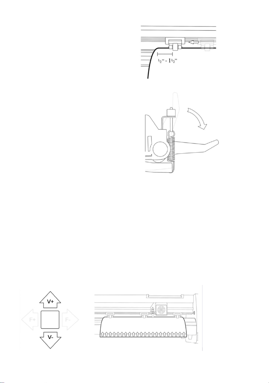
4. Adjust the pinch rollers so there is one roller located on each side of the vinyl
(and, on models with 3 or more rollers, one roller near the center). Avoid lowering a
pinch roller to the gap between the two feed rollers.
25
5. Leave a gap of between1/2”-1 1/2”
from the edge of the roller and the edge
of the vinyl on both sides.
6. Engage the Pinch Rollers by pushing
down on the Pinch Roller Release
Levers.
If the cutter is not already on, turn it on now.
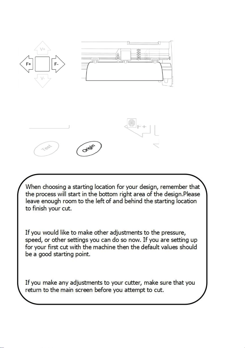
If you would like to change the position of where the cut will
be made:
1. Press the OFFLINE/PAUSE button to enter offline mode.
2. Adjust the vinyl to where you want to make your cut to start by using the Up and
Down arrow keys on the control panel.
26
3. Now, adjust the blade to where you want your cut to start by using the Left and
Right arrow keys.
4. Now press the Origin button to tell the cutter that this is the location where you
would like the cut to begin.

27
Ⅶ How to connect products to software
Attach the power cord to the cutter and then plug in the unit and turn on the power.
INSTALLING VINYL MASTER SOFTWARE
It comes bundled with SignMaster software, an easy-to-use software with the tools
to help you take your projects from concept to a ready-to-cut computer image file.
The driver is automatically installed during software installation. You do not need to
install the driver separately.
Ⅷ. Software and driver installation
1. Open the software box (pic 1), take the disk and put it into CD optical drive
( pic 2)
(pic 1) (pic 2)
28
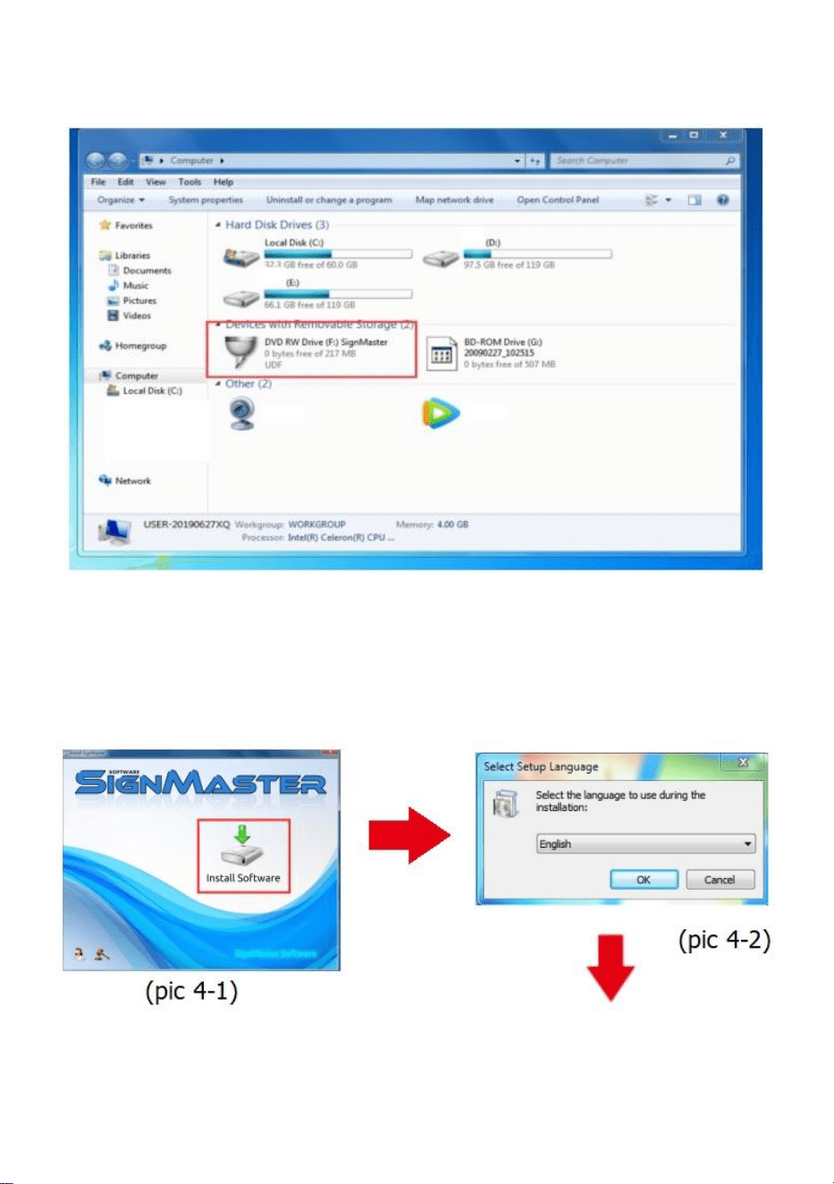
2. Open the computer, double click or right click optical drive to install the software.
(pic 3)
(pic 3)
3. After opening optical drive, click Install Software (pic 4)
Click on the icon in the red box
Select the language
29
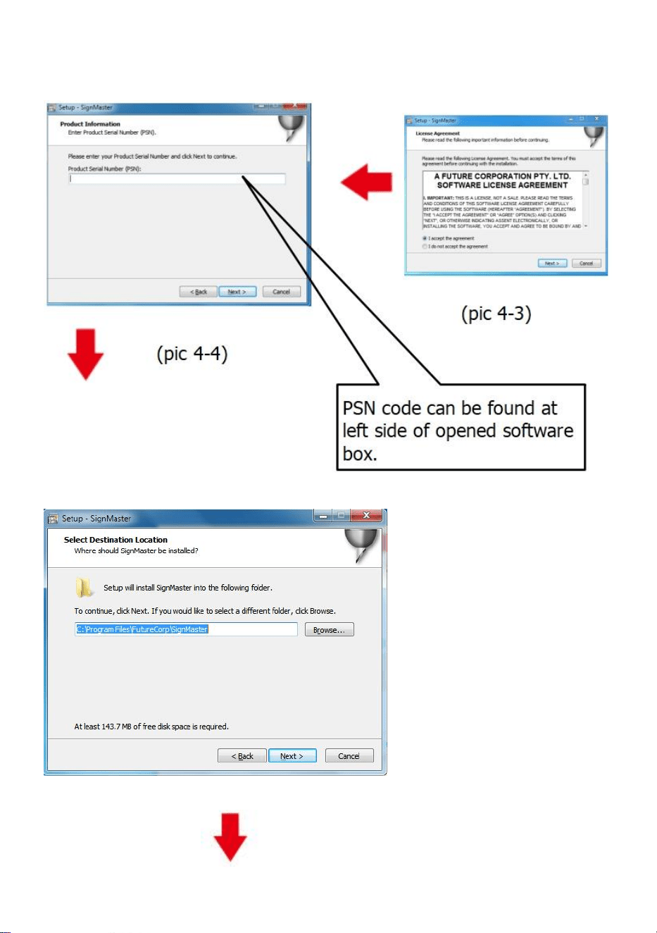
Enter the PSN code
Agree to click next
Default installation path, click next
(pic 4-5)
30
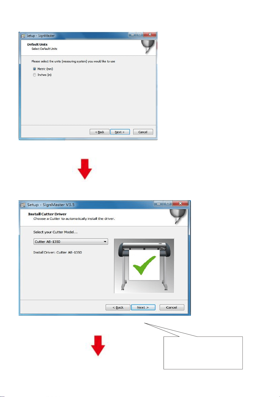
Select the unit
(pic 4-6)
Select machine model
(pic 4-7)
T h e selected m ach ine
m odel can b e view ed
in th e lab el ab o ve th e
m ach ine p ow er so cket
31
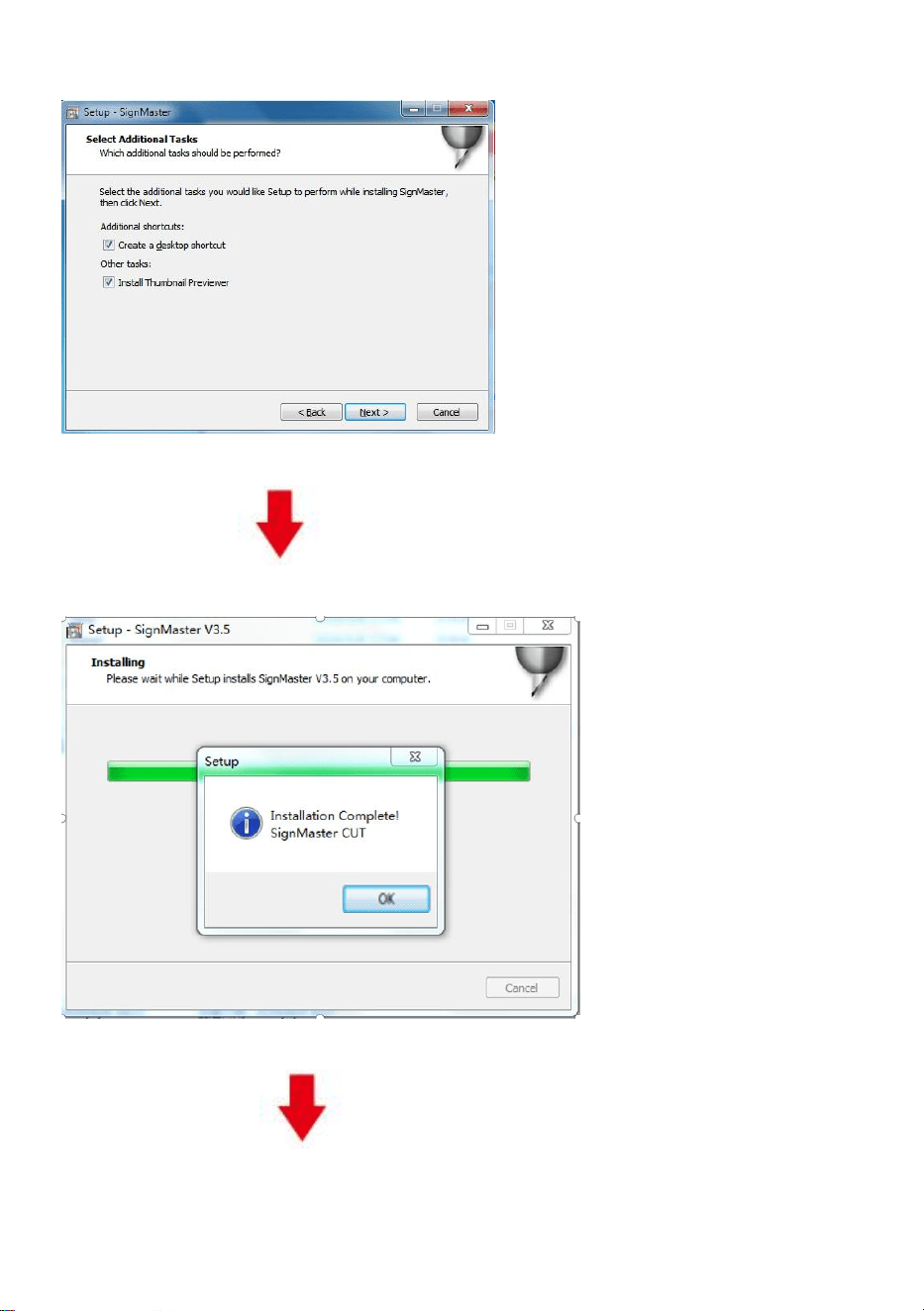
Next
(pic 4-8)
The installation is complete
(pic 4-10)
32
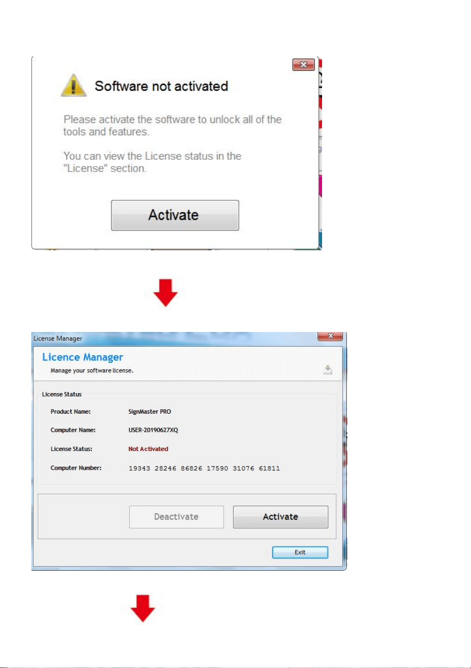
This activation window appears when you open the software
(pic 4-11)
Click activate and enter your email twice
(pic 4-12)
33
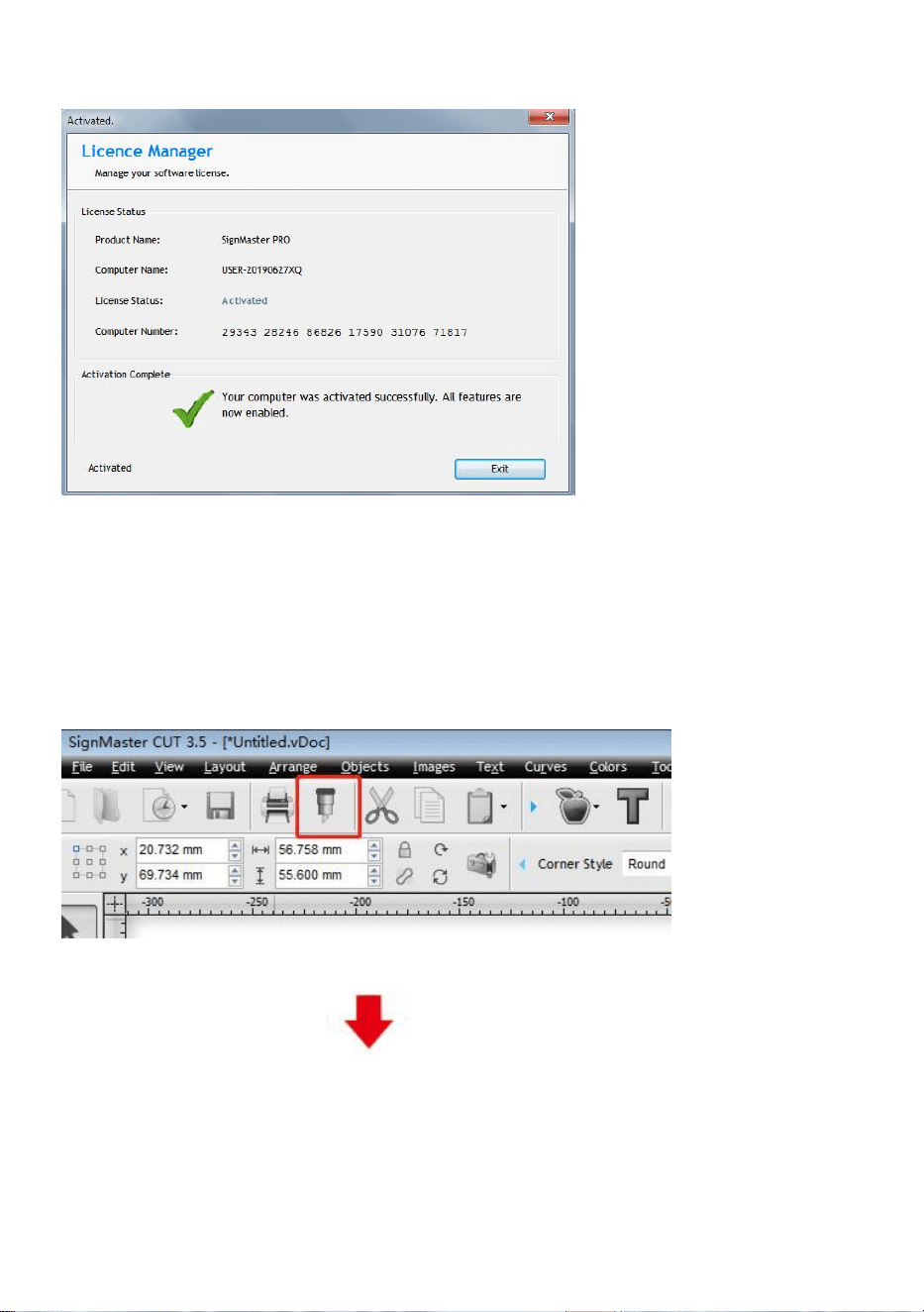
Activation successful, exit
(pic 4-13)
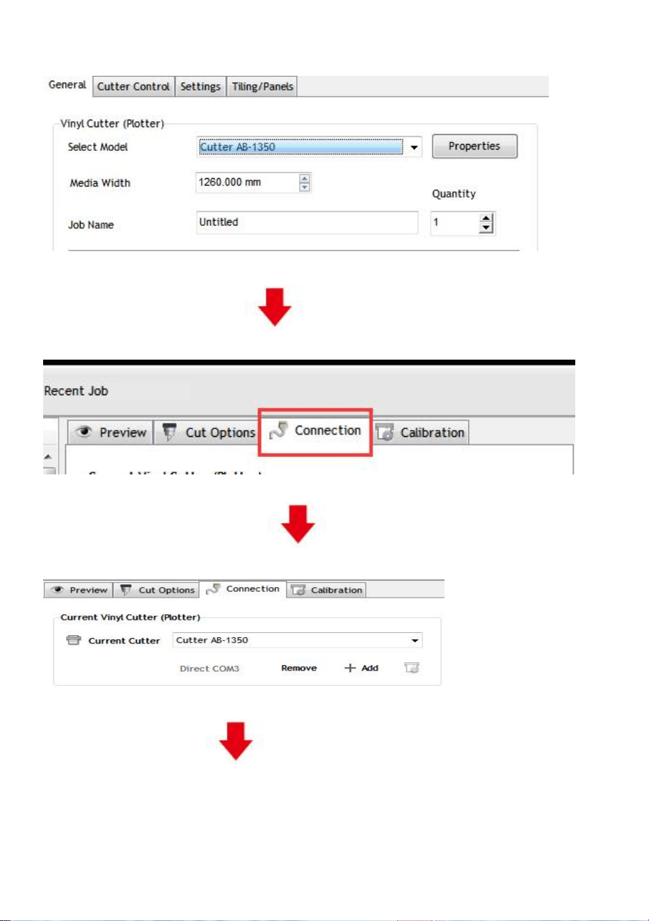
Ⅸ. Connection of software and machine
1.Open the software, select cut content, and click send to the cutting plotter
Click the cutter icon in the red box
(pic 5-1)
34
Click properties
(pic 5-2)
Click connect
(pic 5-3)
Select machine model
(pic 5-4)
Select Direct USB Port
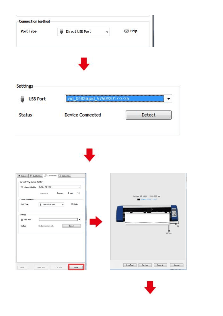
35
(pic 5-5)
Drop-down select driver
(pic 5-6)
Click finish
Click cut now
(pic 5-7) (pic 5-8)
36
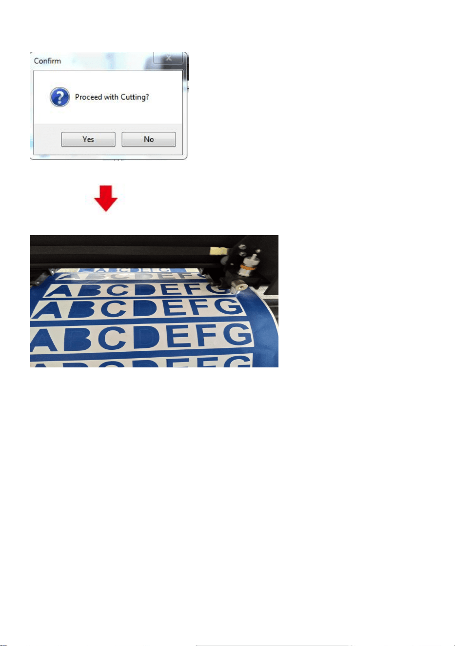
Click cut now
(pic 5-9)
The output is completed, the cutting plotter is cutting
(pic 5-10)
Note: Specific operation can refer to USB flash drive operation video, including as
follows
1. Ordinary cutting video
2. Automatic contour video
3. Automatic deviation correction video
4. Software installation video
Ⅹ.Troubleshooting
1.The computer does not have the CD drive cannot load the CD installation
software how to do.
37
Solution: The software installation package is included in the usb flash drive. You can also
download the software from the following
link:https://fcws6.com/downloads/signmaster/SignMaster_UniverDSR_35_GW.exe
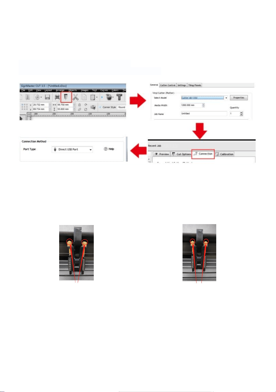
2. Product cannot connect to software.
Solution:Software port Settings, as shown below:
3.Paper deviation occurred during cutting.
Solution: Because the tension of paper press is inconsistent, rotate the two yellow
copper nuts on each paper press to the same height, then the pressure is
balanced, as shown below:
High inconsistency
Rotate to the same height
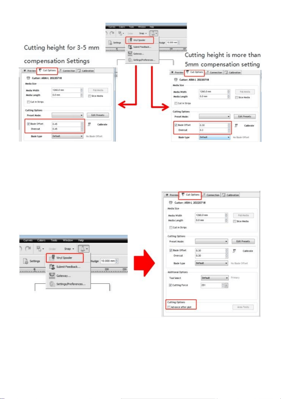
4.The effect of small graphics cutting is not ideal.
Solution: When the cutting height is 3-5 mm letters, the software compensation
value is set to 0.45 and the speed is adjusted to 400mm/s. When the cutting height
is more than 5 mm letters, the software compensation value is set to 0.3 and the
speed is adjusted to 600mm/s or more.
38
5.Often repeated cutting, cutting before automatic paper and other problems.
Solution: Cancel the automatic paper feeding function after cutting in the software,
as shown below:
6.The cutting process stops and does not return to the origin.
Solution:Do not use any data conversion connector. Data may be lost and the
cutting process may stop. Please plug the data line directly into the computer
interface.

39
FCC Information
CAUTION: Changes or modifications not expressly approved by the party
responsible for compliance could void the user's authority to operate the
equipment!
This device complies with Part 15 of the FCC Rules. Operation is subject to the
following two conditions:
1) This product may cause harmful interference.
2)This product must accept any interference received, including interference that
may cause undesired operation.
WARNING: Changes or modifications to this product not expressly approved by
the party.responsible for compliance could void the user's authority to operate the
product.
Note: This product has been tested and found to comply with the limits for a
Class B digital device pursuant to Part 15 of the FCC Rules, These limits are
designed to provide reasonable protection against harmful interference in a
residential installation.
This product generates, uses and can radiate radio frequency energy, and if not
installed and used in accordance with the instructions, may cause harmful
interference to radio communications. However, there is no guarantee that
interference will not occur in a particular installation. If this product does cause
harmful interference to radio or television reception,which can be determined by
turning the product off and on, the user is encouraged to try to correct the
interference by one or more of the following measures.
· Reorient or relocate the receiving antenna.
· Increase the distance between the product and receiver.
· Connect the product to an outlet on a circuit different from that to which the
receiver is connected.
· Consult the dealer or an experienced radio/TV technician for assistance.

40
VIIII CORRECT DISPOSAL
This product is subject to the provision of European Directive 2012/19/EC.
The symbol showing a wheelie bin crossed through indicates that the product
requires separate refuse collection in the European Union. This applies to the
product and all accessories marked with this symbol. Products marked as such
may not be discarded with normal domestic waste, but must be taken to a
collection point for recycling electrical and electronic devices.
Address:Shuangchenglu 803nong11hao1602A-1609shi, baoshanqu,
shanghai 200000 CN.
Imported to AUS: SIHAO PTY LTD, 1 ROKEVA STREETEASTWOOD
NSW 2122 Australia
Imported to USA: Sanven Technology Ltd., Suite 250, 9166 Anaheim
Place, Rancho Cucamonga, CA 91730
REPUK
YH CONSULTING LIMITED.
C/O YH Consulting Limited Office 147, Centurion House,
London Road,
Staines-upon-Thames, Surrey, TW18 4AX
REPEC
Made In Chin
E-CrossStu GmbH
Mainzer Landstr.69, 60329
Frankfurt am Main.
a