Loading ...
Loading ...
Loading ...
14
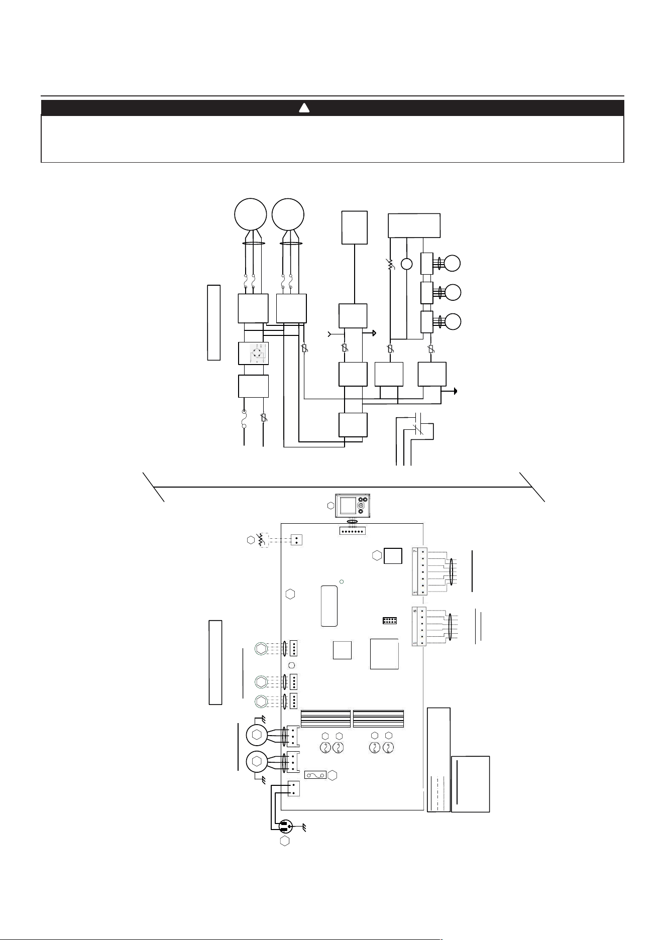
4. WIRING DIAGRAM
BL
K
B
LK
GRN
LOGIC DIA
GRAM
W
IRIN
G C
OL
O
R C
ODE
BLK BLA
CK
BLU BLU
E
GR
N GR
EE
N
RED RED
WHT
W
HITE
Line
vo
ltag
e
fact
or
y
wir
ing
Low vo
ltag
e fa
cto
ry
wirin
g
Low
vo
ltag
e fie
ld wir
in
g
(Exhaus
t
)
B
LU
R
ED
120VAC
60Hz
W1
GRN
F1
1
Power
LE
D
J1
M2
Damp
er
Stepp
er
M
ot
or
s
Y
M1
W
HT
BLK
A1
MAIN EL
E
CTRO
NIC
ASSEMBLY
M1
Po
wer
Sup
ply
(15
V
DC
)
Line
Neut
ral
K1
G
Gf
AC
Line
Fi
lter
J1-2
F1
High
Voltag
e
(120VAC
)
J1-1
To J
2
MC
U
K1
M3
St
epp
er
Dr
iver
To
J
5
WIRING DIA
GRAM
BDM
1
5A
/12
5V
AC
J
2 J
3
J5 J6
J7
1
1
1
1
1
J7a
J15a
1
A2
LC
D
AS
SE
M
B
LY
GR
N
Ve
ntilatio
n
Fa
n Moto
rs
BLU
RE
D
M2
M3
M4
(Supply
)
(Suppl
y
)
* O
ptional
(R
eci
r
c )
(E
xhaust
)
MC
U
Serial
N
um
ber
Isol
ation
Tr
ansformer
M
otor Fuse
s
F2
F3
F4
F5
V
W
GfC
G
R
* Optio
nal Cen
tral F
orced-
A
ir
Syste
m
W
i
ring
(Isolate
d 2
4VAC
)
OV
R
LE
D
12V
D-
D+
G
N
D
Main an
d A
uxil
liar
y
C
ontrols Wirin
g
Thermisto
r
R1
RT1
(N
TC
)
Bridge
IP
M
Motor 1
IPM
Motor 1
F3
F2
M2
To J
3
F5
F4
C
ent
r
al
For
c
ed-
Air
Syst
em
Relay
K1
PTC
3
Isolat
e
d
Su
pply
(12VDC
)
Isolat
ed
Supply
(3
.3VDC
)
J9
J13
Log
ic
Sup
ply
(
3.3
VDC
)
P
TC
2
To
J
9
Log
ic
Su
p
ply
(12VDC
)
M4
Ste
ppe
r
D
river
To
J
6
M5
Step
per
Dr
iver
To
J7
PTC
6
PTC
4
To
J1
3
R
TH
1
To
J
7a
(R1)
LCD
Assembly
Isola
ted
G
ND
Dig
ital
GN
D
To
J15
a
(A2)
Rec
irc
ulation
Damper
(J6
) i
s
no
t
presen
t for
al
l models
J1
4
VE0452A
WARNING
Risk of electric shocks. Before performing any maintenance or servicing, always disconnect the unit from its power source.
This product is equipped with an overload protection (fuse). A blown fuse indicates an overload or a short-circuit situation.
If the fuse blows, unplug the product from the outlet. Discontinue using the unit and contact technical support.
!
Loading ...
Loading ...
Loading ...