Loading ...
Loading ...
Loading ...
Power Analyzers
Operation
41
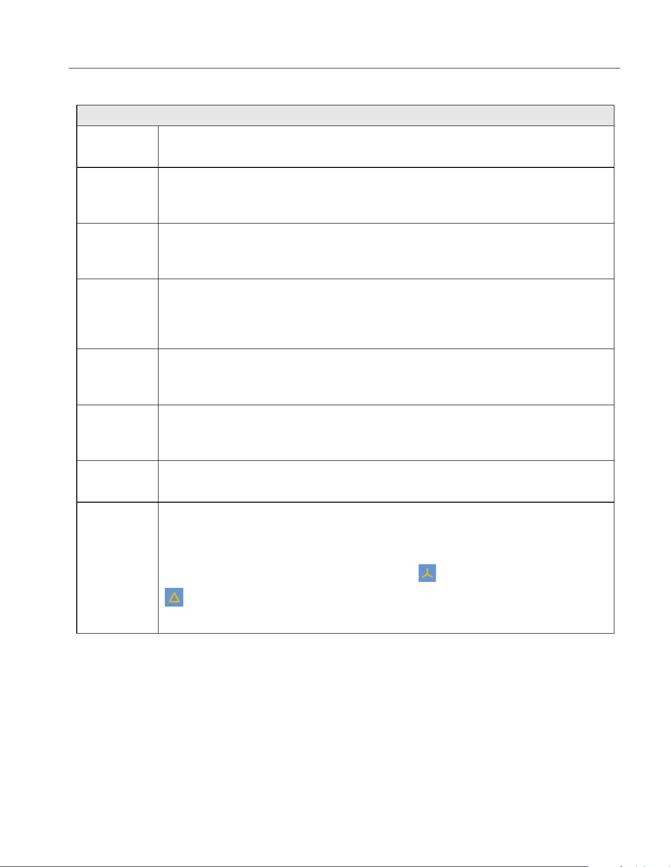
Table 18. Phasor Screen (cont.)
Phasor diagram
D
Current unbalance
The 3-phase current unbalance of the currently selected wiring group.
E
Phase information
The relative phase angle between the voltage and current of each phasor in the
currently selected wiring group, the unit is degrees (°).
F
Frequency
The frequency of the sync source signal in the currently selected wiring group. See
Set Sync Source and Update Rate for details.
G
Wiring Selection
The wiring selection of the selected wiring group. The current interface data shows
the corresponding wiring group, and to switch the wiring group use 2 (Wiring
Group).
H
Voltage phasor
The voltage phasor of the selected wiring group. The right side of the horizontal axis
is the reference and the phase angle of the reference signal is 0°.
I
Current phasor
The current phasor of the selected wiring group. The right side of the horizontal axis
is the reference and the phase angle of the reference signal is 0°.
J
Voltage and current scale
For ease of reading, only the outermost circle scale is marked in the phasor graph.
K
1 (Configure): Global configuration, see
Global Configuration.
2 (Wiring Group): Select a wiring group for measurement, see
Set the Wiring
Selection
.
3 (Y-Δ): Switch the circuit connection (Y/Δ). represents a star connection.
represents a triangle connection. See
Select Circuit Type.
5 (ZOOM): Zoom in/ out phasor, see
Zoom Phasor.
1.888.610.7664 sales@GlobalTestSupply.com
Fluke-Direct.com
Loading ...
Loading ...
Loading ...