
INSTALLATION GUIDE
for the
SB-F-BRONCG6/10TW1
SKU# 94718
2021 & Up Ford Bronco
• Installation requires appropriate tools and safety equipment.
Professional installation is recommended.
• If you prefer to perform your own installation, please read this
installation guide completely before beginning.
• Before cutting or drilling, check for potential obstacles behind
mounting surfaces.
• Mount this product securely to prevent damage or injury in
severe conditions.
INSTALLATION
DIFFI CULT Y:
ESTIMATED TIME:
2 HOURS
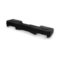
Enclosure Type: Sealed
Driver Type: 10T W1-2
Nominal Impedance: 2 ohms
Continuous Power Handling: 300 watts (RMS method)
Continued on Next Page
3
5
OUT
OF
SB-F-BRONCG6/10TW1 INSTR_SKU# 011588
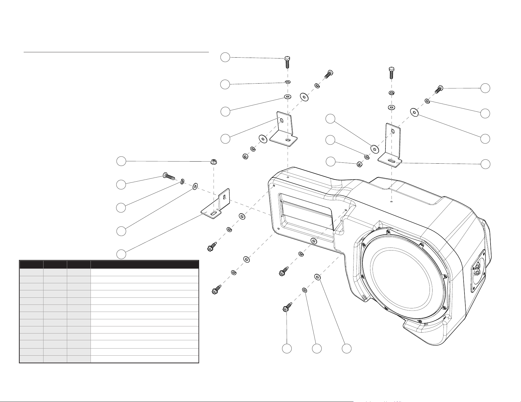
INCLUDED HARDWARE
7
1
2
3
10
6
8
1
3
2
4
2
3
2
9
1
4
2
5
Continued on Next Page
Page 2 • JL Audio, Inc., 2023
SB-F-BRONCG6/10TW1 INSTR_SKU# 011588
BOM ID Qty SKU Description
1 5 150042 1/4” - 20 x 1” Hex Head Screw
2 11 151098 1/4” Split Lock Washer
3 7 151746 1/4” Flat Washer
4 4 154580 1/4” Oversized Flat Washer 0.875” OD
5 2 151347 1/4 - 20 Hex Nut
6 1 150074 M6 - 1 mm Serrated Flange Nut
7 1 154577 Bottom Bracket
8 1 154578 Top Le Bracket
9 1 154579 Top Right Bracket
10 4 155001
1/4” x 1” Hex Head Drilling Screw
- 1 154814 Grille Assembly *
- 1 011589 Grille Drilling Template *
- 7 154581
#6 x 1/2” Phillips Round Head Screws *
* Not Shown
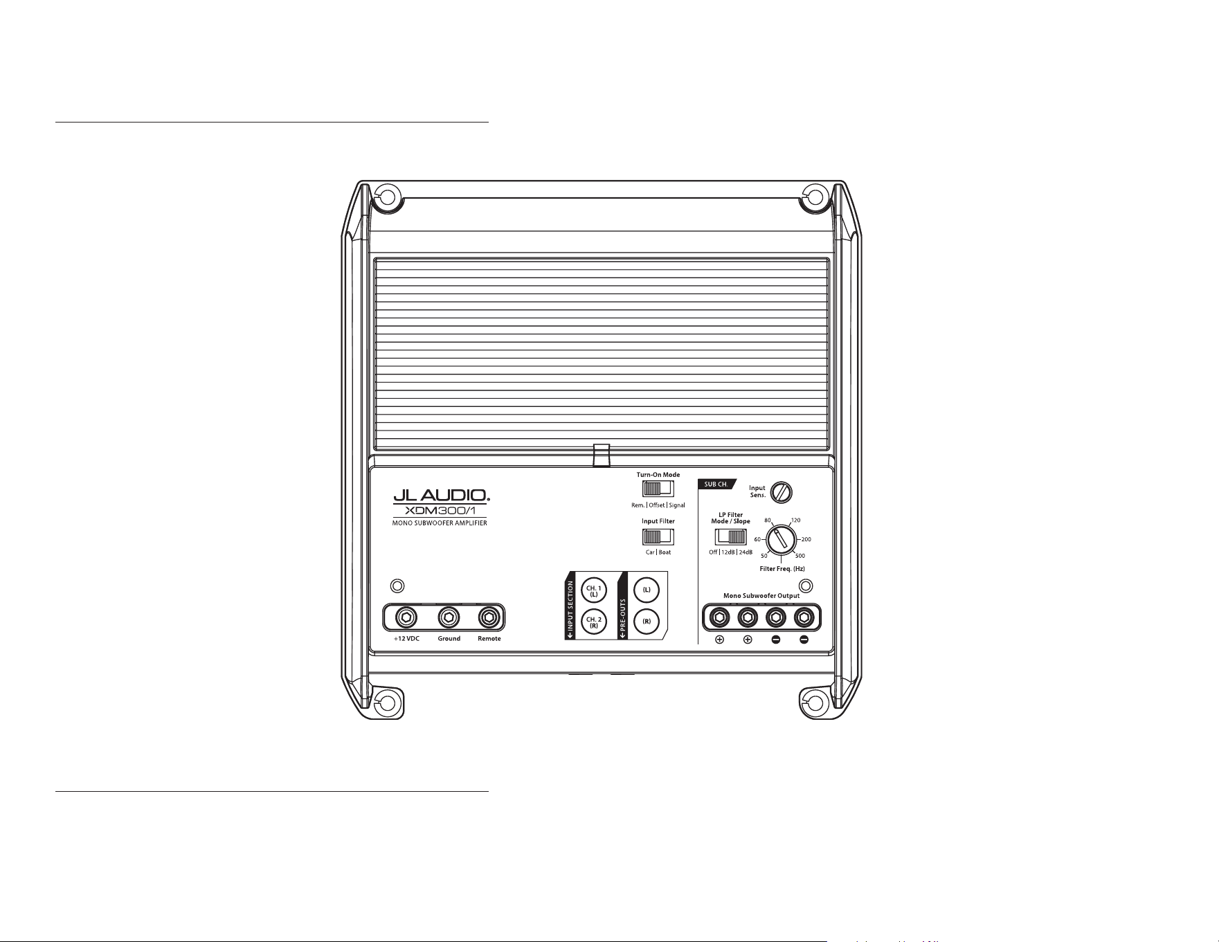
POWER RECOMMENDATION
JL Audio recommends high quality ampliers such as the JL Audio XDM300/1. The diagram below shows the recommended crossover settings for the XDM300/1. For a detailed description of the
amplier, consult the owner’s manual for the amplier. If another amplier is being used, please reference this illustration and use similar settings on that amplier.
CONNECTIONS
Using quality power, signal, and speaker wire is essential in ensuring the performance of your Stealthbox®. JL Audio recommends using a 4 AWG power kit such as the XD-PCS4-1B for your
Stealthbox® amplier. Other kits are available should you be using more than one amplier. Signal wire such as the JL Audio Premium Audio Interconnect Cables should be used to provide signal for
both channels of the amplier. JL Audio recommends using 12 AWG speaker wire for subwoofers such as our XC-BCS12-25.
Continued on Next Page
Page 3 • JL Audio, Inc., 2023
SB-F-BRONCG6/10TW1 INSTR_SKU# 011588
Page 4 • JL Audio, Inc., 2023 Continued on Next Page
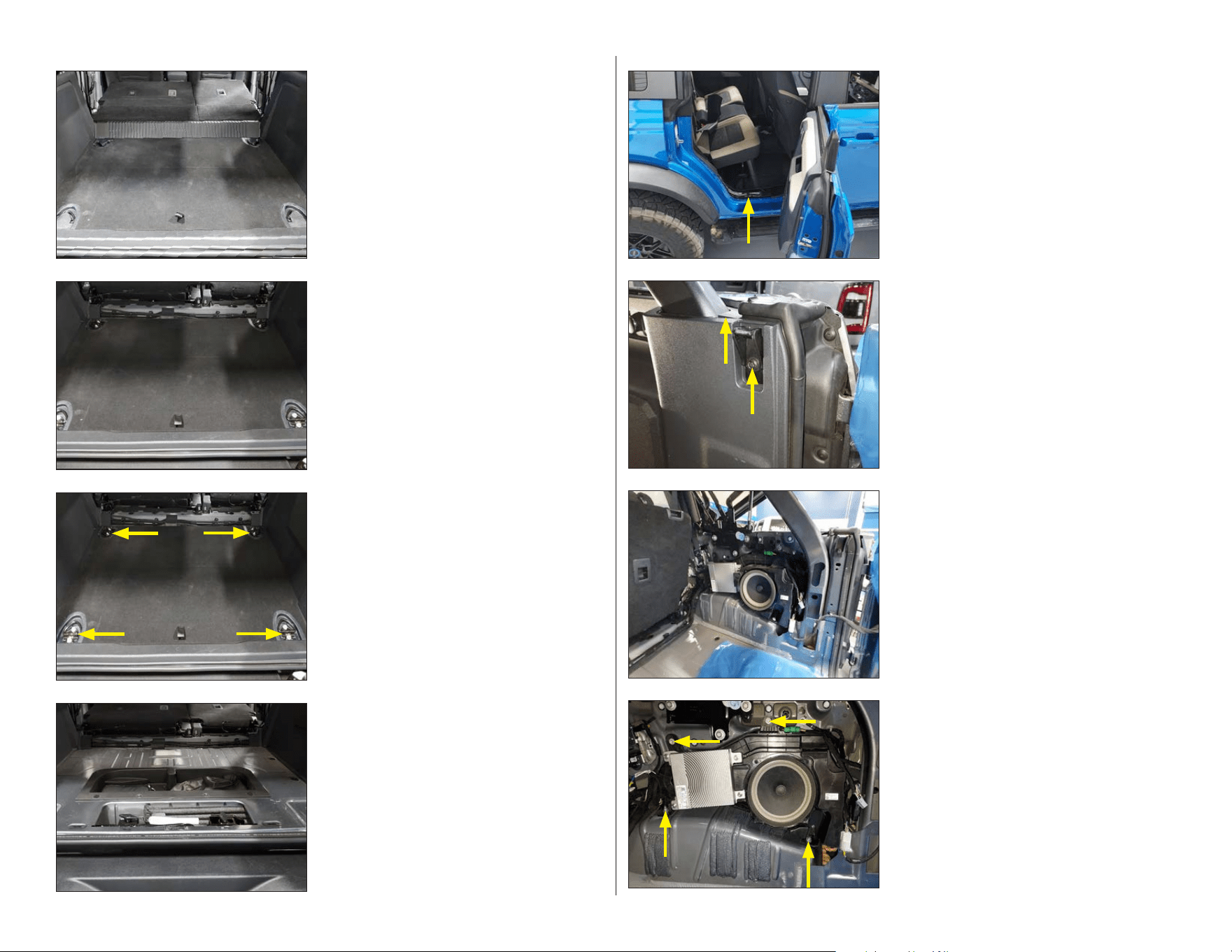
STEP 8
Remove the two indicated nuts at the bottom
and the two indicated bolts from the top of the
factory subwoofer enclosure.
Disconnect the three plugs connected to the
factory amplifier and single harness connected
to the factory subwoofer enclosure.
Remove the factory subwoofer enclosure
from the vehicle.
STEP 7
Carefully pry around the perimeter of the
factory rear panel to release it from the
mounting clips.
Disconnect the factory 12V socket, light, and
module harnesses from the backside of the
factory rear panel and remove it from vehicle.
STEP 6
This step applies to soft top Bronco
models only.
Remove the indicated factory soft top latch
sriker and pillar trim panel from the rear corner
of the passenger side panel.
STEP 5
Carefully pry and remove the passenger rear
door sill trim panel.
STEP 4
Carefully pry the rear tailgate sill trim from the
floor and remove the floor panel from
the vehicle.
STEP 3
Carefully pry and remove the four floor cargo
loop covers, then remove the exposed bolts
(two bolts per loop) from underneath.
Remove the four cargo floor loop assemblies
from the vehicle.
STEP 2
Carefully pry and remove the rear seat
bottom panel.
STEP 1
Clear the cargo area and fold the rear
seats forward.
SB-F-BRONCG6/10TW1 INSTR_SKU# 011588
Page 5 • JL Audio, Inc., 2023 Continued on Next Page
STEP 16
Align the Top Left Bracket and Top Right
Bracket with the screw assemblies passed
through the factory holes in STEP 13, allowing
the screw assemblies to pass through the top
hole in each bracket. Referring to Page 2 as a
guide, use a supplied 1/4” Split Lock Washer
and 1/4” Oversized Flat Washer 0.875” OD to
attach the brackets to the screw assemblies.
Fully tighten the Top Left Bracket and Top
Right Bracket to the enclosure and vehicle.
STEP 15
Create a screw assembly by sliding a supplied
1/4” Split Lock Washer and 1/4” Flat Washer
over a 1/4 - 20 x 1” Hex Head Screw. Using Page
2 as a guide, use the screw assembly to attach
the Bottom Bracket to the Stealthbox®
enclosure’s threaded insert and fully tighten.
Use the supplied M6 - 1 mm Serrated Flange
Nut to attach the Bottom Bracket to the factory
front bottom mounting stud and fully tighten.
STEP 14
Route the speaker cable from the amplifier and
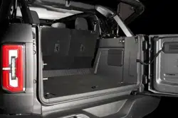
connect it to the enclosure’s terminal cup.
Carefully place the Stealthbox® into the factory
subwoofer cavity, allowing the rubber
grommet on the rear bottom of the enclosure
to rest on the factory rear bottom
mounting stud as shown.
STEP 13
Create two screw assemblies by sliding a
supplied 1/4” Split Lock Washer and
1/4” Oversized Flat Washer 0.875” OD over a
1/4 - 20 x 1” Hex Head Screw.
From behind, pass the two assemblies through
the two indicated factory holes. Use tape or
putty to temporarily hold the two assemblies
in place so they will not fall into the factory
subwoofer cavity.
STEP 12
Create two screw assemblies by sliding a
supplied 1/4” Split Lock Washer and 1/4” Flat
Washer over a 1/4 - 20 x 1” Hex Head Screw.
Using Page 2 as a guide, use the two
screw assemblies to loosely attach the Top
Left Bracket and Top Right Bracket to the
Stealthbox® enclosure’s threaded inserts.
STE P 11
Place the factory amplifier onto the
Stealthbox® as shown. Use a pick tool to mark
the four amp mounting screw holes, then pre-
drill the holes using a 1/8” drill bit. Create four
screw assemblies by sliding a supplied 1/4”
Split Lock Washer and 1/4” Flat Washer over a
1/4” x 1” Hex Head Drilling Screw. Use the four
screw assemblies to attach the factory
amplifier to the Stealthbox® enclosure. Note:
Skip this step if not using the factory amp.
STEP 10
Unmount the factory amplifier from the
factory subwoofer enclosure by removing the
four indicated bolts.
If the factory amplifier is to be retained in the
system, it will be mounted to the Stealthbox®
enclosure in STEP 11.
STEP 9
After removing the factory subwoofer
enclosure, remove the two indicated factory
screw clips.
SB-F-BRONCG6/10TW1 INSTR_SKU# 011588
Page 6 • JL Audio, Inc., 2023 Continued on Next Page
STEP 24
Use the included #6 x 1/2” Phillips Round Head
Screws to attach the Grille Assembly to the
factory panel through the holes drilled in STEP
22. Tighten the #6 x 1/2” Phillips Round Head
Screws fully. Do not overtighten the screws.
Use the supplied Grille Clamp to grasp the rear
upper edge of the factory panel as indicated.
STEP 23
Lay the included Grille Assembly face down on
a blanketed surface with the clamp clip on the
rear of the Grille Assembly at the top.
Carefully flip the factory panel over, aligning
the holes drilled in STEP 22 to the mounting
holes on the rear of the Grille Assembly.
STEP 22
Remove the Grille Drilling Template and use a
drill with a 1/8” bit to drill the screw hole
locations marked in STEP 21.
Remove the painter’s tape from the
factory panel.
STEP 21
Use a pointed pick tool or punch to mark the
mounting screw holes into the factory panel
through the perimeter of the Grille
Drilling Template as indicated.
STEP 20
Cut the top and side edges of the supplied
Grille Drilling Template as shown. Align the
edges of the Grille Drilling Template to the
lines drawn on the tape in STEP 19.
Once aligned, use tape to attach the template
to the factory panel.
STEP 19
On the top strip of tape, measure 3/8” up from
the bottom of the tape edge. Use a pencil and
a straight edge to draw a straight horizontal
line onto the tape.
On the side strip of tape, measure 5/8” out
from the inside edge of the tape. Use a pencil
and a straight edge to draw a straight vertical
line onto the tape.
STEP 18
After removing the factory grille, carefully flip
the panel over. Attach painter’s tape to the
front of the factory panel opening as shown,
aligning the edge of the tape with the top
edge and rear side edge of the grille opening.
STEP 17
Lay the factory panel face side down onto a
blanketed flat surface. Use a drill to remove the
9 plastic rivets that attach the factory
subwoofer grille to the panel.
Remove the factory subwoofer grille
from the panel.
SB-F-BRONCG6/10TW1 INSTR_SKU# 011588
+
+
+
+
+
+
+
Page 7 • JL Audio, Inc., 2023
MID/HIGH FREQUENCY DRIVER FITMENT
A variety of JL Audio coaxial and component systems will t in the factory speaker locations of your vehicle.
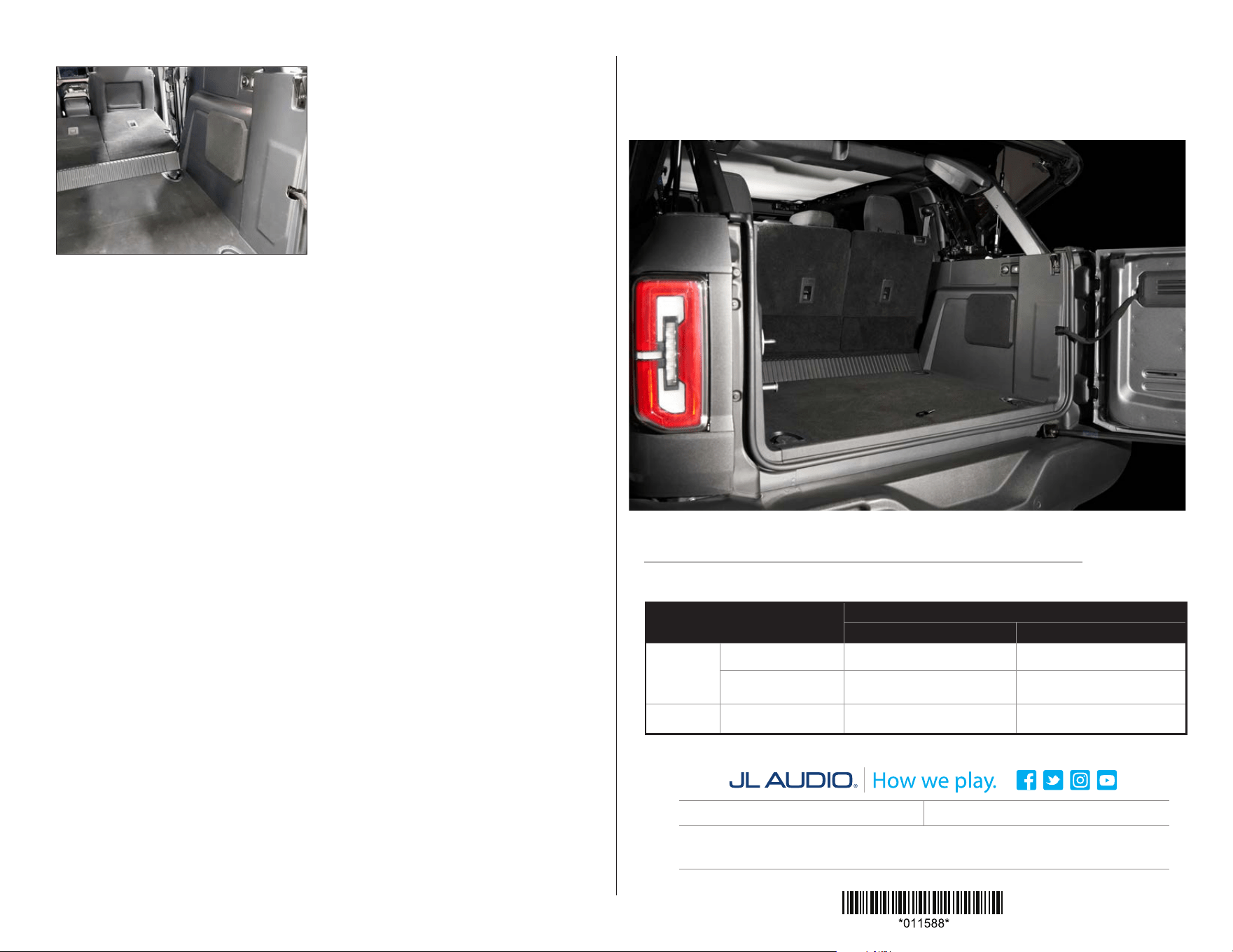
CONGRATULATIONS!
You have completed the installation for this model! Enjoy your new Stealthbox®!
SB-F-BRONCG6/10TW1 INSTR_SKU# 011588
STEP 25
Reinstall all factory panels and parts, making
sure to reconnect the factory 12V socket, light,
and module harnesses disconnected in STEP 7.
All specifications are subject to change without notice. “JL Audio®” and “How we play®” are registered trademarks of JL Audio, Inc. “Ahead of the Curve” and its respective logo are trademarks
of JL Audio, Inc.
Printed in USA • ©2023 JL Audio, Inc. • For more detailed information please visit us online at www.jlaudio.com.
(954) 443-1100
www.jlaudio.com
JLA-SKU# 011588 • ver. 6.12.23 • 10369 NORTH COMMERCE PARKWAY • MIRAMAR, FLORIDA • 33025 • USA
®
1 - Installation may require adaptor, 2 - Component woofer only
Location / OEM
Speaker Size
Suggested JL Audio Speaker Models
Coaxial Models Component Models
Front
Dash / 4-inch C1-400x, C2-400x C7-350cm
(1)
Kick Panel / 6.5-inch C1-650x, C2-650x
C1-650, C2-650, C3-650,
C7-650cw
(2)
Rear Pillar 4-inch C1-400x, C2-400x
C7-350cm
(1)