Loading ...
Loading ...
Loading ...
Part 5. Trouble Shooting
- 71 -
Copyright ©2017 LG Electronics. Inc. All right reserved.
Only for training and service purposes
LGE Internal Use Only
27
AC Input Instant over
Current Error
Inverter PCB input
current is over100A(peak)
for 2us
1. Overload operation (Pipe clogging/Covering/EEV
defect/Ref. overcharge)
2. Compressor damage (Insulation damage/Motor
damage)
3. Input voltage abnormal (L1,L2)
4. Power line assemble condition abnormal
5. Inverter PCB assembly Damage (input current
sensing part)
Display
code
Title Cause of error Check point & Normal condition
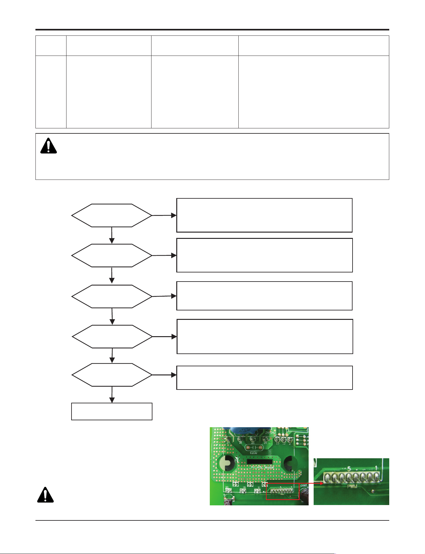
h PFCM Moudle checking method
① Set the multi tester to diode mode.
② Check short between input signal pin which are
placed below PFC Module.
③ Replace PCB assembly if it is short between pins
except No.4,5 pins.
CAUTION
PFCM module No.4,5 pins are internal short state.
No
1.Check Pipe clogging/distortion
2.Check Covering (Indoor/Outdoor Unit)
3.Check EEV connector assemble condition/normal operation
4.Check refrigerant pressure
→ Reassemble or manage if abnormality found
Is installation
condition normal?
Is compressor
Wire connection
condition normal?
1.Check inverter PCB assembly U,V,W connector connection condition
2.Check wire disconnection and wiring
3.Check compressor terminal connection condition(bad contact)
→ Reassemble if abnormality found
Is AC input Wire connection
condition normal?
1.Check L1,L2 connection condition
2.Check wire disconnection and wiring
→ Reassemble if abnormality found
Is inverter PCB assembly
normal?
Yes
No
Recheck power and
installation condition
Yes
Yes
Yes
No
No
Yes
No
Check
L~N phase voltage is 230V ± 15%
→ Check connection condition and wiring if power is abnormal
Is input voltage normal?
Check inverter PCB assembly PFCM normality
→ Replace inverter PCB assembly
WARNING
Before checking PCB or each outdoor electric parts, wait for 3 minutes after the power is off. When measuring at standby state
of power supply, after checking the measurement mode of the meter, be careful of the short-circuits with other parts.
n Error Diagnosis and Countermeasure Flow Chart
<Short Check Point>
Loading ...
Loading ...
Loading ...