
Network Video Recorder
User Manual

Legal Informaon
©2023 Hangzhou Hikvision Digital Technology Co., Ltd. All rights reserved.
About this Manual
The Manual includes instrucons for using and managing the Product. Pictures, charts, images and
all other informaon hereinaer are for descripon and explanaon only. The informaon
contained in the Manual is subject to change, without noce, due to rmware updates or other
reasons. Please nd the latest version of this Manual at the Hikvision website ( hps://
www.hikvision.com/ ).
Please use this Manual with the guidance and assistance of professionals trained in supporng the
Product.
Trademarks
and other Hikvision's trademarks and logos are the properes of
Hikvision in various jurisdicons.
Other trademarks and logos menoned are the properes of their respecve owners.
: The terms HDMI and HDMI High-Denion Mulmedia Interface, and the HDMI
Logo are trademarks or registered trademarks of HDMI Licensing Administrator, Inc. in the United
States and other countries.
Disclaimer
TO THE MAXIMUM EXTENT PERMITTED BY APPLICABLE LAW, THIS MANUAL AND THE PRODUCT
DESCRIBED, WITH ITS HARDWARE, SOFTWARE AND FIRMWARE, ARE PROVIDED "AS IS" AND "WITH
ALL FAULTS AND ERRORS". HIKVISION MAKES NO WARRANTIES, EXPRESS OR IMPLIED, INCLUDING
WITHOUT LIMITATION, MERCHANTABILITY, SATISFACTORY QUALITY, OR FITNESS FOR A PARTICULAR
PURPOSE. THE USE OF THE PRODUCT BY YOU IS AT YOUR OWN RISK. IN NO EVENT WILL HIKVISION
BE LIABLE TO YOU FOR ANY SPECIAL, CONSEQUENTIAL, INCIDENTAL, OR INDIRECT DAMAGES,
INCLUDING, AMONG OTHERS, DAMAGES FOR LOSS OF BUSINESS PROFITS, BUSINESS
INTERRUPTION, OR LOSS OF DATA, CORRUPTION OF SYSTEMS, OR LOSS OF DOCUMENTATION,
WHETHER BASED ON BREACH OF CONTRACT, TORT (INCLUDING NEGLIGENCE), PRODUCT LIABILITY,
OR OTHERWISE, IN CONNECTION WITH THE USE OF THE PRODUCT, EVEN IF HIKVISION HAS BEEN
ADVISED OF THE POSSIBILITY OF SUCH DAMAGES OR LOSS.
YOU ACKNOWLEDGE THAT THE NATURE OF THE INTERNET PROVIDES FOR INHERENT SECURITY
RISKS, AND HIKVISION SHALL NOT TAKE ANY RESPONSIBILITIES FOR ABNORMAL OPERATION,
PRIVACY LEAKAGE OR OTHER DAMAGES RESULTING FROM CYBER-ATTACK, HACKER ATTACK, VIRUS
INFECTION, OR OTHER INTERNET SECURITY RISKS; HOWEVER, HIKVISION WILL PROVIDE TIMELY
TECHNICAL SUPPORT IF REQUIRED.
YOU AGREE TO USE THIS PRODUCT IN COMPLIANCE WITH ALL APPLICABLE LAWS, AND YOU ARE
SOLELY RESPONSIBLE FOR ENSURING THAT YOUR USE CONFORMS TO THE APPLICABLE LAW.
ESPECIALLY, YOU ARE RESPONSIBLE, FOR USING THIS PRODUCT IN A MANNER THAT DOES NOT
Network Video Recorder User Manual
i

INFRINGE ON THE RIGHTS OF THIRD PARTIES, INCLUDING WITHOUT LIMITATION, RIGHTS OF
PUBLICITY, INTELLECTUAL PROPERTY RIGHTS, OR DATA PROTECTION AND OTHER PRIVACY RIGHTS.
YOU SHALL NOT USE THIS PRODUCT FOR ANY PROHIBITED END-USES, INCLUDING THE
DEVELOPMENT OR PRODUCTION OF WEAPONS OF MASS DESTRUCTION, THE DEVELOPMENT OR
PRODUCTION OF CHEMICAL OR BIOLOGICAL WEAPONS, ANY ACTIVITIES IN THE CONTEXT RELATED
TO ANY NUCLEAR EXPLOSIVE OR UNSAFE NUCLEAR FUEL-CYCLE, OR IN SUPPORT OF HUMAN
RIGHTS ABUSES.
IN THE EVENT OF ANY CONFLICTS BETWEEN THIS MANUAL AND THE APPLICABLE LAW, THE LATTER
PREVAILS.
Network Video Recorder User Manual
ii

Regulatory Informaon
FCC Informaon
Please take aenon that changes or modicaon not expressly approved by the party responsible
for compliance could void the user's authority to operate the equipment.
FCC compliance: This equipment has been tested and found to comply with the limits for a Class A
digital device, pursuant to part 15 of the FCC Rules. These limits are designed to provide
reasonable protecon against harmful interference in a residenal installaon. This equipment
generates, uses and can radiate radio frequency energy and, if not installed and used in accordance
with the instrucons, may cause harmful interference to radio communicaons. However, there is
no guarantee that interference will not occur in a parcular installaon. If this equipment does
cause harmful interference to radio or television recepon, which can be determined by turning
the equipment o and on, the user is encouraged to try to correct the interference by one or more
of the following measures:
●
Reorient or relocate the receiving antenna.
●
Increase the separaon between the equipment and receiver.
●
Connect the equipment into an outlet on a circuit dierent from that to which the receiver is
connected.
●
Consult the dealer or an experienced radio/TV technician for help.
FCC Condions
This device complies with part 15 of the FCC Rules. Operaon is subject to the following two
condions:
●
This device may not cause harmful interference.
●
This device must accept any interference received, including interference that may cause
undesired operaon.
EU Conformity Statement
This product and - if applicable - the supplied accessories too are marked
with "CE" and comply therefore with the applicable harmonized European
standards listed under the EMC Direcve 2014/30/EU, LVD Direcve 2014/
35/EU, the RoHS Direcve 2011/65/EU.
2012/19/EU (WEEE direcve): Products marked with this symbol cannot be
disposed of as unsorted municipal waste in the European Union. For
proper recycling, return this product to your local supplier upon the
Network Video Recorder User Manual
iii

purchase of equivalent new equipment, or dispose of it at designated
collecon points. For more informaon see: hp://www.recyclethis.info .
2006/66/EC (baery direcve): This product contains a baery that cannot
be disposed of as unsorted municipal waste in the European Union. See
the product documentaon for specic baery informaon. The baery is
marked with this symbol, which may include leering to indicate cadmium
(Cd), lead (Pb), or mercury (Hg). For proper recycling, return the baery to
your supplier or to a designated collecon point. For more informaon
see: hp://www.recyclethis.info .
Industry Canada ICES-003 Compliance
This device meets the CAN ICES-3 (A)/NMB-3(A) standards requirements.
Network Video Recorder User Manual
iv

Applicable Model
This manual is applicable to the following models.
Table 1-1 Applicable Model
Series Model
iDS-6700NXI-I/FA iDS-6708NXI-I/FA
iDS-6700NXI-I/S iDS-6716NXI-I/S
iDS-7600NXI-I2/X iDS-7608NXI-I2/X
iDS-7616NXI-I2/X
iDS-7600NXI-I2/P/X iDS-7608NXI-I2/8P/X
iDS-7616NXI-I2/16P/X
iDS-7700NXI-I4/X iDS-7716NXI-I4/X
iDS-7732NXI-I4/X
iDS-7700NXI-I4/16P/X iDS-7716NXI-I4/16P/X
iDS-7732NXI-I4/16P/X
iDS-7700NXI-I4/S iDS-7716NXI-I4/S
iDS-7732NXI-I4/S
iDS-7700NXI-I4/16P/S iDS-7716NXI-I4/16P/S
iDS-7732NXI-I4/16P/S
iDS-9600NXI-I8/X iDS-9616NXI-I8/X
iDS-9600NXI-I8/X iDS-9632NXI-I8/X
iDS-9664NXI-I8/X
iDS-9600NXI-I8/S iDS-9616NXI-I8/S
iDS-9632NXI-I8/S
iDS-9664NXI-I8/S
iDS-9600NXI-I16/X iDS-9616NXI-I16/X
iDS-9632NXI-I16/X
iDS-9664NXI-I16/X
iDS-96000NXI-I16 iDS-96064NXI-I16
Network Video Recorder User Manual
v

Series Model
iDS-96128NXI-I16
iDS-96000NXI-I24 iDS-96128NXI-I24
iDS-96256NXI-I24
iDS-6700NXI-I/8F(B) iDS-6708NXI-I/8F(B)
iDS-6716NXI-I/16S(B) iDS-6716NXI-I/16S(B)
iDS-7700NXI-I4/16P/16S(B) iDS-7716NXI-I4/16P/16S(B)
iDS-7732NXI-I4/16P/16S(B)
iDS-7700NXI-I4/16P/X(B) iDS-7716NXI-I4/16P/X(B)
iDS-7732NXI-I4/16P/X(B)
iDS-7700NXI-I4/16S(B) iDS-7716NXI-I4/16S(B)
iDS-7732NXI-I4/16S(B)
iDS-7700NXI-I4/X(B) iDS-7716NXI-I4/X(B)
iDS-7732NXI-I4/X(B)
iDS-9600NXI-I8/4F(B) iDS-9608NXI-I8/4F(B)
iDS-9616NXI-I8/4F(B)
iDS-9632NXI-I8/4F(B)
iDS-9600NXI-I8/8F(B) iDS-9616NXI-I8/8F(B)
iDS-9632NXI-I8/8F(B)
iDS-9664NXI-I8/8F(B)
iDS-9600NXI-I8/X(B) iDS-9616NXI-I8/X(B)
iDS-9632NXI-I8/X(B)
iDS-9664NXI-I8/X(B)
iDS-9600NXI-I8/16S(B) iDS-9616NXI-I8/16S(B)
iDS-9632NXI-I8/16S(B)
iDS-9664NXI-I8/16S(B)
iDS-9600NXI-I16/8F(B) iDS-9616NXI-I16/8F(B)
iDS-9632NXI-I16/8F(B)
iDS-9664NXI-I16/8F(B)
iDS-9600NXI-I16/X(B) iDS-9616NXI-I16/X(B)
Network Video Recorder User Manual
vi

Series Model
iDS-9632NXI-I16/X(B)
iDS-9664NXI-I16/X(B)
iDS-9600NXI-I16/16S(B) iDS-9616NXI-I16/16S(B)
iDS-9632NXI-I16/16S(B)
iDS-9664NXI-I16/16S(B)
iDS-96000NXI-I16(B) iDS-96064NXI-I16(B)
iDS-96128NXI-I16(B)
iDS-96000NXI-I24(B) iDS-96128NXI-I24(B)
iDS-96256NXI-I24(B)
iDS-7600NXI-M2/X iDS-7608NXI-M2/X
iDS-7616NXI-M2/X
iDS-7632NXI-M2/X
iDS-7600NXI-M2/P/X iDS-7608NXI-M2/8P/X
iDS-7616NXI-M2/16P/X
iDS-7700NXI-M4/X iDS-7716NXI-M4/X
iDS-7732NXI-M4/X
iDS-7700NXI-M4/16P/X iDS-7716NXI-M4/16P/X
iDS-7732NXI-M4/16P/X
iDS-9600NXI-M8/X iDS-9616NXI-M8/X
iDS-9632NXI-M8/X
iDS-9664NXI-M8/X
iDS-9600NXI-M8R/X iDS-9616NXI-M8R/X
iDS-9632NXI-M8R/X
iDS-9664NXI-M8R/X
iDS-9600NXI-M16/X iDS-9632NXI-M16/X
iDS-9664NXI-M16/X
iDS-9600NXI-M16/X iDS-9632NXI-M16R/X
iDS-9664NXI-M16R/X
iDS-9600NXI-I8/S/SL iDS-9632NXI-I8/S/SL
Network Video Recorder User Manual
vii

Series Model
iDS-9664NXI-I8/S/SL
iDS-9664NXI-I16/S/SL iDS-9664NXI-I16/S/SL
Network Video Recorder User Manual
viii
Symbol Convenons
The symbols that may be found in this document are dened as follows.
Symbol Descripon
Danger
Indicates a hazardous situaon which, if not avoided, will or could
result in death or serious injury.
Cauon
Indicates a potenally hazardous situaon which, if not avoided, could
result in equipment damage, data loss, performance degradaon, or
unexpected results.
Note
Provides addional informaon to emphasize or supplement
important points of the main text.
Network Video Recorder User Manual
ix

Safety Instrucon
●
Proper conguraon of all passwords and other security sengs is the responsibility of the
installer and/or end-user.
●
In the use of the product, you must be in strict compliance with the electrical safety regulaons
of the naon and region.
●
Firmly connect the plug to the power socket. Do not connect several devices to one power
adapter. Power o the device before connecng and disconnecng accessories and peripherals.
●
Shock hazard! Disconnect all power sources before maintenance.
●
The equipment must be connected to an earthed mains socket-outlet.
●
The socket-outlet shall be installed near the equipment and shall be easily accessible.
●
indicates hazardous live and the external wiring connected to the terminals requires
installaon by an instructed person.
●
Never place the equipment in an unstable locaon. The equipment may fall, causing serious
personal injury or death.
●
Input voltage should meet the SELV (Safety Extra Low Voltage) and the LPS (Limited Power
Source) according to the IEC62368.
●
High touch current! Connect to earth before connecng to the power supply.
●
If smoke, odor or noise rise from the device, turn o the power at once and unplug the power
cable, and then please contact the service center.
●
Use the device in conjuncon with an UPS, and use factory recommended HDD if possible.
●
This product contains a coin/buon cell baery. If the baery is swallowed, it can cause severe
internal burns in just 2 hours and can lead to death.
●
This equipment is not suitable for use in locaons where children are likely to be present.
●
CAUTION: Risk of explosion if the baery is replaced by an incorrect type.
●
Improper replacement of the baery with an incorrect type may defeat a safeguard (for
example, in the case of some lithium baery types).
●
Do not dispose of the baery into re or a hot oven, or mechanically crush or cut the baery,
which may result in an explosion.
●
Do not leave the baery in an extremely high temperature surrounding environment, which may
result in an explosion or the leakage of ammable liquid or gas.
●
Do not subject the baery to extremely low air pressure, which may result in an explosion or the
leakage of ammable liquid or gas.
●
Dispose of used baeries according to the instrucons.
●
Keep body parts away from fan blades and motors. Disconnect the power source during
servicing.
●
Keep body parts away from motors. Disconnect the power source during servicing.
●
Use only power supplies same with the original model, or LPS power supplies with the same
voltage and electric current.
Network Video Recorder User Manual
x

Prevenve and Cauonary Tips
Before connecng and operang your device, please be advised of the following ps:
●
The device is designed for indoor use only. Install it in a well-venlated, dust-free environment
without liquids.
●
Ensure recorder is properly secured to a rack or shelf. Major shocks or jolts to the recorder as a
result of dropping it may cause damage to the sensive electronics within the recorder.
●
The equipment shall not be exposed to dripping or splashing and that no objects lled with
liquids shall be placed on the equipment, such as vases.
●
No naked ame sources, such as lighted candles, should be placed on the equipment.
●
The venlaon should not be impeded by covering the venlaon openings with items, such as
newspapers, table-cloths, curtains, etc. The openings shall never be blocked by placing the
equipment on a bed, sofa, rug or other similar surface.
●
For certain models, ensure correct wiring of the terminals for connecon to an AC mains supply.
●
For certain models, the equipment has been designed, when required, modied for connecon
to an IT power distribuon system.
●
idenes the baery holder itself and idenes the posioning of the cell(s) inside the
baery holder.
●
+ idenes the posive terminal(s) of equipment which is used with, or generates direct current.
+ idenes the negave terminal(s) of equipment which is used with, or generates direct
current.
●
Keep a minimum 200 mm (7.87 inch) distance around the equipment for sucient venlaon.
●
For certain models, ensure correct wiring of the terminals for connecon to an AC mains supply.
●
Use only power supplies listed in the user manual or user instrucon.
●
The USB port of the equipment is used for connecng to a mouse, keyboard, USB ash drive, or
Wi-Fi dongle only.
●
Use only power supplies listed in the user manual or user instrucon.
●
Do not touch the sharp edges or corners.
●
When the device is running above 45 °C (113 °F), or its HDD temperature in S.M.A.R.T. exceeds
the stated value, please ensure the device is running in a cool environment, or replace HDD(s) to
make the HDD temperature in S.M.A.R.T. below the stated value.
Network Video Recorder User Manual
xi

Contents
Chapter 1 Basic Operaon .......................................................................................................... 1
1.1 Acvate Your Device .............................................................................................................. 1
1.1.1 Default User and IP Address ......................................................................................... 1
1.1.2 Acvate via Local Menu ................................................................................................ 1
1.1.3 Acvate via SADP .......................................................................................................... 2
1.1.4 Acvate via Client Soware .......................................................................................... 3
1.1.5 Acvate via Web Browser ............................................................................................. 6
1.2 Congure TCP/IP .................................................................................................................... 6
1.3 Congure HDD ....................................................................................................................... 7
1.4 Add Network Camera ............................................................................................................. 8
1.4.1 Add Automacally Searched Online Network Camera ................................................. 8
1.4.2 Add Network Camera Manually .................................................................................... 9
1.4.3 Add Network Camera Through PoE ............................................................................ 10
1.4.4 Add Network Camera via Customized Protocol .......................................................... 12
1.5 Connect to Plaorm ............................................................................................................. 13
1.5.1 Congure ISUP ............................................................................................................ 13
1.5.2 Congure Hik-Connect ................................................................................................ 15
Chapter 2 Camera Sengs ........................................................................................................ 17
2.1 View Camera Error Informaon ........................................................................................... 17
2.2 Congure Image Parameters ................................................................................................ 17
2.3 Congure OSD ...................................................................................................................... 17
2.4 Congure Privacy Mask ........................................................................................................ 18
2.5 IP Camera Time Sync ............................................................................................................ 19
2.6 Import Network Camera Cercate ..................................................................................... 20
2.7 Import/Export IP Camera Conguraon Files ...................................................................... 20
2.8 Save Camera VCA Data ......................................................................................................... 21
Network Video Recorder User Manual
xii

2.9 Upgrade IP Cameras ............................................................................................................. 21
Chapter 3 Live View .................................................................................................................. 23
3.1 Start Live View ..................................................................................................................... 23
3.2 Congure Live View Sengs ................................................................................................ 24
3.3 Congure Auto-Switch of Cameras ...................................................................................... 25
3.4 Congure Live View Layout .................................................................................................. 25
3.4.1 Congure Custom Live View Layout ............................................................................ 25
3.4.2 Congure Live View Mode .......................................................................................... 26
3.5 Congure Channel-Zero Encoding ....................................................................................... 27
3.6 Main and Auxiliary Ports Strategy ........................................................................................ 27
3.7 Digital Zoom ......................................................................................................................... 28
3.8 Fisheye View ........................................................................................................................ 29
3.9 3D Posioning ...................................................................................................................... 30
3.10 Live View Strategy .............................................................................................................. 30
3.11 Person Passing ................................................................................................................... 30
3.12 PTZ Control ........................................................................................................................ 33
3.12.1 Congure PTZ Parameters ......................................................................................... 33
3.12.2 Set a Preset ............................................................................................................... 33
3.12.3 Call a Preset .............................................................................................................. 34
3.12.4 Set a Patrol ................................................................................................................ 34
3.12.5 Call a Patrol ............................................................................................................... 36
3.12.6 Set a Paern .............................................................................................................. 36
3.12.7 Call a Paern ............................................................................................................. 37
3.12.8 Set Linear Scan Limit ................................................................................................. 37
3.12.9 One-Touch Park ......................................................................................................... 38
3.12.10 Auxiliary Funcons .................................................................................................. 39
Chapter 4 Recording and Playback ............................................................................................ 40
4.1 Recording ............................................................................................................................. 40
Network Video Recorder User Manual
xiii

4.1.1 Congure Recording Parameters ................................................................................ 40
4.1.2 Enable H.265 Stream Access ....................................................................................... 42
4.1.3 ANR ............................................................................................................................. 42
4.1.4 Manual Recording ....................................................................................................... 42
4.1.5 Congure Recording Schedule .................................................................................... 42
4.1.6 Congure Connuous Recording ................................................................................ 44
4.1.7 Congure Moon Detecon Triggered Recording ...................................................... 45
4.1.8 Congure Event Triggered Recording .......................................................................... 45
4.1.9 Congure Alarm Triggered Recording ......................................................................... 45
4.1.10 Congure Picture Capture ......................................................................................... 46
4.1.11 Congure Holiday Recording ..................................................................................... 46
4.1.12 Congure Redundant Recording and Capture .......................................................... 47
4.2 Playback ............................................................................................................................... 48
4.2.1 Instant Playback .......................................................................................................... 48
4.2.2 Play Normal Video ...................................................................................................... 49
4.2.3 Play Smart Searched Video ......................................................................................... 50
4.2.4 Play Custom Searched Files ......................................................................................... 50
4.2.5 Play Tag Files ............................................................................................................... 51
4.2.6 Play by Sub-periods ..................................................................................................... 52
4.2.7 Play Log Files ............................................................................................................... 52
4.2.8 Play External Files ....................................................................................................... 53
4.3 Playback Operaons ............................................................................................................ 53
4.3.1 View Playback Error Informaon ................................................................................ 53
4.3.2 Set Play Strategy in Important/Custom Mode ............................................................ 53
4.3.3 Edit Video Clips ........................................................................................................... 54
4.3.4 Switch between Main Stream and Sub-Stream .......................................................... 54
4.3.5 Switch Audio Source ................................................................................................... 54
4.3.6 Thumbnails View ......................................................................................................... 55
Network Video Recorder User Manual
xiv

4.3.7 Fisheye View ............................................................................................................... 55
4.3.8 Fast View ..................................................................................................................... 56
4.3.9 Digital Zoom ................................................................................................................ 56
4.3.10 POS Informaon Overlay ........................................................................................... 57
Chapter 5 Picture Capture ......................................................................................................... 58
5.1 Congure Parameters .......................................................................................................... 58
5.2 Congure Capture Schedule ................................................................................................ 58
5.3 Congure Holiday Capture Schedule ................................................................................... 58
Chapter 6 Event ........................................................................................................................ 60
6.1 Normal Event Alarm ............................................................................................................. 60
6.1.1 Congure Moon Detecon Alarms ........................................................................... 60
6.1.2 Congure Video Loss Alarms ....................................................................................... 60
6.1.3 Congure Video Tampering Alarms ............................................................................ 61
6.1.4 Congure Sensor Alarms ............................................................................................. 61
6.1.5 Congure Excepons Alarms ...................................................................................... 61
6.1.6 Congure Combined Alarm ......................................................................................... 62
6.2 VCA Event Alarm .................................................................................................................. 63
6.2.1 Temperature Screening ............................................................................................... 63
6.2.2 Transparent Transmission ........................................................................................... 64
6.2.3 Hard Hat Detecon ..................................................................................................... 65
6.2.4 People Gathering Detecon ........................................................................................ 65
6.2.5 Fast Moving Detecon ................................................................................................ 66
6.2.6 Parking Detecon ........................................................................................................ 67
6.2.7 Unaended Baggage Detecon .................................................................................. 68
6.2.8 Object Removal Detecon .......................................................................................... 69
6.2.9 Audio Excepon Detecon .......................................................................................... 70
6.2.10 Defocus Detecon ..................................................................................................... 71
6.2.11 Sudden Scene Change Detecon .............................................................................. 72
Network Video Recorder User Manual
xv

6.2.12 PIR Alarm .................................................................................................................. 73
6.2.13 Thermal Camera Detecon ....................................................................................... 74
6.2.14 Queue Management ................................................................................................. 75
6.3 Congure Arming Schedule ................................................................................................. 75
6.4 Congure Linkage Acons .................................................................................................... 76
6.4.1 Congure Auto-Switch Full Screen Monitoring ........................................................... 76
6.4.2 Congure Buzzer ......................................................................................................... 77
6.4.3 Nofy Surveillance Center .......................................................................................... 77
6.4.4 Congure Email Linkage .............................................................................................. 77
6.4.5 Congure Audio Alert ................................................................................................. 78
6.4.6 Trigger Alarm Output .................................................................................................. 78
6.4.7 Congure Audio and Light Alarm Linkage ................................................................... 78
6.4.8 Congure PTZ Linkage ................................................................................................. 79
Chapter 7 Smart Analysis .......................................................................................................... 80
7.1 Engine Conguraon ........................................................................................................... 80
7.2 Task Conguraon ............................................................................................................... 81
7.3 Self-Learning ........................................................................................................................ 82
7.3.1 Training Task ................................................................................................................ 82
7.3.2 Algorithm Management .............................................................................................. 83
7.4 Face Picture Comparison ..................................................................................................... 83
7.4.1 Face Grading Conguraon ......................................................................................... 83
7.4.2 Face Capture ............................................................................................................... 84
7.4.3 Face Picture Library Management .............................................................................. 85
7.4.4 Face Picture Comparison Alarm .................................................................................. 86
7.4.5 People Frequency Alarm ............................................................................................. 90
7.4.6 Face Picture Search ..................................................................................................... 93
7.5 Perimeter Protecon ........................................................................................................... 96
7.5.1 Line Crossing Detecon ............................................................................................... 96
Network Video Recorder User Manual
xvi

7.5.2 Intrusion Detecon ..................................................................................................... 98
7.5.3 Region Entrance Detecon ....................................................................................... 100
7.5.4 Region Exing Detecon ........................................................................................... 101
7.6 Human Body Detecon ...................................................................................................... 103
7.6.1 Human Body Detecon ............................................................................................. 103
7.6.2 Human Body Search .................................................................................................. 104
7.7 Mul-Target-Type Detecon .............................................................................................. 106
7.8 Vehicle Detecon ............................................................................................................... 107
7.8.1 Congure Vehicle Detecon ..................................................................................... 107
7.8.2 Vehicle Search ........................................................................................................... 108
7.9 Object Thrown from Building ............................................................................................. 108
7.10 Face Counng .................................................................................................................. 111
7.11 Target Detecon ............................................................................................................... 113
7.12 People Counng ............................................................................................................... 113
7.13 Heat Map ......................................................................................................................... 114
Chapter 8 IoT .......................................................................................................................... 116
8.1 Add an IoT Device .............................................................................................................. 116
8.1.1 Add an Access Control Device ................................................................................... 116
8.1.2 Add an Alarm Device ................................................................................................. 117
8.1.3 Add Network Audio Device ....................................................................................... 119
8.2 Congure the Linkage Acon and Arming Schedule .......................................................... 119
8.3 Congure OSD .................................................................................................................... 120
8.4 Congure Audio Parameters .............................................................................................. 121
8.5 Search the IoT Record ........................................................................................................ 122
8.6 IoT Video/Picture ............................................................................................................... 123
8.6.1 Congure the Event Recording/Capturing ................................................................ 124
8.6.2 Search IoT Video ....................................................................................................... 125
Chapter 9 File Management .................................................................................................... 127
Network Video Recorder User Manual
xvii

9.1 Search Files ........................................................................................................................ 127
9.2 Export Files ........................................................................................................................ 127
9.3 Quick Backup ..................................................................................................................... 128
9.4 Smart Search ...................................................................................................................... 128
Chapter 10 Storage ................................................................................................................. 129
10.1 Storage Device Management ........................................................................................... 129
10.1.1 SSD Management .................................................................................................... 129
10.1.2 Manage Local HDD .................................................................................................. 130
10.1.3 Add a Network Disk ................................................................................................ 132
10.1.4 Congure Cloud Storage ......................................................................................... 133
10.1.5 Manage eSATA ......................................................................................................... 134
10.1.6 Dynamically Adjust Recording Wring Buer ......................................................... 136
10.2 Disk Array ......................................................................................................................... 137
10.2.1 Create a Disk Array .................................................................................................. 137
10.2.2 Rebuild an Array ...................................................................................................... 139
Chapter 11 Hot Spare Device Backup ...................................................................................... 142
11.1 Set Working Device .......................................................................................................... 142
11.2 Set Hot Spare Device ........................................................................................................ 142
11.3 Manage Hot Spare System ............................................................................................... 143
Chapter 12 Network Sengs .................................................................................................. 145
12.1 Congure DDNS ............................................................................................................... 145
12.2 Congure PPPoE .............................................................................................................. 145
12.3 Congure Port Mapping (NAT) ......................................................................................... 146
12.4 Congure SNMP ............................................................................................................... 147
12.5 Congure Email ................................................................................................................ 149
12.6 Congure Port .................................................................................................................. 150
12.7 Congure ONVIF .............................................................................................................. 151
Chapter 13 POS Conguraon ................................................................................................. 153
Network Video Recorder User Manual
xviii

13.1 Congure POS Connecon ............................................................................................... 153
13.2 Congure POS Text Overlay ............................................................................................. 156
13.3 Congure POS Alarm ........................................................................................................ 157
Chapter 14 User Management and Security ............................................................................ 159
14.1 Manage User Accounts .................................................................................................... 159
14.1.1 Add a User ............................................................................................................... 159
14.1.2 Edit the Admin User ................................................................................................ 160
14.1.3 Edit an Operator/Guest User .................................................................................. 161
14.2 Manage User Permissions ................................................................................................ 161
14.2.1 Set User Permissions ............................................................................................... 161
14.2.2 Set Live View Permission on Lock Screen ................................................................ 164
14.2.3 Set Double Vericaon Permission for Non-admin Users ....................................... 165
14.3 Congure Password Security ........................................................................................... 165
14.3.1 Export GUID File ...................................................................................................... 165
14.3.2 Congure Security Quesons .................................................................................. 166
14.3.3 Congure Reserved Email ....................................................................................... 167
14.4 Reset Password ................................................................................................................ 168
14.4.1 Reset Password by GUID ......................................................................................... 168
14.4.2 Reset Password by Security Quesons ................................................................... 169
14.4.3 Reset Password by Reserved Email ......................................................................... 169
14.4.4 Reset Password by Hik-Connect .............................................................................. 170
Chapter 15 System Management ............................................................................................ 171
15.1 Congure Device .............................................................................................................. 171
15.2 Congure Time ................................................................................................................. 171
15.2.1 Manual Time Synchronizaon ................................................................................. 171
15.2.2 NTP Synchronizaon ............................................................................................... 172
15.2.3 DST Synchronizaon ............................................................................................... 172
15.3 Audio Management ......................................................................................................... 173
Network Video Recorder User Manual
xix

15.4 Congure Enhanced SVC Mode ....................................................................................... 173
15.5 Network Detecon ........................................................................................................... 173
15.5.1 Network Trac Monitoring ..................................................................................... 173
15.5.2 Test Network Delay and Packet Loss ....................................................................... 174
15.5.3 Export Network Packet ........................................................................................... 175
15.5.4 Network Resource Stascs .................................................................................... 175
15.6 Storage Device Maintenance ........................................................................................... 176
15.6.1 Bad Sector Detecon .............................................................................................. 176
15.6.2 S.M.A.R.T. Detecon ................................................................................................ 176
15.6.3 HDD Health Detecon ............................................................................................. 177
15.6.4 Congure Disk Clone ............................................................................................... 178
15.6.5 Repair Database ...................................................................................................... 179
15.7 Upgrade Device ................................................................................................................ 179
15.7.1 Upgrade by Local Backup Device ............................................................................ 179
15.7.2 Upgrade by FTP ....................................................................................................... 180
15.7.3 Upgrade by Web Browser ....................................................................................... 180
15.7.4 Upgrade by Hik-Connect ......................................................................................... 181
15.8 Import/Export Device Conguraon Files ........................................................................ 181
15.9 Log Management ............................................................................................................. 182
15.9.1 Log Storage ............................................................................................................. 182
15.9.2 Search & Export Log Files ........................................................................................ 182
15.9.3 Upload Logs to the Server ....................................................................................... 183
15.9.4 One-Way Authencaon ........................................................................................ 184
15.9.5 Two-Way Authencaon ........................................................................................ 185
15.10 Export Diagnosc Informaon ....................................................................................... 186
15.11 Restore Default Sengs ................................................................................................. 186
15.12 Schedule Reboot ............................................................................................................ 187
15.13 Security Management .................................................................................................... 187
Network Video Recorder User Manual
xx

15.13.1 Congure ONVIF ................................................................................................... 187
15.13.2 IP/MAC Address Filter ........................................................................................... 187
15.13.3 RTSP Authencaon ............................................................................................. 188
15.13.4 ISAPI Service .......................................................................................................... 189
15.13.5 HTTP Authencaon ............................................................................................. 189
15.13.6 IP Camera Occupaon Detecon .......................................................................... 189
Chapter 16 Appendix .............................................................................................................. 190
16.1 Glossary ........................................................................................................................... 190
16.2 Communicaon Matrix .................................................................................................... 191
16.3 Device Command ............................................................................................................. 191
16.4 Frequently Asked Quesons ............................................................................................ 192
16.4.1 Why is there a part of channels displaying “No Resource” or turning black screen in
mul-screen live view? ...................................................................................................... 192
16.4.2 Why is the video recorder nofying the stream type is not supported? ................ 192
16.4.3 Why is the video recorder nofying risky password aer a network camera is added?
............................................................................................................................................ 193
16.4.4 How to improve the playback image quality? ......................................................... 193
16.4.5 How to conrm the video recorder is using H.265 to record video? ...................... 193
16.4.6 Why is the meline at playback not constant? ....................................................... 193
16.4.7 Why is the video recorder nofying the network is unreachable when a network
camera is being added? ..................................................................................................... 194
16.4.8 Why is the IP address of network camera being changed automacally? .............. 194
16.4.9 Why is the video recorder nofying IP conict? ..................................................... 194
16.4.10 Why is image geng stuck when playing back by single or mul-channel cameras?
............................................................................................................................................ 195
16.4.11 Why does my video recorder make a beeping sound aer boong? ................... 195
16.4.12 Why is there no recorded video aer the moon detecon is set? ..................... 195
16.4.13 Why is the video sound quality not good? ............................................................ 196
Network Video Recorder User Manual
xxi
Chapter 1 Basic Operaon
1.1 Acvate Your Device
1.1.1 Default User and IP Address
●
Default administrator account: admin.
●
Default IPv4 address: 192.168.1.64.
1.1.2 Acvate via Local Menu
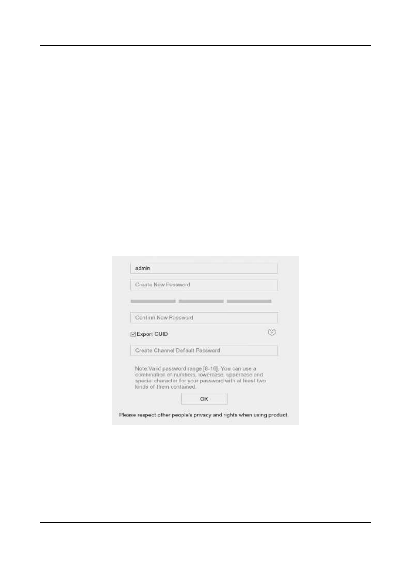
For the rst-me access, you have to set an admin password to acvate your device. No operaon
is allowed before acvaon. You can also acvate the device via web browser, SADP or client
soware.
Steps
1. Enter the admin password twice.
Figure 1-1 Acvate via Local Menu
Network Video Recorder User Manual
1

Warning
We highly recommend you to create a strong password of your own choosing (using a minimum
of 8 characters, including at least three kinds of following categories: upper case leers, lower
case leers, numbers, and special characters) in order to increase the security of your product.
And we recommend you change your password regularly, especially in the high security system,
changing the password monthly or weekly can beer protect your product.
2. Enter a password to acvate network cameras that are connected to the device.
3. Click OK.
Note
Aer the device is acvated, you should properly keep the password.
What to do next
Follow the wizard to set basic parameters.
●
There are methods to reset your password when you forget. You have to congure at least one
password reseng method aer acvaon.
●
For Hik-Connect conguraon, refer to Congure Hik-Connect for details.
1.1.3 Acvate via SADP
SADP soware is used for detecng the online device, acvang the device, and reseng its
password.
Before You Start
Get the SADP soware from the supplied disk or the ocial website, and install the SADP
according to the prompts.
Steps
1. Connect your video recorder power supply to an electrical outlet and turn on it.
2. Run the SADP soware to search the online recorders.
3. Check the recorder status from the device list, and select the inacve recorder.
Network Video Recorder User Manual
2
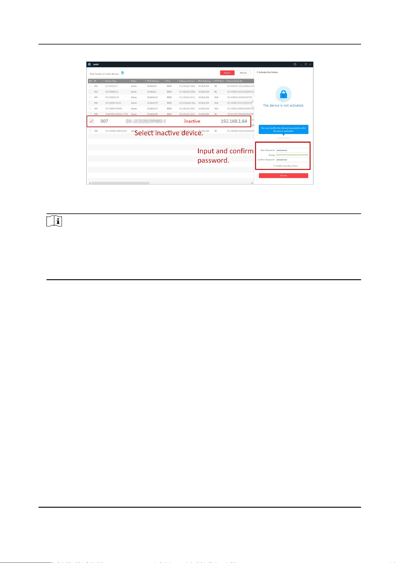
Figure 1-2 Acvate via SADP
4. Create and input the new password in the password eld, and conrm the password.
Note
We highly recommend you to create a strong password of your own choosing (using a minimum
of 8 characters, including at least three kinds of following categories: upper case leers, lower
case leers, numbers, and special characters) in order to increase the security of your product.
And we recommend you change your password regularly, especially in the high security system,
changing the password monthly or weekly can beer protect your product.
5. Click Acvate.
1.1.4 Acvate via Client Soware
The client soware is versale video management soware for mulple kinds of devices.
Before You Start
Get the client soware from the supplied disk or the ocial website, and install the soware
according to the prompts.
Steps
1. Run the client soware and the control panel of the soware pops up, as shown below.
Network Video Recorder User Manual
3
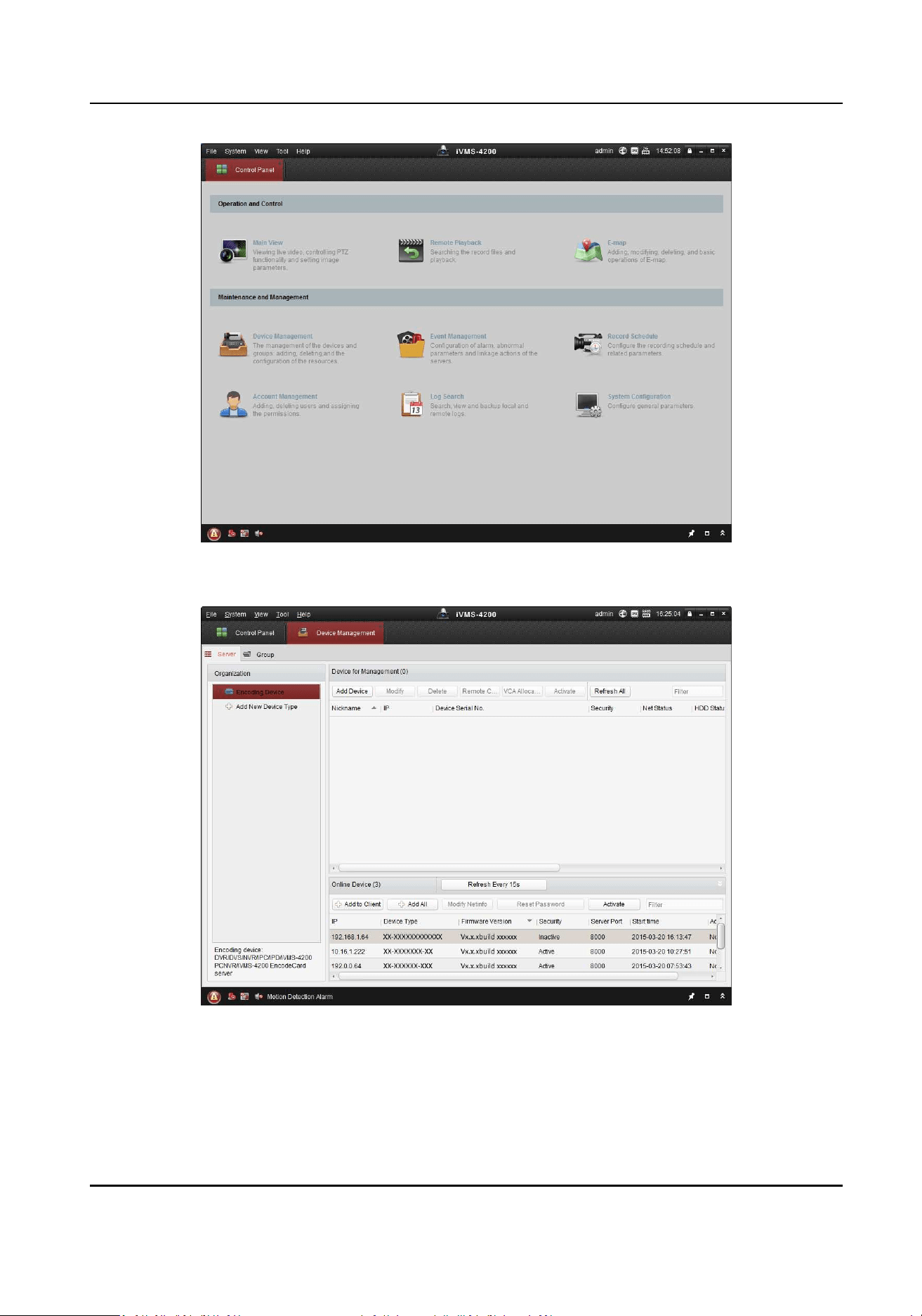
Figure 1-3 Control Panel
2. Click Device Management to enter the Device Management interface, as shown below.
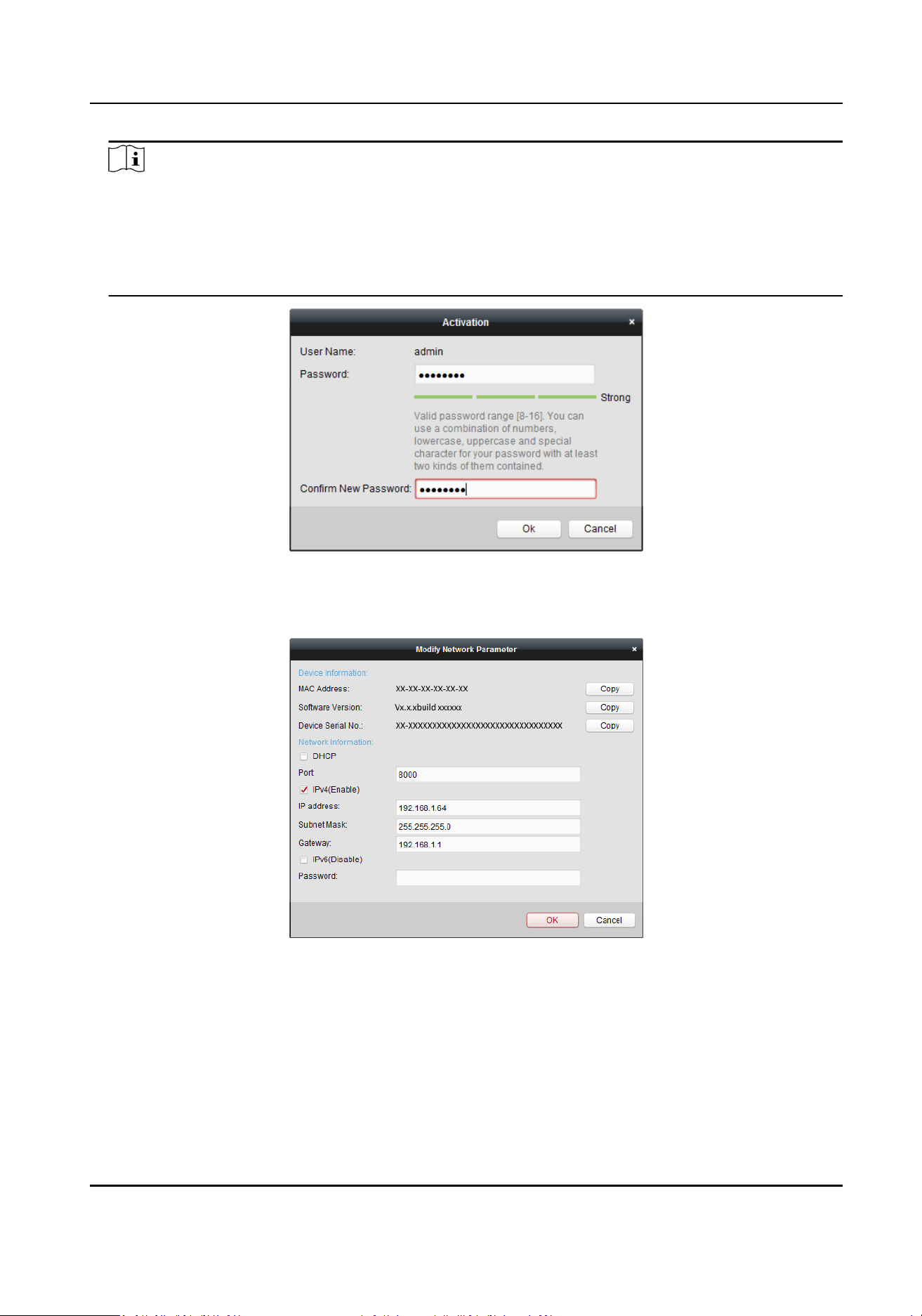
Figure 1-4 Device Management Interface
3. Check the recorder status from the device list, and select an inacve recorder.
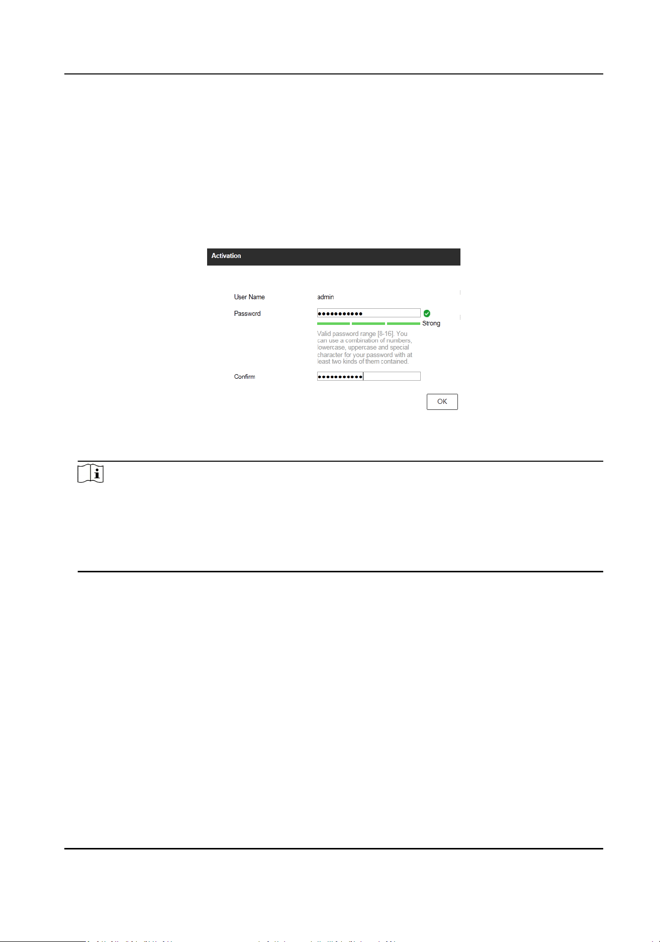
4. Click Acvate to pop up the Acvaon interface.
5. Create a password and input the password in the password eld, and conrm the password.
Network Video Recorder User Manual
4
Note
We highly recommend you to create a strong password of your own choosing (using a minimum
of 8 characters, including at least three kinds of following categories: upper case leers, lower
case leers, numbers, and special characters) in order to increase the security of your product.
And we recommend you change your password regularly, especially in the high security system,
changing the password monthly or weekly can beer protect your product.
Figure 1-5 Acvaon
6. Click OK to start acvaon.
7. Click Modify Nenfo to pop up the Network Parameter Modicaon interface, as shown below.
Figure 1-6 Modify Network Parameters
8. Change the recorder IP address to the same subnet with your computer.
-
Modify the IP address manually.
-
Check Enable DHCP.
9. Input the password to acvate your IP address modicaon.
Network Video Recorder User Manual
5
1.1.5 Acvate via Web Browser
You can get access to the recorder via web browser. You may use one of the following web
browsers: Internet Explorer 6.0 and above, Apple Safari, Mozilla Firefox, and Google Chrome. The
supported resoluons include 1024 × 768 and above.
Steps
1. Enter the IP address in web browser, and then press Enter. The default IP address is
192.168.1.64.
Figure 1-7 Web Browser Acvaon
2. Set the password for the admin user account.
Note
We highly recommend you to create a strong password of your own choosing (using a minimum
of 8 characters, including at least three kinds of following categories: upper case leers, lower
case leers, numbers, and special characters) in order to increase the security of your product.
And we recommend you change your password regularly, especially in the high security system,
changing the password monthly or weekly can beer protect your product.
3. Click OK.
1.2 Congure TCP/IP
TCP/IP must be properly congured before operang your device over a network. Both IPv4 and
IPv6 are available.
Steps
1. Go to System → Network → TCP/IP .
Network Video Recorder User Manual
6
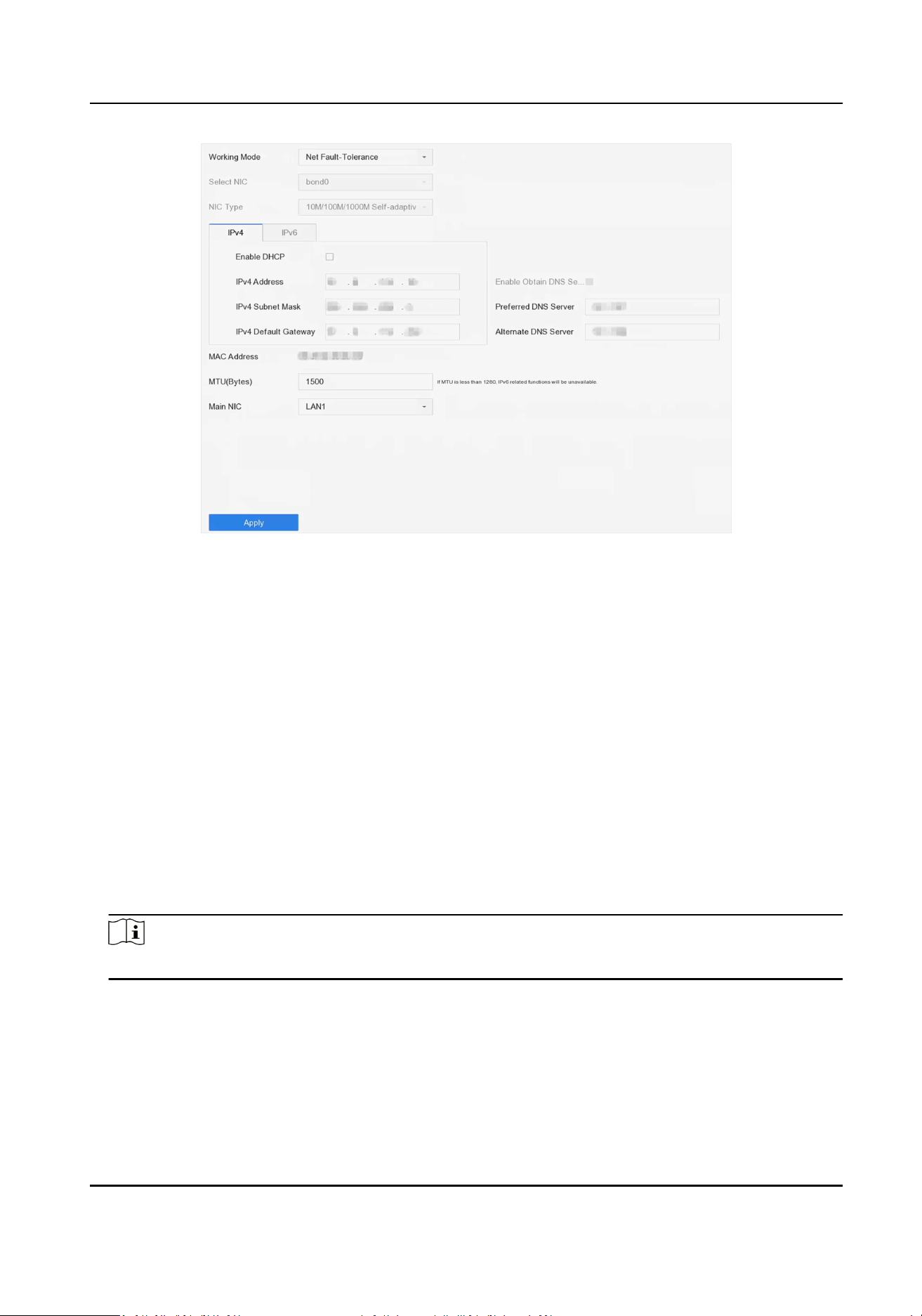
Figure 1-8 TCP/IP Sengs
2. Select Working Mode as Net-Fault Tolerance or Mul-Address Mode.
Net-Fault Tolerance
The two NIC cards use the same IP address, and you can select the main NIC to LAN1 or LAN2.
In this way, in case of one NIC card failure, the device will automacally enable another
standby NIC card so as to ensure the normal running of the system.
Mul-Address Mode
The parameters of the two NIC cards can be congured independently. You can select LAN1
or LAN2 under Select NIC for parameter sengs. Select one NIC card as the default route.
When the system connects with the extranet, the data will be forwarded through the default
route.
3. Click IPv4 or IPv6 as you required.
4. Oponal: Check Enable DHCP to obtain IP sengs automacally if a DHCP server is available on
the network.
5. Set related parameters.
Note
Valid MTU value range is from 500 to 1500.
6. Click Apply.
1.3 Congure HDD
Ensure the video recorder storage media is well. You can install at least one HDD and inialize it, or
create a RAID and inialize it.
Network Video Recorder User Manual
7
1.4 Add Network Camera
Before you can get live video or record the video les, you must add the network cameras to the
connecon list of the device.
Before You Start
Ensure the network connecon is valid and correct and the IP camera to add has been acvated.
Steps
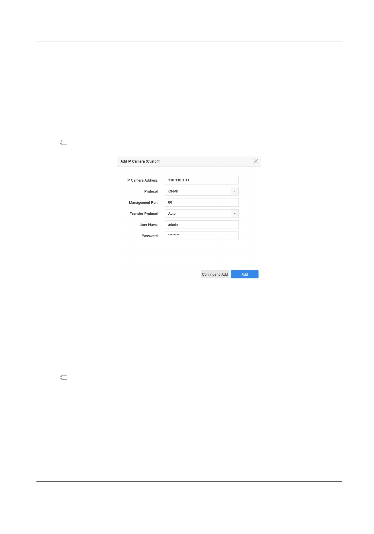
1. Click on the main menu bar.
2. Click Custom Add tab on the tle bar.
Figure 1-9 Add IP Camera
3. Enter IP address, protocol, management port, and other IP camera informaon to add.
4. Enter the login user name and password of the IP camera.
5. Click Add to nish the adding of the IP camera.
6. Oponal: Click Connue to Add to connue to add addional IP cameras.
1.4.1 Add Automacally Searched Online Network Camera
Steps
1. Click
on the main menu.
2. Click Number of Unadded Online Device at the boom.
3. Select the automacally searched online network cameras.
4. Click Add to add the camera which has the same login password with the video recorder.
Network Video Recorder User Manual
8
Figure 1-10 Add Automacally Searched Online Network Camera
Note
If the network camera to add has not been acvated, you can acvate it in the network camera
list of camera management interface.
1.4.2 Add Network Camera Manually
Before you view live video or record video les, you must add network cameras to the device.
Before You Start
Ensure the network connecon is valid and correct, and the network camera is acvated.
Steps
1. Click on the main menu.
2. Click Custom Add.
3. Set the parameters. For example, IP Camera Address, Protocol, etc.
Note
Management port ranges from 1 to 65535.
Figure 1-11 Add Network Camera
4. Oponal: Check Use Channel Default Password to use the default password to add the camera.
Network Video Recorder User Manual
9

5. Oponal: Check Enable IP Camera Time Sync to synchronize the me of the connected IP
camera automacally. For details, refer to IP Camera Time Sync .
6. Oponal: Check Use Default Port to use the default management port to add the camera. For
SDK service, the default port value is 8000. For enhanced SDK service, the default value is 8443.
Note
The funcon is only available when you use HIKVISION protocol.
7. Oponal: Check Verify Cercate to verify the camera with cercate. The cercate is a form
of idencaon for the camera that provides more secure camera authencaon. It requires to
import the network camera cercate to the device rst when you use this funcon. For details,
refer to Import Network Camera Cercate .
Note
The enhanced SDK service is only available when you use HIKVISION protocol.
8. Oponal: Click Search to search other network cameras.
9. Oponal: Click Connue to Add to add other network cameras.
10. Click Add.
1.4.3 Add Network Camera Through PoE
The PoE interfaces enable the device system to pass electrical power safely, along with data, on
Ethernet cabling to the connected PoE cameras. Supported PoE camera number varies with device
module. If you disable the PoE interface, you can also connect to the online network cameras. And
the PoE interface supports the Plug-and-Play funcon.
Add PoE Camera
Steps
1. Go to Camera → Camera → PoE Sengs .
2. Enable or disable long network cable mode by selecng Long Distance or Short Distance.
Long Distance
Long-distance (100 to 300 meters) network transmissions via PoE interface.
Short Distance
Short-distance (< 100 meters) network transmission via PoE interface.
Note
●
The PoE ports are enabled with the short distance mode by default.
●
The bandwidth of IP camera connected to the PoE via long network cable (100 to 300 meters)
cannot exceed 6 MP.
●
The allowed max. long network cable may be less than 300 meters depending on dierent IP
camera models and cable materials.
Network Video Recorder User Manual
10
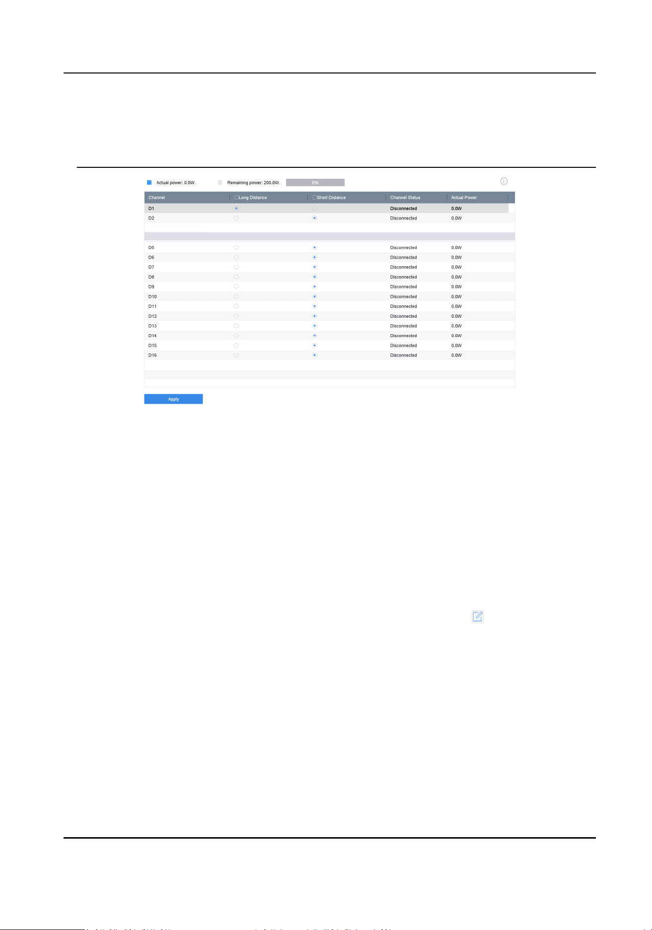
●
When the transmission distance reaches 100 to 250 meters, you must use the CAT5E or CAT6
network cable to connect with the PoE interface.
●
When the transmission distance reaches 250 to 300 meters, you must use the CAT6 network
cable to connect with the PoE interface.
Figure 1-12 Add PoE Camera
3. Click Apply.
4. Connect PoE cameras to device PoE ports with network cables.
5. Go to Camera → Camera → IP Camera to view camera image and informaon.
Add Non-PoE Network Camera
You can disable the PoE interface by selecng the manual while the current channel can be used as
a normal channel and the parameters can also be edited.
Steps
1. Go to Camera → Camera → IP Camera .
2. Posion the cursor on a window with no linked network camera and click .
Network Video Recorder User Manual
11
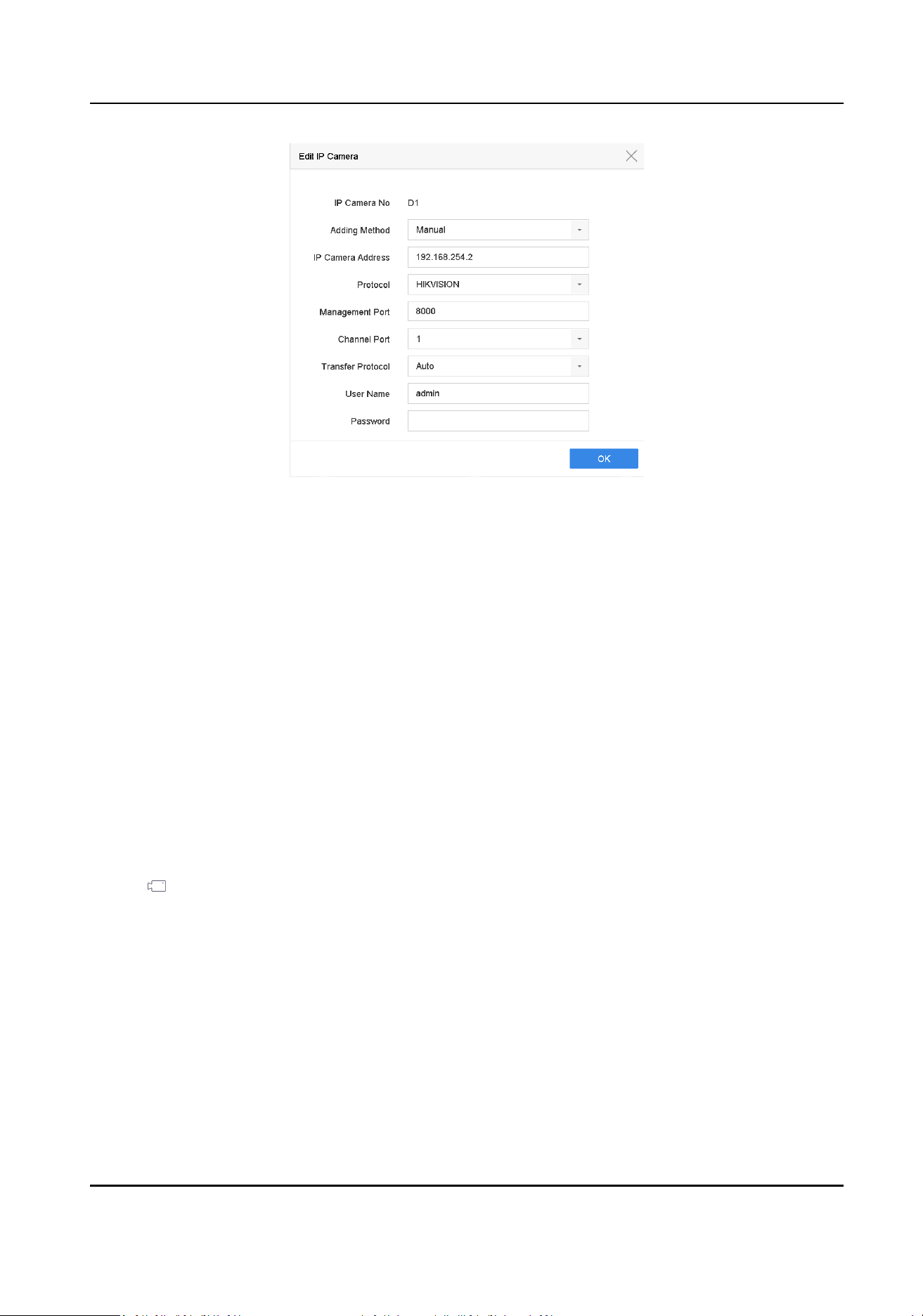
Figure 1-13 Edit Network Camera
3. Select Adding Method as Manual.
Plug-and-Play
The camera is physically connected to the PoE interface. Its parameters cannot be edited. You
can go to System → Network → TCP/IP to change IP address of PoE port.
Manual
Add IP camera without physical connecon via network.
4. Enter IP address, User Name, and Password.
5. Click OK.
1.4.4 Add Network Camera via Customized Protocol
For network cameras that are not using standard protocols, you can congure customized
protocols to add them. The system provides 8 customized protocols.
Steps
1. Click
on the main menu.
2. Go to More Sengs → Protocol .
Network Video Recorder User Manual
12

Note
3. Set protocol parameters.
Type
The network camera adopng custom protocol must support geng stream through
standard RTSP.
Path
Contact the manufacturer of network camera for the URL (Uniform Resource Locator) of
geng main stream and sub-stream.
Note
The protocol type and the transfer protocol must be supported by the network camera to add.
4. Click OK.
5. Click Custom Add to add cameras.
6. Set the parameters.
7. Click OK.
1.5 Connect to Plaorm
1.5.1 Congure ISUP
SDK is based on Intelligent Security Uplink Protocol (ISUP). It provides APIs, library les, and
commands for the third-party plaorm to access devices such as NVRs, speed domes, DVRs,
network cameras, mobile NVRs, mobile devices, decoding devices, etc. With this protocol, the
third-party plaorm can realize funcons like live view, playback, two-way audio, PTZ control, etc.
Steps
1. Go to System → Network → Advanced → Plaorm Access .
Network Video Recorder User Manual
13
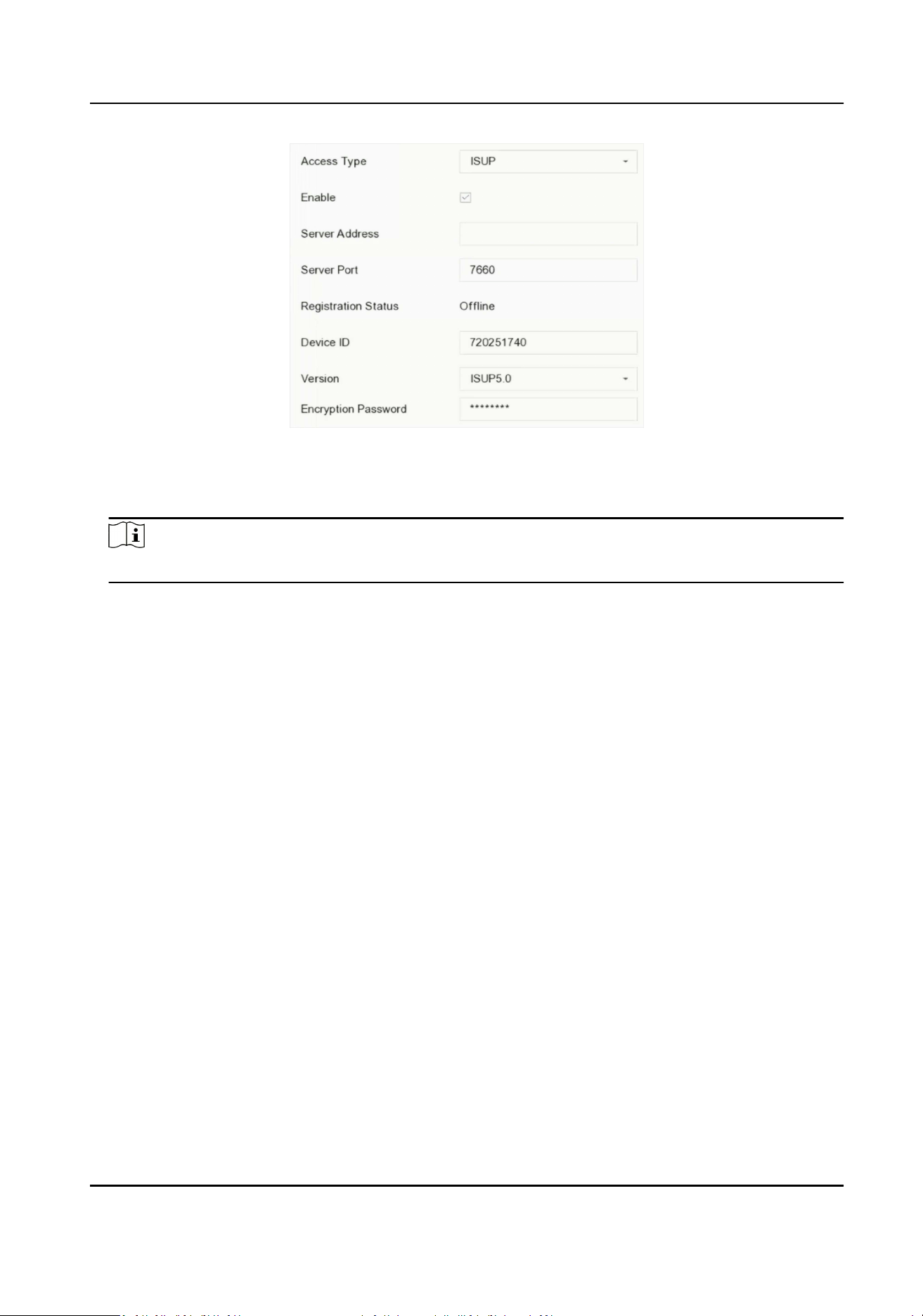
Figure 1-14 ISUP Sengs
2. Select Access Type as ISUP.
3. Check Enable.
Note
Enabling ISUP will disable other plaorm access.
4. Set the related parameters.
Server Address
The plaorm server IP address.
Server Port
The plaorm server port, ranges from 1024 to 65535. The actual port shall be provided by
the plaorm.
Device ID
Device ID shall be provided by the plaorm.
Version
ISUP protocol version, only V5.0 is available.
Encrypon Password
Encrypon password is required when using ISUP V5.0 version, it provides more secure
communicaon between the device and plaorm. Enter it for vericaon aer the device is
registered to the ISUP plaorm. It cannot be empty, or "ABCDEF".
5. Click Apply to save the sengs and restart the device.
What to do next
You can see the registraon status (online or oine) aer the device is restarted.
Network Video Recorder User Manual
14

1.5.2 Congure Hik-Connect
Hik-Connect provides mobile phone applicaon and plaorm service to access and manage your
video recorder, which enables you to get a convenient remote access to the video security system.
Steps
1. Go to System → Network → Advanced → Plaorm Access .
2. Check Enable to acvate the funcon. Then the service terms will pop up.
1) Enter Vericaon Code.
2) Scan the QR code to read the service terms and privacy statement.
3) Check The Hik-Connect service will require Internet access. Please read Service Terms and
Privacy Statement before enabling the service. if you agree with the service terms and
privacy statement.
4) Click OK.
Note
●
Hik-Connect is disabled by default.
●
The vericaon code is empty by default. It must contain 6 to 12 leers or numbers, and it is
case sensive.
3. Oponal: Congure following parameters.
●
Check Custom and enter Server Address as your desire.
●
Check Enable Stream Encrypon, then vericaon code is required for remote access and live
view.
●
Check Time Sync, and the device will sync me with Hik-Connect instead of NTP server.
4. Bind your device with a Hik-Connect account.
1) Use a smart phone to scan the QR code, and download Hik-Connect app. You can also
download it from
hps://appstore.hikvision.com , or the QR code below. Refer to Hik-
Connect Mobile Client User Manual for details.
Figure 1-15 Download Hik-Connect
2) Use Hik-Connect to scan the device QR, and bind the device.
Network Video Recorder User Manual
15

Note
If the device is already bound with an account, you can click Unbind to unbind with the
current account.
5. Click Apply.
What to do next
You can access your video recorder via Hik-Connect.
Network Video Recorder User Manual
16

Chapter 2 Camera Sengs
2.1 View Camera Error Informaon
Camera error informaon of each channel can be accessed.
If excepon occurs, camera error informaon of individual channel(s) will be provided on the
screen. Go to Camera → IP Camera , move the cursor to a window, and click to edit the
parameters of dierent channel(s).
2.2 Congure Image Parameters
You can customize image parameters, including day/night switch, backlight, contrast, and
saturaon in Camera → Display .
Image Sengs
Customize the image parameters including brightness, contrast, and saturaon.
Exposure
Set the camera exposure me (1/10000 to 1 sec). A larger exposure value results in a brighter
image.
Day/Night Switch
Set the camera to day, night, or auto switch mode according to me or the surrounding
illuminaon condion. When the light diminishes at night, the camera can switches to night
mode with high quality black and white image.
Backlight
Set the camera's wide dynamic range (0 to 100). When the surrounding illuminaon and the
object have large dierences in brightness, you can set the WDR value to balance the brightness
level of the whole image.
Image Enhancement
For opmized image contrast enhancement that reduces noise in video stream.
2.3 Congure OSD
You can congure the OSD (On-screen Display) for the camera, including date/me, camera name,
etc.
Steps
1. Go to Camera → Display .
2. Select a camera as your desire.
3. Edit name in Camera Name.
Network Video Recorder User Manual
17
4. Check Display Name, Display Date and Display Week to show the informaon on the image.
5. Set the date format, me format, and display mode.
Figure 2-1 OSD Sengs
6. Drag the text frame on the preview window to adjust the OSD posion.
7. Click Apply.
2.4 Congure Privacy Mask
The privacy mask protects personal privacy by concealing parts of the image from kive view or
recording with a masked area.
Steps
1. Go to Camera → Privacy Mask .
2. Select a camera to set privacy mask.
3. Check Enable.
4. Draw a zone on the window. The zone will be marked by dierent frame colors.
Network Video Recorder User Manual
18
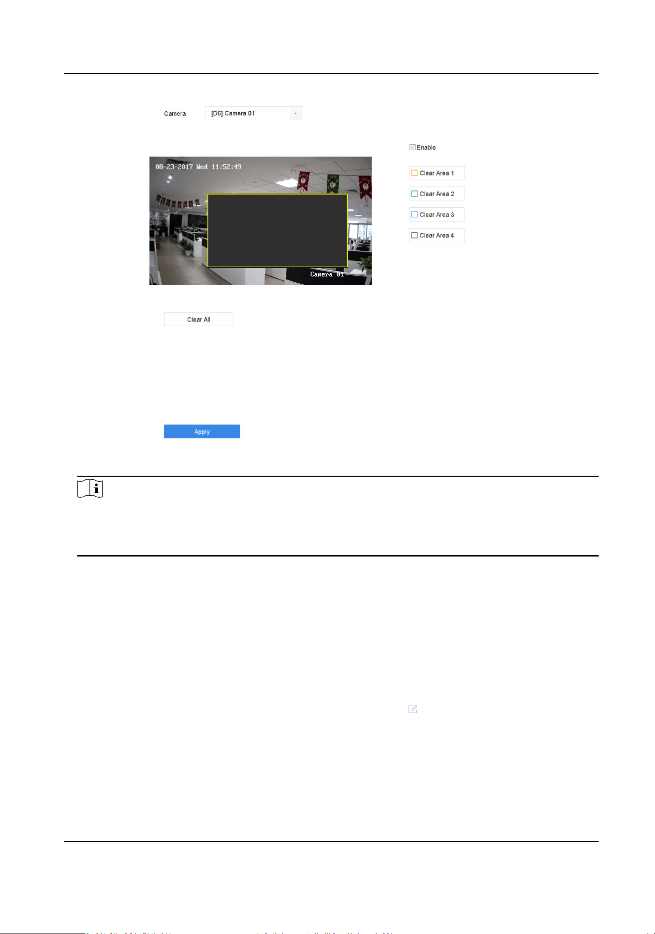
Figure 2-2 Privacy Mask Sengs
Note
●
Up to 4 privacy masks zones can be congured and the size of each area can be adjusted.
●
You can clear the congured privacy mask zones on the window by clicking the corresponding
clear zone 1 to 4 icons on the right of the window, or click Clear All to clear all zones.
5. Click Apply.
2.5 IP Camera Time Sync
The device can automacally synchronize the me of connected IP camera aer enabling this
funcon.
Steps
1. Go to Camera → Camera → IP Camera .
2. Posion the cursor on the window of the IP camera and click
.
3. Check Enable IP Camera Time Sync.
4. Click OK.
5. Oponal: All IPC channels can be enabled/disabled with shortcuts.
1) Go to Maintenance → System Service → More Sengs .
Network Video Recorder User Manual
19

2) Click Time Sync Conguraon, select Enable IPC Time Sync or Disable IPC Time Sync to
enable/disable scheduled me sync for all IPC/IoT channels.
Figure 2-3 IP Camera Time Sync
Note
This funcon is only available for the admin user.
2.6 Import Network Camera Cercate
Import the network camera cercate to the video recorder.
Steps
1. Log in the network camera via web browser.
2. Go to Conguraon → Network → Advanced Sengs → HTTPS on the web browser to export
its cercate.
3. Click Export at Export Cercate to save the cercate.
4. Log in the video recorder by web browser.
5. Go to Conguraon → System → Security → Trusted Root Cercaon Authories → Import .
6. Click Import to import the network camera cercate.
2.7 Import/Export IP Camera Conguraon Files
The IP camera informaon, including the IP address, manage port, password of admin, etc., can be
saved in Microso Excel format and backed up to the local device. The exported le can be edited
on a PC, including adding or deleng the content, and copying the seng to other devices by
imporng the Excel le to it.
Network Video Recorder User Manual
20
Before You Start
When imporng the conguraon le, connect the storage device that contains the conguraon
le to the device.
Steps
1. Go to Camera → IP Camera Import/Export .
2. Click IP Camera Import/Export, and the detected external device contents appear.
3. Export or import the IP camera conguraon les.
-
Click Export to export the conguraon les to the selected local backup device.
-
To import a conguraon le, select the le from the selected backup device and click Import.
Note
Aer the imporng process is completed, you must reboot the device to acvate the sengs.
2.8 Save Camera VCA Data
Aer saving camera VCA data to your device, you will be able to search the camera VCA data.
Go to Storage → Advanced to enable Save VCA Data via local GUI interface.
Go to Conguraon → Video and Audio → Display Info. on Scream to turn on Enable Dual-VCA
via web browser.
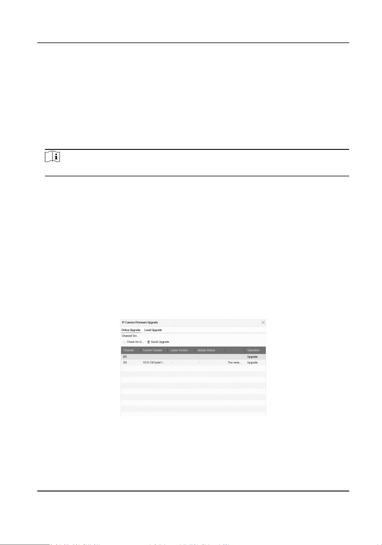
2.9 Upgrade IP Cameras
The IP camera can be upgraded through the device.
Steps
1. Go to Camera → Camera → IP Camera → More Sengs → Upgrade .
Figure 2-4 Upgrade IP Cameras
2. Select a method to upgrade your camera.
Online
Upgrade
Click Online Upgrade, and click Check for Updates or Quick Upgrade to
upgrade your cameras.
Network Video Recorder User Manual
21

Note
Your device shall be properly connected to Hik-Connect.
Local
Upgrade
Inserted a USB ash drive that contains the rmware to your device. Click
Local Upgrade, and select the camera and rmware le for upgrade.
The IP camera will automacally restart aer it is upgraded.
3. Click Upgrade.
Network Video Recorder User Manual
22

Chapter 3 Live View
Live view displays the video image geng from each camera in real me.
3.1 Start Live View
Click on the main menu bar.
●
Select a window and double click a camera from the channel list to play the live image of the
camera.
●
Double click a window to view it in single-screen mode. Double click again to exit single-screen
mode.
●
Use the toolbar at the playing window boom to realize the capture, instant playback, audio on/
o, digital zoom, live view strategy, show informaon and start/stop recording, etc.
Note
○
Click at the lower right corner to stop all-day connuous recordings.
○
If you have added audio device(s) to the recorder, you can move the cursor to to select an
audio source. But this selecon is used for live view only, it will not aect the audio recording
sengs.
●
Click to start/stop auto-switch. The screen will automacally switch to the next one.
●
Single click to enable VCA informaon display. Double click to disable VCA informaon
display.
Note
Click at the lower right corner to enable/disable VCA informaon display for all channels. VCA
informaon of 16 channels (maximum) is available.
●
Move the cursor to a window, and right click your mouse to display the shortcut menu of the
window. The shortcut menu will be dierent according to the window.
Network Video Recorder User Manual
23
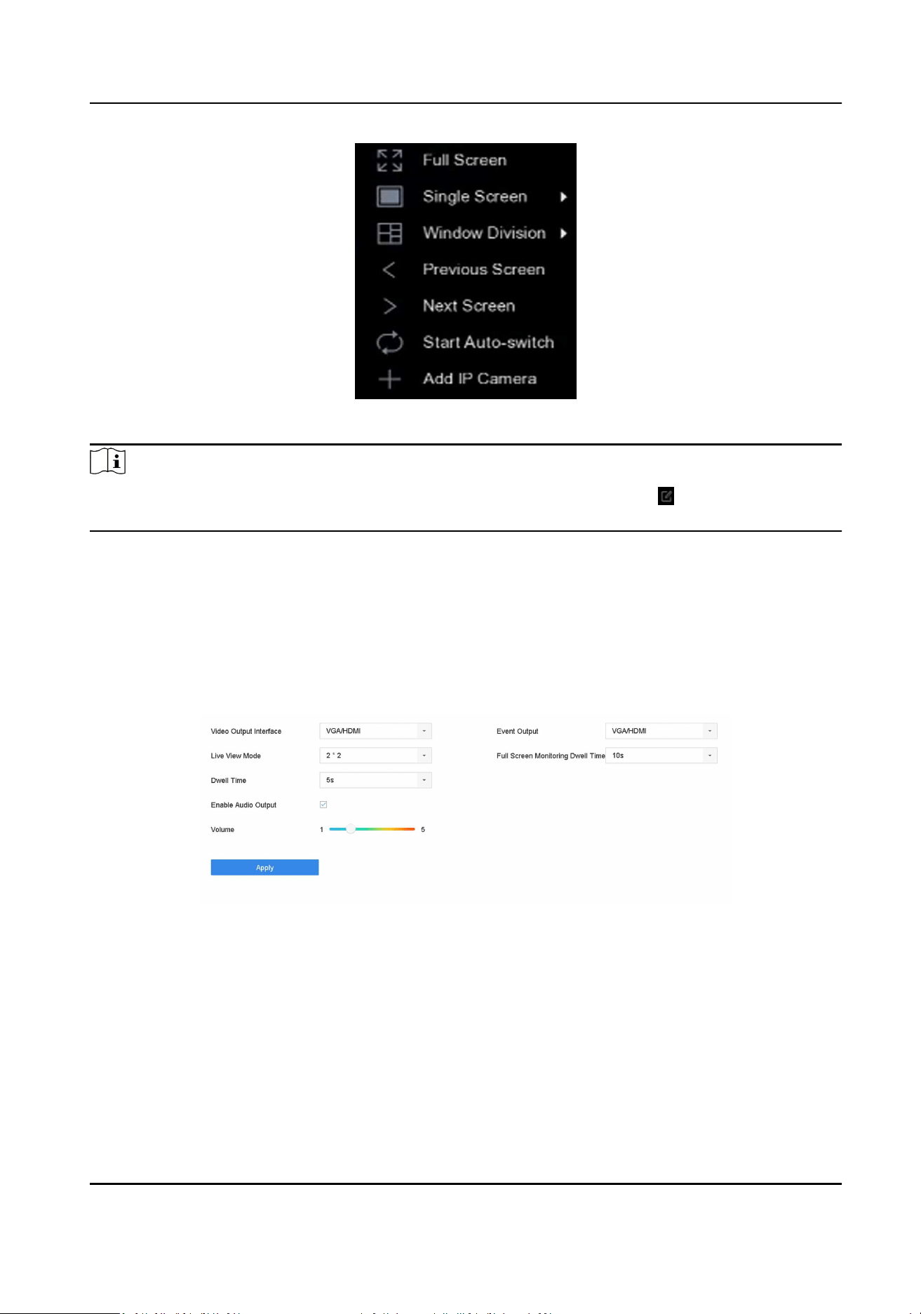
Figure 3-1 Shortcut Menu
Note
If excepon occurs, error informaon will be displayed on the screen. Click to edit the
parameters of dierent channel(s).
3.2 Congure Live View Sengs
Live View sengs can be customized. You can congure the output interface, dwell me for screen
to be shown, mute or turning on the audio, the screen number for each channel, etc.
Steps
1. Go to System → Live View → General .
Figure 3-2 Live View-General
2. Congure the live view parameters.
Video Output Interface
Select the video output to congure.
Live View Mode
Select the display mode for Live View, e.g., 2*2, 1*5, etc.
Dwell Time
Network Video Recorder User Manual
24

The me in seconds to wait between switching of cameras when using auto-switch in Live
View.
Enable Audio Output
Enable/disable audio output for the selected video output.
Volume
Adjust the Live View volume, playback and two-way audio for the selected output interface.
Event Output
Select the output to show event video.
Full Screen Monitoring Dwell Time
Set the me in seconds to show alarm event screen.
3. Click OK.
3.3 Congure Auto-Switch of Cameras
You can set the auto-switch of cameras to play in dierent display modes.
Steps
1. Go to System → Live View → General .
2. Set Video Output Interface, Live View Mode, and Dwell Time.
Video Output Interface
Select the video output interface.
Live View Mode
Select the display mode for live view, e.g., 2*2, 1*5, etc.
Dwell Time
The me in seconds to dwell between switching of cameras when enabling auto-switch. The
range is from 5s to 300s.
3. Go to View Sengs to set the view layout.
4. Click OK to save the sengs.
3.4 Congure Live View Layout
Live view displays the video image geng from each camera in real me.
3.4.1 Congure Custom Live View Layout
Steps
1. Go to System → Live View → View .
2. Click Set Custom Layout.
3. Click on the Custom Layout Conguraon interface.
Network Video Recorder User Manual
25

4. Edit the layout name.
5. Select a window division mode from the toolbar.
Figure 3-3 Congure Live View Layout
6. Select mulple windows and click to joint the windows. The selected windows must be in
rectangle area.
7. Click Save.
The successfully congured layout is displayed in the list.
8. Oponal: Select a live view layout from the list and click to edit the name, or click to
delete the name.
3.4.2 Congure Live View Mode
Steps
1. Go to System → Live View → View .
2. Select the video output interface.
3. Select a layout or custom layout from the toolbar.
4. Select a division window, and double-click on a camera in the list to link the camera to the
window.
Note
●
You can also click-and-drag the camera to the desired window on the Live View interface to
set the camera order.
●
You can enter the number in the text eld to quickly search the camera from the list.
5. Click Apply.
6. Oponal: Click to start live view for all channels, or click to stop all live view channels.
Network Video Recorder User Manual
26
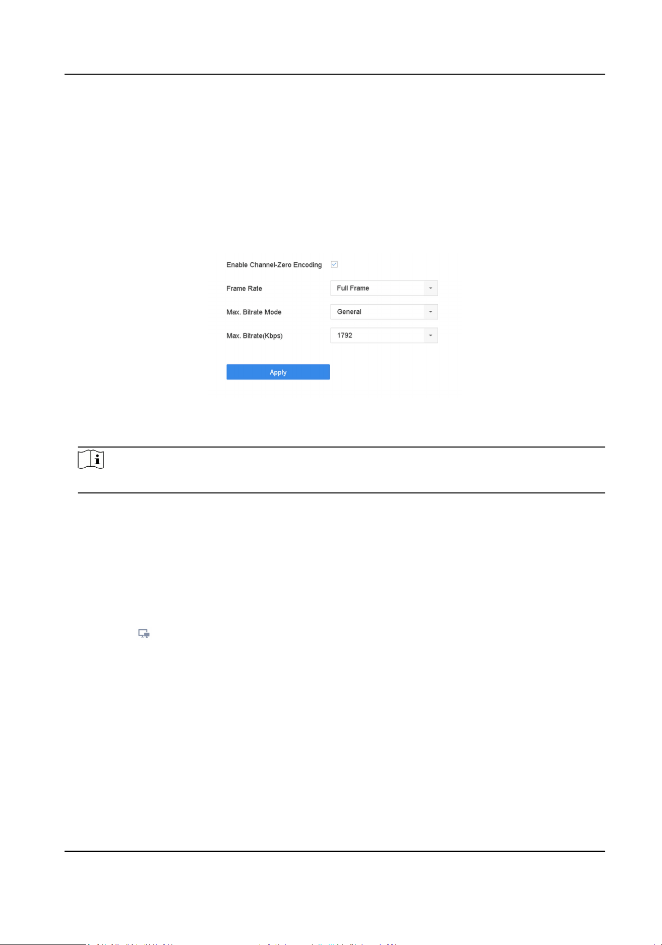
3.5 Congure Channel-Zero Encoding
Enable the channel-zero encoding when you need to get a remote view of many channels in real
me from a web browser or CMS (Client Management System) soware, in order to decrease the
bandwidth requirement without aecng the image quality.
Steps
1. Go to System → Live View → Channel-Zero .
2. Check Enable Channel-Zero Encoding.
Figure 3-4 Channel-Zero Encoding
3. Congure Frame Rate, Max. Bitrate Mode, and Max. Bitrate.
Note
The higher frame rate and bitrate require the higher bandwidth.
4. Click Apply.
You can view all the channels on one screen via CMS or web browser.
3.6 Main and Auxiliary Ports Strategy
There are ve video output types: HDMI, VGA, LCD, HDMI2, and CVBS. Priority of video outputs:
HDMI > VGA/LCD > HDMI2.
You can click in Live View mode, or go to System → General to switch the main/auxiliary port
For iDS-9600NXI-I8/4F(B) series, HDMI1 and VGA are simultaneous output, HDMI1, VGA, HDMI2,
CVBS cannot provide video output at the same me. When HDMI1, HDMI2, VGA, and CVBS are all
connected, CVBS does not provide video output, the main port is HDMI2, and the aux port is
HDMI1 and VGA. You can enable CVBS in System → General , it requires to switch menu output
mode to HTMI2, and disable HDMI1/VGA.
For other series, the following table shows the main and auxiliary ports strategy when video cables
for HDMI, HDMI2, and VGA are connected.
Main port
All operaons are available for main port.
Network Video Recorder User Manual
27

Aux port
You can switch to aux port to do some basic operaons, like playback, switching live view image.
Third port
You can only preview camera image in third port.
Table 3-1 Main and Auxiliary Ports Strategy
HDMI/VGA/LCD
simultaneous
output
Menu output
mode
HDMI HDMI2 VGA/LCD
On Auto Main port Aux port Main port
O Auto Main port Aux port Third port
On HDMI2 Aux port Main port Aux port
O HDMI2 Aux port Main port Third port
On HDMI/VGA/LCD Main port Aux port Main port
O VGA/LCD Aux port Third port Main port
HDMI Main port Third port Aux port
3.7 Digital Zoom
Digital Zoom zooms into the live image in dierent magnicaons (1x to 16x).
Steps
1. Start live view.
2. Click from the toolbar.
3. Move the sliding bar or scroll the mouse wheel to zoom in/out the image to dierent
magnicaons (1x to 16x).
Network Video Recorder User Manual
28
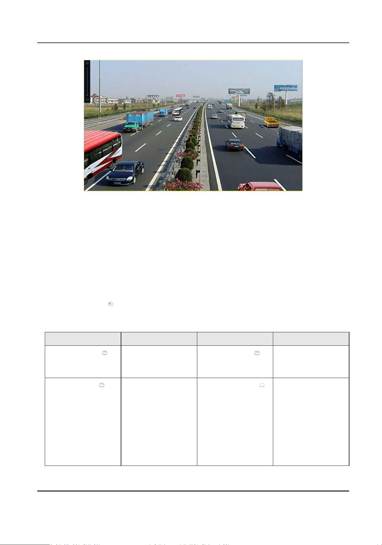
Figure 3-5 Digital Zoom
3.8 Fisheye View
The device supports the sheye camera expansion in Live View or playback mode.
Before You Start
●
The sheye expansion view feature is supported only by certain models.
●
The connected camera must support the sheye view.
Steps
1. Start live view, click
to enter the sheye expansion mode.
2. Select the expansion view mode.
Table 3-2 Fisheye View Icon Descripon
Icon Descripon Icon Descripon
180° Panorama ( ) Switch the Live View
image to the 180°
panorama view.
360° Panorama ( ) Switch the Live View
image to the 360°
panorama view.
PTZ Expansion ( ) The PTZ Expansion is
the close-up view of
some dened area in
the sheye view or
panorama expansion.
It supports the
electronic PTZ
funcon, also called e-
PTZ.
Radial Expansion ( ) In radial expansion
mode, the whole
wide-angle view of the
sheye camera is
displayed. This view
mode is called Fisheye
View because it
approximates the
Network Video Recorder User Manual
29

Icon Descripon Icon Descripon
vision of a sh’s
convex eye. The lens
produces curvilinear
images of a large area,
while distorng the
perspecve and
angles of objects in
the image.
3.9 3D Posioning
3D Posioning zooms in/out a specic live image area.
Steps
1. Start live view, and click .
2. Zoom in/out the image.
-
Zoom in: Click on the desired posion in the video image and drag a rectangle area in the
lower right direcon to zoom in.
-
Zoom out: Drag a rectangle area in the upper le direcon to move the posion to the center
and enable the rectangle area to zoom out.
3.10 Live View Strategy
Steps
1. In the live view mode, click
to enter the digital zoom operaon interface in full screen mode.
2. Select the live view strategy to Real-me, Balanced or Fluency.
3.11 Person Passing
You can view real-me facial recognion and stranger recognion results.
Before You Start
Ensure you have congured facial detecon and face picture comparison funcon, refer to Face
Picture Comparison for details.
Steps
Note
This funcon is only available for certain models
Network Video Recorder User Manual
30
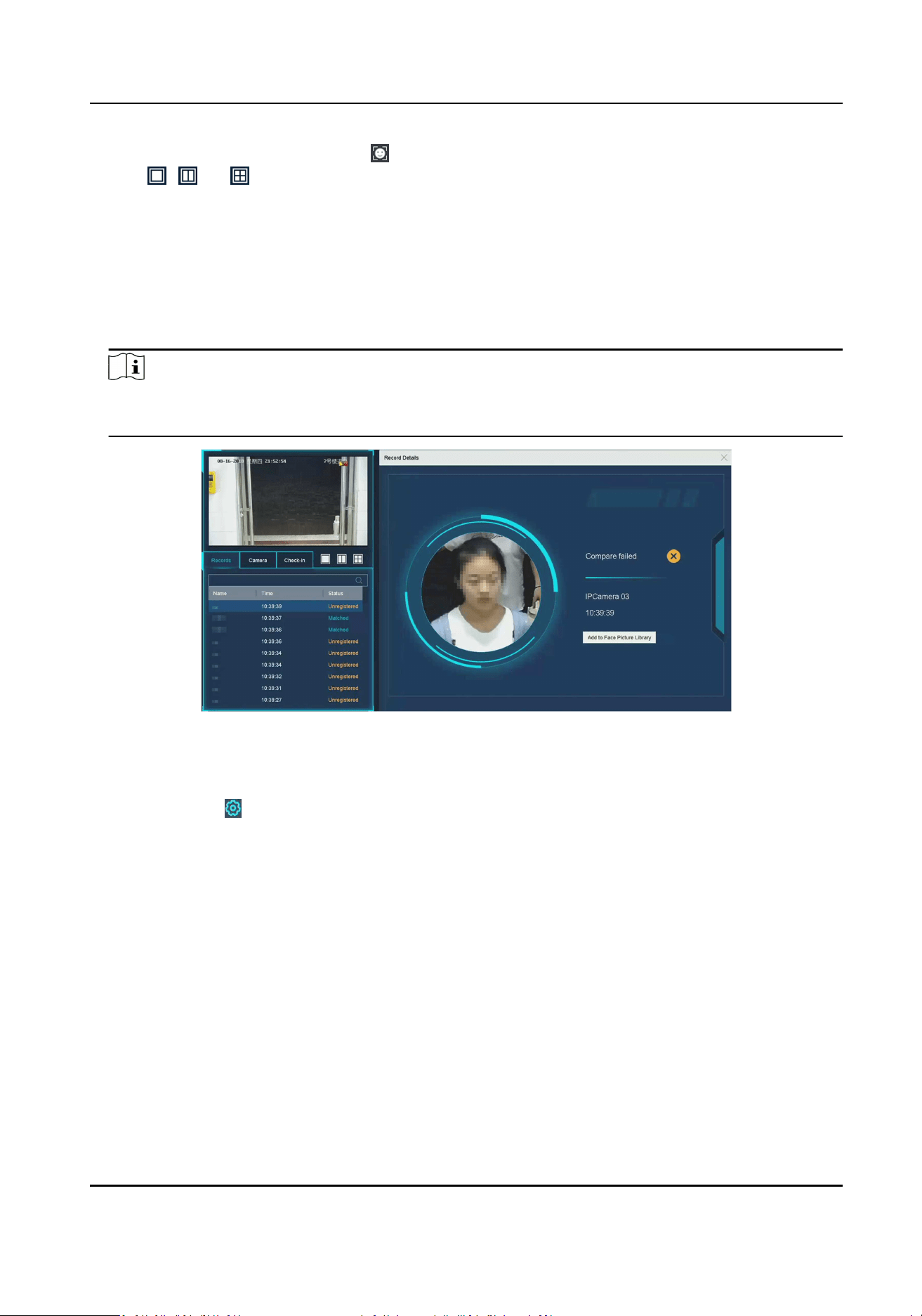
1. Go to live view interface, and click in toolbar.
2. Click , , or to set window division.
3. Select a window as you desired.
4. Double click a camera from the camera list on the le boom.
5. Click Records to view the real-me person passing records of selected camera. The records will
also be shown in the window on the right. You can view the facial detecon number at the top,
including the total number, succeeded number and failed number.
6. Oponal: For the unregistered face picture, you can double click it in records list, and add it to
face picture library.
Note
For guest and operator user, it requires Local Parameters Sengs permission to add
unregistered face picture to face picture library.
Figure 3-6 Add Unregistered Face Picture
7. Oponal: Click Check-in to view face picture library check-in record, including Total No.,
Checked In and Unchecked In.
8. Oponal: Click on the upper right corner to congure the display sengs as you desired.
Network Video Recorder User Manual
31
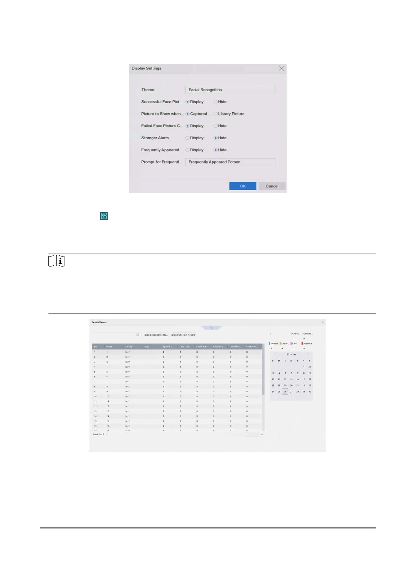
Figure 3-7 Person Passing Display Sengs
9. Oponal: Click on the upper right corner to search and export record.
1) Set the search parameters as you desired.
2) Click Search.
3) Click Export Aendance Record or Export Check-in Record.
Note
●
Ensure you have inserted USB ash drive before export.
●
You can click a record to review the aendance informaon of this individual in calendar.
●
For guest and operator user, it requires "Local Video Export permission" (in "Camera
Permission") to search and export record.
Figure 3-8 Person Passing Search Record
Network Video Recorder User Manual
32
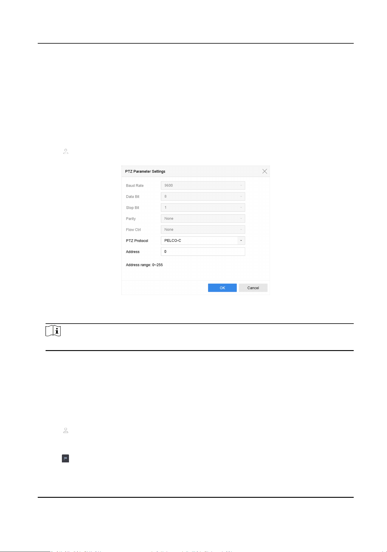
3.12 PTZ Control
3.12.1 Congure PTZ Parameters
Follow these procedures to set the PTZ parameters. The PTZ parameters conguraon must be
done before you can control the PTZ camera.
Steps
1. Click on the quick sengs toolbar of the PTZ camera.
2. Click PTZ Parameters Sengs to set the PTZ parameters.
Figure 3-9 PTZ Parameters Sengs
3. Edit the PTZ parameters.
Note
All the parameters should be exactly match the PTZ camera parameters.
4. Click OK to save the sengs.
3.12.2 Set a Preset
Presets record the PTZ posion and the status of zoom, focus, iris, etc. You can call a preset to
quickly move the camera to the predened posion.
Steps
1. Click on the quick sengs toolbar of the PTZ camera's live view.
2. Click direconal buons to wheel the camera to a locaon.
3. Adjust the zoom, focus and iris status.
4. Click in the lower right corner of Live View to set the preset.
Network Video Recorder User Manual
33
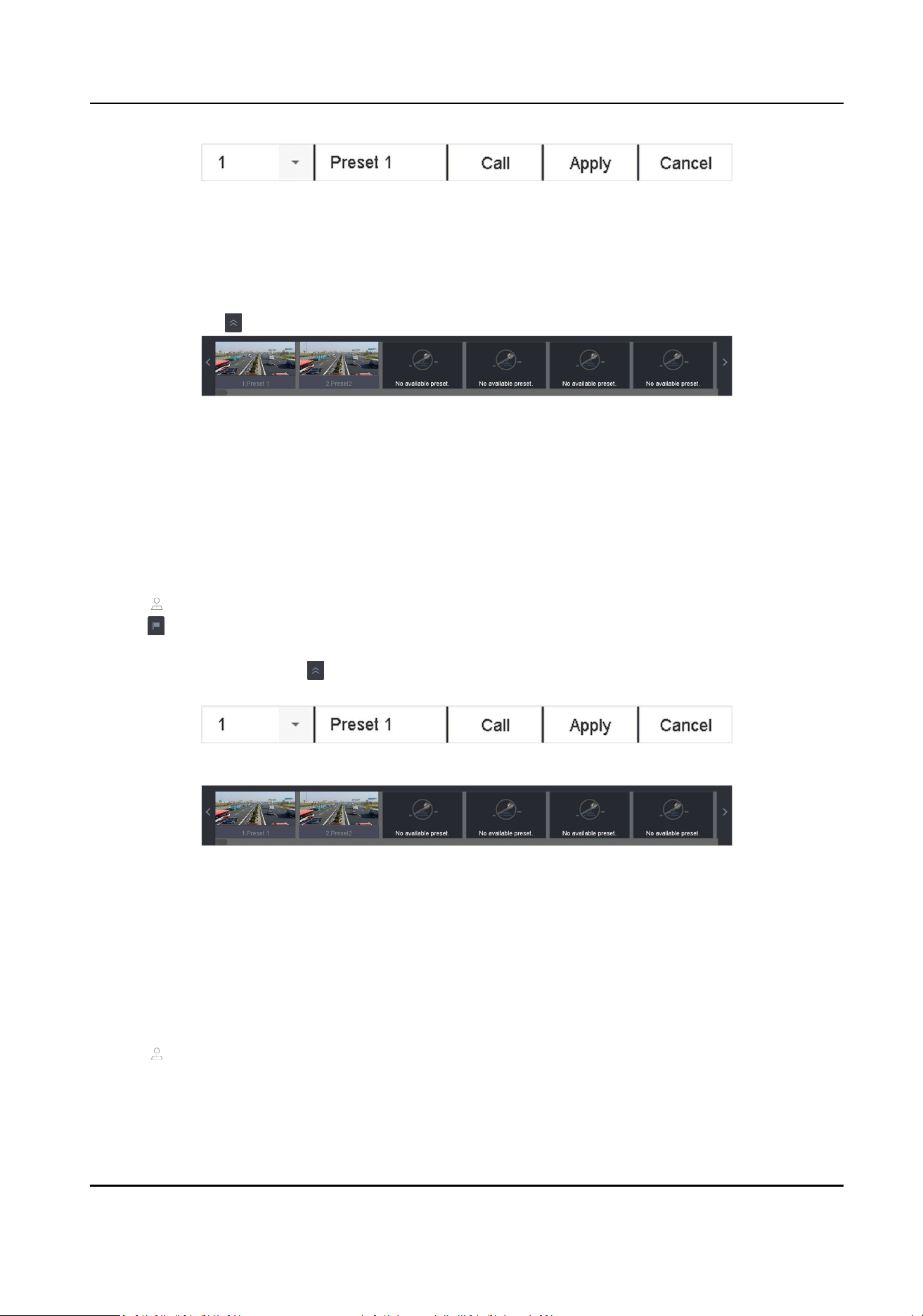
Figure 3-10 Set Preset
5. Select the preset No. (1 to 255) from the drop-down list.
6. Enter the preset name.
7. Click Apply to save the preset.
8. Oponal: Click Cancel to cancel the locaon informaon of the preset.
9. Oponal: Click in the lower right corner of Live View to view the congured presets.
Figure 3-11 View the Congured Presets
3.12.3 Call a Preset
A preset enables the camera to point to a specied posion such as a window when an event takes
place.
Steps
1. Click on the quick sengs toolbar of the PTZ camera's Live View.
2. Click in the lower right corner of Live View to set the preset.
3. Select the preset No. from the drop-down list.
4. Click Call to call it, or click in the lower right corner of Live View, and click the congured
preset to call it.
Figure 3-12 Call Preset (1)
Figure 3-13 Call Preset (2)
3.12.4 Set a Patrol
Patrols can be set to move the PTZ to key points and have it stay there for a set duraon before
moving on to the next key point. The key points are correspond to the presets.
Steps
1. Click on the quick sengs toolbar of the PTZ camera's live view.
2. Click Patrol to congure patrol.
Network Video Recorder User Manual
34
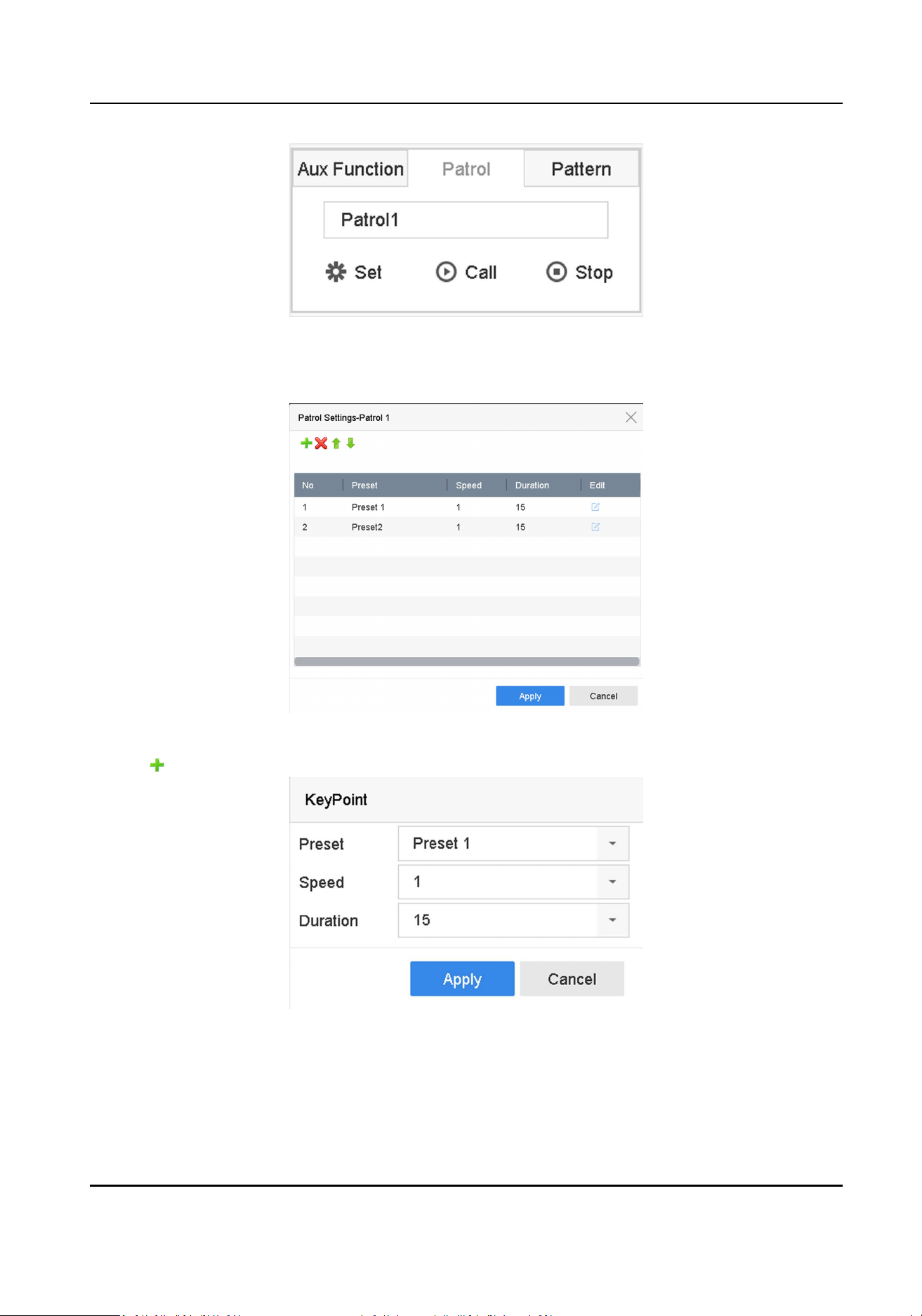
Figure 3-14 Patrol Conguraon
3. Select the patrol No.
4. Click Set.
Figure 3-15 Patrol Sengs
5. Click to add a key point to the patrol.
Figure 3-16 Key Point Conguraon
1) Congure key point parameters.
Preset
Network Video Recorder User Manual
35
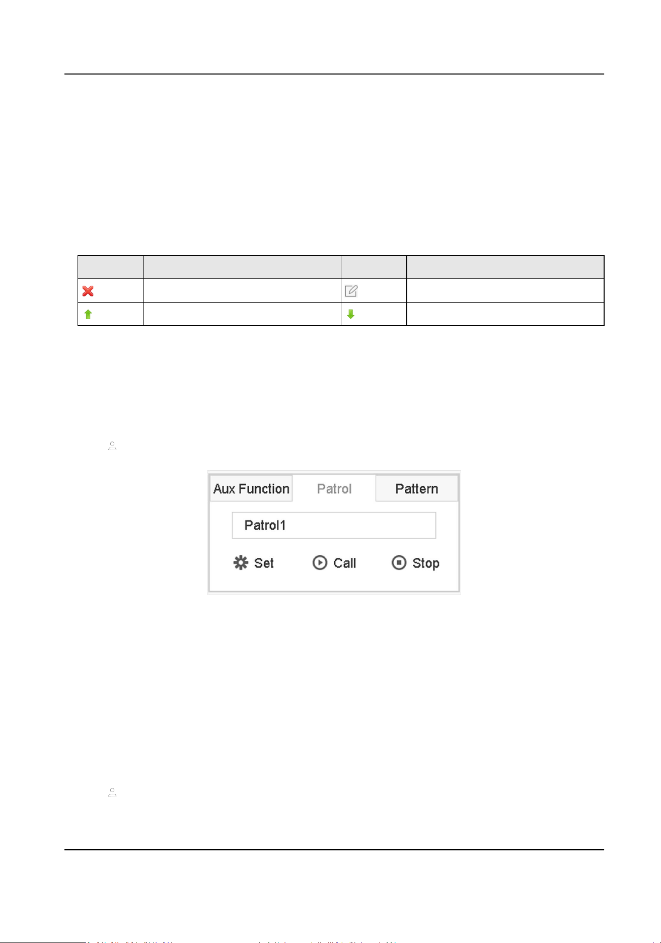
Determines the order the PTZ will follow while cycling through the patrol.
Speed
Denes the speed the PTZ will move from one key point to the next.
Duraon
Refers to the duraon to stay at the corresponding key point.
2) Click Apply to save the key points to the patrol.
6. Other operaon is as follows.
Table 3-3 Operaon Descripon
Operaon Descripon Operaon Descripon
Select a key point to delete. Edit the added key point.
Adjust the key point order Adjust the key point order
7. Click Apply to save the patrol sengs.
3.12.5 Call a Patrol
Calling a patrol makes the PTZ move according to the predened patrol path.
Steps
1. Click on the quick sengs toolbar of the PTZ camera's live view.
2. Click Patrol on the PTZ control panel.
Figure 3-17 Patrol Conguraon
3. Select a patrol.
4. Click Call to start the patrol.
5. Oponal: Click Stop to stop the patrol.
3.12.6 Set a Paern
Paerns can be set by recording the movement of the PTZ. You can call the paern to make the
PTZ move according to the predened path.
Steps
1. Click on the quick sengs toolbar of the PTZ camera's live view.
Network Video Recorder User Manual
36
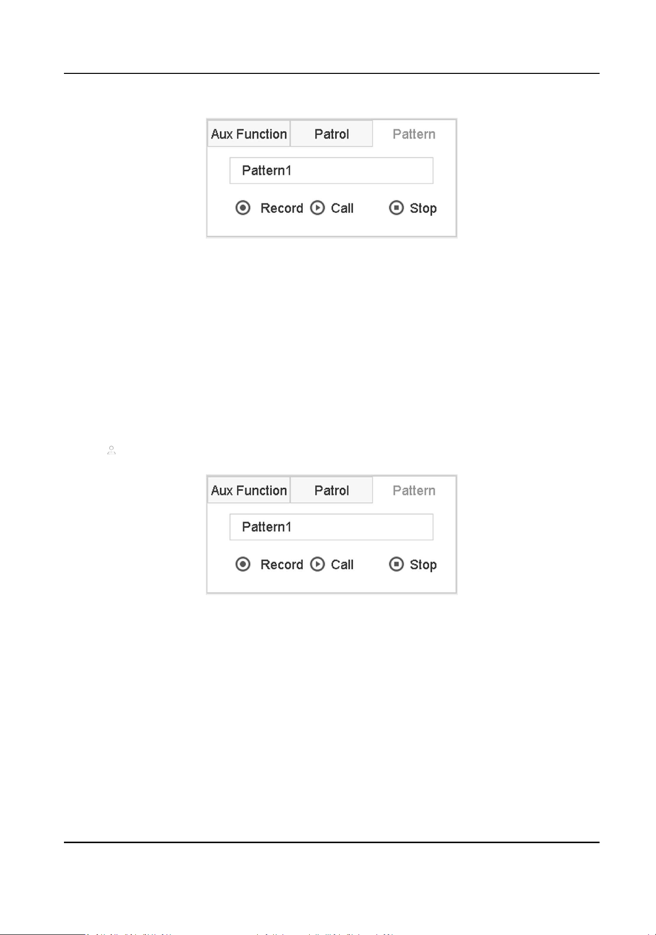
2. Click Paern to congure a paern.
Figure 3-18 Paern Conguraon
3. Select the paern No.
4. Set the paern.
1) Click Record to start recording.
2) Click corresponding buons on the control panel to move the PTZ camera.
3) Click Stop to stop recording. The PTZ movement is recorded as the paern.
3.12.7 Call a Paern
Follow the procedure to move the PTZ camera according to the predened paerns.
Steps
1. Click on the quick sengs toolbar of the PTZ camera's live view.
2. Click Paern to congure paern.
Figure 3-19 Paern Conguraon
3. Select a paern.
4. Click Call to start the paern.
5. Oponal: Click Stop to stop the paern.
3.12.8 Set Linear Scan Limit
Linear Scan trigger a scan in the horizontal direcon in the predened range.
Before You Start
Make sure the connected IP camera supports the PTZ funcon and is properly connected.
Network Video Recorder User Manual
37

Note
This funcon is supported only by certain models.
Steps
1. Click on the quick sengs toolbar of the PTZ camera's live view.
2. Click direconal buons to wheel the camera to a locaon, and click Le Limit or Right Limit to
link the locaon to the corresponding limit.
Note
The speed dome linear scans from the le limit to the right limit, and you must set the le limit
on the le side of the right limit. Also, the angle from the le limit to the right limit must be not
greater than 180º.
3.12.9 One-Touch Park
Certain speed dome models can be congured to start a predened park acon (scan, preset,
patrol, etc.) automacally aer a period of inacvity (park me).
Before You Start
Before operang this funcon, make sure the connected camera supports linear scan and is in
HIKVISION protocol.
Steps
1. Click
on the quick sengs toolbar of the PTZ camera's live view.
2. Click Park (Quick Patrol), Park (Patrol 1), or Park (Preset 1) to acvate the park acon.
Park (Quick Patrol)
The dome starts patrolling from the predened preset 1 to preset 32 in order aer the park
me. Undened presets will be skipped.
Park (Patrol 1)
The dome starts moving according to the predened patrol 1 path aer the park me.
Park (Preset 1)
The dome moves to the predened preset 1 locaon aer the park me.
Note
The park me can be set only via the speed dome conguraon interface. The default value is 5s
by default.
3. Oponal: Click Stop Park (Quick Patrol), Stop Park (Patrol 1), or Stop Park (Preset 1) to
inacvate it.
Network Video Recorder User Manual
38
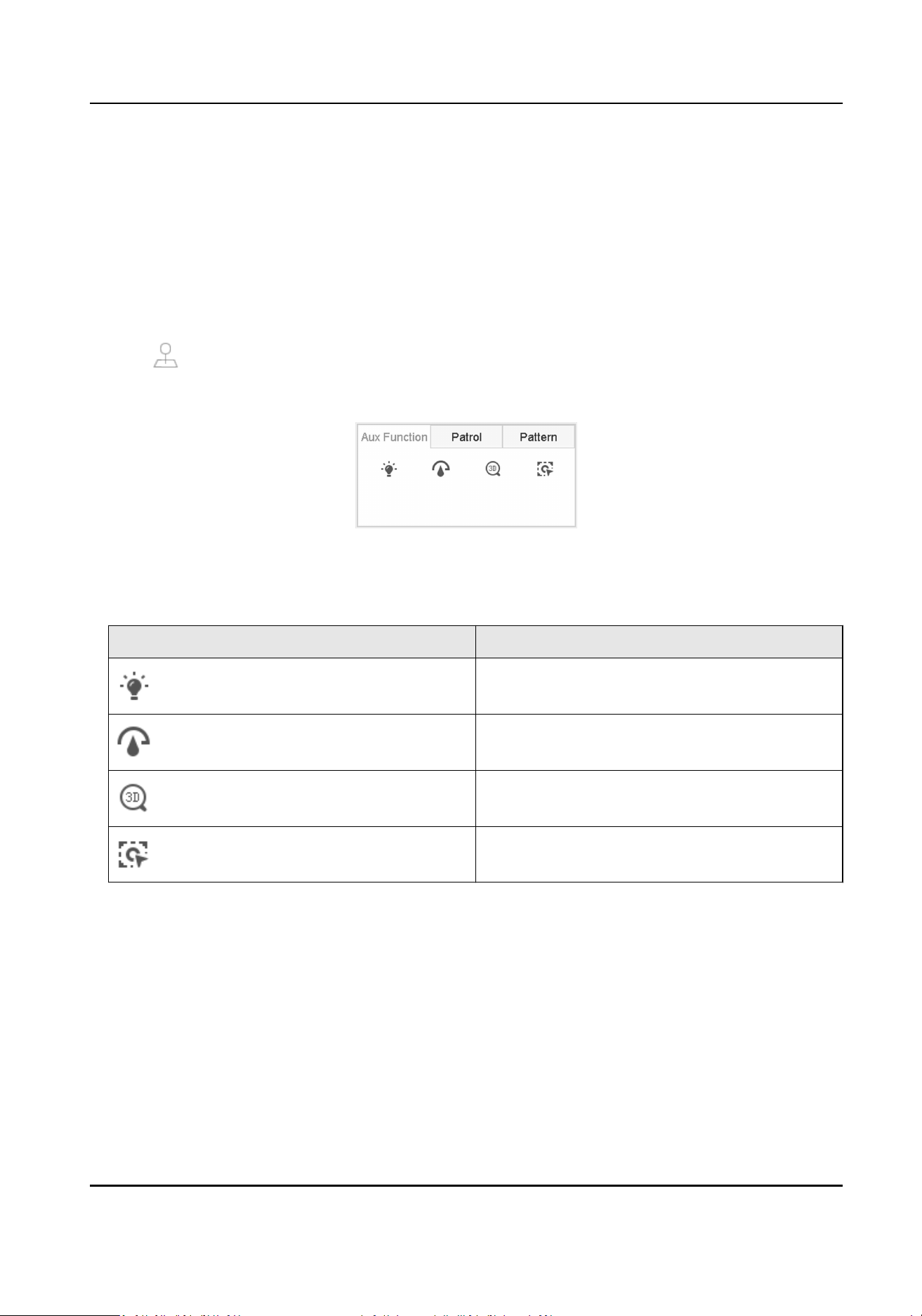
3.12.10 Auxiliary Funcons
You can operate the auxiliary funcons including light, wiper, 3D posioning, and center on the PTZ
control panel.
Before You Start
Make sure the connected IP camera supports the PTZ funcon, and is properly connected.
Steps
1.
Click on the quick sengs toolbar of the PTZ camera's live view. The PTZ control panel
displays on the right of the interface.
2. Click Aux Funcon.
Figure 3-20 Aux Funcon Conguraon
3. Click the icons to operate the aux funcons. See the table for the icon descripons.
Table 3-4 Descripon of Aux Funcons Icons
Icon Descripon
Light on/o
Wiper on/o
3D posioning
Center
Network Video Recorder User Manual
39

Chapter 4 Recording and Playback
4.1 Recording
4.1.1 Congure Recording Parameters
Congure Video Parameters
Go to Camera → Video Parameters .
Main Stream
Main stream refers to the primary stream that aects data recorded to the hard disk drive and will
directly determine your recording quality and image size.
Comparing with the sub-stream, the main stream can provide a higher quality video with higher
resoluon and frame rate.
Frame Rate (FPS - Frames per Second)
It refers to the number of frames captured each second. A higher frame rate is advantageous
when there is movement in the video stream, as it maintains image quality throughout.
Resoluon
Image resoluon is a measure of how much detail a digital image can hold. The greater the
resoluon, the greater the level of detail. Resoluon can be specied as the number of pixel-
columns (width) by the number of pixel-rows (height), e.g., 1024 × 768.
Bitrate Type
The bit rate (in kbit/s or Mbit/s) is oen referred to as speed, but actually denes the number of
bits/me unit rather than distance/me unit. Two types including variable or constant are
available.
Enable H.265+
H.265+ is an opmized encoding technology based on the standard H.265/HEVC compression.
With H.265+, the video quality is almost the same as that of H.265/HEVC but with less
transmission bandwidth and storage capacity required.
Note
●
A higher resoluon, frame rate and bit rate seng will oer you beer video quality, but it will
also require more internet bandwidth and use more storage space on the hard disk drive.
●
H.265+ encoding technology is only available for certain models.
Network Video Recorder User Manual
40
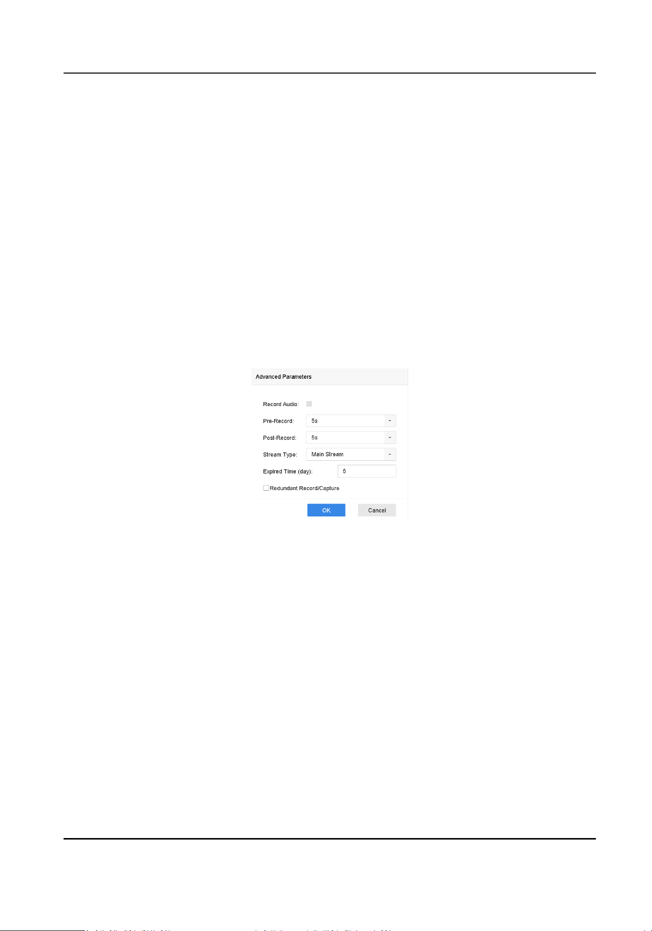
Sub-Stream
Sub-stream is a second code that runs alongside the main stream. It allows you to reduce the
outgoing internet bandwidth without sacricing your direct recording quality.
Sub-stream is oen exclusively used by apps to view live video. Users with limited internet speeds
may benet most from this seng.
Video Quality
Set the video quality as you desire. The higher video quality results in more storage space
requirement.
Congure Advanced Parameters
Steps
1. Go to Storage → Schedule → Record .
2. Check Enable Schedule to enable scheduled recording.
3. Click Advanced to set the advanced parameters.
Figure 4-1 Advanced Record Sengs
Record Audio
Enable or disable audio recording.
Pre-record
The me you set to record before the scheduled me or event. For example, when an alarm
triggers the recording at 10:00, and if you set the pre-record me as 5 seconds, the camera
records at 9:59:55.
Post-record
The me you set to record aer the event or the scheduled me. For example, when an
alarm triggered recording ends at 11:00, and if you set the post-record me as 5 seconds, it
records ll 11:00:05.
Stream Type
Main stream and sub-stream are selectable for recording. When you select sub-stream, you
can record for a longer me with the same storage space.
Network Video Recorder User Manual
41

Expired Time
The expired me is period for a recorded le to be kept in the HDD. When the deadline is
reached, the le will be deleted. If you set the expired me to 0, the le will not be deleted.
The actual keeping me for the le should be determined by the capacity of the HDD.
Redundant Record/Capture
By enabling redundant record or capture you save the record and captured picture in the
redundant HDD.
4.1.2 Enable H.265 Stream Access
The device can automacally switch to the H.265 stream of IP camera (which supports H.265 video
format) for the inial access.
Go to Camera → More Sengs → H.265 Auto Switch Conguraon to enable the funcon.
4.1.3 ANR
ANR (Automac Network Replenishment) can automacally enable SD card of network camera to
save the video in the condion of network disconnecon, and can synchronize data aer the
network is recovered.
Before You Start
●
Ensure the network connecon between your device and network cameras is valid and correct.
●
Ensure the network camera has been installed with an SD card.
Steps
1. Log in your device via web browser and go to Conguraon → Storage → Schedule Sengs →
Advanced .
2. Check Enable ANR.
3. Click OK.
4.1.4 Manual Recording
You can click
to manually start/stop recording videos at live view.
4.1.5 Congure Recording Schedule
The camera would automacally start/stop recording according to the congured recording
schedule.
Network Video Recorder User Manual
42

Before You Start
●
Ensure you have installed the HDDs to the device or added the network disks before storing the
video les, pictures and log les.
●
Before enabling Moon, Alarm, M | A (moon or alarm), M & A (moon and alarm), and Event
triggered recording and capture, you must congure the moon detecon sengs, alarm input
sengs and other events as well. Refer to VCA Event Alarm for details.
Steps
1. Go to Storage → Schedule → Record .
2. Select a camera.
3. Check Enable Schedule.
4. Select a recording type.
Connuous
Scheduled recording.
Event
Recording triggered by all event triggered alarm.
Moon
Recording triggered by moon detecon.
Alarm
Recording triggered by alarm.
M/A
Recording triggered by either moon detecon or alarm.
M&A
Recording triggered by moon detecon and alarm.
POS
Recording triggered by POS and alarm.
5. Drag the cursor on me bar to set the record schedule.
Network Video Recorder User Manual
43

Figure 4-2 Record Schedule
Note
●
You can repeat the above steps to set schedule recording or capture for each day in the week.
●
Connuous recording is applied to each day by default.
6. Oponal: Copy the recording schedule to other camera(s).
1) Click Copy to.
2) Select camera(s) to duplicate with the same schedule sengs.
3) Click OK.
7. Click Apply.
4.1.6 Congure Connuous Recording
The device can connuously record the video within the congured me schedule.
Steps
1. Go to Camera → Encoding Parameters → Recording Parameters .
2. Set the connuous main stream/sub-stream recording parameters for the camera.
3. Go to Storage → Recording Schedule .
4. Drag the mouse on the me bar to set the connuous recording schedule. Refer to
Congure
Recording Schedule for details.
Network Video Recorder User Manual
44

4.1.7 Congure Moon Detecon Triggered Recording
You can congure the recording triggered by the moon detecon event.
Steps
1. Go to System → Event → Normal Event → Moon Detecon .
2. Congure the moon detecon and select the channel (s) to trigger the recording when moon
event occurs. Refer to Congure Linkage Acons for details.
3. Go to Camera → Encoding Parameters → Recording Parameters .
4. Set the event main stream/sub-stream recording parameters for the camera.
5. Go to Storage → Recording Schedule .
6. Select the recording type to Moon.
7. Drag the mouse on the me bar to set moon detecon recording schedule. Refer to Congure
Recording Schedule for details.
4.1.8 Congure Event Triggered Recording
You can congure the recording triggered by the moon detecon, moon detecon and alarm,
face detecon, vehicle detecon, line crossing detecon, etc.
Steps
1. Go to System → Event .
2. Congure the event detecon and select the channel(s) to trigger the recording when event
occurs. Refer to Event for details.
3. Go to Camera → Encoding Parameters → Recording Parameters .
4. Set the event main stream/sub-stream recording parameters for the camera.
5. Go to Storage → Recording Schedule .
6. Select the recording type to Event.
7. Drag the mouse on the me bar to set the event detecon recording schedule. Refer to
Congure Recording Schedule for details.
4.1.9 Congure Alarm Triggered Recording
You can congure the recording triggered by the moon detecon, face detecon, vehicle
detecon, line crossing detecon, etc.
Steps
1. Go to System → Event → Normal Event → Alarm Input .
2. Congure the alarm input and select the channel(s) to trigger the recording when alarm occurs.
Refer to
Event for details.
3. Go to Camera → Encoding Parameters → Recording Parameters .
4. Set the event main stream/sub-stream recording parameters for the camera.
5. Go to Storage → Recording Schedule .
6. Select the recording type to Alarm.
Network Video Recorder User Manual
45

7. Drag the mouse on the me bar to set the alarm recording schedule. Refer to Congure
Recording Schedule for details.
4.1.10 Congure Picture Capture
The picture refers to the live picture capture in connuous or event recording type. Only certain
models support this funcon.
Steps
1. Go to Camera → Encoding Parameters → Capture .
2. Set the picture parameters.
Resoluon
Set the resoluon of the picture to capture.
Picture Quality
Set the picture quality to low, medium or high. The higher picture quality results in more
storage space requirement.
Interval
The interval of capturing live picture.
3. Go to Storage → Capture Schedule .
4. Select the camera to congure the picture capture.
5. Set the picture capture schedule. Refer to Congure Recording Schedule for details.
4.1.11 Congure Holiday Recording
You may want to have dierent plan for recording on holiday, this funcon allows you to set the
recording schedule on holiday for the year.
Steps
1. Go to System → Holiday .
2. Select a holiday item from the list.
3. Click
to edit the selected holiday.
4. Check Enable.
Network Video Recorder User Manual
46

Figure 4-3 Edit Holiday Sengs
5. Set Holiday Name, Mode, Start Date, and End Date.
6. Click OK.
7. Set the schedule for holiday recording. Refer to Congure Recording Schedule for details.
4.1.12 Congure Redundant Recording and Capture
Enabling redundant recording and capture, which means saving the record les and captured
pictures not only in the R/W HDD but also in the redundant HDD, will eecvely enhance the data
safety and reliability.
Before You Start
You must set the storage mode to Group before you set the HDD property to Redundancy. For
detailed informaon, refer to Congure HDD Group . There should be at least another HDD which
is in Read/Write status.
Steps
1. Go to Storage → Storage Device .
2. Select a HDD from the list and click to enter the Local HDD Sengs interface.
3. Set the HDD property to Redundancy.
4. Go to Storage → Schedule Sengs → Record Schedule/Capture Schedule .
5. Click Advanced to set the camera recording parameters.
Network Video Recorder User Manual
47
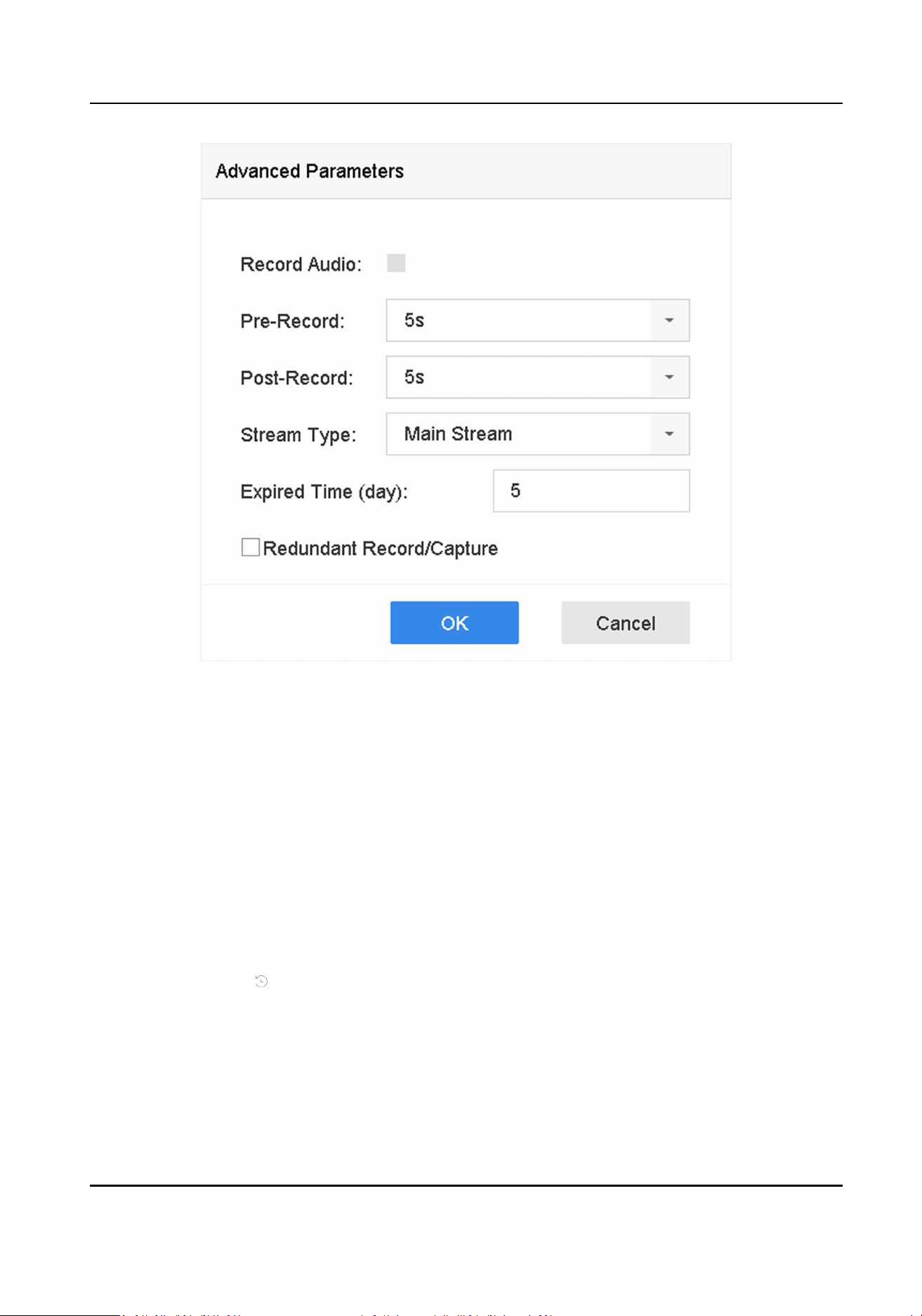
Figure 4-4 Record Parameters
6. Check Redundant Record/Capture.
7. Click OK to save sengs.
4.2 Playback
4.2.1 Instant Playback
Instant playback enables the device to play the recorded video les recorded in the last ve
minutes. If no video is found, it means there is no recording during the last ve minutes.
Aer selecng the camera on Live View, you can move the cursor to the window boom to access
the toolbar, and click to start instant playback.
Network Video Recorder User Manual
48
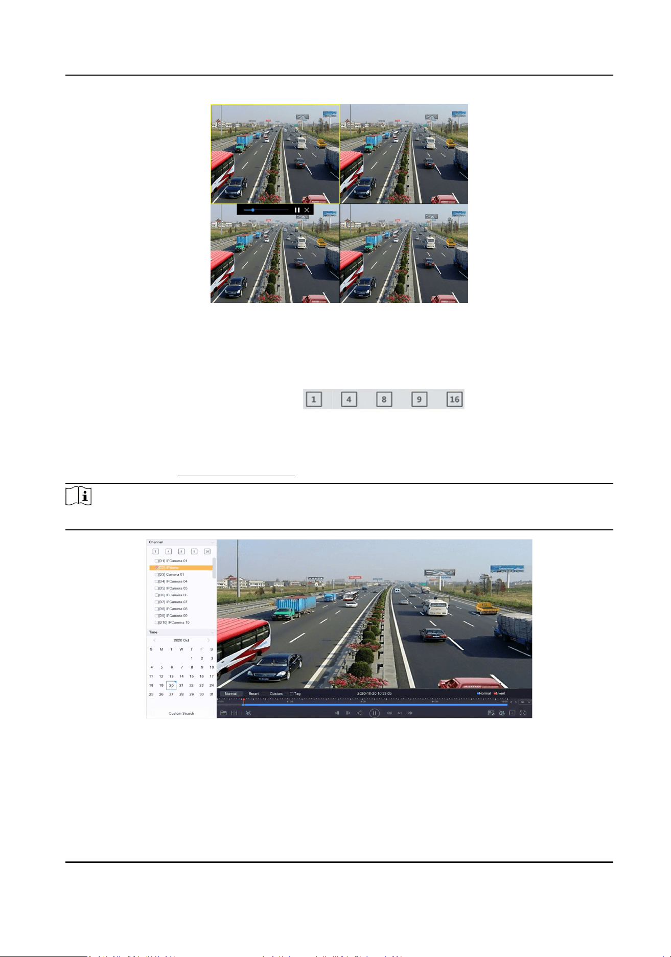
Figure 4-5 Playback
4.2.2 Play Normal Video
Go to Playback, select date and camera(s).
is the window division
shortcut for grouping cameras and playing videos. You can also select camera(s) from the list to
achieve simultaneous playback of mulple camera(s).
Posion the cursor on playback window, and use the toolbar at the boom to perform playback
operaons. Refer to Playback Operaons for details.
Note
256x playing speed is supported.
Figure 4-6 Play Normal Video
Network Video Recorder User Manual
49
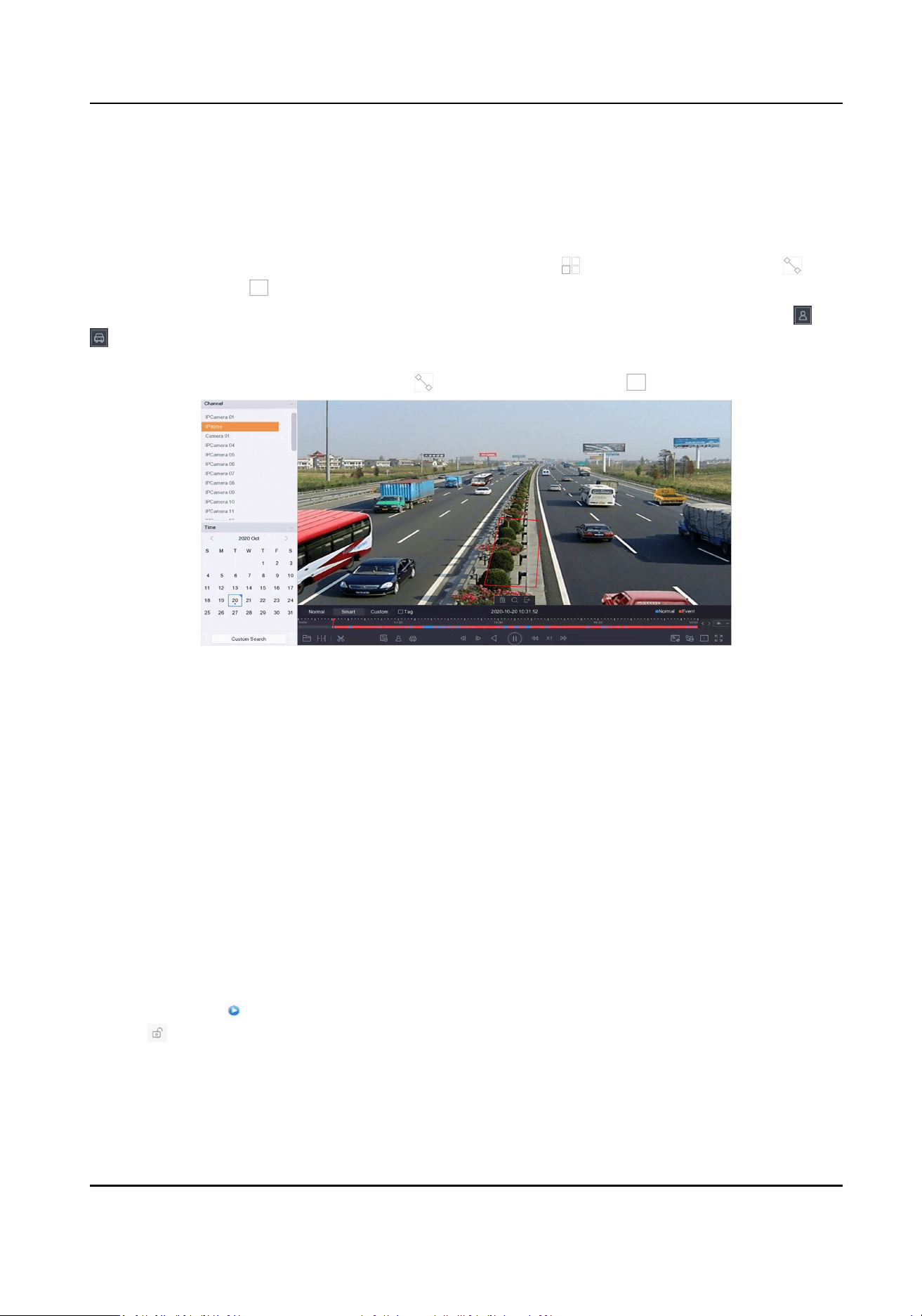
4.2.3 Play Smart Searched Video
In smart playback mode, the device can analyze videos that containing moon, line, or intrusion
detecon informaon, and mark them in red.
Go to Playback, click Smart, and then click moon detecon ( ), line crossing detecon ( ), or
intrusion detecon ( ) in the toolbar at the boom to play the video as your desire.
For certain cameras that have enabled human and vehicle of moon detecon, you can click or
to search human and vehicle targets. When you are playing back videos that contain human or
vehicle targets, the device cannot use the videos (that contain human or vehicle targets) to apply a
double analysis of line crossing detecon ( ) or intrusion detecon ( ).
Figure 4-7 Payback by Smart Search
4.2.4 Play Custom Searched Files
You can play video by customized search condions.
Steps
1. Go to Playback.
2. Select camera(s) from the list.
3. Click Custom Search at the lower-le corner.
4. Select a search method. For example, Search by Appearance.
5. Set search condions
6. Click Start Search. The search result list displays 1 channel.
7. Click Channel to select a channel as your desire. It will display search results for the selected
channel.
8. Oponal: Click
to play a video.
9. Click to lock a le. The locked le will not be overwrien.
10. Oponal: Export search results to a backup device.
1)Select le(s) in the search result list, or check Select All to select all les.
2)Click Export to export the selected le(s) to a backup device.
Network Video Recorder User Manual
50

Note
●
You can click to view export progress.
●
You can click to return to search interface.
4.2.5 Play Tag Files
Video tag allows you to record informaon, such as people and locaons of a certain me point,
during playback. You can use video tag(s) to search video les and posion me point.
Add Tag Files
Steps
1. Go to Playback.
2. Search and play back the video le(s).
3. Click to add the tag.
4. Edit the tag informaon.
5. Click OK.
Note
Max. 64 tags can be added to a single video le.
Play Tag Files
Steps
1. Go to Playback.
2. Click Custom Search at the lower-le corner.
3. Click Search by Tag.
4. Set search condions, including me and tag keyword.
5. Click Start Search. The search result list displays 1 channel.
6. Click Channel to select a channel as your desire. It will display search results for the selected
channel.
7. Click
to play a video.
8. Oponal: Export search results to a backup device.
1) Select le(s) in the search result list, or check Select All to select all les.
2) Click Export to export the selected le(s) to a backup device.
Note
●
You can click to view export progress.
●
You can click to return to search interface.
Network Video Recorder User Manual
51
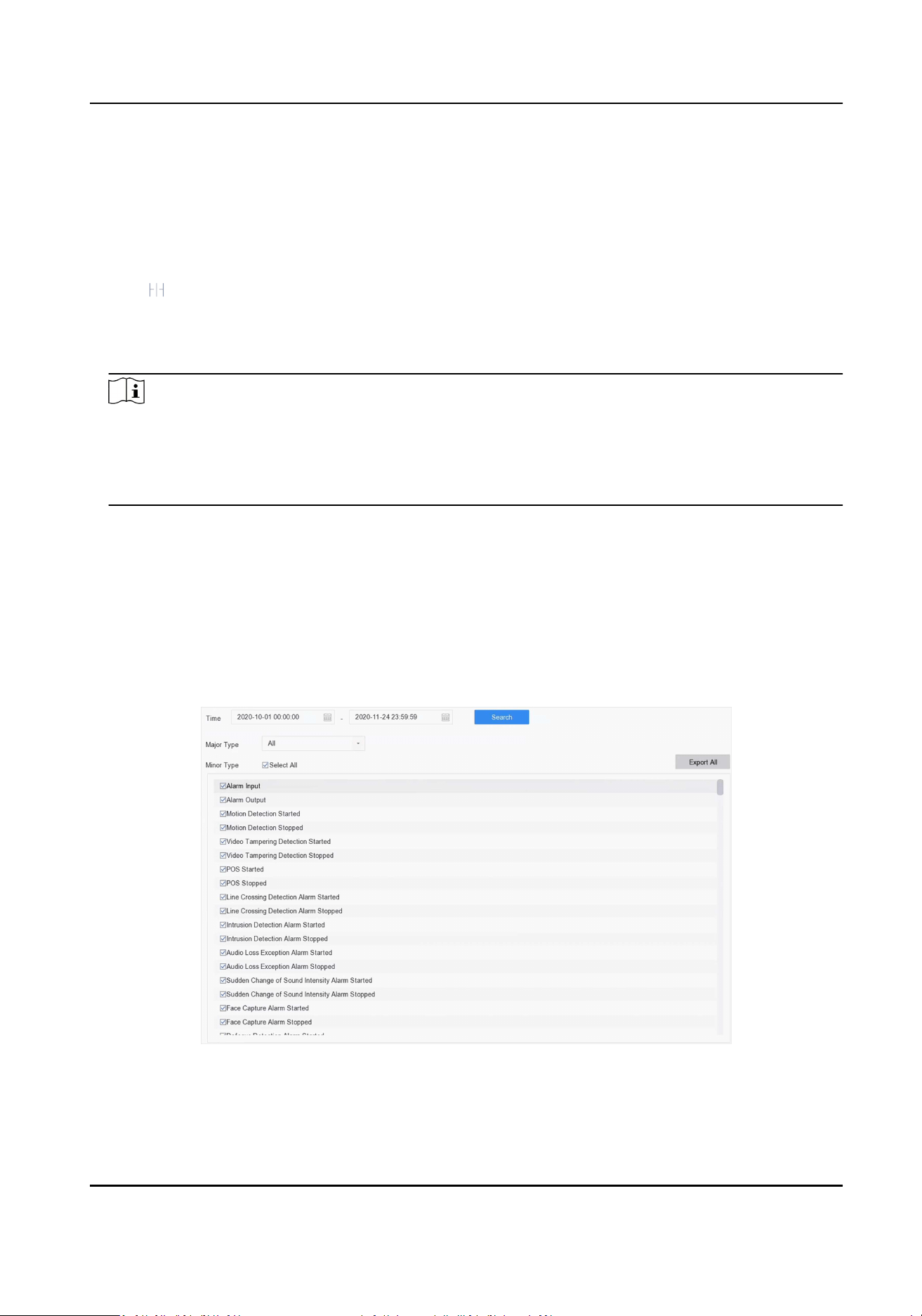
4.2.6 Play by Sub-periods
The video les can be played in mulple sub-periods simultaneously on the screen.
Steps
1. Go to Playback.
2. Click at the lower-le corner.
3. Select a camera.
4. Set the start me and end me for searching video.
5. Select the dierent mul-period at the lower-right corner, e.g., 4-Period.
Note
According to the dened number of split-screens, the video les on the selected date can be
divided into average segments for playback. E.g., if there are video les exisng between 16:00
and 22:00, and the 6-screen display mode is selected, then it can play the video les for 1 hour
on each screen simultaneously.
4.2.7 Play Log Files
Play back record le(s) associated with channels aer searching system logs.
Steps
1. Go to Maintenance → Log Info .
2. Click Log Search .
3. Set search me and type and click Search.
Figure 4-8 Search Log Files
4. Choose a log with a video le and click to start playing the log le.
Network Video Recorder User Manual
52

Figure 4-9 Play Log Files
4.2.8 Play External Files
You can play les from external storage devices.
Before You Start
Connect the storage device with the video les to your device.
Steps
1. Go to Playback.
2. Click at the lower-le corner.
3. Click , or double-click the le to play it.
4.3 Playback Operaons
4.3.1 View Playback Error Informaon
Playback error informaon of each channel can be accessed.
If excepon occurs, playback error informaon of individual channel(s) will be provided on the
screen. Go to Playback → Channel , select dierent channels to view if error informaon exists.
4.3.2 Set Play Strategy in Important/Custom Mode
When you are in the smart or custom video playback mode, you can set the playing speed
separately for the normal video and the smart/custom video, or you can select to skip the normal
video.
In the Smart/Custom video playback mode, click
to set the play strategy.
Network Video Recorder User Manual
53

●
When Do not Play Normal Videos is checked, the device will skip the normal video and play the
smart (moon/line crossing/intrusion) video and the custom (searched video) only in the normal
speed (X1).
●
When Do not Play Normal Videos is unchecked, you can set the play speed for the normal video
the smart/custom video separately. The speed range is from X1 to XMAX.
Note
You can set the speed in the single-channel play mode only.
4.3.3 Edit Video Clips
You can cut and export video clips during playback.
Steps
1. Go to Playback.
2. Click at the boom toolbar.
3. Set the start me and end me. You can click to set the me period, or set a me segment on
me bar.
4. Click to save the video clip to a storage device.
4.3.4 Switch between Main Stream and Sub-Stream
You can switch between the main stream and the sub-stream during the playback.
Icon Descripon
Play the video in main stream.
Play the video in sub-stream.
Note
The encoding parameters for the main stream and sub-stream can be congured in Storage →
Encoding Parameters .
4.3.5 Switch Audio Source
If the network has linked a network audio device, you can switch the audio source to the linked
audio device during playback.
Move the cursor to
at the toolbar, and then select an audio channel as your desire.
Network Video Recorder User Manual
54

4.3.6 Thumbnails View
With the thumbnails view on the playback interface, you can conveniently locate the required
video les on the me bar.
In the playback mode, posion the cursor on me bar to get preview thumbnails.
Figure 4-10 Thumbnails View
You can click a thumbnail to enter the full-screen playback.
4.3.7 Fisheye View
The device supports the sheye camera expansion in Live View or playback mode.
Before You Start
●
The sheye expansion view feature is supported only by certain models.
●
The connected camera must support the sheye view.
Steps
1. Start live view, click to enter the sheye expansion mode.
2. Select the expansion view mode.
Table 4-1 Fisheye View Icon Descripon
Icon Descripon Icon Descripon
180° Panorama ( ) Switch the Live View
image to the 180°
panorama view.
360° Panorama ( ) Switch the Live View
image to the 360°
panorama view.
PTZ Expansion ( ) The PTZ Expansion is
the close-up view of
some dened area in
the sheye view or
panorama expansion.
It supports the
electronic PTZ
funcon, also called e-
PTZ.
Radial Expansion ( ) In radial expansion
mode, the whole
wide-angle view of the
sheye camera is
displayed. This view
mode is called Fisheye
View because it
approximates the
vision of a sh’s
Network Video Recorder User Manual
55

Icon Descripon Icon Descripon
convex eye. The lens
produces curvilinear
images of a large area,
while distorng the
perspecve and
angles of objects in
the image.
4.3.8 Fast View
Hold the mouse to drag on the me bar to get a fast view of the video les.
In the Video Playback mode, hold and drag the mouse through the playing me bar to fast view
the video les.
Release the mouse at the required me point to enter the full-screen playback.
4.3.9 Digital Zoom
Digital Zoom zooms into the live image in dierent magnicaons (1x to 16x).
Steps
1. Start live view.
2. Click from the toolbar.
3. Move the sliding bar or scroll the mouse wheel to zoom in/out the image to dierent
magnicaons (1x to 16x).
Network Video Recorder User Manual
56
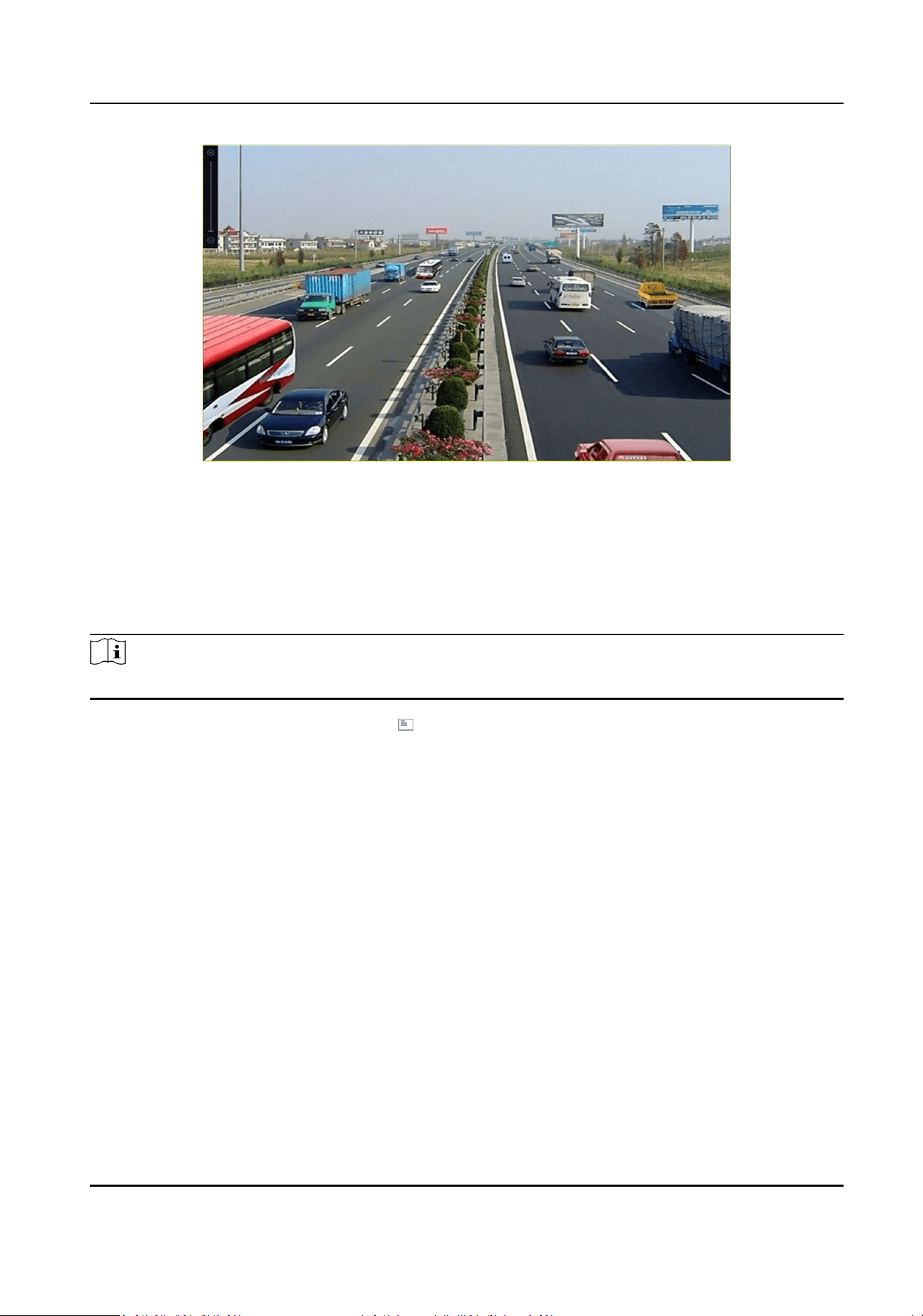
Figure 4-11 Digital Zoom
4.3.10 POS Informaon Overlay
The device can be connected with the POS machine/server, and receive the transacon message
for overlay on the image during playback.
Note
When the playing speed is higher than 2x, the POS informaon cannot be overlaid on the video.
In the video live or playback mode, click to overlay the POS transacon informaon on the
playback video.
Network Video Recorder User Manual
57

Chapter 5 Picture Capture
Note
This chapter is only available for certain models.
5.1 Congure Parameters
The picture refers to the live picture captured in connuous or event recording.
You can edit picture parameters in Storage → Schedule → Capture → Advanced .
Resoluon
Set the picture resoluon.
Picture Quality
Set picture quality to low, medium or high. Higher quality requires more storage space.
Interval
The live picture capture interval.
Capture Delay Time
The duraon of capturing pictures.
5.2 Congure Capture Schedule
The device will automacally capture picture according to the schedule.
Before You Start
Ensure you have installed HDDs, or added network disks for storage.
Steps
1. Go to Storage → Schedule → Capture .
2. Select a camera.
3. Set the picture capture schedule. Refer to Congure Recording Schedule for schedule seng
details.
5.3 Congure Holiday Capture Schedule
You can set the capture schedule on holidays of the year. The recorder will follow holiday capture
plan as its capture priority during holidays.
Before You Start
Ensure you have installed HDDs, or added network disks for storage.
Network Video Recorder User Manual
58
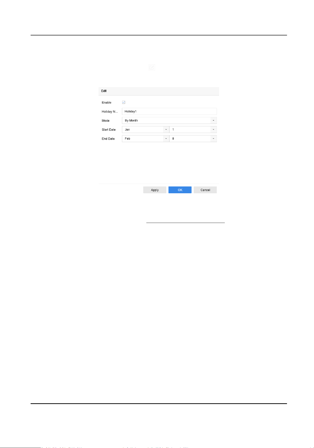
Steps
1. Go to System → Holiday .
2. Select a holiday item from the list and click .
3. Check Enable.
4. Edit holiday parameters, including name, mode, and date.
Figure 5-1 Edit Holiday Sengs
5. Click OK.
6. Set the holiday capture schedule. Refer to Congure Recording Schedule for schedule seng
details.
Network Video Recorder User Manual
59

Chapter 6 Event
6.1 Normal Event Alarm
6.1.1 Congure Moon Detecon Alarms
Moon detecon enables the device to detect the moving objects in the monitored area and
trigger alarms.
Steps
1. Go to System → Event → Normal Event → Moon Detecon .
2. Select a camera.
3. Check Enable.
4. Set the moon detecon rule.
For cameras have human
and vehicle detecon
funcon.
Click Draw Area to draw the detecon area(s) on the preview
screen.
Set Detecon Target as Human or Vehicle to discard alarms
which are not triggered by human body or vehicle.
For cameras do not have
human and vehicle
detecon funcon.
Click Full screen to set the full-screen as the detecon area, or
drag on the preview screen to draw the customized detecon
area.
5. Set Sensivity
Sensivity
Sensivity ranges from 0 to 100. It allows you to calibrate how readily movement triggers the
alarm. A higher value results in the more readily to triggers moon detecon.
6. Set the arming schedule. Refer to
Congure Arming Schedule .
7. Set linkage acons. Refer to Congure Linkage Acons .
6.1.2 Congure Video Loss Alarms
Video loss detecon detects video loss of a channel and takes alarm response acon(s).
Steps
1. Go to System → Event → Normal Event → Video Loss .
2. Select a camera.
3. Check Enable.
4. Set the arming schedule. Refer to
Congure Arming Schedule .
5. Set linkage acons. Refer to Congure Linkage Acons .
Network Video Recorder User Manual
60

6.1.3 Congure Video Tampering Alarms
Video tampering detecon triggered an alarm when the camera lens is covered and takes alarm
response acon(s).
Steps
1. Go to System → Event → Normal Event → Video Tampering .
2. Select a camera.
3. Check Enable.
4. Set the video tampering area. Drag on the preview screen to draw the customized video
tampering area.
5. Set Sensivity (0-2). 3 levels are available. The sensivity calibrates how readily movement
triggers the alarm. A higher value more readily triggers the video tampering detecon.
6. Set the arming schedule. Refer to Congure Arming Schedule .
7. Set linkage acons. Refer to Congure Linkage Acons .
6.1.4 Congure Sensor Alarms
Set the handling acon of an external sensor alarm.
Steps
1. Go to System → Event → Normal Event → Alarm Input .
2. Select an alarm input item from the list and click .
3. Select the alarm input type.
4. Edit the alarm name.
5. Check Input.
6. Set the arming schedule. Refer to Congure Arming Schedule .
7. Set linkage acons. Refer to Congure Linkage Acons .
6.1.5 Congure Excepons Alarms
Excepon events can be congured to take the event hint in the Live View window and trigger
alarm output and linkage acons.
Steps
1. Go to System → Event → Normal Event → Excepon .
2. Oponal: Enable the event hint to display it in the live view window.
1) Check Enable Event Hint.
2) Click
to select the excepon type(s) to take the event hint.
Network Video Recorder User Manual
61
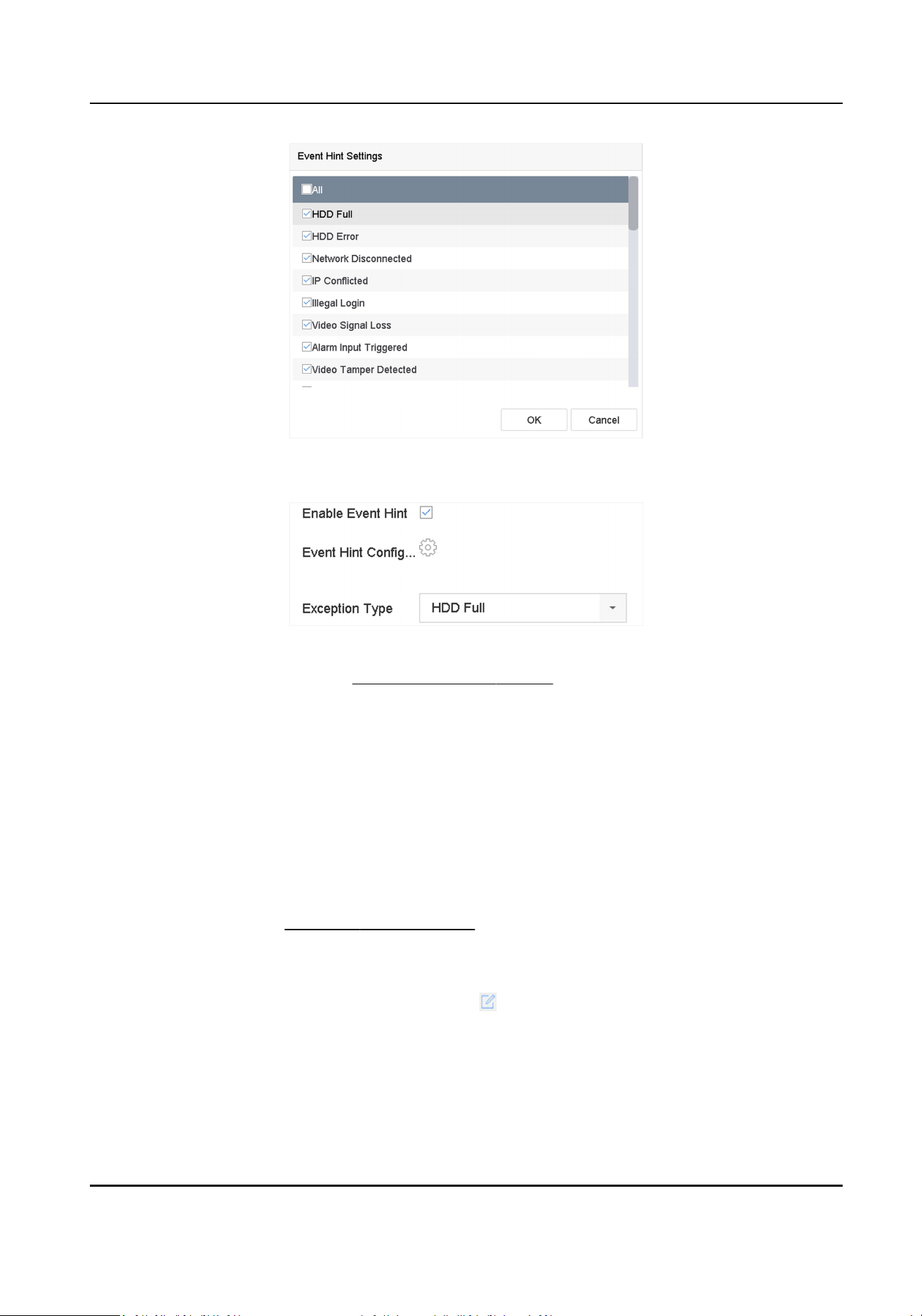
Figure 6-1 Event Hint Sengs
3. Select an excepon type.
Figure 6-2 Excepons Handling
4. Set the linkage acons. Refer to Congure Linkage Acons .
6.1.6 Congure Combined Alarm
Combined alarm combines events with alarm input. The combined alarm will be triggered when it
receives alarms from both alarm input and events. Event types include moon detecon, video
tampering detecon, and other smart events such as line crossing detecon, intrusion detecon,
etc.
Before You Start
Ensure the channel has been assigned with event alarm as your desire, and the alarm input has
been congured (refer to
Congure Sensor Alarms ).
Steps
1. Go to System → Event → Normal Event → Alarm Input .
2. Select an alarm input item from the list and click .
3. Select Sengs as Input.
4. Click Combined Alarm.
5. Select a channel as your desire.
6. Select Combined Alarm Event.
7. Click Apply.
Network Video Recorder User Manual
62
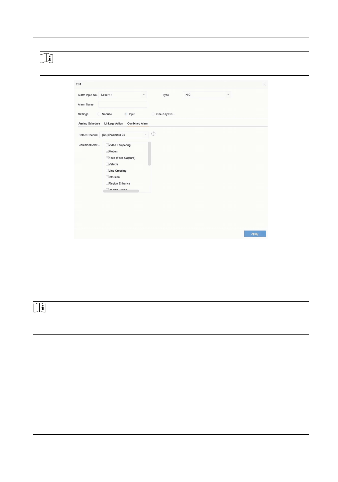
Note
The combined alarm arming schedule and linkage acon are the same as the selected event(s).
Figure 6-3 Combined Alarm
6.2 VCA Event Alarm
The device supports receiving VCA detecons sent by connected IP cameras. Enable and congure
VCA detecon on the IP camera sengs interface rst.
Note
●
VCA detecons must be supported by the connected IP camera.
●
Refer to the network camera user manual for detailed VCA detecon instrucons.
6.2.1 Temperature Screening
Aer specied thermography cameras are connected, the device can display temperature
measurement results, and nofy you with audio alert when normal or abnormal temperature is
detected.
Before You Start
Ensure your thermography camera supports this funcon, and it is properly congured.
Network Video Recorder User Manual
63

Steps
1. Go to System → Event → Smart Event .
2. Select the opcal channel of thermography camera.
3. Click Face Capture.
4. Oponal: Check Save VCA Picture to save the captured pictures of face detecon.
5. Set the arming schedule. Refer to Congure Arming Schedule .
6. Set linkage acons. Refer to Congure Linkage Acons . If you require to implement linkage
acons only when the thermography camera detects abnormal temperature, check Abnormal
Body Temperature in Rule Sengs.
Note
The abnormal temperature is detected and dened by the thermography camera.
7. Click Apply.
What to do next
●
You can check of Target in live view to view detecon results.
●
You can go to File Management → Smart Search → Search by Appearance to search detecon
results.
6.2.2 Transparent Transmission
Transparent transmission makes a large variety of events congurable, and the event alarms from
cameras can be directly transmied. For events which are not listed in smart event, they will be
listed in the transparent transmission list. The list will only display events which the connected
cameras support. You can custom the event descripon as your desire. Transparent transmission is
congurable via web browser.
Before You Start
Ensure you have correctly connected camera(s) that supports transparent transmission.
Steps
1. Go to Conguraon → Event → More Events → Transparent Transmission Conguraon . The
available events are listed in Event Descripon List.
2. Click Template List to export the template list le.
Note
The template list is for reference only. It cannot be deleted or edited.
3. Edit Event Descripon according to your camera and the template list.
Event Type
The event type shall be the same as your camera event.
Event Descripon
The event descripon can be customized. Aer the event type is recognized, the device will
display the event descripon as the event name.
Network Video Recorder User Manual
64
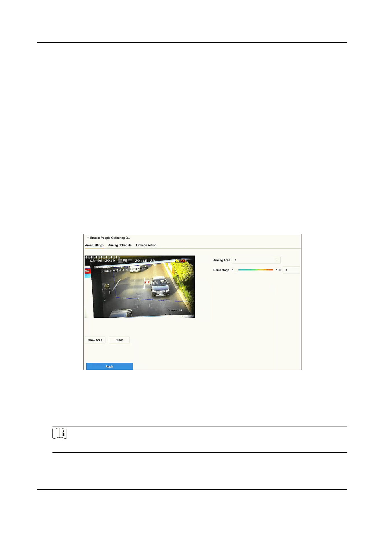
4. Click Save.
What to do next
Go to Conguraon → Event → Smart Event → More Events to congure events.
6.2.3 Hard Hat Detecon
Hard hat detecon detects people who are not wearing hard hats. You can congure the arming
schedule and linkage acons. Hard hat detecon is congurable via web browser.
6.2.4 People Gathering Detecon
People gathering detecon is used to detect whether the density of human bodies within a
specied area exceeds the set value and trigger alarm for linked acons.
Steps
1. Go to Smart Analysis → Smart Event Sengs → Other Events .
2. Select a camera.
3. Click People Gathering.
Figure 6-4 People Gathering Detecon
4. Check Enable People Gathering Detecon.
5. Oponal: Check Save VCA Picture to save the captured people gathering detecon pictures.
6. Set people gathering detecon parameters.
1) Select Arming Area.
Note
Up to 4 areas are selectable.
Network Video Recorder User Manual
65
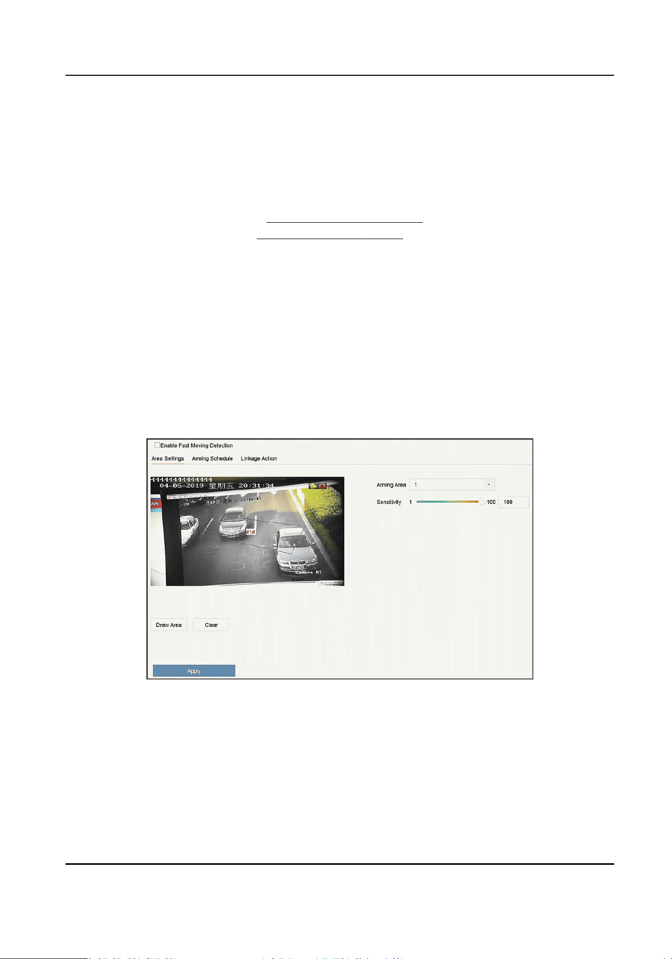
2) Click Draw Area to draw a quadrilateral in the preview window by specifying four verces of
the area.
3) Set Percentage.
Percentage
The density of human bodies within the area. If it exceeds the threshold value, the device
will trigger alarm.
7. Set the arming schedule. Refer to Congure Arming Schedule .
8. Set the linkage acons. Refer to Congure Linkage Acons .
9. Click Apply.
6.2.5 Fast Moving Detecon
Fast moving detecon is used to detect suspicious running and chasing, over-speed, and fast
moving. It will trigger alarm when an object is moving fast and send nocaon to arming host so
that necessary acons can be taken in advance.
Steps
1. Go to Smart Analysis → Smart Event Sengs → Other Events .
2. Select a camera.
3. Click Fast Moving.
Figure 6-5 Fast Moving Detecon
4. Check Enable Fast Moving.
5. Oponal: Check Save VCA Picture to save the captured fast moving detecon pictures.
6. Set fast moving detecon parameters.
1) Select Arming Region. Up to 4 regions are selectable.
2) Click Draw Area to draw a quadrilateral in the preview window by specifying four verces of
the area.
Network Video Recorder User Manual
66
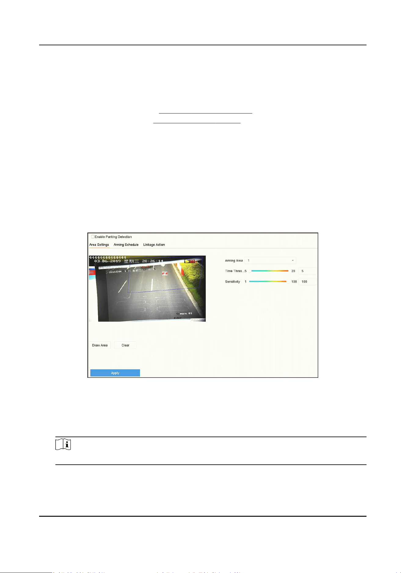
3) Set Sensivity.
Sensivity
Similarity of the background image to the object. The higher the value is, more easily the
detecon alarm will be triggered.
7. Set the arming schedule. Refer to Congure Arming Schedule .
8. Set the linkage acons. Refer to Congure Linkage Acons .
9. Click Apply.
6.2.6 Parking Detecon
Parking detecon is used to detect parking violaon in the area, applicable in expressway and one-
way street.
Steps
1. Go to Smart Analysis → Smart Event Sengs → Other Events .
2. Select a camera.
3. Click Parking.
Figure 6-6 Parking Detecon
4. Check Enable Parking Detecon.
5. Oponal: Check Save VCA Picture to save the captured parking detecon pictures.
6. Set parking detecon parameters.
1) Select Arming Area.
Note
Up to 4 areas are selectable.
2) Set Time Threshold.
Time Threshold
Network Video Recorder User Manual
67
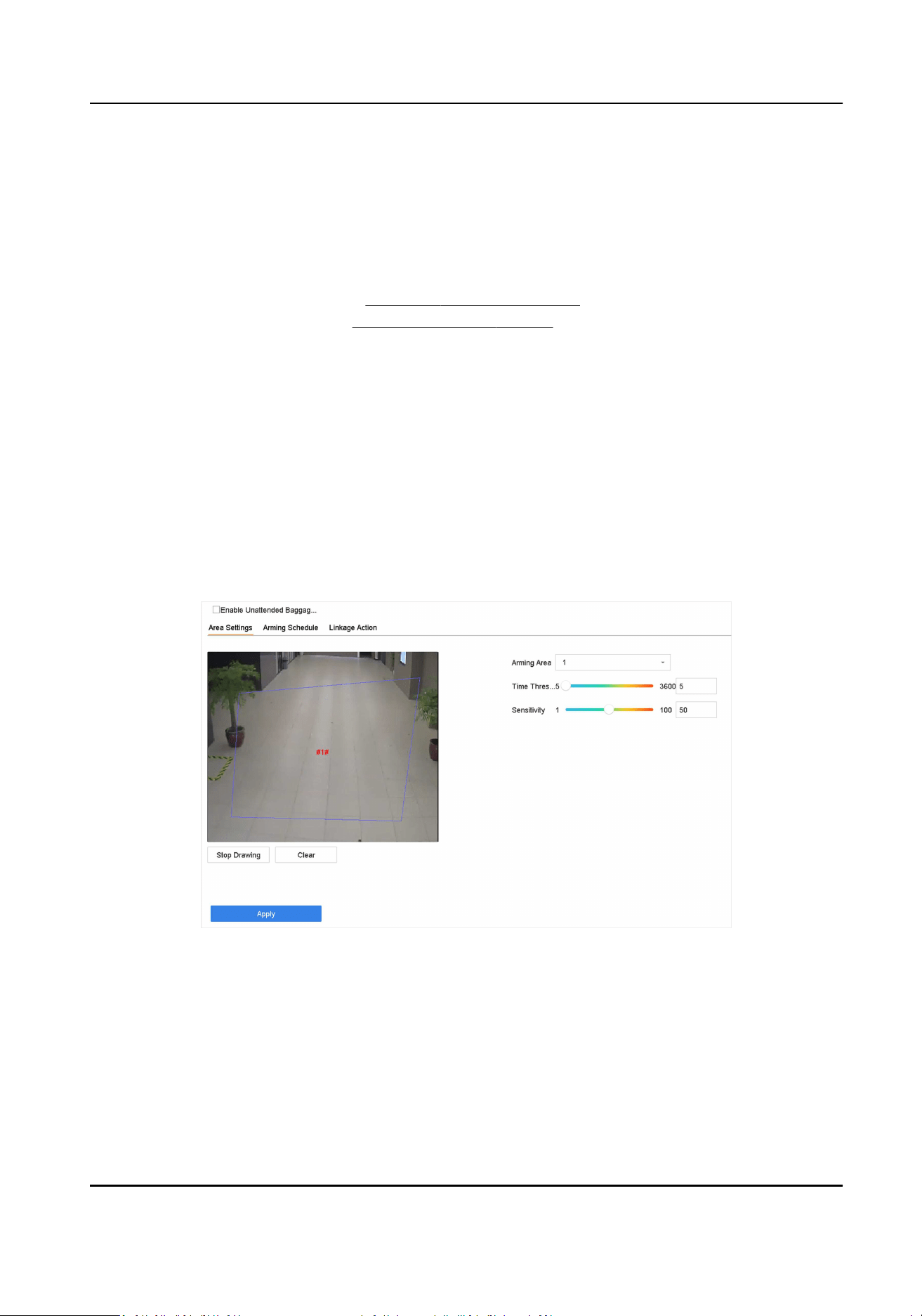
The me of a vehicle staying in the region. If the value is 10, an alarm will be triggered aer
the vehicle has stayed in the region for 10 s. Range: [5-20].
3) Set Sensivity.
Sensivity
Similarity of the background image to the object. The higher the value is, more easily the
detecon alarm will be triggered.
7. Set the arming schedule. Refer to Congure Arming Schedule .
8. Set the linkage acons. Refer to Congure Linkage Acons .
9. Click Apply.
6.2.7 Unaended Baggage Detecon
Unaended baggage detecon detects the objects le over in a predened region such as the
baggage, purses, dangerous materials, etc., and a series of acons can be taken when the alarm is
triggered.
Steps
1. Go to Smart Analysis → Smart Event Sengs → Other Events .
2. Select a camera.
3. Click Unaended Baggage.
Figure 6-7 Unaended Baggage Detecon
4. Check Enable Unaended Baggage Detecon.
5. Oponal: Check Save VCA Picture to save the captured unaended baggage detecon pictures.
6. Set the detecon rules and detecon areas.
1) Select Arming Area.
Network Video Recorder User Manual
68
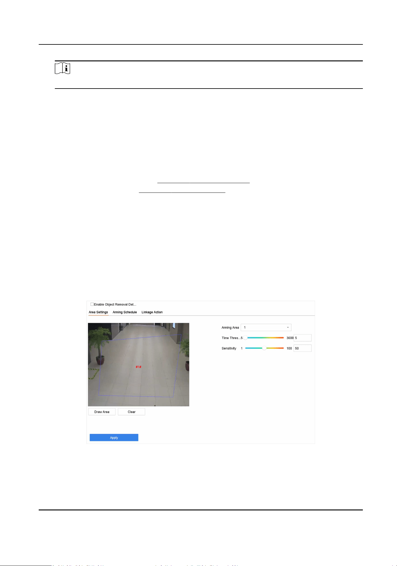
Note
Up to 4 areas are selectable.
2) Drag the sliders to set Time Threshold and Sensivity.
Time Threshold
The me of the objects le in the region. If the value is 10, an alarm will be triggered aer
the object is le and stayed in the region for 10 s. Range: [5-20].
Sensivity
Similarity of the background image to the object. The higher the value is, more easily the
detecon alarm will be triggered.
3) Click Draw Region and draw a quadrilateral in the preview window.
7. Set the arming schedule. Refer to Congure Arming Schedule .
8. Set linkage acons. Refer to Congure Linkage Acons .
9. Click Apply.
6.2.8 Object Removal Detecon
The object removal detecon funcon detects the objects removed from a predened region, such
as the exhibits on display, and a series of acons can be taken when the alarm is triggered.
Steps
1. Go to Smart Analysis → Smart Event Sengs → Other Events .
2. Select a camera.
3. Click Object Removable.
Figure 6-8 Object Removal Detecon
4. Check Enable Object Removable Detecon.
5. Oponal: Check Save VCA Picture to save the captured object removable detecon pictures.
Network Video Recorder User Manual
69
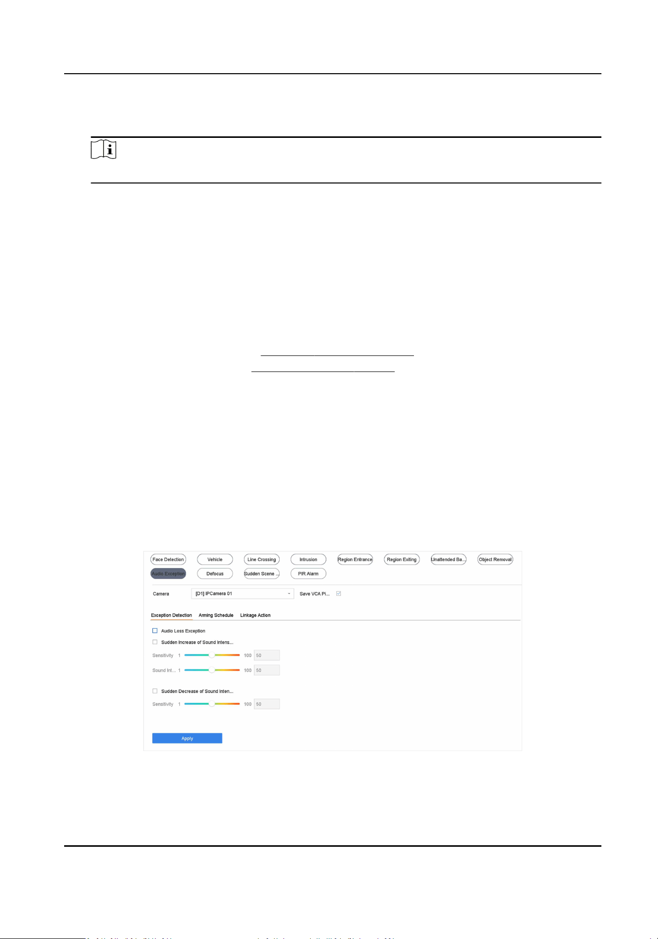
6. Follow these steps to set the detecon rules and detecon areas.
1) Select Arming Area.
Note
Up to 4 areas are selectable.
2) Drag the sliders to set Time Threshold and Sensivity.
Time Threshold
The me of the objects removed from the region. If the value is 10, alarm will be triggered
aer the object disappears from the region for 10 s. Range [5-20].
Sensivity
The similarity degree of the background image. If the sensivity is high, a very small object
taken from the region will trigger the alarm.
3) Click Draw Area and draw a quadrilateral in the preview window by specifying four verces of
the detecon region.
7. Set the arming schedule. Refer to Congure Arming Schedule .
8. Set the linkage acons. Refer to Congure Linkage Acons .
9. Click Apply.
6.2.9 Audio Excepon Detecon
Audio excepon detecon detects abnormal sounds in the scene, such as a sudden increase/
decrease in sound intensity.
Steps
1. Go to Smart Analysis → Smart Event Sengs → Other Events .
2. Select a camera.
3. Click Audio Excepon.
Figure 6-9 Audio Excepon Detecon
4. Oponal: Check Save VCA Picture to save the captured audio excepon detecon pictures.
Network Video Recorder User Manual
70

5. Set the detecon rules.
1) Select Excepon Detecon.
2) Check Audio Loss Excepon, Sudden Increase of Sound Intensity Detecon, and/or Sudden
Decrease of Sound Intensity Detecon.
Audio Loss Excepon
Detects a steep sound rise in the scene. Set Sensivity and Sound Intensity Threshold for
the steep sound rise.
Sensivity
The smaller the value is, the more severely the change would trigger the detecon. Range
[1-100].
Sound Intensity Threshold
It can lter the sound in the environment. The louder the environment sound is, the higher
the value should be. Adjust it according to the environment. Range [1-100].
Sudden Decrease of Sound Intensity Detecon
Detects a steep sound drop in the scene. Detecon sensivity [1-100].
6. Set the arming schedule. Refer to Congure Arming Schedule .
7. Set the linkage acons. Refer to Congure Linkage Acons .
8. Click Apply.
6.2.10 Defocus Detecon
Image blur caused by lens defocus can be detected.
Steps
1. Go to Smart Analysis → Smart Event Sengs → Other Events .
2. Select a camera.
3. Click Defocus.
Network Video Recorder User Manual
71

Figure 6-10 Defocus Detecon
4. Check Enable.
5. Oponal: Check Save VCA Picture to save the captured defocus detecon pictures.
6. Set the detecon sensivity.
Sensivity
Sensivity range: [1-100]. The higher the value is, the more easily the defocus image will be
detected.
7. Set the arming schedule. Refer to Congure Arming Schedule .
8. Set the linkage acons. Refer to Congure Linkage Acons .
9. Click Apply.
6.2.11 Sudden Scene Change Detecon
Scene change detecon detects the change of the video security environment aected by external
factors, such as the intenonal rotaon of the camera.
Steps
1. Go to Smart Analysis → Smart Event Sengs → Other Events .
2. Select a camera.
3. Click Sudden Scene Change.
Network Video Recorder User Manual
72

Figure 6-11 Sudden Scene Change
4. Check Enable.
5. Oponal: Check Save VCA Picture to save the captured sudden scene change detecon pictures.
6. Set the detecon sensivity.
Sensivity
Ranges from 1 to 100, the higher the value, the more easily the change of scene can trigger
the alarm.
7. Set the arming schedule. Refer to Congure Arming Schedule .
8. Set the linkage acons. Refer to Congure Linkage Acons .
9. Click Apply.
6.2.12 PIR Alarm
A PIR (Passive Infrared) alarm is triggered when an intruder moves within the detector vision eld.
The heat energy dissipated by a person or any other warm blooded creature such as dogs, cats,
etc., can be detected.
Steps
1. Go to Smart Analysis → Smart Event Sengs → Other Events .
2. Select a camera.
3. Click PIR Alarm.
Network Video Recorder User Manual
73

Figure 6-12 PIR Alarm
4. Check PIR Alarm.
5. Oponal: Check Save VCA Picture to save the captured of PIR alarm pictures.
6. Set the arming schedule. Refer to Congure Arming Schedule .
7. Set the linkage acons. Refer to Congure Linkage Acons .
8. Click Apply.
6.2.13 Thermal Camera Detecon
The NVR supports the event detecon modes of the thermal network cameras: re and smoke
detecon, temperature detecon, temperature dierence detecon, etc.
Before You Start
Add the thermal network camera to your device and make sure the camera is acvated.
Steps
1. Go to Smart Analysis → Smart Event Sengs → Other Events .
2. Select a thermal camera.
3. Oponal: Check Save VCA Picture to save the captured pictures of detecon.
4. Select an event detecon (Temperature Measurement Alarm, etc.).
5. Set the arming schedule. Refer to
Congure Arming Schedule .
6. Set the linkage acons. Refer to Congure Linkage Acons .
7. Click Apply.
Network Video Recorder User Manual
74

6.2.14 Queue Management
Aer connecng with queue management camera, you can set the arming schedule and linkage
acon of queue management.
Before You Start
Ensure the recorder have connected with queue management camera.
Steps
1. Go to Smart Analysis → Smart Event Sengs → Other Events .
2. Select a queue management camera.
3. Oponal: Check Save VCA Picture to save the captured pictures of detecon.
4. Set the arming schedule. Refer to Chapter Congure Arming Schedule for details.
5. Set the linkage acons. Refer to Chapter Congure Linkage Acons for details.
6. Click Apply.
6.3 Congure Arming Schedule
Steps
1. Click Arming Schedule.
2. Click Edit.
3. Select a day of the week and set the me period. Up to eight me periods can be set each day.
Note
Time periods cannot repeat or overlapped.
Network Video Recorder User Manual
75
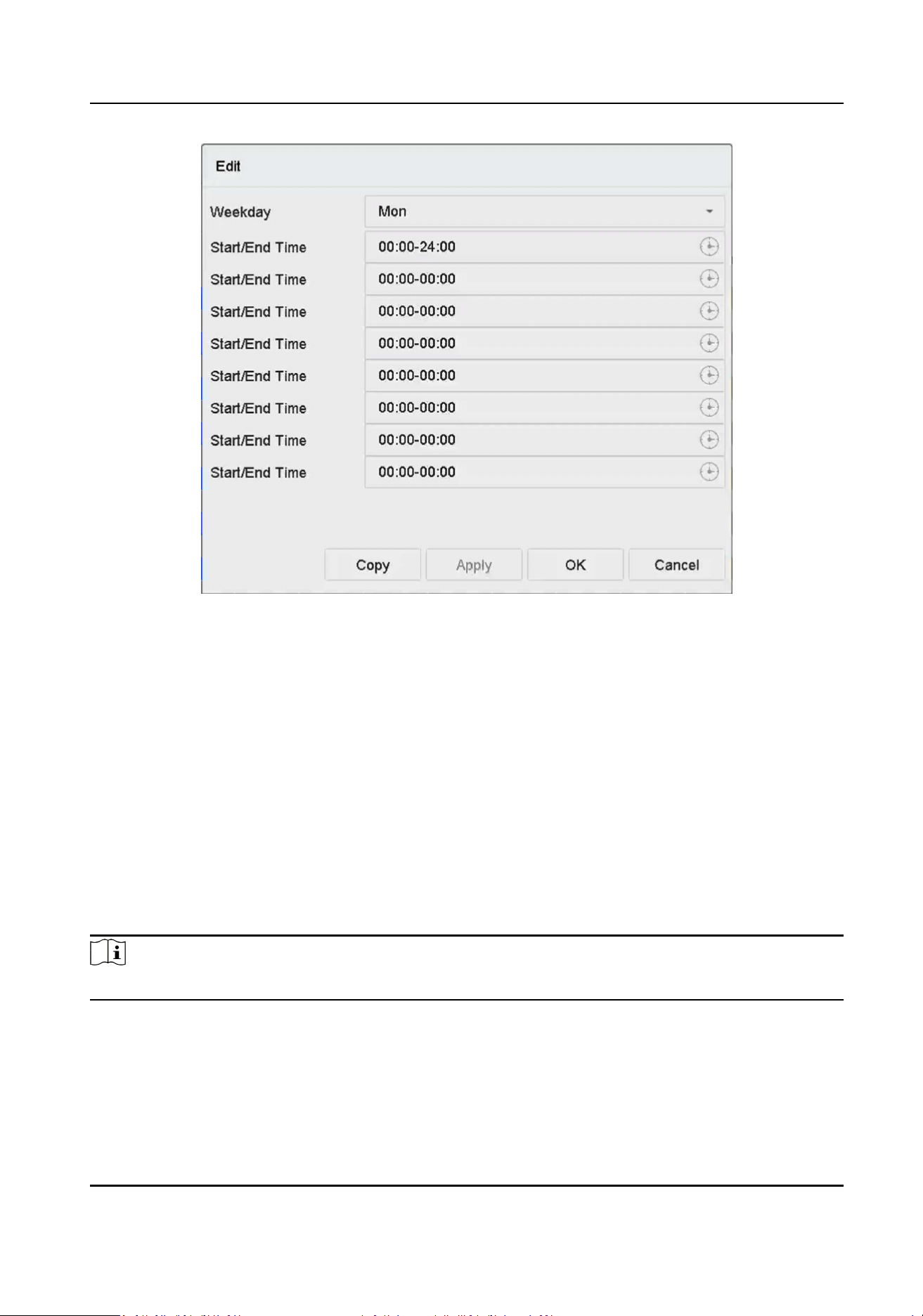
Figure 6-13 Set Arming Schedule
4. You can click Copy to copy the current day arming schedule sengs to other day(s).
5. Click Apply to save the sengs.
6.4 Congure Linkage Acons
Alarm linkage acons will be acvated when an alarm or excepon occurs.
6.4.1 Congure Auto-Switch Full Screen Monitoring
When an alarm is triggered, the local monitor displays in full screen the video image from the
alarming channel congured for full screen monitoring. And when the alarm is triggered
simultaneously in several channels, you must congure the auto-switch dwell me.
Note
Auto-switch will terminate once the alarm stops and back to the live view interface.
Steps
1. Go to System → Live View → General .
2. Set the event output and dwell me.
Event Output
Network Video Recorder User Manual
76

Select the output to show the event video.
Full Screen Monitoring Dwell Time
Set the me in seconds to show the alarm event screen. If alarms are triggered
simultaneously in several channels, their full-screen images will be switched at an interval of
10 seconds (default dwell me).
3. Go to the Linkage Acon interface of the alarm detecon (e.g., moon detecon, video
tampering, face detecon, etc.).
4. Select the Full Screen Monitoring alarm linkage acon.
5. Select the channel(s) in Trigger Channel for full screen monitoring.
6.4.2 Congure Buzzer
When an alarm is detected, the buzzer will make an audible beep.
Steps
1. Go to System → Live View → General .
2. Check Enable Audio Output.
3. Set the audio volume.
4. Click Apply.
5. Go to Linkage Acon interface of the alarm detecon (e.g., moon detecon, video tampering,
face detecon, etc.).
6. Select Buzzer as the alarm linkage acon.
6.4.3 Nofy Surveillance Center
The device can send an excepon or alarm signal to the remote alarm host when an event occurs.
The alarm host refers to the PC installed with client soware (e.g., iVMS-4200, iVMS-5200).
Steps
1. Go to System → Network → Advanced → More Sengs .
2. Set the alarm host IP and alarm host port.
3. Go to Linkage Acon interface of the alarm detecon (e.g., moon detecon, video tampering,
face detecon, etc.).
4. Select Nofy Surveillance Center.
6.4.4 Congure Email Linkage
The system can send an email with alarm informaon to a user or users when an alarm is detected.
Steps
1. Go to System → Network → Advanced → Email .
2. Set the email parameters.
3. Click Apply.
Network Video Recorder User Manual
77

4. Go to the Linkage Acon interface of the alarm detecon (e.g., moon detecon, video
tampering, face detecon, etc.).
5. Select Send Email alarm linkage acon.
6.4.5 Congure Audio Alert
When an alarm is triggered, an audio le will be played as the linkage acon. The audio le can be
customized. Refer to Audio Management for details.
Before You Start
Ensure the audio les are imported to the device.
Steps
Note
This linkage acon is only available for certain events.
1. Check Audio Alert in Normal Linkage.
2. Click to select audio le.
3. Select an audio le.
4. Set arming schedule.
5. Click OK.
6. Click Apply.
6.4.6 Trigger Alarm Output
The alarm output can be triggered by the alarm input, moon detecon, video tampering
detecon, face detecon, line crossing detecon, and any all other events.
Steps
1. Go to Linkage Acon of the alarm detecon (e.g., moon detecon, face detecon, line crossing
detecon, intrusion detecon, etc.).
2. In Trigger Alarm Outputs, select the alarm output(s) to trigger.
3. Go to System → Event → Normal Event → Alarm Output .
4. Select an alarm output item from the list.
6.4.7 Congure Audio and Light Alarm Linkage
For certain network cameras, you can set the alarm linkage acon as audio alarm or light alarm.
Before You Start
●
Ensure your camera supports audio and light alarm linkage.
●
Ensure the audio output and volume are properly congured.
Network Video Recorder User Manual
78

Steps
1. Go to the linkage acon interface of the alarm detecon (e.g., moon detecon).
2. Set Audio and Light Alarm Linkage as your desire.
3. Click Apply.
6.4.8 Congure PTZ Linkage
The system can trigger the PTZ acons (e.g., call preset/patrol/paern) when the alarm event, or
VCA detecon events occurs.
Before You Start
Make sure the connected PTZ or speed dome connected supports PTZ linkage.
Steps
1. Go to Linkage Acon interface of the alarm input or VCA detecon (e.g., face detecon, line
crossing detecon, intrusion detecon, etc.).
2. Select the PTZ Linkage.
3. Select the camera to perform the PTZ acons.
4. Select the preset/patrol/paern No. to call when the alarm events occur.
Note
You can set only one PTZ type for the linkage acon each me.
Network Video Recorder User Manual
79
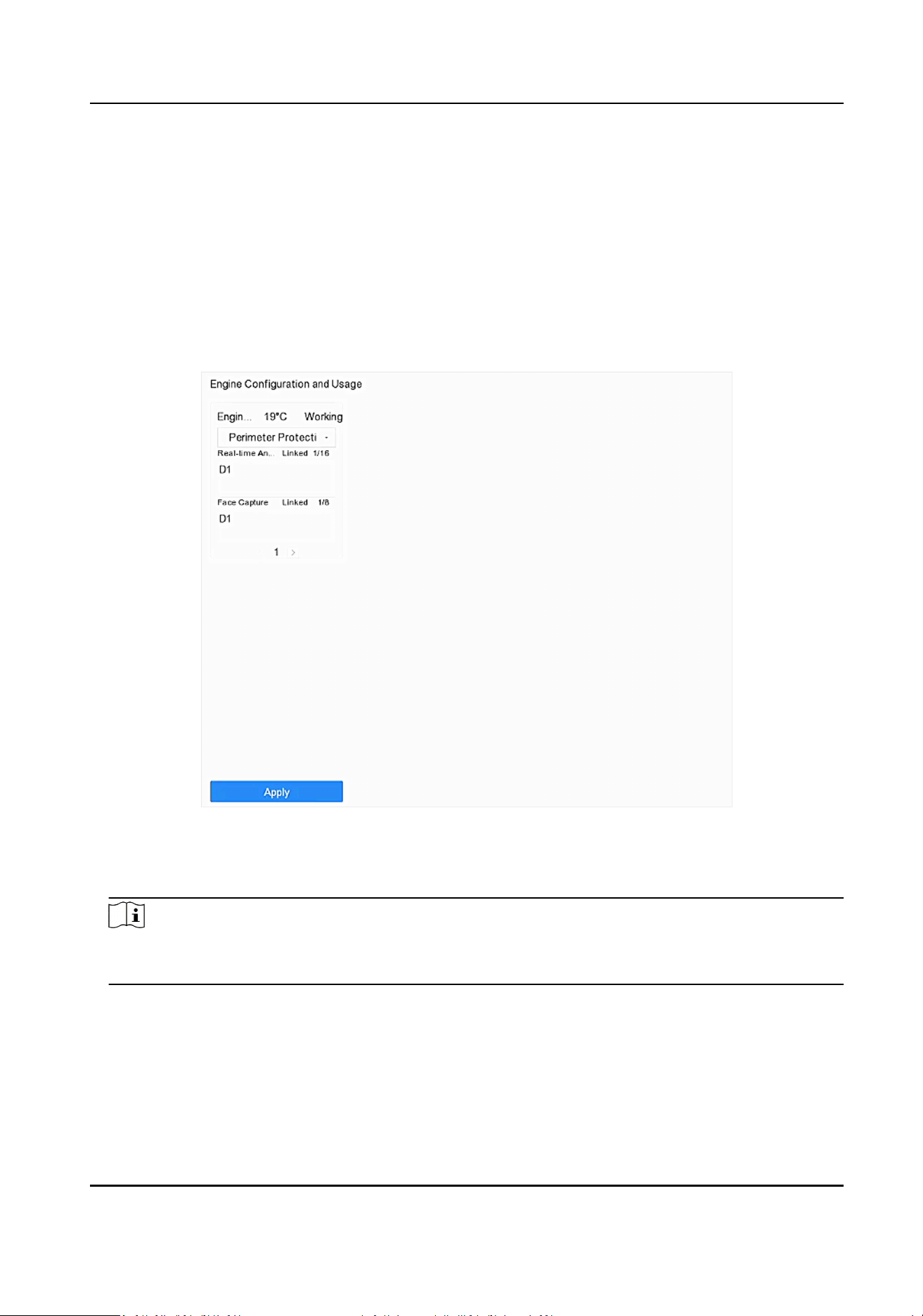
Chapter 7 Smart Analysis
7.1 Engine Conguraon
Each engine processes a specied VCA type as its working mode. You can congure the engine
working mode as your desire.
Steps
1. Go to Smart Analysis → Engine Sengs → Engine Conguraon .
Figure 7-1 Engine Conguraon
2. Congure each engine usage. You can view the engine temperature and linked channel status of
each funcon.
Note
If the engine has been bound with channel(s), switching engine working mode will unbind the
engine and channel(s), and cancel the related smart event of the channel.
3. Click Apply to save the sengs.
Network Video Recorder User Manual
80
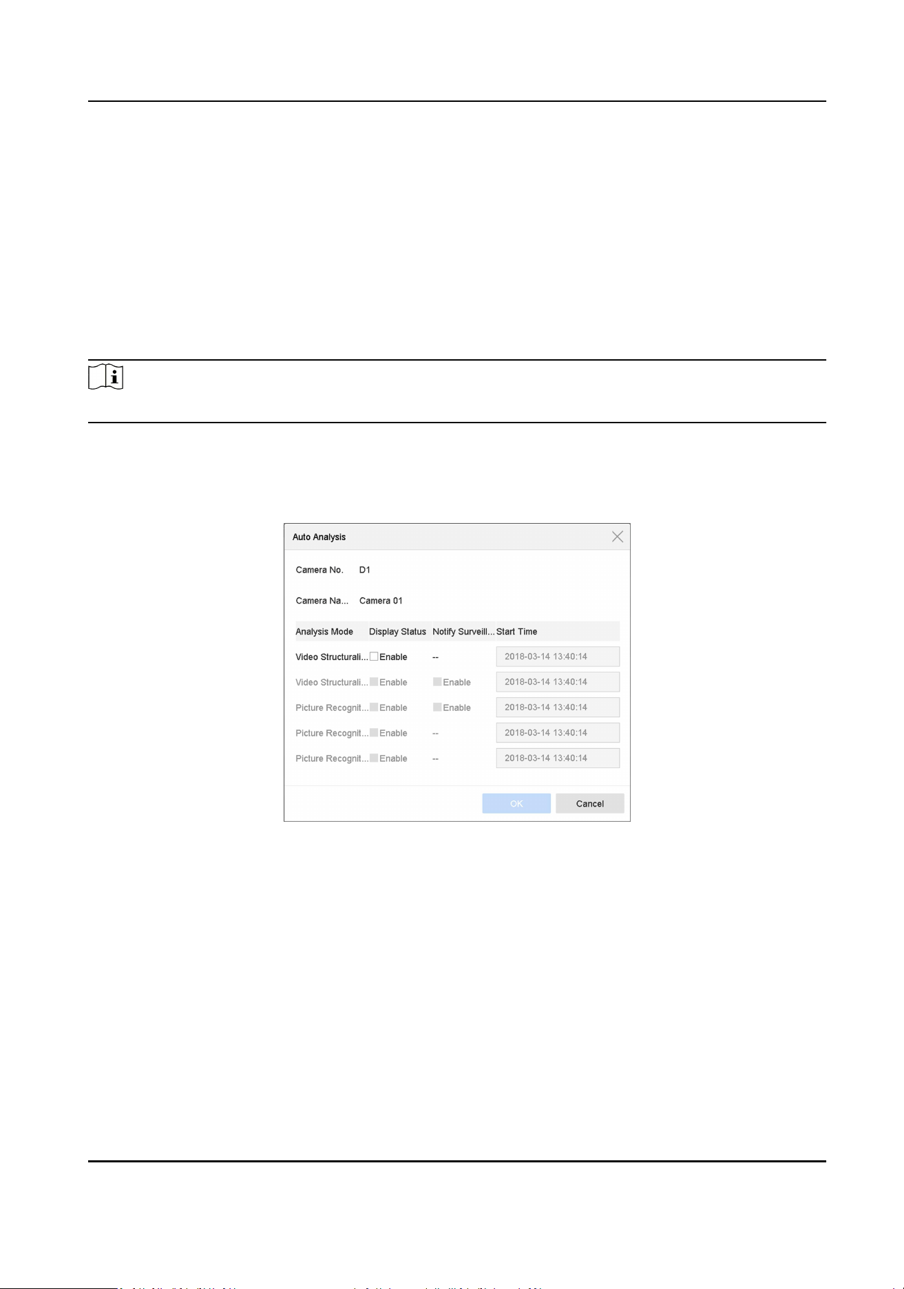
7.2 Task Conguraon
You can view the task status in task conguraon. Smart analysis results are used for ltering the
pictures when searching interested human body and vehicle pictures.
Before You Start
Check Save VCA Pictures for human body detecon/vehicle detecon, line crossing detecon,
intrusion detecon, region entrance, or region exing.
Steps
Note
The chapter is only available for certain models of iDS series.
1. Go to Smart Analysis → Engine Sengs → Task Conguraon .
2. Check cameras to enable corresponding analysis mode. Ensure engine is available for the
selected analysis mode.
3. Enable auto analysis.
Figure 7-2 Auto Analysis
1) Click Edit.
2) Oponal: Check Enable of Display Status and Nofy Surveillance Center.
3) Set Start Time of video to analyze.
4) Click OK.
4. Check cameras and click Enabled to start analyzing.
Task status includes 3 condions: Disabled, Waing, and Enabled.
Disabled
No analysis task is enabled on the camera.
Waing
Network Video Recorder User Manual
81

The analysis task of the camera is enabled. Device is waing to analyze data.
Enabled
The analysis task of the camera is enabled and device is analyzing data of the camera.
5. Oponal: For Non-Real-Time Face Picture Comparison analysis mode, click View Record to view
the progress of each day.
7.3 Self-Learning
This chapter is only available for certain models of perimeter protecon events.
7.3.1 Training Task
Training task is used to improve perimeter protecon alarm accuracy. Aer it is enabled, the device
would automacally collect training materials from perimeter protecon events. When there are
enough materials, the device would run a round of training and update the algorithm at the preset
me.
Go to Smart Analysis → Self-Learning → Training Task to enable the funcon under Training Task.
Figure 7-3 Training Task
Task Status
The task status for material collecon. The progress would reach 100% when enough training
materials are collected.
Force Training
This funcon is mainly used for technical supports, and you are not recommended to use it. If
the collected materials are not enough, this funcon can force the device to run a round of
training for the current collected materials.
Auto Update
Aer a round of training is completed, the device would automacally update the algorithm
according to the preset me.
Note
●
Training Task is enabled by default.
●
Enabling Training Task would occupy one engine, so the number of available channels for smart
analysis may decrease.
●
When the algorithm is upgrading, the number of false alarms may currently be increased.
Network Video Recorder User Manual
82
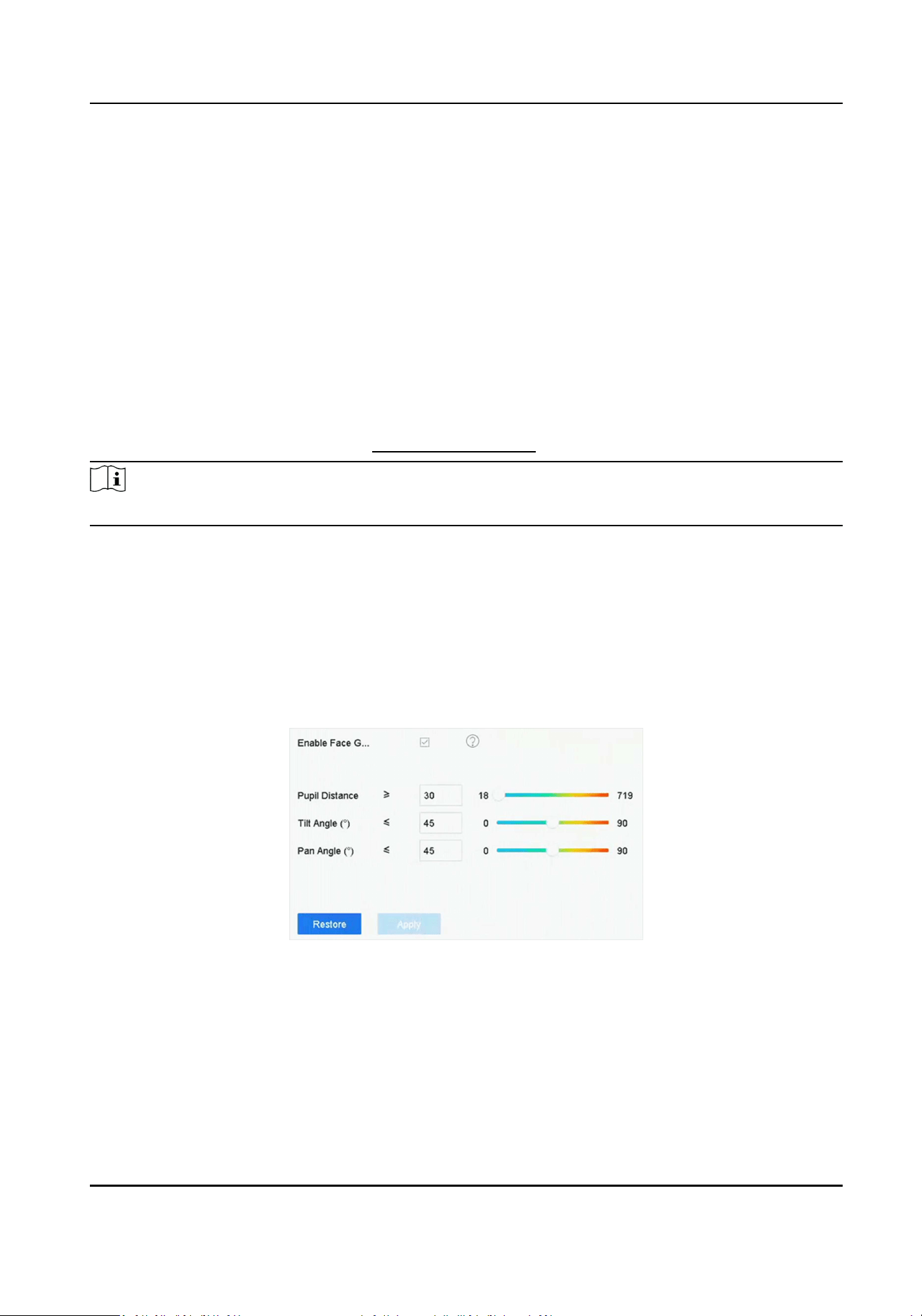
7.3.2 Algorithm Management
If the video scene is changed, or the alarm accuracy is not as good as it used to be, you can restore
it to previous version or the original version.
Go to Smart Analysis → Self-Learning → Algorithm Management to manage algorithm.
7.4 Face Picture Comparison
The device supports the face picture comparison alarm and face capture for the connected camera
based on face recognion feature.
Go to Smart Analysis → Engine Sengs → Engine Conguraon . Congure at least one engine
usage as Facial Recognion. Refer to Engine Conguraon for details.
Note
The chapter is only available for certain models.
7.4.1 Face Grading Conguraon
Face grading is used for face picture selecon. According to pupil distance, lt angle and pan angle,
it only uses face pictures which sasfy grading requirement for analysis. Larger pupil distance,
smaller lt and pan angle, beer it would be for analysis.
Steps
1. Go to Smart Analysis → Engine Sengs → Face Grading .
Figure 7-4 Face Grading
2. Check Enable Face Grading.
3. Set Pupil Distance, Tilt Angle, and Pan Angle.
Pupil Distance
Pupil distance is the distance between two pupils. In order to get beer detecon result, the
pupil distance shall not be less than 40, and the recommended value is 60.
Network Video Recorder User Manual
83

Tilt Angle
Tilt angle is the angle between your view and horizontal plane.
Pan Angle
Pan angle is the angle between your view and vercal plane.
4. Click Apply.
What to do next
●
Aer face picture modeling, you can view face grading score of each face picture via web
browser in Conguraon → Face Picture Library .
●
You can click in Smart Analysis → Face Picture Database to select face picture by face grading
score.
7.4.2 Face Capture
The face capture detects and captures faces appearing in the scene. Linkage acons can be
triggered when a human face is detected.
Steps
1. Go to Smart Analysis → Smart Event Sengs → Facial Recognion .
2. Click Face Capture.
Figure 7-5 Face Capture
3. Select a camera to congure.
4. Check Enable Face Capture.
5. Oponal: Check Save VCA Picture to save the captured pictures of face detecon.
6. Set the detecon sensivity.
Network Video Recorder User Manual
84

Note
Sensivity range: [1-5]. The higher the value is, the easier faces will be detected.
7. Set the arming schedule. Refer to Congure Arming Schedule .
8. Set linkage acons. Refer to Congure Linkage Acons .
9. Click Apply.
7.4.3 Face Picture Library Management
Face picture library is mainly used for face picture storage and face picture comparison.
Add a Face Picture Library
Steps
1. Go to Smart Analysis → Face Picture Database .
2. Click .
3. Enter the face picture library name.
4. Click OK.
Note
●
You can click or to edit the library name or delete the library.
●
You can click Delete in Batch or Clear in Batch to delete selected face picture libraries, or clear
all face pictures in the selected face picture libraries.
Upload Face Pictures to the Library
Face picture comparison is based on face pictures in the library. You can upload a single face
picture or import mulple face pictures to the library.
Before You Start
●
Ensure the picture format is JPEG or JPG.
●
Import all pictures to a backup device in advance.
Steps
1. Select a face picture library in the list.
2. Click Add or Import.
3. Import picture(s).
-
Add: Click Add to import a face picture.
Note
You can only upload one human face at a me. If the picture has mulple human faces, you
have to pick one from them.
Network Video Recorder User Manual
85

-
Import: Click Import to import mulple face pictures. The device will use the le name as its
face picture name and leave other aributes empty, or import picture les by specied rules.
If a picture le has mulple human faces, the device will choose the human face at the center
by default.
4. Oponal: Select pictures and click Copy to to copy the uploaded pictures of the current library
to other library.
5. Oponal: Select a picture and click Edit to modify the picture informaon.
6. Oponal: Select a picture from the list and click Delete to delete the picture.
7. Oponal: Select a library and click Export Face Picture Library to export library to backup device.
8. Oponal: Click
or to view by gure or list.
9. Oponal: Click to search face picture by aributes.
Library for Strangers
All unrecognized face pictures will be added to Strangers library. This library cannot be deleted,
and will be unavailable for stranger alarm when you select libraries.
The library name uses Strangers by default, you can edit the name as your desire. You can edit,
delete, search, and export face pictures in this library. Face pictures in this library can be copy to
other libraries. Aer copying face pictures to other libraries, you can delete them as your desire.
This library displays frequently appeared person frequency if you have lined this library with
frequently appeared person alarm.
Note
Ensure you have enabled frequently appeared person alarm. Refer to Frequently Appeared Person
Alarm for details.
7.4.4 Face Picture Comparison Alarm
Congure Face Picture Comparison
Compare detected face pictures with specied face picture library. Trigger alarm when comparison
succeeded.
Steps
1. Go to Smart Analysis → Smart Event Sengs → Facial Recognion .
2. Select a camera.
3. Click Face Picture Comparison.
Network Video Recorder User Manual
86
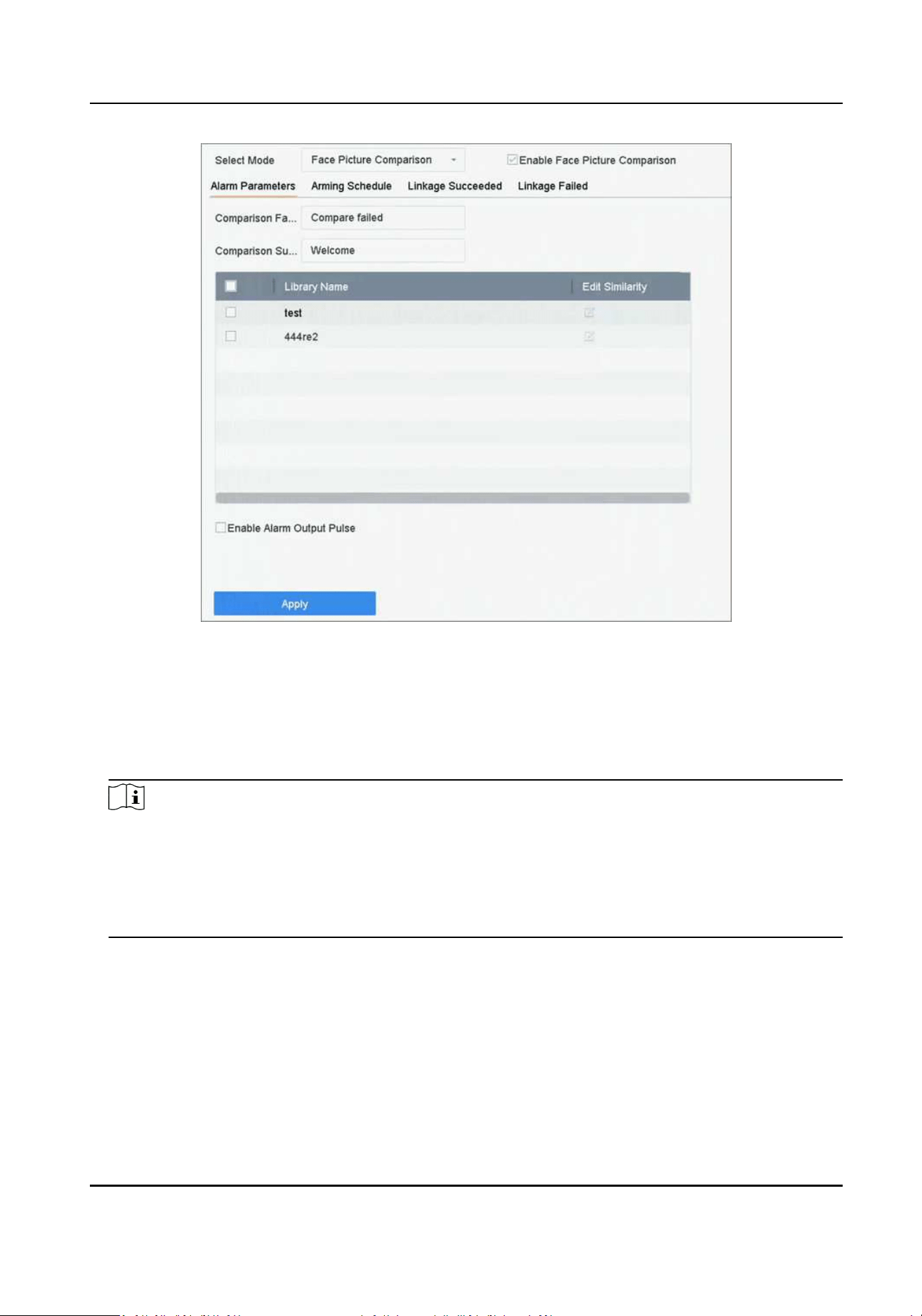
Figure 7-6 Face Picture Comparison
4. Set Mode as Face Picture Comparison.
5. Oponal: Check Enable Non-Real-Time Mode. For places with a high ow of people, the device
processing speed may not be fast enough, Non-Real-Time Mode will save the real-me pictures
as cache, and process them later when engine has free resource. Aer enabling this funcon, all
channels will be able to support face picture comparison.
Note
●
When Non-Real-Time Mode is enabled, the linkage method will only support Nofy
Surveillance Center.
●
Non-Real-Time Mode will not trigger real-me alarm, so Arming Schedule is unavailable.
●
You can search the comparison event results in File Management → Smart Search → Face
Search → Search by Event .
6. Check Enable Face Picture Comparison.
7. Oponal: Check Save VCA Picture to save the captured pictures of VCA detecon. Aer the face
picture comparison is enabled, the comparison results will be uploaded for face comparison
alarm. If the comparison produced a match, both the real-me face picture and the target
picture from the library will be uploaded. If no match is produced, the real-me face picture is
uploaded to center only.
8. Oponal: Set Comparison Failed Prompt, Comparison Succeeded Prompt, and Enable Alarm
Output Pulse.
Network Video Recorder User Manual
87

Comparison Failed Prompt
It will display the prompt in live view Target (with Facial Detecon checked) or Facial
Recognion when face picture comparison failed. You can click in live view to enter Facial
Recognion interface.
Comparison Succeeded Prompt
It will display the prompt in Facial Recognion when face picture comparison succeeded. You
can click in live view to enter person passing interface.
Enable Alarm Output Pulse
It is usually linked with a gate. When a person is passing a gate, if the comparison succeeded,
it will trigger a pulse to open the gate. The pulse is between 100 to 900 ms. You can set Alarm
Output Pulse (ms) in System → Event → Normal Event → Alarm Output .
9. Select face picture libraries and set similarity.
10. Set the arming schedule. Refer to Congure Arming Schedule .
11. Set the linkage acons when face picture comparison succeeded or failed. Refer to Congure
Linkage Acons .
12. Oponal: Congure face grading parameters. Refer to Face Grading Conguraon .
13. Click Apply to save the sengs.
Congure Stranger Alarm
Compare detected face pictures with specied face picture library. Trigger alarm when comparison
failed.
Steps
1. Go to Smart Analysis → Smart Event Sengs → Facial Recognion .
2. Select a camera.
3. Click Face Picture Comparison.
Network Video Recorder User Manual
88
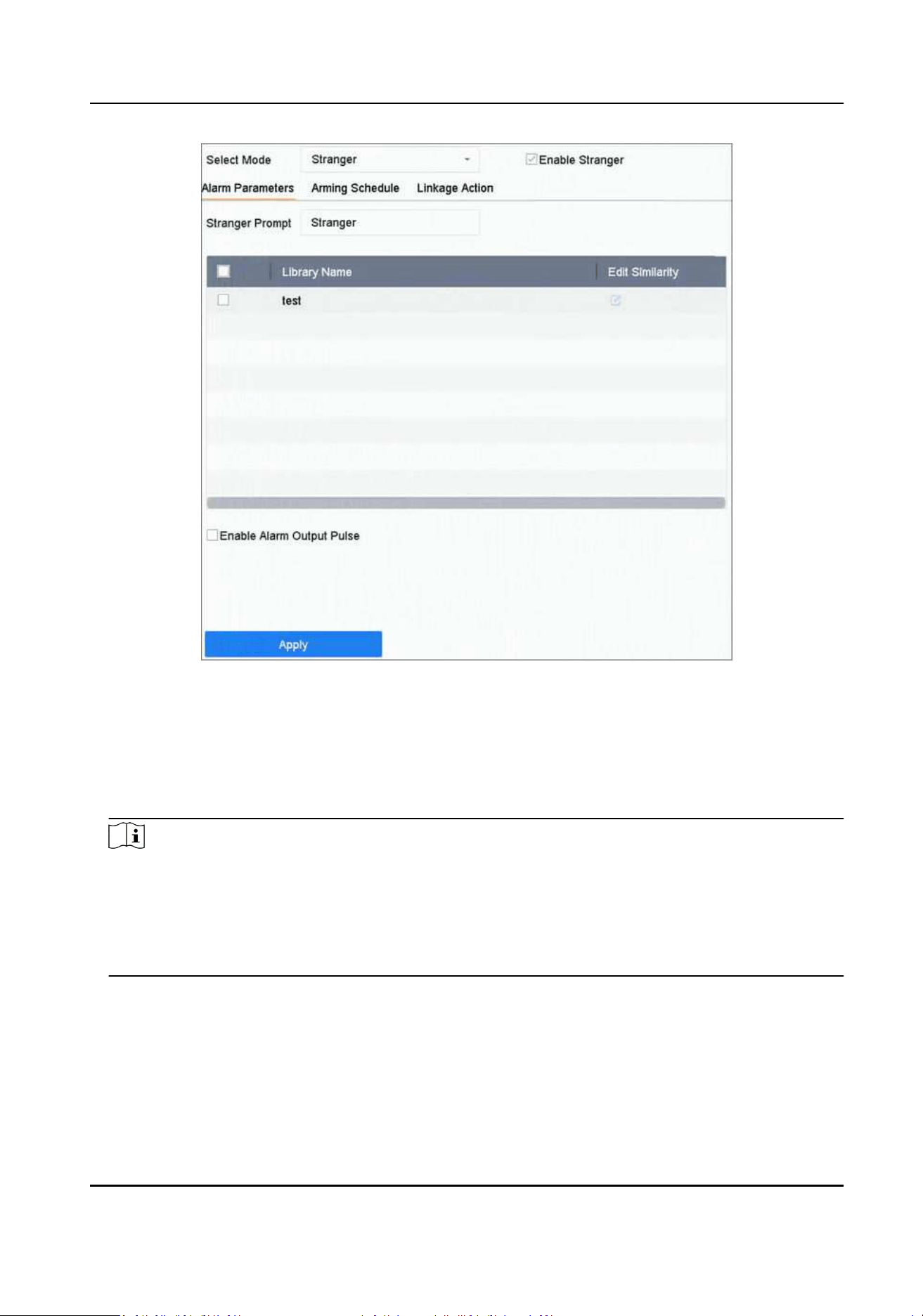
Figure 7-7 Face Picture Comparison
4. Select Mode as Stranger.
5. Oponal: Check Enable Non-Real-Time Mode. For places with a high ow of people, the device
processing speed may not be fast enough, Non-Real-Time Mode will save the real-me pictures
as cache, and process them later when engine has free resource. Aer enabling this funcon, all
channels will be able to support face picture comparison.
Note
●
When Non-Real-Time Mode is enabled, the linkage method will only support Nofy
Surveillance Center.
●
Non-Real-Time Mode will not trigger real-me alarm, so Arming Schedule is unavailable.
●
You can search the comparison event results in File Management → Smart Search → Face
Search → Search by Event .
6. Check Enable Stranger.
7. Oponal: Check Save VCA Picture to save the captured pictures of VCA detecon. Aer the face
picture comparison is enabled, the comparison results will be uploaded for face comparison
alarm. If the comparison produced a match, both the real-me face picture and the target
picture from the library will be uploaded. If no match is produced, the real-me face picture is
uploaded to center only.
Network Video Recorder User Manual
89

8. Oponal: Set Stranger Prompt. It will display the prompt in live view Target (Facial Detecon)
when comparison failed.
Stranger Prompt
It will display the prompt in live view Target (with Facial Detecon checked) when face
picture comparison failed.
Enable Alarm Output Pulse
It is usually linked with a gate. When a person is passing a gate, if the comparison succeeded,
it will trigger a pulse to open the gate. The pulse is between 100 to 900 ms. You can set Alarm
Output Pulse (ms) in System → Event → Normal Event → Alarm Output .
9. Select face picture libraries and set similarity.
10. Set the arming schedule. Refer to Congure Arming Schedule .
11. Set the linkage acons. Refer to Congure Linkage Acons .
12. Oponal: Congure face grading parameters. Refer to Face Grading Conguraon .
13. Click Apply to save the sengs.
7.4.5 People Frequency Alarm
You can only congure people frequency alarm via web browser.
Frequently Appeared Person Alarm
It will trigger alarm when a person has appeared at a high frequency.
Steps
1. Go to Conguraon → Event → People Frequency → Frequently Appeared Person .
Network Video Recorder User Manual
90

Figure 7-8 Frequently Appeared Person
2. Check Enable.
3. Set Capture Interval, Frequency Threshold, and Stascs Cycle.
Capture Interval
When a person has appeared several mes within the capture interval, it only counts 1 me
for this person.
Frequency Threshold
It will trigger alarm when the frequency has exceeded the threshold.
Stascs Cycle
Time period for counng the people frequency. For example, if the stascs cycle is 7 days,
device will count people frequency in the last 7 days (including today), if a person has
exceeded the frequency threshold in the last 7 days, it will trigger alarm.
4. Click Linked Channel to select channel.
5. Click Linked Face Picture Library to select face picture library.
6. Set similarity for the selected library.
7. Set strategy as Filter or Alarm.
Filter
If the face picture similarity has exceeded the value, the face picture is considered as an
exisng member in the library, which will not trigger alarm.
Alarm
It will trigger alarm when the face picture similarity and frequency has exceeded the threshold.
Network Video Recorder User Manual
91
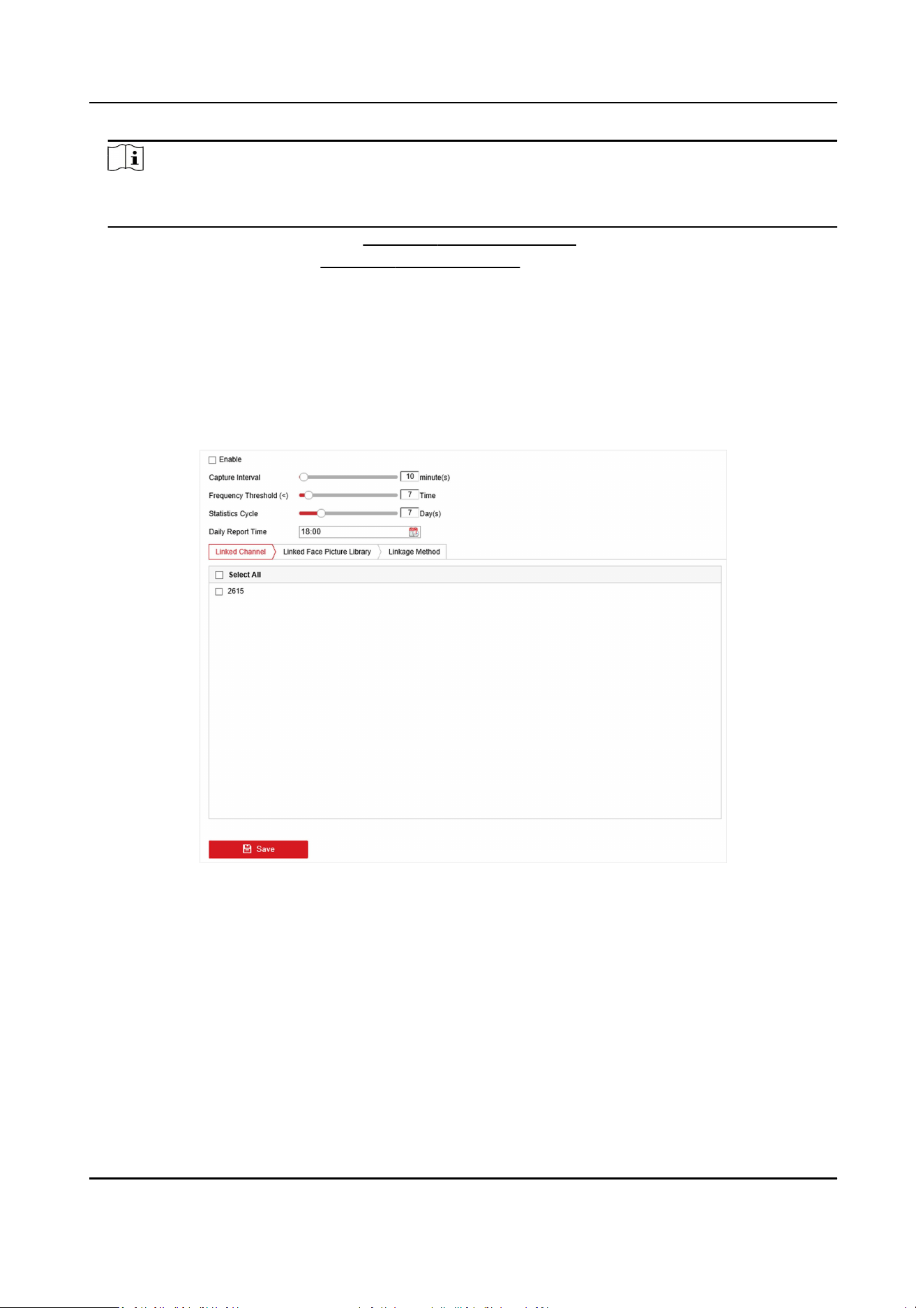
Note
All unrecognized face pictures will be added to Strangers library, so that strangers can also
trigger the frequently appeared person alarm, and they use the similarity of Strangers library.
8. Set the arming schedule. Refer to Congure Arming Schedule .
9. Set linkage acons. Refer to Congure Linkage Acons .
10. Click Save.
Rarely Appeared Person Alarm
It will trigger an alarm when a person has appeared at a low frequency.
Steps
1. Go to Conguraon → Event → People Frequency → Low Frequency Person .
Figure 7-9 Rarely Appeared Person
2. Check Enable.
3. Set Capture Interval, Frequency Threshold, Stascs Cycle, and Daily Report Time.
Capture Interval
When a person has appeared several mes within the capture interval, the device only
counts 1 me for this person.
Frequency Threshold
It will trigger an alarm when the frequency reaches the threshold.
Stascs Cycle
Network Video Recorder User Manual
92

Time period for counng the people frequency. For example, if the stascs cycle is 7 days,
device will count people frequency in the last 7 days (including today), if a person has not
exceeded the frequency threshold in the last 7 days, it will trigger an alarm.
Daily Report Time
Daily report of low frequency person stascs at the predened me.
4. Click Linked Channel to select channel.
5. Click Linked Face Picture Library to select face picture library.
6. Set linkage acons. Refer to Congure Linkage Acons .
7. Click Save.
Aggregaon Strategy
Aggregaon strategy parameters are used for frequently appeared person alarm. This funcon is
usually used for technical support, please contact our technical support before eding parameters.
You can congure the similarity and score via web browser in Conguraon → VCA Conguraon
→ Aggregaon Strategy .
When a person has two or more face pictures in the face library, the aggregaon strategy funcon
will aggregate facial features from these face pictures, so as to improve the accuracy of facial
recognion and alarm.
7.4.6 Face Picture Search
Search by Face Picture Comparison Event
Search face picture by face picture comparison results.
Steps
1. Go to Smart Analysis → Smart Search → Face → Search by Event .
2. Set the start me and end me.
3. Select a channel.
4. Select Event Type as Face Picture Comparison.
5. Click Start Search. The search result list displays 1 channel.
6. Click Channel to select a channel as your desire. It will display search results for the selected
channel.
What to do next
Refer to
View Searching Result .
Search by Uploaded Picture
You can search the face pictures by uploaded picture.
Network Video Recorder User Manual
93
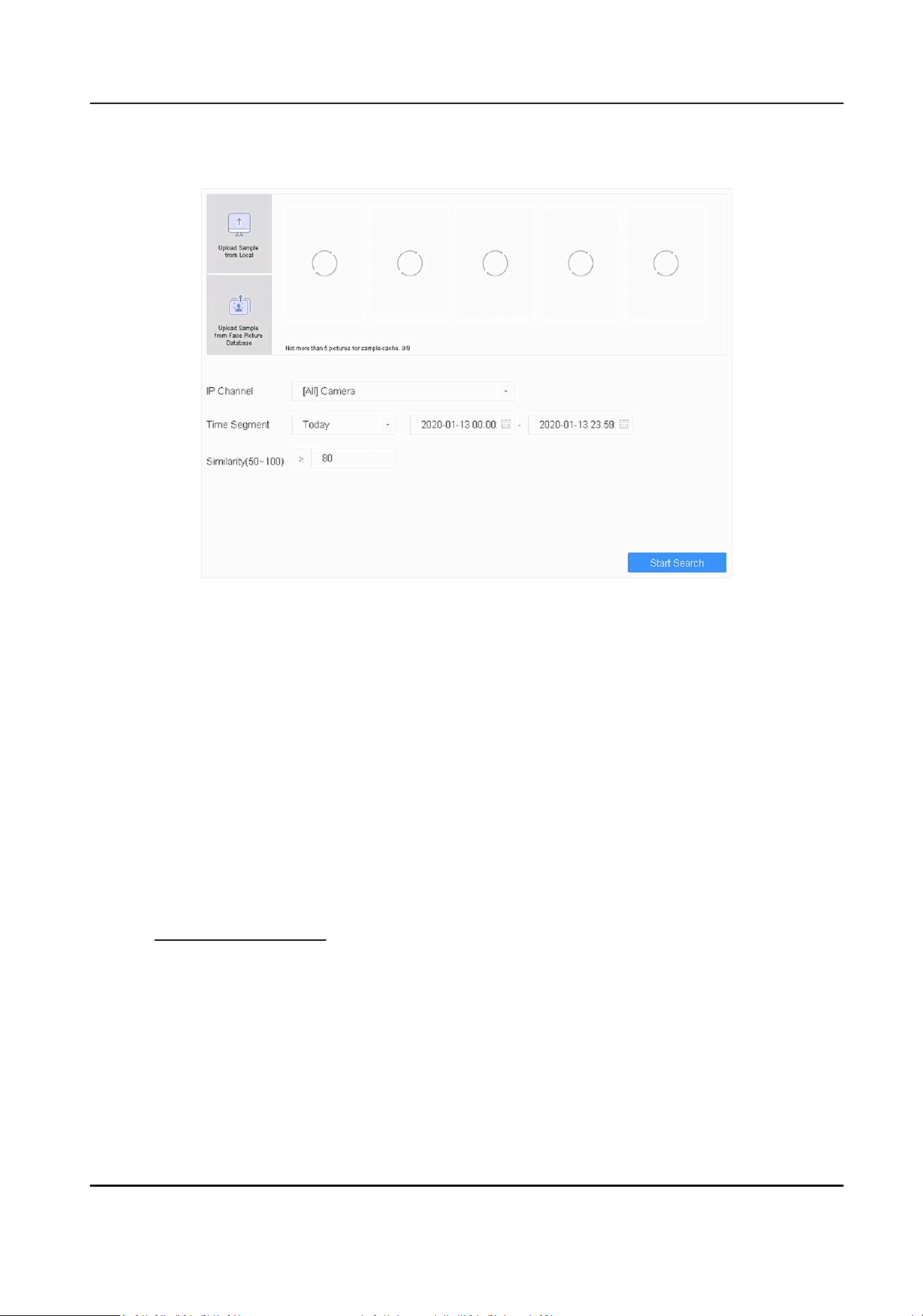
Steps
1. Go to Smart Analysis → Smart Search → Face → Search by Picture .
Figure 7-10 Search by Uploaded Picture
2. Select a channel.
3. Select face pictures for search.
-
Click Upload Sample from Local and select face pictures from your local directory.
-
Click Upload Sample from Face Picture Database and select face pictures from created face
picture libraries.
4. Set the start me and end me.
5. Set the Similarity value (range: 50 to 100). The device will analyze the similarity between
samples and face pictures in the library, and show pictures of which are higher than the
similarity.
6. Click Start Search. The search result list displays 1 channel.
7. Click Channel to select a channel as your desire. It will display search results for the selected
channel.
What to do next
Refer to
View Searching Result .
Search by Name
You can search face picture by name, if you know the name of the person.
Steps
1. Go to Smart Analysis → Smart Search → Face → Search by Name .
Network Video Recorder User Manual
94

Figure 7-11 Search by Name
2. Set the start me and end me of the face pictures to search.
3. Select a channel.
4. Enter a name.
5. Click Start Search. If the name is duplicated in the face picture library, you will have to select a
name. The search result list displays 1 channel.
6. Click Channel to select a channel as your desire. It will display search results for the selected
channel.
What to do next
Refer to
View Searching Result .
Search by Appearance
Search face picture by appearance.
Steps
1. Go to Smart Analysis → Smart Search → Face → Search by Appearance .
2. Set search condions.
3. Click Start Search. The search result list displays 1 channel.
4. Click Channel to select a channel as your desire. It will display search results for the selected
channel.
What to do next
Refer to
View Searching Result .
Network Video Recorder User Manual
95

View Searching Result
●
Double click a le to view the related video.
●
Click Add to Face Database to add the selected le(s) to a face picture library.
●
Click Add to Sample to add the select le(s) as sample picture(s). You can use the sample
picture(s) to search other pictures. Refer to Search by Uploaded Picture .
●
Click Export to export the selected le(s) to a backup device. You can click Select All to select all
les.
Note
●
You can click to view export progress.
●
You can click to return to search interface.
7.5 Perimeter Protecon
Go to Smart Analysis → Engine Sengs → Engine Conguraon . Congure at least one engine
usage as Perimeter Protecon. Refer to Engine Conguraon for details.
Note
The chapter is only available for certain models.
7.5.1 Line Crossing Detecon
Line crossing detecon detects people, vehicles, and objects crossing a set virtual line. The
detecon direcon can be set as bidireconal, from le to right or from right to le.
Steps
1. Go to Smart Analysis → Smart Event Sengs → Perimeter Protecon .
2. Select a camera.
3. Click Line Crossing.
Network Video Recorder User Manual
96
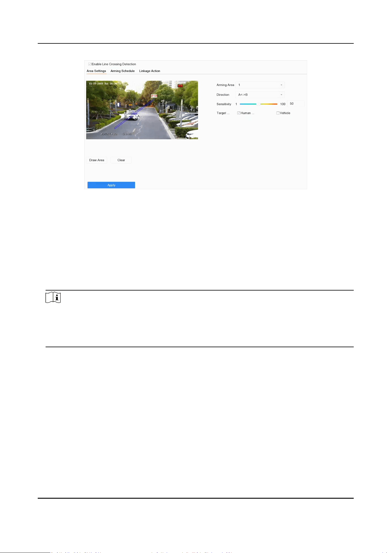
Figure 7-12 Line Crossing Detecon
4. Check Enable Line Crossing Detecon.
5. Oponal: Check Save VCA Picture to save the captured pictures of line crossing detecon.
6. Oponal: Check Enable AI by Device.
The device will analyze the video, and cameras only transmit video stream.
7. Oponal: Set Shield Area if Enable AI by Device is checked.
Shield Area
Aer a shield area is set, the device will not analyze target behavior in the area, so that the
perimeter protecon events will not be triggered within the area.
Note
●
Shield area is only valid for the selected camera.
●
Aer a shield area is set, it will take eect for all perimeter protecon events, including line
crossing detecon, intrusion detecon, region entrance detecon, and region exing
detecon.
1) Click Shield Area.
2) Check Enable Shield Area.
3) Select Shield Area.
4) Click Draw Area, and draw a quadrilateral in the preview window.
5) Right click your mouse to nish drawing.
6) Click OK.
8. Set the line crossing detecon rules and detecon areas.
1) Select an arming area.
2) Select Direcon as A<->B, A->B, or A<-B.
A<->B
Only the arrow on the B side shows. When an object goes across the congured line with
both direcons can be detected and alarms are triggered.
Network Video Recorder User Manual
97

A->B
Only the object crossing the congured line from the A side to the B side can be detected.
B->A
Only the object crossing the congured line from the B side to the A side can be detected.
3) Set the detecon sensivity. The higher the value is, the more easily the detecon alarm can
be triggered.
4) Click Draw Region.
5) Draw a virtual line in the preview window.
9. Oponal: Draw the maximum size/minimum size for targets.
Note
Only the targets in the size ranging from maximum size to minimum size will trigger line crossing
detecon.
1) Click Max. Size/Min. Size.
2) Draw an area in preview window.
3) Click Stop Drawing.
10. Oponal: Select Detecon Target as Human or Vehicle to discard alarms which are not
triggered by human or vehicle.
11. Set the arming schedule. Refer to Congure Arming Schedule .
12. Set linkage acons. Refer to Congure Linkage Acons .
13. Click Apply.
7.5.2 Intrusion Detecon
Intrusion detecon funcon detects people, vehicles or other objects that enter and loiter in a pre-
dened virtual region. Specic acons can be taken when an alarm is triggered.
Steps
1. Go to Smart Analysis → Smart Event Sengs → Perimeter Protecon .
2. Select a camera.
3. Click Intrusion.
Network Video Recorder User Manual
98
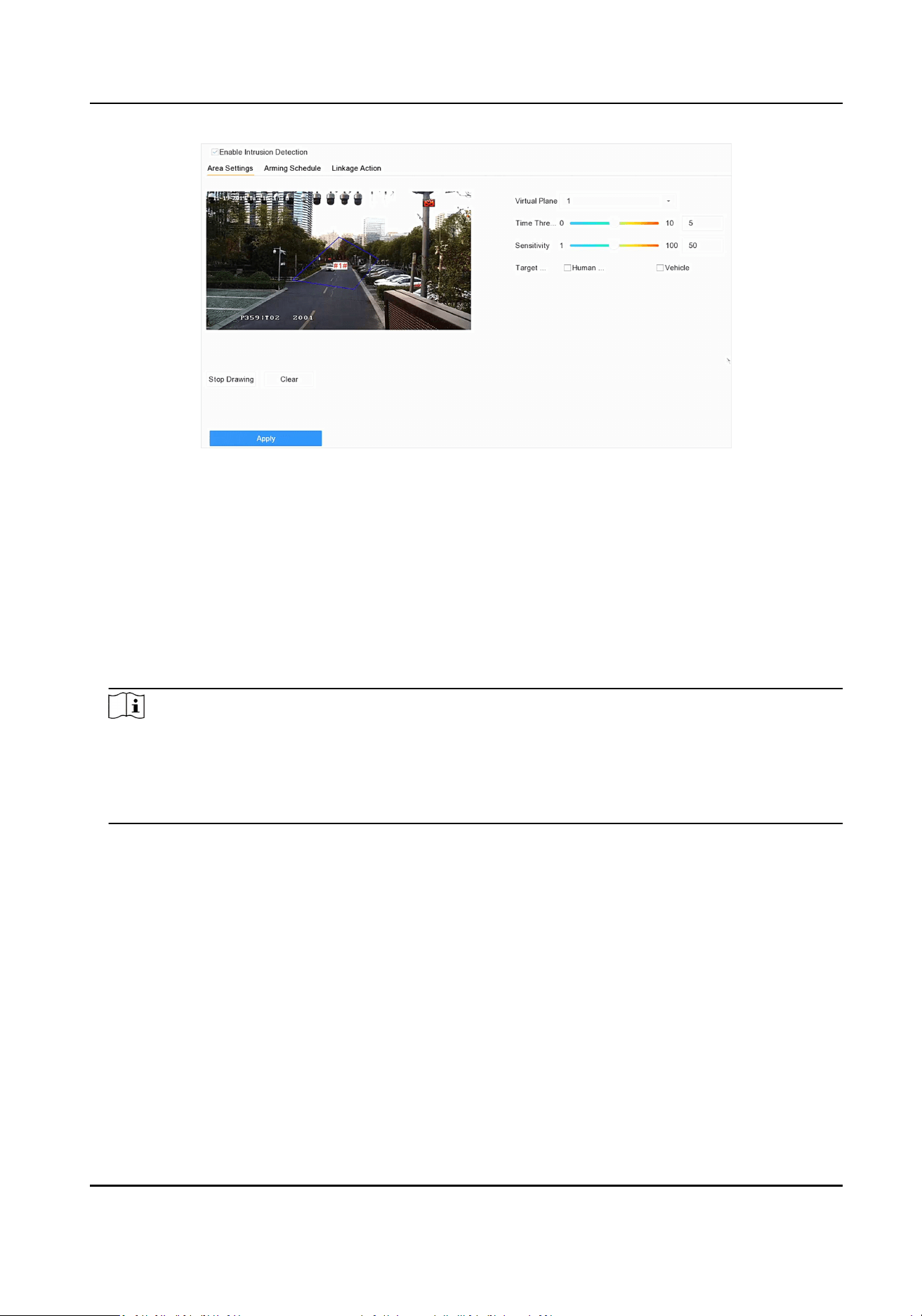
Figure 7-13 Intrusion Detecon
4. Check Enable Intrusion Detecon.
5. Oponal: Check Save VCA Picture to save the captured intrusion detecon pictures.
6. Oponal: Check Enable AI by Device.
The device will analyze the video, and cameras only transmit video stream.
7. Oponal: Set Shield Area if Enable AI by Device is checked.
Shield Area
Aer a shield area is set, the device will not analysis target behavior in the area, so that the
perimeter protecon events will not be triggered within the area.
Note
●
Shield area is only valid for the selected camera.
●
Aer a shield area is set, it will take eect for all perimeter protecon events, including line
crossing detecon, intrusion detecon, region entrance detecon, and region exing
detecon.
1) Click Shield Area.
2) Check Enable Shield Area.
3) Select Shield Area.
4) Click Draw Area, and draw a quadrilateral in the preview window.
5) Right click your mouse to nish drawing.
6) Click OK.
8. Set the detecon rules and detecon areas.
1) Select a virtual panel. Up to 4 virtual panels are selectable.
2) Set Time Threshold, and Sensivity.
Time Threshold
The me an object loiter in the region. When the duraon of the object in the dened
detecon area exceeds the threshold, the device will trigger an alarm.
Network Video Recorder User Manual
99
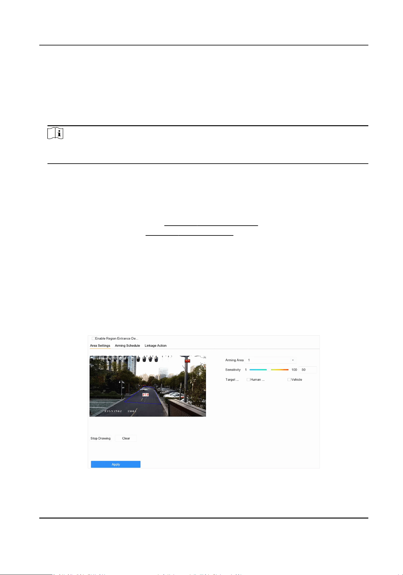
Sensivity
Sensivity is the object size which is able to trigger an alarm. The higher the sensivity is,
the more easily the detecon alarm will be triggered.
3) Click Draw Area.
4) Draw a quadrilateral in the preview window.
9. Oponal: Draw the maximum size/minimum size for targets.
Note
Only the targets in the size ranging from maximum size to minimum size will trigger Intrusion
detecon.
1) Click Max. Size/Min. Size.
2) Draw an area in preview window.
3) Click Stop Drawing.
10. Oponal: Select Detecon Target as Human or Vehicle to discard alarms which are not
triggered by human or vehicle.
11. Set the arming schedule. Refer to Congure Arming Schedule .
12. Set linkage acons. Refer to Congure Linkage Acons .
13. Click Apply.
7.5.3 Region Entrance Detecon
Region entrance detecon detects objects that enter a predened virtual region.
Steps
1. Go to Smart Analysis → Smart Event Sengs → Perimeter Protecon .
2. Select a camera.
3. Click Region Entrance Detecon.
Figure 7-14 Region Entrance Detecon
Network Video Recorder User Manual
100

4. Check Enable Region Entrance Detecon.
5. Oponal: Check Save VCA Picture to save the captured pictures of region entrance detecon
pictures.
6. Oponal: Check Enable AI by Device.
The device will analyze the video, and cameras only transmit video stream.
7. Oponal: Set Shield Area if Enable AI by Device is checked.
Shield Area
Aer a shield area is set, the device will not analysis target behavior in the area, so that the
perimeter protecon events will not be triggered within the area.
Note
●
Shield area is only valid for the selected camera.
●
Aer a shield area is set, it will take eect for all perimeter protecon events, including line
crossing detecon, intrusion detecon, region entrance detecon, and region exing
detecon.
1) Click Shield Area.
2) Check Enable Shield Area.
3) Select Shield Area.
4) Click Draw Area, and draw a quadrilateral in the preview window.
5) Right click your mouse to nish drawing.
6) Click OK.
8. Set detecon rules and detecon areas.
1) Select Arming Region. Up to 4 regions are selectable.
2) Set Sensivity. The higher the value is, the easier the detecon alarm will be triggered. Its
range is [0-100].
3) Click Draw Region, and draw a quadrilateral in the preview window.
9. Oponal: Draw the maximum size/minimum size for targets. Only the targets in the size ranging
from maximum size to minimum size will trigger line crossing detecon.
1) Click Max. Size/Min. Size.
2) Draw an area in preview window.
3) Click Stop Drawing.
10. Oponal: Select Detecon Target as Human or Vehicle to discard alarms which are not
triggered by human or vehicle.
11. Set the arming schedule. Refer to
Congure Arming Schedule .
12. Set linkage acons. Refer to Congure Linkage Acons .
13. Click Apply.
7.5.4 Region Exing Detecon
Region exing detecon detects objects that exit from a predened virtual region.
Network Video Recorder User Manual
101
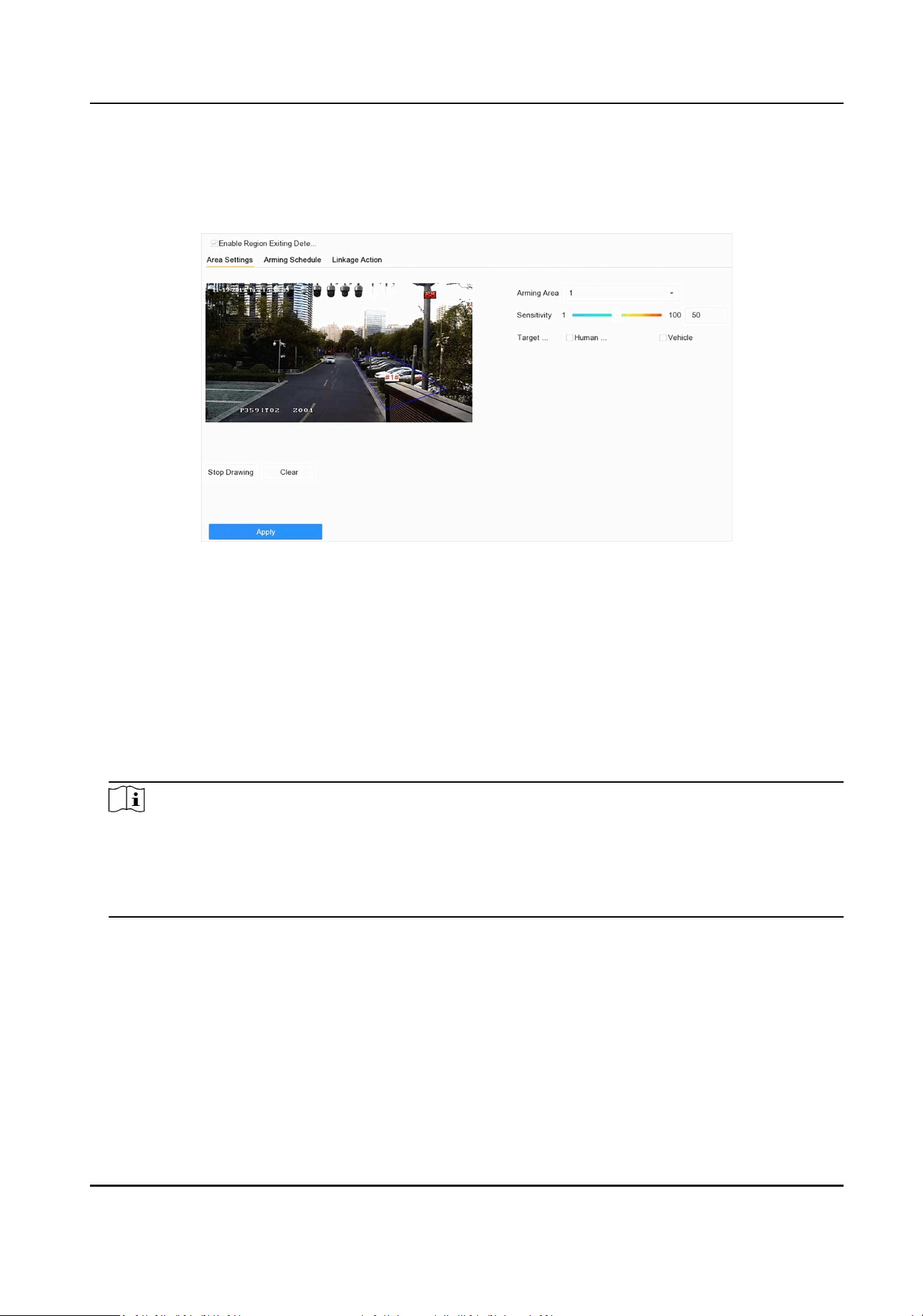
Steps
1. Go to Smart Analysis → Smart Event Sengs → Perimeter Protecon .
2. Select a camera.
3. Click Region Exing.
Figure 7-15 Region Exing Detecon
4. Check Enable Region Exing Detecon.
5. Oponal: Check Save VCA Picture to save the captured region exing detecon pictures.
6. Oponal: Check Enable AI by Device.
The device will analyze the video, and cameras only transmit video stream.
7. Oponal: Set Shield Area if Enable AI by Device is checked.
Shield Area
Aer a shield area is set, the device will not analysis target behavior in the area, so that the
perimeter protecon events will not be triggered within the area.
Note
●
Shield area is only valid for the selected camera.
●
Aer a shield area is set, it will take eect for all perimeter protecon events, including line
crossing detecon, intrusion detecon, region entrance detecon, and region exing
detecon.
1) Click Shield Area.
2) Check Enable Shield Area.
3) Select Shield Area.
4) Click Draw Area, and draw a quadrilateral in the preview window.
5) Right click your mouse to nish drawing.
6) Click OK.
8. Follow these steps to set the detecon rules and detecon areas.
1) Select Arming Region. Up to 4 regions are selectable.
Network Video Recorder User Manual
102

2) Set Sensivity. The higher the value is, the more easily the detecon alarm will be triggered.
Its range is [0-100].
3) Click Draw Region and draw a quadrilateral in the preview window.
9. Oponal: Draw the maximum size/minimum size for targets. Only the targets in the size ranging
from maximum size to minimum size will trigger line crossing detecon.
1) Click Max. Size/Min. Size.
2) Draw an area in preview window.
3) Click Stop Drawing.
10. Oponal: Select Detecon Target as Human or Vehicle to discard alarms which are not
triggered by human or vehicle.
11. Set the arming schedule. Refer to Congure Arming Schedule .
12. Set linkage acons. Refer to Congure Linkage Acons .
13. Click Apply.
7.6 Human Body Detecon
Go to Smart Analysis → Engine Sengs → Engine Conguraon . Congure at least one engine
usage as Picture Recognion-Human Body. Refer to Engine Conguraon for details.
Go to Smart Analysis → Engine Sengs → Task Conguraon to enable the task for camera. For
details, refer to Task Conguraon for details.
Note
The chapter is only available for certain models of iDS series.
7.6.1 Human Body Detecon
The human body detecon enables to detect the human body appearing in the monitoring scene,
and capture the human body pictures.
Before You Start
Ensure the connected camera supports the human body detecon.
Steps
1. Go to Smart Analysis → Smart Event Sengs → Other Events .
2. Select a camera.
3. Click Human Body.
4. Oponal: For IP camera does not support human body detecon, Check Enable Local Human
Body Detecon. Then the device will consume its decoding resource to execute human body
detecon. Before enabling the funcon, go to Smart Analysis → Engine Sengs → Engine
Conguraon to select at least one engine as Video Structuralizaon-Real-Time.
5. Check Save VCA Picture to save the captured pictures of human body detecon.
Network Video Recorder User Manual
103
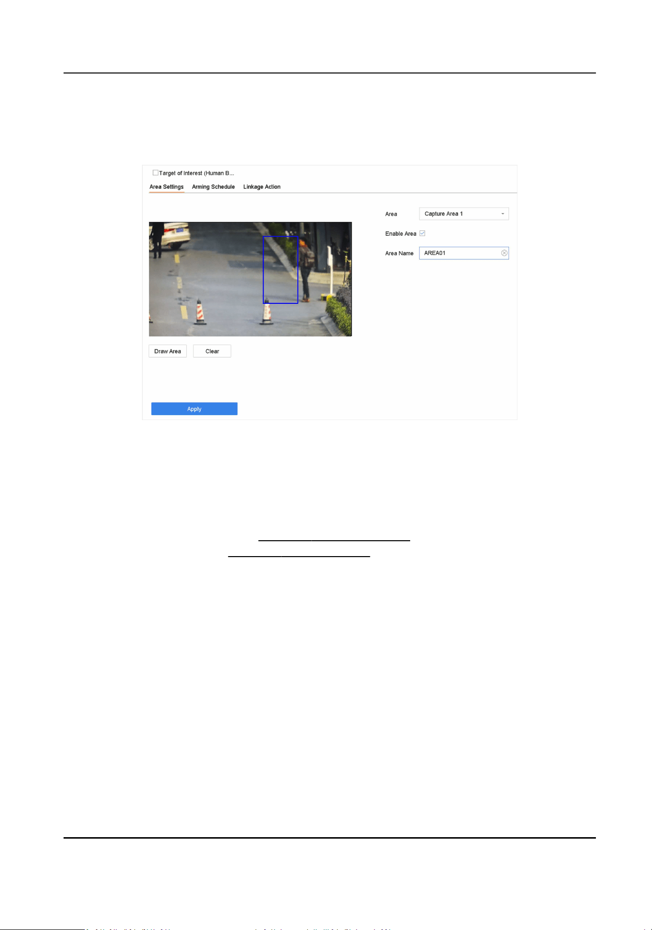
6. Check Target of Interest (Human Body) to discard non-human body pictures and videos which
are not triggered by human body detecon. The feature is only available for local human body
detecon.
7. Set detecon area.
Figure 7-16 Human Body Detecon
1) Select the detecon area to congure from the Area drop-down list. Up to 8 detecon areas
are selectable.
2) Check Enable Area to enable the selected detecon area.
3) Edit the area name in Scene Name. The scene name can contain up to 32 characters.
4) Click Draw Area to draw a quadrilateral in the preview window and then click Stop Drawing.
8. Set the arming schedule. Refer to
Congure Arming Schedule .
9. Set linkage acons. Refer to Congure Linkage Acons .
10. Click Apply to acvate the sengs.
7.6.2 Human Body Search
Search by Human Body Event
Search pictures by human body detecon alarms.
Steps
1. Go to Smart Analysis → Smart Search → Human → Search by Event .
2. Set the start me and end me.
3. Select a channel.
4. Select Event Type as Human Body Alarm.
5. Click Start Search. The search result list displays 1 channel.
Network Video Recorder User Manual
104

6. Click Channel to select a channel as your desire. It will display search results for the selected
channel.
7. Oponal: Export search results.
1) Select result le(s) from the search result interface, or check Select All to select all les.
2) Click Export to export the selected le(s) to a backup device.
Note
●
You can click to view export progress.
●
You can click to return to search interface.
Search by Appearance
Search human body pictures according to manually specied search condions.
Steps
1. Go to Smart Analysis → Smart Search → Human → Search by Appearance .
2. Specify search condions.
3. Click Start Search. The search result list displays 1 channel.
4. Click Channel to select a channel as your desire. It will display search results for the selected
channel.
5. Oponal: Export search results.
1) Select result le(s) from the search result interface, or check Select All to select all les.
2) Click Export to export the selected le(s) to a backup device.
Note
●
You can click to view export progress.
●
You can click to return to search interface.
Search by Uploaded Picture
To increase search accuracy, upload several pictures of one person to compare with captured
human body pictures.
Before You Start
Import human body pictures in a USB ash drive and connect it to device.
Steps
Note
●
When there are mulple targets exisng in the same picture, up to 30 target pictures can be
analyzed and displayed.
●
The maximum allowed picture size is 3840*2160.
●
The picture must be in JPG or JPEG format.
Network Video Recorder User Manual
105

●
The picture name (with the sux) cannot exceed 64 characters.
●
Ensure the picture you uploaded is clear and recognizable.
1. Go to Smart Analysis → Smart Search → Human → Search by Picture .
2. Select a channel.
3. Click Upload Sample.
4. Click Upload Sample from Local and select face pictures from your local directory.
5. Set the start me and end me.
6. Select a picture in USB ash drive, and click Import.
7. Select related pictures, and click Upload.
8. Specify search condions.
Similarity
Device will analyze the similarity between samples and face pictures in library and show
pictures the similarity of which are higher than the set one.
9. Click Start Search. The search result list displays 1 channel.
10. Click Channel to select a channel as your desire. It will display searching results for the selected
channel.
11. Oponal: Export search results.
1)Select result le(s) from the search result interface, or check Select All to select all les.
2)Click Export to export the selected le(s) to a backup device.
Note
●
You can click to view export progress.
●
You can click to return to search interface.
Add Search Result as Sample Picture
You can add searched human body pictures as sample pictures. And then search human body
pictures by the sample pictures.
Steps
1. Search human body pictures.
2. In search result interface, click to select a picture and click Add to Sample.
3. Return to search condion sengs interface, the selected sample will be listed.
7.7 Mul-Target-Type Detecon
Mul-target-type detecon enables the device to detect the faces, human bodies and vehicles
simultaneously in a scene.
Before You Start
Go to Smart Analysis → Engine Sengs → Engine Conguraon to congure at least one engine
usage as Video Structuralizaon-Real-Time. Refer to Engine Conguraon for details.
Network Video Recorder User Manual
106

Steps
Note
The chapter is only available for certain models of iDS series.
1. Go to Smart Analysis → Smart Event Sengs → Video Structuralizaon .
2. Select a camera.
3. Check Enable Mul-Target-Type Detecon.
4. Oponal: Check Save VCA Picture to save the captured intrusion detecon pictures.
5. Oponal: Check Enable NVR Smart Analysis. The device will analyze the video, cameras only
transmit video stream.
6. Set detecon area.
1) Click Draw Area.
2) Adjust the red frame on the image to draw the detecon area. It is full screen by default.
3) Click Stop Drawing.
7. Oponal: Set Capture Quality. The captured picture will be stored to the device, high quality
brings higher resoluon, but it takes larger storage space. Picture quality will not aect detecon
accuracy.
8. Set the arming schedule. Refer to Congure Arming Schedule .
9. Set the linkage method. Refer to Congure Linkage Acons .
10. Click Apply.
7.8 Vehicle Detecon
Vehicle detecon is available for the road trac monitoring. In vehicle detecon, the passed
vehicle can be detected and the picture of its license plate can be captured.
7.8.1 Congure Vehicle Detecon
Vehicle detecon, available in the road trac monitoring, is tend to detect the passed vehicle on
the road, and capture its license plate at the same me.
Steps
1. Go to Smart Analysis → Smart Event Sengs → Vehicle Detecon .
2. Select a camera.
3. Click Vehicle.
4. Check Enable Vehicle Detecon.
5. Oponal: Check Save VCA Picture to save the captured vehicle detecon pictures.
6. Congure rules, including Area Sengs, Picture, Overlay Content, and Blocklist and Allowlist.
Area Sengs
Up to 4 lanes are selectable.
Blocklist and Allowlist
Network Video Recorder User Manual
107

You can export the le rst to see its format, and edit it and import it to the device.
7. Click Apply.
Note
Refer to Network Camera User Manual for detailed instrucons for the vehicle detecon.
8. Set the arming schedule. Refer to Congure Arming Schedule .
9. Set the linkage acons. Refer to Congure Linkage Acons .
7.8.2 Vehicle Search
You can search and view the matched vehicle pictures.
Steps
1. Go to Smart Analysis → Smart Search → Vehicle .
2. Select a search method. For example, Search by Appearance, or Search by Event.
3. Select the IP camera for the vehicle search.
4. Set search condions.
5. Click Start Search. The search result list displays 1 channel.
6. Click Channel to select a channel as your desire. It will display searching results for the selected
channel.
7. Export search results.
1) Select result le(s) from the search result interface, or check Select All to select all les.
2) Click Export to export the selected le(s) to a backup device.
Note
●
You can click to view export progress.
●
You can click to return to search interface.
7.9 Object Thrown from Building
This funcon can idenfy the event of throwing objects from building and idenfy the real target.
Steps
1. Go to Conguraon → VCA → Object Thrown from Building via web browser.
Network Video Recorder User Manual
108
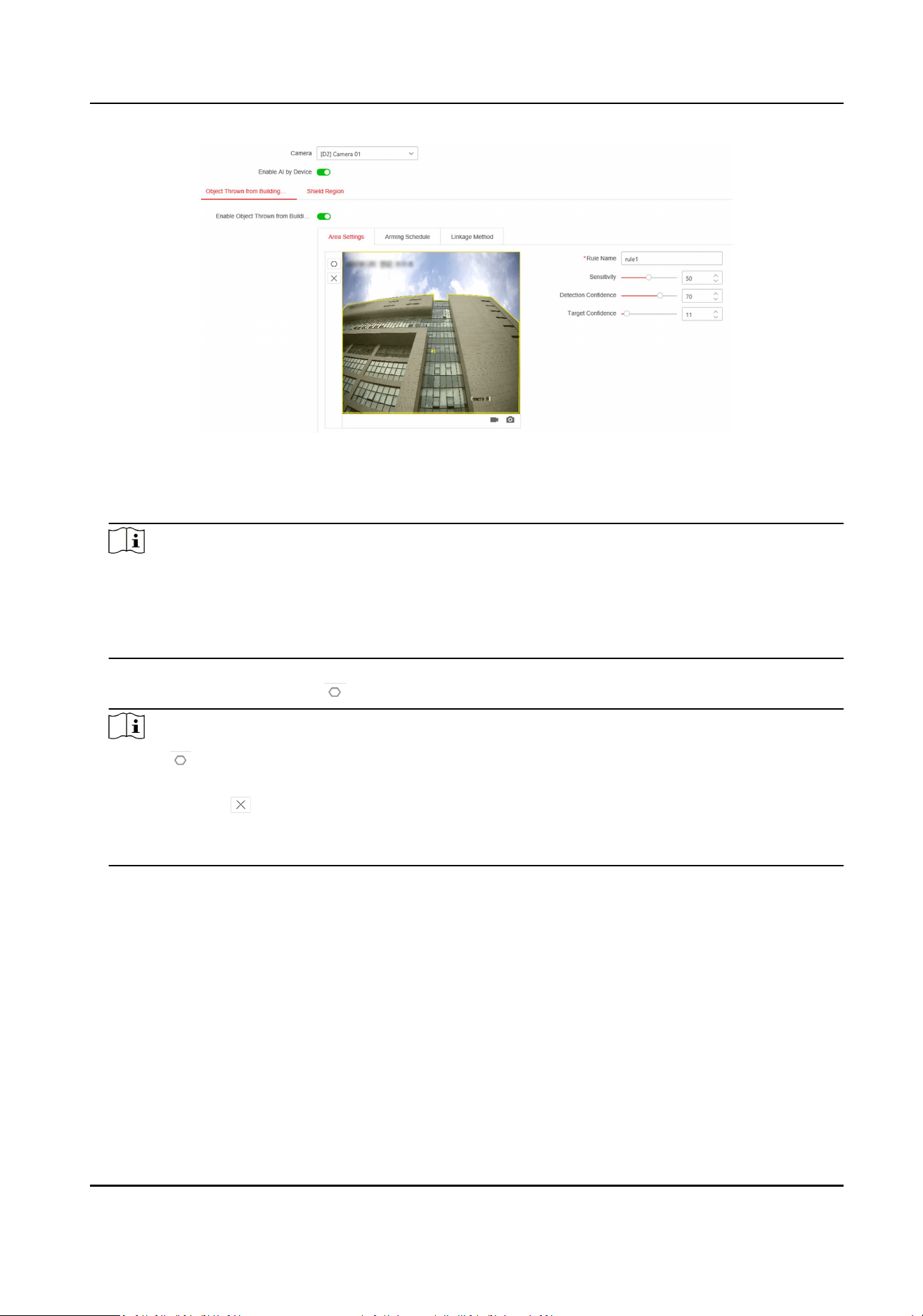
Figure 7-17 Object Thrown from Building
2. Select a camera.
3. Oponal: Check Enable AI by Device if this event shall be analyzed by the video recorder.
Note
●
If Enable AI by Device is turned on, at least one engine mode should be congured as Object
Thrown from Building.
●
If the selected camera can analyze this event by itself, you can choose to disable Enable AI by
Device, and let the camera do the analysis.
4. Check Enable Object Thrown from Building.
5. Click Area Sengs and click to draw rule area.
Note
a. Click to start drawing, le click each me on the screen to determine a vertex, right click
to stop drawing. The inside of the drawn polygon is the shielded area. If you make a mistake,
you can click and redraw.
b. It is recommended to draw the detecon area according to the outline of the building in the
screen.
6. Enter Rule Name. The default name is rule 1.
7. Set the detecon parameters.
Sensivity
Used to detect and lter object(s) that are denitely not thrown from the building. The higher
the value, the greater the possibility of a false alarm. Default value of 50 is recommended.
Detecon Condence
Used to detect suspicious object(s) in the detecon area. The lower the value, the easier it is
to detect the object in the video and make a judgment. Default value of 50 is recommended.
Target Condence
Network Video Recorder User Manual
109
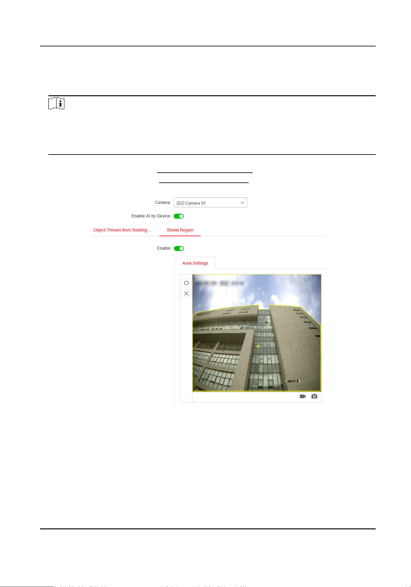
Used to determine if the target is a real object thrown from building. The lower the value, the
easier it is for a detected object in the video to be determined as an object thrown from
building, and the greater the likelihood of a false alarm. Default value of 50 is recommended.
Note
Default value is recommended at rst. Adjustment can be made if false alarm is triggered
frequently during the operaon. Target condence is recommended to be adjusted inially, and
detecon condence is recommended to be adjusted later if no sound detecon results
provided. If sll, there is no obvious eect, then adjust the sensivity.
8. Click Save.
9. Click Arming Schedule. Refer to Congure Arming Schedule .
10. Click Linkage Method. Refer to Congure Linkage Acons .
11. Congure Shield Region.
Figure 7-18 Shield Region
1)Click Shield Region.
2)Draw the region.
Network Video Recorder User Manual
110
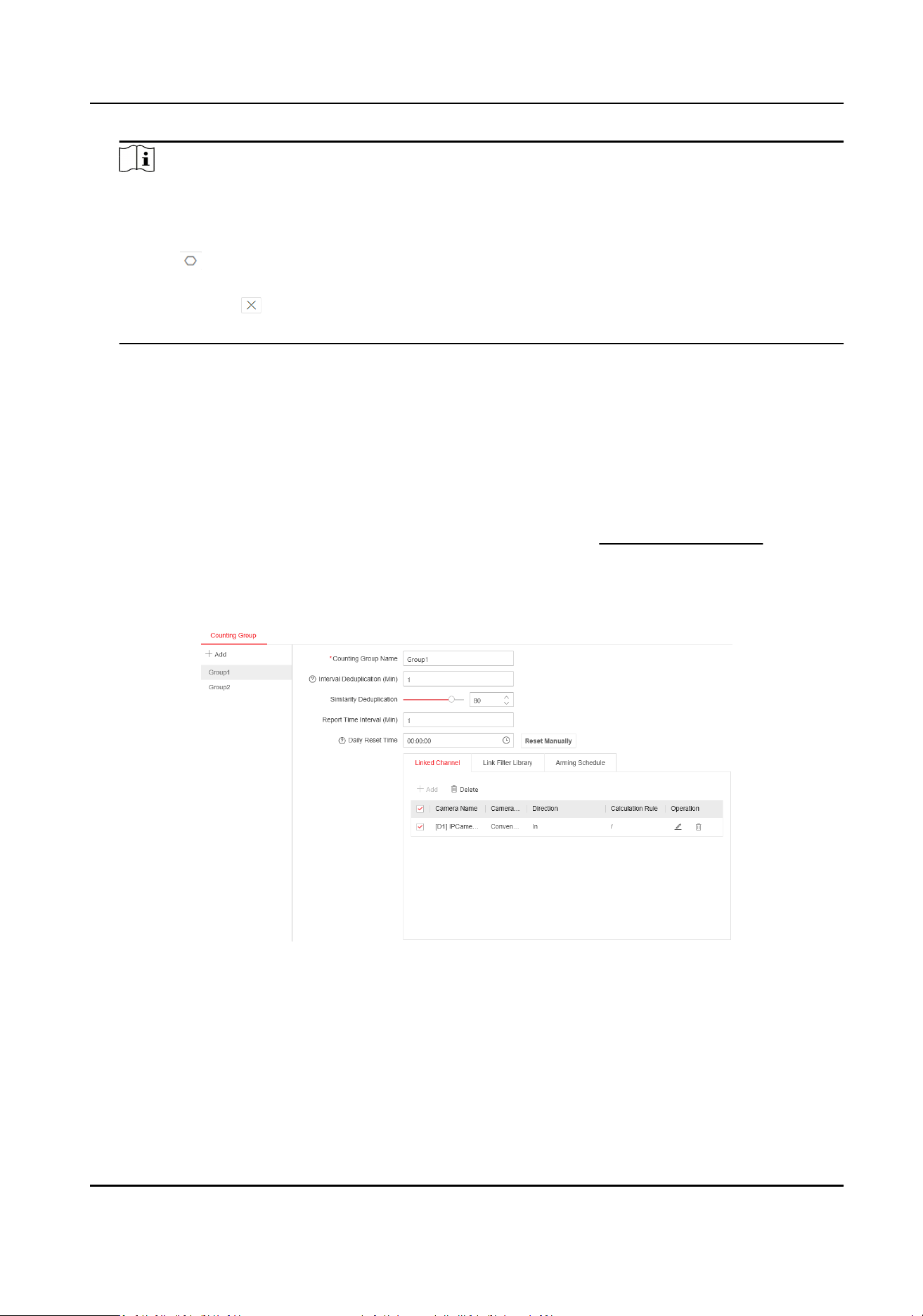
Note
a. If there are parts of the screen (either within or outside the detecon area) that do not
need to be detected (such as an area where the light jumps from me to me or leaves
oen dri by and trigger false alarms, etc.), you can draw it as a shield region.
b. Click to start drawing, le click each me on the screen to determine a vertex, right click
to stop drawing. The inside of the drawn polygon is the shielded area. If you make a mistake,
you can click and redraw.
c. 8 shield regions are supported.
12. Click Save.
7.10 Face Counng
The funcon is used to count the customer trac at specic scenes, such as supermarkets, shops,
etc.
Before You Start
Congure at least one engine usage as Facial Recognion. Refer to Engine Conguraon for
details.
Steps
1. Go to Conguraon → VCA → Face Counng → Counng Group via web browser.
Figure 7-19 Congure Face Counng
2. Click Add to add a group. A group can contain several cameras in the same scene.
3. Set group parameters.
Deduplicaon Interval
If a person appears several mes within one deduplicaon interval, the frequency will be
counted as one. Otherwise, the frequency will be counted as several mes.
Network Video Recorder User Manual
111
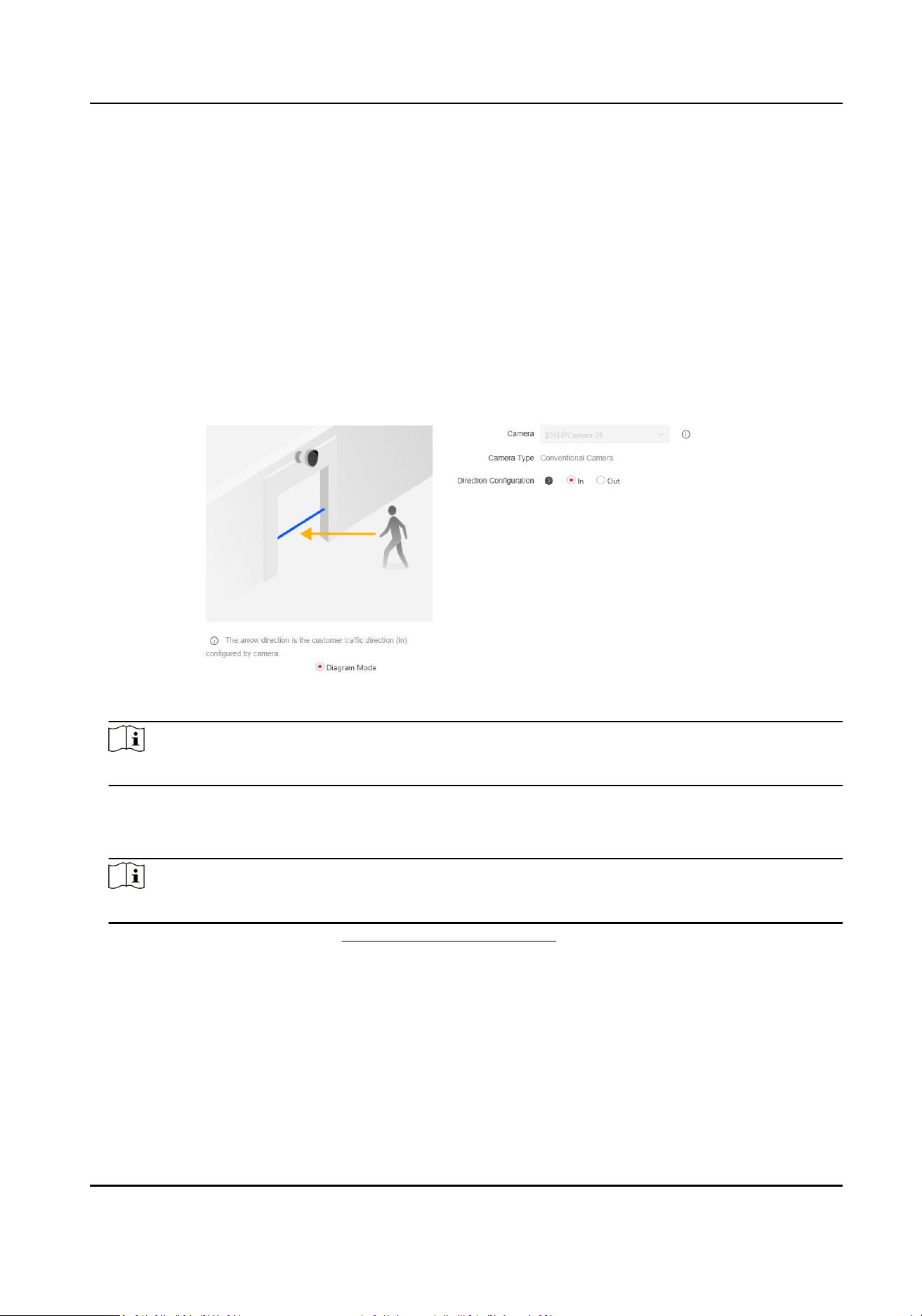
Deduplicaon Similarity
If several similar face pictures are captured in the scene, the device would regard the face
pictures as the same person when the similarity of these face pictures reaches the threshold.
Report Time Interval
The device will automacally report the counng data to the plaorm according to the me
interval.
Daily Reset Time
The device will reset the me of the deduplicaon library everyday.
4. Click Linked Channel.
5. Click Add to add channel(s) to the group.
6. Set the customer trac direcon.
Figure 7-20 Set Customer Trac Direcon
Note
The operaon interface may vary according to dierent camera types.
7. Oponal: Click Link Filter Library to select libraries for face picture ltering. If a captured face
picture is similar with the ones in the selected libraries, and its similarity reaches the threshold,
then the captured face picture will not be counted in to the customer trac data.
Note
You can congure face picture library in Conguraon → Face Picture Library via web browser.
8. Set Arming Schedule. Refer to Congure Arming Schedule for details.
9. Repeat above steps to add other groups or cameras as your desire.
10. Click Save.
What to do next
Counng results can be viewed through specied client sowares and plaorms.
Network Video Recorder User Manual
112

7.11 Target Detecon
In live view mode, the target detecon funcon can achieve smart detecon, facial detecon,
vehicle detecon, and human body detecon during the last 5 seconds and the following 10
seconds.
Steps
1. In live view mode, click Target to enter the target detecon interface.
2. Select dierent detecon types: smart detecon ( ), vehicle detecon ( ), facial detecon
( ), and human body detecon ( ).
Note
a. To enable the detecon of throwing objects from building, ensure smart detecon has
been checked. When the target is idened, the detected view will be displayed on the le.
Meanwhile, the box will display the detected object. (If there is a suspicious target, the
parabola will turn green. If there is a real target and the alarm is triggered, the parabola will
turn red. )
b. For thermal cameras, the temperature measurement event is in smart detecon ( ), the
face capture and facial temperature measurement are in facial detecon ( ).
3. Click to set alarm conguraon.
1) Select IP Camera(s) and IoT channel(s), and complete access control event display sengs.
Display Pop-Up
Enable this funcon, the pop-up including person type informaon, body temperature and
mask-wearing status (oponal) will be displayed once the alarm is triggered.
Mask Not Wearing Event
Temperature units including Celsius degree and Fahrenheit degree of the detected target
are available. Enable this funcon, when the target does not wear mask, the pop-up will
show yellow. Meanwhile, if the target has exceponal body temperature, the pop-up will
turn red.
4. Select the historical analysis ( ) or real-me analysis ( ) to obtain the results.
Note
The smart analysis results of the detecon are displayed in the list. Click a result in the list to
play the related video.
7.12 People Counng
People counng calculates the number of people entering or leaving a certain congured area and
creates daily/weekly/monthly/annual reports for analysis.
Steps
1. Go to Smart Analysis → Smart Report → Counng .
Network Video Recorder User Manual
113
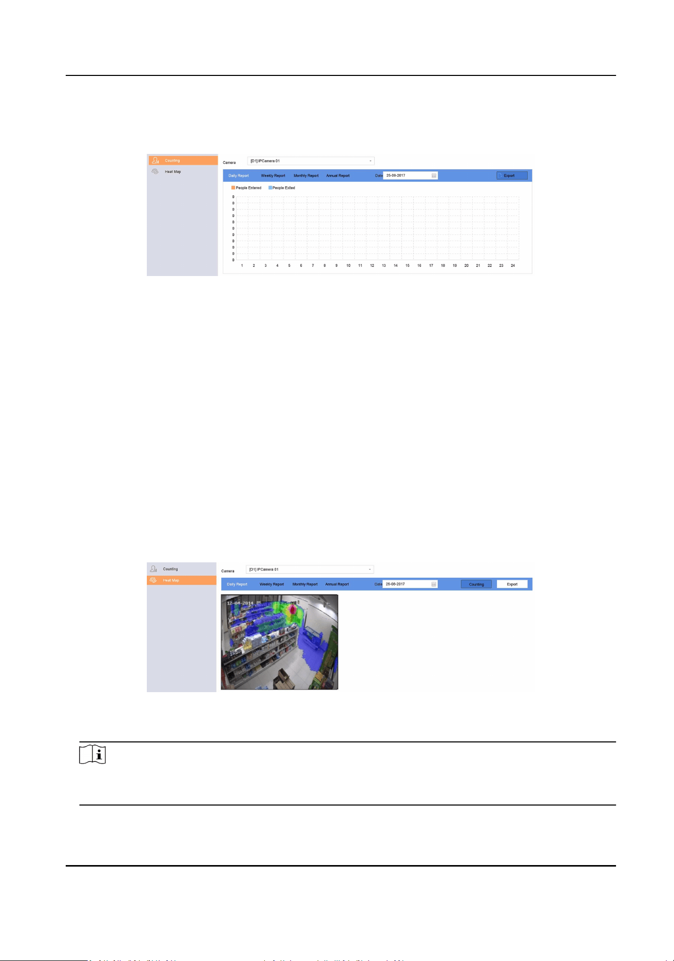
2. Select a camera.
3. Select the report type.
4. Set Date to analyze.
Figure 7-21 People Counng
5. Oponal: Click Export to export the report in Microso Excel format.
7.13 Heat Map
Heat map is a graphical representaon of data. The heat map funcon is used to analyze how
many people visited and stayed in a specic area.
Before You Start
The funcon must be supported by the connected IP camera and the corresponding parameters
must be set.
Steps
1. Go to Smart Analysis → Smart Report → Heat Map .
2. Select a camera.
3. Select the report type.
4. Set Date to analyze.
Figure 7-22 Heat Map
5. Click Counng.
Note
As shown in the gure above, red color block (255, 0, 0) indicates the most tracked area, and
blue color block (0, 0, 255) indicates the less-popular area.
Network Video Recorder User Manual
114

The results will be displayed in graphics marked in dierent colors.
6. Oponal: Click Export to export the stascs report in Microso Excel format.
Network Video Recorder User Manual
115
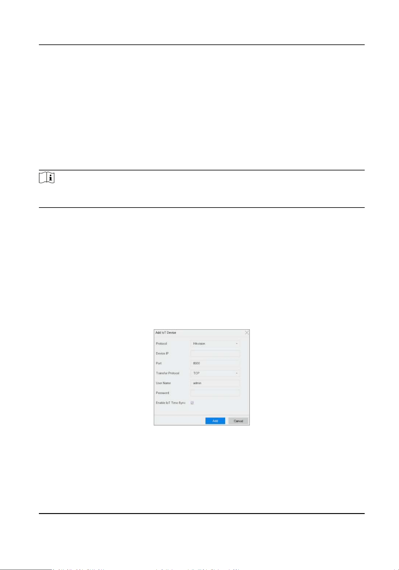
Chapter 8 IoT
IoT (Internet of Things) feature allows you to build connecons between your video recorder and
IoT devices, including access control and alarm devices. Video recorder will receive alarms from
connected IoT devices. You can congure linkage acons like triggering recording and full screen
monitoring, when IoT alarm occurs.
8.1 Add an IoT Device
Note
Maximum number of IoT channel is the half of maximum network camera number of your video
recorder.
8.1.1 Add an Access Control Device
Add Hikvision alarm host and video intercom devices to receive alarms. You can congure linkage
acons like triggering recording and full screen monitoring, when an alarm occurs.
Before You Start
Install access control devices. Ensure network communicaon between access control devices and
video recorder is well.
Steps
1. Go to Business Applicaon → IoT → Access Control → Device Management .
2. Click Add.
Figure 8-1 Access Control
3. Enter access control device informaon. Device IP, Port,Transfer Protocol, User Name, and
Password must be the same with access control device.
4. Oponal: Check Enable IoT Time Sync as your desire.
Network Video Recorder User Manual
116

Note
All IoT channels can be enabled/disabled with shortcuts.
a. Go to Maintenance → System Service → More Sengs .
b. Click Time Sync Conguraon, select Enable IoT Time Sync or Disable IoT Time Sync to
enable/disable scheduled me sync for all IoT channels.
Figure 8-2 IoT Time Sync
This funcon is only available for the admin user.
5. Click Add.
8.1.2 Add an Alarm Device
Add alarm devices of various manufacturers to receive alarms. You can congure linkage acons
like triggering recording and full screen monitoring, when an alarm occurs.
Before You Start
Install alarm devices. Ensure network communicaon between alarm devices and video recorder is
well.
Steps
1. Go to Business Applicaon → IoT → Alarm → Device Management .
2. Click Add.
Network Video Recorder User Manual
117
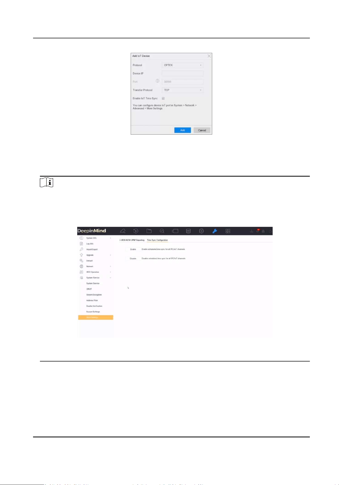
Figure 8-3 Alarm Device
3. Enter access control device informaon. The informaon must be the same with the alarm
device to add.
4. Oponal: Check Enable IoT Time Sync as your desire.
Note
All IoT channels can be enabled/disabled with shortcuts.
a. Go to Maintenance → System Service → More Sengs .
b. Click Time Sync Conguraon, select Enable IoT Time Sync or Disable IoT Time Sync to
enable/disable scheduled me sync for all IoT channels.
Figure 8-4 IoT Time Sync
This funcon is only available for the admin user.
5. Click Add.
Network Video Recorder User Manual
118

8.1.3 Add Network Audio Device
Network audio devices can also be added to your recorder, and the audios can be recorded. If a
network camera does not have a pick-up, or the recorded audio is not useful, an audio device can
be linked with the camera to replenish the audio eect.
Before You Start
Ensure the network audio device is properly connected.
Steps
1. Go to Business Applicaon → IoT → Audio → Device Management .
2. Click Add.
3. Set the device parameters, including IP address, password, etc.
Link Network Camera
You can link the audio device to a network camera. Aer the linkage succeeded, the audio of
network camera would be replaced with this audio device.
4. Click Add.
5. Oponal: Click to play the real-me audio.
6.
Oponal: Click
to edit device parameters.
7. Oponal: Click Delete to play the delete the device.
Note
If the network audio device has linked a network camera, aer the audio device is deleted, the
recorder will store audio of the linked network camera itself.
8.2 Congure the Linkage Acon and Arming Schedule
Congure the linkage acons and arming schedule for access control or alarm devices. Linkage
acons will be triggered when the designate alarm occurs.
Steps
1. Click of an added IoT device.
Network Video Recorder User Manual
119

Figure 8-5 Congure IoT
2. Select Event Type. The following conguraon is only valid for the selected event type.
3. Check Enable.
4. Check linkage acons as your desire. For detailed steps, refer to
Congure Linkage Acons .
Note
Full Screen Monitoring and OSD Display are only valid for the selected Trigger Channel.
5. Click Arming Schedule.
6. Congure arming schedule. For detailed steps, refer to Congure Arming Schedule . Linkage
acon is only valid during the set schedule.
7. Click Apply.
8.3 Congure OSD
You can display alarm informaon received from IoT devices on live view image.
Steps
1. Click
of an added IoT device.
2. Check OSD Display on Event Conguraon interface.
3. Select Trigger Channel.
4. Click OSD Display Conguraon.
Network Video Recorder User Manual
120

Figure 8-6 OSD Conguraon
5. Select items, including Device Name, Card No., Event Name, Name, and ID No., to display on
live view image. The items are only for access control devices.
6. Congure OSD properes.
Overlay Mode - Scroll
The OSD will automacally scroll to show the new alarm informaon.
Overlay Mode - Page
When the current OSD cannot show more alarm informaon, it will automacally turn to new
page.
Privacy Sengs
Enter privacy informaon you want to mask. Masked privacy informaon will be replaced by
*. Privacy informaon includes Event, Device, Card, Name, and ID.
7. Adjust the quadrilateral of yellow frame on the preview window to adjust IoT OSD size and
posion.
8. Click Apply.
8.4 Congure Audio Parameters
Aer an network audio device is added, you can congure its parameters, including output
volume, sampling rate, DNR (digital noise reducon) level, etc.
Before You Start
Ensure you an audio device is added to your recorder, and the network connecon is valid.
Steps
1. Go to Business Applicaon → IoT → Audio → Audio Parameters .
Network Video Recorder User Manual
121
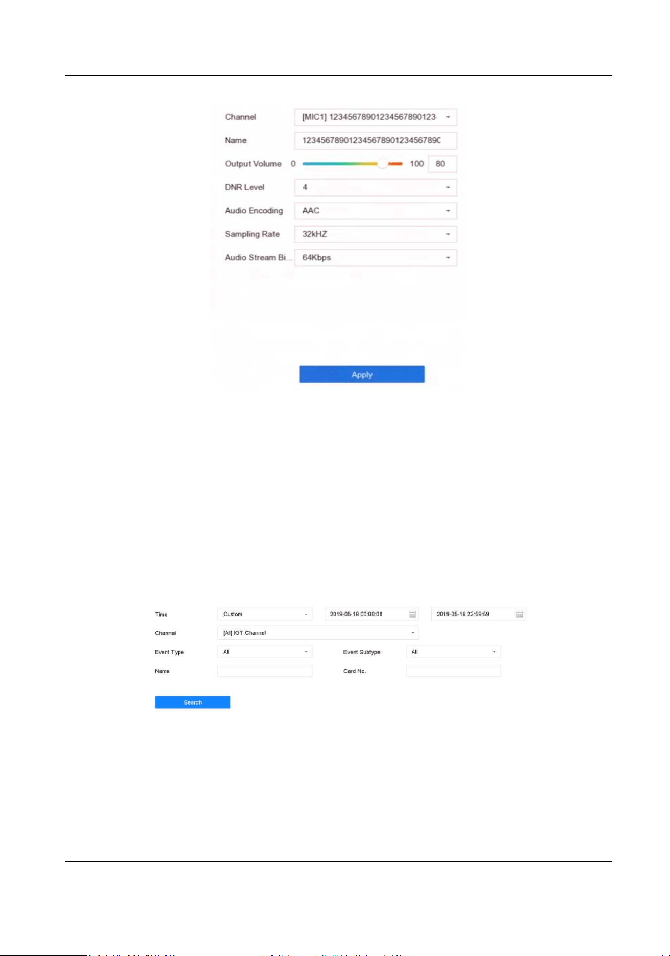
Figure 8-7 Congure Audio Parameters
2. Set the parameters as your desire.
3. Click Apply.
8.5 Search the IoT Record
Search alarms by me, by event type, or by channel.
Steps
1. Go to event record interface.
-
Access control: Go to Business Applicaon → IoT → Access Control → Card Swiping Record .
-
Alarm device: Go to Business Applicaon → IoT → Alarm → Search Data .
Figure 8-8 Search Event Record (Access Control)
Network Video Recorder User Manual
122
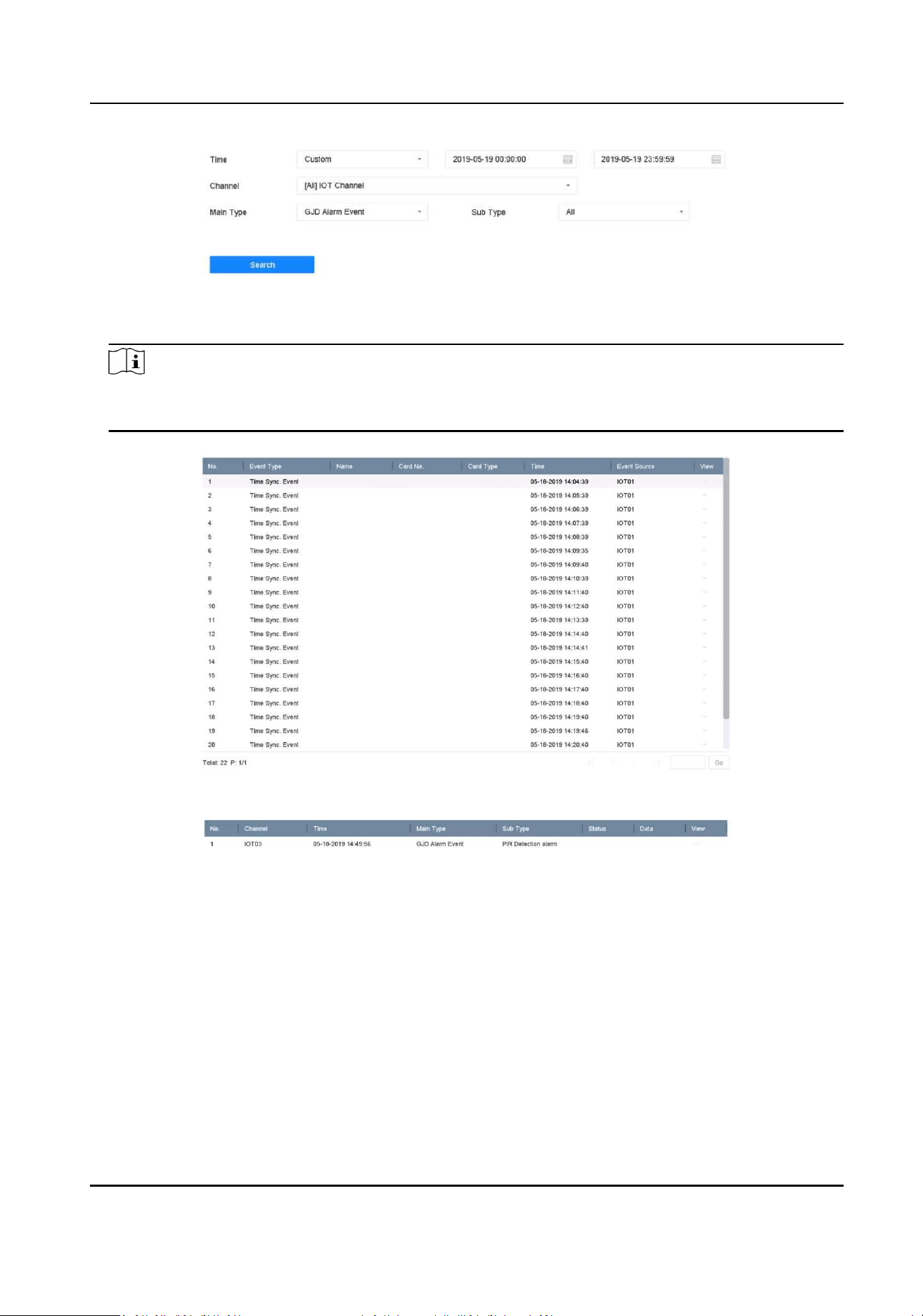
Figure 8-9 Search Event Record (Alarm Device)
2. Specify search condions.
Note
Name/Card No.: When card swiping event occurs, the access control device will upload card
name and card No. to video record. You can search event by card name or card No.
3. Click Search.
Figure 8-10 Search Result (Access Control)
Figure 8-11 Search Result (Alarm Device)
8.6 IoT Video/Picture
Congure the event recording or capturing schedule for the selected trigger channel, the channel
will automacally record videos or capture pictures when IoT alarm occurs.
Network Video Recorder User Manual
123
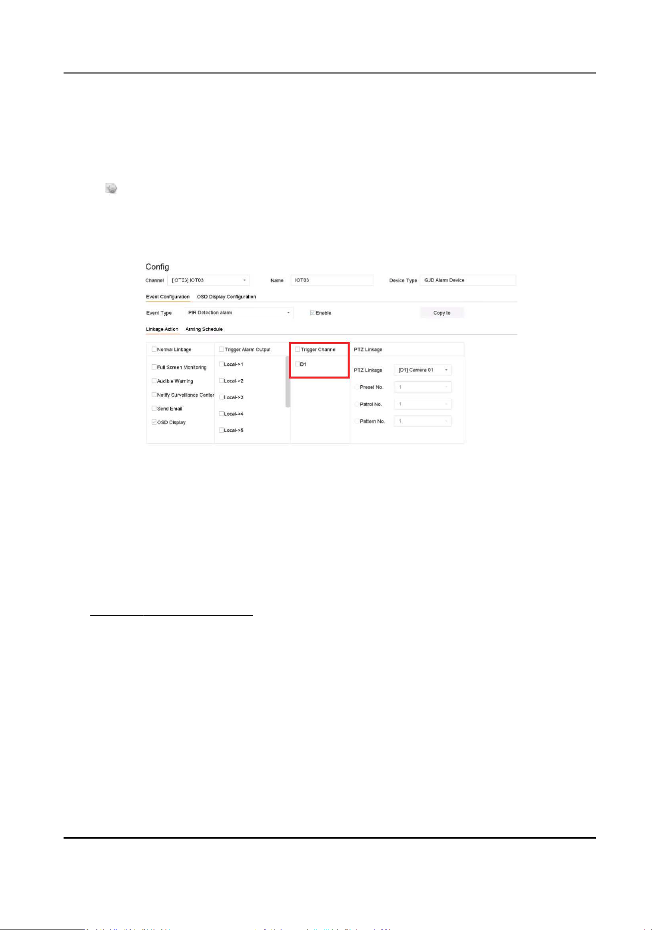
8.6.1 Congure the Event Recording/Capturing
The video recorder can record videos or capture pictures when an IoT alarm occurs.
Steps
1. Click of an added IoT device.
2. Select desired Event Type.
3. Check Enable.
4. Check Trigger Channel you want to record event videos or capture pictures when an alarm
occurs.
Figure 8-12 Trigger Channel
5. Click Apply.
6. Congure the event recording or capturing schedule. Here we take the example of conguring
event recording to describe the steps.
1) Go to Storage → Schedule → Record .
2) Select Camera No. and check Enable Schedule. The camera should be the camera you select
in step 4.
3) Select the recording type as Event.
4) Drag the mouse on the me bar to set the event detecon recording schedule. Refer to
Congure Recording Schedule for details.
5) Click OK.
Network Video Recorder User Manual
124
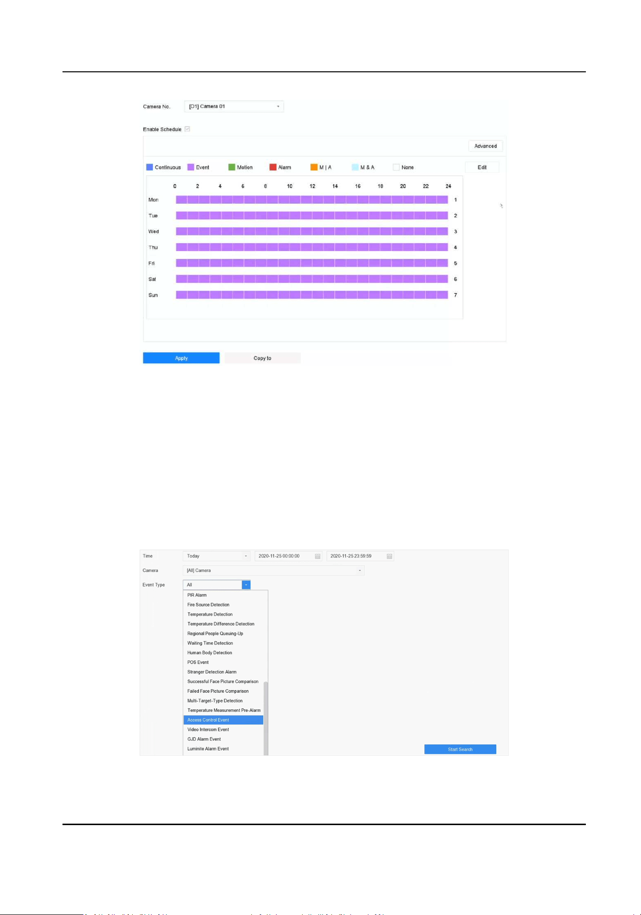
Figure 8-13 Event Recording
Result
When an alarm occurs, the selected trigger channel will start event recording.
8.6.2 Search IoT Video
Search IoT event triggered videos.
Steps
1. Go to File Management → Video → Search by Event .
Figure 8-14 Search Event Video
Network Video Recorder User Manual
125

2. Set search condions.
Camera
Select it as the selected trigger channels in IoT linkage acon conguraon.
Event Type
Select the desired IoT event.
3. Click Start Search.
Network Video Recorder User Manual
126

Chapter 9 File Management
9.1 Search Files
Specify detailed condions to search videos, audios and pictures.
Steps
1. Go to File Management → Video , File Management → Picture , or File Management → Audio
as your desire.
2. Select a search method. For example, Search by Appearance, or Search by Time.
3. Specify detailed condions, including me, camera, etc.
4. Click Start Search.
5. Click Channel to select a channel as your desire. It will display the searching results of the
selected channel.
6. Oponal: Click or to switch view mode.
7. Oponal: For videos, click or in dierent view mode to lock a video. The locked video will
not be overwrien.
8. Oponal: Export searching results.
1) Select result le(s) from the search result interface, or check Select All to select all les.
2) Click Export to export the selected le(s) to a backup device.
Note
●
You can click to view export progress.
●
You can click to return to search interface.
9.2 Export Files
Export les for backup purposes to a USB device, or eSATA HDD.
Steps
1. Search les. Refer to
Search Files for details.
2. Select les.
3. Click Export.
4. Oponal: For vehicle les, check Backup License Plate Stascs Info to export license plate
stascs informaon later.
5. Select the le to export as Video and log and click OK.
6. Select the backup device and folder path.
7. Click OK.
Network Video Recorder User Manual
127

9.3 Quick Backup
All the videos can be backed up with a shortcut.
Steps
1. Go to File Management → Video .
2. Search video(s) by seng dierent condions (appearance, event or tag).
3. Click Quick Backup.
Figure 9-1 Quick Backup
9.4 Smart Search
You can search human body les, face les and vehicles in File Management → Smart Search .
Refer to Human Body Search , Face Picture Search , and Vehicle Search for details.
Network Video Recorder User Manual
128

Chapter 10 Storage
10.1 Storage Device Management
10.1.1 SSD Management
Inialize SSD
For the device that has pre-installed SSD on the main board, you can view the SSD space
distribuon, or inialize the SSD.
Steps
1. Go to Storage → SSD Management .
2. Click Format.
3. Click Yes to inialize SSD.
Note
Inializing SSD will erase its data, including those in face picture library. The device will restart
aer inializaon.
4. Click Inialize Face Picture Library to delete face picture data in the SSD.
Note
The inializaon will make face picture library related alarms unavailable. The device will restart
aer inializaon.
SSD S.M.A.R.T. Detecon
Self-monitoring, analysis, and reporng technology (S.M.A.R.T.) is a monitoring system included in
computer hard disk drives (HDDs) and solid-state drives (SSDs) that detects and reports on various
indicators of drive reliability, with the intent of enabling the ancipaon of hardware failures. You
can run the S.M.A.R.T. detecon for your SSD.
Steps
1. Go to Maintenance → HDD Operaon → S.M.A.R.T
2. Set HDD No. as SSD.
3. Set Self-Test Type.
4. Click Self-Test to start the S.M.A.R.T. SSD self-evaluaon.
Network Video Recorder User Manual
129

Upgrade SSD Firmware
You can use a USB ash drive to upgrade your SSD rmware.
Before You Start
Prepare a USB ash drive that contains the SSD rmware, and insert the USB ash drive to your
device USB interface.
Steps
1. Go to Storage → SSD Management .
2. Click Firmware Upgrade.
3. Select Device Name as the USB ash drive that contains the SSD rmware.
4. Select the SSD rmware.
5. Click Upgrade.
10.1.2 Manage Local HDD
Congure HDD Group
Mulple HDDs can be managed in groups. Video from specied channels can be recorded onto a
parcular HDD group through HDD sengs.
Steps
1. Go to Storage → Storage Mode .
2. Select Mode as Group.
3. Click Apply.
4. Go to Storage → Storage Device .
5. Select a HDD.
Figure 10-1 Storage Device
6. Click to enter Local HDD Sengs interface.
Network Video Recorder User Manual
130
Figure 10-2 Local HDD Sengs
7. Select a group number for the HDD.
8. Click OK.
Note
Regroup the cameras for HDD if the HDD group number is changed.
9. Go to Storage → Storage Mode .
10. Select group number from the list.
11. Select related camera(s) to save videos and pictures on the HDD group.
12. Click Apply.
Congure the HDD Property
HDD property can be set as R/W, Read-only, or Redundant.
Before You Start
Set the storage mode to Group. For detailed steps, refer to Congure HDD Group
Steps
1. Go to Storage → Storage Device .
2. Click of desired HDD.
3. Select HDD Property.
Network Video Recorder User Manual
131

R/W
HDD supports both read and write.
Read-only
Files in read-only HDD will not be overwrien.
Redundant
Save the videos and pictures not only in the R/W HDD but also in the redundant HDD. It
eecvely enhances the data safety and reliability. Ensure at least another HDD which is in
Read/Write status exists.
4. Click OK.
Congure the HDD Quota
Each camera or audio device can be congured with an allocated quota for storing videos, pictures,
or audios.
Steps
1. Go to Storage → Storage Mode .
2. Select Mode as Quota.
3. Select a device type.
4. Select a device.
5. Set the storage capacity for the quota.
6. Click Copy to to copy the quota sengs of the current camera to other cameras.
7. Click Apply.
Note
●
When the maximum capacity is set to 0, devices will use the total HDD capacity for storing
les.
●
Reboot the video recorder to acvate the new sengs.
10.1.3 Add a Network Disk
You can add the allocated NAS or IP SAN disk to the device, and use it as a network HDD.
Steps
1. Go to Storage → Storage Device .
2. Click Add.
Network Video Recorder User Manual
132
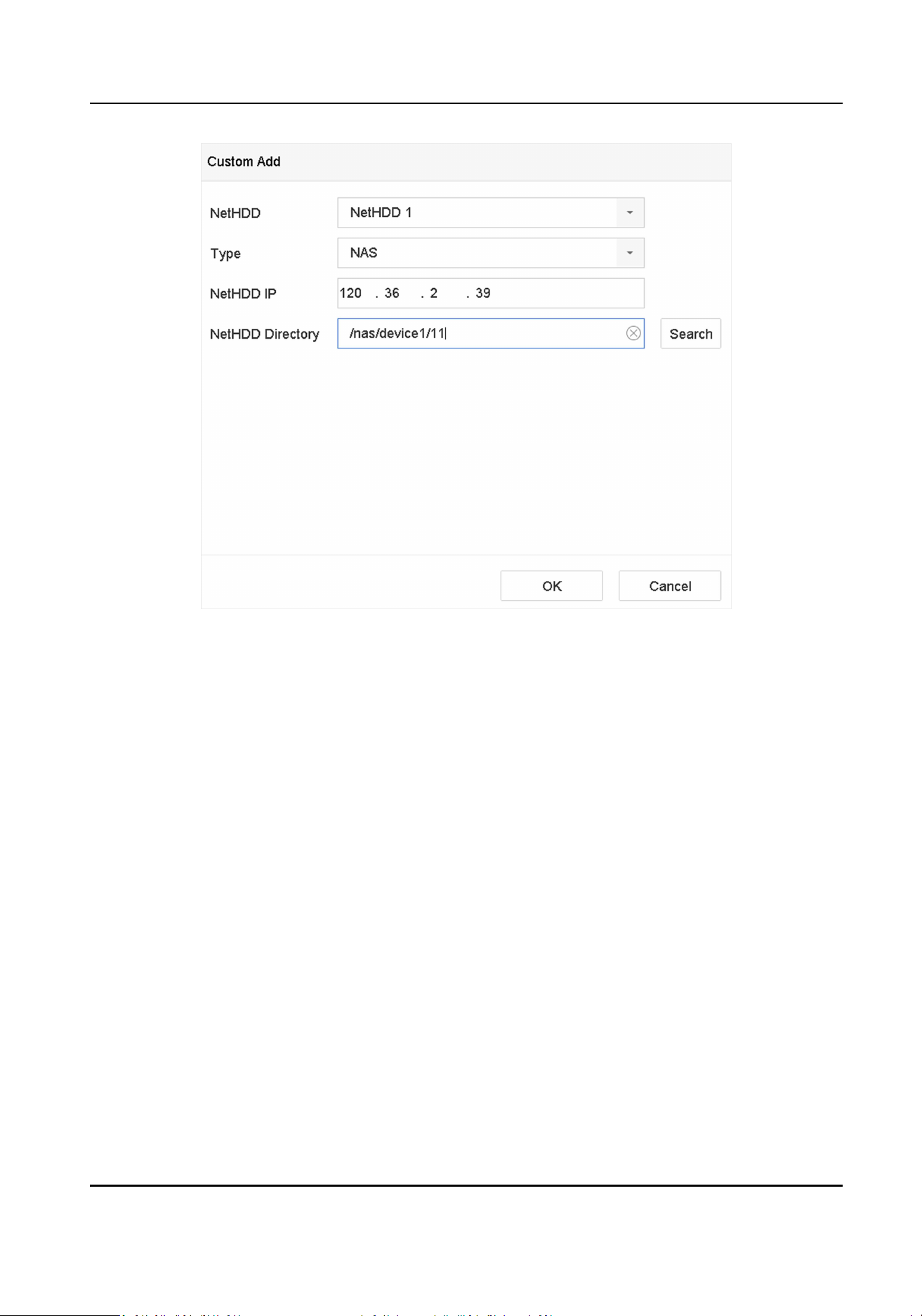
Figure 10-3 Add NetHDD
3. Select NetHDD type.
4. Enter NetHDD IP address and click Search to search the available NetHDD.
5. Select the desired NetHDD.
6. Click OK.
7. The added NetHDD will be displayed in the HDD list. Select the newly added NetHDD and click
Init.
10.1.4 Congure Cloud Storage
The cloud storage funcon enables the device to upload videos to a cloud server. It may not only
save your local HDD storage space, but also let you access videos more conveniently. You can
enable cloud storage via web browser.
Before You Start
Ensure your device is properly connected to Internet, and you have the correct cloud storage
informaon.
Steps
1. Go to Conguraon → Storage → Storage Management → Cloud Storage .
Network Video Recorder User Manual
133
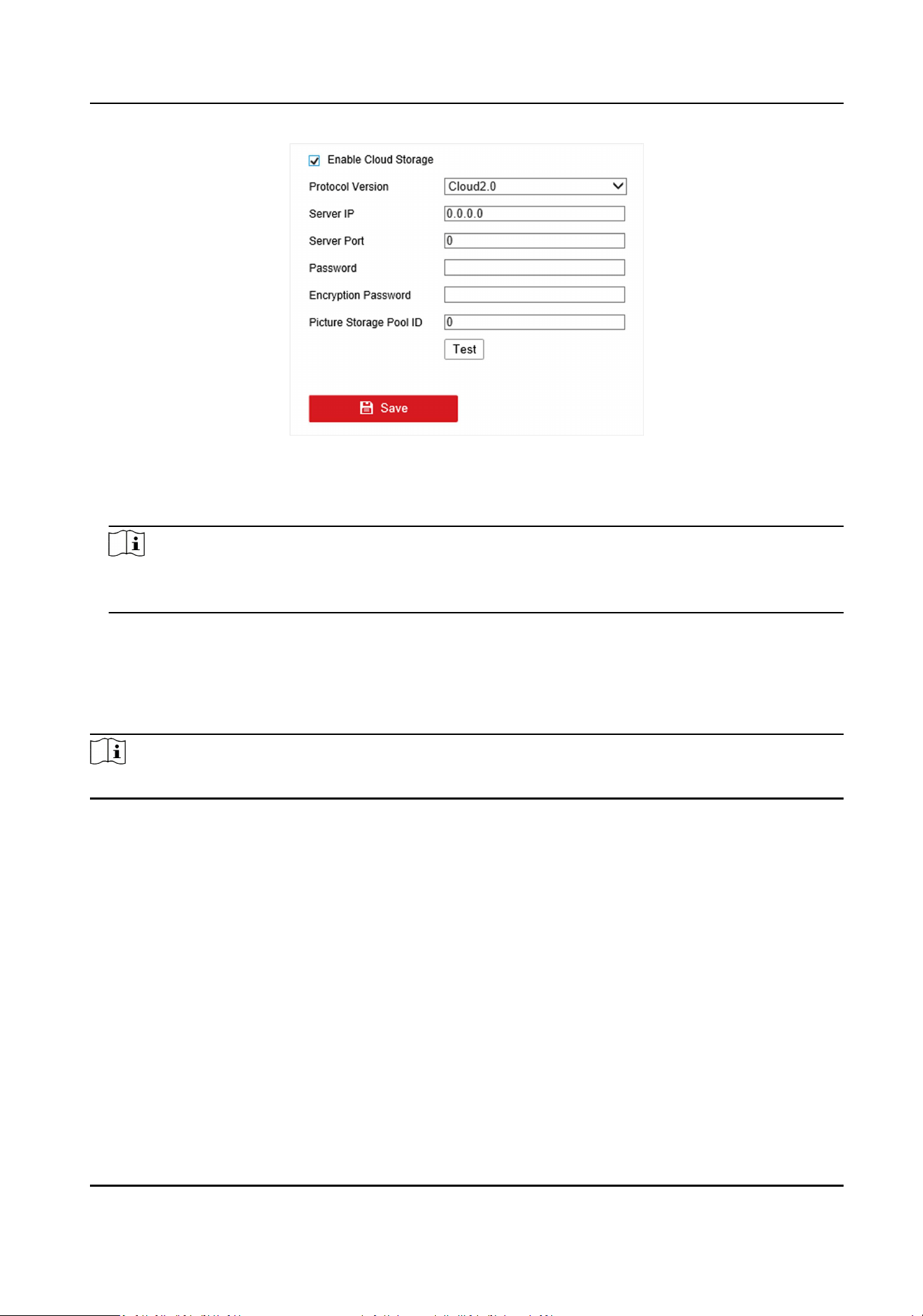
Figure 10-4 Cloud Storage
2. Check Enable Cloud Storage.
3. Set cloud storage server parameters.
Note
There are mulple pools in a cloud storage server. A pool is like an HDD, it is used for store les.
Each pool has an ID, hence you have to get the pool ID from storage server.
4. Click Test to test if parameters are valid.
5. Click Save.
10.1.5 Manage eSATA
Note
The eSATA funcon is only available for certain models.
Congure eSATA for Data Storage
When there is an external eSATA device connected to your video recorder, you can congure the
eSATA usage as data storage and manage the eSATA.
Steps
1. Go to Storage → Advanced .
2. Select eSATA Usage as Export or Record/Capture.
Export
Use the eSATA for backup.
Record/Capture
Use the eSATA for record/capture. Refer to the following steps for operang instrucons.
Network Video Recorder User Manual
134

Figure 10-5 eSATA Mode
What to do next
If eSATA usage is set as Record/Capture, enter the storage device interface to edit its property or
inialize it.
Congure eSATA for Auto Backup
If you made an automac backup plan, the video recorder will back up the local videos of 24 hours
ahead of the backup start me to eSATA.
Before You Start
Ensure the device has correctly connected with an external eSATA hard drive, and its usage type is
set as Export. Refer to Manage eSATA for details.
Steps
1. Go to Storage → Auto Backup .
2. Check Auto Backup.
3. Set the backup start me in Start Backup at.
Note
If the day experiences a failed backup, the video recorder will back up the videos 48 hours ahead
of the backup start me in the next day.
4. Select channels for backup.
5. Select Backup Stream Type as your desire.
6. Select Overwrite type.
-
Disable: When HDD is full, it will stop wring.
-
Enable: When HDD is full, it will connue to write new les by deleng the oldest les.
7. Click Apply.
Network Video Recorder User Manual
135
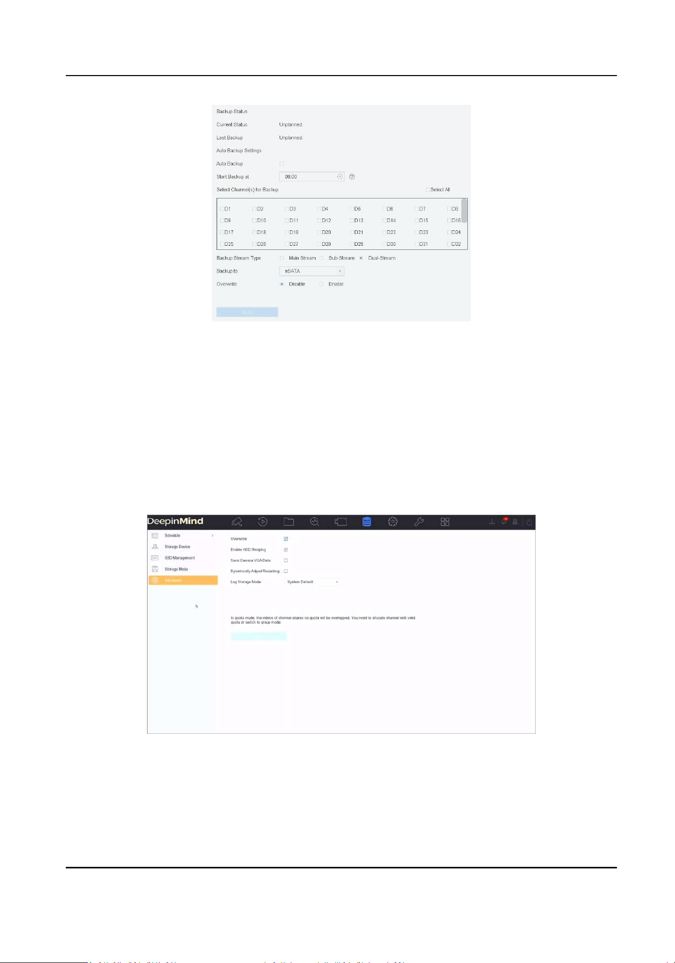
Figure 10-6 Congure eSATA for Auto Backup
10.1.6 Dynamically Adjust Recording Wring Buer
Dynamically adjust recording wring buer allows the device to adjust buer memory dynamically
when bit rate exceeds limit.
Steps
1. Go to Storage → Advanced .
2. Check Dynamically Adjust Recording Wring Buerto avoid video loss when bit rate is higher
than 4 Mbps.
Figure 10-7 Dynamically Adjust Recording Wring Buer
Network Video Recorder User Manual
136

Note
This funcon will result in higher memory use. Restart the device aer you enable/disable the
funcon.
10.2 Disk Array
A disk array is a data storage virtualizaon technology that combines mulple physical disk drives
into a single logical unit. Also known as a "RAID", an array stores data over mulple HDDs to
provide enough redundancy so that data can be recovered if one disk fails. Data is distributed
across the drives in one of several ways called "RAID levels", based the redundancy and
performance required.
Note
The funcons in this secon are only available for certain models.
10.2.1 Create a Disk Array
The video recorder supports soware-based disk arrays. Enable the RAID funcon as required, and
ensure each HDD capacity is not less than 4 TB. If your device has no more than 16 SATA interfaces,
a disk array can contain no more than 8 HDDs. If your device has 24 SATA interfaces, a disk array
can contain no more than 12 HDDs. Two ways are available for creang an array: one-touch
conguraon and manual conguraon.
One-Touch Creaon
One-touch conguraon creates the disk array. By default, the array type created by one-touch
conguraon is RAID 5.
Before You Start
Install at least 3 HDDs. If more than 10 HDDs are installed, 2 arrays will be created. To maintain
reliability and stability running of the HDDs, it is recommended to use of enterprise-level HDDs of
the same model and capacity.
Steps
1. Go to Storage → Advanced .
2. Check Enable RAID.
3. Click Apply and reboot the device to have sengs take eect.
4. Aer reboot, go to Storage → RAID Setup → Physical Disk .
5. Click One-touch Cong.
6. Edit Array Name and click OK to start conguring.
Network Video Recorder User Manual
137
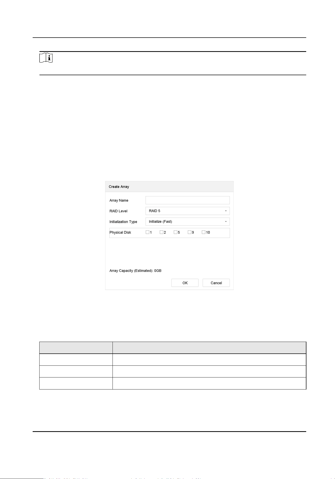
Note
If you install 4 or more HDDs, a hot spare disk for array rebuilding will be created.
7. Oponal: The video recorder will automacally inialize the created array. Go to Storage →
RAID Setup → Array to view the informaon of the created array.
Manual Creaon
Manually create a RAID 0, RAID 1, RAID 5, RAID 6, or RAID 10 array.
Steps
1. Go to Storage → Advanced .
2. Check Enable RAID.
3. Click Apply and reboot the device to have sengs take eect.
4. Aer reboot, go to Storage → RAID Setup → Physical Disk .
5. Click Create.
Figure 10-8 Create Array
6. Enter Array Name.
7. Select RAID Level as required.
8. Select the physical disks to constute the array.
Table 10-1 The Required Number of HDDs
RAID Level The Required Number of HDDs
RAID 0 At least 2 HDDs.
RAID 1 At least 2 HDDs.
RAID 5 At least 3 HDDs.
Network Video Recorder User Manual
138
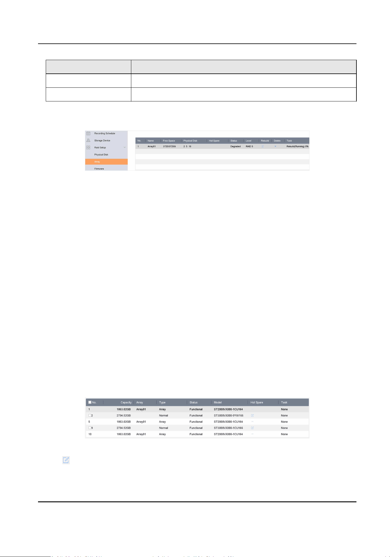
RAID Level The Required Number of HDDs
RAID 6 At least 4 HDDs.
RAID 10 The number of HDD must be an even ranges from 4 to 16.
9. Click OK.
10. Oponal: The video recorder will automacally inialize the created array. Go to Storage →
RAID Setup → Array to view the informaon of the created array.
Figure 10-9 Array List
10.2.2 Rebuild an Array
The array status includes Funconal, Degraded, and Oine. To ensure the high security and
reliability of the data stored in an array, take immediate and proper maintenance of the arrays
according its status.
Funconal
No disk loss in the array.
Oine
The number of lost disks has exceeded the limit.
Degraded
If any HDD fails in the array, the array degrades. Restore it to Funconal status by rebuilding the
array.
Congure a Hot Spare Disk
The hot spare disk is required for the disk array automac rebuilding.
Steps
1. Go to Storage → RAID Setup → Physical Disk .
Figure 10-10 Physical Disk
2. Click of an available HDD to set it as the hot spare disk.
Network Video Recorder User Manual
139

Automacally Rebuild an Array
The video recorder can automacally rebuild degraded arrays with the hot spare disks.
Before You Start
Create hot spare disks. For details, refer to Congure a Hot Spare Disk .
Steps
1. Go to Storage → RAID Setup → Array .
Figure 10-11 Array List
Manually Rebuild an Array
If no hot spare disks are congured, rebuild a degraded array manually.
Before You Start
At least one available physical disk must exist to rebuild an array.
Steps
1. Go to Storage → RAID Setup → Array .
2. Click of the degraded array.
Network Video Recorder User Manual
140
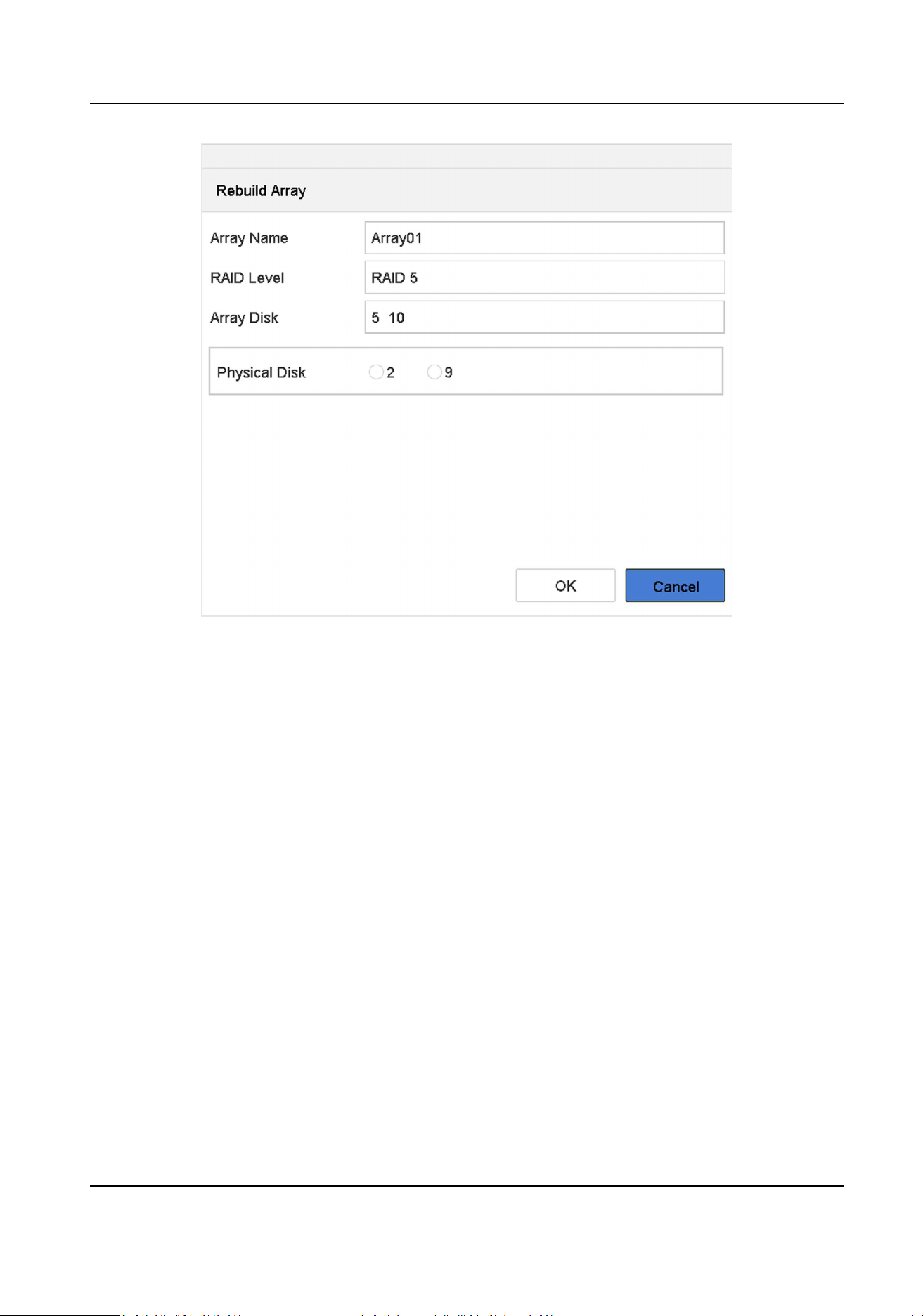
Figure 10-12 Rebuild Array
3. Select the available physical disk.
4. Click OK.
5. Click OK on the pop up message box "Do not unplug the physical disk when it is under
rebuilding."
Network Video Recorder User Manual
141
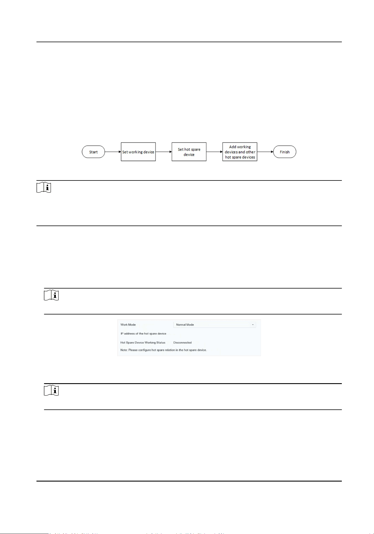
Chapter 11 Hot Spare Device Backup
Video recorders can form an N+M hot spare system. The system consists of several working video
recorders and at least one hot spare video recorder. When a working video recorder fails, the hot
spare video recorder would switch into operaon, which increases the reliability of the system.
A bidireconal connecon shown in the gure below is required to be built between hot spare
video recorder(s) and working video recorders.
Figure 11-1 Building a Hot Spare System
Note
●
Up to 32 working devices and 32 hot spare devices are allowed.
●
It is recommended to use all devices in a same model for compability. Contact your dealer for
details of models that support the hot spare funcon.
11.1 Set Working Device
Steps
1. Go to System → Hot Spare .
2. Set Work Mode as Normal Mode.
Note
Normal Mode is set by default.
Figure 11-2 Set Working Recorder
3. Click Apply.
Note
Repeat the above steps to set other working devices.
11.2 Set Hot Spare Device
Hot spare device will take over working device tasks when working device fails.
Network Video Recorder User Manual
142

Steps
1. Go to System → Hot Spare .
2. Set Work Mode as Hot Spare Mode.
Figure 11-3 Hot Spare
3. Click Apply.
4. Click Yes in the pop-up. Your device will restart automacally.
Note
●
The camera connecon will be disabled when the device works in hot spare mode.
●
It is highly recommended to restore the device defaults aer switching the work mode of hot
spare devices to normal mode to ensure the normal operaon aerward.
11.3 Manage Hot Spare System
Steps
Note
●
Up to 32 working devices and 32 hot spare devices are allowed in the hot spare system.
●
Only one hot spare device can add working devices and other hot spare devices. You can nd the
hot spare device IP address from working devices.
1. Go to System → Hot Spare through the hot spare device.
Figure 11-4 Add Working Device
2. Click Add in Working Device Sengs to add working devices to the hot spare system.
Aer refreshing the interface, you can view the working status of working devices from the hot
spare device interface. Also, the working status and IP address of the hot spare device can be
viewed from working device interface.
Network Video Recorder User Manual
143

Table 11-1 Working Status of Working Device
Working Status Descripon
Monitoring Working devices are working properly.
No need for backup The working device goes oine and has never
been monitored before.
Backing up The working device has been monitored
before but goes oine. A hot spare device will
take over the working device, and record the
videos of network cameras connected to the
working device. The video backup funcon can
be enabled for one working device at a me.
Waing for synchronizaon The working device comes back online, and
waits for the a hot spare device to sync videos.
Synchronizing The hot spare device is restoring videos back
into the working device. The synchronizaon
funcon can be enabled for one working
device at a me.
Synchronizaon nished Videos are restored back to the working
device. The work device is recovered.
3. Click Add in Hot Spare Device Sengs to add hot spare devices to the hot spare system.
4. Oponal: Click Delete to delete working devices or hot spare devices as your desire.
Network Video Recorder User Manual
144
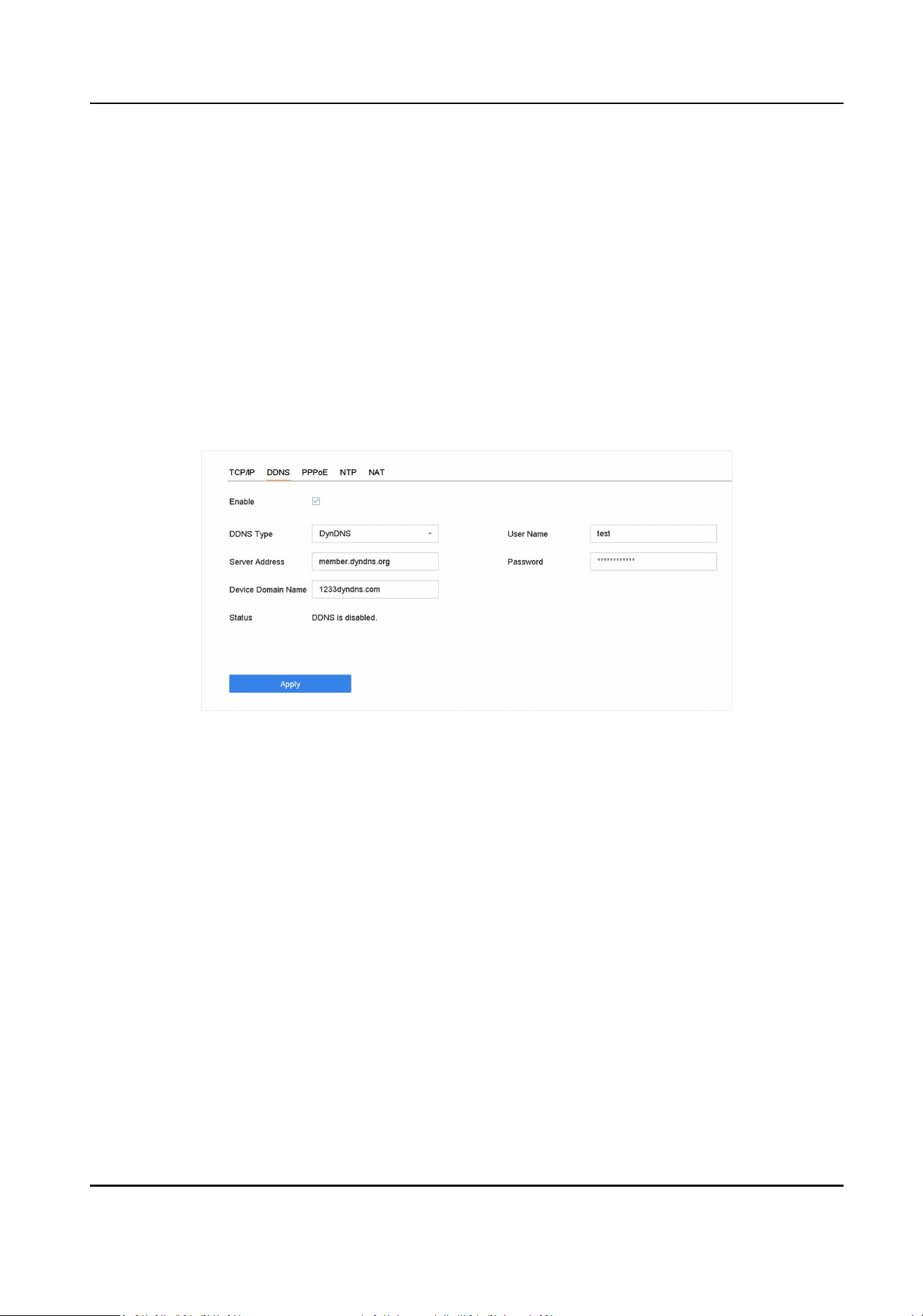
Chapter 12 Network Sengs
12.1 Congure DDNS
You can set Dynamic DNS service for network access. Dierent DDNS modes are available: DynDNS,
PeanutHull, and NO-IP.
Before You Start
You must register the DynDNS, PeanutHull, or NO-IP services with your ISP before conguring
DDNS sengs.
Steps
1. Go to System → Network → TCP/IP → DDNS
Figure 12-1 DDNS Sengs
2. Check Enable.
3. Select DDNS Type as DynDNS.
4. Enter Server Address for DynDNS (i.e., members.dyndns.org).
5. Under Device Domain Name, enter the domain name obtained from the DynDNS Website.
6. Enter User Name and Password registered in the DynDNS Website.
7. Click Apply.
12.2 Congure PPPoE
If the device is connected to Internet through PPPoE, you need to congure user name and
password accordingly under System → Network → TCP/IP → PPPoE .
Contact your Internet service provider for details about PPPoE service.
Network Video Recorder User Manual
145
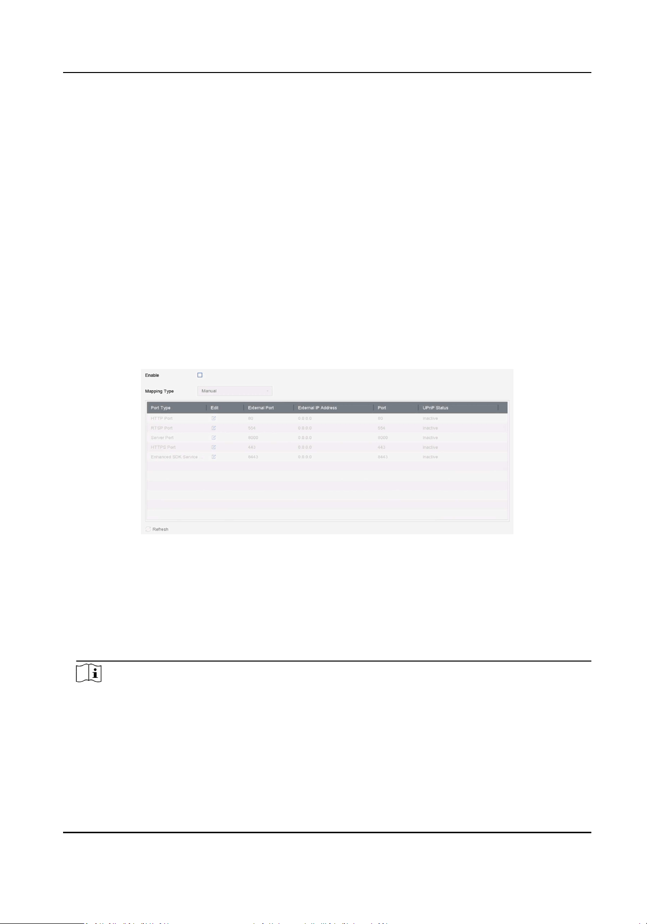
12.3 Congure Port Mapping (NAT)
Two ways are provided for port mapping to realize the remote access via the cross-segment
network, UPnP™ and manual mapping.
Before You Start
If you want to enable the UPnP™ funcon of the device, you must enable the UPnP™ funcon of
the router to which your device is connected. When the network working mode of the device is set
as mul-address, the Default Route of the device should be in the same network segment as that
of the LAN IP address of the router.
Universal Plug and Play (UPnP™) can permit the device seamlessly discover the presence of other
network devices on the network and establish funconal network services for data sharing,
communicaons, etc. You can use the UPnP™ funcon to enable the fast connecon of the device
to the WAN via a router without port mapping.
Steps
1. Go to System → Network → TCP/IP → NAT .
Figure 12-2 Port Mapping Seng
2. Check Enable.
3. Select Mapping Type as Manual or Auto.
-
Auto: If you select Auto, the port mapping items are read-only, and the external ports are set
by the router automacally.
-
Manual: If you select Manual, you can edit the external port on your demand by clicking to
acvate External Port Sengs.
Note
●
You can use the default port No., or change it according to actual requirements.
●
External Port indicates the port No. for port mapping in the router.
●
The value of the RTSP port No. should be 554 or between 1024 and 65535, while the value of
the other ports should be between 1 and 65535 and the value must be dierent from each
Network Video Recorder User Manual
146
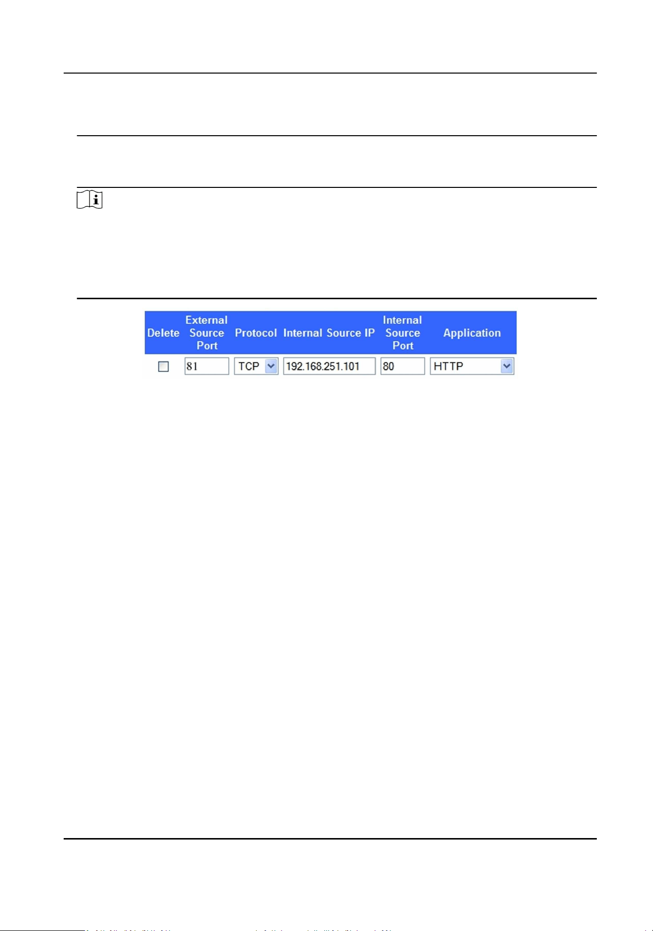
other. If mulple devices are congured for the UPnP™ sengs under the same router, the
value of the port No. for each device should be unique.
4. Enter the virtual server seng page of router; ll in the blank of Internal Source Port with the
internal port value, the blank of External Source Port with the external port value, and other
required contents.
Note
●
Each item should be corresponding with the device port, including server port, hp port, RTSP
port and hps port.
●
The virtual server seng interface below is for reference only, it may be dierent due to
dierent router manufactures. Please contact the manufacture of router if you have any
problems with seng virtual server.
Figure 12-3 Set Virtual Server Item
12.4 Congure SNMP
You can congure SNMP sengs to get device status and parameter informaon.
Before You Start
Download the SNMP soware to receive device informaon via the SNMP port. By seng the trap
address and port, the device is allowed to send alarm events and excepon messages to the
center.
Steps
1. Go to System → Network → Advanced → SNMP .
Network Video Recorder User Manual
147
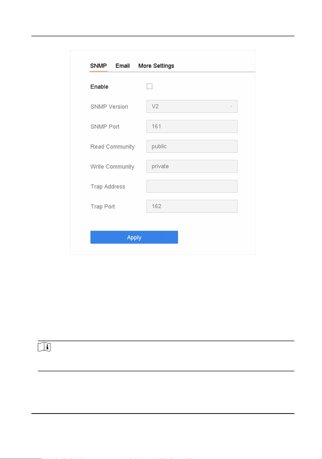
Figure 12-4 SNMP Sengs
2. Check Enable. A message will pop up to nofy about a possible security risk. Click Yes to
connue.
3. Congure the SNMP sengs as needed.
Trap Address
SNMP host IP address.
Trap Port
Port of the SNMP host.
4. Click Apply.
Note
You can congure SNMP v2 and SNMP v3 parameters via web browser in Conguraon →
System → Advanced Sengs → SNMP .
Network Video Recorder User Manual
148

12.5 Congure Email
The system can be congured to send an e-mail nocaon to all designated users when a
specied event occurs such as when an alarm or moon event is detected, or the administrator
password is changed, etc.
Before You Start
The device must be connected to a local area network (LAN) that contains an SMTP mail server.
The network must also be connected to either an intranet or the Internet depending on the
locaon of the email accounts to which you want to send nocaons.
Steps
1. Go to System → Network → Advanced → Email .
2. Congure the email sengs.
Server Authencaon
Check to enable the funcon if the SMTP server requires user authencaon and enter the
user name and password accordingly.
SMTP Server
The IP address of SMTP Server or host name (e.g., smtp.263xmail.com).
SMTP Port
The SMTP port. The default TCP/IP port used for SMTP is 25.
Enable SSL/TLS
Check to enable SSL/TLS if required by the SMTP server.
Sender
The sender's name.
Sender's Address
The sender's address.
Select Receivers
Select the receiver. Up to 3 receivers can be congured.
Receiver
The receiver's name.
Receiver's Address
The email address of the user to be noed.
Aached Image
Check to send email with aached alarm images. The interval is the me between sending
two subsequent alarm images.
Interval
The me interval for capturing the aached images.
Network Video Recorder User Manual
149
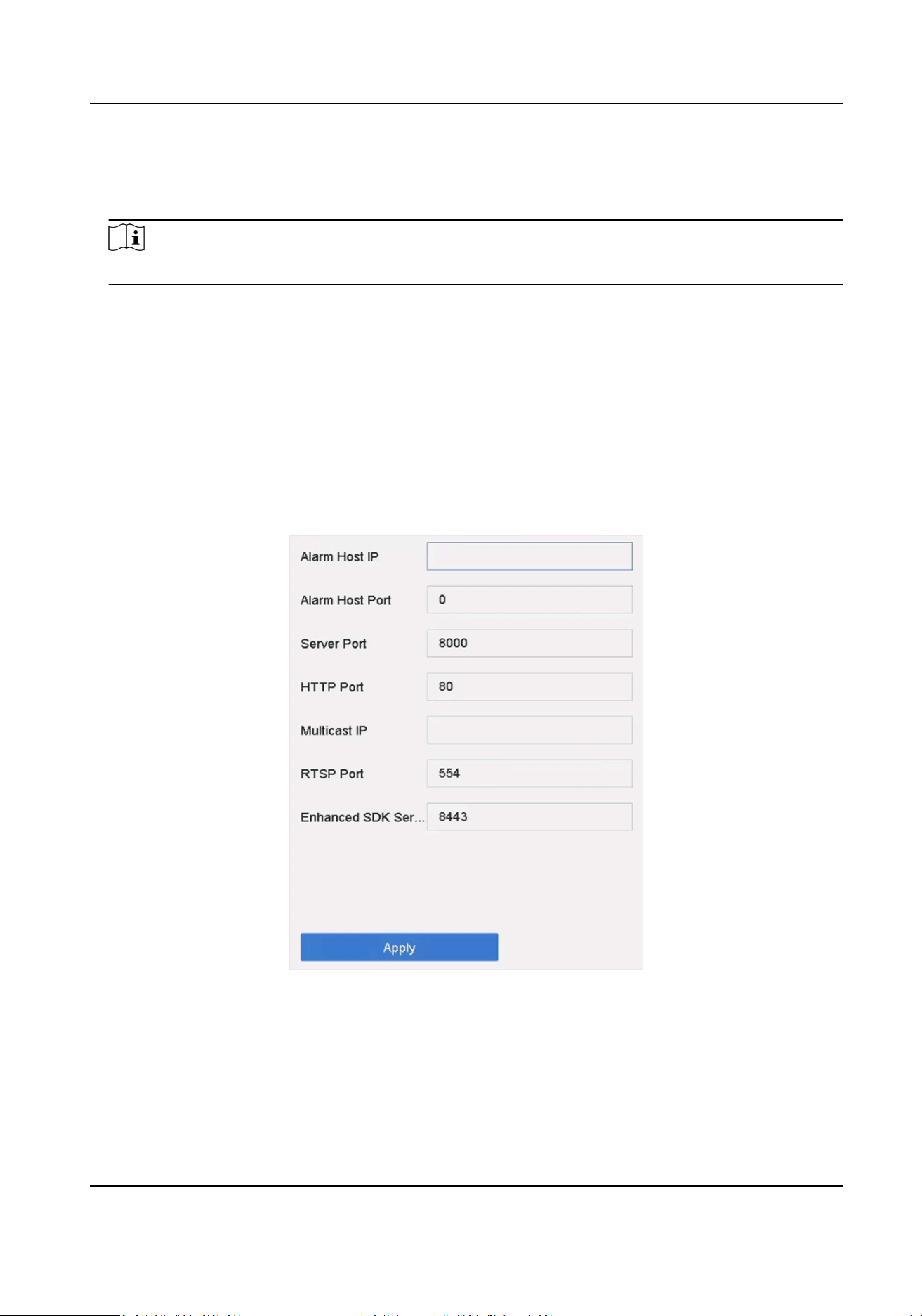
Perimeter Protecon Analysis and Capture by Device
When perimeter protecon events are analyzed by the device, the device will send you 3
images with target frames and rule frames in the alarm triggered email.
Note
Perimeter Protecon Analysis and Capture by Device is only available for /X and /S series.
3. Oponal: Enable the alternate SMTP, and congure the required parameters for alternate SMTP.
When the preferred SMTP is invalid, the device will use alternate SMTP to send emails.
4. Oponal: Click Test to send a test email.
5. Click Apply.
12.6 Congure Port
You can congure dierent types of ports to enable relevant funcons.
Steps
1. Go to System → Network → Advanced → More Sengs .
Figure 12-5 Port Sengs
2. Congure port sengs as needed.
Alarm Host IP/Port
With a remote alarm host congured, the device will send the alarm event or excepon
message to the host when an alarm is triggered. The remote alarm host must have the client
Network Video Recorder User Manual
150

management system (CMS) soware installed. The alarm host IP refers to the IP address of
the remote PC on which the CMS soware (e.g., iVMS-4200) is installed, and the alarm host
port (7200 by default) must be the same as the alarm monitoring port congured in the
soware.
Server Port
Server port (8000 by default) should be congured for remote client soware access and its
valid range is 2000 to 65535.
HTTP Port
HTTP port (80 by default) should be congured for remote Web browser access.
Mulcast IP
Mulcast can be congured to enable Live View for cameras that exceed the maximum
number allowed through network. Both IPv4 and IPv6 are available for mulcast IP address.
For IPv4, it covers Class-D IP ranging from 224.0.0.0 to 239.255.255.255 and it is
recommended to use an IP address ranging from 239.252.0.0 to 239.255.255.255. When
adding a device to the CMS soware, the mulcast address must be the same as that of the
device.
RTSP Port
RTSP (Real Time Streaming Protocol) is a network control protocol designed to control
streaming media servers. The port is 554 by default.
Enhanced SDK Service Port
The enhanced SDK service adopts TLS protocol over the SDK service that provides safer data
transmission. The port is 8443 by default.
3. Click Apply.
12.7 Congure ONVIF
ONVIF protocol allows the connecon with third-party cameras. The added user accounts have the
permission to connect other devices via ONVIF protocol.
Steps
1. Go to Maintenance → System Service → ONVIF .
2. Check Enable ONVIF to enable the ONVIF access management.
Note
ONVIF protocol is disabled by default.
3. Click Add.
4. Enter User Name, and Password
Network Video Recorder User Manual
151

Cauon
We highly recommend you create a strong password of your own choosing (Using a minimum of
8 characters, including at least three of the following categories: upper case leers, lower case
leers, numbers, and special characters.) in order to increase the security of your product. And
we recommend you reset your password regularly, especially in the high security system,
reseng the password monthly or weekly can beer protect your product.
5. Select Level as Media User, Operator or Admin.
6. Click OK.
Network Video Recorder User Manual
152

Chapter 13 POS Conguraon
The device can be connected to a POS machine/server, and receive a transacon message to
overlay on the image during Live View or playback, as well as trigger a POS event alarm.
13.1 Congure POS Connecon
Steps
1. Go to System → POS .
2. Click Add.
Figure 13-1 POS Sengs
3. Select a POS device from the drop-down list.
4. Check Enable.
Note
The number of POS devices supported by each device is the half of its number of channel, e.g., 8
POS devices are supported for the DS-9616NI-I8 model.
5. Select POS Protocol.
Note
When a new protocol is selected, reboot the device to acvate the new sengs.
Universal Protocol
Click Advanced to expand more sengs when selecng the universal protocol. You can set
the start line idener, line break tag, and end line tag for the POS overlay characters, and
the case-sensive property of the characters. You can also oponally check the ltering
idener and the XML protocol.
Network Video Recorder User Manual
153
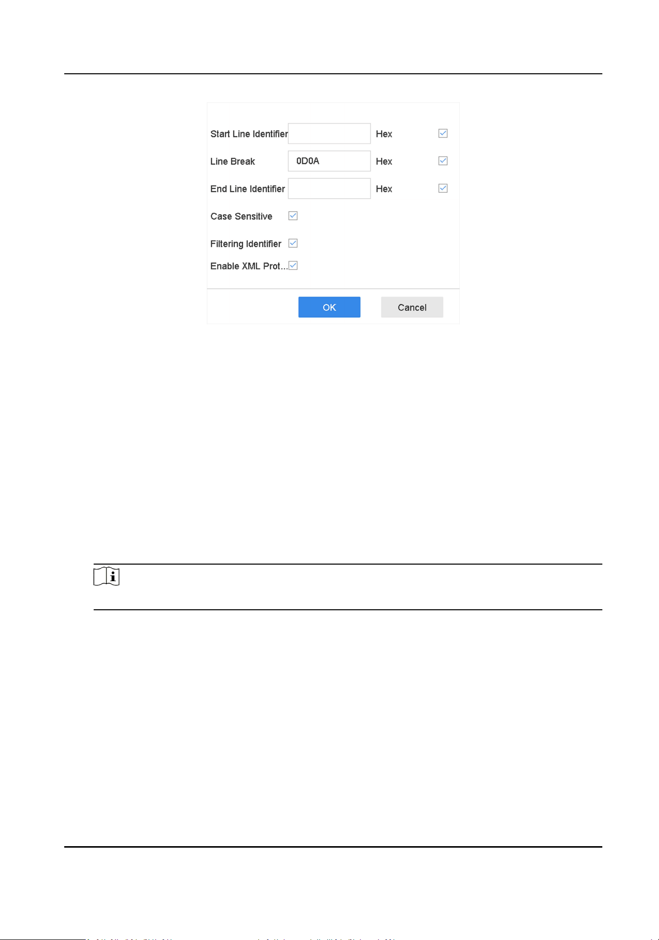
Figure 13-2 Universal Protocol Sengs
EPSON
The xed start and end line tag are used for EPSON protocol.
AVE
The xed start and end line tag are used for AVE protocol. Serial port and virtual serial port
connecon types are supported.
Click Custom to congure the AVE sengs. Select Rule as VSI-ADD or VNET . Set the address
bit of the POS message to send. Click OK to save the sengs.
NUCLEUS
Click the Custom to congure the NUCLEUS sengs.
Enter the employee No., shi No., and the terminal No. in the eld. The matching message
sent from the POS device will be used as the valid POS data.
Note
The NUCLEUS protocol must be used in the RS-232 connecon communicaon.
6. Select Connecon Mode and click Parameters to congure the parameters for each connecon
mode.
TCP Connecon
When using TCP connecon, the port must be set from 1 to 65535, and the port for each POS
machine must be unique.
Set the Allowed Remote IP Address of the device sending the POS message.
UDP Connecon
When using UDP connecon, the port must be set from 1 to 65535, and the port for each
POS machine must be unique.
Set the Allowed Remote IP Address of the device sending the POS message.
Network Video Recorder User Manual
154
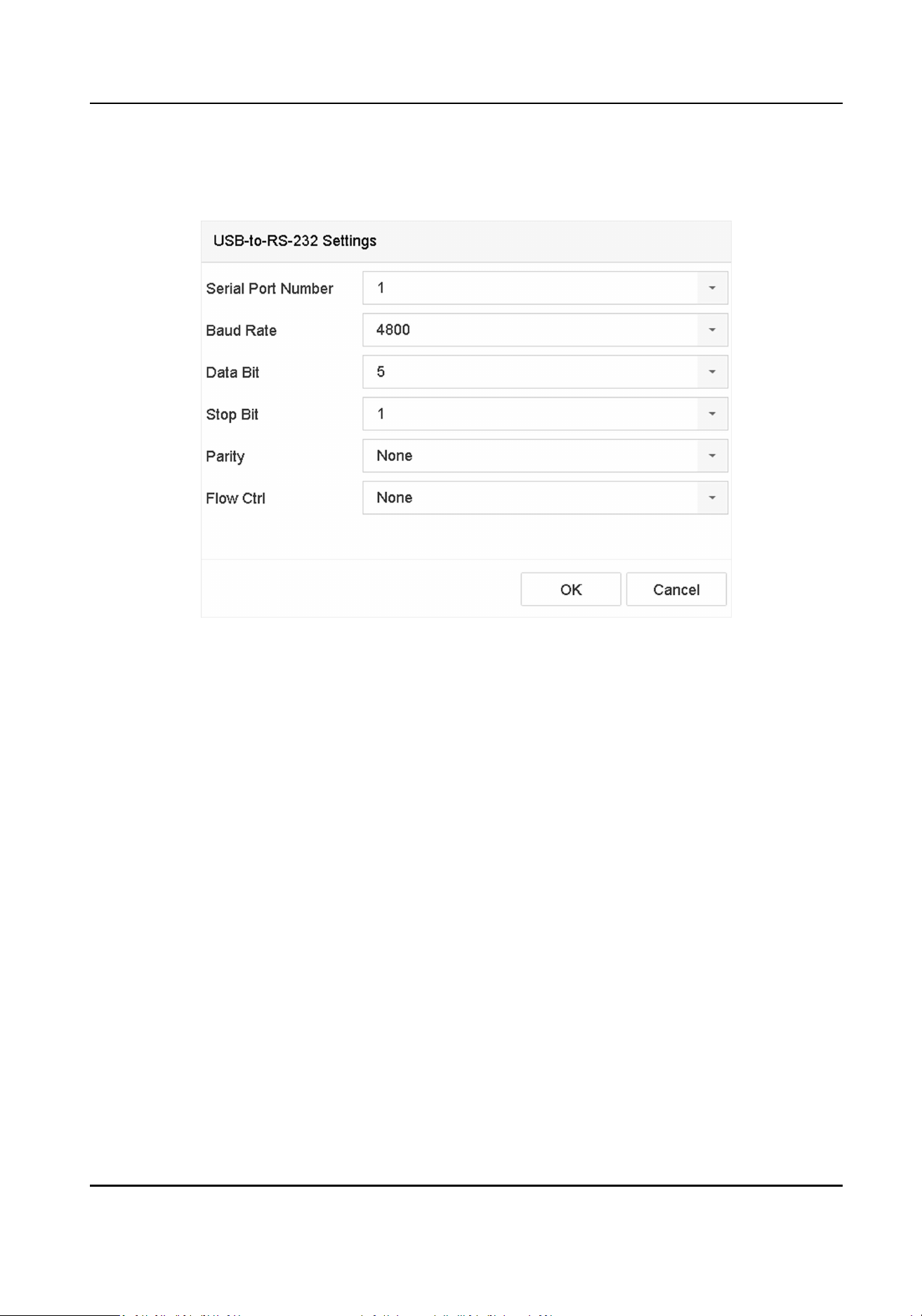
USB-to-RS-232 Connecon
Congure the USB-to-RS-232 convertor port parameters, including the port serial number,
baud rate, data bit, stop bit, parity, and ow ctrl.
Figure 13-3 USB-to-RS-232 Sengs
RS-232 Connecon
Connect the device and the POS machine via RS-232. The RS-232 sengs can be congured in
Menu → Conguraon → RS-232 . The Usage must be set to Transparent Channel.
Mulcast Connecon
When connecng the device and the POS machine via Mulcast protocol, set the mulcast
address and port.
Sni Connecon
Connect the device and the POS machine via Sni. Congure the source address and
desnaon address sengs.
Network Video Recorder User Manual
155
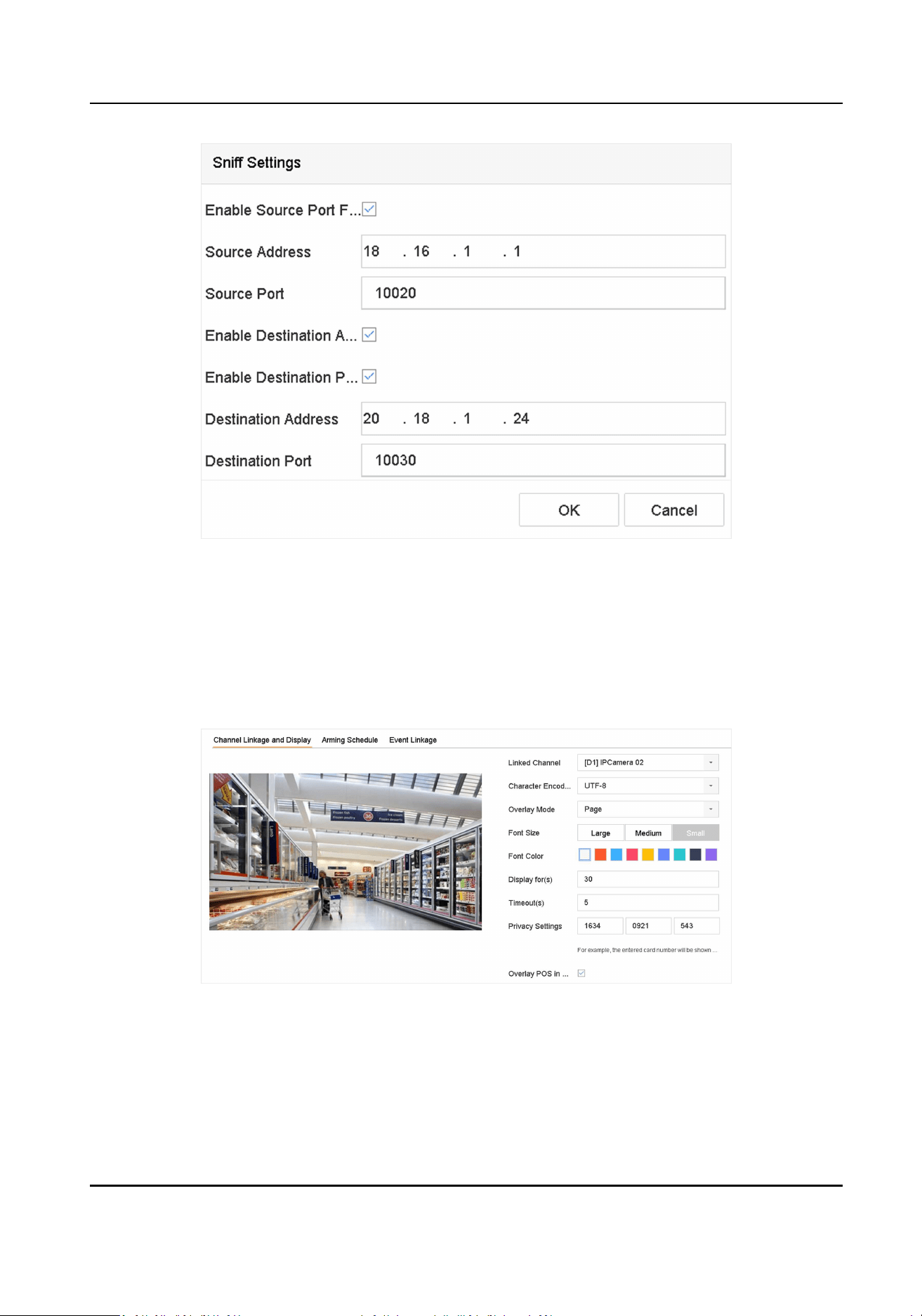
Figure 13-4 Sni Sengs
13.2 Congure POS Text Overlay
Steps
1. Go to System → POS .
2. Click Channel Linkage and Display.
Figure 13-5 Overlay Character Sengs
3. Select linked channel to overlay the POS characters.
4. Set the characters overlay for the enabled POS.
●
Character encoding format: currently the Lan-1 format is available
●
Overlay mode of the characters to display in scrolling or page mod
Network Video Recorder User Manual
156

●
Font size and font color
●
Display me (sec) of the characters. The value ranges 5 -3600 sec.
●
Timeout of POS event. The value ranges 5 -3600 sec. When the device has not received the
POS message within the dened me, the transacon ends.
5. In Privacy Sengs, set the POS privacy informaon to not display on the image, e.g., the card
number, user name, etc.
The dened privacy informaon will be displayed using ***on the image instead.
6. Check Overlay POS in Live View. When this feature is enabled, the POS informaon is overlaid
on the Live View image.
Note
Drag the frame to adjust the textbox size and posion on POS sengs interface preview screen.
7. Click Apply to acvate the sengs.
13.3 Congure POS Alarm
A POS event can trigger channels to start recording, or trigger full screen monitoring, etc.
Steps
1. Go to Storage → Recording Schedule .
2. Set the arming schedule. Refer to Congure Arming Schedule .
3. Go to System → POS .
4. Click Event Linkage on the POS adding or eding interface.
Network Video Recorder User Manual
157
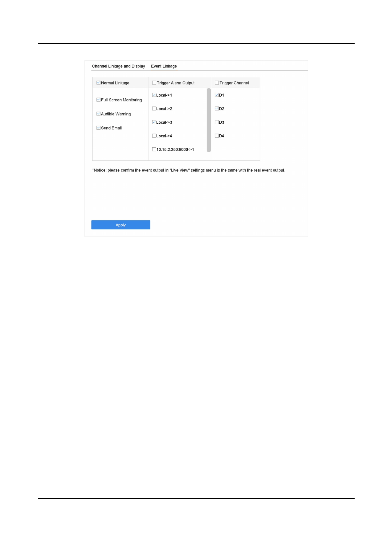
Figure 13-6 Set Trigger Cameras of POS
5. Select the normal linkage acons.
6. Select one or more alarm output(s) to trigger.
7. Select one or more channels to record or become full-screen monitoring when a POS alarm is
triggered.
8. Click Apply to save the sengs.
Network Video Recorder User Manual
158

Chapter 14 User Management and Security
14.1 Manage User Accounts
The Administrator user name is admin and the password is set when you start the device for the
rst me. The Administrator has the permission to add and delete users and congure user
parameters.
14.1.1 Add a User
Steps
1. Go to System → User .
2. Click Add to enter the operaon permission interface.
3. Input the admin password and click OK.
4. In the Add User interface, enter the informaon for a new user.
Cauon
Strong Password Recommended–We highly recommend you create a strong password of your
own choosing (using a minimum of 8 characters, including at least three of the following
categories: upper case leers, lower case leers, numbers, and special characters) in order to
increase the security of your product. We also recommend that you reset your password
regularly. Especially in the high security systems, reseng the password monthly or weekly can
beer protect your product.
User Level
Set the user level to Operator or Guest. Dierent user levels have dierent operang
permission.
●
Operator: An Operator user level has Two-way Audio permission in Remote Conguraon
and all operang permissions in Camera Conguraon by default.
●
Guest: The Guest user has no permission of Two-way Audio in Remote Conguraon and
only has the local/remote playback in the Camera Conguraon by default.
User’s MAC Address
The MAC address of the remote PC that logs onto the device. If it is congured and enabled,
it allows only the remote user with this MAC address to access the device.
5. Click OK.
In the User Management interface, the added new user is displayed on the list.
Network Video Recorder User Manual
159
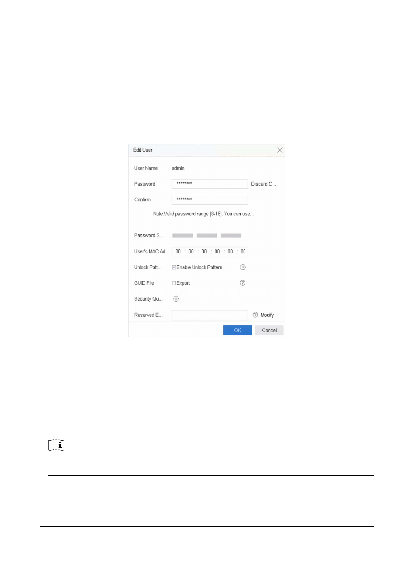
14.1.2 Edit the Admin User
For the admin user account, you can modify your password and unlock paern.
Steps
1. Go to System → User .
2. Select the admin user from the list.
3. Click Modify.
Figure 14-1 Edit User (Admin)
4. Edit the admin user informaon as desired, including a new admin password (strong password is
required) and MAC address.
5. Edit the unlock paern for the admin user account.
1) Check Enable Unlock Paern to enable the use of an unlock paern when logging in to the
device.
2) Use the mouse to draw a paern among the 9 dots on the screen, and release the mouse
when the paern is done.
6. Check Export of GUID File to export the GUID le for the admin user account.
Note
When the admin password is changed, export the new GUID to the connected USB ash drive in
the Import/Export interface for the future password reseng.
7. Congure security queson for password reseng.
8. Congure reserved email for password reseng.
Network Video Recorder User Manual
160
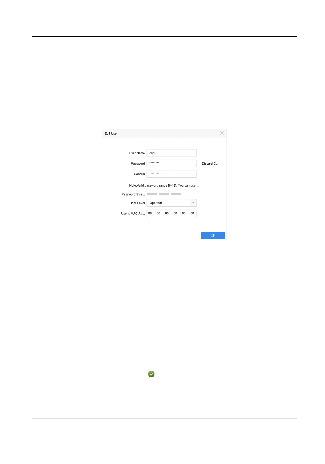
9. Click OK to save the sengs.
14.1.3 Edit an Operator/Guest User
You can edit the user informaon, including user name, password, permission level, and MAC
address.
Steps
1. Go to System → User .
2. Select a user from the list and click Modify.
Figure 14-2 Edit User (Operator/Guest)
3. Edit the user informaon as desired, including the new password (strong password is required)
and MAC address.
4. Click OK.
14.2 Manage User Permissions
14.2.1 Set User Permissions
For an added user, you can assign the dierent permissions, including local and remote operaon
of the device.
Steps
1. Go to System → User .
2. Select a user from the list, and then click to enter the permission sengs interface.
Network Video Recorder User Manual
161
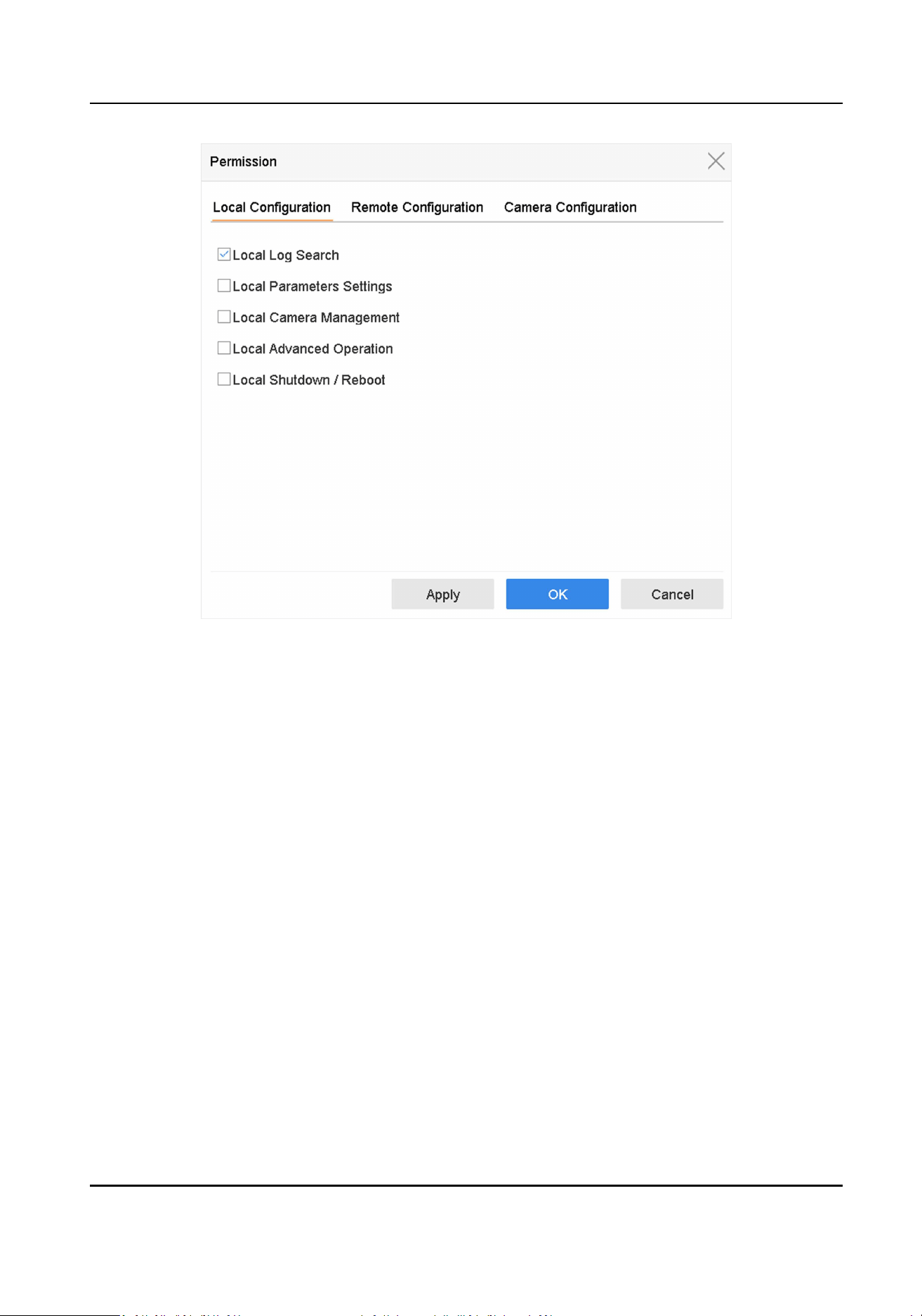
Figure 14-3 User Permission Sengs Interface
3. Set the user's operang permissions for Local Conguraon, Remote Conguraon, and
Camera Conguraon for the user.
1) Set Local Conguraon
Local Log Search
Searching and viewing logs and system informaon of device.
Local Parameters Sengs
Conguring parameters, restoring factory default parameters, and imporng/exporng
conguraon les.
Local Camera Management
Adding, deleng, and eding of IP cameras.
Local Advanced Operaon
Operang HDD management (inializing HDD, seng HDD property), upgrading system
rmware, clearing I/O alarm output.
Local Shutdown Reboot
Shung down or reboong the device.
2) Set Remote Conguraon
Remote Log Search
Network Video Recorder User Manual
162

Remotely viewing logs that are saved on the device.
Remote Parameters Sengs
Remotely conguring parameters, restoring factory default parameters, and imporng/
exporng conguraon les.
Remote Camera Management
Remote adding, deleng, and eding of the IP cameras.
Remote Serial Port Control
Conguring sengs for RS-232 and RS-485 port sengs.
Remote Video Output Control
Sending remote buon control signals.
Two-Way Audio
Operang the two-way radio between the remote client and the device.
Remote Alarm Control
Remotely arming (nofy alarm and excepon message to the remote client) and
controlling the alarm output.
Remote Advanced Operaon
Remotely operang HDD management (inializing HDD, seng HDD property), upgrading
system rmware, clearing I/O alarm output.
Remote Shutdown/Reboot
Remotely shung down or reboong the device.
3) Set Camera Conguraon
Remote Live View
Remotely viewing live video of the selected camera(s).
Local Manual Operaon
Locally starng/stopping manual recording and alarm output of the selected camera(s).
Remote Manual Operaon
Remotely starng/stopping manual recording and alarm output of the selected camera(s).
Local Playback
Locally playing back recorded les of the selected camera(s).
Remote Playback
Remotely playing back recorded les of the selected camera(s).
Local PTZ Control
Locally controlling PTZ movement of the selected camera(s).
Remote PTZ Control
Remotely controlling PTZ movement of the selected camera(s).
Network Video Recorder User Manual
163
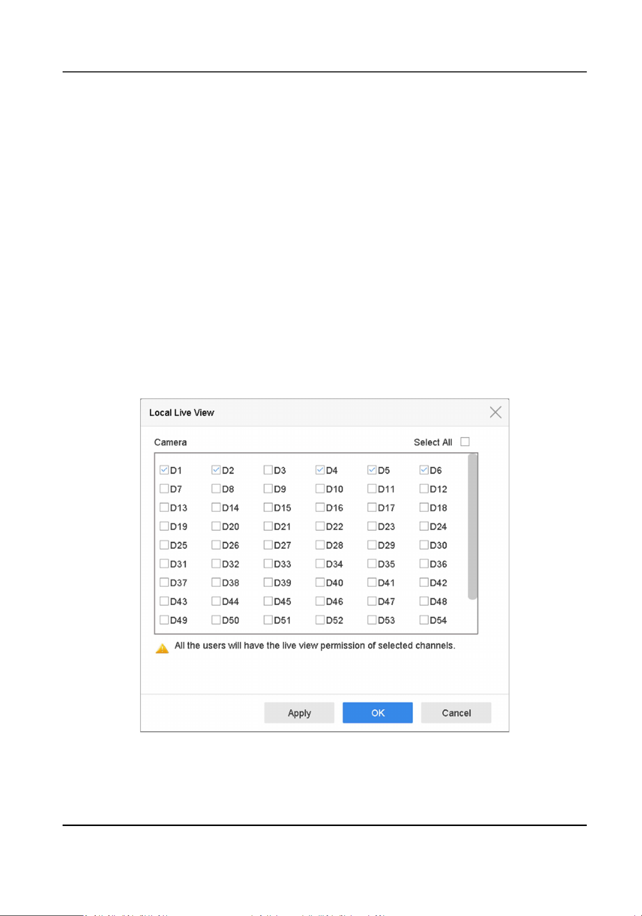
Local Video Export
Locally exporng recorded les of the selected camera(s).
Local Live View
View live video of the selected camera(s) in local.
4. Click OK to save the sengs.
14.2.2 Set Live View Permission on Lock Screen
The admin user can set live view permission for specic cameras in the screen lock status of device.
●
The admin user can set this permission for user accounts.
●
When the normal user (Operator or Guest) has no local live view permission for specic camera
(s), the live view permission for such camera (s) on lock screen status cannot be congured (live
view not allowed by default).
Steps
1. Go to System → User .
2. Click Live View Permission on Lock Screen.
3. Input admin password and click Next.
Figure 14-4 Set Live View Permissions on Lock Screen
Network Video Recorder User Manual
164
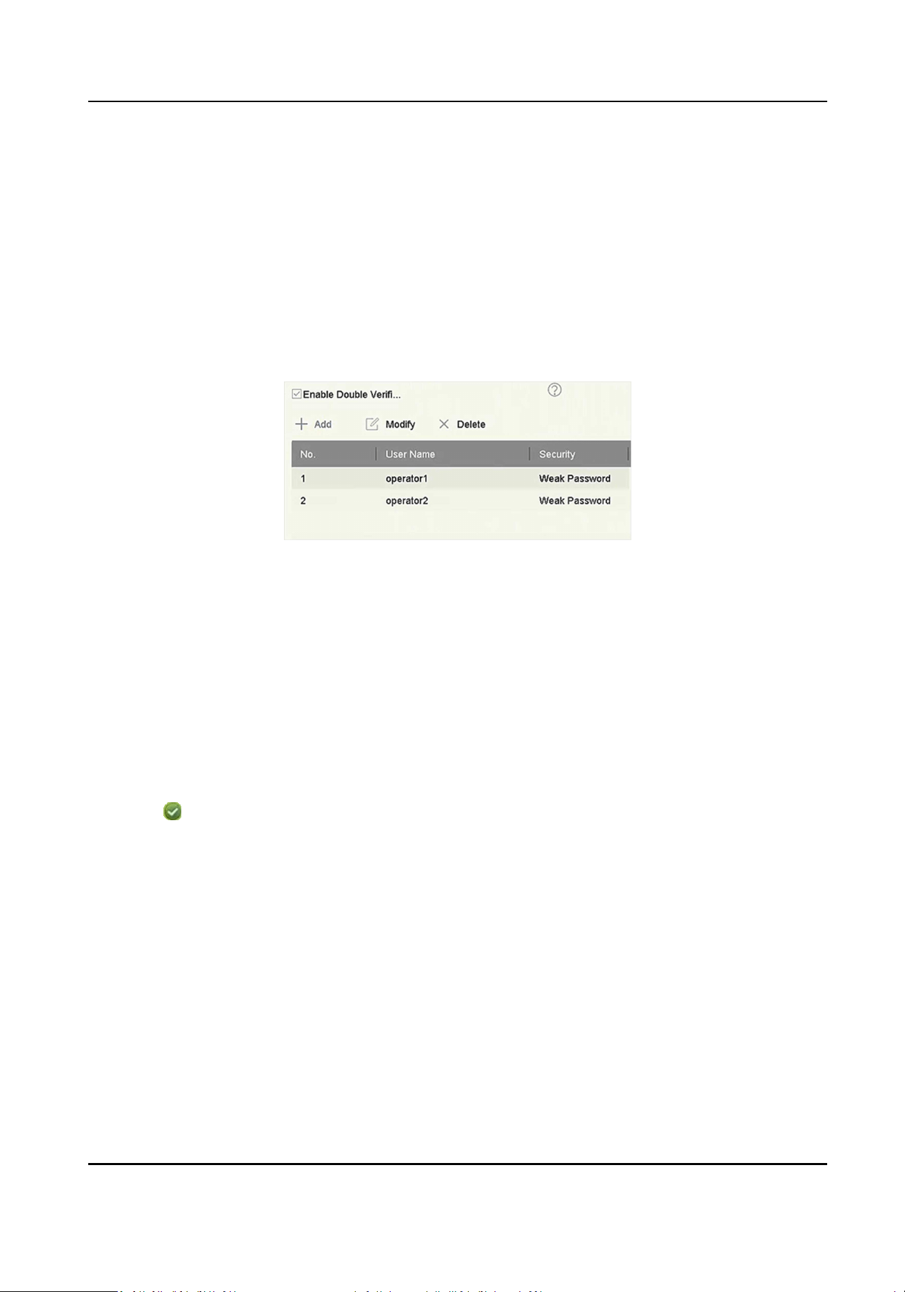
4. Set the permissions. Select the camera (s) to allow live view when the current user account is in
logout status.
5. Click OK.
14.2.3 Set Double Vericaon Permission for Non-admin Users
Aer double vericaon is enabled in the channel, a non-admin user must be veried by an
authorized user to get the permission. Only admin has the authorizaon to set double vericaon.
Steps
1. Go to Maintenance → System Service → Double Vericaon .
Figure 14-5 Set Double Vericaon User
2. Check Enable Double Vericaon.
3. Set double vericaon user. The double vericaon is dierent from the system user. You can
add up to 8 double vericaon users.
1) Click Add to add a double vericaon user.
2) Enter the admin password.
3) Set the user parameters, including user name, password, camera permission, etc.
4) Click OK.
4. Click Apply.
5. Set permission for non-admin users.
1) Go to System → User .
2) Click
to edit user permission.
3) Select Camera Permission. Only Local Playback, Remote Playback/Download, and Local
Video Export are available for double vericaon.
4) Select the channel(s) that requires double vericaon.
5) Click OK.
14.3 Congure Password Security
14.3.1 Export GUID File
The GUID le can help you to reset password when you forget it. You can export GUID le via web
browser. Please keep the GUID le properly.
Network Video Recorder User Manual
165
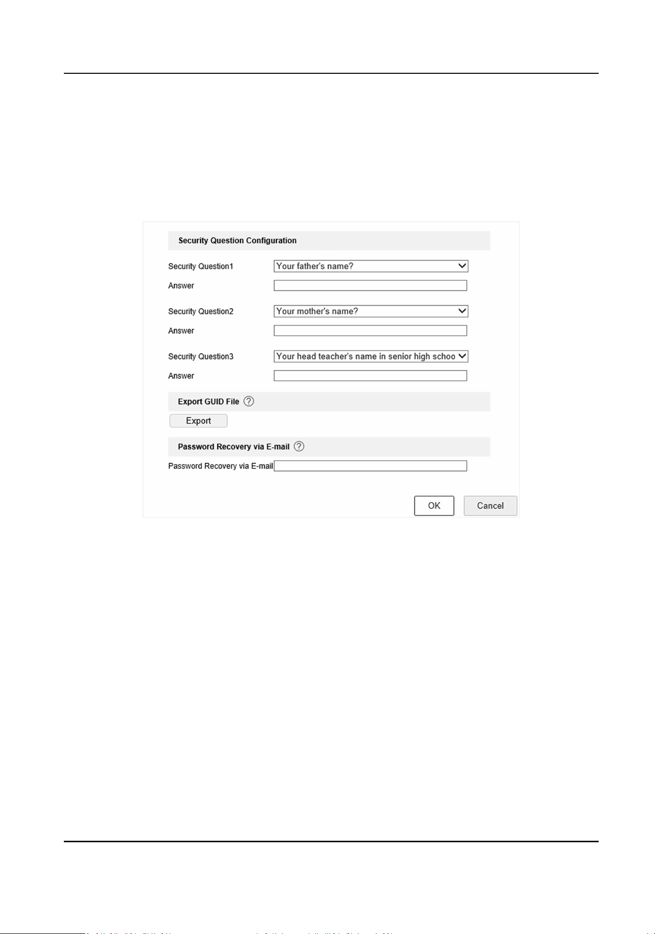
Before You Start
Ensure you are on the same network segment with your device.
Steps
1. Go to Conguraon → System → User Management → User Management .
2. Select the admin user.
3. Click Account Security Sengs.
4. Click Modify.
Figure 14-6 Export GUID File
5. Click Export in Export GUID File.
6. Enter the admin password.
7. Save the GUID le to a directory as your desire.
14.3.2 Congure Security Quesons
The security quesons can help you to reset password when you forget your password, or
encounter security issues.
Steps
1. Click Security Queson Conguraon when you are acvang the device, or eding the admin
user account.
2. Set the security quesons and answers.
Network Video Recorder User Manual
166
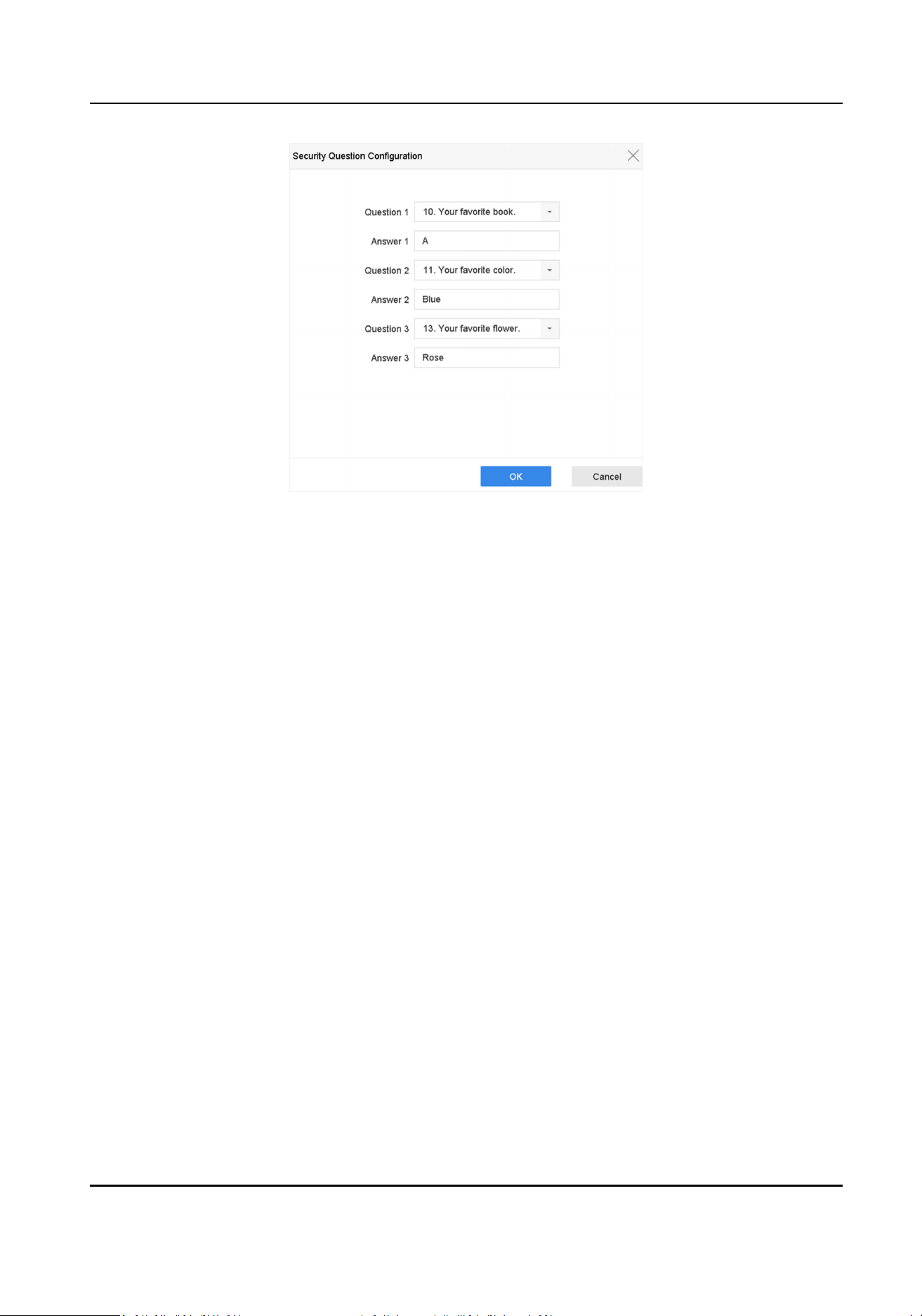
Figure 14-7 Congure Security Quesons
3. Click OK.
14.3.3 Congure Reserved Email
The reserved email will help you to reset password when you forget your password.
Steps
1. Check Reserved E-mail when you are acvang the device, or click Modify when you are eding
the admin user account.
2. Enter reserved email address.
Network Video Recorder User Manual
167
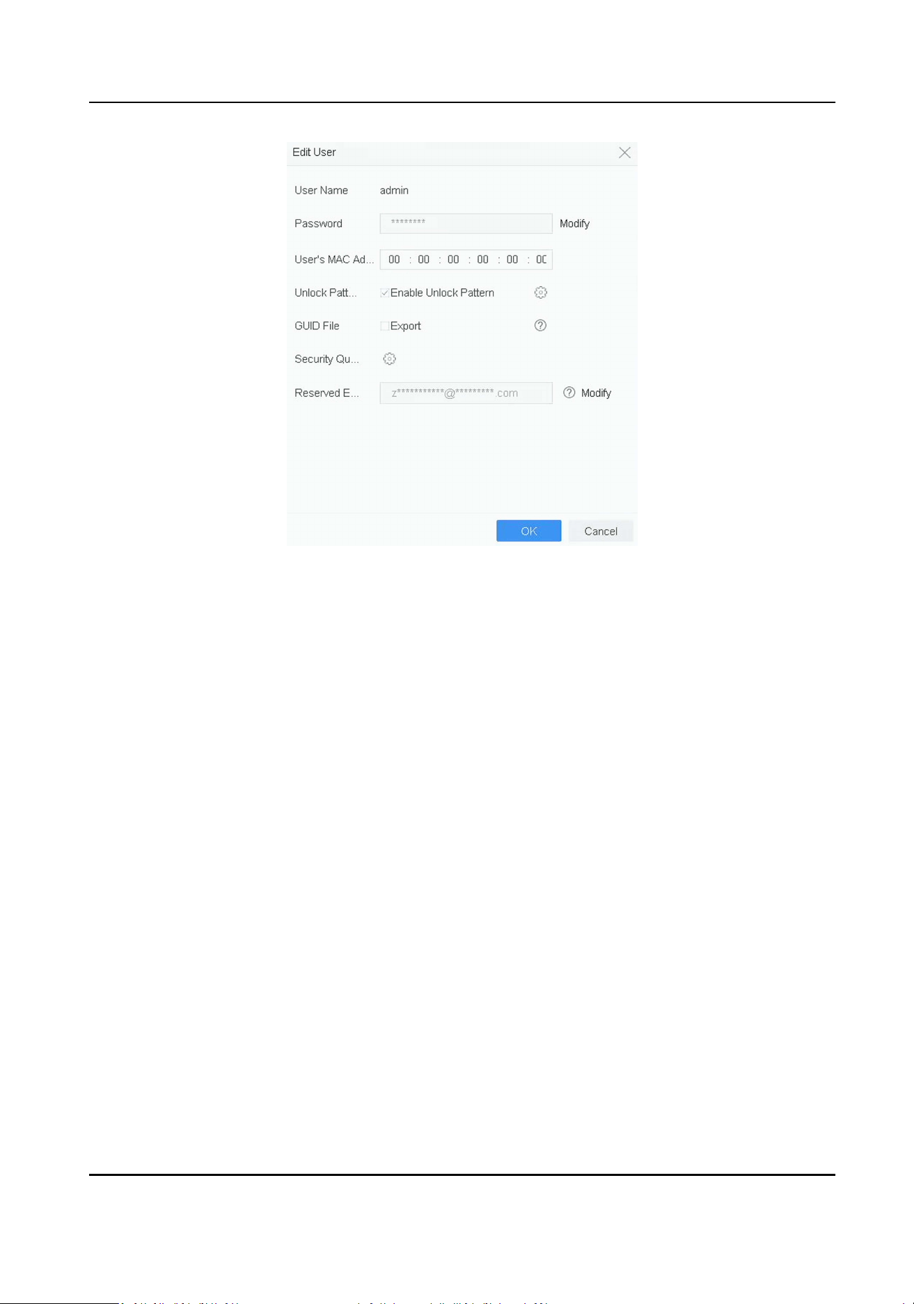
Figure 14-8 Congure Reserved Email
3. Click OK.
14.4 Reset Password
When you forget the admin password, you can reset the password by imporng the GUID le,
answering security quesons, or entering vericaon code from your reserved email.
14.4.1 Reset Password by GUID
You can reset password by GUID via web browser.
Before You Start
Ensure you have the correct GUID le.
Steps
1. On the user login interface, click Forgot password.
2. Select Vericaon Mode as GUID File Vericaon.
3. Click Browse to locate the GUID le.
4. Click Next.
5. Enter a new password.
Network Video Recorder User Manual
168

Warning
We highly recommend you to create a strong password of your own choosing (using a minimum
of 8 characters, including at least three kinds of following categories: upper case leers, lower
case leers, numbers, and special characters) in order to increase the security of your product.
And we recommend you change your password regularly, especially in the high security system,
changing the password monthly or weekly can beer protect your product.
6. Conrm the new password.
7. Click Next.
14.4.2 Reset Password by Security Quesons
Before You Start
You have congured the security quesons when you acvate the device or edit the admin user
account.
Steps
1. On the user login interface, click Forgot Password.
2. Select the password reseng type as Verify by Security Queson.
3. Input the correct answers of the three security quesons.
4. Click OK.
5. Create the new admin password on the Reset Password interface.
14.4.3 Reset Password by Reserved Email
Before You Start
Ensure you have congured the reserved email when you are acvang the device or eding the
admin user account. (Refer to Congure Reserved Email )
Steps
1. On the user login interface, click Forgot Password.
2. On the password reset type interface, select Verify by Reserved Email.
3. Click OK.
4. Click Next if you accept the legal disclaimer. You can use a smartphone to scan the QR code and
read the legal disclaimer.
5. Obtain the vericaon code. There are two ways to get the vericaon code.
-
Use Hik-Connect app to scan the QR code.
-
Send the QR code to email server.
a. Insert a USB ash drive to your device.
b. Click Export to export the QR code to USB ash drive.
c. Email the QR code to
[email protected] as aachment.
6. Check your reserved email, and you will receive a vericaon code within 5 minutes.
7. Enter the vericaon code.
Network Video Recorder User Manual
169

8. Click OK to set the new password.
14.4.4 Reset Password by Hik-Connect
It will restore all parameters to factory default sengs if you reset password by Hik-Connect.
Before You Start
Install the Hik-Connect app on your smart phone.
Steps
1. On the user login interface, click Forgot Password.
2. On the password reset type interface, select Verify by Hik-Connect.
3. Use Hik-Connect to scan the QR code. Thereaer, you will have a vericaon code from Hik-
Connect.
4. Enter the vericaon code.
5. Click OK.
Network Video Recorder User Manual
170

Chapter 15 System Management
15.1 Congure Device
Steps
1. Go to System → General .
2. Congure the following sengs.
Language
The default language used is English.
Output Standard
Set the output standard to NTSC or PAL, which must be the same as the video input standard.
Resoluon
Congure video output resoluon.
Device Name
Edit device name.
Device No.
Edit the device serial number. The Device No. can be set in the range of 1 to 255, and the
default No. is 255. The number is used for the remote and keyboard control.
Auto Logout
Set the meout me for menu inacvity. E.g., when the meout me is set to 5 minutes,
then the system will exit from the current operaon menu to Live View screen aer 5
minutes of menu inacvity.
Mouse Pointer Speed
Set the speed of the mouse pointer; 4 levels are congurable.
Enable Wizard
Enable/disable the Wizard when the device starts up.
Enable Password
Enable/disable the use of the login password.
3. Click Apply to save the sengs.
15.2 Congure Time
15.2.1 Manual Time Synchronizaon
Network Video Recorder User Manual
171

Steps
1. Go to System → General .
2. Congure the date and me.
3. Click Apply to save the sengs.
15.2.2 NTP Synchronizaon
Connecon to a network me protocol (NTP) server can be congured on your device to ensure
the system’s date and me accuracy.
Steps
1. Go to System → Network → TCP/IP → NTP .
2. Check Enable.
3. Congure NTP sengs as need.
Interval (min)
Time interval between two me synchronizaon with NTP server
NTP Server
IP address of the NTP server
NTP Port
Port of the NTP server
4. Click Apply
15.2.3 DST Synchronizaon
DST (daylight saving me) refers to the period of the year when clocks are moved one period
ahead. In some areas worldwide, this has the eect of creang more sunlit hours in the evening
during months when the weather is the warmest.
We advance our clocks ahead a certain period (depends on the DST bias you set) at the beginning
of DST, and move them back the same period when we return to standard me (ST).
Steps
1. Go to System → General .
2. Check Enable DST.
3. Set DST mode as Auto or Manual.
Auto
Automacally enable the default DST period according to the local DST rules.
Manual
Manually set the start me and end me of the DST period, and the DST bias.
4. Set the DST Bias. Set the me (30/60/90/120 minutes) oset from the standard me.
5. Click Apply to save the sengs.
Network Video Recorder User Manual
172
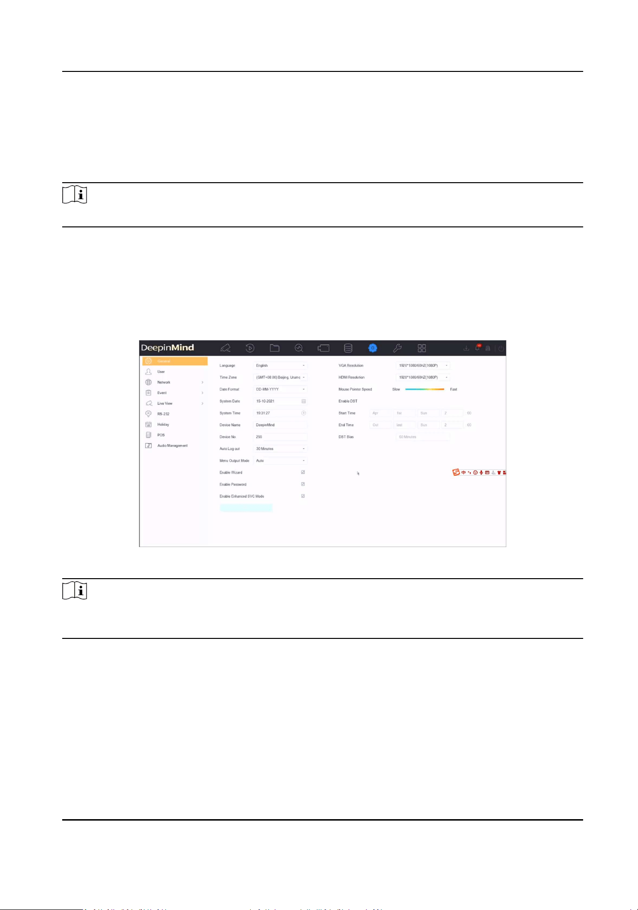
15.3 Audio Management
The audio les are used for alarm linkage.
You can import and manage audio les in System → Audio Management .
Note
Before imporng audio les, prepare a backup device with the audio les in it.
15.4 Congure Enhanced SVC Mode
In live view or playback, enhanced SVC mode can be congured to extract frames of the video,
providing beer decoding capacity.
This mode can be enabled if you go to System → General .
Figure 15-1 Enhanced SVC Mode
Note
If the enhanced SVC mode conguraon of the device does not work, go to the Web page of the
camera(s) to enable the enhanced SVC mode.
15.5 Network Detecon
15.5.1 Network Trac Monitoring
Network trac monitoring is the process of reviewing, analyzing and managing network trac for
any abnormality or process that can aect network performance, availability and/or security.
Network Video Recorder User Manual
173
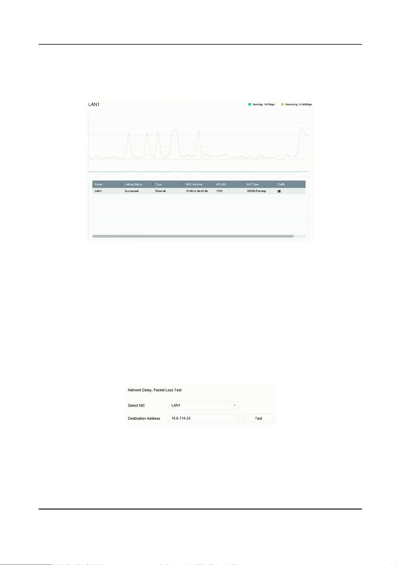
Steps
1. Go to Maintenance → Network → Trac .
2. You can view the real-me network trac status, including MTU (Maximum Transmission Unit),
and network throughput.
Figure 15-2 Network Trac
15.5.2 Test Network Delay and Packet Loss
Network delay is caused by slow response of the device when oversized data informaon is not
limited during transmission under certain network protocol, e.g. TCP/IP. Packet loss test is for
tesng network packet loss rate that is the rao of lost data packet and total number of
transmied data packet.
Steps
1. Go to Maintenance → Network → Network Detecon .
2. Select a network card in Select NIC.
3. Enter the desnaon IP address in Desnaon Address.
4. Click Test.
Figure 15-3 Test Network Delay and Packet Loss
Network Video Recorder User Manual
174

15.5.3 Export Network Packet
Aer the recorder accessing network, you can use USB ash drive to export network packet.
Before You Start
Prepare a USB ash drive to export network packet.
Steps
1. Insert the USB ash drive.
2. Go to Maintenance → Network → Network Detecon .
3. Select network card in Select NIC.
4. Select the USB ash drive in Device Name. You can click Refresh if the connected local backup
device cannot be displayed.
Figure 15-4 Export Network Packet
5. Oponal: Click Status to view the network status.
6. Click Export.
Note
It will export 1 MB data each me as default.
15.5.4 Network Resource Stascs
The remote access, including web browser and client soware, will consume output bandwidth.
You can view the real-me bandwidth stascs.
Steps
1. Go to Maintenance → Network → Network Stat .
Figure 15-5 Network Resource Stascs
2. View the bandwidth stascs, including IP Camera, Remote Live View, Remote Play, Net Total
Idle, etc.
3. Oponal: Click Refresh to obtain the latest data.
Network Video Recorder User Manual
175
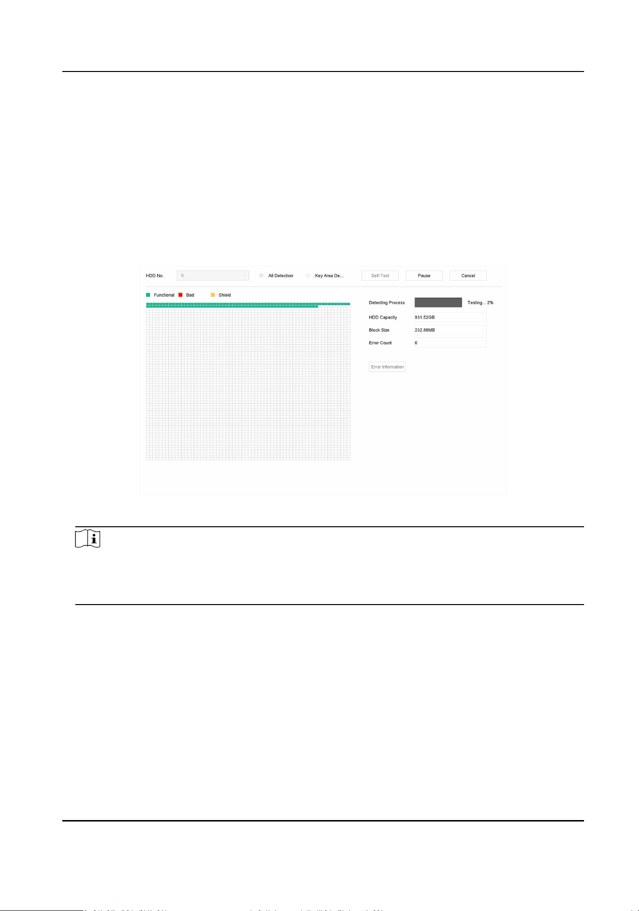
15.6 Storage Device Maintenance
15.6.1 Bad Sector Detecon
Steps
1. Go to Maintenance → HDD Operaon → Bad Sector Detecon .
2. Select the HDD No. you want to congure in the dropdown list.
3. Select All Detecon or Key Area Detecon as the detecon type.
4. Click Self-Test to start the detecon.
Figure 15-6 Bad Sector Detecon
Note
●
You can pause/resume or cancel the detecon.
●
Aer tesng has been completed, you can click Error informaon to see the detailed damage
informaon.
15.6.2 S.M.A.R.T. Detecon
HDD detecon funcons such as the adopng of the S.M.A.R.T. and the Bad Sector Detecon
techniques. S.M.A.R.T. (Self-Monitoring, Analysis, and Reporng Technology) are HDD monitoring
systems to detect various reliability indicators in the hopes of ancipang failures.
Steps
1. Go to Maintenance → HDD Operaon → S.M.A.R.T .
2. Select the HDD to view its S.M.A.R.T. informaon list.
3. Set Self-Test Type.
Network Video Recorder User Manual
176
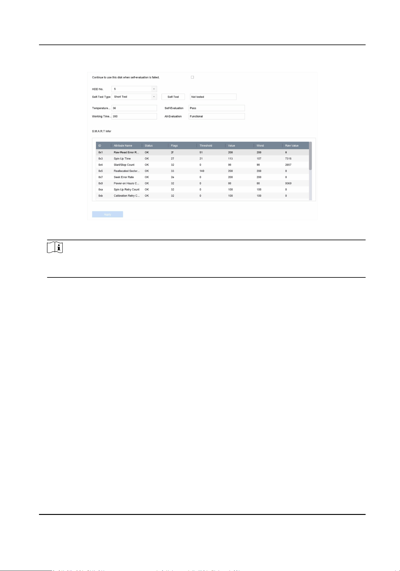
4. Click Self-Test to start the S.M.A.R.T. HDD self-evaluaon.
Figure 15-7 S.M.A.R.T. Sengs Interface
Note
To use the HDD even when the S.M.A.R.T. checking has failed, check Connue to use the disk
when self-evaluaon is failed.
The related informaon of the S.M.A.R.T. is shown, and you can check the HDD status.
15.6.3 HDD Health Detecon
You can view the health status of a 4 TB to 8 TB Seagate HDD that generated aer October 1, 2017.
Use this funcon to help troubleshoot HDD problems. Health Detecon shows a more detailed
HDD status than the S.M.A.R.T. funcon.
Steps
1. Go to Maintenance → HDD Operaon → Health Detecon .
Network Video Recorder User Manual
177
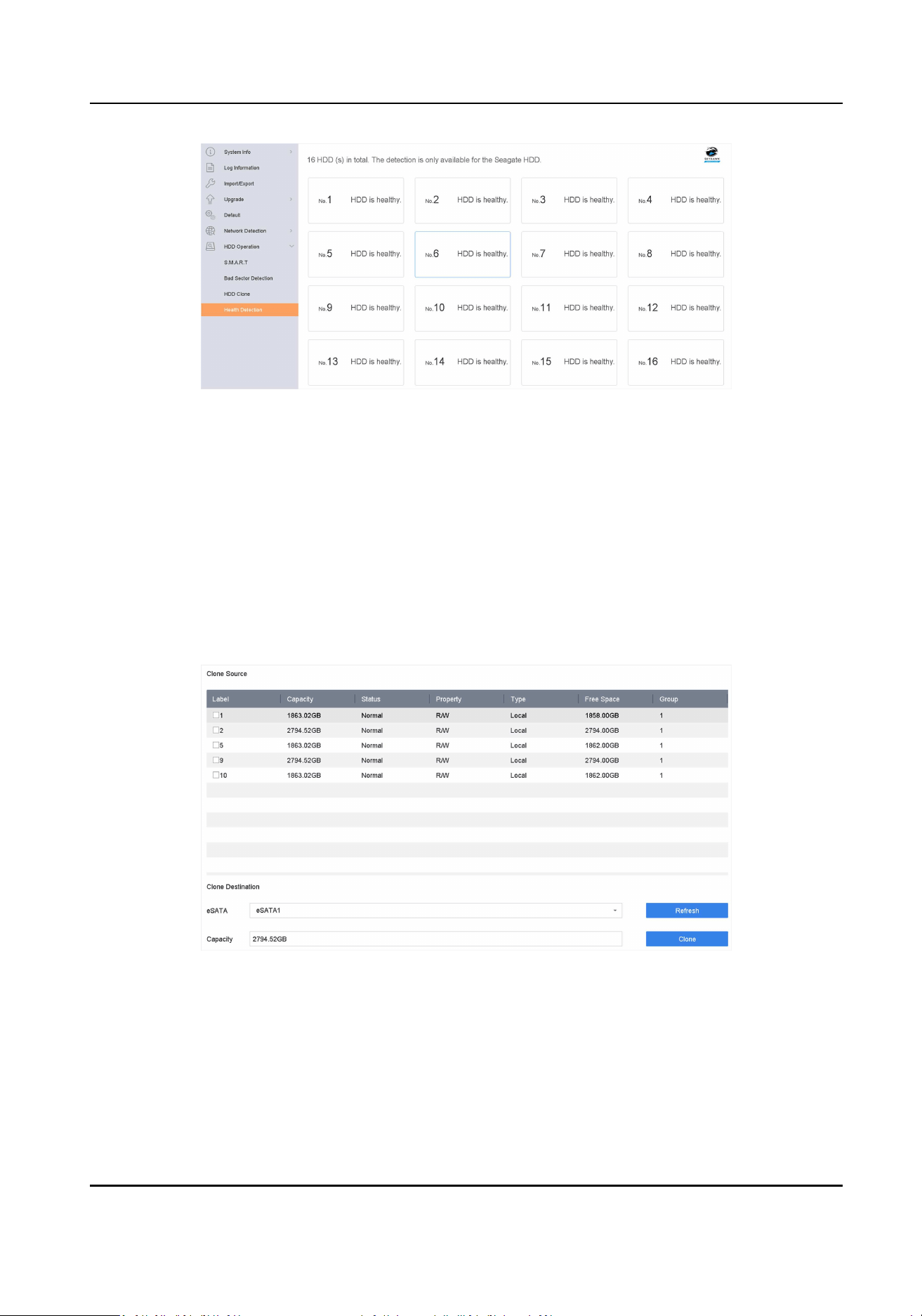
Figure 15-8 Health Detecon
2. Click a HDD to view details.
15.6.4 Congure Disk Clone
Select the HDDs to clone to the eSATA HDD.
Before You Start
Connect an eSATA disk to the device.
Steps
1. Go to Maintenance → HDD Operaon → HDD Clone .
Figure 15-9 HDD Clone
2. Check the HDD to clone. The capacity of the selected HDD must match the capacity of the clone
desnaon.
3. Click Clone.
4. Click Yes on the pop up message box to create the clone.
Network Video Recorder User Manual
178

15.6.5 Repair Database
Repairing database will rebuild all databases. It might help to improve your system speed aer
upgrade.
Steps
1. Go to Storage → Storage Device .
2. Select the drive.
3. Click Repair Database.
4. Click Yes.
Note
●
Repairing database will rebuild all databases. Exisng data will not be aected, but local
search and playback funcons will not be available during the process, you can sll achieve
search and playback funcons remotely via web browser, client soware, etc.
●
Do not pull out the drive, or shut down the device during the process.
●
You can see the repairing progress at Status.
Figure 15-10 Repair Database
15.7 Upgrade Device
Your device rmware can be upgraded with a local backup device or remote FTP server.
15.7.1 Upgrade by Local Backup Device
Before You Start
Connect your device to a local storage device that contains the rmware update le.
Steps
1. Go to Maintenance → Upgrade .
2. Click Local Upgrade to enter the local upgrade interface.
Network Video Recorder User Manual
179

Figure 15-11 Local Upgrade
3. Select the rmware update le from the storage device.
4. Click Upgrade to start upgrading.
Aer the upgrade is completed, the device will reboot automacally to acvate the new
rmware.
15.7.2 Upgrade by FTP
Before You Start
Ensure the network connecon of the PC (running FTP server) and the device are valid and correct.
Run the FTP server on the PC and copy the rmware into the corresponding directory of your PC.
Steps
1. Go to Maintenance → Upgrade .
2. Click FTP to enter the local upgrade interface.
Figure 15-12 FTP Upgrade
3. Enter FTP Server Address.
4. Click Upgrade to start upgrading.
5. Aer the upgrading is complete, reboot the device to acvate the new rmware.
15.7.3 Upgrade by Web Browser
You can upgrade the device by web browser
Aer logging in to the device via web browser, go to Conguraon → System → Maintenance →
Upgrade . Click Browse to upload the rmware, and upgrade the device.
Network Video Recorder User Manual
180
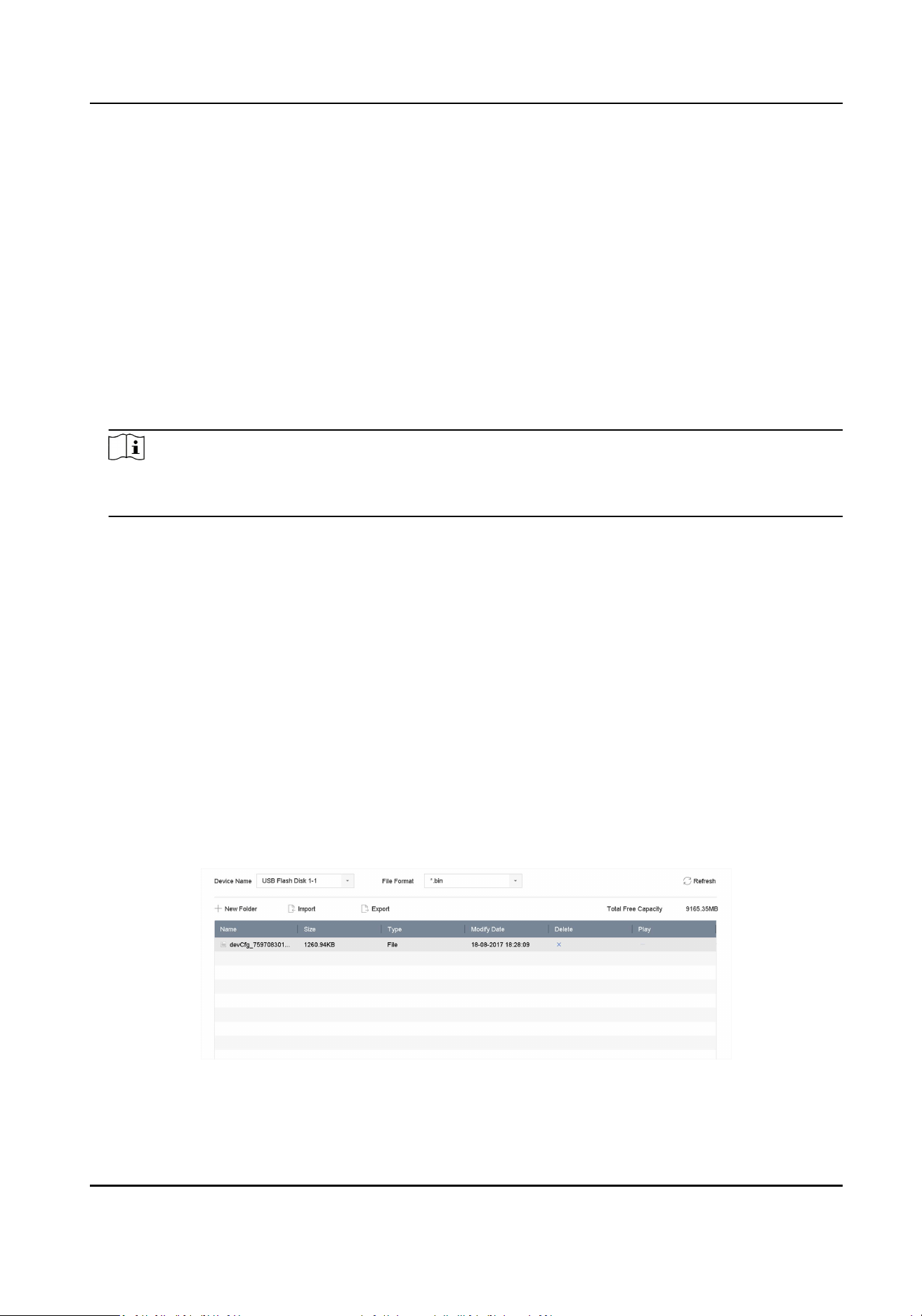
15.7.4 Upgrade by Hik-Connect
Aer logging the device into Hik-Connect, the device would periodically check for the latest
rmware from Hik-Connect. If an upgrade rmware is available, the device will nofy you when
you log in. You can also manually check for the latest rmware.
Before You Start
Ensure the device has successfully connected to Hik-Connect, and it requires to install at least one
read-write HDD for rmware downloading.
Steps
1. Go to Maintenance → Upgrade → Online Upgrade .
2. Click Check Upgrade to manually check and download the latest rmware from Hik-Connect.
Note
The device will automacally check for the latest rmware every 24 hours. If it detects available
upgrade rmware, the device will nofy you when you log in.
3. Oponal: You can switch on Download Latest Package Automacally to automacally download
the latest rmware package.
4. Click Upgrade Now.
15.8 Import/Export Device Conguraon Files
The device conguraon les can be exported to a local device for backup; and the conguraon
les of one device can be imported to mulple devices if they are to be congured with the same
parameters.
Before You Start
Connect a storage device to your device. To import the conguraon le, the storage device must
contain the le.
Steps
1. Go to Maintenance → Import/Export .
Figure 15-13 Import/Export Conguraon File
2. Export or import the device conguraon les.
Network Video Recorder User Manual
181
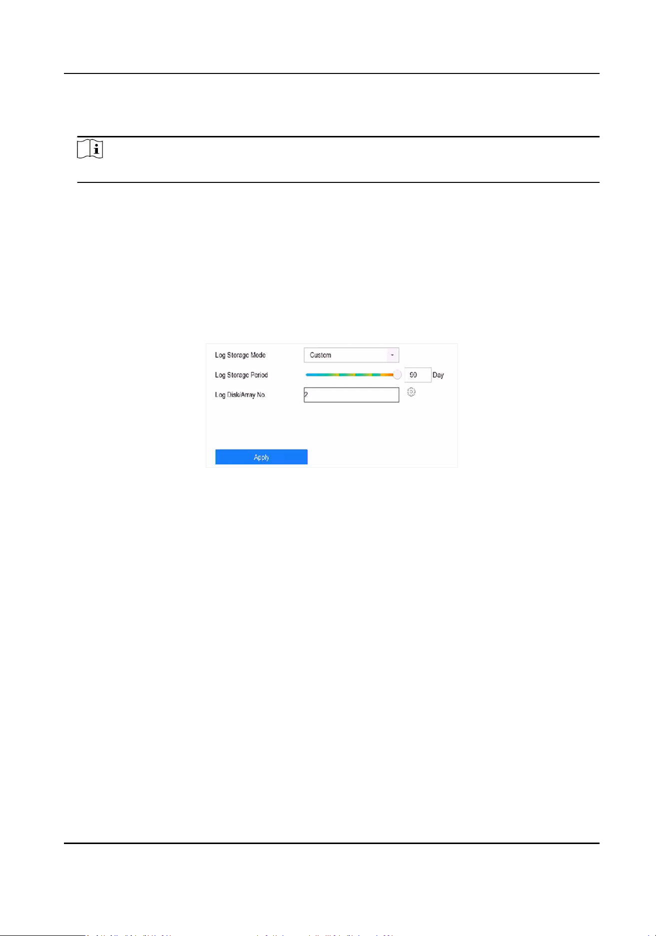
-
Click Export to export conguraon les to the selected local backup device.
-
To import a conguraon le, select the le from the selected backup device and click Import.
Note
Aer having nished imporng conguraon les, the device will reboot automacally.
15.9 Log Management
15.9.1 Log Storage
You can customize the log storage disk and log storage period.
Steps
1. Go to Storage → Advanced .
Figure 15-14 Log Storage
2. Set Log Storage Mode.
System
Default
Each disk will allocate a certain space to store logs in 6 months. Aer 6 months,
old logs will be overwrien.
Custom You can set Log Storage Period and allocate Log Disk for log storage. When the
log disk is full, logs that exceed the period will be overwrien.
3. Click Apply.
15.9.2 Search & Export Log Files
The device operaon, alarm, excepon, and informaon can be stored in log les, which can be
viewed and exported at any me.
Steps
1. Go to Maintenance → Log Info .
Network Video Recorder User Manual
182
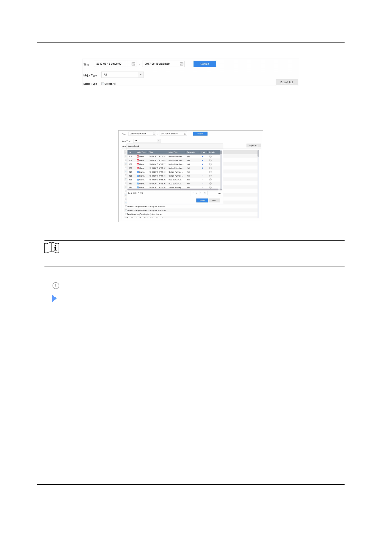
Figure 15-15 Log Search Interface
2. Set the log search condions, including the me, major type and minor type.
3. Click Search to start searching the log les.
4. The matched log les will be displayed on the list, as shown below.
Figure 15-16 Log Search Results
Note
Up to 2,000 log les can be displayed each me.
5. Related Operaon:
Click or double-click it to view detailed informaon.
Click it to view the related video le.
Export/Export ALL Click it to export all the system logs to the storage device.
15.9.3 Upload Logs to the Server
You can upload system logs to the server for backup.
Steps
1. Go to System → Network → Advanced → Log Server Sengs .
Network Video Recorder User Manual
183
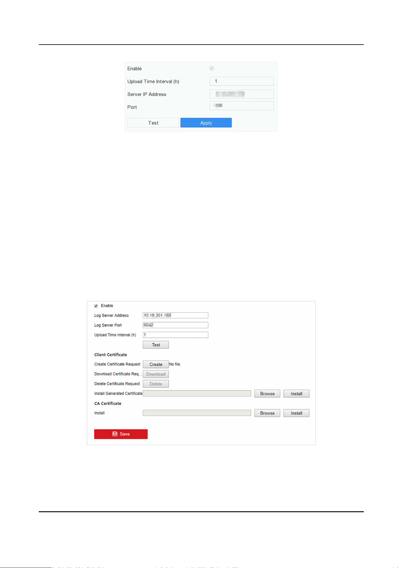
Figure 15-17 Log Server Sengs
2. Check Enable
3. Set Upload Time, Server IP Address, and Port.
4. Oponal: Click Test to test if parameters are valid.
5. Click Apply.
15.9.4 One-Way Authencaon
You can install a CA cercate (from the server) to your device to authorize the server via web
browser. It would improve the log communicaon security.
Before You Start
●
Download the CA cercate from the server.
●
Ensure log server parameters are valid.
Steps
1. Go to Conguraon → Network → Advanced Sengs → Log Server Conguraon .
Figure 15-18 One-Way Authencaon
2. Install the CA cercate in CA Cercate.
3. Oponal: Click Test to test if the connecon is valid.
Network Video Recorder User Manual
184
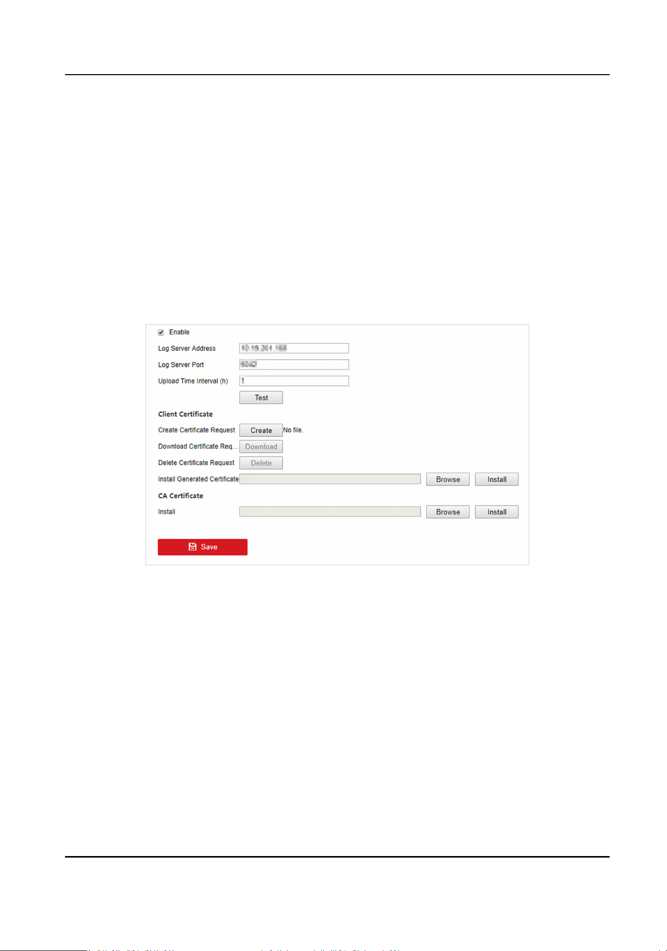
4. Click Save.
15.9.5 Two-Way Authencaon
You can install a CA cercate (from the server) to your device to authorize the server, and create a
cercate (from your device) to authorize your device by the server. This would improve the log
communicaon security. Two-way authencaon can be congured via web browser.
Before You Start
●
Download the CA cercate from the server.
●
Ensure log server parameters are valid.
Steps
1. Go to Conguraon → Network → Advanced Sengs → Log Server Conguraon .
Figure 15-19 Two-Way Authencaon
2. Install the CA cercate in CA Cercate.
3. Click Create in Client Cercate, and follow the pop-up to create the cercate.
4. Click Download to download the cercate le to a desired locaon.
5. Upload the downloaded cercate le to the server, and the server will return the cercate
key.
6. Open the cercate as a text le, and modify it by the cercate key as the server returned.
7. Install the modied cercate in Client Cercate.
8. Oponal: Click Test to test if the connecon is valid.
9. Click Save.
Network Video Recorder User Manual
185
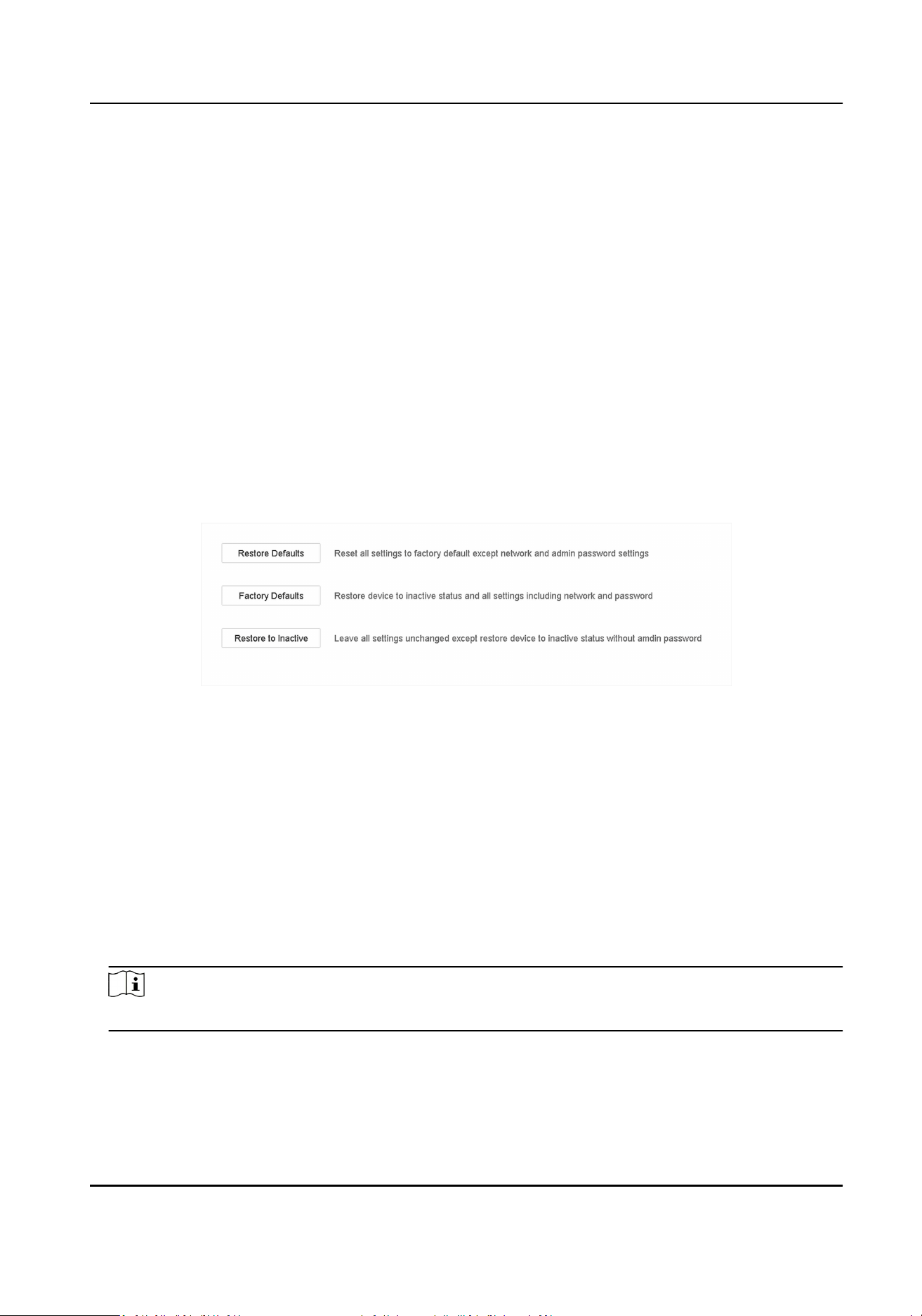
15.10 Export Diagnosc Informaon
When excepons occur, you can export diagnosc informaon via web browser, and check it.
Steps
1. Go to Conguraon → System → Maintenance → Diagnose via web browser.
2. Check Export Diagnosc Informaon.
3. Click Save.
4. Click Diagnose Informaon.
5. Set the saving path and le name as your desire.
6. Save the le.
15.11 Restore Default Sengs
Steps
1. Go to Maintenance → Default .
Figure 15-20 Restore Default Sengs
2. Select the restore type from the following three opons.
Restore Defaults
Restore all parameters, except the network (including IP address, subnet mask, gateway,
MTU, NIC working mode, default route, server port, etc.) and user account parameters, to the
factory default sengs.
Factory Defaults
Restore all parameters to the factory default sengs.
Restore to Inacve
Restore the recorder to inacve status.
Note
The recorder will reboot automacally aer restoring to the default sengs.
Network Video Recorder User Manual
186

15.12 Schedule Reboot
The device will automacally restart according to the schedule.
Steps
1. Go to Maintenance → System Service → System Service → Schedule Reboot .
2. Check Enable.
3. Set the reboot schedule.
4. Click Apply.
15.13 Security Management
15.13.1 Congure ONVIF
ONVIF protocol allows the connecon with third-party cameras. The added user accounts have the
permission to connect other devices via ONVIF protocol.
Steps
1. Go to Maintenance → System Service → ONVIF .
2. Check Enable ONVIF to enable the ONVIF access management.
Note
ONVIF protocol is disabled by default.
3. Click Add.
4. Enter User Name, and Password
Cauon
We highly recommend you create a strong password of your own choosing (Using a minimum of
8 characters, including at least three of the following categories: upper case leers, lower case
leers, numbers, and special characters.) in order to increase the security of your product. And
we recommend you reset your password regularly, especially in the high security system,
reseng the password monthly or weekly can beer protect your product.
5. Select Level as Media User, Operator or Admin.
6. Click OK.
15.13.2 IP/MAC Address Filter
The address lter decides whether to allow or forbid specic IP/MAC address to get access to your
device.
Steps
1. Go to Maintenance → System Service → Address Filter .
Network Video Recorder User Manual
187
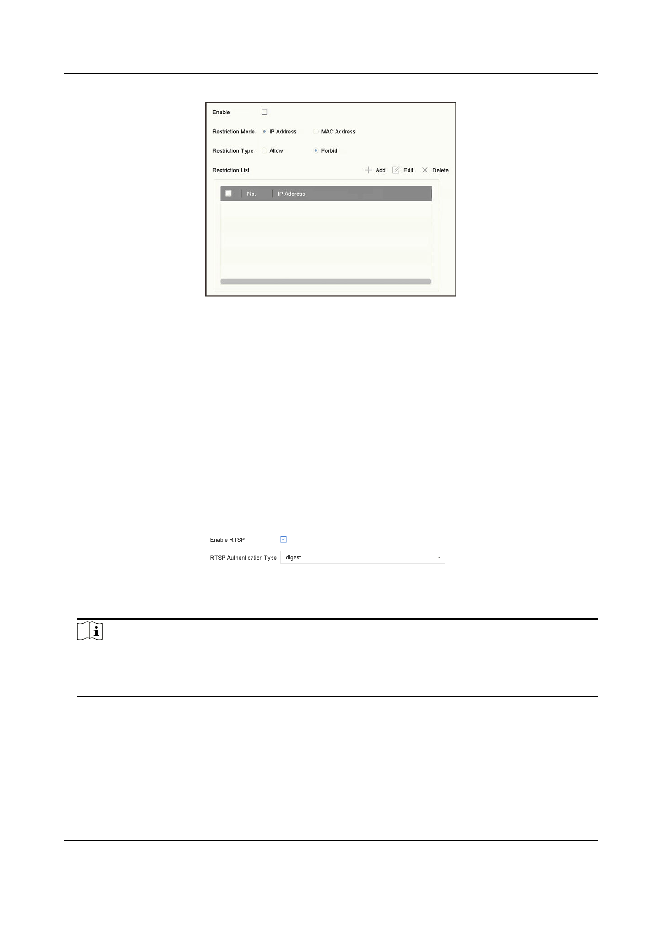
Figure 15-21 Address Filter
2. Check Enable.
3. Select Restricon Mode. Choose to lter by IP address or MAC Address.
4. Select Restricon Type. The device mechanism will allow or forbid specic IP/MAC address to
get access to your device.
5. Oponal: Set Restricon List. You can add, edit or delete address.
6. Click Apply to save the sengs.
15.13.3 RTSP Authencaon
You can specically secure the stream data of live view by seng the RTSP authencaon.
Steps
1. Go to System → System Service → System Service .
Figure 15-22 RTSP Authencaon
2. Select RTSP Authencaon Type.
Note
Two authencaon types are selectable, if you select digest, only the request with digest
authencaon can access the video stream by the RTSP protocol via the IP address. For security
reasons, it is recommended to select digest as the authencaon type.
3. Click Apply.
4. Restart the device to take eect the sengs.
Network Video Recorder User Manual
188

15.13.4 ISAPI Service
ISAPI (Internet Server Applicaon Programming Interface) is an open protocol based on HTTP,
which can realize the communicaon between the system devices (e.g., network camera, NVR,
etc.). The device is as a server, the system can nd and connect the device.
Steps
1. Go to System → System Service → System Service .
2. Check Enable ISAPI.
3. Click Apply.
4. Restart the device to take eect the sengs.
15.13.5 HTTP Authencaon
If you need to enable the HTTP service, you can set HTTP authencaon to enhance access
security.
Steps
1. Go to Maintenance → System Service → System Service .
Figure 15-23 HTTP Authencaon
2. Check Enable HTTP.
3. Select HTTP Authencaon Type.
Note
Two authencaon types are selectable, for security reasons, it is recommended to select digest
as the authencaon type.
4. Click Apply to save the sengs.
5. Restart the device to take eect the sengs.
15.13.6 IP Camera Occupaon Detecon
Aer enabling the feature, when search IP camera in Number of Unadded Online Device interface,
the status of IP camera the has been added by other device will show as
Steps
1. Go to System → System Service → System Service .
2. Check Enable IP Camera Occupaon Detecon.
3. Click Apply to save the sengs. And reboot device to take eect the sengs.
Network Video Recorder User Manual
189

Chapter 16 Appendix
16.1 Glossary
Dual-Stream
Dual-stream is a technology used to record high resoluon video locally while transming a
lower resoluon stream over the network. The two streams are generated by the DVR, with the
main stream having a maximum resoluon of 1080P and the sub-stream having a maximum
resoluon of CIF.
DVR
Acronym for Digital Video Recorder. A DVR is device that is able to accept video signals from
analog cameras, compress the signal and store it on its hard drives.
HDD
Acronym for Hard Disk Drive. A storage medium which stores digitally encoded data on plaers
with magnec surfaces.
DHCP
Dynamic Host Conguraon Protocol (DHCP) is a network applicaon protocol used by devices
(DHCP clients) to obtain conguraon informaon for operaon in an Internet Protocol
network.
HTTP
Acronym for Hypertext Transfer Protocol. A protocol to transfer hypertext request and
informaon between servers and browsers over a network.
PPPoE
PPPoE, Point-to-Point Protocol over Ethernet, is a network protocol for encapsulang Point-to-
Point Protocol (PPP) frames inside Ethernet frames. It is used mainly with ADSL services where
individual users connect to the ADSL transceiver (modem) over Ethernet and in plain Metro
Ethernet networks.
DDNS
Dynamic DNS is a method, protocol, or network service that provides the capability for a
networked device, such as a router or computer system using the Internet Protocol Suite, to
nofy a domain name server to change, in real me (ad-hoc) the acve DNS conguraon of its
congured hostnames, addresses or other informaon stored in DNS.
Hybrid DVR
A hybrid DVR is a combinaon of a DVR and NVR.
NTP
Acronym for Network Time Protocol. A protocol designed to synchronize the clocks of
computers over a network.
Network Video Recorder User Manual
190

NTSC
Acronym for Naonal Television System Commiee. NTSC is an analog television standard used
in such countries as the United States and Japan. Each frame of an NTSC signal contains 525
scan lines at 60Hz.
NVR
Acronym for Network Video Recorder. An NVR can be a PC-based or embedded system used for
centralized management and storage for IP cameras, IP Domes and other DVRs.
PAL
Acronym for Phase Alternang Line. PAL is also another video standard used in broadcast
televisions systems in large parts of the world. PAL signal contains 625 scan lines at 50Hz.
PTZ
Acronym for Pan, Tilt, Zoom. PTZ cameras are motor driven systems that allow the camera to
pan le and right, lt up and down and zoom in and out.
USB
Acronym for Universal Serial Bus. USB is a plug-and-play serial bus standard to interface devices
to a host computer.
16.2 Communicaon Matrix
Please scan the QR code below to view the communicaon matrix document.
Figure 16-1 Communicaon Matrix
16.3 Device Command
Please scan the QR code below to view the device command document.
Network Video Recorder User Manual
191

Figure 16-2 Device Command
16.4 Frequently Asked Quesons
16.4.1 Why is there a part of channels displaying “No Resource” or turning black
screen in mul-screen live view?
Reason
1. Sub-stream resoluon or bitrate sengs is inappropriate.
2. Connecng sub-stream failed.
Soluon
1. Go to Camera → Video Parameters → Sub-Stream . Select the channel, and turn down the
resoluon and max. bitrate (resoluon shall be less than 720p, max. bitrate shall be less than
2048 Kbps).
Note
If your video recorder noes not support this funcon, you can log in to the camera, and
adjust video parameters via web browser.
2. Properly set the sub-stream resoluon and max. bitrate (resoluon shall be less than 720p, max.
bitrate shall be less than 2048 Kbps), then delete the channel and add it back again.
16.4.2 Why is the video recorder nofying the stream type is not supported?
Reason
The camera encoding format mismatches with the video recorder.
Network Video Recorder User Manual
192

Soluon
If the camera is using H.265/MJPEG for encoding, but video recorder does not support H.265/
MJPEG, change the camera encoding format to the same as video recorder.
16.4.3 Why is the video recorder nofying risky password aer a network camera
is added?
Reason
The camera password is too weak.
Soluon
Change the camera password.
Warning
We highly recommend you create a strong password of your own choosing (Using a minimum of 8
characters, including at least three of the following categories: upper case leers, lower case
leers, numbers, and special characters.) in order to increase the security of your product. And we
recommend you reset your password regularly, especially in the high security system, reseng the
password monthly or weekly can beer protect your product.
16.4.4 How to improve the playback image quality?
Reason
Recording parameter sengs are inappropriate.
Soluon
Go to Camera → Video Parameters . Increase resoluon and max. bitrate, and try again.
16.4.5 How to conrm the video recorder is using H.265 to record video?
Soluon
Check if the encoding type at live view toolbar is H.265.
16.4.6 Why is the meline at playback not constant?
Network Video Recorder User Manual
193

Reason
1. When the video recorder is using event recording, it only records video when event occurs.
Hence the video may not be connuous.
2. Excepon occurs, such as the device oine, HDD error, record excepon, network camera
oine, etc.
Soluon
1. Ensure the recording type is connuous recording.
2. Go to Maintenance → Log Info . Search the log le during the video me period. See if there
are unexpected events, such as HDD error, record excepon, etc.
16.4.7 Why is the video recorder nofying the network is unreachable when a
network camera is being added?
Reason
1. The IP address or port of network camera is incorrect.
2. The network between video recorder and camera is disconnected.
Soluon
1. Go to Camera → Camera → IP Camera . Click of the selected camera, and edit its IP address
and port. Ensure the video recorder and camera is using the same port.
2. Go to Maintenance → Network → Detecon . Enter the IP address of network camera in
Desnaon Address, and click Test to see if the network is reachable.
16.4.8 Why is the IP address of network camera being changed automacally?
Reason
When network camera and video recorder are using the same switch but in dierent subnets, the
video recorder will change the IP address of network camera to the same subnet as itself.
Soluon
When adding camera, click Custom Add to add camera.
16.4.9 Why is the video recorder nofying IP conict?
Reason
The video recorder uses the same IP address as other devices.
Network Video Recorder User Manual
194

Soluon
Change the IP address of video recorder. Ensure it is not the same as other devices.
16.4.10 Why is image geng stuck when playing back by single or mul-channel
cameras?
Reason
HDD read/write excepon.
Soluon
Export the video, and play it with other devices. If it plays normally on other device, change your
HDD, and try again.
16.4.11 Why does my video recorder make a beeping sound aer boong?
Reason
1. The front panel is not fastened (for the device which its front panel is removable).
2. HDD error, or do not have HDD.
Soluon
1. If it makes connuous beeps, and your device's front panel is removable, ensure the front panel
is fastened.
2. If it makes non-connuous beeps (3 long, 2 short), take HDD error as an example, check if the
device has installed HDD. If not, you can go to System → Event → Normal Event → Excepon ,
and uncheck Event Hint Conguraon to disable HDD error event hint.
Check if the HDD is inialized. If not, go to Storage > Storage Device to inialize the HDD.
Check if the HDD is broken. You can change it, and try again.
16.4.12 Why is there no recorded video aer the moon detecon is set?
Reason
1. The recording schedule is incorrect.
2. The moon detecon event seng is incorrect.
3. HDD excepon.
Network Video Recorder User Manual
195

Soluon
1. The recording schedule is setup correctly by following the steps listed in Conguring Record/
Capture Schedule.
2. The moon detecon area is congured correctly. The channels are being triggered for moon
detecon (See Conguring Moon Detecon).
3. Check if the device has installed HDD.
Check if the HDD is inialized. If not, go to Storage > Storage Device to inialize the HDD.
Check if the HDD is broken. You can change it, and try again.
16.4.13 Why is the video sound quality not good?
Reason
1. The audio input device does not have a good eect in sound collecon.
2. Interference in transmission.
3. The audio parameter is not properly set.
Soluon
1. Check if the audio input device is working properly. You can change another audio input device,
and try again.
2. Check the audio transmission line. Ensure all lines are well connected or welded, and there is no
electromagnec interference.
3. Adjust the audio volume according to the environment and audio input device.
Network Video Recorder User Manual
196

UD32688B