Loading ...
Loading ...
Loading ...
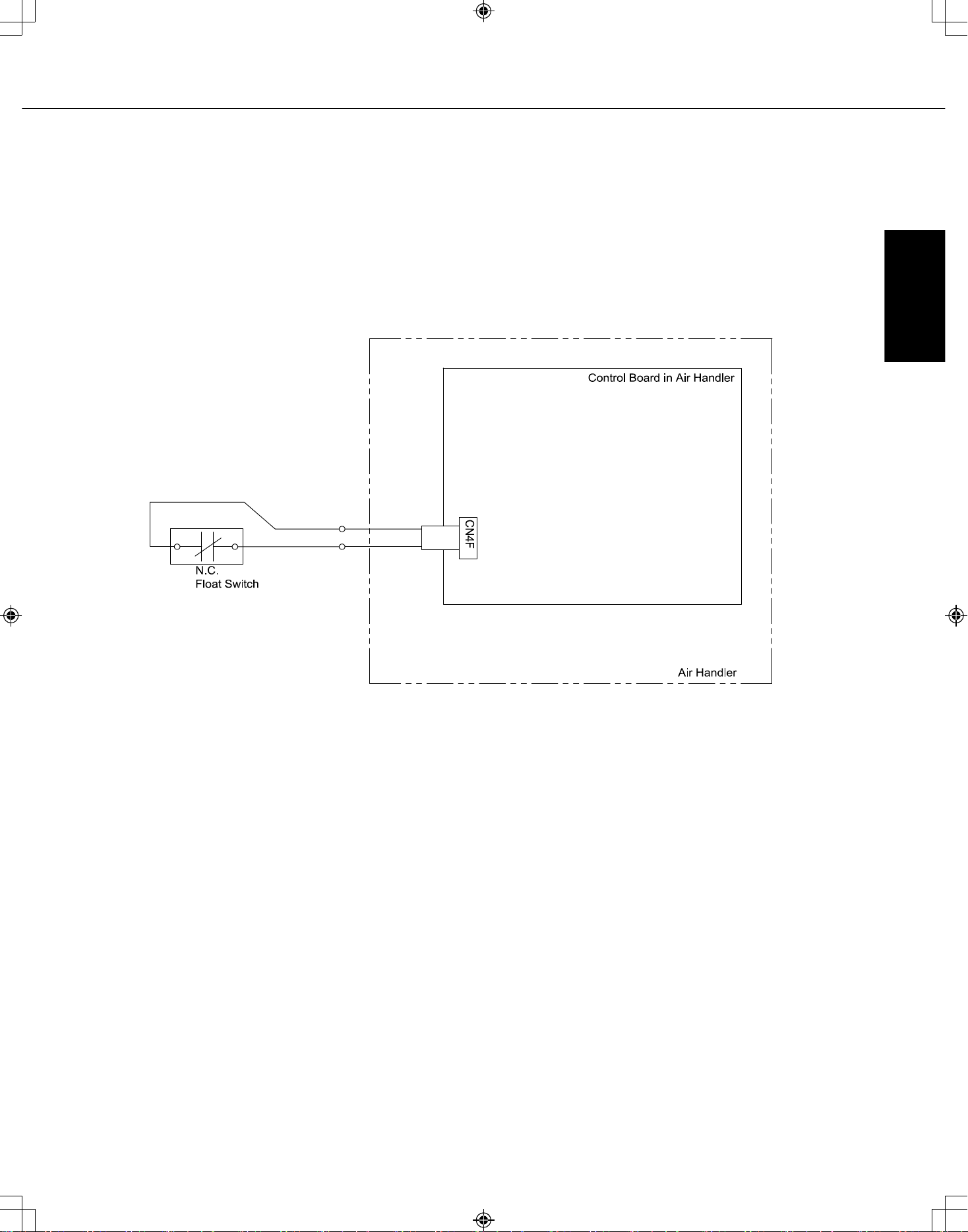
14.3. Condensate overflow safety switch connection (CN4F)
The circuit board is equipped with a connection to attach a condensate safety float switch. The switch
should be a normally closed low voltage rated switch. The switch should be installed in a location that it can
sense a drain blockage causing a rise in water level. This resulting rise in level will cause it to open. The
switch location is to be determined by the installing contractor. When the switch opens, it will cause the LEV
to close, stopping the cooling operation. The fan will continue to run and a fault code will be shown at the
controller. Correcting the problem and closing the switch will be required before normal operation can re-
sume. See installation below:
13.3. Condensate overlow safety switch connection
condensate safety loat switch. The switch should be a normally
*MVZ-A36 in Downlow External Static pressure: 0.60
downlow position.
Vertical, Horizontal Left, Horizontal Right External Static
Mode/Function
Setting No. of Mode/
Downlow External Static Pressure Setting
Mode/Function Mode/Function
*MVZ-A36 in Downlow External Static pressure: 0.60
Locate the CN4F connector on the
control board. Carefully remove the
connector with the jumper from the
board. Cut the jumper on the CN4F
connector and wire a normally
closed safety loat switch across
the wires. Carefully reinstall the
connector back on the board.
When the Normally Closed Float
Switch opens, the Indoor unit will
turn off.
SVZ-KP12,18, 24, 30, 36NA
Specifications are subject to change without notice. 47 © 2022 Mitsubishi Electric US, Inc.
ENGLISH
Loading ...
Loading ...
Loading ...