HUSSONG MANUFACTURING CO., INC.
INSTALLATION AND
OPERATION MANUAL
ͷ Do not store or use gasoline or other
ammable vapors and liquids in the vicinity
of this or any other appliance.
ͷ WHAT TO DO IF YOU SMELL GAS
• Do not try to light any appliance.
• Do not touch any electrical switch; do
not use any phone in your building.
• Leave the building immediately.
• Immediately call your gas supplier from
a neighbor’s phone. Follow the gas
supplier’s instructions.
• If you cannot reach your gas supplier,
call the re department.
ͷ Installation and service must be performed
by a qualied installer, service agency or
the gas supplier.
WARNING:
FIRE OR EXPLOSION HAZARD
Failure to follow safety warnings exactly
could result in serious injury, death, or
property damage.
This appliance may be installed in
an aftermarket, permanently located,
manufactured home (USA only) or mobile
home, where not prohibited by local codes.
This appliance is only for use with the type
of gas indicated on the rating plate. This
appliance is not convertible for use with other
gases, unless a certied kit is used.
INSTALLER: Leave this manual with the appliance.
CONSUMER: Retain this manual for future reference.
English and French installation manuals are available through your
local dealer. Visit our website www.kozyheat.com.
Les manuels d’installation en français et en anglais sont disponibles
chez votre détaillant local. Visitez
www.kozyheat.com
.
DANGER
HOT GLASS WILL
CAUSE BURNS
DO NOT TOUCH GLASS
UNTIL COOLED
NEVER ALLOW CHILDREN
TO TOUCH GLASS
A barrier designed to reduce the risk of burns
from the hot viewing glass is provided with this
appliance and shall be installed for the protection
of children and other at-risk individuals.
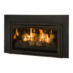
CHASKA 29 MV
Model #CSK-29-MV
Direct Vent Gas Fireplace Insert
Hussong Mfg. Co., Inc.
CSK-29-MV Report No: 18-440
Rev. 9, August 2020
Starting Serial Number: 20 38047 30

#CSK-29-MV R.8 October 2019 Hussong Mfg. Co., Inc. • Kozy Heat Fireplaces 3
Read this manual before installing or operating this appliance.
Please retain this owner’s manual for future reference.
Hussong Manufacturing welcomes you as a new owner of a Kozy Heat gas fireplace. Kozy
Heat products are designed with superi components and materials, assembled with care
by trained crasmen who take pride in their wk. To ensure you receive a quality product,
the burner and valve assembly are 100 percent test-fired, and the complete fireplace is
thoughly inspected befe packaging. Our commitment to quality and customer satisfaction
has remained the same f over 40 years. We oer a complete line of gas and wood fireplaces,
along with stylish accessies to complement any dec. Adding a fireplace is one of the
best ways to increase the value of your home, and we are proud to oer a netwk of dealers
throughout the country to help make your experience everything you imagine. We pride
ourselves in being dedicated not only to functionality and reliability, but also customer safety.
We oer our continual suppt and guidance to help you achieve the maximum
benet and enjoyment om your Kozy Heat gas fireplace.
Jim Hussong
President
Dudley Hussong
Board Chairman
Homeowner Reference Information
We recommend you record the following information:
Model Name: ____________________________________________
Serial Number: ___________________________________________
Dealership Purchased from: ________________________________
Date purchased/installed: __________________________________
Location of replace: ______________________________________
Dealer phone: ___________________________________________
Notes: ______________________________________________________________________________________________________________
____________________________________________________________________________________________________________________
____________________________________________________________________________________________________________________
____________________________________________________________________________________________________________________
CON GRAT ULAT ION S!


#CSK-29-MV R.8 October 2019 Hussong Mfg. Co., Inc. • Kozy Heat Fireplaces TABLE OF CONTENTS 5
TABLE OF CONTENTS
TABLE OF CONTENTS .....................................................................5
1.0 INTRODUCTION ......................................................................7
1.1 Appliance Certication ............................................................................. 7
1.2 California Proposition 65 Warning ........................................................ 7
1.3 Requirements for the Commonwealth of Massachusetts ............ 7
2.0 SPECIFICATIONS .....................................................................8
2.1 Heating Specications .............................................................................. 8
2.2 Electrical Specications ............................................................................ 8
2.3 Appliance Dimensions .............................................................................. 9
2.4 Part Assembly Overview .......................................................................... 10
2.5 Safety Barrier Dimensions ........................................................................ 11
3.0 EXISTING FIREPLACE REQUIREMENTS .................................12
3.1 Appliance Placement Considerations ................................................. 12
3.2 Existing Fireplace Specications ........................................................... 12
4.0 TERMINATION LOCATION ...................................................... 13
4.1 Chimney Vent Termination Clearances ............................................... 13
4.2 Co-linear to Co-axial Vent Terminations .............................................13
5.0 INSTALLATION PREPARATION ...............................................14
5.1 Inspect and Clean Existing Chimney ................................................... 14
5.2 Flue Damper ................................................................................................. 14
5.3 Gas Line .......................................................................................................... 14
5.4 Electrical Wiring ........................................................................................... 14
5.5 Fireplace Conversion ................................................................................ 14
6.0 INSTALLATION ........................................................................15
6.1 Approved Vent Systems ............................................................................ 15
6.2 Kozy Heat #816 and #816-CAP...............................................................15
6.3 Co-linear to Co-axial Combined Venting ............................................ 16
6.4 Remove Vent Adapter ............................................................................... 17
6.5 Run Vent System.......................................................................................... 17
6.6 Connect Vent Pipe to Vent Adapter ...................................................... 17
6.7 Place and Secure Appliance ....................................................................18
6.8 Outdoor Covered Fireplace Installation .............................................. 19
7.0 GAS LINE CONNECTION .........................................................21
7.1 Gas Conversion (sold separately) .......................................................... 21
7.2 Gas Line Installation ................................................................................... 21
8.0 FACING AND FINISHING .........................................................22
8.1 Facing and Finishing Requirements ..................................................... 22
8.2 #CK29-LMK Low Mantel Kit ..................................................................... 24
8.3 Shroud Installation ..................................................................................... 26
8.4 Safety Barrier Installation ......................................................................... 26
9.0 GAS FIREPLACE INSERT SETUP .............................................27
9.1 Glass Assembly ............................................................................................ 27
9.2 #CK29-500 Log Set Installation .............................................................. 28
9.3 Control Board Removal and Installation ............................................. 29
10.0 ELECTRICAL INFORMATION ................................................ 30
10.1 Electrical Specications .......................................................................... 30
10.2 Wiring Requirements .............................................................................. 30
11.0 OPERATING INSTRUCTIONS ................................................ 32
11.1 Flame Height and Heat Output Adjustment .................................. 33
11.2 7 Day Time-out Pilot-on-Demand Installations ............................. 33
12.0 ADJUSTMENT ........................................................................34
12.1 Gas Pressure Testing ................................................................................ 34
12.2 Burner Flame Adjustments ................................................................... 35
13.0 TROUBLESHOOTING.............................................................36
14.0 MAINTENANCE......................................................................38
14.1 Firebox .......................................................................................................... 38
14.2 Fan ................................................................................................................. 38
14.3 Vent System ................................................................................................ 38
14.4 Glass Assembly .......................................................................................... 38
14.5 Burner and Pilot System ........................................................................ 39
15.0 REPLACEMENT PARTS LIST..................................................40
LIMITED LIFETIME WARRANTY ....................................................41


#CSK-29-MV R.8 October 2019 Hussong Mfg. Co., Inc. • Kozy Heat Fireplaces INTRODUCTION 7
1.0 INTRODUCTION
1.1 Appliance Certication
Laboratory: PFS in Cottage Grove, Wisconsin
Standards:
ANSI Z21.88-2017/CSA 2.33-2017, Vented Gas Fireplace Heaters
CSA 2.17 - 2017, Gas-Fired Appliances for Use at High Altitudes
This installation must conform with local codes, or in the absence of
local codes, with the National Fuel Gas Code, ANSI Z223.1/NFPA 54, or
the Natural Gas and Propane Installation Code, CSA B149.1.
1.2 California Proposition 65 Warning
WARNING: This product can expose you to chemicals including
Carbon Monoxide, that is an externally vented by-product of fuel
combustion, which is [are] known to the State of California to
cause cancer, birth defects, or other reproductive harm. For more
information, visit www.P65Warnings.ca.gov.
1.3 Requirements for the
Commonwealth of Massachusetts
The following requirements reference various Massachusetts and
national codes not contained in this manual.
For all sidewall horizontally vented gas fueled equipment installed
in every dwelling, building or structure used in whole or in part for
residential purposes, including those owned or operated by the
Commonwealth and where the side wall exhaust vent termination
is less than (7) feet above nished grade in the area of the venting,
including but not limited to decks and porches, the following
requirements shall be satised:
1.3.1 Installation of Carbon Monoxide Detectors
At time of installation of side wall horizontally vented gas fueled
equipment, the installing plumber or gas-tter shall observe that
a hard wired carbon monoxide detector with an alarm and battery
back-up is installed on the oor level where the gas equipment is
to be installed. In addition, the installing plumber or gas-tter shall
observe that a battery operated or hard wired carbon monoxide
detector is installed on each additional level of the dwelling, building
or structure served by the side wall horizontal vented gas fueled
equipment. It shall be the responsibility of the property owner
to secure the services of qualied licensed professionals for the
installation of hard wired carbon monoxide detectors.
In the event that the side wall horizontally vented gas fueled
equipment is installed in a crawl space or attic, the hard wired carbon
monoxide detector with alarm and battery back-up may be installed
on the next adjacent oor level. In the event that the requirements
of this subdivision can not be met at the time of completion of
installation, the owner shall have a period of thirty (30) days to
comply with the above requirements; provided, however, that during
said thirty (30) day period, a battery operated carbon monoxide
detector with an alarm shall be installed.
1.3.2 Approved Carbon Monoxide Detectors
Each carbon monoxide detector as required in accordance with the
above provisions shall comply with NFPA 720 and be ANSI/UL 2034
listed and IAS certied.
1.3.3 Signage
A metal or plastic identication plate shall be permanently mounted
to the exterior of the building at a minimum of eight (8) feet
above grade directly in line with the exhaust vent terminal for the
horizontally vented gas fueled heating appliance or equipment. The
sign shall read, in print no less the one-half inch (½) in size, “GAS VENT
DIRECTLY BELOW. KEEP CLEAR OF ALL OBSTRUCTIONS”.
1.3.4 Inspection
The state or local gas inspector of the side wall horizontally vented
gas fueled equipment shall not approve the installation unless, upon
inspection, the inspector observes carbon monoxide detectors and
signage installed in accordance with the provisions of 248 CMR 5.08
(2) (a) 1 through 4.
1.3.5 Exemptions
The following equipment is exempt from 248 CMR 5.08 (2) (a) 1
through 4: The equipment listed in Chapter 10 entitled “Equipment
Not Required To Be Vented” in the most current edition of NFPA 54 as
adopted by the Board; and Product Approved side wall horizontally
vented gas fueled equipment installed in a room or structure separate
from the dwelling, building or structure used in whole or in part for
residential purposes.
1.3.6 Manufacturer Requirements
1.3.6.1 Gas Equipment Venting System Provided
When the manufacturer of Product Approved side wall horizontally
vented gas equipment provides a venting system design or venting
system components with the equipment, the instructions provided
by the manufacturer for installation of the equipment and the
venting system shall include:
• Detailed instructions for the installation of the venting system
design or the venting system components; and
• A complete parts list for the venting system design or venting
system.
1.3.7 Gas Equipment Venting
System NOT Provided
When the manufacturer of Product Approved side wall horizontally
vented gas equipment does not provide the parts for venting the
ue gases, but identies “special venting systems”, the following
requirements shall be satised by the manufacturer:
• The referenced “special venting systems” instructions shall
be included with the appliance or equipment installation
instructions and;
• The “special venting systems” shall be Product Approved by the
Board, and the instructions for that system shall include a parts
list and detailed installation instructions.
A copy of all installation instructions for all Product Approved
side wall horizontally vented gas fueled equipment, all venting
instructions, all parts lists for venting instructions, and/or all venting
design instructions shall remain with the appliance or equipment at
the completion of the installation.
8 SPECIFICATIONS Hussong Mfg. Co., Inc. • Kozy Heat Fireplaces #CSK-29-MV R.8 October 2019
2.0 SPECIFICATIONS
2.1 Heating Specications
Natural Gas Propane
Maximum
Input Rating
28,500 Btu/h
8.35 kW
29,000 Btu/h
8.5 kW
Minimum
Input Rating
18,500 Btu/h
5.42 kW
22,000 Btu/h
6.45 kW
Manifold Pressure
(High)
3.5” WC
(0.87 kPa)
10” WC
(2.49 kPa)
Manifold Pressure
(Low)
1.6” WC
(0.40 kPa)
6.4” WC
(1.59 kPa)
Orice Size (DMS) #42 #53
2.1.1 Altitude Adjustment
This appliance may be installed at higher altitudes. Please refer to
National Fuel Gas Code ANSI Z223.1/NFPA 54, CSA-B149.1 Natural
Gas and Propane Installation Code, local authorities, or codes having
jurisdiction in you area regarding derate guidelines.
2.1.1.1 US Installations
Refer to the American Gas Association guidelines for the gas designed
appliances derating method. For elevations above 2,000’ (610m),
input ratings are to be reduced by 4% for each 1,000’ (305m) above
sea level.
2.1.1.2 Canadian Installations
When the appliance is installed at elevations above 4,500’ (1,372m),
the certied high altitude rating shall be reduced at the rate of 4% for
each additional 1,000’ (305m).
2.2 Electrical Specications
• The junction box in this appliance requires 120VAC, 60Hz, and 6
Amps.
• Verify the household breaker is shut o prior to working on any
electrical lines.
• The AC power supply to this appliance must be hot at all times
and shall not have a switch installed in it.
#CSK-29-MV R.8 October 2019 Hussong Mfg. Co., Inc. • Kozy Heat Fireplaces SPECIFICATIONS 9
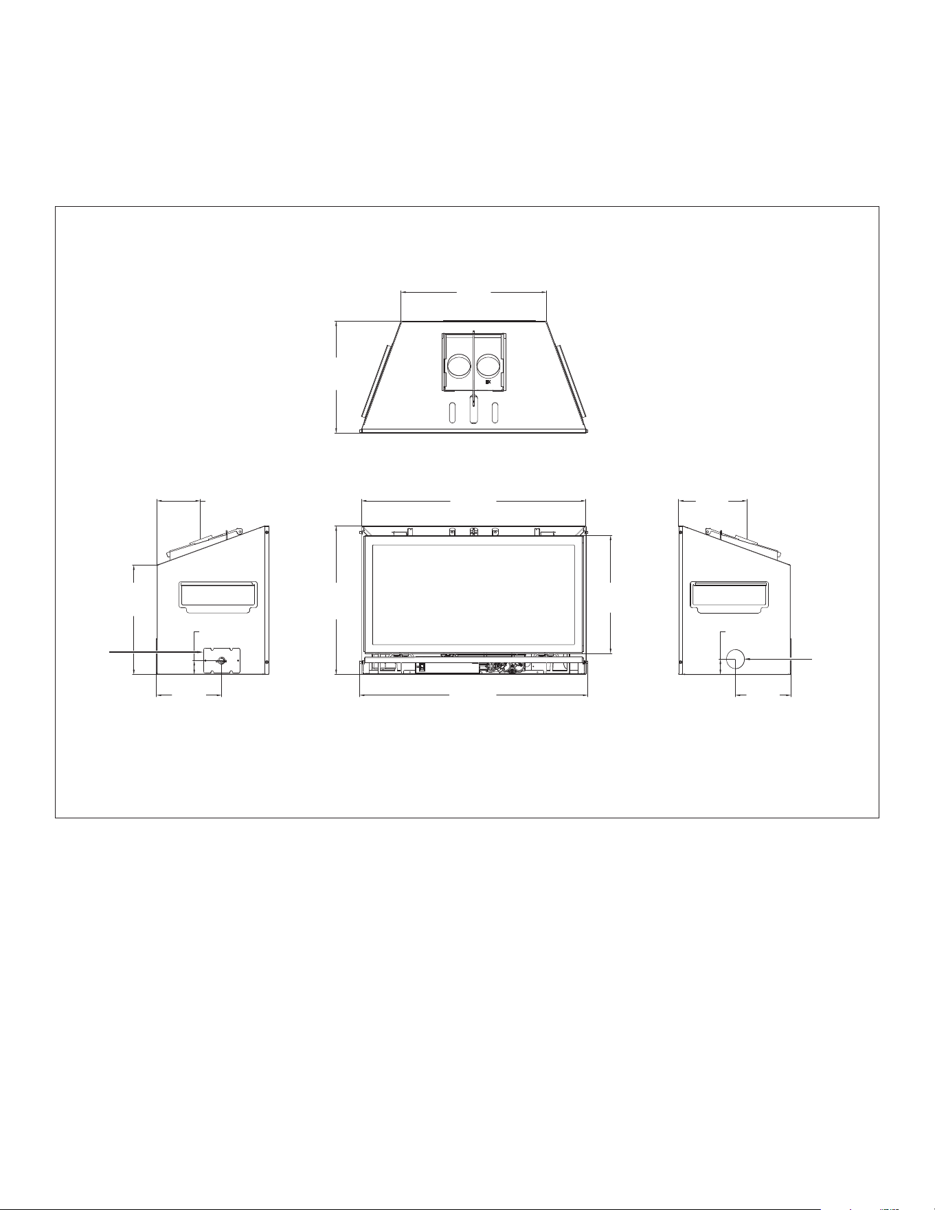
2.3 Appliance Dimensions
Figure 2.1, Appliance Dimensions
14½”
(368mm)
18
7⁄8”
(479mm)
8
7⁄8”
(225mm)
2”
(51mm)
7
3⁄16”
(183mm)
29”
(737mm)
29
½”
(750mm)
15
5⁄16”
(388mm)
19
¼”
(488mm)
5
5⁄8”
(143mm)
14
1⁄8”
(360mm)
8
7⁄16”
(214mm)
1
13⁄16”
(46mm)
ELECTRICAL
ACCESS
GAS LINE
HOLE
LEFT FRONT RIGHT
TOP
10 SPECIFICATIONS Hussong Mfg. Co., Inc. • Kozy Heat Fireplaces #CSK-29-MV R.8 October 2019
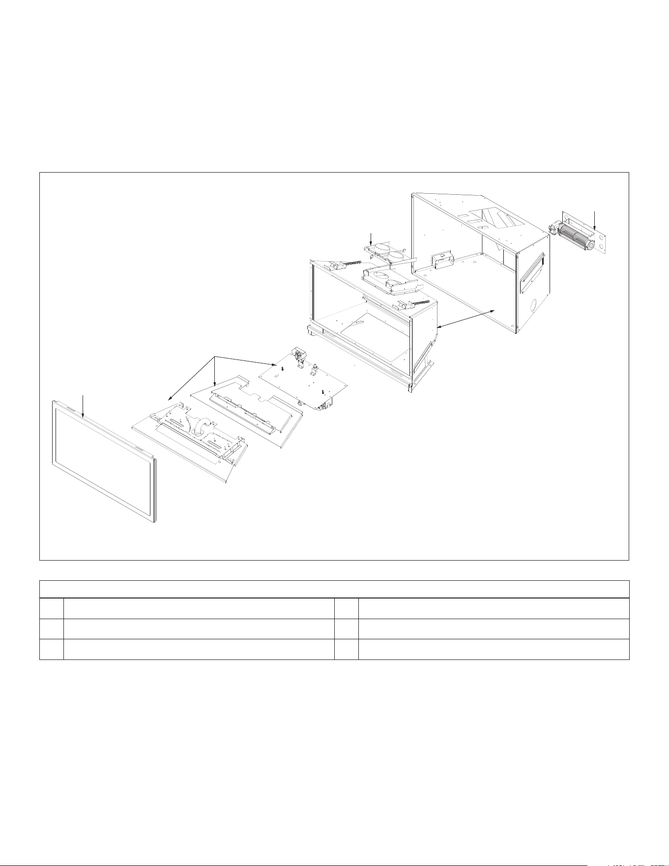
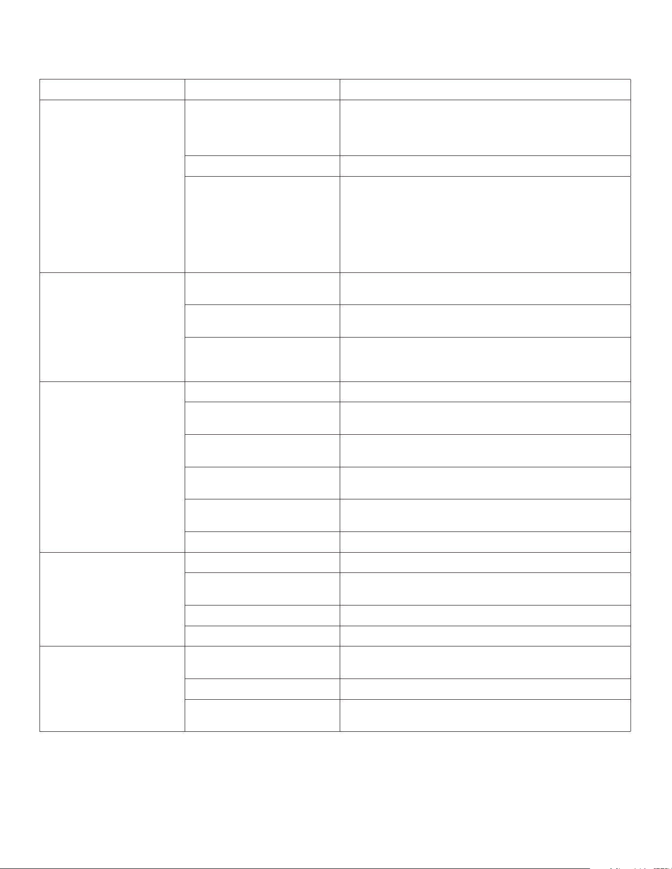
2.4 Part Assembly Overview
WARNING: Failure to position these parts in accordance with these
diagrams, or failure to use only specied approved parts with this
appliance, may result in property damage or personal injury.
Figure 2.2, Proper Positioning of Appliance
B
C
A
D
E
Table 2.1, Field-Assembled Parts
A
Fireplace insert
D
Fan Kit
B
Glass frame assembly
E
Co-linear vent adapter
C
Control board with burner assembly
#CSK-29-MV R.8 October 2019 Hussong Mfg. Co., Inc. • Kozy Heat Fireplaces SPECIFICATIONS 11
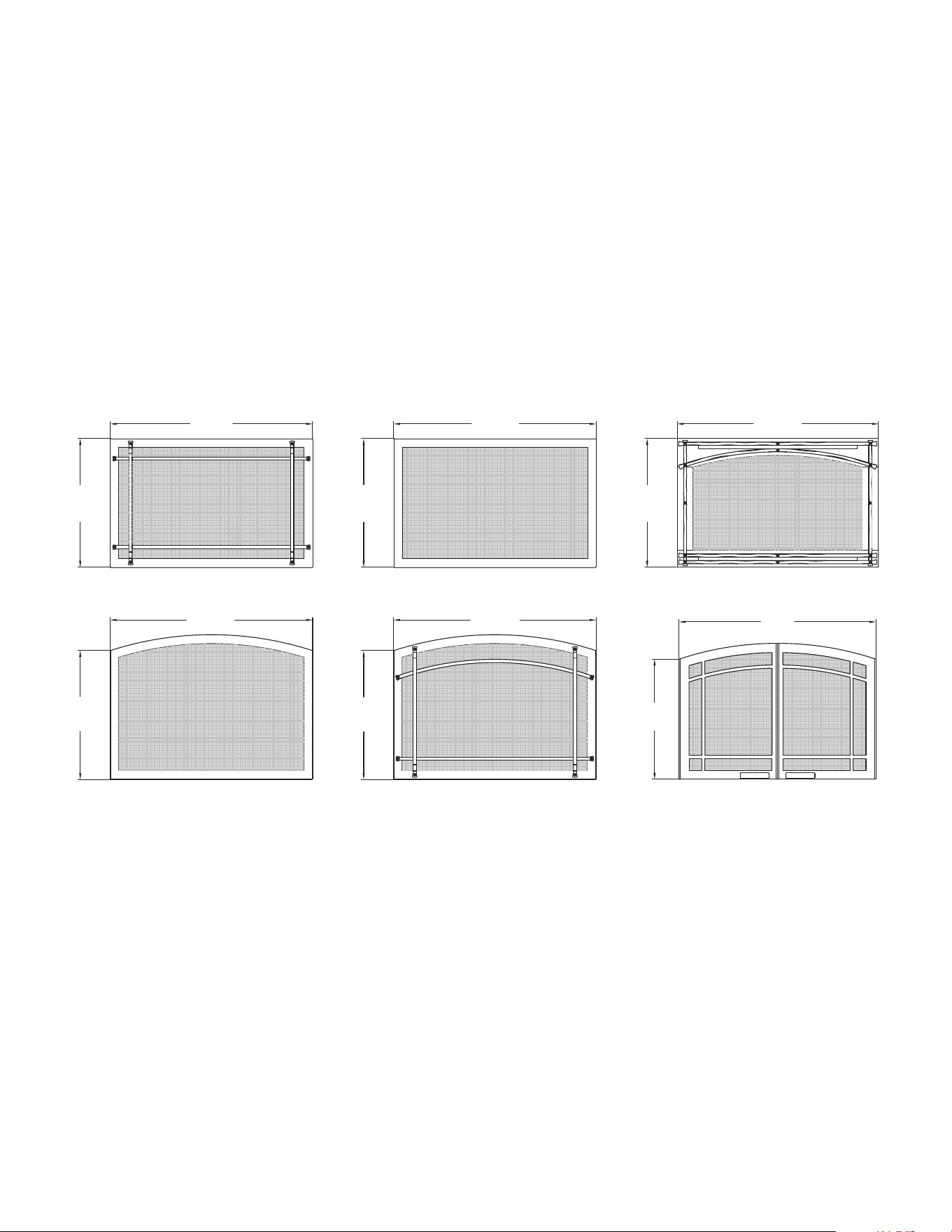
2.5 Safety Barrier Dimensions
WARNING: A barrier designed to reduce the risk of burns from the hot
viewing glass is provided with this appliance and shall be installed for
the protection of children and other at-risk individuals.
If the barrier becomes damaged, the barrier shall be replaced with
Hussong Mfg.’s barriers for this appliance.
IMPORTANT: Consider the height of hearth nish material when
building a replace platform. Proper installation of safety barriers
require the bottom of the replace to be level with nished hearth.
See section 8.4 Safety Barrier Installation on page 26 for installation
and removal of safety barriers.
203⁄16”
(513mm)
31
¾”
(807mm)
31
9⁄16”
(802mm)
20
¼”
(515mm)
20
3⁄16”
(513mm)
31
¾”
(807mm)
20
3⁄16”
(513mm)
31
¾”
(807mm)
31
¾”
(807mm)
20
¼”
(515mm)
18
13⁄16”
(478mm)
31”
(786mm)
CK29-PSF CK29-RSF CK29A-MSF
CK29A-SF CK29A-PSF CK29A-FPDSF2
12 EXISTING FIREPLACE REQUIREMENTS Hussong Mfg. Co., Inc. • Kozy Heat Fireplaces #CSK-29-MV R.8 October 2019
3.0 EXISTING FIREPLACE REQUIREMENTS
3.1 Appliance Placement Considerations
WARNING: Due to high surface temperatures, the replace insert
should be located out of trac and away from furniture and draperies.
• This replace must be installed on a level surface capable of
supporting the replace insert and venting.
• This replace insert may be installed in a bedroom.
• Please be aware of the large amount of heat this replace insert
will produce when determining a location.
3.2 Existing Fireplace Specications
IMPORTANT: Adequate accessibility clearances for servicing and
proper operation must be maintained.
• Any smoke shelves, shields, and baes may be removed if
attached by mechanical fasteners. If necessary, remove rebrick
to obtain at least the minimum opening requirements.
• Cutting of any sheet metal parts of the existing replace is
prohibited.
• A gas line must be able to be installed to the replace insert.
Please refer to Figure 2.1, Appliance Dimensions on page 9.
The gas line access hole is located on the right side of the insert.
• If the metal oor is removed, the insert must be placed directly
on metal base of metal replace. Mechanically attach ‘THIS UNIT
HAS BEEN MODIFIED’ label at bottom of existing rebox so it will
be visible if this gas replace insert is removed.
• Mechanically attach ‘THIS UNIT HAS BEEN MODIFIED’ label at
bottom of existing rebox so it will be visible if this gas replace
insert is removed.
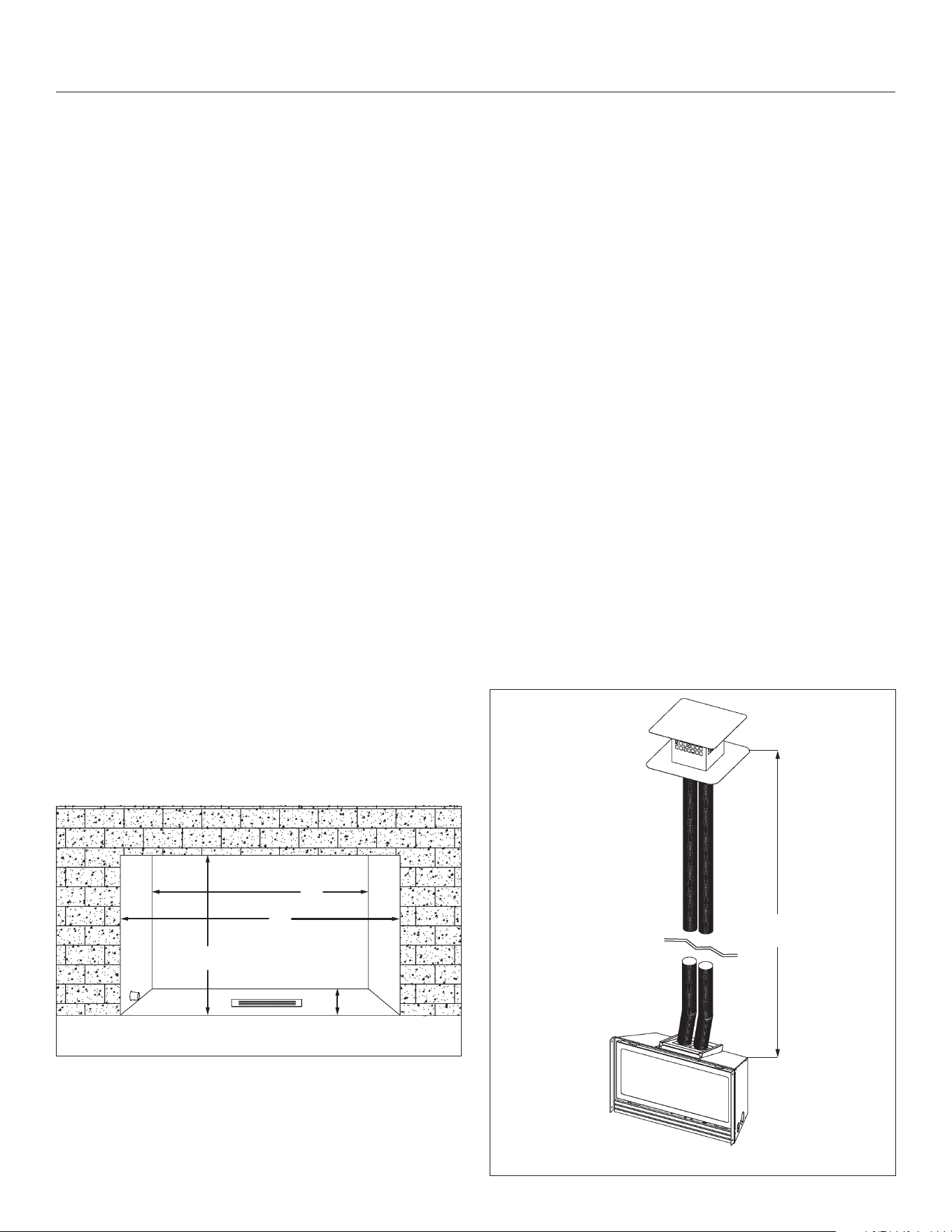
3.2.1 Existing Fireplace Opening
Minimum Requirements
(A) Height ............................................................................19-1/4” (489mm)
(B) Front Width ..................................................................29-1/2” (749mm)
(C) Depth .....................................................................................15” (381mm)
(D) Back Width ...................................................................18-7/8” (479mm)
3.2.2 Chimney Specications
WARNING: Any chimney clean-outs must t properly.
This replace insert is to be installed into a solid fuel masonry or
factory built non-combustible replace that has been installed in
accordance with the national, provincial, state, and local building
codes.
The existing chimney must be comprised of one of the following:
• Factory-built solid fuel chimney: 7” (178mm) minimum inside
diameter
• Masonry chimney: 6” x 8” (152mm x 203mm) minimum inside
diameter
Existing chimney height:
• Minimum: 10’ (3.05m) Maximum: 50’ (15.24m)
In certain circumstances where a chimney no longer terminates
through the roof line, a co-linear to co-axial adapter may be installed
where the existing chimney ends. After the adapter, the co-axial pipe
must maintain 1” (25mm) clearance to combustibles on all sides of the
vent pipe. Refer to Sections 4.2 (pg. 13) and 6.3 (pg. 16) for other
co-linear to co-axial conversion considerations and requirements.
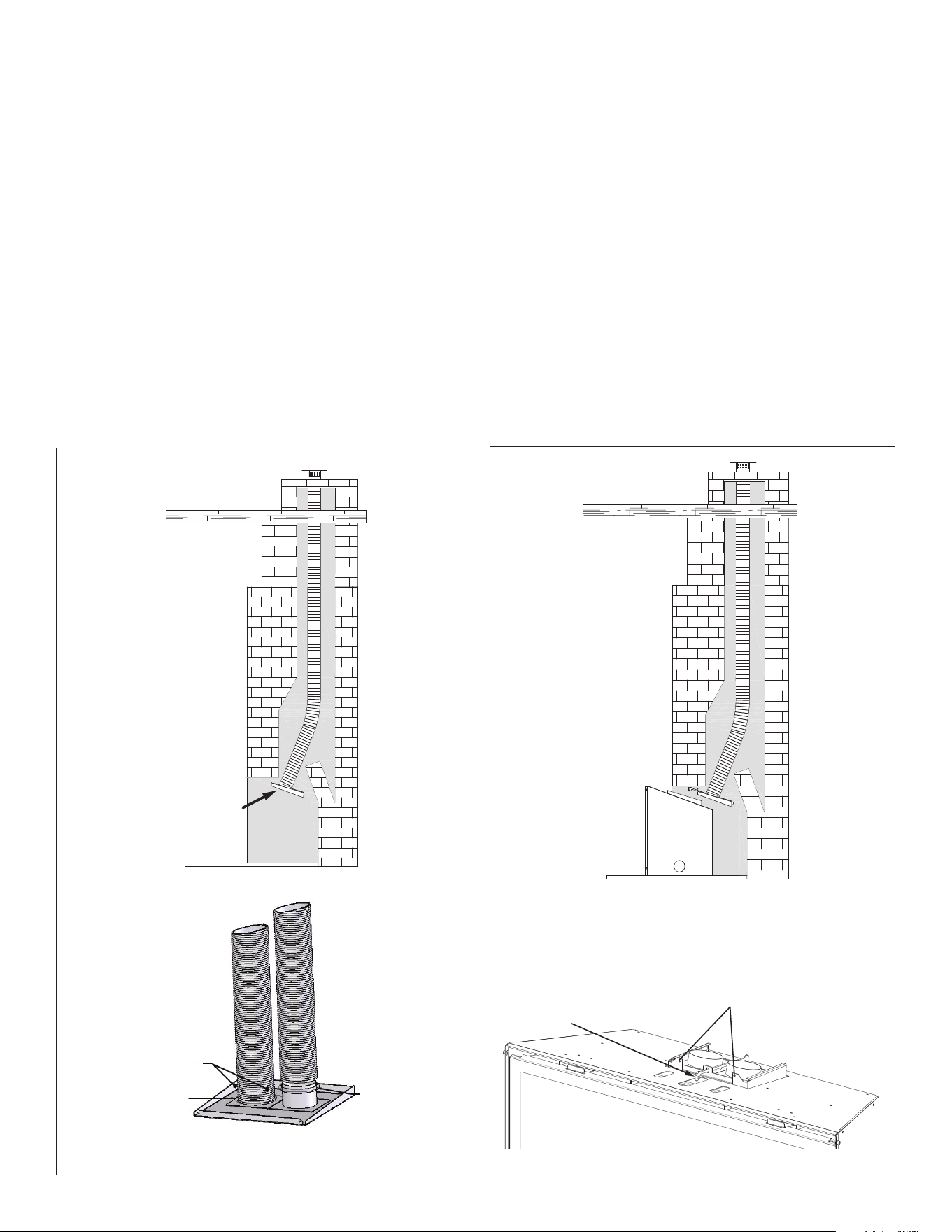
3.2.2.1 Determine Length of Existing Chimney
1. Remove and discard existing chimney cap.
2. NOTE: It is helpful to have two people complete this step.
Position one person at the replace opening and another person
at the top of the chimney.
3. Measure from the replace base to the top of the chimney.
4. Subtract the height of the insert from the previous
measurement.
5. This is the total length of the co-linear exible aluminum pipe
required for your installation. If using Kozy Heat #816, cut to
length.
Figure 3.1, Existing Opening Guide
C
A
B
D
Figure 3.2, Min/Max Chimney Length
MIN: 10 ft (3m)
MAX: 50 ft (15.24m)
#CSK-29-MV R.8 October 2019 Hussong Mfg. Co., Inc. • Kozy Heat Fireplaces TERMINATION LOCATION 13
4.0 TERMINATION LOCATION
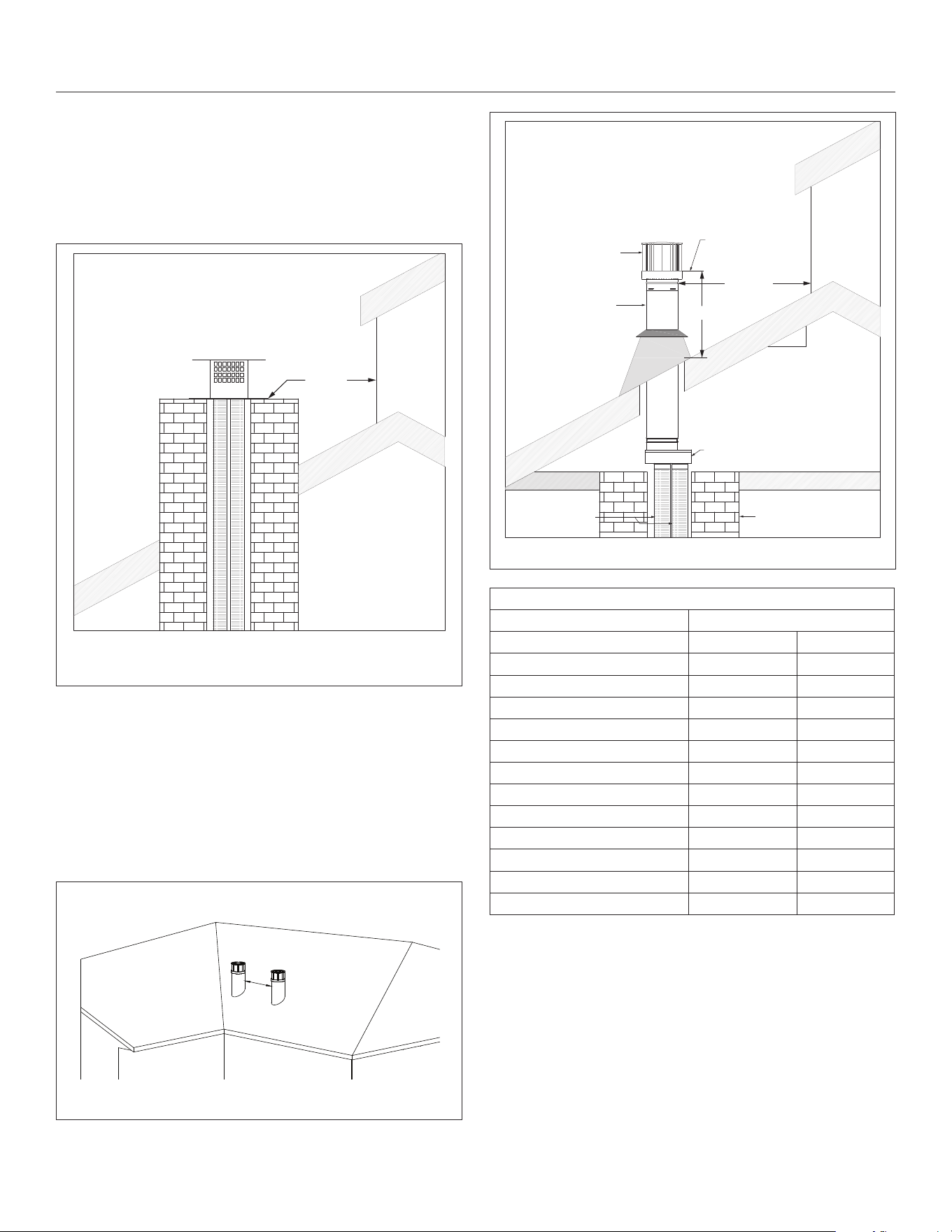
4.1 Chimney Vent Termination Clearances
WARNING: This appliance must not share or be connected to a chimney
ue serving any other appliance.
• Approved vent caps require 12” (305mm) clearance to
intersecting walls, overhangs or eaves as veried by test.
Figure 4.1, 3” x 3” Vent Cap Clearance through Existing Chimney
4.2 Co-linear to Co-axial Vent Terminations
WARNING: This appliance must not share or be connected to a chimney
ue serving any other appliance.
When combining co-linear and co-axial venting in a single venting
system using an approved 4” x 6-5/8” adapter, use Figure 4.2, Figure
4.3, and Table 4.1 for proper termination clearances.
Approved
Vent Cap
Minimum
12”
(305mm)
Clearance
Approved
Vent Cap
Approved 4” x 6
5⁄8”
Co-axial Vent Pipe
Lowest Discharge
Opening
H - Minimum Height from Roof to
Lowest Discharge Opening
Minimum
12” (305mm)
Co-linear to Co-axial Vent Adapter
Masonry Chimney
3” x 3” Flex Pipe
Roof Pitch = x/12
12
x
H
Clearance between two vertical terminations for US and Canadian installations
(may be same height)
12”
(305mm)
Figure 4.2, Clearance between two Vertical Terminations
Figure 4.3, Co-linear to Co-axial Vertical Termination Clearances
Table 4.1, Minimum Vertical Termination Height (use with Figure 4.3)
Minimum height (H) from roof
Roof Pitch Feet Meters
Flat to 6/12 1.0 0.30
Over 6/12 to 7/12 1.25 0.38
Over 7/12 to 8/12 1.5 0.46
Over 8/12 to 9/12 2.0 0.61
Over 9/12 to 10/12 2.5 0.76
Over 10/12 to 11/12 3.25 0.99
Over 11/12 to 12/12 4.0 1.22
Over 12/12 to 14/12 5.0 1.52
Over 14/12 to 16/12 6.0 1.83
Over 16/12 to 18/12 7.0 2.13
Over 18/12 to 20/12 7.5 2.27
Over 20/12 to 21/12 8.0 2.44

14 INSTALLATION PREPARATION Hussong Mfg. Co., Inc. • Kozy Heat Fireplaces #CSK-29-MV R.8 October 2019
5.0 INSTALLATION PREPARATION
NOTE: This gas replace insert is approved for installation in masonry
and factory-built solid fuel burning replaces.
ATTENTION: Any removed parts must be capable of re-installation if
this insert is ever removed. Removal of rivets or screws is acceptable.
5.1 Inspect and Clean Existing Chimney
• Verify existing chimney is constructed of non-combustible
material.
• Verify existing chimney is clean and in good working order. Clean
existing chimney and replace to prevent a creosote odor from
entering the home.
• Verify combustible mantel and sidewall clearances comply with
Section 8.0 on page 22.
• The refractory, glass doors, screen rails, screen mesh, and log
grates may be removed from existing replace before installing
this gas replace insert.
5.2 Flue Damper
• The replace ue damper can be fully blocked open, or removed
for installation of this gas replace insert. Remove existing
chimney cap.
5.3 Gas Line
• A gas line must be able to be installed to the insert.
• If the factory-built replace has no gas access hole(s) provided,
an access hole of 1½ in. (37.5 mm) or less may be drilled
through the lower sides or bottom of the rebox in a proper
workmanship like manner. The access hole must be plugged
with non-combustible insulation after the gas supply line has
been installed.
• Run gas line to the gas replace insert through the gas line hole
provided. The gas access hole is located on the right side of the
unit. Do not run gas line in a manner that would obstruct fan
operation.
• If the gas replace insert is to be installed into minimum opening
dimensions, the gas line may need to be run after appliance
placement due to space limitations.
5.4 Electrical Wiring
• Provisions must be made to provide electrical power for
appliance operation.
• See Figure 2.1 on page 9 for electrical outlet box location to
run any necessary electrical wiring to the gas replace insert.
5.5 Fireplace Conversion
• Mechanically attach the label with the following warning to at
the bottom existing rebox so it will be visible if this gas replace
insert is removed.
WARNING: This replace has been converted for use with a gas replace
insert only and cannot be used for burning wood or solid fuels unless
all original parts have been replaced, and the replace re-approved by
the Authority Having Jurisdiction.
#CSK-29-MV R.8 October 2019 Hussong Mfg. Co., Inc. • Kozy Heat Fireplaces INSTALLATION 15
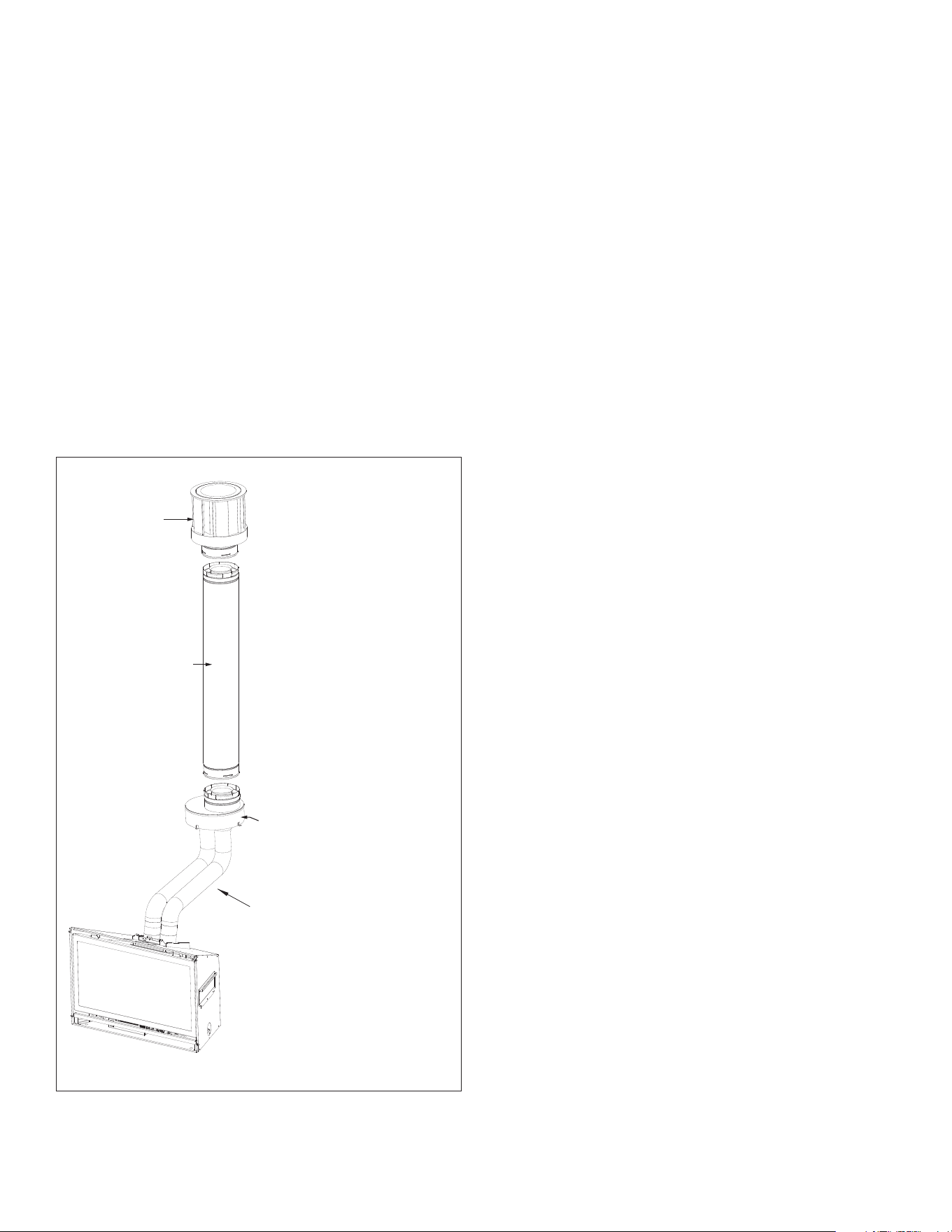
6.0 INSTALLATION
6.1 Approved Vent Systems
Kozy Heat #816 and #816-CAP
For use with minimum 6” x 8” I.D. masonry or 7” I.D. Class A metal
chimneys; includes one roll of 36’ (10.97 m) of expandable 3” exible pipe
and round termination cap.
Other approved vent manufacturers
BDM, American Metals (Amerivent), Metal Fab, Olympia Venting Supply,
Selkirk, Simpson Dura-Vent, and ICC.
This appliance is approved to combine co-linear and co-axial venting
in a single venting system using an approved 4” x 6-5/8” adapter.
Chimney specications (Section 3.2.2 on page 12) must be adhered
to when converting to co-linear to co-axial vent system. See section
6.3 Co-linear to Co-axial Combined Venting on page 16
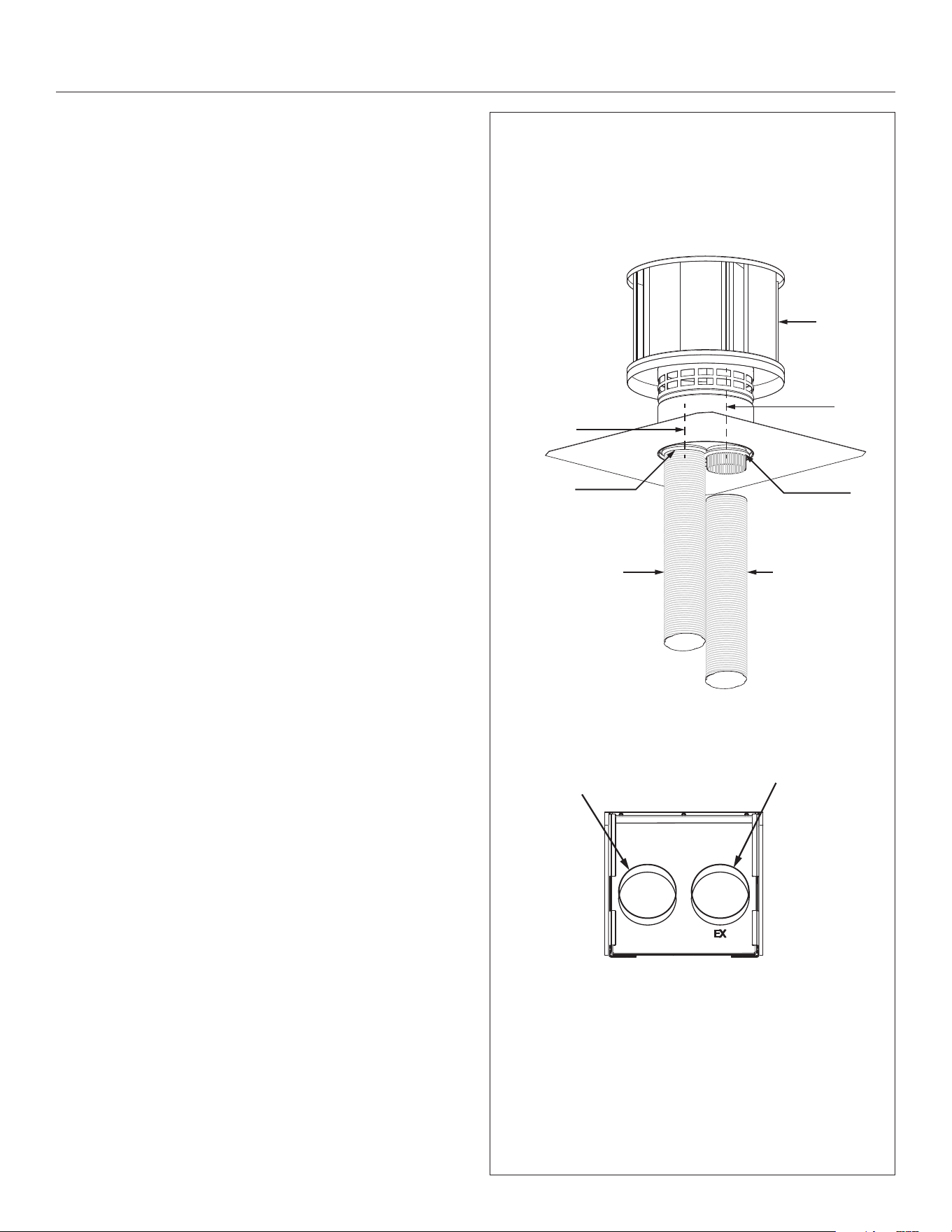
6.2 Kozy Heat #816 and #816-CAP
IMPORTANT: Proper operation of this insert requires the exhaust pipe
and combustion air pipe to be connected to their correct ue collar, on
both the termination kit and the gas replace insert vent adapter.
The replace insert exhaust ue collar is located on the right side.
Install termination cap with the exhaust ue collar on the right side.
NOTE: The exhaust pipe will have a red marking.
IMPORTANT: Maximum horizontal vent runs of 24 in (609 mm) require
a 1 in (25mm) rise per 12 in (305 mm) run. Care should be taken when
installing the exible vent pipes to avoid a tight bend that may cause
abrasion or damage to the exible pipes.
1. Measure the total chimney length required and cut #816 (36’
[10.97m] of 3” exible pipe) to the measured length.
2. Carefully extend the exhaust and combustion air intake pipes to
total chimney length required.
3. Slide the combustion air intake pipe (the end without a collar)
over termination cap collar (A). Secure to #816-CAP termination
cap (E) with (3) self-tapping screws (not provided).
4. Place a bead of sealant around the inner edge at the end of the
exhaust pipe (without collar / red marking) and slide onto the
corresponding labeled collar (B) on termination cap (E).
5. Secure the exhaust pipe to termination cap (E) with (3) self-
tapping screws (not provided). Apply additional sealant around
joint to ensure a proper seal.
6. Complete vent system installation by following the instructions
outlined in Sections 6.3 through 6.6.
COMBUSTION AIR
INTAKE 3” FLEX LINER
EXHAUST VENT
3” FLEX LINER
USES #816 36 ft (10.97m) EXPANDABLE 3” FLEXIBLE PIPE
C
A
B
D
C
#816 and #816-CAP
(A) Intake Collar (extends
through bottom plate)
(B) Exhaust Collar (extends
through middle divider
plate)
(C) Sealant (not provided)
(D) #816-CAP Termination Cap
VENT ADAPTER (TOP VIEW)
COMBUSTION AIR
INTAKE COLLAR (LEFT)
EXHAUST COLLAR (RIGHT)
Figure 6.1, #816-CAP
16 INSTALLATION Hussong Mfg. Co., Inc. • Kozy Heat Fireplaces #CSK-29-MV R.8 October 2019
6.3 Co-linear to Co-axial
Combined Venting
IMPORTANT: Maximum horizontal vent runs of 24” (609 mm) require
a 1” (25mm) rise per 12” (305 mm) run. Care should be taken when
installing the exible vent pipes to avoid a tight bend that may cause
abrasion or damage to the exible pipes.
After the co-linear to co-axial vent adapter, the co-axial pipe requires
a minimum of 1” (25mm) clearance to combustibles on all sides of the
rigid pipe.
• Maximum horizontal run of 3” x 3” exible pipe length: 24”
(610mm)
• Minimum total combination of co-linear and co-axial vent pipe:
10’ (3.05m)
• Maximum total combination of co-linear and co-axial vent pipe:
50’ (15.24m)
MAX HORIZONTAL RUN OF
3” x 3“ FLEX PIPE: 24” (610mm)
CO-LINEAR TO CO-AXIAL
VENT ADAPTER
4” x 6-5/8”
CO-AXIAL VENTING
TERMINATION
CAP
Figure 6.2, Co-linear to Co-axial Venting
#CSK-29-MV R.8 October 2019 Hussong Mfg. Co., Inc. • Kozy Heat Fireplaces INSTALLATION 17
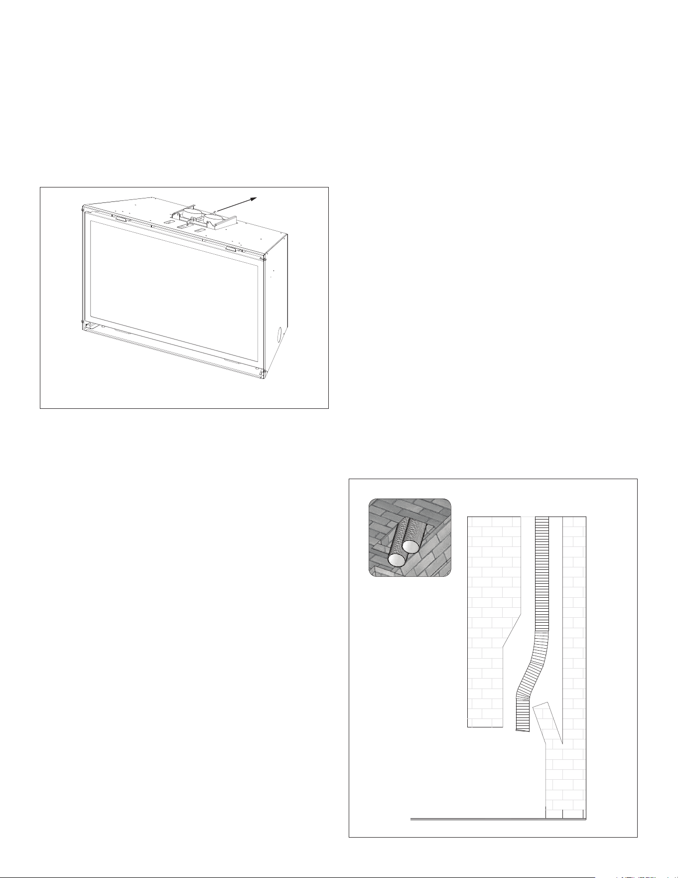
6.4 Remove Vent Adapter
ATTENTION: All information outlined in Section 5.0 on page 14 must
be completed before continuing with this installation.
1. Remove the vent adapter at the top of appliance by sliding
the vent adapter back out of channels. Refer to the following
instructions for vent system attachment to the vent adapter.
Figure 6.4, Chimney Vent Run
6.5 Run Vent System
NOTE: If osets are present in existing chimney, place a weighted rope
around the pipe ends to guide them through the chimney. DO NOT
ATTEMPT TO TIE ONE ROPE AROUND BOTH PIPES.
• To prevent cold air drafts, Hussong Manufacturing recommends
to insulate the 3” x 3” exible vent pipes and chimney using
unfaced insulation products listed as noncombustible per ASTM
E 136.
1. OPTIONAL: Before installing vent system down through the
chimney, place unfaced insulation around the rst 3 ft (914 mm)
of vent system below termination cap. Secure with wire.
2. Install the 3” x 3” exible pipes down through existing chimney.
Guide ropes (if used) to aid installation.
3. To secure chimney termination cap to chimney, apply a liberal
bead of sealant (provided) around the top of the chimney. Set
termination cap into position as instructed by vent system
manufacturer’s installation manual.
OPTIONAL Kozy Heat #816-CAP: Secure termination cap to
existing chimney with 2 in (50 mm) self-tapping screws and
anchor straps (not provided) through the pilot holes, located on
the sides of the termination cap.
4. From inside the existing replace, carefully pull ropes (if used) or
the exible pipes down until both exhaust pipe and combustion
air intake are into the existing replace rebox.
5. OPTIONAL: To prevent heat loss up chimney, place unfaced
insulation products listed as non-combustible per ASTM E 136
between the 3” x 3” exible vent pipes and chimney.
6.6 Connect Vent Pipe to Vent Adapter
Figure 6.3, Vent Adapter Removal
18 INSTALLATION Hussong Mfg. Co., Inc. • Kozy Heat Fireplaces #CSK-29-MV R.8 October 2019
6.7 Place and Secure Appliance
1. Slide the gas replace insert into existing replace opening until
the channels on top of the appliance are aligned with the vent
adapter.
2. Insert the vent adapter pull rod handle through access slot at
the top of appliance and place pull handle hook through the
hole in pull rod. Simultaneously push the gas insert into existing
replace and pull the vent adapter forward until seated.
3. Secure vent adapter to appliance by using slots at the top of the
appliance to secure with (2) ½ in (13 mm) sheet metal screws
(included in components packet).
4. Use the pull rod handle to pull the vent adapter back to starting
position. Remove pull handle. Verify vent system connection.
5. If necessary, level the gas insert by threading leveling bolts
(included in components packet) into nuts at the bottom of the
insert (2 each side). Verify appliance is properly positioned.
IMPORTANT: Proper operation of this insert requires the exhaust pipe
and combustion air pipe to be connected to their correct ue collar, on
both the termination kit and the gas replace insert vent adapter.
1. Place previously removed vent adapter into existing replace
opening.
2. Connect exhaust vent pipe (red marking) to exhaust collar
on vent adapter. Apply a bead of sealant (provided) around
exhaust pipe and slide inside collar marked ‘Exhaust.’ Secure with
provided (3) ½ in (13 mm) self-tapping screws. Apply additional
sealant around join to ensure an air tight seal.
3. Connect air intake vent pipe to intake collar on vent adapter.
Apply a liberal bead of sealant around intake collar on vent
adapter. Slide combustion intake pipe over the collar and secure
with provided (3) ½ in (13 mm) self-tapping screws. Apply
additional sealant around joint to ensure an air tight seal.
4. Visually check vent pipe connection to vent adapter.
ALIGNED
GAS INSERT
Figure 6.5, Vent Pipe Connection to Vent Adapter
VENT ADAPTER
FLEXIBLE PIPES
SHEET METAL
SCREWS (3 TOTAL)
SEALANT
SEALANT
Figure 6.6, Aligned Insert
SECURE WITH (2) SCREWS
PULL ROD
Figure 6.7, Seated Vent Adapter
#CSK-29-MV R.8 October 2019 Hussong Mfg. Co., Inc. • Kozy Heat Fireplaces INSTALLATION 19
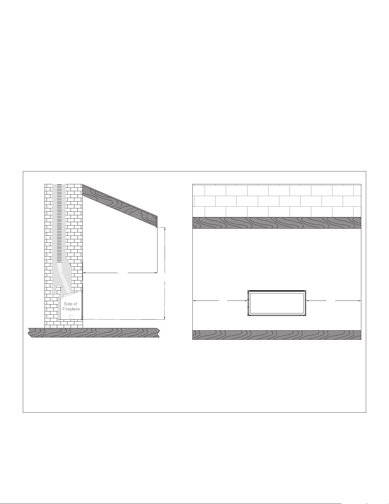
6.8 Outdoor Covered Fireplace Installation
An outdoor covered replace installation allows a replace to be
installed in an outdoor covered area, where the appliance is protected
from direct precipitation.
Follow the instructions and illustrations for installation procedures.
Drawings are for reference only and your replace may look dierent
than shown.
6.8.1 Safety Screen Barriers
Hussong Mfg. highly recommends to use black painted safety barriers
in outdoor installations. Other screen barriers that incorporate
a plated or patina nish are highly susceptible to oxidation and
discoloration.
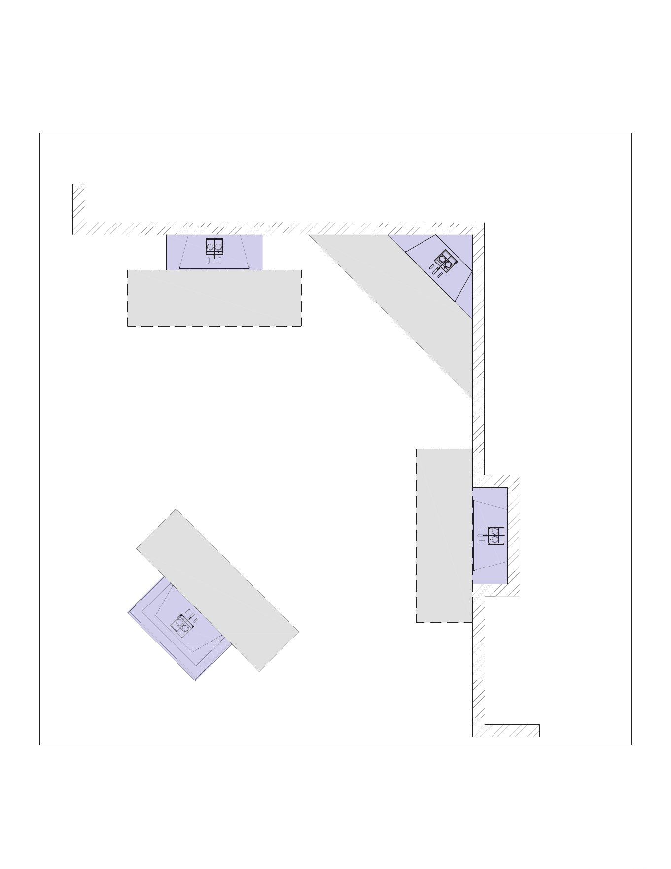
6.8.2 Requirements
• The continuous insulated building envelope and weatherproof
membrane are not to be interrupted by replace installation. See
Figure 6.9 on the following page.
• Fireplace operation is approved from 40°F to 110°F.
• All wiring connections shall be in accordance with outdoor
requirements of NECA NFPA 70.
• All clearances and requirements in this manual must be adhered
to.
FRONT OF
FIREPLACE
A
B
CC
The width of the overhang to each side of the
appliance (C) must be a minimum of 1/2 or
greater of the rooine elevation (B) above the
base of the replace.
The overhang (A) must be a minimum of 1/2 or
greater of the rooine elevation (B) above the base
of the replace.
EXAMPLE: If rooine (B) is 10 ft above the base of replace, the overhang (A) must be 5 ft
or greater. The width of the overhang to EACH side of the replace (C) must be 5 ft or greater.
Figure 6.8, Outdoor Covered Fireplace Installation
20 INSTALLATION Hussong Mfg. Co., Inc. • Kozy Heat Fireplaces #CSK-29-MV R.8 October 2019
6.8.3 Outdoor Covered Fireplace Installation (continued)
Figure 6.9, Outdoor Covered Installation 2
Continuous insulated building
envelope and weatherproof
membrane are not interrupted by
replace installation
Minimum weatherproof
overhang in front and sides
Free standing structure
(weatherproof enclosure)
Minimum weatherproof
overhang in front and sides
Minimum weatherproof
overhang in front and sides
Minimum weatherproof
overhang in front and sides
INSIDE
OUTSIDE
INSIDE
#CSK-29-MV R.8 October 2019 Hussong Mfg. Co., Inc. • Kozy Heat Fireplaces GAS LINE CONNECTION 21
7.0 GAS LINE CONNECTION
7.1 Gas Conversion (sold separately)
ATTENTION: The conversion shall be carried out in accordance with the
requirements of the provincial authorities having jurisdiction and in
accordance with the requirements of the ANSI Z223.1 installation code.
This replace is manufactured for use with natural gas. Follow the
instructions included with the conversion kit if converting to Propane.
7.2 Gas Line Installation
CAUTION: Installation of the gas line must only be done by a qualied
person in accordance with local building codes, if any. If not, follow
ANSI 223.1. Commonwealth of Massachusetts installations must be
done by a licensed plumber or gas tter.
NOTE: The appliance and its individual shuto valve must be
disconnected from the gas supply piping system during any pressure
testing of that system at pressures in excess of ½ psi (3.5 kPa). For test
pressures equal to or less than ½ psi (3.5 kPa), the appliance must be
isolated from the gas supply piping system by closing its individual
manual shut-o valve.
• A listed (and Commonwealth of Massachusetts approved) ½
in. (13 mm) tee handle manual shut-o valve and exible gas
connector are to be connected to the ½ in. (13 mm) control valve
inlet. If substituting for these components, please consult local
codes for compliance.
• If installing this insert into minimum opening dimensions,
the gas line may need to be run after placement due to space
limitations. See Section 3.2 Existing Fireplace Specications on
page 19.
• This replace is equipped with a 3/8” (10 mm) x 18” (457 mm)
long exible gas connector and manual shut-o valve.
• Run gas line into replace, preferably through right gas line hole
provided. The gas line should be run to the point of connection
where the shut-o valve and exible gas line will connect.
• Do not run gas line in a manner that would obstruct fan
operation.
• For high altitude installations, consult the local gas distributor or
the authority having jurisdiction for proper rating methods.
Table 7.1, Inlet Gas Supply Pressures
Fuel Minimum Pressure Maximum Pressure
Natural Gas 5” WC (1.25 kPa) 10.5” WC (2.62 kPa)
Propane 11” WC (2.74 kPa) 13” WC (3.24 kPa)

22 FACING AND FINISHING Hussong Mfg. Co., Inc. • Kozy Heat Fireplaces #CSK-29-MV R.8 October 2019
8.0 FACING AND FINISHING
8.1 Facing and Finishing Requirements
IMPORTANT: Adequate accessibility clearances for servicing and
proper operation must be maintained.
8.1.1 Adjacent Sidewall Requirements
• The adjacent sidewall minimum clearance is 6” (152mm) from
the appliance sides (Fig 8.1).
8.1.2 Clearance to Ceiling
• As shown in Figures 8.1 and 8.4, the minimum clearance from the
replace enclosure oor to the ceiling is 55” (1.04m).
8.1.3 Mantel Requirements
WARNING: All minimum clearances to combustible material MUST be
maintained.
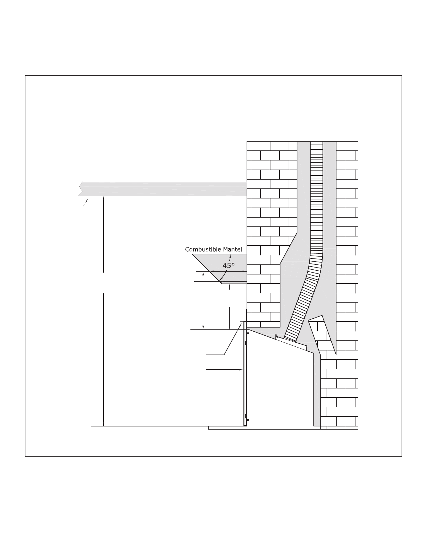
• Combustible Mantel Projections - As referenced in Figure 8.2, the
9” (229mm) mantel can start at 16” (254mm) above the top of the
appliance. Mantel projections can increase 1” (25mm) of depth
for every 1” (25mm) of height starting at the 9” (229mm) mantel.
• CK29-LMK Mantel Projections (FOR USE ONLY with safety barriers
#CK29-RSF & #CK29-PSF) - As referenced in Figure 8.4, the 6”
(152mm) mantel can start at 11” (279mm) above the top of
the appliance only when the low mantel kit is installed. Mantel
projections can increase 1” (25mm) of depth for every 1” (25mm)
of height starting at the 6” (152mm) mantel
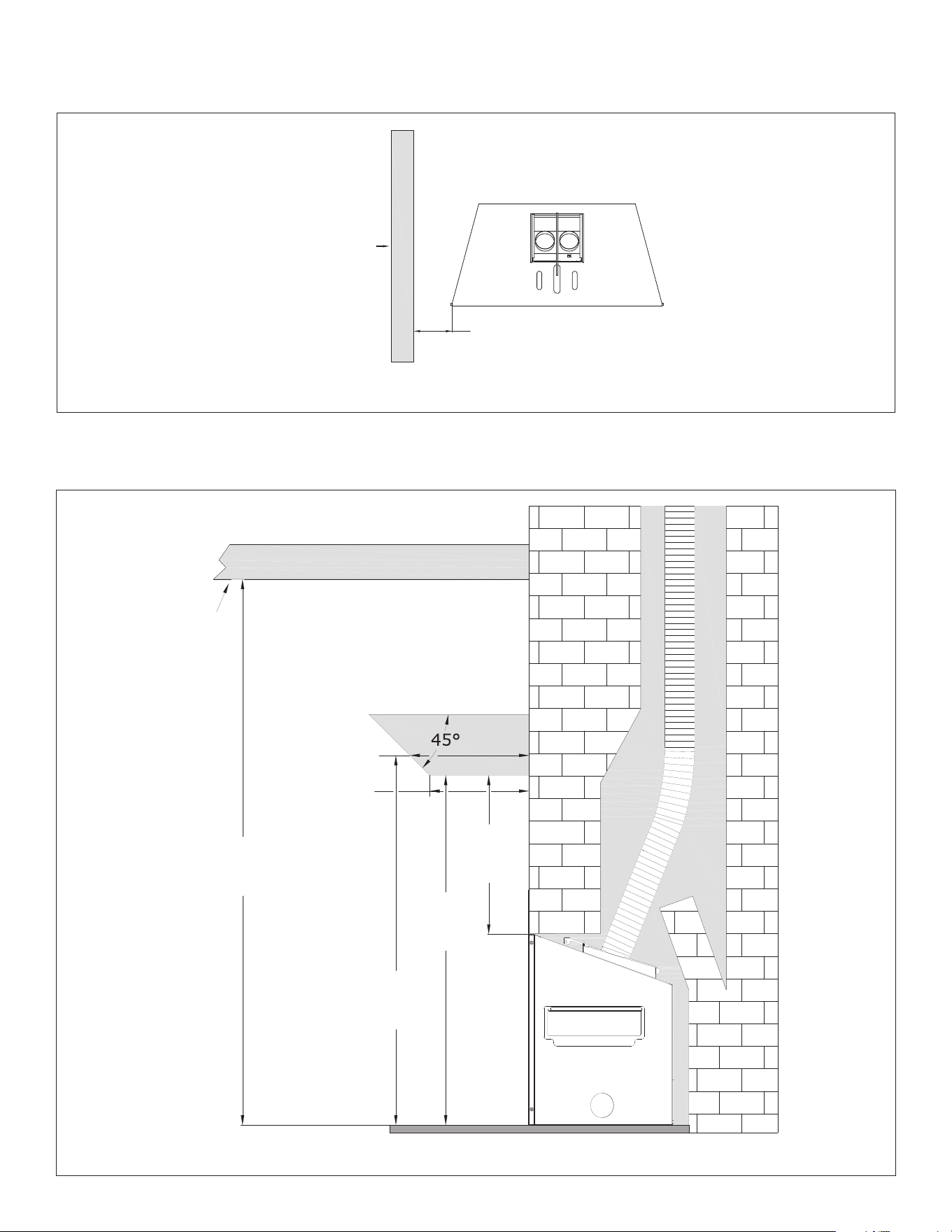
#CSK-29-MV R.8 October 2019 Hussong Mfg. Co., Inc. • Kozy Heat Fireplaces FACING AND FINISHING 23
COMBUSTIBLE
MATERIAL
6” (152mm) CLEARANCE
TO ADJACENT SIDEWALL
Combustible Floor - can be in front and underneath unit
55”
(1.40m)
11” (305mm)
9” (254mm)
16”
(407mm)
35
¼”
(895mm)
37
¼”
(946mm)
CEILING
COMBUSTIBLE MANTEL
Figure 8.1, Clearance to Adjacent Sidewall
Figure 8.2, Mantel Requirements
24 FACING AND FINISHING Hussong Mfg. Co., Inc. • Kozy Heat Fireplaces #CSK-29-MV R.8 October 2019
8.2 #CK29-LMK Low Mantel Kit
This low mantel kit is for use only with safety barriers CK29-PSF and
CK29-RSF. Follow the drawing below for assembly and installation.
REMOVE (2) SCREWS AS SHOWN LOCATED AT THE BACK
OF THE SCREEN FRONT AND ALIGN THE HEAT DEFLECTOR
POSITION THE HEAT DEFLECTOR BY SLIDING IT
UNDER THE MOUNTING TABS AS SHOWN
REPLACE (2) SCREWS THROUGH THE HOLES IN
THE MOUNTING TAB AND HEAT DEFLECTOR
GASKET MUST BE IN CONTACT
WITH SHROUD
CK29-RSF (SHOWN)
HEAT DEFLECTOR
Figure 8.3, #CK29-LMK Assembly and Installation
#CSK-29-MV R.8 October 2019 Hussong Mfg. Co., Inc. • Kozy Heat Fireplaces FACING AND FINISHING 25
8.2.1 Low Mantel Kit Clearances
55”
(1.40m)
9” (229mm)
6” (152mm)
14”
(356mm)
11”
(279mm)
CEILING
CK29-PSF, CK29-RSF WITH
LOW CLEARANCE MANTEL
KIT INSTALLED
HEAT DEFLECTOR
IF USING CK29-PSF, CK29-RSF SAFETY BARRIER WITH
LOW MANTEL KIT INSTALLED,
THESE LOWER MANTEL CLEARANCES ARE ALLOWED
Figure 8.4, #CK29-LMK Mantel Clearances with #CK29-PSF or #CK29-RSF installed
26 FACING AND FINISHING Hussong Mfg. Co., Inc. • Kozy Heat Fireplaces #CSK-29-MV R.8 October 2019
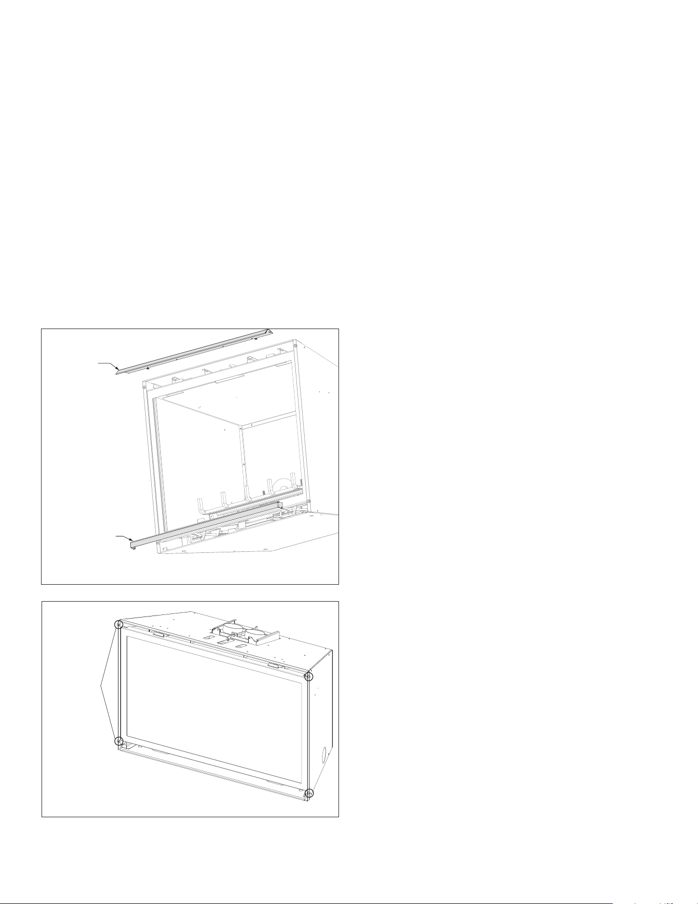
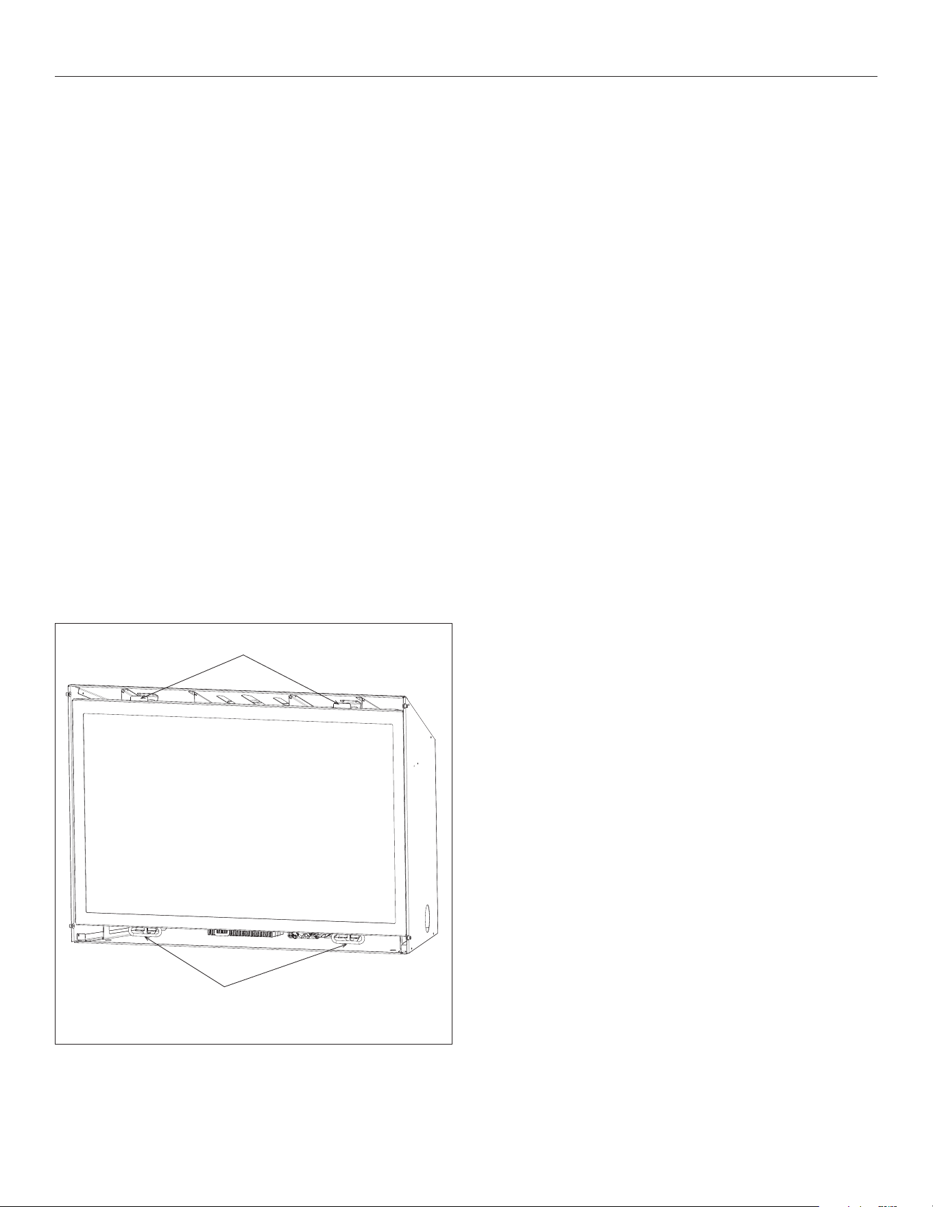
8.3 Shroud Installation
CAUTION: Trim panels or surrounds must not seal ventilation
openings in existing replace that this appliance is installed in.
Draft relief openings must not be covered or blocked.
WARNING: The ow of combustion and ventilation air must not be
obstructed.
1. Remove the upper louver by lifting up and out of the mounting
anges.
2. Remove lower louver by lifting the louver out of the slots on the
mounting bracket.
3. Remove the glass assembly.
4. Align the mounting holes on the shroud to the corresponding
mounting nuts on the sides of the insert metal cabinet.
5. Secure with (4) truss head screws (provided).
6. Reinstall all components previously removed.
Figure 8.5, Upper Louver and Lower Louver Removal
MOUNTING
NUTS
(2 EACH SIDE)
Figure 8.6, Mounting Nuts Location
UPPER LOUVER
LOWER LOUVER
8.4 Safety Barrier Installation
1. Locate the (4) slots on the shroud (2 each side).
2. Align the tabs located on the back of the safety barrier with the
slots on the shroud.
3. Raise the safety barrier slightly into the slots and allow the tabs
to lower into position.
• To remove safety screen: lift the screen up and out of slots.
#CSK-29-MV R.8 October 2019 Hussong Mfg. Co., Inc. • Kozy Heat Fireplaces GAS FIREPLACE INSERT SETUP 27
9.0 GAS FIREPLACE INSERT SETUP
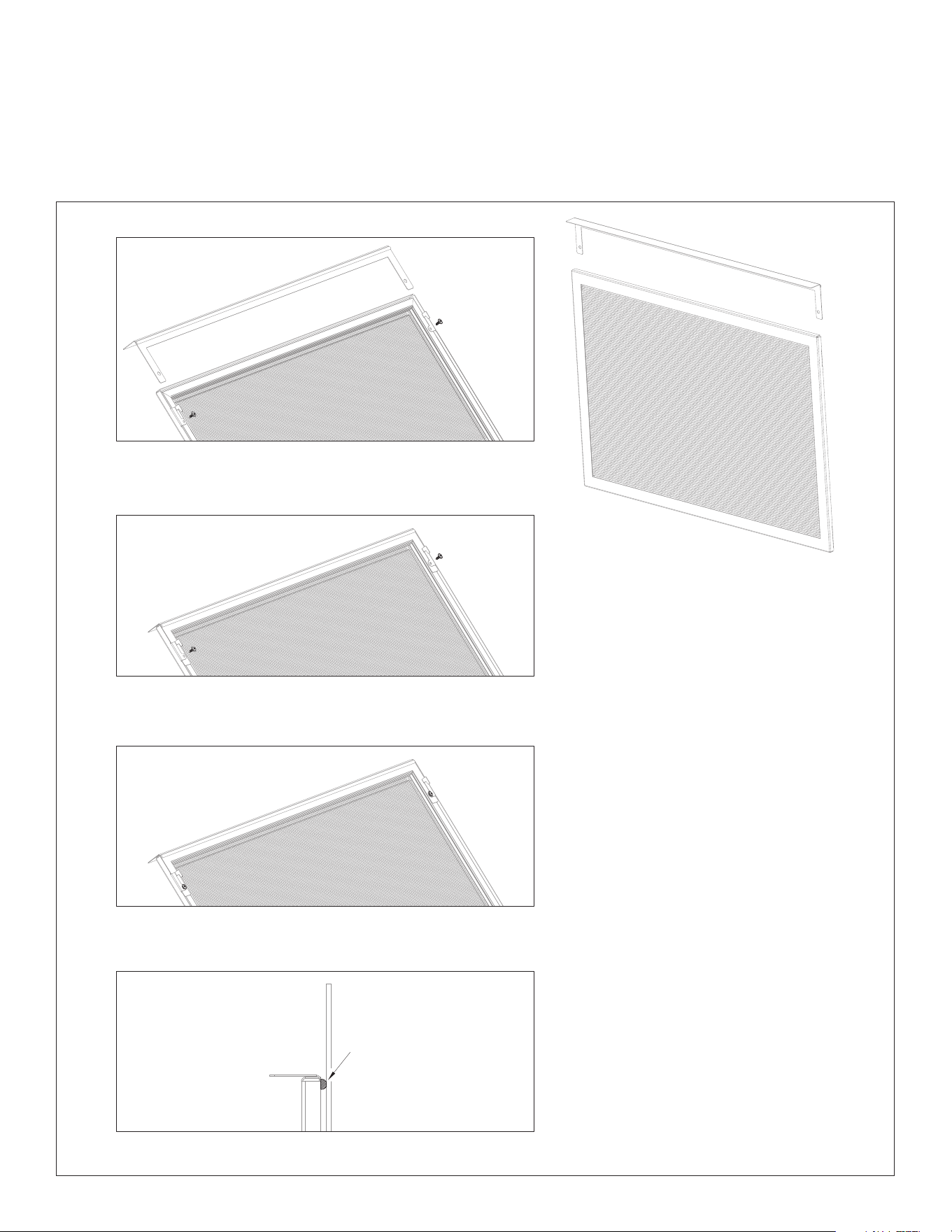
9.1 Glass Assembly
WARNING: Do not operate this replace with the glass removed,
cracked, or broken. Replacement of the glass assembly should be done
by a licensed or qualied service person.
9.1.1 Remove Glass Assembly
WARNING: Do not remove the glass assembly when hot.
1. Remove safety barrier.
1. Locate (2) spring-loaded latches securing the glass assembly at
the bottom of the rebox.
2. Pull the spring-loaded latches out and down to release the
bottom of the glass assembly.
3. Lift glass assembly up and o of the (2) tabs located at the top of
the rebox.
9.1.2 Install Glass Assembly
1. Align the slots on top of the glass assembly over the tabs at
the top of the rebox while lowering the bottom of the glass
assembly into position.
2. Pull the spring-loaded latches out and up to secure the bottom
of glass to the bottom of the replace.
3. Reinstall safety barrier.
Figure 9.1, Glass Frame Assembly Installation and Removal
TABS
SPRING-LOADED LATCHES
28 GAS FIREPLACE INSERT SETUP Hussong Mfg. Co., Inc. • Kozy Heat Fireplaces #CSK-29-MV R.8 October 2019
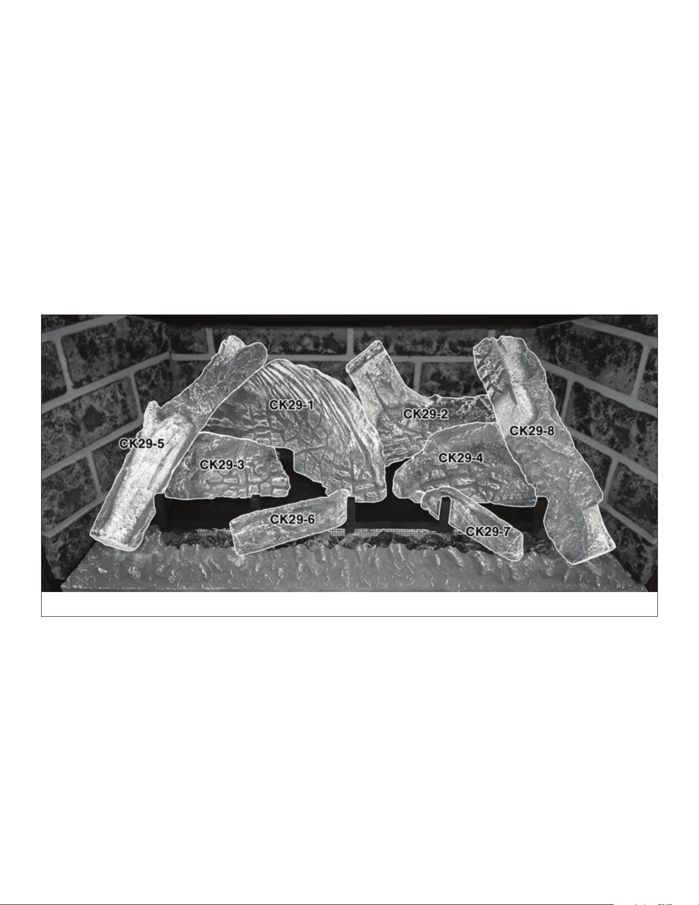
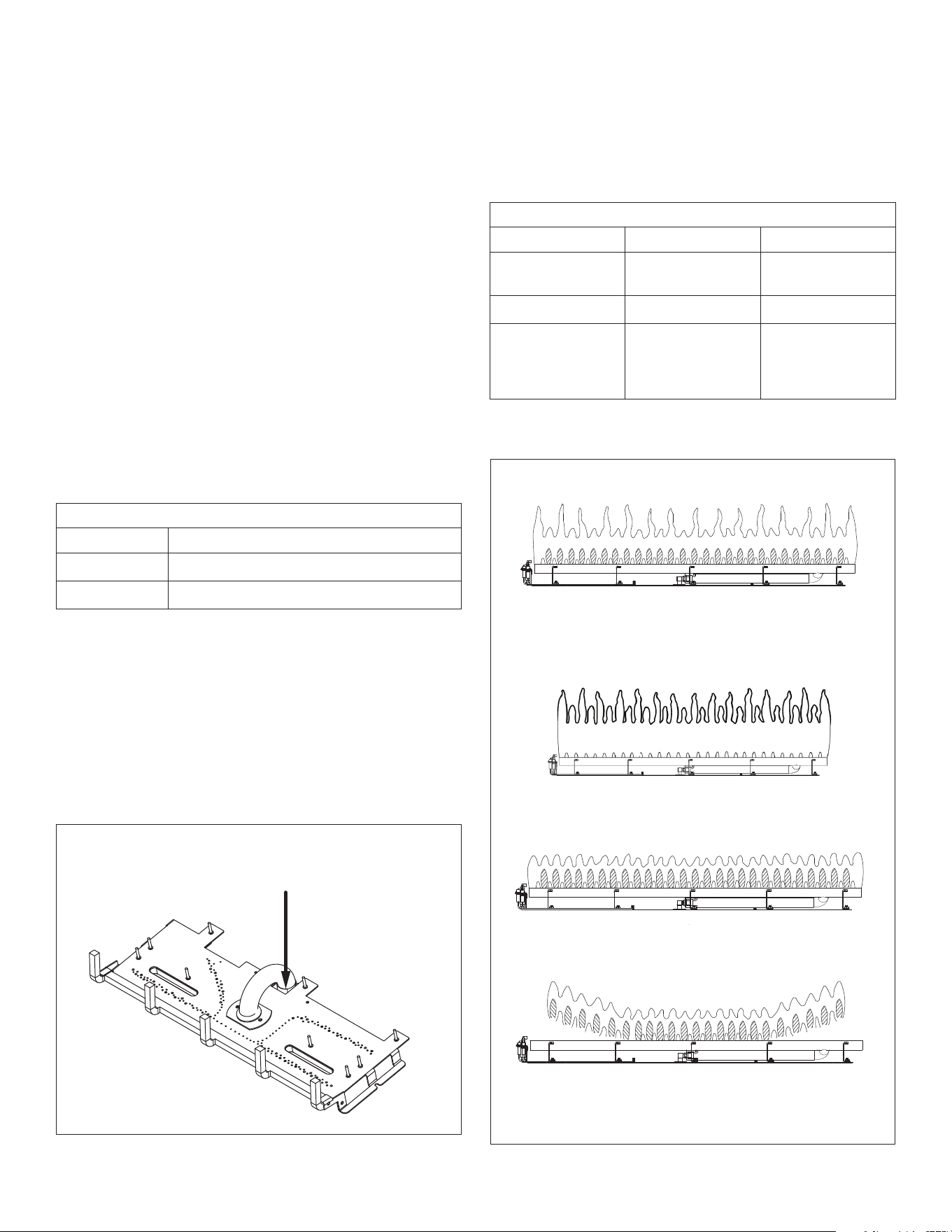
9.2 #CK29-500 Log Set Installation
CAUTION: Do not place logs directly over burner port holes. Improper
log placement may aect ame appearance and may cause excessive
soot to build upon the glass.
• If converting to propane, complete the conversion before
installing the log set. Follow the conversion instructions included
with the kit.
• Log numbers located on the bottom of each log. Refer to
following instructions and illustrations for proper placement.
1. Position the ember panel in front of the burner as shown.
2. Align the holes in base logs CK29-1, CK29-2, CK29-3, and CK29-4
with the corresponding mounting pins on the burner. Push the
logs down onto pins to seat.
3. Align logs CK29-5 and CK29-8 with corresponding notches on
the base logs and the ember panel.
4. Align the notches in logs CK29-6 and CK29-7 with the log grates
on the burner.
5. Distribute rockwool embers onto logs and burner.
Figure 9.2, Installation of CK29-500
#CSK-29-MV R.8 October 2019 Hussong Mfg. Co., Inc. • Kozy Heat Fireplaces GAS FIREPLACE INSERT SETUP 29
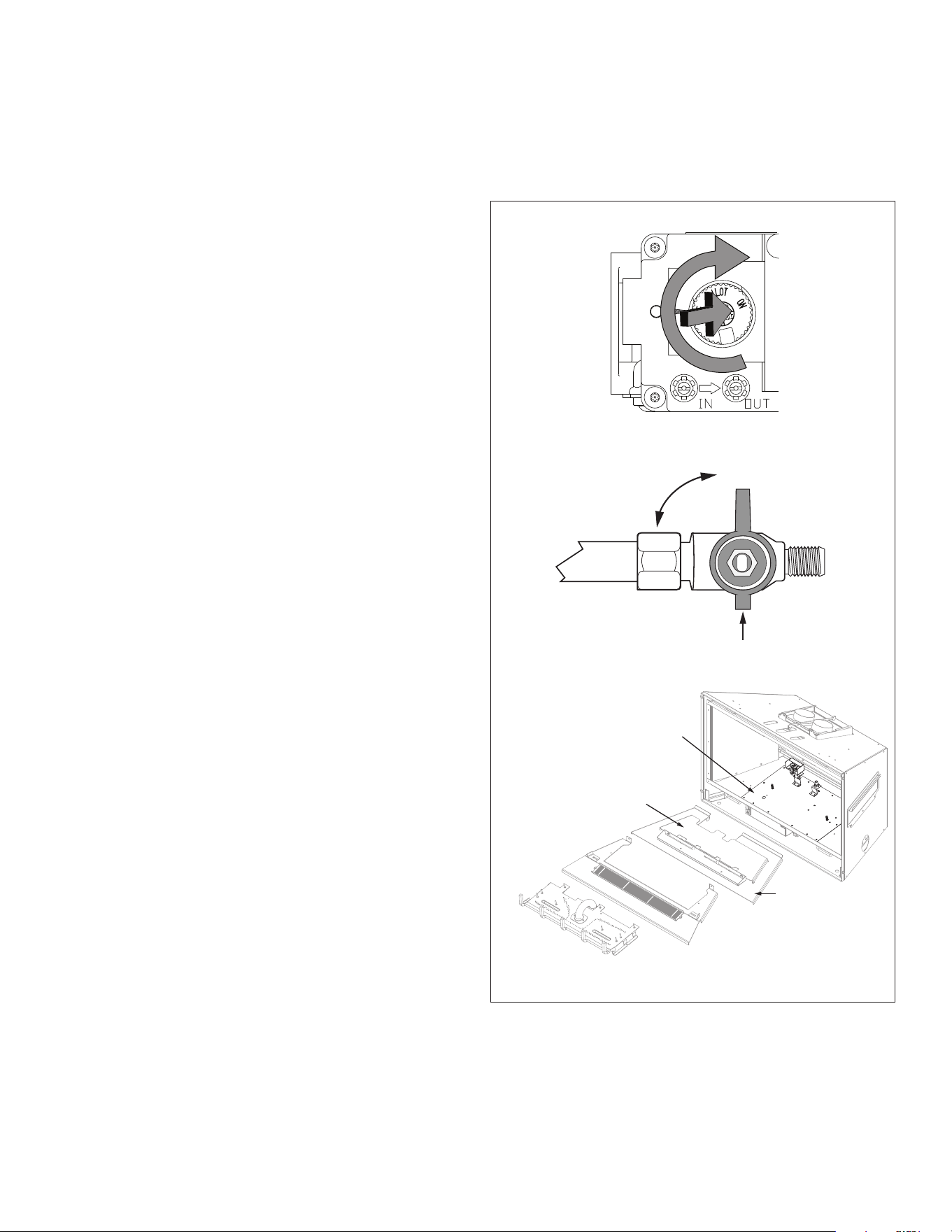
9.3 Control Board Removal and Installation
WARNING: If burner and/or pilot have been burning, use appropriate
protection to avoid burns or damage to personal property before
removing any components. DO NOT OPERATE THIS APPLIANCE
WITHOUT THE SEALING GASKET (LOCATED UNDER THE CONTROL
BOARD) IN PLACE. IF GASKETING IS DAMAGED, IT MUST BE REPLACED.
CAUTION: Check all connections for leaks with soapy water, whether
eld or factory made.
9.3.1 Control Board Removal
1. Remove the safety barrier.
2. Turn the replace o.
3. Locate the manual valve installed by your qualied service
technician. Turn the manual valve clockwise to the OFF position.
4. Disconnect any wall switch, remote control, or thermostat from
the top and bottom terminals on the gas valve, OR unplug all
components from receptacle and disconnect all wiring harnesses
attached to the gas valve.
5. Remove the glass frame assembly and log set.
6. Remove the burner assembly, secured with (2) screws.
7. Remove refractory panels (if installed).
8. Remove burner, secured with (2) screws at the back of the
rebox.
9. Remove the primary and secondary burner heat shields.
10. Remove (10) screws securing control board. Remove the control
board.
9.3.2 Control Board Installation
1. with mounting studs at the bottom of the rebox.
VERIFY SEALING GASKET IS IN PLACE ON THE BOTTOM OF THE
FIREBOX. Secure with screws previously removed.
2. Secure the control board with screws previously removed.
3. Reinstall the burner heat shields by placing the primary burner
heat shield on top of the control board. Position the cut-outs
over pilot assembly and burner orice, centering from side-to-
side and as far back as possible.
4. Reinstall burner (2) screws.
5. Reinstall refractory panels (if used).
6. Reinstall burner assembly. Verify the burner tube is positioned
over burner orice. Secure with (2) screws previously removed.
7. Reinstall log set.
8. Reconnect any wall switch, remote control, or thermostat wires
to the top and bottom terminals on the gas valve, OR reconnect
all wiring harnesses to the gas valve. Plug all components into an
electrical outlet.
9. Reinstall the glass frame assembly and safety barrier.
10. Turn the manual valve counter clockwise to the ON position.
11. Verify proper log placement, operation of replace, and any
electrical components.
ON
OFF
Figure 9.3, Control Board Removal and Installation
BURNER
ASSEMBLY
BURNER
CONTROL BOARD
SECONDARY BURNER
HEAT SHIELD
PRIMARY BURNER
HEAT SHIELD

30 ELECTRICAL INFORMATION Hussong Mfg. Co., Inc. • Kozy Heat Fireplaces #CSK-29-MV R.8 October 2019
10.0 ELECTRICAL INFORMATION
WARNING: Do not use this replace if any part has been under water.
Immediately call a qualied service technician to inspect this appliance
and to replace any part of the control system and any gas control which
has been under water.
WARNING - Electrical Grounding Instructions: This appliance is
equipped with a three-prong (grounding) plug for your protection
against shock hazard and should be plugged directly into a properly
grounded three-prong receptacle. Do not cut or remove the grounding
prong from this plug.
10.1 Electrical Specications
WARNING: AN OPTIONAL COMPONENT CONNECTION IS FOR LOW
VOLTAGE BATTERY OR DIRECT CURRENT ONLY. DO NOT CONNECT TO
120 OR 240 VOLTS AC.
This appliance, when installed, must be electrically grounded in
accordance with local codes, or in the absence of local codes, with
the National Electrical Code, ANSI/NFPA 70, or the Canadian Electrical
Code, CSA C22.1.
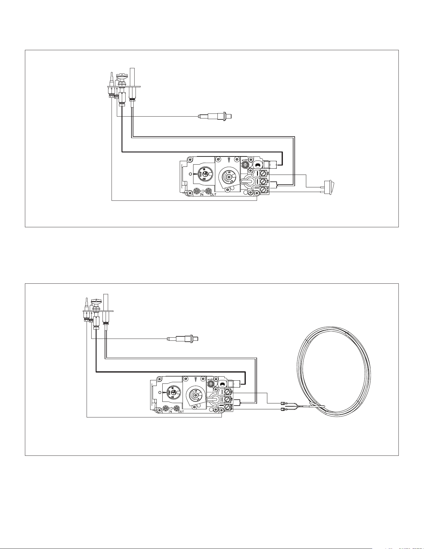
10.2 Wiring Requirements
CAUTION: Do connect high voltage (115V) wire to the gas valve.
• The millivolt gas valve system does not require 110-120 VAC
supply to operate.
• If desired, a thermostat or a wall switch may be installed for main
burner operational control using low-voltage wires. A thermostat
wire assembly is not included with this appliance.
• It is optional to disable rocker switch operating the main burner
by disconnecting the wires from the back of the gas valve (Figure
10.1).
• If the rocker switch wires are not disconnected, the ON/OFF
rocker switch must be in the OFF position for proper operation
of optional controls. If the ON/OFF rocker switch is ON, the main
burner will operate until it is turned OFF by the rocker switch.
The thermostat/wall switch components will not turn the main
burner o if the main burner has been turned on by the rocker
switch.
• If a the wall-mounted ON/OFF control or thermostat is to be
used, mount it in a convenient location on a wall near the
replace. Follow instructions included with assembly.
• If an optional component is to be used, run low-voltage wires
from gas valve to the location of component.
#CSK-29-MV R.8 October 2019 Hussong Mfg. Co., Inc. • Kozy Heat Fireplaces ELECTRICAL INFORMATION 31
THERMOCOUPLE
THERMOPILE
PILOT
PIEZO
ON/OFF
ROCKER SWITCH
THERMOCOUPLE
THERMOPILE
PILOT
PIEZO
WIRE ASSEMBLY
(not included)
Attach gas valve connectors to the wall switch/thermostat wires,
connect to top and bottom terminals marked TH and TP-TH on gas valve
Figure 10.1, Millivolt Gas Valve Wiring Schematic with ON/OFF Rocker Switch
Figure 10.2, Millivolt Gas Valve Wiring Schematic with Thermostat or Wall Switch Wiring
32 OPERATING INSTRUCTIONS Hussong Mfg. Co., Inc. • Kozy Heat Fireplaces #CSK-29-MV R.8 October 2019
11.0 OPERATING INSTRUCTIONS
• When this replace is initially lit, condensation will appear on the
glass. This is normal in all gas replaces and will disappear after
several minutes.
• A paint smell will occur during the rst few hours of burning. It
is recommended to leave the fan o during this period to help
speed the paint curing process.
• This replace may produce noises of varying degree as it heats
and cools due to metal expansion and contraction. This is normal,
and does not aect the performance or longevity of the replace.
FOR YOUR SAFETY READ BEFORE LIGHTING
WARNING
Do not operate appliance with the glass front removed, cracked, or
broken. Replacement of the glass should be done by a licensed or
qualied service person.
Under no circumstances should any solid fuel (wood, coal, paper,
cardboard, etcetera) be used in this appliance.
Children and adults should be alerted to the hazards of high surface
temperature and should stay away to avoid burns or clothing ignition.
CAUTION
Clothing or other ammable material should not be placed on or near
the appliance.
Young children should be carefully supervised when they are in the
same room as the appliance. Toddlers, young children and others
may be susceptible to accidental contact burns. A physical barrier is
recommended if there are at risk individuals in the house. To restrict
access to a replace or stove, install an adjustable safety gate to keep
toddlers, young children and other at risk individuals out of the room
and away from hot surfaces.
WARNING: If you do not follow these instructions exactly, a re or explosion may result causing property damage, personal injury,
or loss of life.
A. This appliance has a pilot which must be lighted by hand. When
lighting the pilot, follow these instructions exactly.
B. BEFORE LIGHTING smell around the appliance area for gas. Be
sure to smell next to the oor because some gas is heavier than
air and will settle on the oor.
WHAT TO DO IF YOU SMELL GAS
• Do not try to light any appliance.
• Do not touch any electric switch; do not use any phone in
your building.
• Immediately call your gas supplier from a neighbor’s phone.
Follow the gas supplier’s instructions.
• If you cannot reach your gas supplier, call the re
department.
C. Use only your hand to push in or turn the gas control knob.
Never use tools. If the knob will not push in or turn by hand,
don’t try to repair it, call a qualied service technician. Force or
attempted repair may result in a re or explosion.
D. Do not use this appliance if any part has been under water.
Immediately call a qualied service technician to inspect the
appliance and to replace any part of the control system and
any gas control that has been under water.
LIGHTING INSTRUCTIONS
1. STOP! Read all the safety information above on this page.
2. Set thermostat to lowest setting (if applicable).
3. Turn o all electric power to the appliance.
4. Open the control compartment access panel to access gas
controls.
5. Push in gas control knob slightly and turn clockwise to
“OFF”.
NOTE: Knob cannot be turned from “PILOT” to “OFF” unless
knob is pushed in slightly. Do not force.
6. Wait ve (5) minutes to clear out any gas. Then, smell
for gas, including near the oor. If you smell gas, STOP!
Follow ‘B’ in the safety information above. If you do not smell
gas, go to the next step.
7. Locate pilot - follow metal tube from gas control. The pilot is
located inside the combustion chamber.
8. Push in gas control knob slightly and turn counterclockwise
to “PILOT”.
9. Push in control knob all the way and hold. Press the piezo
igniter button repeatedly until the pilot is lit and continue to
hold in the gas control knob.
10. Hold the gas control knob in for one (1) minute after pilot is lit.
Release knob and it will pop back up. Pilot should remain lit. If
it goes out, repeat steps 5 through 10.
• If the knob does not pop out when released, stop and
immediately call your service technician or gas supplier.
• If the pilot will not stay lit after several tries, turn the gas
control knob to “OFF” and call your service technician or gas
supplier.
11. Turn the gas control knob counterclockwise to “ON”.
12. Set the control compartment access panel back into position.
13. Turn on all electric power to the appliance.
14. Set thermostat to desired setting (if applicable).
TO TURN GAS OFF TO APPLIANCE
1. Set thermostat to lowest setting (if applicable).
2. Turn o all electric power to the appliance if service is to be
performed.
3. Open the control compartment access panel to access gas
controls.
4. Push in gas control knob slightly and turn clockwise to
“OFF”.
5. Set the control compartment access panel back into position.
GAS CONTROL
KNOB SHOWN IN
“OFF” POSITION

#CSK-29-MV R.8 October 2019 Hussong Mfg. Co., Inc. • Kozy Heat Fireplaces OPERATING INSTRUCTIONS 33
11.1 Flame Height and Heat
Output Adjustment
Model #CSK-29-MV is equipped with a manual HI/LO pressure
modulator knob, located on the gas valve, for adjusting main burner
ame height and the heat output of the replace.
• To access the gas valve and the HI/LO pressure regulator knob,
remove the safety screen and open the lower grille.
• To adjust, turn the HI/LO knob counterclockwise to LO position
or clockwise to HI position, until desired ame appearance and
heat output is achieved.
• Set the grill back into position and reinstall safety screen.
11.2 7 Day Time-out Pilot-on-
Demand Installations
For regions that require installations a 7 day time-out (refer to your
local dealer to see if this applicable to your installation), model #CSK-
29-MV is tted with a millivolt Pilot-on-Demand gas control valve
equipped with a timer set for 7 consecutive days once the pilot has
been ignited. If there is no appliance operation within the 7 days, the
main burner and/or the pilot will turn o, but the gas control knob will
still be set in its original position (‘PILOT’ or ‘ON’).
• You must manually cycle the system to reignite operation.
• This a standard safety feature of the SIT Millivolt Pilot-on-De-
mand control system.
• Once you turn the pilot on, the 7 day timer will start. If at any
time during the following 7 days your main burner ignites, it will
reset the timer back to 7 days.
To operate your millivolt pilot-on-demand system, remove the safety
screen and open the lower grille to access the gas valve and gas
control knob. Refer to the lighting instructions on the previous page
for lighting procedures and safety information.
34 ADJUSTMENT Hussong Mfg. Co., Inc. • Kozy Heat Fireplaces #CSK-29-MV R.8 October 2019
12.1 Gas Pressure Testing
NOTE: The appliance and its appliance main gas valve must be
disconnected from the gas supply piping system during any pressure
testing of the system at test pressures in excess of ½ psi (3.5 kPa).
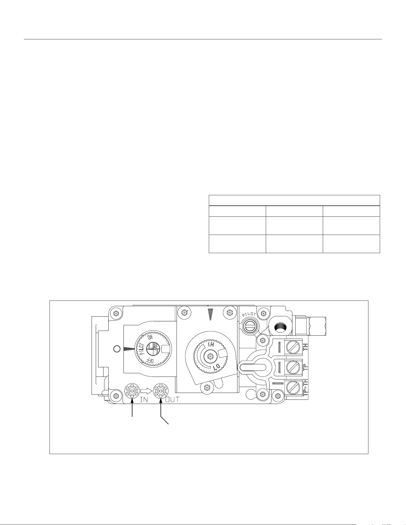
IMPORTANT: Pressure check taps for manifold (outgoing) and inlet
(incoming) pressure have been incorporated into the valve. The
pressure tap marked OUT measures outgoing pressure. The pressure
tap marked IN measures incoming pressure.
12.1.1 Inlet Pressure Test
NOTE: Make sure to apply the incoming pressure test with all other gas
appliances on, or at full capacity in the house for a proper pressure
reading. If the inlet pressure reading is too high or too low, contact the
gas company. Only a qualied gas service technician should adjust
incoming gas pressure. A low pressure can cause a delayed ignition.
1. Loosen the inlet (IN) pressure tap by turning screw
counterclockwise. See (A) in Figure 12.1.
2. Attach manometer using a ¼ in (6 mm) I.D. hose.
3. Light pilot.
4. Turn the gas control knob to ON. Burner should not light. Note
manometer reading.
5. Press the ON/OFF rocker switch to ON. Check pressure to ensure
it is near maximum inlet pressure.
6. Press the ON/OFF rocker switch to OFF.
7. Turn the gas control knob to OFF.
8. Disconnect hose and tighten the inlet (IN) pressure tap by
turning screw clockwise. Screw should be snug. Do not over
tighten.
9. Relight pilot and turn the gas control knob to ON. Reattach
manometer to the inlet pressure tap (A) to verify the tap is
completely sealed. Manometer should read no pressure.
12.1.2 Manifold Pressure Test
1. Light pilot.
2. Loosen manifold (OUT) pressure tap by turning screw
counterclockwise. See (B) in Figure 12.1.
3. Attach manometer to pressure tap using a ¼ in (6 mm) I.D. hose.
4. Turn gas control knob to ON.
5. Press the rocker switch to ON and note manometer reading.
6. Disconnect manometer hose and tighten the manifold (OUT)
pressure tap by turning screw clockwise. Screw should be snug.
Do not over tighten.
7. Attach the manometer to the manifold pressure tap (B) to verify
it is completely sealed. The manometer should read no pressure
when the ON/OFF rocker switch is pressed to ON.
Table 12.1, Pressure Requirements
Gas Pressure Natural Gas Propane
Inlet Pressure
Tap (A)
5” - 10.5” WC
(1.25 - 2.62 kPa)
11” - 13” WC
(2.74 - 3.24 kPa)
Manifold Pressure
Tap (B)
1.6” - 3.5” WC
(0.41 - 0.87 kPa)
6.4” - 10” WC
(1.59 - 2.48 kPa)
12.0 ADJUSTMENT
(A) INLET PRESSURE TAP
(B) MANIFOLD PRESSURE TAP
Figure 12.1, Pressure Check Taps Locations (Millivolt Gas Valve)
#CSK-29-MV R.8 October 2019 Hussong Mfg. Co., Inc. • Kozy Heat Fireplaces ADJUSTMENT 35
12.2 Burner Flame Adjustments
WARNING: To avoid property damage or personal injury, allow the
replace ample time to cool before making any adjustments.
Burner ame appearance and characteristics are aected by
altitude, fuel quality, venting conguration, and other factors. After
installation, this appliance may need additional adjustments to
achieve optimum ame appearance and visual aesthetics.
12.2.1 Burner Venturi
WARNING: VENTURI ADJUSTMENT MUST BE DONE BY A QUALIFIED
SERVICE TECHNICIAN.
NOTE: Burner venturi air shutter settings have been factory set. Refer
to Figure 12.3.
When this appliance is rst lit, the burner ames will appear blue.
During the rst 15 minutes of operation, ame appearance will
gradually turn to the desired yellow appearance. If the ames remain
blue, or become dark orange with evidence of sooting (black tips),
adjustment of the air shutter opening may be necessary.
Regardless of venturi orientation, closing the air shutter will achieve a
desired yellow ame, but may produce soot on the glass. Opening the
air shutter will cause a short, blue ame that may lift o the burner.
Table 12.2, Factory Set Venturi Openings
Fuel
Natural Gas 3/16” (4.8 mm) OPEN
Propane 5/8” (16 mm) OPEN
12.2.1.1 Venturi Adjustment
NOTE: If soot is present on the glass, check log positioning before
adjusting the venturi. Logs must not block burner ports.
1. Remove the safety barrier and glass frame assembly.
2. Remove the log set and burner assembly from rebox.
3. Loosen screw on venturi and adjust as necessary. Re-tighten
screw.
4. Reinstall all components previously removed.
IMPORTANT: Slight adjustments to the venturi opening will create
dramatic results. Adjust at slight increments until desired look is
achieved. Always burn the replace for at least 15 minutes, and
allow the appliance ample time to cool before making any further
adjustments.
Table 12.3, Venturi Adjustment Guidelines
Flame Characteristic Cause Solution
Dark, orange ame
with black tips
Venturi closed too far Open venturi slightly
Short, blue ames Venturi open too far Close setting slightly
Lifting (ghosting)
ames
Gas pressure too high
Venturi closed too far
Check manometer
settings
Open venturi setting
slightly
Lazy, yellow ames - no adjustment necessary
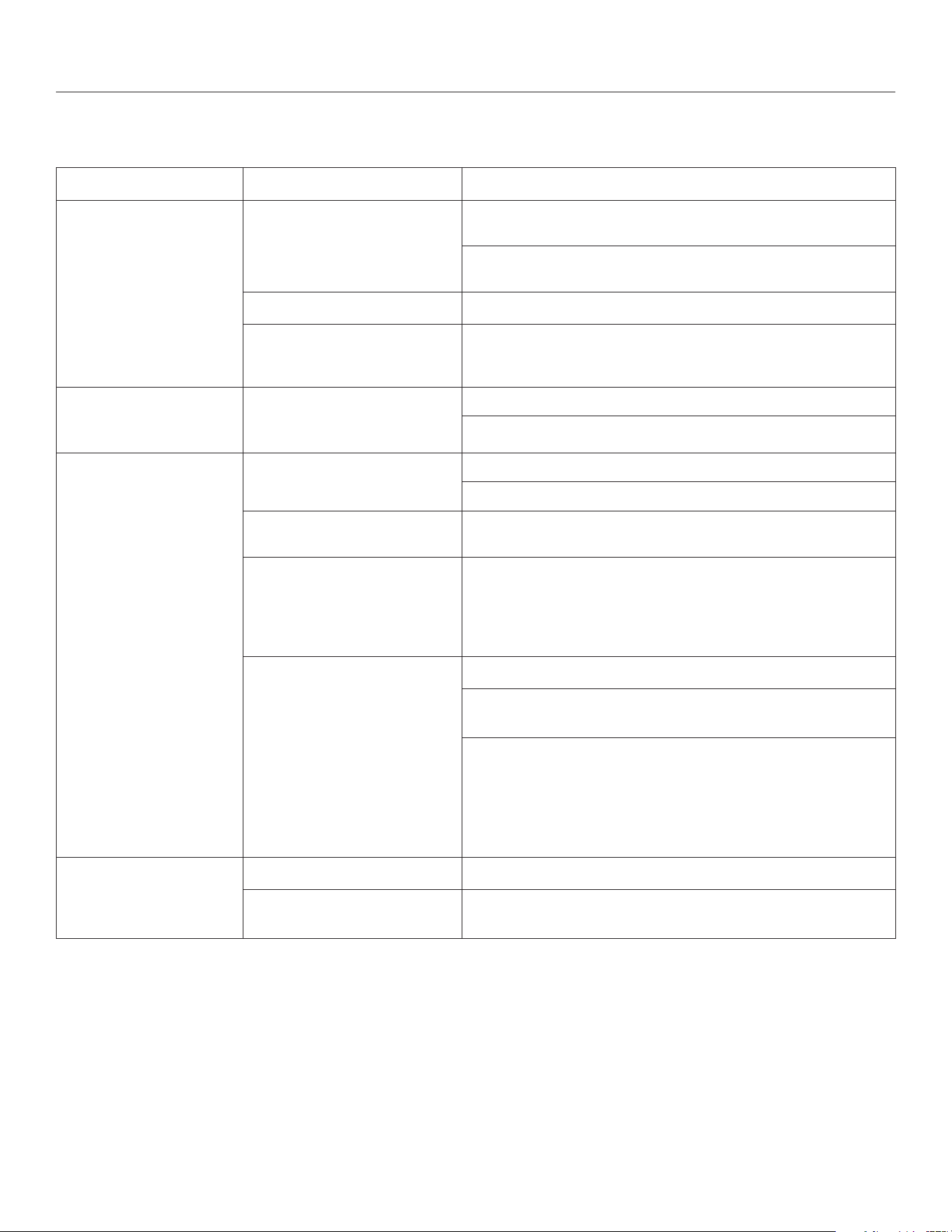
Ideal Flame Appearance
Figure 12.2, Burner Venturi Location
Figure 12.3, Flame Characteristics
BURNER VENTURI
Venturi(s) settings closed too far. Open venturi(s) slightly.
Dark, orange ames with black tips
Venturi(s) open too far. Close venturi settings(s) slightly.
Short, blue ames
Venturi settings(s) closed too far. Open venturi(s) slightly
OR gas pressure too high - check manometer settings
Lifting (ghosting) ames
36 TROUBLESHOOTING Hussong Mfg. Co., Inc. • Kozy Heat Fireplaces #CSK-29-MV R.8 October 2019
13.0 TROUBLESHOOTING
ATTENTION: Troubleshooting must be performed by a qualied
technician.
Issue Cause Solution
No spark from electrode to
pilot when piezo button is
triggered
Piezo igniter wiring disconnection
Verify piezo igniter is properly grounded. Tighten mounting fastener, if
required.
Check and repair, if necessary, the wire connections between the piezo
igniter and igniter electrode.
Check wiring disconnection
Check wiring at back of electrode igniter for proper connection.
Incorrect electrode position
Verify there is a 1/8 in (3 mm) gap between the electrode and pilot.
Readjust if necessary. Direct metal contact may cause an arc below the
electrode and along the electrode wire.
Spark igniter will not light
after repeated triggering of
piezo button
No gas
Check for multiple shut-o valves in the supply line.
Check propane tank for gas supply. Rell if necessary.
Pilot will not stay lit after
carefully following lighting
instructions
Pilot ame does not impinge on
thermocouple
Clean pilot hood
Adjust pilot ame at gas valve for proper ame impingement.
Loose thermocouple connection Ensure thermocouple connection at gas valve is full inserted and tight -
hand tight plus 1/4 turn.
Thermocouple reading below 15
millivolts
Disconnect the thermocouple from valve. Place one millivolt meter lead
wire on the end of the thermocouple, and the other millivolt meter lead
wire on the thermocouple’s copper wire. Start the pilot while holding
the gas valve control knob in.
If the millivolt reading is less than 15 millivolts, replace thermocouple.
Thermopile not generating
sucient millivolts
Adjust, if necessary, the pilot ame to envelope thermopile.
Check thermopile connections are properly wired to the gas control
valve. Tighten if necessary.
Measure millivolt production with a millivolt meter. Turn remote/
thermostat/wall switch, or ON/OFF rocker switch to OFF. Turn the gas
valve control to the PILOT position (pilot should remain lit).
Take millivolt reading at TH-TP and TP terminals on gas valve. Reading
should be 350 millivolts, minimum. If reading is less than 350 millivolts,
replace thermopile.
Frequent pilot outages
Pilot shield not installed
Install pilot shield.
Pilot safety dropout
Pilot ame is too high or too low. Clean pilot hood and adjust pilot ame
for maximum ame impingement on thermopile.
#CSK-29-MV R.8 October 2019 Hussong Mfg. Co., Inc. • Kozy Heat Fireplaces TROUBLESHOOTING 37
Issue Cause Solution
Burner will not light Lighting instructions not followed Turn gas control knob to ON position.
Turn the ON/OFF rocker switch to ON position.
Put wall switch, remote control, or thermostat in heat demand
position.
Plugged main burner orice Remove blockage as necessary.
Switching device is defective Check remote, thermostat, or wall switch wires for proper connection.
Place jumper wires across terminals at switch. If the burner lights,
replace the defective switch, thermostat, or batteries in remote
control as necessary.
If switching device checks out as described above, place jumper wires
across switches on the gas valve. If the burner lights, the switching
wires are faulty or connections are bad. Replace as necessary.
Burner will not stay lit Thermopile wires loose at valve
terminals
Tighten if necessary.
Thermopile wires ground out due
to pinched wires
Free pinched wires if necessary.
Improper refractory panel
placement (if installed)
Refractory panels must be tight against rebox walls. It may be
necessary to secure panels with high-temperature sealant, especially
around the intake duct.
Pilot and burner extinguish
while in operation
No propane in tank Check propane tank. Rell if necessary.
Incorrect glass frame assembly
installation
Refer toSection 9.1 Glass Assembly on page 27
Improper pitch on horizontal
venting
¼ in (6 mm) per 12 in (30 cm) is required on horizontal venting
Defective thermopile or
thermocouple
Check thermopile and thermocouple for proper millivolts
Inner vent pipe leaking exhaust
gases back into rebox
Check for leaks and repair if necessary.
Vent cap blockage Remove debris if necessary.
Glass sooting Improper log placement Refer to section 9.2 #CK29-500 Log Set Installation on page 28.
Improper venturi setting Venturi may need to be opened slightly to allow more air into the
gas mix. Refer to Section 12.2.1 Burner Venturi on page 35.
Incorrect vent cap installation Adjust if necessary.
Vent cap blockage Remove debris if necessary.
Flame burns blue and lifts o
burner
Improper venturi setting Venturi may need to be opened slightly to allow more air into the
gas mix. Refer to Section 12.2.1 Burner Venturi on page 35.
Incorrect vent cap installation Adjust if necessary.
Blockage or leakage of the vent
system
Check the vent pipe for leaks, and the vent cap for debris. Repair vent
pipe or remove debris from vent cap if necessary.

38 MAINTENANCE Hussong Mfg. Co., Inc. • Kozy Heat Fireplaces #CSK-29-MV R.8 October 2019
14.0 MAINTENANCE
ATTENTION: Installation and repair should only be done by a qualied
service person. The appliance should be inspected before use and at
least annually by a professional service person. More frequent cleaning
might be required due to excessive lint from carpeting, bedding
material, et cetera. It is imperative that control compartments, burners,
and circulating air passageways of the appliance be kept clean. Use a
vacuum to clean all components.
WARNING: The appliance area must be kept clear and free from
combustible materials, gasoline and other ammable vapors and
liquids.
14.1 Firebox
Performed by: Qualied Service Person
Frequency: Annually
Action:
• Vacuum and clean any debris in the rebox that is not supposed
to be there.
• Inspect and operate the bottom latch assembly. Verify the
assembly is free from obstruction to operate. The handles must
have spring tension but be able to move forward freely.
14.2 Fan
CAUTION: Label all wires prior to disconnection when servicing
controls. Wiring errors can cause improper and dangerous operation.
Verify proper operation after servicing.
Performed by: Qualied Service Person
Frequency: Every 6 months
Action:
• Disconnect the fan from electrical current and vacuum.
• The bearings are sealed and require no oiling.
14.3 Vent System
NOTE: If the vent-air intake system is disassembled for any reason,
reinstall per instructions provided with installation. Refer to Section
6.0 on page 15.
Performed by: Qualied Service Person
Frequency: Annually
Action:
• Examination of the vent system is required.
• The ow of combustion and ventilation air must not be
obstructed.
14.4 Glass Assembly
CAUTION: Do not operate appliance with the glass assembly removed,
cracked, or broken. Use protective gloves to handle any broken or
damaged glass assembly components.
WARNING: Do not use substitute materials.
WARNING: Avoid striking or slamming glass assembly. Avoid abrasive
cleaner. DO NOT clean glass while it is hot.
IMPORTANT: Any safety screen, guard, or barrier removed for servicing
the appliance must be replaced prior to operating the appliance.
Performed by: Homeowner
Frequency: Annually
Action:
• Prepare a work area large enough to accommodate the glass
assembly on a at, stable surface.
• Remove safety screen and glass frame assembly.
• Clean glass window with a suitable replace glass cleaner using
a soft cloth. Abrasive cleaners must not be used. Be careful not to
scratch the glass when cleaning.
• Reinstall glass assembly and safety screen. Do not operate
replace without safety screen.
Performed by: Qualied Service Person
Frequency: Annually
Action:
• Clean glass window with a suitable replace glass cleaner using
a soft cloth. Abrasive cleaners must not be used. Be careful not to
scratch the glass when cleaning.
• Inspect the glass for cracks, scratches, and nicks.
• Verify the glass assembly is properly intact and not damaged.
• Replace the glass and the assembly #701-009T as necessary.
• Only Hussong Mfg. Co., Inc. will supply the replacement of glass
assembly as a complete unit.
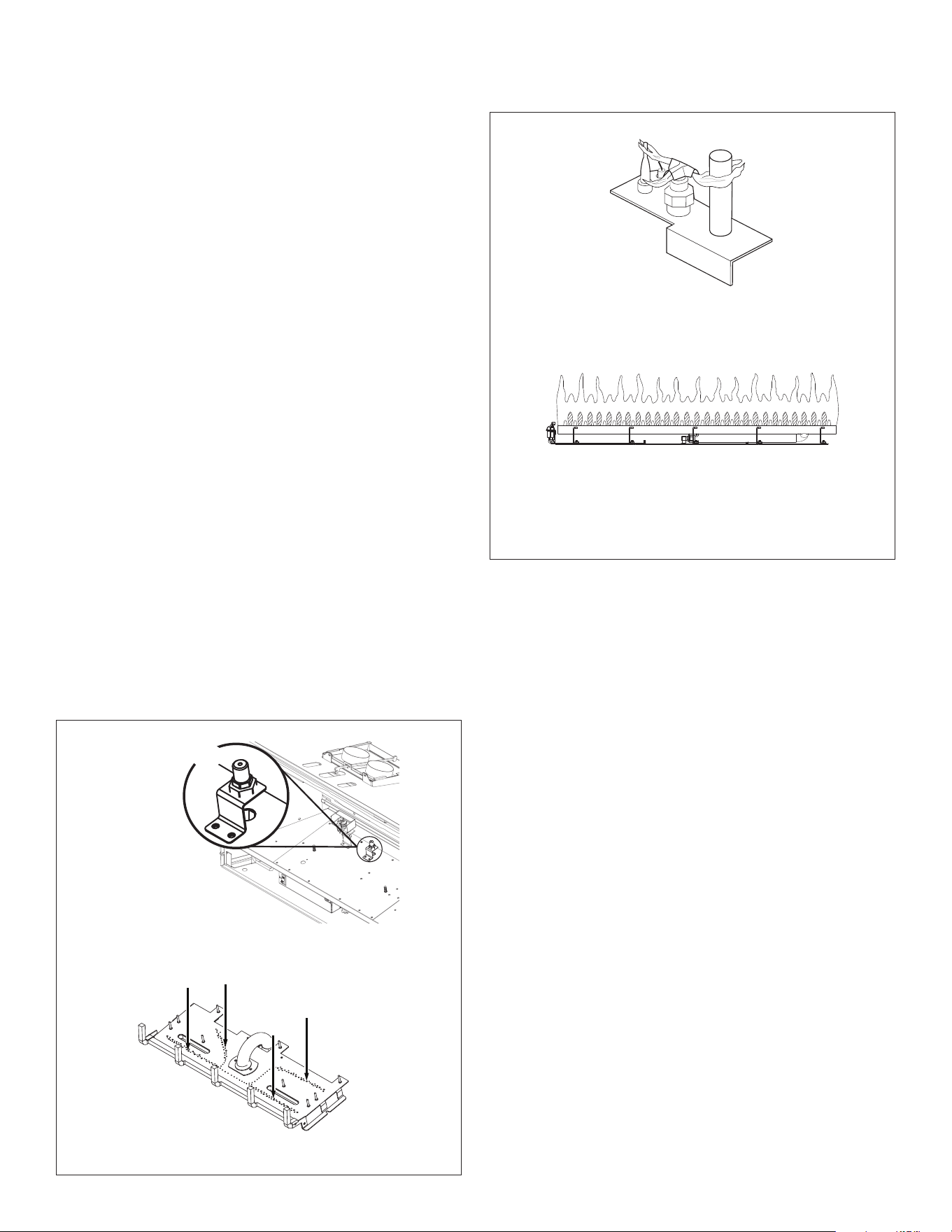
#CSK-29-MV R.8 October 2019 Hussong Mfg. Co., Inc. • Kozy Heat Fireplaces MAINTENANCE 39
14.5 Burner and Pilot System
The burner assembly may be removed for easier access to the control
compartment. See Section 9.3 Control Board Removal and Installation
on page 29 for instructions.
Verify gas supply is turned on and lled. Consult with plumber or gas
supplier as necessary.
Performed by: Qualied Service Person
Frequency: Annually
Action:
• Vacuum all components of the burner system.
• Check all accessible gas-carrying tubes, connections, pipes and
other components for leaks.
• Inspect the operation of the ame safety system Pilot or Flame
rectication device. Visually check pilot light when in operation.
• Ensure pilot ame impinges on thermocouple. Clean pilot
hold and adjust pilot ame at gas valve for proper ame
impingement. Verify thermocouple connections and millivolt
production.
• Inspect and ensure the lighting of the main burner occurs within
(4) seconds of the main gas valve opening. Check for faulty or
incorrect wiring and correct or replace as necessary. Inspect
primary air openings (burner ports) for blockage, especially near
the pilot.
• Visually check burner ame pattern when in operation. Flames
should be steady, not lifting or oating.
• Test and measure the ame failure response time of the ame
safety system. It must de-energize the safety shuto in no more
than (30) seconds.
Figure 14.1, Burner System
Lazy, yellow ames - no adjustment necessary
Ideal Flame Appearance
Figure 14.2, Pilot and Burner Correct Flame Appearance
BURNER ORIFICE
BURNER PORTS
HONEYWELL MILLIVOLT
PILOT FLAME
40 REPLACEMENT PARTS LIST Hussong Mfg. Co., Inc. • Kozy Heat Fireplaces #CSK-29-MV R.8 October 2019
15.0 REPLACEMENT PARTS LIST
#CSK-29-MV
Hussong Manufacturing Co., Inc.
P.O. Box 577
204 Industrial Park Drive
Lakeeld, MN 56150-0577
USA
Replacement parts are available through your local dealer. Contact your local dealer for availability and pricing.
WARNING: This product can expose you to chemicals including Lead, which is [are] known to the State of California to cause cancer, birth
defects, or other reproductive harm. For more information, visit www.P65Warnings.ca.gov.
The following warning is for replacement parts for this appliance.
CONTROL BOARD AND PARTS
Control Board - NG CK29MV-770 Thermocouple 700-058
Control Board - Propane CK29MV-771 Pilot Orice - NG 700-294
SIT Gas Valve - NG 700-086N Pilot Orice - Propane 700-295
SIT Gas Valve - NG (7 day time-out) 700-086N-7 Pilot Hood 700-098
SIT Gas Valve - Propane 700-087A 18” Flexible Gas Line - Black 700-213B
SIT Gas Valve - Propane (7 day time-out) 700-087A-7 Flexible Gas Line - Valve to Burner Connection 700-226F
On/O Rocker Switch 700-023 NG Burner Orice #42 700-242
Pilot/Generator/Thermocouple - NG 700-063 Propane Burner Orice #53 700-253
Pilot/Generator/Thermocouple - Propane 700-063-1 Conversion Kit - NG OCK-S42A
Piezo Igniter with nut (no wire) 700-090 Conversion Kit - Propane OCK-S53A
Flexible Pilot Tubing (valve to pilot) 700-091 Burner Assembly CK29L-135
Millivolt Generator 700-092
GLASS AND GLASS PARTS
Glass with Gasket 14-5/8” x 27-3/4” 701-009T
Glass Gasket 900-006
SAFETY BARRIERS
Prairie Screen Front CK29-PSF
Rectangular Screen Front CK29-RSF
Arched Mission Screen Front CK29A-MSF
Arched Prairie Screen Front CK29A-PSF
Arched Screen Front CK29A-SF
Arched Full Prairie Door Screen Front CK29A-FPDSF2
SHROUDS
Blank Shroud (4 pc.) CK29-004
4 sided blank shroud (4 pack) CK29-008
25” x 38” shroud (1 piece) CK29-2538
27-1/2” x 42” shroud (1 piece) CK29-27542
30” x 44” shroud (1 piece) CK29-3044
28” x 38” arched shroud (1 piece) CK29A-2838
Custom shroud CK29-CUS
Custom arched shroud CK29-ACUS
LOG SET
8 Piece Log Set CK29-500
Ember Panel CK29-900E
#CK29-1 Log CK29 1
#CK29-2 Log CK29 2
#CK29-3 Log CK29 3
#CK29-4 Log CK29 4
#CK29-5 Log CK29 5
#CK29-6 Log CK29 6
#CK29-7 Log CK29 7
#CK29-8 Log CK29 8
Rock Wool Embers 900-REMB
FAN KIT
Fan Kit CK29-028-MV
ADDITIONAL COMPONENTS
Manual Gas Shut-o Valve 700-203
Upper Louver CK29-202
Lower Louver CK29-201

#CSK-29-MV R.8 October 2019 Hussong Mfg. Co., Inc. • Kozy Heat Fireplaces LIMITED LIFETIME WARRANTY 41
LIMITED LIFETIME WARRANTY
Warranty Coverage
Hussong Manufacturing Company, Inc. (Hussong Mfg.) warrants this
Kozy Heat gas appliance from the date of purchase to the original
purchaser, that it is free of defects in materials and workmanship at
the time of manufacture. Registering your replace warranty does not
require any documents to be sent in to Hussong Mfg. Please retain
your proof of purchase reecting the date of purchase along with the
serial number and model of your replace for any future warranty
claims.
If a defect is noted within the warranty period, the customer should
contact their authorized dealer for service within 30 days.
30 Days: Parts & Labor*
• Paint
• Light bulbs
• Gasket material
• Glass media and media dam
Year 1: Parts & Labor*
• All parts and material except the items listed in the 30 day
warranty and any exclusions or limitations that may apply.
*Hussong Mfg. will issue labor reimbursement to an authorized dealer
only. Hussong Mfg. will not be liable for charges occurred as a result of
any service performed by a non-authorized service provider, without
pre-authorization.
Years 2 through Lifetime: Parts Only
• Firebox
• Heat Exchanger
• Logs
• Burner tube or pan
• Outer shell
• Heat shield(s)
• Front Viewing Glass (thermal shock only)
• Refractory Firebox liner (excluding enamel and glass panels)
EXCLUSIONS AND LIMITATIONS
1. This appliance must be installed by a licensed, authorized service technician or contractor. It must be installed, operated and maintained
at all times in accordance with the instructions in the owner’s manual or the warranty is void.
2. This warranty is nontransferable and is made to the original purchaser only.
3. This warranty excludes standard wear and tear of the appliance which is considered normal usage over time.
4. Discoloration and some minor expansion, contraction or movement of certain parts, resulting in noise, is normal and not a defect.
5. Warranty is automatically voided if the appliance’s serial number and/or testing label is removed or if the appliance is altered or
tampered with in any way.
6. Warranty is void if the appliance is subject to submersion in water or prolonged periods of dampness or condensation. Any damage
to any part of the appliance due to water or weather damage which is the result of, but not limited to, improper chimney/venting
installation will also render this warranty void.
7. This warranty does not cover installation and operational related problems such as environmental conditions, nearby trees, buildings,
hilltops, mountains, inadequate venting or ventilation, excessive osets, negative air pressures caused by any mechanical systems.
8. Chimney components and other Non-Hussong Mfg. accessories used in conjunction with the installation of this appliance are not
covered under this warranty.
9. Damage to plated surfaces or accessories, if applicable, caused by scratches, ngerprints, melted items or other external sources left on
the surfaces from the use of cleaners is not covered under this warranty.
10. It is expressly agreed and understood that this warranty is Hussong Mfg.’s sole obligation and purchaser’s exclusive remedy for defective
replace equipment. Hussong Mfg. is free of liability for any damages caused by this appliance, as well as inconvenience expenses
and materials. Incidental or consequential damages are not covered by this warranty. In some states, the exclusion of incidental or
consequential damage may not apply. Hussong Mfg. shall not be held to implied warranties and this warranty shall replace all previous
warranties.
11. This limited lifetime warranty is the only warranty supplied by Hussong Mfg. Any warranties extended to the purchaser by the dealer/
distributor, whether expressed or implied, are hereby disclaimed and the purchaser’s recourse is expressly limited to the warranties set
forth herein.
12. Any part repaired or replaced during the limited warranty period will be warranted under the terms of the limited warranty for a period
not to exceed the remaining term of the original limited warranty.
13. Any replacement part repaired after the warranty period will include a 90 day parts coverage
14. Hussong Mfg. may require the defective part to be returned using a pre-authorized RGA number or a photo of the defective component.
Failure to provide either can result in a denied claim.
15. This warranty does not cover the appliances ability to heat a desired space, as there are many factors that can impact the heating
performance in each home. Consideration should be implied to the appliance’s location, room size, home design, environmental
conditions, insulation, and tightness of the home.
16. Hussong Mfg. reserves the right to make changes at any time, without notice, in design, material, specications, and prices. Hussong
Mfg. reserves the right to discontinue models and products.
July 2018