Loading ...
Loading ...
Loading ...

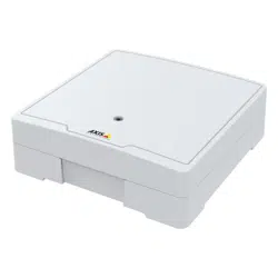
AXISA1610NetworkDoorController
Specifications
FunctionPinNotes
Specications
DCground(GND)
1
0VDC
NO
2
Normallyopen.
Forconnectingrelaydevices.Connectafail-secure
lockbetweenNOandDCground.
Thetworelaypinsaregalvanicallyseparatedfromthe
restofthecircuitryifthejumpersarenotused.
COM
3
Common
NC
4
Normallyclosed.
Forconnectingrelaydevices.Connectafail-safelock
betweenNCandDCground.
Thetworelaypinsaregalvanicallyseparatedfromthe
restofthecircuitryifthejumpersarenotused.
Maxcurrent=2Aperrelay
Maxvoltage=30VDC
Relaypowerjumper
Whentherelaypowerjumperistted,itconnects12VDCor24VDCtotherelayCOMpin.
ItcanbeusedtoconnectalockbetweentheGNDandNO,orGNDandNCpins.
Powersource
Maxpowerat12VDC
1
Maxpowerat24VDC
1
DCIN
1600mA800mA
PoE800mA400mA
1.ThepowerissharedbetweenthetworelaysandAUXI/O12VDC.
NO NO
NO
TICE TICE
TICE
Ifthelockisnon-polarized,werecommendyoutoaddanexternalybackdiode.
Auxiliaryconnector
Usetheauxiliaryconnectorwithexternaldevicesincombinationwith,forexample,motiondetection,eventtriggering,andalarm
notications.Inadditiontothe0VDCreferencepointandpower(DCoutput),theauxiliaryconnectorprovidestheinterfaceto:
Digitalinput-Forconnectingdevicesthatcantogglebetweenanopenandclosedcircuit,forexamplePIRsensors,door/window
contacts,andglassbreakdetectors.
Supervisedinput-Enablespossibilitytodetecttamperingonadigitalinput.
Digitaloutput-ForconnectingexternaldevicessuchasrelaysandLEDs.ConnecteddevicescanbeactivatedbytheVAPIX®
ApplicationProgrammingInterfaceorfromtheproduct’swebpage.
6–pinterminalblock
24
Loading ...
Loading ...
Loading ...
