Operating instructions
For the operator
GB, IE
Operating instructions
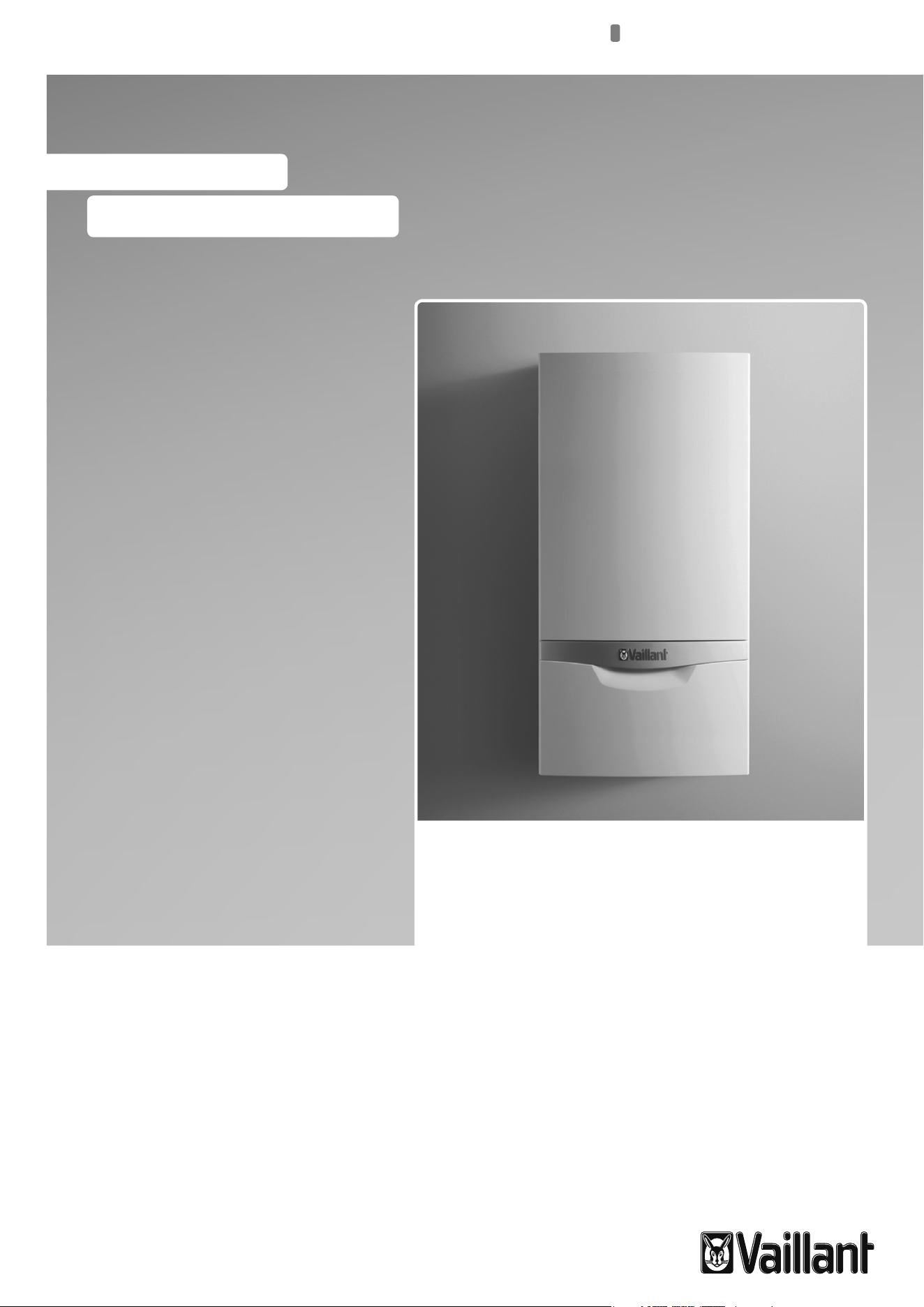
ecoTEC
Gas-fired wall-hung high-efficiency boiler

Table of contents
2 Operating instructions ecoTEC plus 0020134822_01
Table of contents
1 Notes on the documentation .....................................3
1.1 Storing documents ..........................................................3
1.2 Applicability of the instructions ...................................3
1.3 Identification plate ........................................................... 3
1.4 CE label ...............................................................................3
1.5 Benchmark .........................................................................3
2 Safety ................................................................................. 4
2.1 Safety and warning information ..................................4
2.2 Intended use ......................................................................4
2.3 General safety information ............................................5
3 Description of devices and functions ......................7
3.1 Design .................................................................................7
3.2 Function ..............................................................................7
3.3 Hot water production with domestic hot water
cylinder ...............................................................................7
4 Operation ..........................................................................8
4.1 Overview of the controls ................................................8
4.2 Digital Information and Analysis System (DIA) ........8
4.3 Operating concept ...........................................................9
4.4 Basic display .................................................................... 10
4.5 Operating levels ............................................................. 10
4.6 Preparing for start-up .....................................................11
4.7 Setting the heating flow temperature .......................13
4.8 Hot water generation .....................................................14
4.9 Setting a room thermostat or weather
compensator ....................................................................14
4.10 Switching off the functions of the boiler ..................14
4.11 Protecting the heating installation against frost ....16
5 Troubleshooting .............................................................17
5.1 Reading fault messages ................................................17
5.2 Reading fault codes ....................................................... 18
5.3 Detecting and rectifying faults ................................... 18
5.4 Rectifying low water pressure .....................................19
5.5 Resolving ignition faults ................................................19
5.6 Service message ........................................................... 20
5.7 Resolving faults in the air/flue gas duct ................ 20
6 Auxiliary functions ..................................................... 20
6.1 Operation in the menu................................................. 20
6.2 Displaying the Live monitor
(current status of the boiler).......................................22
6.3 Setting the display contrast ........................................22
6.4 Setting the language .....................................................22
6.5 Displaying contact data for the competent
person ...............................................................................23
6.6 Displaying the serial number and article number .23
6.7 Reset burner off time
(resetting burner anti-cycling time) ..........................23
7 Service .............................................................................23
7.1 Servicing the boiler .......................................................23
7.2 Caring for your boiler ...................................................23
8 Decommissioning .........................................................24
8.1 Disposing of the boiler .................................................24
8.2 Disposing of the packaging .........................................24
9 Manufacturer's guarantee and
Vaillant customer services .......................................24
9.1 Factory guarantee ..........................................................24
9.2 Vaillant Service ...............................................................24
10 Glossary ..........................................................................25
Index ...........................................................................................26
Brief operating instructions ....................................................27
Notes on the documentation
Operating instructions ecoTEC plus 0020134822_01 3
1
1 Notes on the documentation
The following instructions are intended to guide you
throughout the entire documentation. Other documents
apply in addition to these operating instructions.
We accept no liability for any damage caused by failure to
observe these instructions.
Other applicable documents
When operating the ecoTEC plus, you must observe all
operating instructions that are included with other compo-
nents of your system.
These operating instructions are included with the individ-
ual components of the system.
Further instructions for all accessories and controllers used
also apply.
The benchmark checklist for starting up gas-fired boilers
(contained in the installation instructions) must be com-
pleted by the Health and Safety Executive-approved heating
specialist company and/or the competent person present
during the commissioning and must be passed on to the
system operator. After reading through these instructions, if
you have any questions regarding the operation of the
boiler, please contact your recognised Health and Safety
Executive-approved heating specialist company or Vaillant's
technical department.
In these instructions, the heating specialist company and
competent person approved by the Health and Safety Exec-
utive will be abbreviated as the heating specialist company
and competent person.
1.1 Storing documents
> Store these operating instructions and all other applica-
ble documents in such a way that they are available
whenever required.
1.2 Applicability of the instructions
These operating instructions apply exclusively to boilers
with the following article numbers:
Unit Type designation Article number
ecoTEC plus VU GB 806/5-5 0010010767
ecoTEC plus VU GB 1006/5-5 0010010780
ecoTEC plus VU GB 1206/5-5 0010010791
1.1 Type overview
To find out the article number of your boiler, refer to the
identification plate.
1.3 Identification plate
The identification plate of your Vaillant ecoTEC plus boiler
is attached at the factory to the underside of your boiler.
The seventh to sixteenth digits of the serial number on the
identification plate represent the article number.
1.4 CE label
The CE label shows that the units comply with
the basic requirements of the applicable direc-
tives as stated on the identification plate.
1.5 Benchmark
i
Vaillant Ltd. supports the Benchmark Initiative.
A benchmark checklist for commissioning floor-
standing gas-fired boilers is attached to these
installation instructions. It is very important that
this document be filled out properly when
installing, commissioning and handing-over to
the system operator.
4 Operating instructions ecoTEC plus 0020134822_01
a
Safety
a
2
2 Safety
2.1 Safety and warning information
> When operating your boiler, observe the general safety
information and the warning notes that appear before
each action.
2.1.1 Classification of warnings
The warning notes are classified in accordance with the
severity of the possible danger using the following warning
signs and signal words:
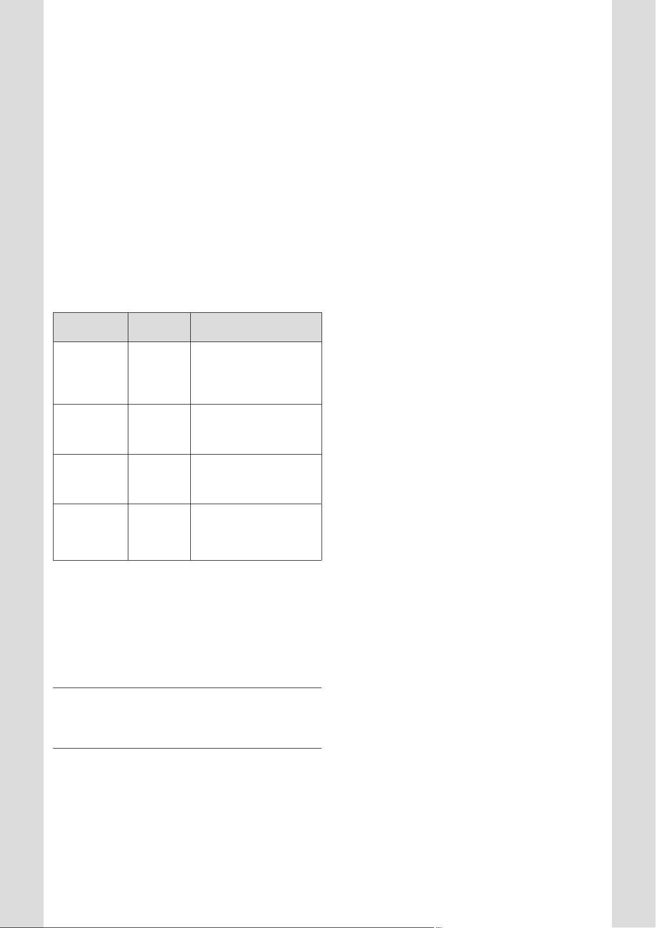
Warning signs Signal
word
Explanation
a
Danger!
Immediate risk of death or
risk of severe personal
injury
e
Danger!
Risk of death from electric
shock
a
Warning!
Risk of minor personal
injury
b
Caution!
Risk of material or environ-
mental damage
2.1 Meaning of warning signs and signal words
2.1.2 Structure of warnings
Warning signs are identified by an upper and lower separat-
ing line and are laid out according to the following basic
principle:
a
Signal word!
Type and source of danger.
Explanation of the type and source of danger
> Measures for averting the danger
2.2 Intended use
The Vaillant ecoTEC plus boilers are state-of-the-art appli-
ances which have been constructed in accordance with rec-
ognised safety regulations. Nevertheless, there is still a risk
of injury or death to the operator or others or of damage to
the boiler and other property in the event of improper use
or use for which it is not intended.
This boiler is not designed to be used by persons (including
children) with limited mental and sensory capabilities or by
persons who do not have enough experience and/or knowl-
edge, unless they are supervised by a person who is respon-
sible for their safety or they have been instructed by him/
her about how to use the boiler.
Children must be watched to ensure that they do not play
with the boiler.
The boiler is intended for use as a heater in closed hot
water central heating installations and hot water genera-
tion.
The use of the ecoTEC plus in vehicles, such as mobile
homes and caravans, is not classed as intended use. Units
that are not classed as vehicles are those that are installed
in a fixed and permanent location and that do not have any
wheels (fixed installation).
Any other use, or use beyond that specified, shall be con-
sidered improper use. Any direct commercial or industrial
use is also deemed to be improper.
The manufacturer or supplier is not liable for any damage
resulting from such use. In this case, the user alone bears
the risk. Intended use includes:
– observance of accompanying operating, installation and
maintenance instructions for the Vaillant product as well
as for other parts and components of the system
– installation and assembly in accordance with the unit
and system approval
– compliance with all inspection and servicing conditions
listed in the instructions.
Caution
Any improper use is forbidden.
Operating instructions ecoTEC plus 0020134822_01 5
a
Safety
a
2
2.3 General safety information
> Observe the following safety instructions at all times.
Installation and settings
The boiler must only be installed by a suitably qualified
competent person. The existing regulations, rules and
guidelines must be observed when doing so.
This person is also responsible for inspection, maintenance
and repairs to the boiler, as well as alterations to the gas
volume setting.
What to do if you smell gas in buildings
Installation errors, damage, manipulation, unauthorised
installation sites or similar can cause gas to escape and
result in a risk of poisoning and explosion. If there is a smell
of gas in the building, proceed as follows:
> Avoid rooms that smell of gas.
> Open all accessible doors and windows fully and ensure
adequate ventilation.
> Avoid the use of naked flames (e.g. lighters, matches).
> Do not smoke.
> Do not use any electrical switches, mains plugs, door-
bells, telephones or other intercommunication systems in
the building.
> Close the gas meter isolator device or the main isolator
device.
> If possible, close the gas isolator cock on the boiler.
> Warn other occupants in the building by calling out or
banging on doors or walls.
> Leave the building.
> If you can actually hear gas leaking, leave the building
immediately and ensure that others do not enter the
building.
> Alert the fire brigade and police when you are outside
the building.
> Use a telephone outside the building to inform the emer-
gency service department of the gas supply company.
National phone number for gas emergencies:
0800 111 999
2.1 Close the gas isolator cock
What to do in an emergency if you smell flue gas
Installation errors, damage, tampering with the unit, unau-
thorised installation sites or similar can cause flue gas to
escape and result in a risk of poisoning. If there is a smell of
flue gas in the building, proceed as follows:
> Open all accessible doors and windows fully and ensure
adequate ventilation.
> Switch the boiler off.
> Inform a heating specialist company.
Explosives and highly flammable substances
The risk of explosion arises from the flammable mixture of
gas and air. Take note of the following:
> Do not use or store explosive or highly flammable sub-
stances (such as petrol or paint) in the same room as the
boiler.
Preventing scalding
There is a risk of scalding at the hot water draw-off points if
the hot water temperatures are greater than 60 °C. Young
children and elderly persons are particularly at risk, even at
lower temperatures.
> Select the temperature so that nobody is at risk.
Preventing material damage due to unauthorised
changes to the appliance.
Take note of the following:
> Never interfere or tamper with the boiler or other parts
of the heating installation.
> Never try to carry out maintenance work or repairs on
the boiler yourself.
> Do not damage or remove any seals on components.
Only suitably qualified competent persons or our customer
service may alter sealed components.
Material damage caused by corrosion
To prevent corrosion on the boiler and also on the flue gas
installation, note the following:
> Do not use any sprays, solvents, chlorinated cleaning
agents, paint, adhesives or similar substances in the
vicinity of the boiler.
Under unfavourable circumstances, these substances may
cause corrosion.
Preventing frost damage
If there is a power cut, or if the room temperature is set too
low in individual rooms, it cannot be ruled out that sections
of the heating installation may be damaged by frost.
> If you are going to be away during a cold period, ensure
that the heating installation remains in operation and
that the rooms are sufficiently heated.
> Always observe the information on frost protection pro-
vided in (¬section 4.11)
Even if rooms, or the whole dwelling, are not in use for cer-
tain periods, the heating must remain in operation.

6 Operating instructions ecoTEC plus 0020134822_01
a
Safety
a
2
Caution.
Frost protection and monitoring devices are only active
while the boiler is connected up to the power supply. The
boiler must be connected to the power supply. The boiler
must be switched on. You can see from symbols and/or text
in the display that the boiler is switched on.
Caution.
> Under no circumstances should you add frost protection
agents (or other additives, e.g. jointing compounds, cor-
rosion protection agents, etc.) to the heating water with-
out first consulting your qualified competent person.
Otherwise, it could result in damage to seals and dia-
phragms as well as noise during heating mode. Vaillant
assumes no liability for this or any consequential dam-
age.
Another way to protect the heating installation and the
boiler from frost is to drain them. In doing so, you must
ensure that the heating installation and boiler are com-
pletely drained.
> Contact your approved heating specialist company for
advice on this.
Maintaining operation with an emergency power
generator in the event of a power cut
Your recognised heating specialist company connected your
boiler to the power mains during installation.
If the electricity supply is cut, it is possible that parts of the
heating installation may become damaged by frost.
If you want to maintain the operation of the boiler during a
power cut using an emergency power generator, take note
of the following:
> Make sure that the technical values of this generator
(frequency, voltage, earthing) match those of the power
mains.
> Contact your approved heating specialist company for
advice on this.
Changes to the boiler's environment
You must not make any changes to the boiler's environ-
ment:
> Never shut down the safety devices.
> Do not tamper with any of the safety devices.
> Do not make any changes:
– to the boiler
– to the gas, air, water and electricity supply lines,
– to the entire flue gas installation,
– to the entire condensate drain system,
– to the expansion relief valve or the drain line or
– to constructional conditions that could affect the
operational reliability of the boiler.
Cabinet-type cladding
> If you require cabinet-type cladding for your boiler, con-
sult an approved heating specialist company. Do not,
under any circumstances, enclose your boiler yourself.
Enclosing the boiler in cabinet-type cladding requires com-
pliance with the special design instructions.
What to do if there are leaks in the hot water pipes
Take note of the following:
> In the event of leaks, immediately close the cold water
stop valve in the domestic hot water pipework between
the boiler and the draw-off points.
> Have the leak repaired by an approved heating specialist
company of your choice.
With Vaillant ecoTEC plus boilers, the cold water stop valve
is not included in the scope of delivery of your boiler.
> Ask your competent person where he fitted the cold
water stop valve.
Preventing damage caused by low system pressure
in the heating installation
To prevent the heating installation being used when the
amount of water is too low and to therefore prevent any
subsequent damage that may be caused by this, note the
following:
> Check the filling pressure of the heating installation at
regular intervals.
> Always observe the information on filling pressure pro-
vided in ¬section 4.6.3.
Requirements for the installation site
It is not necessary to keep a clearance between the boiler
and combustible materials or components because, at the
nominal heat output of your boiler, the temperature on the
surface of the housing is always lower than the maximum
permissible temperature of 85 °C.
Description of devices and functions
Operating instructions ecoTEC plus 0020134822_01 7
3
3 Description of devices and functions
3.1 Design
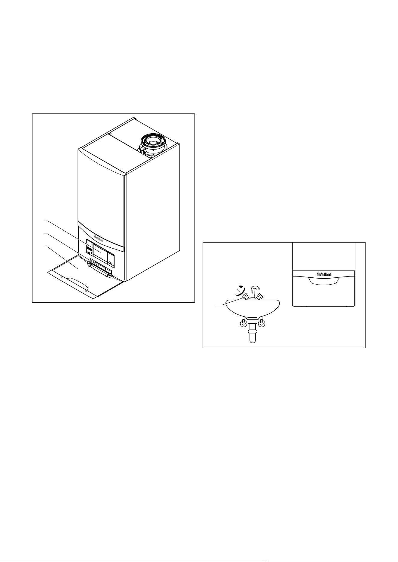
1
3
2
3.1 Front view of the ecoTEC plus
Key
1 Controls
2 Plate with serial number on the rear
2 Front flap
The controls for your boiler are arranged behind the front
flap.
To access the controls, open the front flap as follows:
> Take hold of the recessed handle in the front flap.
> Fold down the front flap.
3.2 Function
Your Vaillant ecoTEC plus is a gas-fired wall-hung high-effi-
ciency boiler, which generates heat for heating and/or hot
water production.
VU boilers can be operated together with a domestic hot
water cylinder, which stores a larger volume of hot water.
3.2.1 Heating mode
In Heating mode, the boiler heats the hot water and sends
it through the radiators or underfloor heating of your home
(heating circuit). The hot water pumped into the heating cir-
cuit exits the boiler at a specific heating flow temperature,
emits its heat into the rooms and flows back into the boiler
once cooled to return temperature. The heating water is
then heated again.
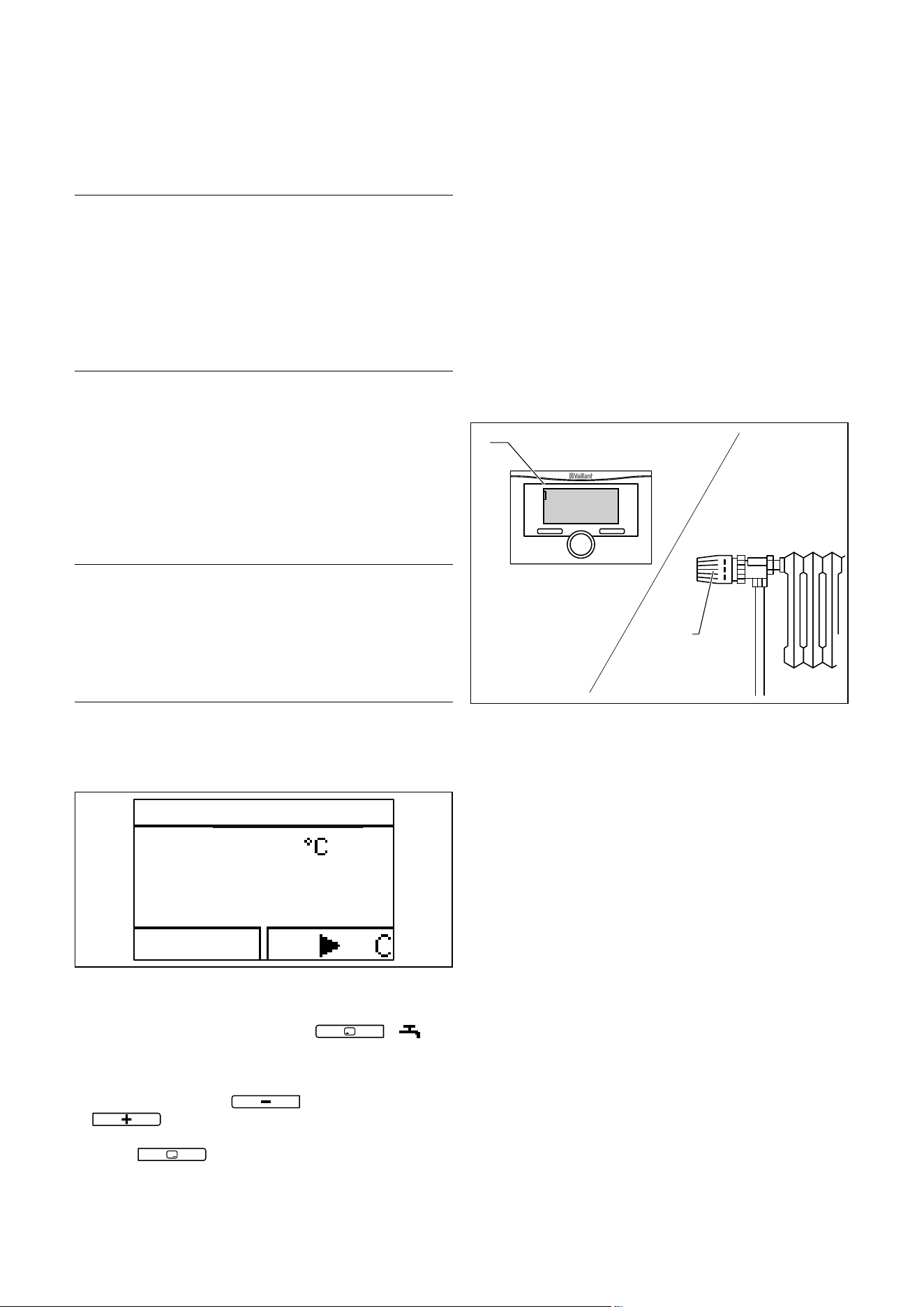
3.3 Hot water production with domestic hot
water cylinder
1
3.2 Drawing hot water
When you open a hot water valve (1) (sink, shower, bath,
etc.), the hot water is taken from the domestic hot water
cylinder.
Cold water than flows into the domestic hot water cylinder
in its place. If the hot water temperature in the domestic
hot water cylinder falls below the value set, then the boiler
operates automatically and reheats the domestic hot water
cylinder. As soon as the water in the domestic hot water
cylinder has reached the set temperature, the boiler
switches off.
Operation
8 Operating instructions ecoTEC plus 0020134822_01
4
4 Operation
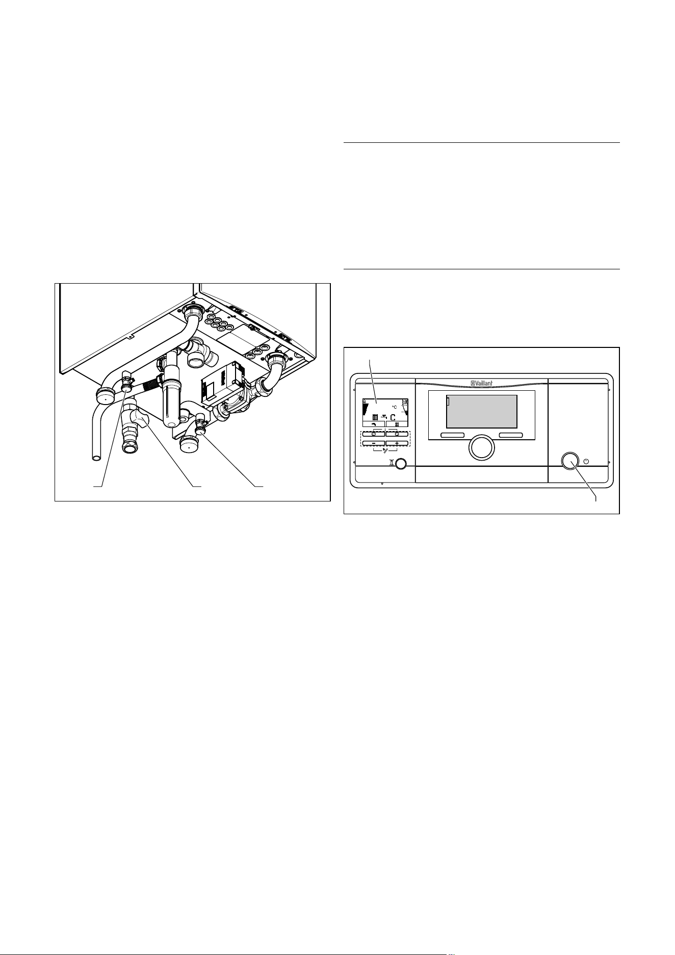
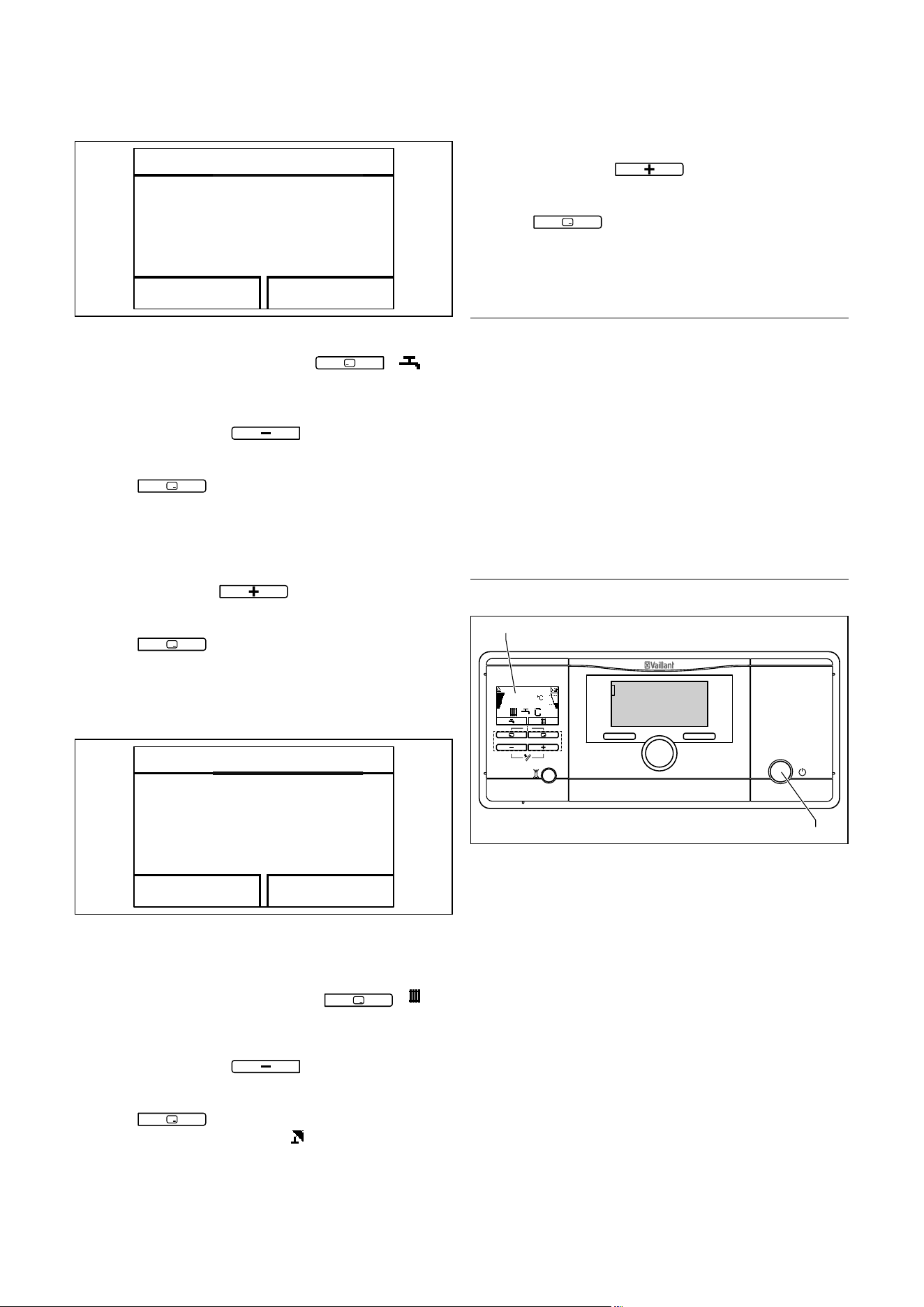
4.1 Overview of the controls
1234
5
4.1 ecoTEC plus controls
1 On/off button for switching the boiler on or off
2 Controller (accessory)
The Digital Information and Analysis System
consists of:
3 Fault clearance key to clear certain faults
4 Operating buttons
5 Display
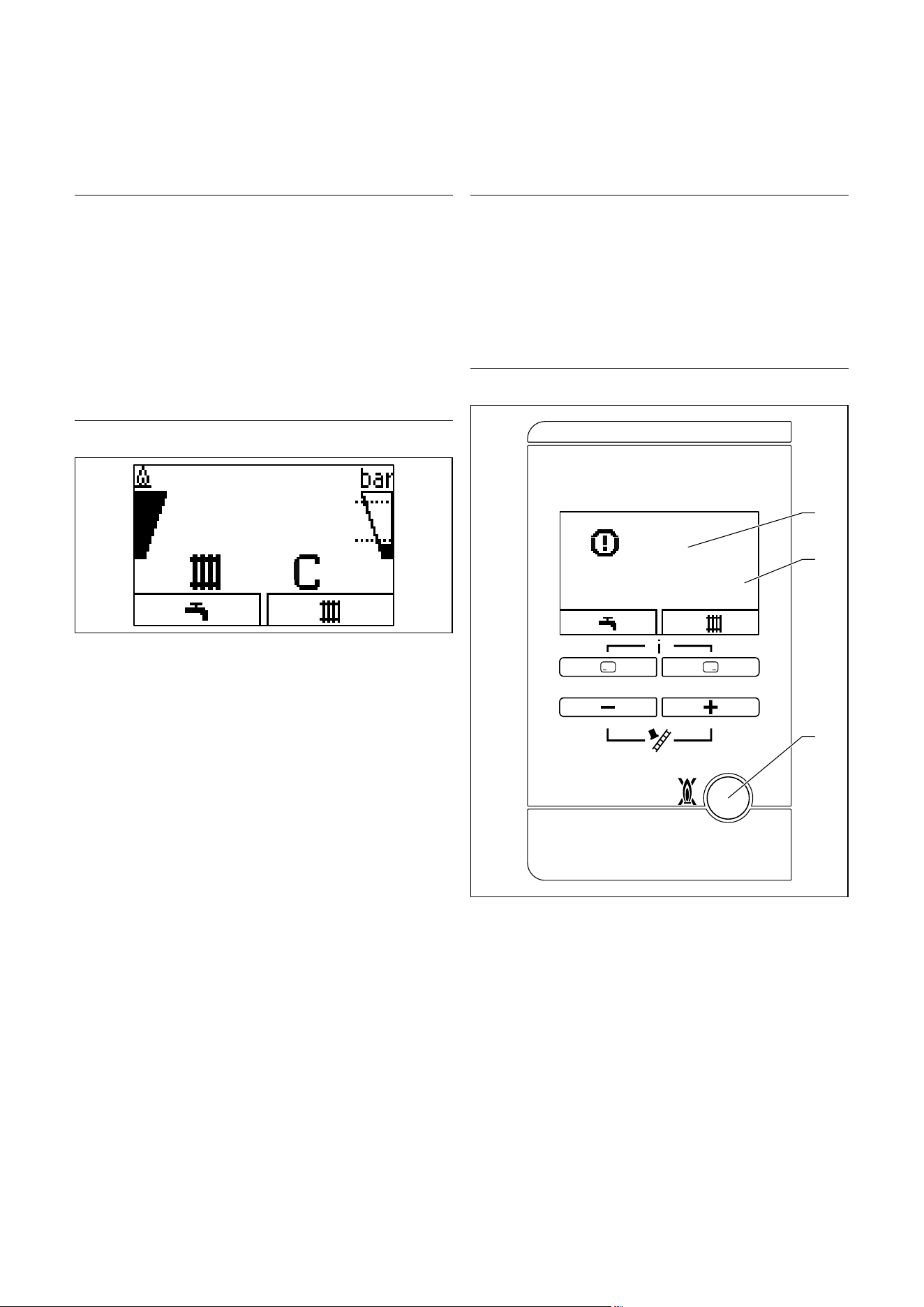
4.2 Digital Information and Analysis System
(DIA)
The ecoTEC plus boiler is equipped with a Digital Informa-
tion and Analysis System (DIA system). This consists of a
display showing symbols and plain text, along with 5 opera-
tion buttons. This system provides information on the oper-
ating status of your boiler and helps you deal with prob-
lems.
The display lights up,
– if you switch the boiler on or
– if you press a button for the DIA system when it is
switched on. At first, pressing this button does not trig-
ger any other function.
The light automatically switches off after one minute if you
do not press any button.
50
F. 0 1
1
2
3
4
8
7
6
5
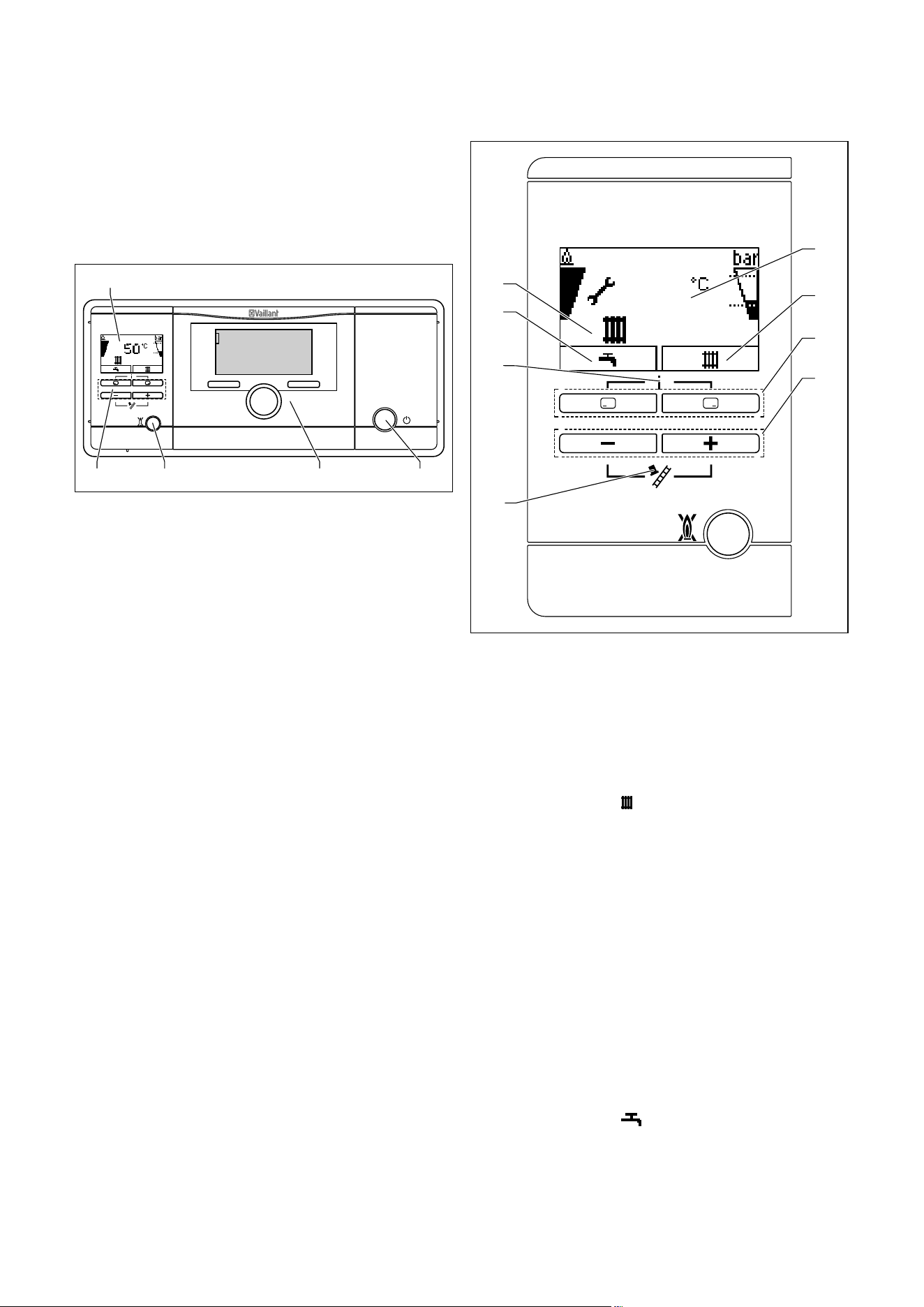
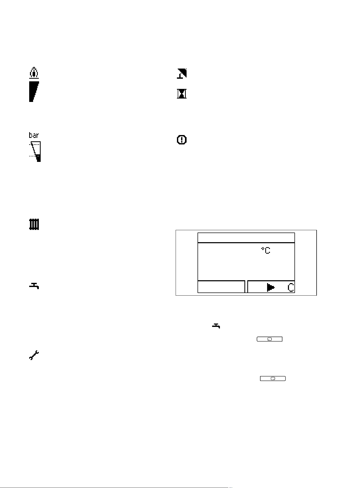
4.2 DIA system with possible symbol displays
1 Display indicating the current heating flow tempera-
ture, the filling pressure of the heating installation,
the operating mode, a fault code or other additional
information in plain text
2 Display of the current configuration of the right-hand
selector button (after switching on the boiler and in
the basic display:
= heating temperature)
3 Left and right-hand selector buttons
Left-hand selector button: "Process water" for
selecting and calling up the water temperature.
Right-hand selector button: "Heating mode" for
s
electing and calling up information, such as the
heating temperature and water pressure in the
heating circuit, for example
4 Minus and plus button
5 Maximum output mode (for chimney sweeps only)
6 Access to the menu for additional information
7 Display of the current configuration of the left-hand
selector button (after switching on the boiler and in
the basic display:
= hot water temperature set-
ting)
8 Display of the symbols for the active operating status
Operation
Operating instructions ecoTEC plus 0020134822_01 9
4
Displayed symbols
Flame:
Permanently on: Correct burner operation; burner
on
Display of the current burner modulation rate (bar
graph display)
Display of the current filling pressure of the heating
installation (bar graph display).
The filling pressure must be in the mid range
between the two dotted lines.
Permanently on: The filling pressure is within the
permitted range.
Flashing: The filling pressure is outside of
the permitted range.
Heating mode active
Permanently on: Heating mode heat requirement
Flashing: Burner on in Heating mode
Hot water generation active
Permanently on: Time period activated for hot
water generation
Flashing: Domestic hot water cylinder is
being heated, burner on
Maintenance required. In the "Live monitor", you
can read further information about the reason for
the service (¬section 6.2).
Additional symbols:
Summer mode active
Heating mode is switched off
Burner anti-cycling time active
This function is used to prevent frequent on/off
operations, and therefore contributes to prolonging
the life of your boiler. The symbol also appears if
the boiler is in a waiting period.
F. X X
Fault in the boiler. Appears instead of the basic dis-
play (¬section 4.4).
A plain text display explains the displayed fault
code.
Example; F.10 Flow NTC short circuit.
4.3 Operating concept
You can operate the boiler using the selector buttons and
the plus/minus buttons.
Both selector buttons have a soft key function. This means
that their function may change.
45
DHW temperature
Back
4.3 Display after pressing the left-hand selector button
If, forexample, you press the left-hand selector button in
the basic display (¬section 4.4), the current function
s
witches from "
" (hot water temperature) to "Back".
With the left-hand selector button
:
– you can navigate directly to set the hot water tempera-
ture
– you can cancel the change to a set value or the activa-
tion of an operating mode
– you can go one selection level higher in the menu
With the right-hand selector button
:
– you can navigate directly to set the heating flow temper-
ature and to the precise value of the water pressure of
the heating installation
– you can confirm a set value or the activation of an oper-
ating mode
– you can go one selection level lower in the menu
Operation
10 Operating instructions ecoTEC plus 0020134822_01
4
With both selector buttons + at the
same time:
– you can navigate to the menu (¬section 6)
With the minus button
or the plus button
:
– you can go back and forth between the individual points
of the entry list in the menu
– you can increase or decrease a selected set value
Adjustable values are always displayed as flashing. You
must always confirm a change to a value. Only then is the
new setting saved.
You always have the option to cancel the change to a set-
ting or the reading of a value by pressing the left-hand
selector button.
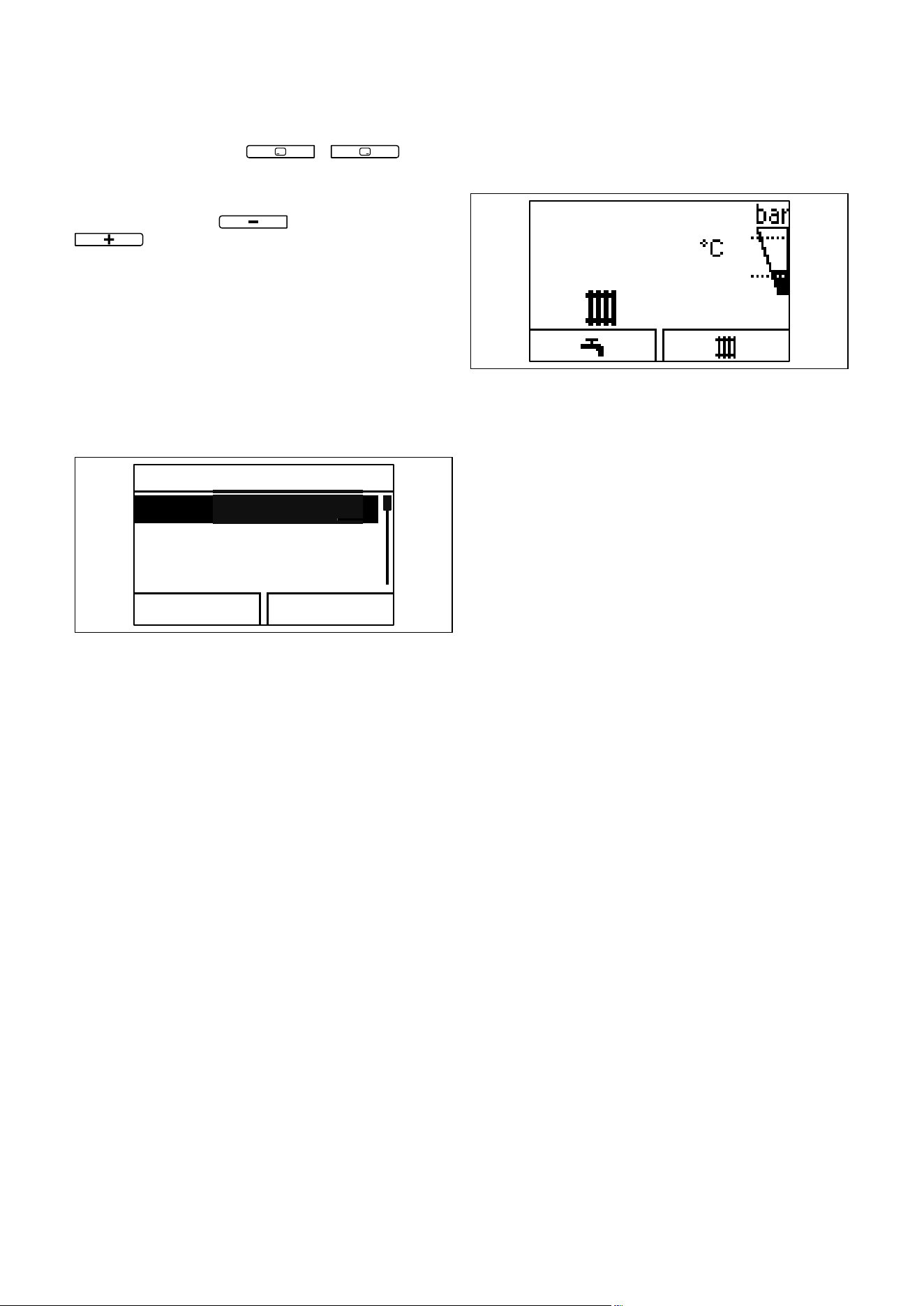
Menu
Water pressure
Live Monitor
Information
Back Select
4.4 Selecting a list entry in the menu
A highlighted object is indicated in the display by the
selected value flashing.
i
If you do not press any buttons for more than 15
minutes, the display returns to the basic display.
Changes that are not confirmed will not be
applied.
4.4 Basic display
50
4.5 Basic display
In the normal operating status, you can see the basic dis-
play in the display. The basic display shows the current sta-
tus of the boiler. If you press a selector button, the relevant
activated function is displayed in the display. If the display
becomes dark, the light is switched on by the first press of
the button. In this case, to trigger the button function, you
must press the button again.
You can switch back to the basic display by:
– pressing the left-hand selector button and exiting the
selection levels
– not pressing any button for longer than 15 minutes.
Changes that are not confirmed will not be applied.
If there is a fault message, the basic display switches to a
plain text display of the fault message.
From the basic display, you can directly change and read
the most important settings and information by pressing
the selector buttons.
The functions that are available depend on whether a con-
troller is connected to the boiler.
4.5 Operating levels
The boiler has two operating levels.
Operating level
The operating level for the operator offers you the most
frequently used setting options that do not require any spe-
cial prior knowledge and displays the most important infor-
mation. You can access additional information using a
menu.
Competent person level
The operating level for the competent person must only be
operated with expertise and is therefore protected by a
code. This level is used by the competent person to adjust
the parameters for the boiler to the heating installation.
Operation
Operating instructions ecoTEC plus 0020134822_01 11
4
4.6 Preparing for start-up
4.6.1 Opening the isolator devices
i
The isolator devices are included in the scope of
delivery of your boiler. The isolator devices are
fitted by your competent person on site.
> He must explain to you the position and handling of
these components.
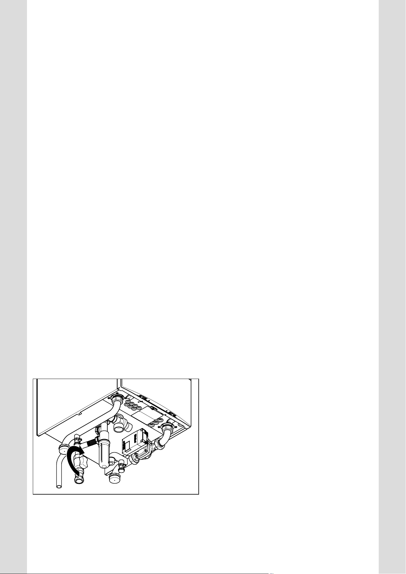
123
4.6 Opening the isolator devices
(shown using the example of service valves)
> Open the gas isolator cock (2), by pushing the gas isola-
tor cock in and turning it anti-clockwise.
> Check that the heating flow (3) and heating return (1)
service valves are open. This is the case if the T-handle
on the service valve matches the direction of the pipe.
4.6.2 Switching on the boiler
b
Caution.
Material damage caused by frost.
Frost protection and monitoring devices are
only active while the boiler is connected up
to the power supply.
> Do not isolate the boiler from the power
supply.
> Leave your boiler switched on at the on/
off switch.
To ensure that the frost protection and monitoring devices
remain active, switch your boiler on and off using the con-
troller (see the corresponding operating instructions).
¬ Section8 describes how to fully shut down your boiler.
50
1
2
4.7 Switching on the boiler
> Press the on/off switch (1) to switch on the boiler.
If the boiler is switched on, the current heating flow tem-
perature and other information will appear in the display
(2) (Fig.4.5 ).
To set your boiler to suit your needs, read section 4.7 to
section 4.8 which describe the setting options for hot
water generation and Heating mode.
Operation
12 Operating instructions ecoTEC plus 0020134822_01
4
4.6.3 Checking the filling pressure of the heating
installation
b
Caution.
Low filling pressure may cause damage
to the unit.
Operating the heating installation with low
filling pressure can cause damage to the
boiler and the heating installation. The
boiler switches off automatically when the
filling pressure falls too low.
> Fill up the heating installation as soon as
the filling pressure falls below 0.08MPa
(0.8 bar).
To avoid operating the system with insufficient water and to
prevent possible damage associated with this, your boiler is
fitted with a pressure sensor. This signals the low pressure
level if the level falls below 0.08MPa (0.8bar) by the water
pressure value in the display flashing.
> Fill up the heating installation as soon as the pressure
value in the display starts to flash. (¬ section 4.6.4).
i
If the filling pressure of the heating installation
falls below 0.05MPa (0.5 bar), then the boiler
switches off and the fault message F. 2 2 appears
in the display.
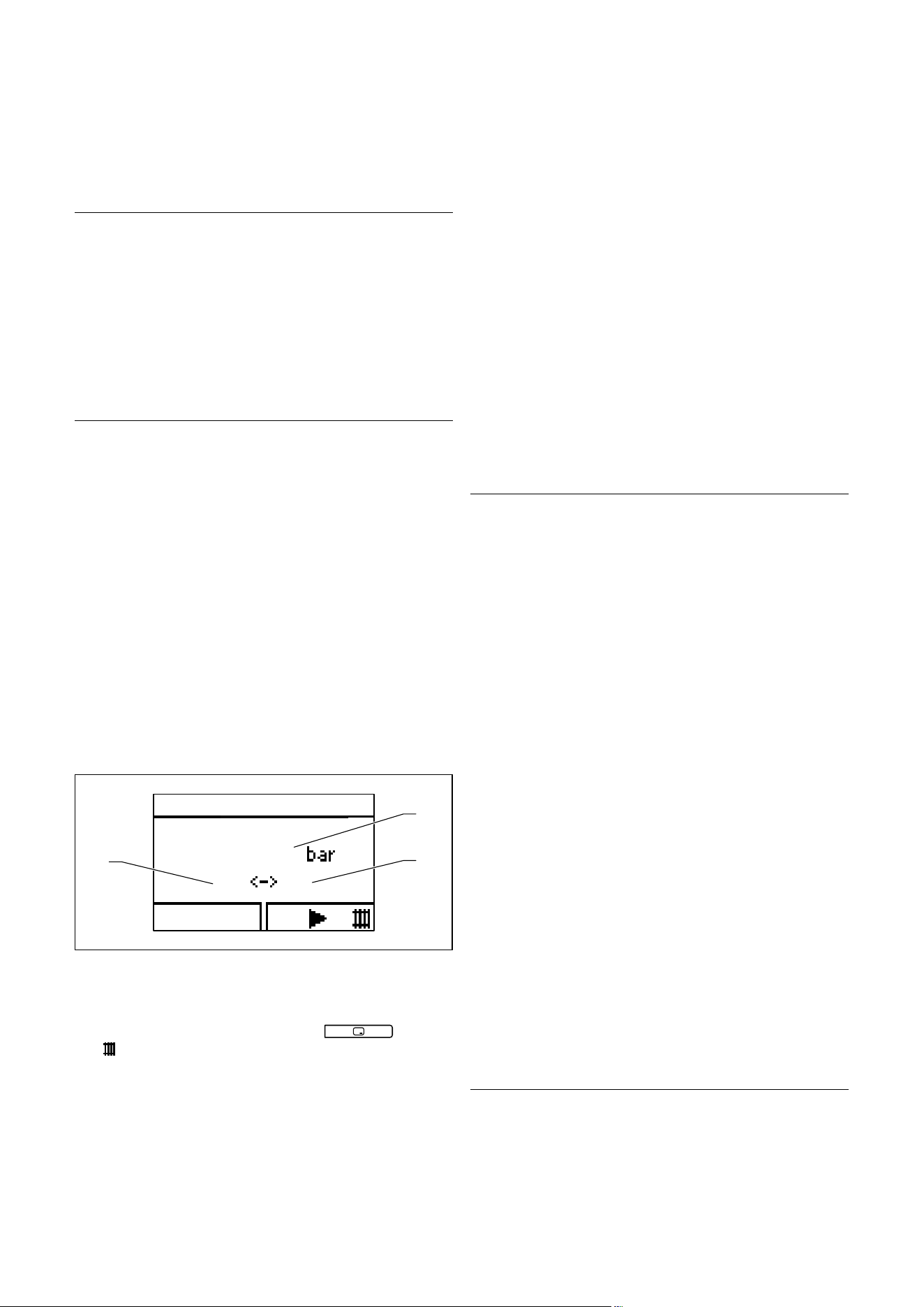
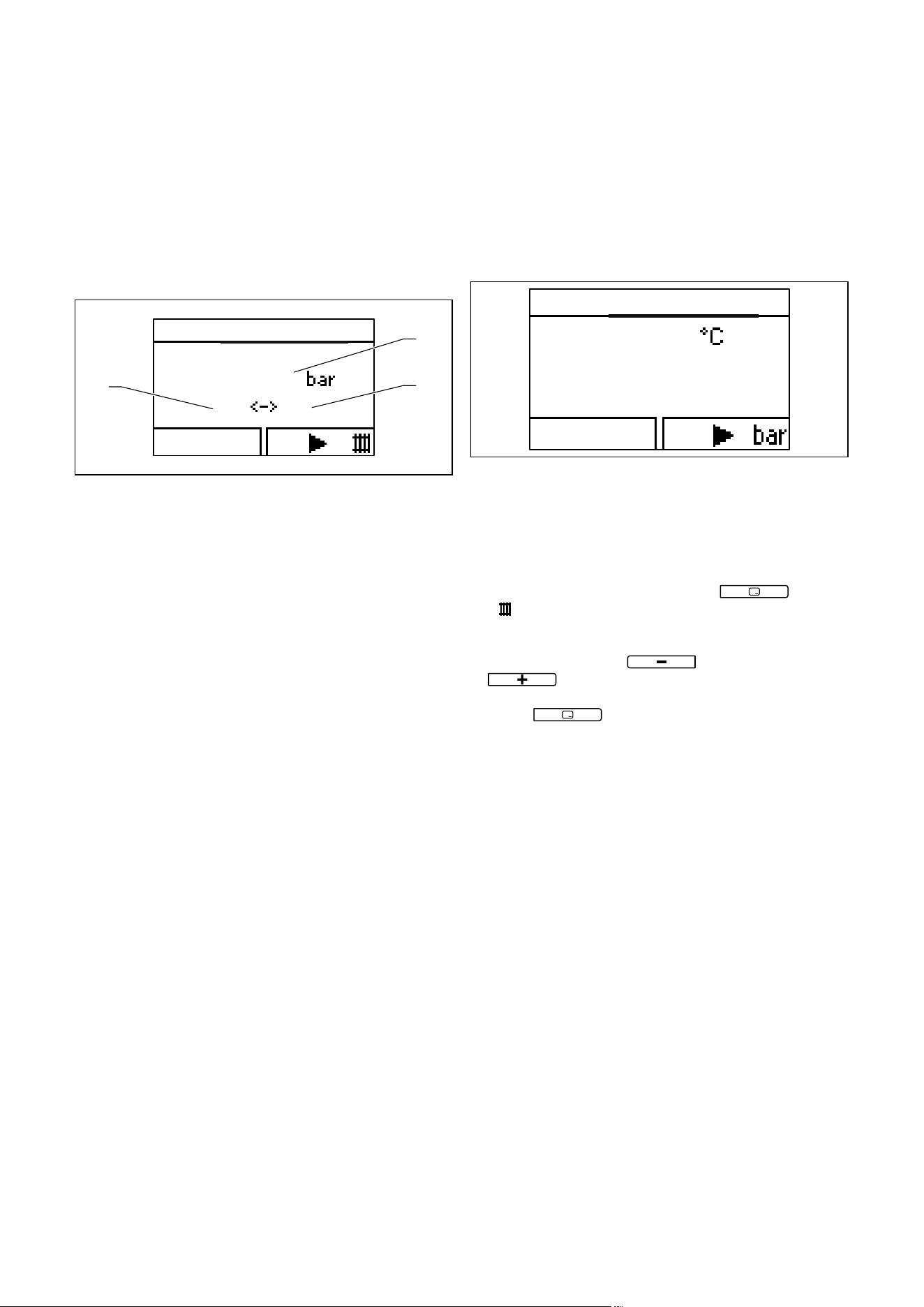
The ecoTEC plus boiler has a digital pressure display. You
can see the filling pressure in the right bar graph display or
display the exact value using the selector buttons to the
right of the display.
1,0
Water pressure
Back
0,8 6,0
1
2
3
4.8 Digital display of filling pressure
> Press the on/off switch (1) (¬Fig. 4.7), to switch on the
boiler
> Press the right-hand selector button
twice.
("
")
The value of the flow temperature appears in the display.
Press the right-hand selector button to access the water
pressure display.
The current filling pressure (1) and the minimum (3) or
maximum water pressure (2) that is to be set appear in the
display.
If the heating installation extends over several storeys, a
higher filling pressure may be required for the heating
installation.
> Ask your competent person for details.
The filling pressure must lie between 0.01MPa (1.0 bar) and
0.04MPa (4.0 bar) when the heating installation is cold in
order for the heating installation to operate properly. If the
filling pressure is below this range, then you must top up
the water before start-up.
> Check the filling pressure of the heating installation dur-
ing start-up.
4.6.4 Filling the heating installation
b
Caution.
Tap water that is extremely calciferous
or corrosive or contaminated by chemi-
cals can cause damage to the boiler.
Unsuitable tap water damages the seals
and diaphragms, blocks components in the
boiler and heating installation through
which the water flows and causes noise.
The heating installation must be hydrauli-
cally separated from the unit using a plate
heat exchanger. If the heating installation
and boiler are operated with a system sepa-
ration device, water treatment will not be
necessary up to a hardness of 4.48mol/m
3
(448 mg/l). Should there be good grounds
not to use a system separation device, the
heating water must be processed according
to strict guidelines. This must take place in
a treatment plant.
> Only fill the heating installation with suit-
able water. The calcium content of the
water should not exceed the following
hardness in relation to the stated system
volumes:
- 1000 l: up to 1.09 mol/m
3
(109 mg/l)
- 2000 l: up to 0.55 mol/m
3
(55 mg/l)
- 4000 l: up to 0.26 mol/m
3
(26 mg/l)
- 7200 l: up to < 0.14 mol/m
3
(14 mg/l)
To this end, both the water used for ini-
tial filling and the water for any top-ups
must be treated.
> In case of doubt, consult your competent
person.
Operation
Operating instructions ecoTEC plus 0020134822_01 13
4
The heating installation is filled via a filling cock provided
by the installer (if a system separation device is used
between the unit heating circuit and the building heating
circuit).
> Ask your competent person where the filling cock is
located.
> Ask your competent person to explain how to fill the
heating installation.
1,0
Water pressure
Back
0,8 6,0
1
2
3
4.9 Digital display of filling pressure
You can show the exact filling pressure in the display
(¬section 4.6.3).
Proceed as follows to fill the heating installation (building
heating circuit):
> Open all radiator valves (thermostatic radiator valves) of
the heating installation.
> Connect the filling cock for the heating installation, as
explained by your competent person, to a filling system.
> Open the filling cock slowly.
> Fill it with water until the required filling pressure is
reached in the display.
> Close the filling system valve.
> Purge all the radiators.
> Then check the filling pressure on the display.
> Fill with more water if required.
> Close the filling cock.
When filling the unit heating circuit, the filling pressure pro-
file can be tracked on the unit display
> Press the "Next" or "Back" selector button until you
have reached the desired level or the basic display.
If you do not press any buttons for more than 15 minutes,
the display returns to the basic display.
4.7 Setting the heating flow temperature
4.7.1 Setting the heating flow temperature
without a controller connected
60
Target flow temp.
Back
4.10 Setting the heating flow temperature
If no external controller is connected to the boiler, set the
heating flow temperature according to the respective out-
side temperature as follows:
> Press the on/off switch to switch on the boiler.
> Press the right-hand selector button
("
").
The value of the heating flow temperature appears in the
display.
> Use the minus button
or the plus button
to change the heating flow temperature.
> Confirm the change by pressing the right-hand selector
button
("OK").
The heating flow temperature is factory-set for tempera-
tures up to 75 °C.
If higher (or lower) values can be set on your boiler, this
means that your competent person has calibrated your unit
to adjust the maximum temperature to your heating instal-
lation.
4.7.2 Using a controller to set the heating flow
temperature
If your gas-fired wall-hung boiler has a room thermostat
control system or weather compensator, make the following
settings:
> Press the on/off switch to switch on the boiler.
> Set the maximum heating flow temperature
(¬section4.7.1).
The actual heating flow temperature is automatically
adjusted by the controller (for information about this, see
the controller operating instructions).
Operation
14 Operating instructions ecoTEC plus 0020134822_01
4
4.8 Hot water generation
a
Danger!
Risk of being scalded by hot water!
There is a danger of scalding at the hot
water draw-off points when the tempera-
tures are in excess of 60 °C. Young children
and elderly persons are particularly at risk,
even at lower temperatures.
> Select the temperature so that nobody is
at risk.
a
Danger!
Possible risk of death caused by
legionella formation!
In domestic hot water cylinders there is a
risk of legionella forming, which can cause
illness.
> If the unit is used for post-heating within
a solar-supported drinking water heating
installation, set the domestic hot water
outlet temperature to at least 60 °C.
b
Caution.
Material damage due to calcification.
If the water hardness is more than
3.57 mol/m
3
(=357 mg/l), there is a risk of
calcification.
> Set the maximum water temperature to
50 °C.
To generate hot water in conjunction with the VU unit type,
a VIH-type domestic hot water cylinder must be connected
to the boiler.
45
DHW temperature
Back
4.11 Setting the hot water temperature
> Press the on/off switch to switch on the boiler.
> Press the left-hand selector button
(" ").
The hot water temperature that is set is shown flashing on
the display.
> Use the minus button
or the plus button
to change the hot water temperature.
> Confirm the change by pressing the right-hand selector
button
("OK").
If your controller is connected to the boiler via a dual-cable
eBUS line, you can set the target hot water target tempera-
ture on the controller. Ask your competent person whether
or not your controller is connected via a dual-cable eBUS
line.
If your controller is connected via a dual-cable eBUS line:
> Set the hot water temperature on the boiler to the maxi-
mum possible temperature.
> Set the desired hot water temperature
4.9 Setting a room thermostat or weather
compensator
2
1
4.12 Setting the room thermostat/weather
compensator
> Set the room thermostat, weather compensator (1) and
thermostatic radiator valves (2) as specified in the oper-
ating manuals for these accessories.
4.10 Switching off the functions of the boiler
4.10.1 Switching off hot water generation
(VU boiler)
If a domestic hot water cylinder is connected, you can
switch off the cylinder charging without switching off Heat-
ing mode.
Operation
Operating instructions ecoTEC plus 0020134822_01 15
4
DHW temperature
Cylinder charging off
Cancel Ok
4.13 Switching off cylinder charging
> Press the left-hand selector button (" ").
The domestic hot water temperature that is set is shown
flashing on the display.
> Use the minus button
to set the hot water
temperature to "Cylinder charging off"
> Confirm the change by pressing the right-hand selector
button
("OK").
Cylinder charging is switched off. Only the frost protection
function for the cylinder remains active.
To switch the cylinder charging on again:
> Use the plus button
to set your required hot
water temperature.
> Confirm the change by pressing the right-hand selector
button
("OK").
4.10.2 Switching off Heating mode ( Summer mode)
Heating off
Target flow temp.
Cancel Ok
4.14 Switching off Heating mode (Summer mode)
You can switch off Heating mode in summer without switch-
ing off the hot water generation.
> Press the right-hand selector button
(" ").
The value of the heating flow temperature appears in the
display.
> Use the minus button
to set the heating flow
temperature to "Heating off".
> Confirm the change by pressing the right-hand selector
button
("OK").
Heating mode is switched off. The
symbol appears on the
display.
To switch Heating mode on again:
> Use the plus button
to set your required
heating flow temperature.
> Confirm the change by pressing the right-hand selector
button
("OK").
4.10.3 Temporarily shutting down the boiler
b
Caution.
Risk of damage caused by frost.
Frost protection and monitoring devices are
only active while the boiler is connected up
to the power supply and the on/off switch is
on.
> Do not isolate the boiler from the power
supply.
> Leave your boiler switched on at the on/
off switch.
> Only switch the boiler on and off in nor-
mal mode using the controller.
> Make sure that the boiler cannot become
damaged by frost.
50
1
2
4.15 Switching off the boiler
> Press the on/off switch (1) to switch off the boiler.
If the boiler is switched off, the display (2) turns off.
i
If the boiler is going to be decommissioned for
longer periods (e.g. holiday), you should also
close the gas isolator cock and the cold water
stop valve, but only if there is no risk of frost.
i
The isolator devices are included in the scope of
delivery of your boiler. These are fitted by your
competent person on site.
> Ask your competent person to explain to you the posi-
tion and handling of these isolator devices.

Operation
16 Operating instructions ecoTEC plus 0020134822_01
4
4.11 Protecting the heating installation against
frost
b
Caution.
Risk of damage caused by frost.
Frost protection and monitoring devices are
only active while the boiler is connected up
to the power supply and the on/off switch is
on.
> Do not isolate the boiler from the power
supply.
> Leave your boiler switched on at the on/
off switch.
b
Caution.
Tap water that is extremely calciferous
or corrosive or contaminated by chemi-
cals can cause damage to the boiler.
Unsuitable tap water damages the seals
and diaphragms, blocks components in the
boiler and heating installation through
which the water flows and causes noise.
> The boiler must be equipped with a sys-
tem separation device (plate heat
exchanger). Due to the low water con-
tent, special water treatment for the pri-
mary circuit is no longer necessary.
The heating installation and water pipes are sufficiently
protected against frost if the heating system remains on
and the rooms are sufficiently heated while you are away.
4.11.1 Activating the frost protection function
Your QQQQVaillant ecoTEC plus boiler is equipped with a
frost protection function:
If the heating flow temperature falls below 5 °C when the
main switch is on, the boiler comes into operation and
heats the circulating water to approx.30 °C.
b
Caution.
Risk of damage caused by frost.
The frost protection function cannot guar-
antee flow through the entire heating
installation, which means that parts of the
heating installation may freeze and become
damaged.
> Make sure that the boiler remains on
whilst you are away.
> Make sure that the rooms are heated suf-
ficiently.
4.11.2 Draining the heating installation
Another way to protect the heating installation and the
boiler from frost when they are switched off for a very long
time is to drain them. You must ensure that the heating
installation and boiler are completely drained.
All the cold and hot water pipes in the house and in the
boiler must also be drained.
> Ask your competent person to drain the heating installa-
tion.
Troubleshooting
Operating instructions ecoTEC plus 0020134822_01 17
5
5 Troubleshooting
a
Danger!
Risk of injury and material damage due
to incorrect maintenance and repairs!
If maintenance is not carried out, or it is
carried out incorrectly, this may adversely
affect the operational reliability of your
boiler.
> Never attempt to perform maintenance
or repairs on your boiler by yourself.
> You must employ an approved heating
specialist company or Vaillant Service
Solutions (0870 6060 777). to complete
such work.
5.1 Reading fault messages
F.75
Fault
Pump water shortage
5.1 Fault display
Fault messages have priority over all other displays. If a
fault develops in the boiler, the display shows a fault code
instead of the basic display. A plain text display explains the
displayed fault code.
Example for F.75: "Fault Pump water shortage".
If multiple faults occur at the same time, the display shows
the corresponding fault codes for two seconds each in
sequence.
> If your boiler displays a fault message, contact your
approved competent person.
You can use the "Live monitor" function to call up status
messages about the status of your boiler
(¬ section 6.2).
Troubleshooting
18 Operating instructions ecoTEC plus 0020134822_01
5
5.2 Reading fault codes
If a fault develops in the boiler, the display shows a fault
code starting with "F...". A plain text display explains the
displayed fault code. Example for F.10 "Flow NTC short cir-
cuit". Fault codes have priority over all other displays. If a
fault occurs, the display no longer shows the current heat-
ing flow temperature. If multiple faults occur at the same
time, the display shows the corresponding fault codes for
two seconds each in sequence.
> If your boiler displays a fault code, contact your compe-
tent person.
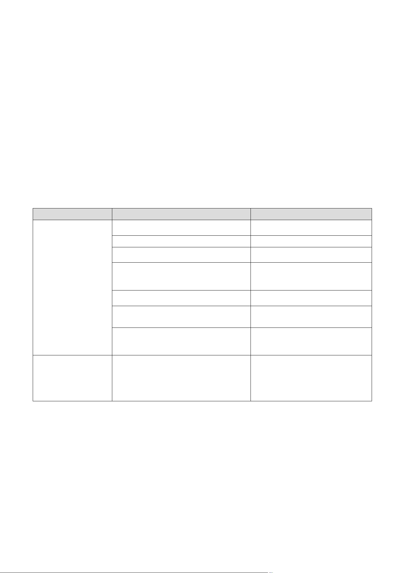
5.3 Detecting and rectifying faults
If problems occur whilst operating your boiler, you can
carry out the following self-checks:
Problem Possible cause Solution
No hot water,
heating stays cold;
boiler does not start
Building gas isolator cock closed
Open building gas isolator cock (¬ sec-
tion 4.6.1)
Building power supply switched off Switch on building power supply
Mains switch on boiler switched off
Switch on the mains switch on the boiler
(¬ section 4.6.2)
The heating flow temperature is set too low or in the
"Heating off" position (¬ section 4.7.2) and/or the
hot water temperature is too low
Set the heating flow temperature to the
desired temperature (¬ section 4.7) and/or
set the domestic hot water temperature to the
desired temperature (¬ section 4.8)
Filling pressure of the heating installation too low
Top up the heating installation with water
(¬ section 4.6.4)
Air in the heating installation
Purge the radiators;
If the problem occurs again:
Contact your competent person
Ignition malfunction
Press the reset button;
If the problem occurs again:
Contact your competent person
(¬ section 5.5).
DHW mode without any prob-
lems;
Heating does not start
No heat requirement via the controller
Check the timer programme on the controller
and correct if necessary;
Check the room temperature and, if required,
correct the target room temperature
(¬section4.9; Controller operating instruc-
tions).
5.1 Detecting and rectifying faults
> If, after checking the points mentioned in Table 5.1, your
boiler still shows signs of a fault, contact your competent
person to eliminate the problem.
Troubleshooting
Operating instructions ecoTEC plus 0020134822_01 19
5
5.4 Rectifying low water pressure
b
Caution.
Tap water that is extremely calciferous
or corrosive or contaminated by chemi-
cals can cause material damage.
Unsuitable tap water damages the seals
and diaphragms, blocks components in the
boiler and heating installation through
which the water flows and causes noise.
> Only fill the heating installation with suit-
able heating water.
> In case of doubt, consult your competent
person.
0,7bar
5.2 Display of the filling pressure for the heating installation is
too low
If the filling pressure for the heating installation falls below
0.08MPa (0.8 bar), the red bar display and the current fill-
ing pressure flash in the display.
If the pressure falls below 0.05 MPa (0.5 bar), the boiler
switches off and the fault message F.22 appears in the dis-
play. To restart the boiler, you must refill the heating instal-
lation with treated water (¬section4.6.3 and 4.6.4).
As soon as the system has been topped up with sufficient
water, the message disappears automatically after approx.
20 seconds. If the pressure drops frequently,the reason for
the loss of hot water must be identified and eliminated
> Contact your competent person.
If the heating installation extends over several storeys, a
higher filling pressure may be required for the heating
installation.
> Ask your competent person for details about this.
To fill up and to re-fill the heating installation, you can nor-
mally use tap water. In exceptional cases, however, the
water quality may not be suitable for filling the heating
installation because the water is highly corrosive or calcif-
erous.
> If this is the case, contact your competent person.
5.5 Resolving ignition faults
b
Caution.
Risk of damage due to improper modifi-
cations.
Improper modifications or persistent faults
can result in material damage.
> If you are unable to resolve the ignition
problem yourself by resetting the boiler
three times, consult your competent per-
son.
F. 2 8
Failure in start up
Igntn unsuccessful
1
2
3
5.3 Fault clearance
If the burner fails to ignite after five attempts, the boiler
will not operate and switches to "Fault". This is indicated by
the display of fault codes "F.28" or "F.29" (1) and an accom-
panying plain text display in the display., e.g. for F.28: "Fail-
ure during start-up, Ignition failed" (2).
On Vaillant ecoTEC plus boilers, a crossed-out flame symbol
is also displayed along with the relevant plain text in the
display, e. g. for F.28:
"Failure in start up: Igntn unsuccessful" (2). The boiler will
only ignite automatically again once you have reset it man-
ually.
> To reset the boiler manually, press the reset button (3)
and hold for one second.
Auxiliary functions
20 Operating instructions ecoTEC plus 0020134822_01
6
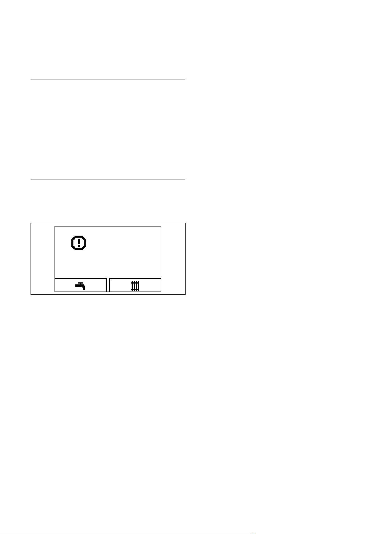
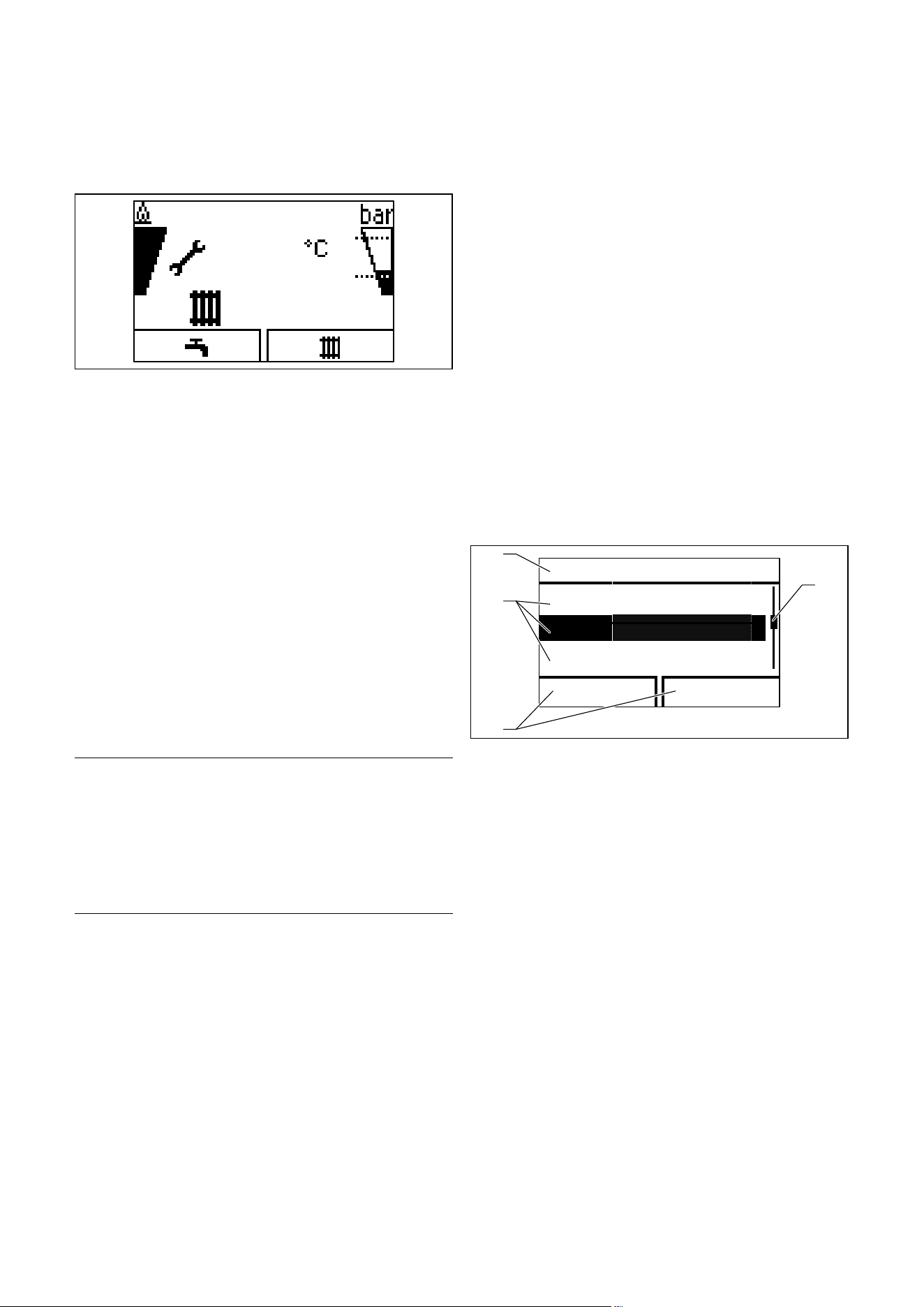
5.6 Service message
58
5.4 Service message
If the open-ended spanner is displayed, the boiler requires a
service.
> Consult your competent person about doing this.
The boiler is not in fault mode but continues to operate.
> In the "Live monitor", you can read further information
about the reason for the service (¬section 6.2).
> If your boiler shows that it is working in the Comfort
safety mode, contact your approved competent person.
> Inform the approved competent person of the status
code that is displayed.
i
If the water pressure is shown flashing at the
same time (¬section5.4), you only have to top
up the water (¬section4.6.3 and 4.6.4).
5.7 Resolving faults in the air/flue gas duct
a
Danger!
Risk of injury and material damage
resulting from improper modifications!
Improper modifications can affect the oper-
ating safety of your boiler.
> Never attempt to perform repairs on
your boiler by yourself.
> Always employ a competent person.
The boilers are fitted with a fan. If the fan does not work
properly, the boiler will switch itself off.
The fault message "F.32" appears in the display. The dis-
played fault code is additionally explained by a correspond-
ing plain text message in the display: "Fault: Fan".
6 Auxiliary functions
The digital information and analysis system provides you
with further functions via the menu.
6.1 Operation in the menu
You can access this menu by pressing both selector buttons
("i") at the same time.
6.1.1 Structure of the menu
In addition to the direct operation via the selector buttons
from the basic display menu, the digital information and
analysis system has a menu that, in turn, has two selection
levels (sublevels).
Through the selection levels, you navigate to the display
and setting levels in which you can read or change settings.
The selection levels have four display fields.
Menu
Water pressure
Live Monitor
Information
Back Select
1
4
2
3
6.1 Display fields in the menu
Key
1 Scroll bar (only if there are more list entries than can be shown
at once on the display)
2 Current functions of the right and left-hand selector buttons
(soft key functions)
3 List entries for the selection levels
4 Name of the selection level
i
In the following, path details at the beginning of
an instruction specify how to access this func-
tion, e.g. Menu ¬Information ¬Contact data.
Auxiliary functions
Operating instructions ecoTEC plus 0020134822_01 21
6
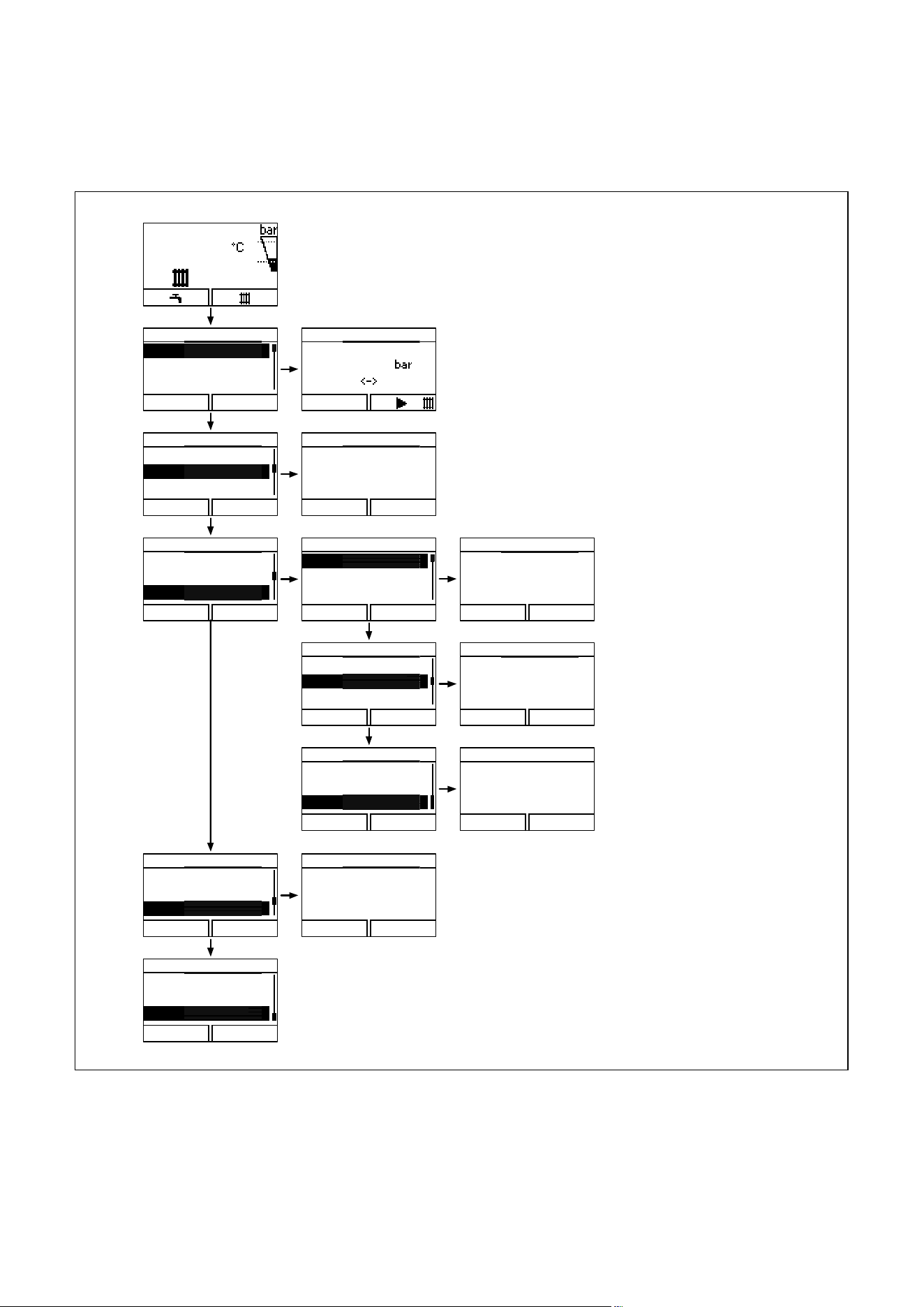
6.1.2 Overview of the menu structure
Menu
Installer level
Reset burner off time
Information
Back Select
Cancel Ok
Display contrast
20
Serial number
21 10 43
0001000033NO
0010011621
Back
Menu
Water pressure
Live Monitor
Information
Back Select
Menu
Water pressure
Live Monitor
Information
Back Select
Menu
Water pressure
Live Monitor
Information
Back Select
Menu
Live Monitor
Reset burner off time
Information
Back Select
Information
Contact data
Serial number
Back Select
Display contrast
Information
Contact data
Serial number
Back Select
Display contrast
Contact data
0219118
Back
Information
Contact data
Serial number
Back Select
Display contrast
50
1,0
Water pressure
Back
0,8 6,0
S.00
Heating
no heat requirement
Back
Reset Burner off time
Currnt burner off time
0 min
Back
6.2 Overview of the menu structure
Auxiliary functions
22 Operating instructions ecoTEC plus 0020134822_01
6
6.2 Displaying the Live monitor
(current status of the boiler)
S.04
Heating mode
burner on
Back
6.3 Live monitor (current status of the boiler, example)
Menu ¬Live Monitor
This function allows you to display the current status of
your boiler. In addition, the meaning of the message is dis-
played as plain text.
The display is automatically updated if the boiler status
changes.
Status codes Meaning
Displays in Heating mode
S 00 Heating mode: No heat demand
S 02 Heating mode: Water pump running
S 03 Heating mode: Ignition sequence
S 04 Heating mode: Burner ignited
S 06 Heating mode: Fan overrun
S 07 Heating mode: Pump overrun
S 08
Heating mode: Remaining anti-cycling time xx
min
Displays in cylinder charging mode
S 20 Warmstart demand
S 22 DHW mode: Pump running
Special cases
S 31 No heat demand, summer operating mode
S 34 Heating mode: frost protection
6.1 Status codes and their meaning (selection)
6.3 Setting the display contrast
Back
Display contrast
20
6.4 Setting the display contrast
Menu ¬Information ¬Display contrast
Using this function, you can set the display contrast in rela-
tion to the brightness of the surroundings to ensure that
the display is clearly legible.
6.4 Setting the language
Language
02 English
Cancel
Ok
6.5 Setting the language
Your competent person should have set the boiler to your
desired language. If you wish to set another language, you
can proceed as follows:
> Press and hold the right-hand selector button
and the plus button
at the same time.
> Also press the fault clearance key briefly.
> Continue to press and hold the right-hand selector but-
ton
and the plus button until the
display offers you the option to set the language.
> Use the minus button
or plus button
to select your desired language.
> Confirm the change by pressing the right-hand selector
button
("OK").
You must confirm the set language twice to ensure that you
have not accidentally set an incorrect language.
i
If you have accidentally set a language that you
cannot understand, you can change this as
described above.
Service
Operating instructions ecoTEC plus 0020134822_01 23
7
> Use the minus button or plus button
to scroll until your language appears.
6.5 Displaying contact data for the competent
person
Contact data
0219118
Back
6.6 Displaying contact data
Menu ¬Information ¬Contact data
If your competent person has entered their telephone
number during the installation, you can read this data
under "Contact data".
6.6 Displaying the serial number and article
number
Menu ¬Information ¬Serial number
"Serial number" shows the serial number of the boiler,
which the approved competent person may require from
you.
The article number is found in the second line of the serial
number.
The serial numbers are also located on a plate, which is
stuck behind the front flap on the underside of the boiler in
a plastic fish plate.
6.7 Reset burner off time
(resetting burner anti-cycling time)
Menu structure ¬Reset burner off time
i
This function must only be operated by your
competent person.
7 Service
a
Danger!
Risk of injury and material damage due
to incorrect maintenance and repairs!
If maintenance is not carried out, or it is
carried out incorrectly, this may adversely
affect the operational reliability of your
boiler.
> Never attempt to carry out maintenance
work or repairs on your boiler by your-
self.
> Always employ a competent person.
7.1 Servicing the boiler
Permanent operational readiness and safety, reliability and
a long working life require inspections and maintenance
work to be carried out annually on the boiler by a compe-
tent person.
Regular servicing ensures maximum efficiency and a more
economical operation of your boiler.
We recommend making a maintenance agreement.
7.2 Caring for your boiler
b
Caution.
Unsuitable cleaning agents can cause
damage.
Unsuitable cleaning agents (scouring or
other cleaning agents) can damage the
exterior, the fittings or the controls.
> Do not use sprays, solvents or cleaning
agents containing chlorine.
> Clean the exterior of your boiler with a damp cloth and a
little solvent-free soap. Do not use any detergent.

24 Operating instructions ecoTEC plus 0020134822_01
8 Decommissioning
8 Decommissioning
> Contact a competent person to disconnect the boiler
permanently.
8.1 Disposing of the boiler
Do not dispose of your Vaillant ecoTEC plus boiler or any of
its accessories in the household waste.
> Make sure the old unit and any accessories are disposed
of properly.
> Observe valid national regulations.
8.2 Disposing of the packaging
Arrange for the competent person who installed the boiler
to dispose of the transport packaging.
9 Manufacturer's guarantee and Vaillant
customer services
9.1 Factory guarantee
Two year guarantee for ecoTEC plus appliances
Vaillant undertakes to rectify any manufacturing defect that
occurs within twenty-four months of the installation date.
For the 2nd year of the guarantee to be valid an annual
service must be carried out by a competent person
approved at the time by the Health and Safety Executive
one year after installation.
The cost of this annual service is not included in the guar-
antee.
Registering with us
Registration is simple. Just complete the Guarantee Regis-
tration Card and return to Vaillant within 30 days of instal-
lation. Your details will then be automatically registered
within the Vaillant scheme.
Note: No receipt will be issued.
Immediate help
If your Vaillant boiler develops a fault your first action
should be to contact your installer, as his professional
assessment is needed under the terms of our Guarantee. If
you are unable to contact your installer, phone Vaillant
Service Solutions: 0870 6060 777
9.2 Vaillant Service
To ensure regular servicing, it is strongly recommended
that arrangements are made for a Maintenance Agreement.
Please contact Vaillant Service Solutions
(0870 6060 777) for further details.

Glossary
Operating instructions ecoTEC plus 0020134822_01 25
10
10 Glossary
Air/flue gas duct
The air/flue gas duct consists of all components that route
combustion air to the boiler or flue gas away from the
boiler.
Burner
The burner on a gas-fired condensing boiler is the compo-
nent on whose surface the gas/air mix is control-burnt.
Calorific value
Unlike the heating value, the calorific value of a fuel
describes the total usable heat during combustion, based
on the quantity of fuel used, including the condensation
heat in the steam. Condensing boilers use this additional
condensation heat to achieve considerably higher efficiency
levels than conventional boilers.
Controller
The controller is the interface to the boiler, by means of
which you can adjust, for example, the room temperature,
the hot water temperature, the heating times or the night
set-back phase in accordance with your requirements and
wishes.
A distinction is made between room thermostat, weather
compensator and solar control.
Cylinder charging
Cylinder charging mode refers to the process of heating up
the cylinder. See also hot water generation.
Dew point
The dew point is the temperature at which steam turns to
liquid (condensation). The steam in the flue gas from the
boiler contains thermal energy, which can be released by
condensation. In gas-fired and oil-fired boilers using calo-
rific values, the flue gases are cooled so that the steam
condenses and the heat that it contains can be output into
the heating system.
eBUS
The abbreviation eBUS is short for
energyBUS.
The eBUS is a special cable system used in the heating
technology field, which is used for communication between
the heating technology components (e.g. controller, boiler,
vrnetDIALOG).
Frost protection
The frost protection function protects your heating installa-
tion and dwelling from frost damage. If the heating flow
temperature falls below 5°C when the on/off switch is on,
the boiler comes into operation and heats the circulating
water to 30°C.
Heating flow temperature
Your boiler heats water which is pumped through your
heating installation. The temperature of this hot water as it
leaves the boiler is referred to as the heating flow tempera-
ture.
Hot water generation
Your boiler heats the water in the domestic hot water cylin-
der to the selected target temperature. If the temperature
in the DHW cylinder falls by a specific amount, the water is
heated up again to the target temperature.
Legionella
Legionella are water-borne bacteria which can quickly prop-
agate and cause serious lung diseases. Legionella bacteria
occur wherever heated water provides the optimum condi-
tions for multiplication. Temporarily heating the water to
above 60 °C kills off legionella.
Room thermostat
A room thermostat continuously measures the room tem-
perature and compares it with the room temperature you
have set (target room temperature). This allows the heating
installation to maintain a constant set temperature in your
room.
In addition, you can enter individual heating times. The tar-
get room temperature and the heating times set by you
control the operation of your boiler, the power of which is
adapted automatically to the respective heat demand.
vrnetDIALOG Internet communication system
-vrnetDIALOG is a service connection to the Internet. Using
vrnetDIALOG, your competent person can set the heating
installation in your house from your PC. Fault diagnosis can
also be carried out remotely via the integrated DIA system.
-vrnetDIALOG can also forward fault messages by fax,
e-mail or SMS to your competent person. This allows the
competent person to prepare in advance of carrying out
any work, if a repair is required, and to arrive with the right
spare parts on the service date.
If necessary, your competent person can also carry out
adjustments on the controller or boiler via vrnetDIALOG to
save unnecessary visits.
Weather compensator:
A weather compensator is a controller that controls the
heating flow temperature of the heating installation,
depending on the measured outside temperature.
With the weather compensator, you can also enter individ-
ual heating times. The outside temperatures that are meas-
ured and the heating times that are set control the opera-
tion of the burner, the output of which is adjusted automati-
cally to the relevant heat demand.

Index
26 Operating instructions ecoTEC plus 0020134822_01
Index
A
Air/flue gas duct ......................................................................... 25
Air/flue gas pipe .......................................................................... 20
Anti-legionella function .............................................................. 14
B
Burner anti-cycling time ............................................................. 9
C
CE label ............................................................................................ 3
Controller ........................................................................... 8, 14, 25
Controls ........................................................................................... 8
Customer service .................................................................... 5, 24
D
Decommissioning ........................................................................ 24
Display ...................................................................... 8, 11, 13, 15, 22
Disposal ......................................................................................... 24
F
Fault ................................................................................... 18, 19, 20
Fault clearance ............................................................................. 19
Fault codes .................................................................................... 17
Filling .............................................................................................. 12
Filling pressure ............................................................................. 12
Filling the heating installation .................................................. 12
Flue gas ............................................................................................ 5
Flue gas smell ................................................................................. 5
Frost
Activating the frost protection function ........................... 16
Draining the heating installation ........................................ 16
Protecting the heating installation against frost ........... 16
H
Heating flow temperature ......................................................... 13
Hot water
Drawing hot water .................................................................... 7
Setting the hot water temperature .................................... 14
Hot water generation ............................................ 7, 11, 14, 15, 25
Hot water temperature....................................................... 5, 7, 14
I
Identification plate ........................................................................ 3
If you smell gas .............................................................................. 5
Ignition ..................................................................................... 19, 22
Intended use .................................................................................. 4
Isolator devices ............................................................................. 11
L
Low water pressure ..................................................................... 19
S
Status displays ............................................................................. 17
Summer mode ....................................................................... 15, 22
Switching off
Boiler ......................................................................................... 15
Hot water generation ............................................................ 14
Switching off the boiler .............................................................. 15
Switching on
Boiler .......................................................................................... 11
Frost protection function ...................................................... 16
Power supply ........................................................................... 18
Switching on the boiler ............................................................... 11
T
Temperature
Hot water temperature ......................................................... 14
Troubleshooting ........................................................................... 17
V
Vaillant customer service ..................................................... 5, 24
Brief operating instructions
For detailed information, please read the corresponding
section in these installation instructions.
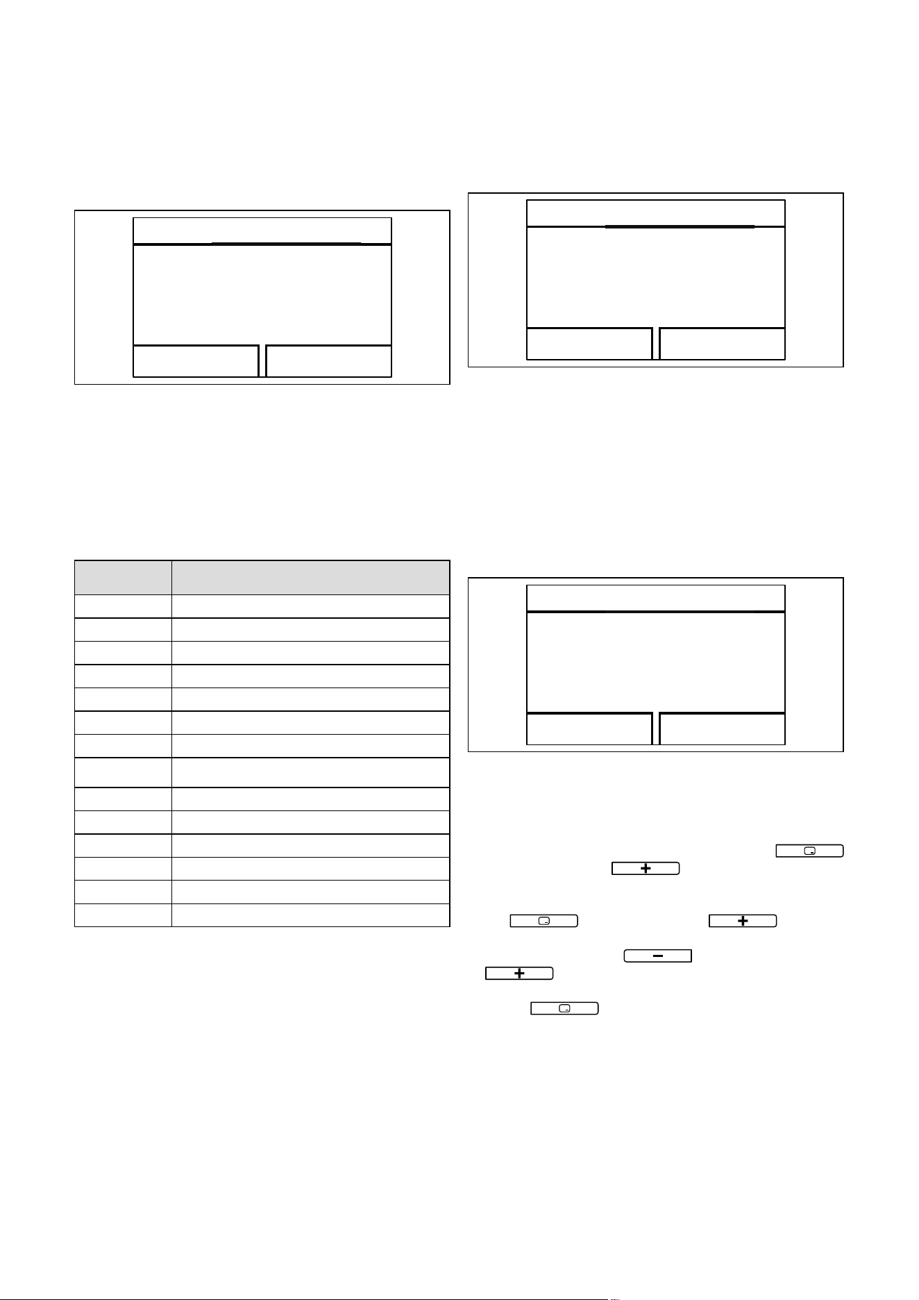
1. Switching off Heating mode (Summer mode) (¬ section 4.10.2)
50 50
Target flow temp.
Back
Heating off
Target flow temp.
Cancel Ok
> Right-hand selector but-
ton "
"
> –-Button to "Heating off" > Confirm "OK"
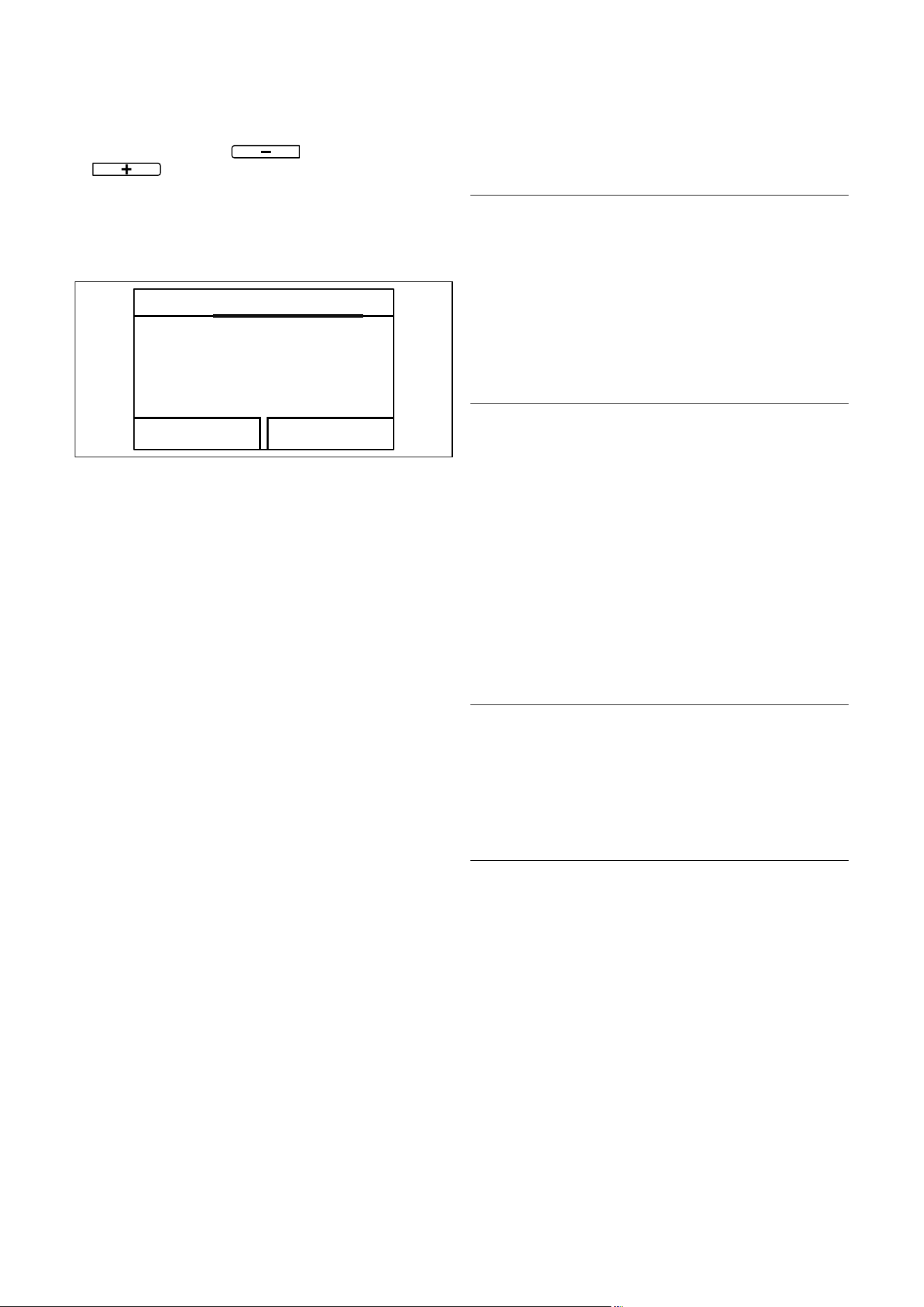
2. Setting the heating temperature (switching on Heating mode)
(¬ section4.7.1)
50
50
Target flow temp.
Back
48
Target flow temp.
Cancel Ok
> Right-hand selector but-
ton "
"
> +/– button for selecting
the temperature
> Confirm "OK"
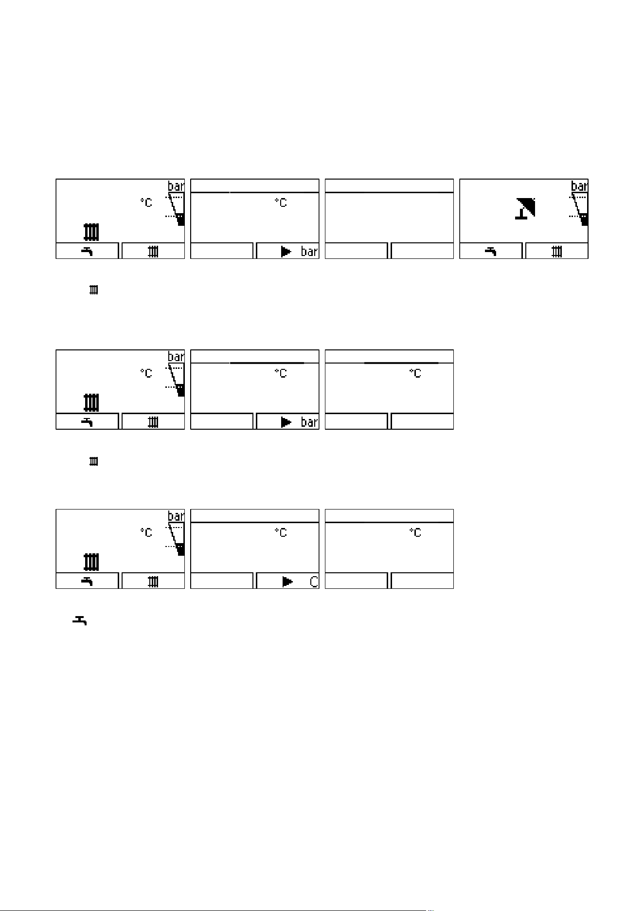
3. Setting the hot water temperature (¬ section 4.8)
50 45
DHW temperature
Back
48
DHW temperature
Cancel Ok
> Left-hand selector button
"
"
> +/– button for selecting
the temperature
> Confirm "OK"
0020134822_01 GBIE 062012 – Subject to change
Manufacturer
Supplier