
February 2012, Rev.3, 11/14
© 2012-2014 Fluke Corporation. All rights reserved.
Specifications are subject to change without notice.
All product names are trademarks of their respective companies.
Ti90, Ti95
Ti100, Ti105, Ti110, Ti125
TiR105, TiR110, TiR125
Performance Series Thermal Imagers
Users Manual
1.888.610.7664 sales@GlobalTestSupply.com
Fluke-Direct.com

LIMITED WARRANTY AND LIMITATION OF LIABILITY
Each Fluke product is warranted to be free from defects in material and workmanship under normal
use and service. The warranty period is two years and begins on the date of shipment. Parts, product
repairs, and services are warranted for 90 days. This warranty extends only to the original buyer or
end-user customer of a Fluke authorized reseller, and does not apply to fuses, disposable batteries, or
to any product which, in Fluke's opinion, has been misused, altered, neglected, contaminated, or
damaged by accident or abnormal conditions of operation or handling. Fluke warrants that software
will operate substantially in accordance with its functional specifications for 90 days and that it has
been properly recorded on non-defective media. Fluke does not warrant that software will be error free
or operate without interruption.
Fluke authorized resellers shall extend this warranty on new and unused products to end-user
customers only but have no authority to extend a greater or different warranty on behalf of Fluke.
Warranty support is available only if product is purchased through a Fluke authorized sales outlet or
Buyer has paid the applicable international price. Fluke reserves the right to invoice Buyer for
importation costs of repair/replacement parts when product purchased in one country is submitted for
repair in another country.
Fluke's warranty obligation is limited, at Fluke's option, to refund of the purchase price, free of charge
repair, or replacement of a defective product which is returned to a Fluke authorized service center
within the warranty period.
To obtain warranty service, contact your nearest Fluke authorized service center to obtain return
authorization information, then send the product to that service center, with a description of the
difficulty, postage and insurance prepaid (FOB Destination). Fluke assumes no risk for damage in
transit. Following warranty repair, the product will be returned to Buyer, transportation prepaid (FOB
Destination). If Fluke determines that failure was caused by neglect, misuse, contamination, alteration,
accident, or abnormal condition of operation or handling, including overvoltage failures caused by use
outside the product’s specified rating, or normal wear and tear of mechanical components, Fluke will
provide an estimate of repair costs and obtain authorization before commencing the work. Following
repair, the product will be returned to the Buyer transportation prepaid and the Buyer will be billed for
the repair and return transportation charges (FOB Shipping Point).
THIS WARRANTY IS BUYER'S SOLE AND EXCLUSIVE REMEDY AND IS IN LIEU OF ALL OTHER
WARRANTIES, EXPRESS OR IMPLIED, INCLUDING BUT NOT LIMITED TO ANY IMPLIED
WARRANTY OF MERCHANTABILITY OR FITNESS FOR A PARTICULAR PURPOSE. FLUKE
SHALL NOT BE LIABLE FOR ANY SPECIAL, INDIRECT, INCIDENTAL, OR CONSEQUENTIAL
DAMAGES OR LOSSES, INCLUDING LOSS OF DATA, ARISING FROM ANY CAUSE OR THEORY.
Since some countries or states do not allow limitation of the term of an implied warranty, or exclusion
or limitation of incidental or consequential damages, the limitations and exclusions of this warranty
may not apply to every buyer. If any provision of this Warranty is held invalid or unenforceable by a
court or other decision-maker of competent jurisdiction, such holding will not affect the validity or
enforceability of any other provision.
Fluke Corporation
P.O. Box 9090
Everett, WA 98206-9090
U.S.A.
Fluke Europe B.V.
P.O. Box 1186
5602 BD Eindhoven
The Netherlands
11/99
To register your product online, visit http://register.fluke.com
.
1.888.610.7664 sales@GlobalTestSupply.com
Fluke-Direct.com

i
Table of Contents
Title Page
Introduction ................................................................................ 1
How to Contact Fluke ................................................................. 2
Safety Information ...................................................................... 3
Radio Frequency Data ............................................................... 5
Accessories ................................................................................ 7
Before You Start ......................................................................... 8
How to Charge the Battery ..................................................... 9
Two-Bay Battery Charger Base........................................... 9
On-Imager AC Power Socket .............................................. 9
Optional 12 V Vehicle Charger ............................................ 10
Power On and Off ................................................................... 10
Features and Controls ................................................................ 11
Focus ......................................................................................... 13
Primary and Secondary Triggers ................................................ 14
How to Use the Control Buttons ................................................. 15
How to Use the Menus ............................................................... 15
Image Capture ........................................................................... 17
IR-PhotoNotes™..................................................................... 17
Voice Annotation..................................................................... 18
Listen to a Voice Annotation ................................................... 18
Edit Data Files ........................................................................ 19
Save Data Files ...................................................................... 19
SD Memory Card ....................................................................... 20
Temperature Measurement ........................................................ 21
SmartView
Software ................................................................. 22
Menus ........................................................................................ 22
Measurement Menu ................................................................ 22
Range ................................................................................. 23
Emissivity Adjustment ......................................................... 26
Reflected Background Temperature Compensation ........... 28
TiR-Mode ............................................................................ 29
Transmission/Transmittance Adjustment ............................ 30
1.888.610.7664 sales@GlobalTestSupply.com
Fluke-Direct.com

Ti90, Ti95, Ti100, Ti105, Ti110, Ti125, TiR105, TiR110, TiR125
Users Manual
ii
Spot Temperatures .............................................................. 31
User-Definable Spot Markers .............................................. 32
Center Box........................................................................... 33
Image Menu ............................................................................ 34
Palette ................................................................................. 34
IR-Fusion
®
........................................................................... 36
Color Alarm (Temperature Alarm) ....................................... 37
Set High-Temperature Color Alarm ................................. 38
Set Low-Temperature/Dew Point Color Alarm ................ 39
Outside/Inside Alarm ....................................................... 39
Display Graphics Presentation ............................................ 40
Camera Menu ......................................................................... 41
Compass ............................................................................. 41
Video ................................................................................... 42
Video Recording .............................................................. 43
Video Playback ............................................................... 43
Laser Pointer ....................................................................... 44
LED Light (Torch) ................................................................ 45
Backlight .............................................................................. 45
Fluke Connect™ Wireless System ...................................... 46
CNX™ Wireless System ...................................................... 47
Memory Menu ......................................................................... 48
Review Data Files ................................................................ 48
Delete Data Files ................................................................. 49
Settings Menu ......................................................................... 50
Units .................................................................................... 50
File Format .......................................................................... 50
Auto Off ............................................................................... 52
Date ..................................................................................... 53
Time .................................................................................... 54
Language ............................................................................ 55
Imager Information .............................................................. 55
Maintenance ............................................................................... 56
How to Clean the Case ........................................................... 56
Battery Care ............................................................................ 57
General Specifications ................................................................ 58
Detailed Specifications ............................................................... 60
1.888.610.7664 sales@GlobalTestSupply.com
Fluke-Direct.com

iii
List of Tables
Table Title Page
1. Symbols ..................................................................................... 6
2. Accessories ................................................................................ 7
3. Packing Lists .............................................................................. 8
4. Features and Controls ................................................................ 11
5. Overview of Controls .................................................................. 15
6. Menu Overview .......................................................................... 16
7. Palettes ...................................................................................... 35
8. Infrared and IR-Fusion Modes by Model .................................... 36
List of Figures
Figure Title Page
1. Lens Cover Laser Warning ......................................................... 3
2. IR-OptiFlex Focus ...................................................................... 13
3. SD Memory Card Insertion and Removal ................................... 20
4. Level and Span Settings ............................................................ 25
1.888.610.7664 sales@GlobalTestSupply.com
Fluke-Direct.com

Ti90, Ti95, Ti100, Ti105, Ti110, Ti125, TiR105, TiR110, TiR125
Users Manual
iv
1.888.610.7664 sales@GlobalTestSupply.com
Fluke-Direct.com

1
Introduction
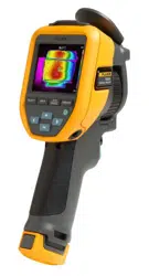
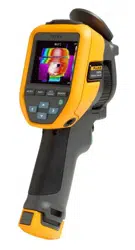
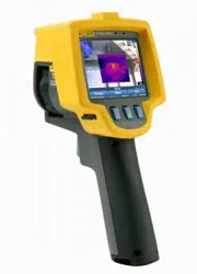
The Fluke Ti90, Ti95, Ti100, Ti105, Ti110, Ti125, TiR105, TiR110, and TiR125
Thermal Imagers (the Product or Imager) are handheld, infrared imaging
cameras for use in many applications. These applications include equipment
troubleshooting, preventive and predictive maintenance, and building
diagnostics. The Ti90, Ti95, and Ti100 are general-purpose Imagers. The
Ti105, Ti110, and Ti125 are for industrial-commercial maintenance
applications. The TiR105, TiR110 and TiR125 are optimized for building
inspection and diagnostics applications.
All Imagers display thermal images on a high-visibility LCD screen and can
save images to an SD memory card. Saved images and data can be
transferred to a PC via the SD memory card or by a direct USB connection to
the PC.
Fluke SmartView
®
software supports all Imager models. This software is a high-
performance, professional software suite that allows for analysis and reporting.
SmartView is available for free download at www.fluke.com/smartviewdownload.
Depending on the model, the Voice Annotation and IR-PhotoNotes™ features
are also available.
Infrared images display in different color palettes on each Imager. The
temperature measurement range is:
• Ti90, Ti95, Ti100, Ti105, Ti110 -20 °C to +250 °C
• Ti125 -20 °C to +350 °C
• TiR105, TiR110, TiR125 -20 °C to +150 °C
A rugged, rechargeable lithium-ion smart battery provides power to the Imager.
Direct AC power is accessible with the included AC power adapter.
The Fluke Ti110, Ti125, TiR110, and TiR125 use the IR-OptiFlex™ focus
system. IR-OptiFlex keeps the Imager in good focus at distances more than
four feet. It also allows the flexibility of one-touch manual focus to fine tune the
image in close-up situations. The Fluke Ti90, Ti95, Ti100, Ti105, and TiR105
use a focus-free system with a large depth of field that keeps the image in good
focus at distances more than four feet.
1.888.610.7664 sales@GlobalTestSupply.com
Fluke-Direct.com

Ti90, Ti95, Ti100, Ti105, Ti110, Ti125, TiR105, TiR110, TiR125
Users Manual
2
How to Contact Fluke
To contact Fluke, call one of the following telephone numbers:
• USA: 1-800-760-4523
• Canada: 1-800-36-FLUKE (1-800-363-5853)
• Europe: +31 402-675-200
• Japan: +81-3-6714-3114
• Singapore: +65-6799-5566
• Anywhere in the world: +1-425-446-5500
Or, visit Fluke's website at www.fluke.com.
To register your Product, visit register.fluke.com.
To view, print, or download the latest manual supplement, visit
us.fluke.com/usen/support/manuals.
To download SmartView
software visit www.fluke.com/smartviewdownload.
To download the Fluke Connect app, go to iTunes or Google app store and
download Fluke Connect.
1.888.610.7664 sales@GlobalTestSupply.com
Fluke-Direct.com
Performance Series Thermal Imagers
Safety Information
3
Safety Information
A Warning identifies hazardous conditions and actions that could cause bodily
harm or death. A Caution identifies conditions and actions that could damage
the Product or cause permanent loss of data.
Warning
To prevent eye damage and personal injury:
• Do not look into the laser. Do not point laser directly at
persons or animals or indirectly off reflective surfaces.
• Do not look directly into the laser with optical tools (for
example, binoculars, telescopes, microscopes). Optical tools
can focus the laser and be dangerous to the eye.
• Use the Product only as specified or hazardous laser
radiation exposure can occur.
• Do not open the Product. The laser beam is dangerous to
eyes. Have the Product repaired only through an approved
technical site.
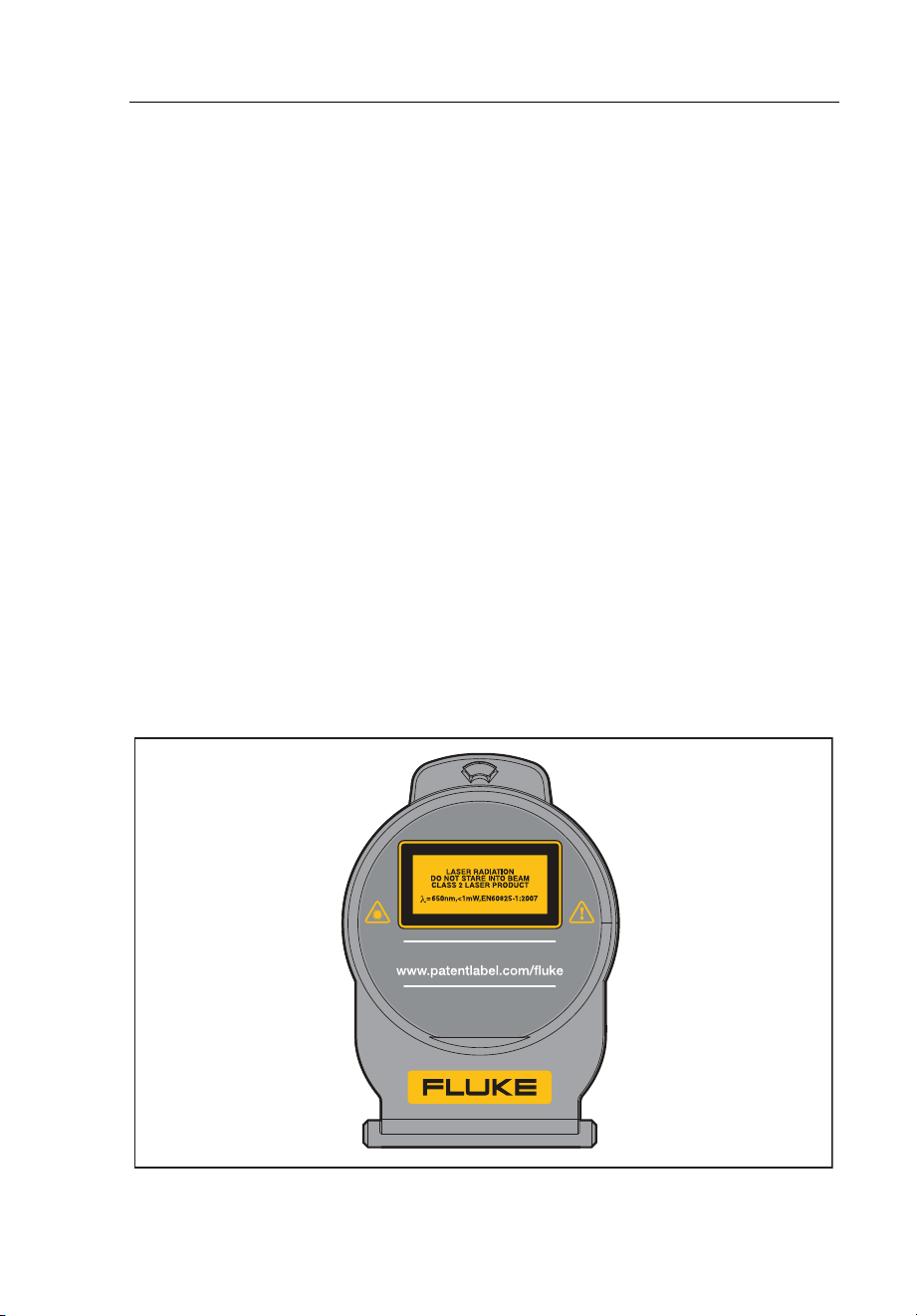
Additional laser warning information is on the inside of the Product lens cover,
see Figure 1.
gju05.eps
Figure 1. Lens Cover Laser Warning
US PAT.
IC: 6627A-F125
FCC ID: T68-F125
1.888.610.7664 sales@GlobalTestSupply.com
Fluke-Direct.com

Ti90, Ti95, Ti100, Ti105, Ti110, Ti125, TiR105, TiR110, TiR125
Users Manual
4
Warning
To prevent personal injury:
• Read all safety information before you use the Product.
• Carefully read all instructions.
• Use the Product only as specified, or the protection supplied by the
Product can be compromised.
• Replace the batteries when the low battery indicator shows to
prevent incorrect measurements.
• Do not use the Product around explosive gas.
• Do not use the Product if it operates incorrectly.
• Do not use the Product if it is damaged.
• Disable the Product if it is damaged.
• See emissivity information for actual temperatures. Reflective
objects result in lower than actual temperature measurements.
These objects pose a burn hazard.
• Do not disassemble the battery.
• Use only Fluke approved power adapters to charge the battery.
• Do not disassemble or crush battery cells and battery packs.
• Use only specified replacement parts.
• Have an approved technician repair the Product.
1.888.610.7664 sales@GlobalTestSupply.com
Fluke-Direct.com

Performance Series Thermal Imagers
Radio Frequency Data
5
Radio Frequency Data
Note
• Changes or modifications to the wireless 2.4 GHz radio not
expressly approved by Fluke Corporation could void the user's
authority to operate the Product.
• This section does not apply to the Ti90 and Ti95 models.
This Product complies with Part 15 of the FCC Rules. Operation is subject to
the two conditions that follow:
1. This Product cannot cause interference.
2. This Product must accept any interference, including interference that can
cause undesired operation of the device.
Class B digital device: A digital device that is marketed for operation in a
residential environment not withstanding use in commercial, business and
industrial environments. Examples of such devices include, but are not limited
to, personal computers, calculators, and equivalent electronic devices that are
marketed for operation by the general public.
The Product was tested and found to comply with the limits for a Class B digital
device, pursuant to Part 15 of the FCC Rules. These limits are designed to
provide reasonable protection against harmful interference in a residential
installation. This equipment generates, uses, and can radiate radio frequency
energy and, if not installed and used in accordance with the instructions, can
cause harmful interference to radio communications. However, there is no
guarantee that interference will not occur in a particular installation. If this
equipment does cause harmful interference to radio or television reception,
which can be determined by turning the equipment off and on, the user is
encouraged to try to correct the interference by one or more of the measures
that follow:
• Reorient or relocate the receiving antenna.
• Increase the separation between the equipment and receiver.
• Consult the dealer or an experienced radio/TV technician for help.
The term "IC:" before the radio certification number only signifies the device
meets Industry's Canada technical specifications.
1.888.610.7664 sales@GlobalTestSupply.com
Fluke-Direct.com

Ti90, Ti95, Ti100, Ti105, Ti110, Ti125, TiR105, TiR110, TiR125
Users Manual
6
Table 1 is a list of symbols used on the Imager and in this manual.
Table 1. Symbols
Symbol Description Symbol Description
Battery status. Battery
charging when animated.
Connected to ac power.
Battery removed.
i
Audio indicator
Audio recording associated
with the displayed image.
p
Pause recording indicator
j
IR-PhotoNotes™ indicator
r
Video recording in process
k
Video file indicator
On/Off Symbol.
Sleep mode.
Important information.
See manual.
Warning. Laser.
Conforms to relevant
Australian standards.
Conforms to relevant
Canadian and US
standards.
Conforms to relevant
South Korean EMC
standards.
Japan Quality Association
Conforms to requirements of European Union and European Free
Trade Association.
This Product contains a lithium-ion battery. Do not mix with the
solid waste stream. Spent batteries should be disposed of by a
qualified recycler or hazardous materials handler per local
regulations. Contact your authorized Fluke Service Center for
recycling information.
This product complies with the WEEE Directive (2002/96/EC)
marking requirements. The affixed label indicates that you must not
discard this electrical/electronic product in domestic household
waste. Product Category: With reference to the equipment types in
the WEEE Directive Annex I, this product is classed as category 9
“Monitoring and Control Instrumentation” product. Do not dispose
of this product as unsorted municipal waste. Go to Fluke's website
for recycling information.
1.888.610.7664 sales@GlobalTestSupply.com
Fluke-Direct.com

Performance Series Thermal Imagers
Accessories
7
Accessories
Table 2 is a list of the accessories available for the Imager.
Table 2. Accessories
Model Description PN
FLK-TI-SBP3 Smart Battery Pack 3440365
FLK-TI-SBC3 Charging Base/Power Supply with Adapters 3440352
TI-CAR CHARGER 12 V Vehicle Charger Adapter 3039779
FLK-TI-VISOR2 Sun Visor 3996500
FLK-TI-TRIPOD2 Tripod Mounting Accessory 3996517
BOOK-ITP Introduction to Thermography Principles 3413459
FC-SD8GB
Fluke Connect™ Wireless SD Card
(where available)
4463628
1.888.610.7664 sales@GlobalTestSupply.com
Fluke-Direct.com

Ti90, Ti95, Ti100, Ti105, Ti110, Ti125, TiR105, TiR110, TiR125
Users Manual
8
Before You Start
Carefully unpack the items in Table 3.
Table 3. Packing Lists
Item
Ti90 Ti95
Ti100
Ti105
TiR105
Ti110
TiR110
Ti125 TiR125
Thermal Imager
• • • • • •
Two-Bay Battery Charge Base
• •
Lithium-ion Smart Battery
1 1 1 1 2 2
Hard Carrying Case
• • • •
USB Cable
• • • • • •
Fluke Connect™ Wireless SD
Card
[1]
• • • • • •
SD Memory Card
[2]
• • • • • •
Multi-format USB Memory Card
Reader
• •
Soft Transport Bag
• • • • • •
Adjustable Hand Strap (Left-
hand or Right-hand use)
• • • • •
Users Manuals
[3]
To view, print, or download the manual,
visit us.fluke.com/usen/support/manuals.
Quick Reference Card
• • • • • •
Warranty Registration Card
• • • • • •
[1] Fluke Connect is not available in all countries.
[2] Fluke recommends the SD memory card that is supplied with the Imager. Fluke
does not warrant the use or reliability of aftermarket SD memory cards of different
brands or capacities.
name and language preference in the subject line.
1.888.610.7664 sales@GlobalTestSupply.com
Fluke-Direct.com

Performance Series Thermal Imagers
Before You Start
9
How to Charge the Battery
Before you use the Imager for the first time, charge the battery for a minimum
of two and one-half hours. The battery status shows on the five-segment
charge indicator.
Note
New batteries are not fully charged. Two to ten charge/discharge
cycles are necessary before the battery charges to its maximum
capacity.
To charge the battery, use one of the options that follow:
Two-Bay Battery Charger Base
1. Connect the ac power supply to the ac wall outlet and connect the dc
output to the charger base.
2. Put one or two smart batteries into bays of charger base.
3. Charge batteries until charge indicators show “full.”
4. Remove smart batteries and disconnect the power supply when batteries
are fully charged.
On-Imager AC Power Socket
1. Connect the ac power adapter into an ac wall outlet and connect the dc
output to the Imager’s ac power socket. flashes in the upper left-hand
corner of the display while the battery charges with the ac power adapter.
2. Charge until the charge indicator on the display does not flash.
3. Disconnect ac power adapter when the smart battery is fully charged.
Note
Make sure that the Imager is near room temperature before you
connect it to the charger. See the charging temperature specification.
Do not charge in hot or cold areas. When you charge in extreme
temperatures, battery capacity may be decreased.
shows in the upper left-hand corner of the display when the Imager is
connected to ac power and the battery is removed. When the Imager’s power is
off and the ac power adapter is connected, flashes in the center of the
display to show that the battery charge is in process.
1.888.610.7664 sales@GlobalTestSupply.com
Fluke-Direct.com

Ti90, Ti95, Ti100, Ti105, Ti110, Ti125, TiR105, TiR110, TiR125
Users Manual
10
Keep the Imager attached to the charger until the battery condition icon shows
a full charge. If you remove the Imager from the charger before a full charge
shows, it may have a reduced run-time.
Note
When the battery is connected to ac power, or the unit is in video
mode, the Sleep Mode/Auto Off feature is disabled automatically.
Optional 12 V Vehicle Charger
1. Connect the 12 V adapter into the 12 V accessory socket of the vehicle.
2. Connect the output to the ac power socket of the Imager.
3. Charge until the indicator shows full on the screen.
4. Disconnect the 12 V adapter and Imager when battery is fully charged.
Caution
To prevent damage to the Imager, remove it from the DC car
charger before you start or jump start the vehicle.
Power On and Off
To turn the Imager on or off, push and hold the green Power button above
the LCD for two seconds, see Table 4. When the Auto Off feature is on, the
Imager goes into Sleep Mode after five minutes of inactivity and shows
on
the display. Press any key to restart the Imager. After 20 minutes of inactivity,
the Imager turns off. For information about how to set this feature, see page 52.
Note
All thermal imagers need sufficient warm-up time for the most
accurate temperature measurements and best image quality. This
time can often vary by model and by environmental conditions.
Although most imagers are fully warmed up in 3-5 minutes, it is always
best to wait a minimum of 10 minutes if the most accurate temperature
measurement is very important to your application. When you move
an Imager between environments with large differences in ambient
temperature, more adjustment time can be required.
1.888.610.7664 sales@GlobalTestSupply.com
Fluke-Direct.com
Performance Series Thermal Imagers
Features and Controls
11
Features and Controls
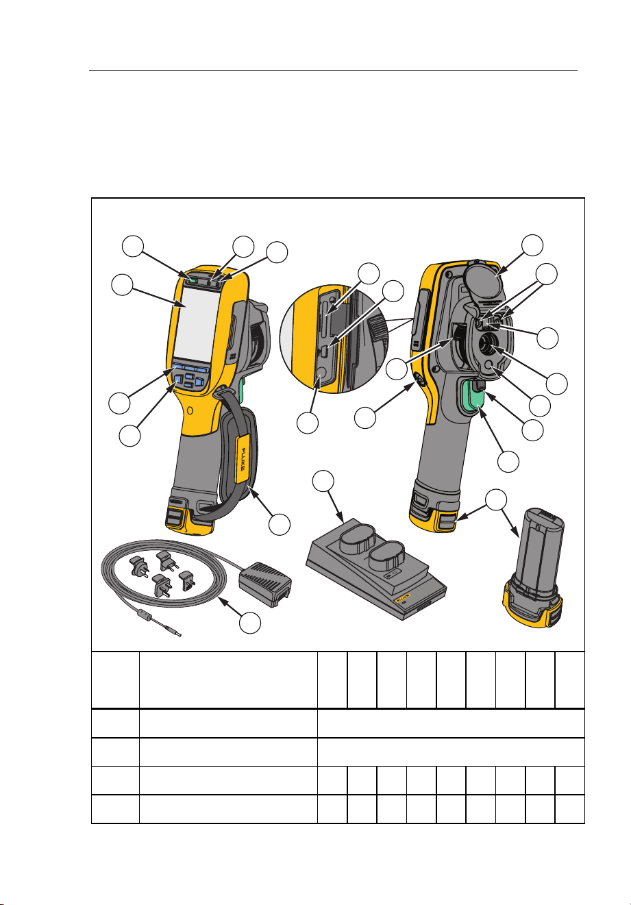
Features and controls for your Imager will vary by model. Use Table 4 as a
reference for the features that are included with your model.
Table 4. Features and Controls
POWER
Ti SBC3
SMART BATTERY
CHARGER 3
22
21
18
1
2
3
4
8
9
10
6
5
7
11
13
15
12
20
17
19
16
14
gju01.eps
Item Description
Ti90
Ti95
Ti100
Ti105
Ti110
Ti125
TiR105
TiR110
TiR125
LCD Display
All Models
Power On/Off
All Models
Speaker
• • • • • • •
Microphone
• • • • • • •
1.888.610.7664 sales@GlobalTestSupply.com
Fluke-Direct.com

Ti90, Ti95, Ti100, Ti105, Ti110, Ti125, TiR105, TiR110, TiR125
Users Manual
12
Table 4. Features and Controls (cont.)
Item Description
Ti90
Ti95
Ti100
Ti105
Ti110
Ti125
TiR105
TiR110
TiR125
Function Buttons
(F1, F2, and F3)
All Models
Arrow Buttons
All Models
Hand Strap
• • • • • • • •
SD Memory Card Slot
All Models
USB Cable Connection
All Models
AC Adapter/Charger Input
Terminal
All Models
Retractable Lens Cover
All Models
LED Light (Torch)
• • • • • •
Visual Camera and Lens • • • • • • • •
Infrared Camera Lens All Models
Laser Pointer • • • • • • •
Secondary Trigger • • • • • • •
Primary Trigger All Models
Hand Strap Anchor Post
(Right and Left)
All Models
IR-OptiFlex™ Focus
Control
• • • •
Lithium-ion Smart Battery All Models
2-Bay Battery Charging
Base
•
•
AC Power Adapter with
Universal Adapter
All Models
1.888.610.7664 sales@GlobalTestSupply.com
Fluke-Direct.com
Performance Series Thermal Imagers
Focus
13
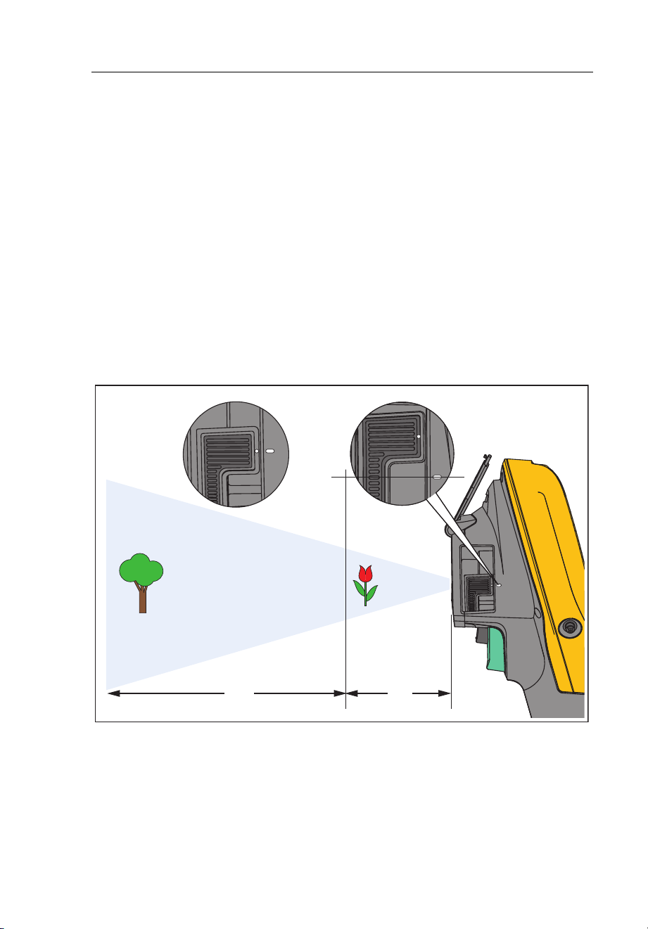
Focus
Models Ti110, Ti125, TiR110, and TiR125 have IR-OptiFlex focus. The Ti90,
Ti95, Ti100, Ti105, and TiR105 use a large depth of field focus-free system.
Models with IR-OptiFlex focus can operate in a focus-free mode, but also have
the flexibility for close focus situations (<122 cm/48 inches) with a one-touch,
fine-tune focus capability. See Figure 2.
The focus-free system can focus at a minimum distance of 122 cm (48 in) and
beyond with no adjustment.
Correct focus is important in all imaging applications. Correct focus makes sure
that the infrared energy is correctly directed onto the pixels of the detector.
Without the correct focus, the thermal image can be blurry and the radiometric
data will be inaccurate. Out-of-focus infrared images are frequently unusable or
of little value.
gju04.eps
Figure 2. IR-OptiFlex Focus
4 ft>4 ft
1.888.610.7664 sales@GlobalTestSupply.com
Fluke-Direct.com

Ti90, Ti95, Ti100, Ti105, Ti110, Ti125, TiR105, TiR110, TiR125
Users Manual
14
To operate the IR-OptiFlex focus in the focus-free mode, align the white dot on
the focus control with the white dot on the body of the Imager. You will also feel
a detent at this position. See Figure 2. In this mode, in addition to correctly
focused infrared images, the IR-Fusion must always be in proper alignment.
To operate with IR-OptiFlex focus in manual mode or to fine tune the focus,
turn the one-touch focus control in a clockwise or counterclockwise direction.
As you turn the focus control, you will see a live thermal image on the display
as it changes. When your target comes into focus, it shows a sharper image.
When the target moves out of focus, the image becomes blurry.
Primary and Secondary Triggers
The two-part trigger is located in the standard trigger position for a pistol-grip
device. The larger, green trigger is the primary trigger. The smaller, black
trigger is the secondary trigger.
In normal operation (video is off), the function of the primary trigger is to
capture a thermal image for possible storage to memory by the user. When
video is on, the primary trigger is the start/stop for video recording.
The secondary trigger operates the laser and LED light. For information about
how to enable the laser and torch, see pages 44 and 45.
Note
The secondary trigger does not apply to the Ti90 and Ti95 models.
1.888.610.7664 sales@GlobalTestSupply.com
Fluke-Direct.com

Performance Series Thermal Imagers
How to Use the Control Buttons
15
How to Use the Control Buttons
Three function buttons (, , ) and four arrow buttons (,
, , and ) are the primary controls. These buttons move the cursor
through the menu structure to set the features.
Table 5 is an overview of the buttons and their actions. In live Manual Mode,
the arrow buttons are always active to adjust Level and Span.
Table 5. Overview of Controls
Button Button Label / Action
, Trigger Cancel
, Trigger Done (exit from Menu structure)
, Select or OK
, Back
, Move cursor to highlight an option
, Fast forward/rewind (video mode only)
How to Use the Menus
The menus, coupled with the three function buttons (, , )
and arrow buttons, are the access for thermal image display, camera features,
memory review, and settings for date, time, language, units, file format, and
Imager information.
To open the primary menu, push or . The primary menu shows five
secondary menus for Measurement, Image, Camera, Memory, and Settings.
The text above each function button (, , ) applies to that
button throughout all menu screens.
Push to open the primary menu and push / to cycle through
the secondary menus. Each secondary menu lists an options menu. Push
/ to cycle through the options.
The primary, secondary, and option menus close 10 seconds after the last push
of a function button. The option selection menu stays open until you make the
selection, go up a menu level, or cancel the action. Table 6 is list of features by
model that you access through the menus.
1.888.610.7664 sales@GlobalTestSupply.com
Fluke-Direct.com

Ti90, Ti95, Ti100, Ti105, Ti110, Ti125, TiR105, TiR110, TiR125
Users Manual
16
Table 6. Menu Overview
Menu Features and Adjustments
Ti90
Ti95
Ti100
Ti105
Ti110
Ti125
TiR105
TiR110
TiR125
IR-PhotoNotes™
• •
• •
Voice Annotation
• •
• •
Level and Span All Models
Emissivity Selection All Models
Reflected Background Temperature
Compensation
All Models
Transmission Correction
• •
• •
Spot Temperatures (hot and cold spot
markers)
• • •
User-definable Spot Markers
• • • •
Expand/Contract Center Box (MIN/MAX/AVG)
• • • • • •
Fixed-Size Center Box (MIN/MAX/AVG)
•
Color Palettes All Models
IR-Fusion
®
• •
• • • • • •
Color Alarms (Temperature Alarms)
High Temperature
• • • • • •
Low Temperature (Dewpoint)
• •
• •
Isotherm
•
•
User-selectable Display Graphics All Models
Cardinal Compass
• •
• •
Laser Pointer (on/off)
• • • • • • •
LED Light (Torch)
• • • • • •
Fluke Connect™ Wireless System All Models
CNX™ Wireless System
• • • • • • •
User-selectable Temperature Scale (°C/°F) All Models
User-selectable File Format
.IS2, .JPG, .BMP
• • • • • • • • •
.IS3
• •
.AVI
• • • •
User-selectable Sleep/Auto Off All Models
Time and Date Settings All Models
Language Selection All Models
Center Point Temperature All Models
1.888.610.7664 sales@GlobalTestSupply.com
Fluke-Direct.com

Performance Series Thermal Imagers
Image Capture
17
Image Capture
Point the imager at the object or area of interest. Make sure that the object is in
focus. Pull and release the primary trigger. This will capture and freeze the
image. To cancel the captured image, pull the primary trigger again or
to return to the Live view.
Depending on the selected file format settings, the Imager shows the captured
image and a menu bar. The menu bar lets you save the image, edit some
image settings, and add voice annotation or IR-PhotoNotes. To change the file
format, see File Format on page 50.
IR-PhotoNotes™
IR-PhotoNotes™ are photograph annotations that allow the user to capture and
add multiple visible images of various objects, text, or other information that is
related to the analysis and reporting of an infrared image. Examples of an
annotation include motor name plates, printed information or warning signs,
larger views of the environment or room, and related equipment. Up to three
images can be captured with the visible image that is stored with the infrared
image as part of IR-Fusion technology. These visible images are only available
in the .is2 file format and are stored in the file so you do not need to collate
multiple files at a later time.
To add IR-PhotoNotes:
1. With an image in the buffer, push to open the EDIT IMAGE menu.
2. Push / to highlight IR-PhotoNotes.
3. Push to enter the Picture mode.
4. Focus Imager on the object and pull the primary trigger.
5. Push to continue.
6. Push save the picture with the image.
1.888.610.7664 sales@GlobalTestSupply.com
Fluke-Direct.com

Ti90, Ti95, Ti100, Ti105, Ti110, Ti125, TiR105, TiR110, TiR125
Users Manual
18
Voice Annotation
The maximum recording time is 60 seconds for each image reviewable
playback (varies by model).
To add a voice (audio) record:
1. With an image in the buffer, push to open the EDIT IMAGE menu.
2. Push / to highlight Add Audio.
3. Push to record up to 60 seconds of audio. The display updates to
show the recorded time.
4. Push to pause the recorder.
5. Push when done.
6. Push to review the audio file or to save the audio with the
image.
Listen to a Voice Annotation
The voice (audio) record replays through the speaker.
To playback an .is2 file on the SD memory card:
1. Do the steps in the Review Data Files section on page 48 to see the image
on the display.
2. Push .
3. Push or to set Audio.
4. Push to listen to the audio.
5. Push again to pause the audio.
1.888.610.7664 sales@GlobalTestSupply.com
Fluke-Direct.com

Performance Series Thermal Imagers
Image Capture
19
Edit Data Files
Before saving a file, you can edit or modify the image.
To edit:
1. With an image in the buffer, push to open the EDIT IMAGE menu.
2. Push / to highlight Edit Image.
3. Push to open the EDIT IMAGE menu.
4. Push / to highlight an option.
5. Push to save the changes with the file.
Save Data Files
To save an image as a data file:
1. Focus on the object of interest or inspection area.
2. Pull the trigger to capture the image. The image is now in the buffer and
you can save or edit.
3. Push to save the image as a file and go back to the live view.
1.888.610.7664 sales@GlobalTestSupply.com
Fluke-Direct.com
Ti90, Ti95, Ti100, Ti105, Ti110, Ti125, TiR105, TiR110, TiR125
Users Manual
20
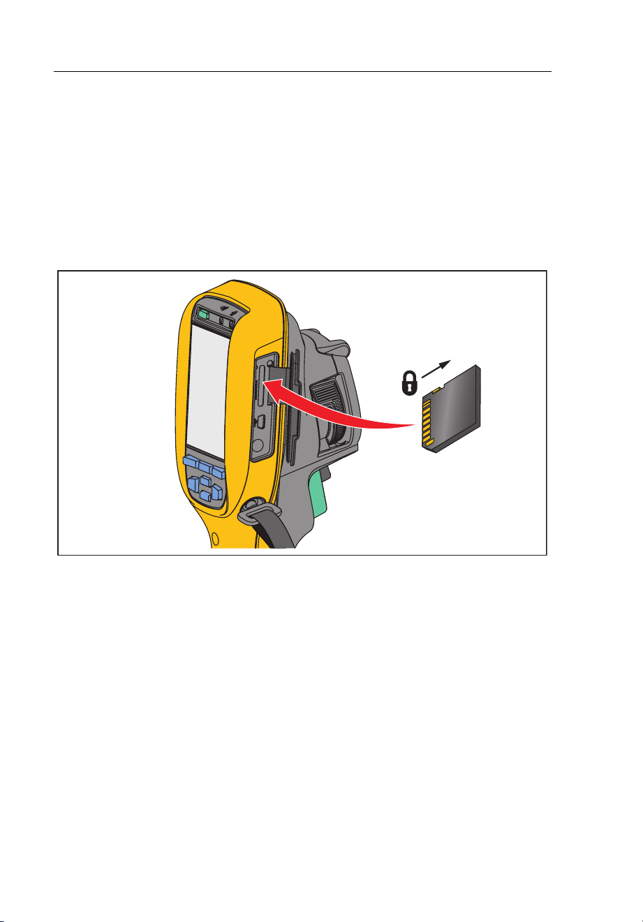
SD Memory Card
To eject an SD memory card, push in on the exposed edge of the card and
then release. The card should pop partially out after you release it. Carefully
pull the card out of the slot.
To use the SD memory card, make sure that the write-protect lock is open. See
Figure 3. Carefully push the card into the slot with the card label facing away
the LCD. Push the card in until it catches.
gju03.eps
Figure 3. SD Memory Card Insertion and Removal
For information about how to save data, see page 19. For information about
how to view or erase a stored image, see page 48.
1.888.610.7664 sales@GlobalTestSupply.com
Fluke-Direct.com

Performance Series Thermal Imagers
Temperature Measurement
21
Temperature Measurement
All objects radiate infrared energy. The quantity of energy radiated is based on
the actual surface temperature and the surface emissivity of the object. The
Imager senses the infrared energy from the surface of the object and uses this
data to calculate an estimated temperature value. Many common objects and
materials such as painted metal, wood, water, skin, and cloth are very good at
radiating energy and it is easy to get relatively accurate measurements. For
surfaces that are good at radiating energy (high emissivity), the emissivity
factor is ≥90 % (or 0.90). This approach does not work on shiny surfaces or
unpainted metals as they have an emissivity of <0.60. These materials are not
good at radiating energy and are classified as low emissivity. To more
accurately measure materials with a low emissivity, an emissivity correction is
necessary. Adjustment to the emissivity setting will usually allow the Imager to
calculate a more accurate estimate of the actual temperature.
Warning
To prevent personal injury, see emissivity information for actual
temperatures. Reflective objects result in lower than actual
temperature measurements. These objects pose a burn hazard.
Note
Surfaces with an emissivity <0.60 make reliable and consistent
determination of actual temperatures problematic. The lower the
emissivity, the more potential error is associated with the Imager's
temperature measurement calculations, even when emissivity and
reflected background adjustments are attempted and performed
properly.
More information is available on emissivity at http://www.fluke.com/emissivity
and http://www.fluke.com/emissivityexplanation. We recommend the study of
this topic to get the most accurate temperature measurements.
1.888.610.7664 sales@GlobalTestSupply.com
Fluke-Direct.com

Ti90, Ti95, Ti100, Ti105, Ti110, Ti125, TiR105, TiR110, TiR125
Users Manual
22
SmartView
Software
SmartView
®
software is available for free download for all Fluke infrared
cameras and is supplied with the Ti100, Ti105, Ti110, Ti125, TiR105, TiR110,
and TiR125. This software is intended for Fluke Imagers and contains features
to analyze images, organize data and information, and make professional
reports. SmartView
®
allows audio annotations and IR-PhotoNotes to be
reviewed on a PC. SmartView
®
is used to export IR and visible images as .jpeg,
.jpg, .jpe, .jfif, .bmp, .gif, .dib, .png, .tif, or .tiff formatted files.
Menus
The menus, together with the three function buttons (, ,
) and arrow buttons, are access for thermal image display, camera
features, memory setup, and settings for date, time, language, units, file format,
and Imager information.
Measurement Menu
The Measurement Menu has settings for the calculation and display of
radiometric temperature measurement data related to the thermal images.
These settings include the Range (Auto and Manual Level and Span
adjustment), Emissivity, Background, Transmission, Spot Temperatures,
Markers, and Center Box.
1.888.610.7664 sales@GlobalTestSupply.com
Fluke-Direct.com

Performance Series Thermal Imagers
Menus
23
Range
Range (level and span) is set to automatically adjust or is set for manual
adjustment. To choose between automatic or manual level and span, do the
following:
1. Push .
2. Push / to highlight Measurement.
3. Push or to view the menu.
4. Push / to highlight Range.
5. Push or to view the menu.
6. Push / to toggle between the Auto and Manual ranging.
7. Push to set.
8. Push:
• to set the change and go back to the live view.
• or to set the change and go back to the previous menu.
• to cancel the change and go back to the live view.
1.888.610.7664 sales@GlobalTestSupply.com
Fluke-Direct.com

Ti90, Ti95, Ti100, Ti105, Ti110, Ti125, TiR105, TiR110, TiR125
Users Manual
24
Fast Auto/Manual Range Toggle
When NOT in a menu mode, push for ½ second to toggle between
Auto Range and Manual Range.
Fast Auto Rescale
When in Manual Range and NOT in a menu mode, push for ½ second
to automatically rescale the level and span range for objects in the thermal field
of view. This feature operates the Imager in a semi-automatic mode if manual
fine re-adjustment of level and span with the arrow buttons is not necessary.
Rescaling can be done as often, or as little, as needed.
Note
The Imager always powers up in the same Range mode, Auto or
Manual, as when it was powered down.
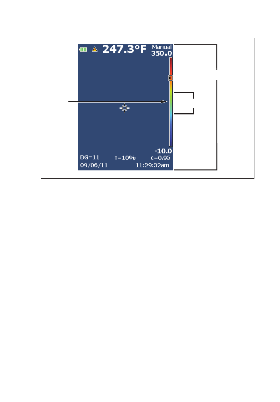
Level for Manual Operation Mode
When put into manual ranging, the level setting moves the thermal span up or
down within the total temperature range. See Figure 4. In the live manual
mode, the arrow buttons are always available to adjust the level and span.
To set the level:
1. Push to move the range to a higher temperature level.
2. Push to move the range to a lower temperature level.
While you adjust the manual level, the scale along the right side of the display
shows the thermal span as it moves to different levels within the total range.
1.888.610.7664 sales@GlobalTestSupply.com
Fluke-Direct.com
Performance Series Thermal Imagers
Menus
25
gju02.eps
Figure 4. Level and Span Settings
Temperature Span for Manual Operation Mode
When in manual mode, the span setting contracts or expands in a selected
palette in a temperature range within the total range. See Figure 4. In the live
manual mode, the arrow buttons are always available to adjust the level and
span.
To adjust the temperature span:
1. Push to increase or widen the temperature span.
2. Push to decrease or narrow the temperature span.
While you adjust the manual span, the scale along the right side of the display
shows the thermal span increasing or decreasing in size.
Total Imager Range
Span
Level
1.888.610.7664 sales@GlobalTestSupply.com
Fluke-Direct.com

Ti90, Ti95, Ti100, Ti105, Ti110, Ti125, TiR105, TiR110, TiR125
Users Manual
26
Emissivity Adjustment
The correct emissivity values are important for you to make the most accurate
temperature measurements. Emissivity of a surface can have a large effect on
the apparent temperatures that the Imager observes. Understanding the
emissivity of the surface being inspected can, but may not always, allow you to
obtain more accurate temperature measurements.
If you set a value that is <0.60, shows on the Imager display with this
caution:
Caution:
Emissivity <0.6
(see Manual)
Note
Surfaces with an emissivity of <0.60 make reliable and consistent
determination of actual temperatures problematic. The lower the
emissivity, the more potential error is associated with the Imager's
temperature measurement calculations. This is also true even when
adjustments to the emissivity and reflected background adjustments
are performed properly.
Emissivity is set directly as a value or from a list of emissivity values for some
common materials.
Note
If the Display is set to Display All, you see the information about
current emissivity as ε = x.xx.
Adjust by Number
To set the emissivity value:
1. Push .
2. Push / to highlight Measurement.
3. Push or to view the menu.
4. Push / to highlight Emissivity.
1.888.610.7664 sales@GlobalTestSupply.com
Fluke-Direct.com

Performance Series Thermal Imagers
Menus
27
5. Push or to view the menu.
6. Push / to highlight Adjust Number.
7. Push or to view the menu.
8. Push / to change the value.
9. Push:
• to set the change and go back to the live view.
• or to set the change and go back to the previous menu.
• to cancel the change and go back to the live view.
Select by Table
To select from a list of common materials:
1. Push .
2. Push / to highlight Measurement.
3. Push or to view the menu.
4. Push / to highlight Emissivity.
5. Push or to view the menu.
6. Push / to highlight Select Table.
7. Push or to view the emissivity table.
8. Push / to change the value.
9. Push:
• to set the change and go back to the live view.
• or to set the change and go back to the previous menu.
• to cancel the change and go back to the live view.
1.888.610.7664 sales@GlobalTestSupply.com
Fluke-Direct.com

Ti90, Ti95, Ti100, Ti105, Ti110, Ti125, TiR105, TiR110, TiR125
Users Manual
28
Reflected Background Temperature Compensation
Compensation for reflected background temperature is set in the Background
tab. Very hot objects or very cold objects can affect the apparent temperature
and measurement accuracy of the target or object of interest, especially when
surface emissivity is low. Adjustment of the reflected background temperature
can make the temperature measurement better in many situations. For more
information, see Emissivity Adjustment.
To adjust the background temperature:
1. Push .
2. Push / to highlight Measurement.
3. Push or to view the menu.
4. Push / to highlight Background.
5. Push or to view the menu.
6. Push / to change the value.
7. Push:
• to set the change and go back to the live view.
• or to set the change and go back to the previous menu.
• to cancel the change and go back to the live view.
Note
If the Display is set to Display All, you see the information about
current reflected background temperature as BG = xx.x.
1.888.610.7664 sales@GlobalTestSupply.com
Fluke-Direct.com

Performance Series Thermal Imagers
Menus
29
TiR-Mode
TiR-Mode (thermal sensitivity) expresses the ability of an infrared camera to
display a very good image even if the thermal contrast in a scene is low. A
camera with good sensitivity can distinguish objects in a scene that have very
little temperature difference between them.
Sensitivity is most often measured by a parameter called Noise Equivalent
Temperature Difference or NETD. NETD is defined as the amount of infrared
radiation required to produce an output signal equal to the system’s noise. The
noise rating of the system should be as low as possible.
To adjust the TiR-Mode:
1. Push .
2. Push / to highlight Image.
3. Push or to view the menu.
4. Push / to highlight TiR-Mode.
5. Push or to view the menu.
6. Push / to change the value.
7. Push:
• to set the change and go back to the live view.
• or to set the change and go back to the previous menu.
• to cancel the change and go back to the live view.
When TiR-Mode is turned on, images are enhanced with the improvement to
the image clarity of live scan targets. This mode is used for building envelope
applications such as roofing, restoration, and remediation. Response times in
this mode increase (slower refresh rate) and the maximum temperature range
is lower.
Note
When you scan with the TiR-Mode on, the Imager displays a slight
blurring effect. For best image results, hold the camera steady. Image
enhancement cannot be applied to images after they are taken.
1.888.610.7664 sales@GlobalTestSupply.com
Fluke-Direct.com

Ti90, Ti95, Ti100, Ti105, Ti110, Ti125, TiR105, TiR110, TiR125
Users Manual
30
Transmission/Transmittance Adjustment
When you do infrared inspections through infrared-transparent windows
(IR windows), not all of the infrared energy emitted from the objects of interest
is transmitted through the optical material in the window. If the transmission
percentage of the window is known, you can adjust this percentage in the
Imager or in the SmartView
software. Adjustment of the transmission
correction can make the accuracy of the temperature measurement better in
many situations.
To adjust the transmission percentage:
1. Push .
2. Push / to highlight Measurement.
3. Push or to view the menu.
4. Push / to highlight Transmission.
5. Push or to view the menu.
6. Push / to adjust the percentage.
7. Push:
• to set the change and go back to the live view.
• or to set the change and go back to the previous menu.
• to cancel the change and go back to the live view.
Note
If Display Information is set to Display All, you see the information
about current transmission correction as
τ = xx.
1.888.610.7664 sales@GlobalTestSupply.com
Fluke-Direct.com

Performance Series Thermal Imagers
Menus
31
Spot Temperatures
The Spot Temperatures are floating HI and LO temperature indicators that
move on the display as the temperature measurements of the image fluctuate.
To turn on/off the hot and cold spot indicators:
1. Push .
2. Push / to highlight Measurement.
3. Push or to view the menu.
4. Push / to highlight Spot Temp.
5. Push or to view the menu.
6. Push / to toggle this function ON or OFF.
7. Push:
• to set the change and go back to the live view.
• or to set the change and go back to the previous menu.
• to cancel the change and go back to the live view.
Note
If the Display is set to Display All, you see the information about
current transmission correction as τ = xxx%.
1.888.610.7664 sales@GlobalTestSupply.com
Fluke-Direct.com

Ti90, Ti95, Ti100, Ti105, Ti110, Ti125, TiR105, TiR110, TiR125
Users Manual
32
User-Definable Spot Markers
Up to three adjustable, fixed-temperature spot markers are available on the
display. You can use these markers to highlight a region before you save the
image. The marker selection is set as All Off, One Marker, Two Markers, or
Three Markers.
To set a Marker:
1. Push .
2. Push / to highlight Measurement.
3. Push or to view the menu.
4. Push / to highlight Markers.
5. Push or to view the menu.
6. Push the / to highlight the function between All OFF, One
Marker, Two Markers, and Three Markers.
7. Push or to set the marker option and go to the “Move Marker”
display. You will see the Move Marker icon and the labels on the function
buttons change to Done, Next, and Cancel.
To change the Marker position on the display:
1. Push to move the Marker location on the image.
2. Push to highlight the next marker. Do Step 1 again.
3. Do Step 2 for a third marker.
4. Push when done.
1.888.610.7664 sales@GlobalTestSupply.com
Fluke-Direct.com

Performance Series Thermal Imagers
Menus
33
Center Box
The Center Box feature is an adjustable temperature measurement zone (box)
that you can center on the infrared image. On some models, this zone (box)
expands and contracts to different levels in the infrared image. The zone lets
the user see an approximate maximum (MAX), average (AVG), and minimum
(MIN) temperature measurement in that area.
Note
When the Center Box feature is on, the Hot and Cold Spot
Temperature markers do not function. The user-definable spot
markers only function within the selected Center Box area. The level
and span of the Imager is also adjusted to the thermal scene within
the Center Box.
To enable or disable the Center Box feature:
1. Push .
2. Push / to highlight Measurement.
3. Push or to view the menu.
4. Push / to highlight Center Box.
5. Push or to view the menu.
6. Push / to toggle the function ON or OFF.
To set the size of the Center Box when enabled:
1. Push / to highlight Set Size.
2. Push or to view the display.
3. Push to increase the size of the Center Box.
4. Push to reduce the size of the Center Box.
5. When satisfied with the size of the Center Box, push:
• or to set the change and go back to the previous menu.
• to cancel the change and go back to the live view.
1.888.610.7664 sales@GlobalTestSupply.com
Fluke-Direct.com

Ti90, Ti95, Ti100, Ti105, Ti110, Ti125, TiR105, TiR110, TiR125
Users Manual
34
Image Menu
The Image menu has controls for different features used in the presentation of
the infrared image on the Imager's LCD and some saved image and video files.
Note
Data saved as .is2 or .is3 formats can easily be modified within
SmartView software. Still images saved in .bmp or .jpg format, as well
as video saved in .avi format will retain image settings at the time of
capture and save.
Palette
The Palette menu lets you change the false-color presentation of the infrared
images on display or captured. A variety of palettes are available, depending on
the model. Some palettes are more suitable for specific applications and can be
set as required. Two palette presentation modes are available. The Standard
Palettes offer an equal, linear presentation of colors that allow for best
presentation of detail. The Ultra Contrast Palettes offer a weighted presentation
of colors. These palettes work best in situations with high thermal contrast for
extra color contrast between the high temperatures and low temperatures.
Table 7 lists the palettes that are available for each model.
1.888.610.7664 sales@GlobalTestSupply.com
Fluke-Direct.com

Performance Series Thermal Imagers
Menus
35
Table 7. Palettes
Ti90
Ti95
Ti100
Ti105
Ti110
Ti125
TiR105
TiR110
TiR125
Standard Palettes
Grayscale • • • • • • • • •
Grayscale Inverted • • • • • •
Blue-Red • • • • • • • • •
High Contrast • • • • • • •
Hot Metal • • • • • • •
Ironbow • • • • • • • • •
Amber • • • • • • • •
Amber Inverted • • • • • •
Ultra Contrast™ Palettes
Grayscale • • • •
Grayscale Inverted • •
Blue-Red • • • •
High Contrast • •
Hot Metal • •
Ironbow • • • •
Amber • •
Amber Inverted • •
To set a palette:
1. Push .
2. Push / to highlight Measurement.
3. Push or to view the menu.
4. Push / to highlight Image.
1.888.610.7664 sales@GlobalTestSupply.com
Fluke-Direct.com

Ti90, Ti95, Ti100, Ti105, Ti110, Ti125, TiR105, TiR110, TiR125
Users Manual
36
5. Push or to view the menu.
6. Push / to highlight Palette.
7. Push or to view the menu.
8. Push / to highlight Standard or Ultra Contrast.
9. Push / to select a palette.
10. Push:
• to set the change and go back to the live view.
• or to set the change and go back to the previous menu.
• to cancel the change and go back to the live view.
IR-Fusion
®
IR-Fusion
®
makes it easier to understand infrared images through the use of an
aligned visible image and infrared image. The Imager automatically captures a
visible image with every infrared image to show you exactly what you see and
then allows you to more effectively show it to others.
IR-Fusion has different modes that vary by model, see Table 8. Full Visible
mode is also available. (The Fluke Ti100 does not have IR-Fusion and can only
display a full infrared image.)
Table 8. Infrared and IR-Fusion Modes by Model
Ti90
Ti95
Ti100
Ti105
Ti110
Ti125
TiR105
TiR110
TiR125
Full AutoBlend (min IR mode)
• • • •
Full AutoBlend (mid IR mode)
• • • • • •
Max IR (Full Thermal)
• • • • • • • • •
Full Visible
• • • • • • • •
Picture-in-Picture AutoBlend (min)
• • • •
Picture-in-Picture AutoBlend (mid)
• • • • • •
Picture-in-Picture AutoBlend (max)
• • • • • • •
Note: Ti105 and TiR105 models have aligned IR-Fusion from 1.2 m to 4.6 m (4 ft to 15 ft).
1.888.610.7664 sales@GlobalTestSupply.com
Fluke-Direct.com

Performance Series Thermal Imagers
Menus
37
To set the IR-Fusion mode:
1. Push .
2. Push / to highlight Measurement.
3. Push or to view the menu.
4. Push / to highlight Image.
5. Push or to view the menu.
6. Push / to highlight IR-Fusion.
7. Push or to view the menu.
8. Push / to highlight an option.
9. Push:
• to set the change and go back to the live view.
• or to set the change and go back to the previous menu.
• to cancel the change and go back to the live view.
Color Alarm (Temperature Alarm)
Certain models have various apparent temperature color alarms. The high-
temperature color alarm shows a full visible image and only shows infrared
information on objects or areas that are above the set apparent temperature
alarm level. The low-temperature/dew point color alarm shows a full visible
image and only shows infrared information on objects or areas that are below
the set apparent temperature/dew point color alarm level. The user must
manually find and set these parameters. Certain models also display color
isotherms, or infrared information, inside or outside of a set of both high and
low limits.
1.888.610.7664 sales@GlobalTestSupply.com
Fluke-Direct.com

Ti90, Ti95, Ti100, Ti105, Ti110, Ti125, TiR105, TiR110, TiR125
Users Manual
38
Note
The Imager does not sense ambient or surface dew point level
automatically. To use the low-temperature color alarm function as a
dew point color alarm, manual determination and input of surface dew
point temperature will yield the best results. Depending on the
situation, the colors presented will, or will not, actually show areas with
possible dew point condensation.
To view the Color Alarm menu:
1. Push .
2. Push / to highlight Image.
3. Push or to view the menu.
4. Push / to highlight Color Alarm.
5. Push or to view the menu.
Set High-Temperature Color Alarm
To set a high-temperature color alarm:
1. From the Color Alarm menu, push / to highlight the option: Set
High Alarm.
2. Push to open the Color Alarm menu.
3. Push / to adjust the temperature setting.
4. Push:
• to set the change and go back to the live view.
• or to set change and go back to the previous menu.
• to cancel the change and go back to the live view
1.888.610.7664 sales@GlobalTestSupply.com
Fluke-Direct.com

Performance Series Thermal Imagers
Menus
39
Set Low-Temperature/Dew Point Color Alarm
To set a low-temperature/dew point color alarm:
1. From the Color Alarm menu, push / to highlight Set Low
Alarm.
2. Push to open the Color Alarm menu.
3. Push / to adjust the temperature setting.
4. Push:
• to set the change and go back to the live view.
• or to set the change and go back to the previous menu.
• to cancel the change and go back to the live view.
Outside/Inside Alarm
If you set values for the high-temperature color alarm and a low-temperature
color alarm, the Imager will have the options for inside or outside isotherm color
alarms.
To set an outside/inside isotherm color alarm:
1. From the Color Alarm menu, push / to highlight Outside or
Inside.
2. Push:
• to set the change and go back to the live view.
• or to set the change and go back to the previous menu.
• to cancel the change and go back to the live view.
1.888.610.7664 sales@GlobalTestSupply.com
Fluke-Direct.com

Ti90, Ti95, Ti100, Ti105, Ti110, Ti125, TiR105, TiR110, TiR125
Users Manual
40
Display Graphics Presentation
The options for how you view the on-screen graphics are in the Display menu.
These options are Display All, Details and Scale, Scale Only, and Image Only.
To set the display:
1. Push .
2. Push / to highlight Measurement.
3. Push or to view the menu.
4. Push / to highlight Image.
5. Push or to view the menu.
6. Push / to highlight Display.
7. Push or to view the menu.
8. Push / to highlight an option.
9. Push:
• to set the change and go back to the live view.
• or to set the change and go back to the previous menu.
• to cancel the change and go back to the live view.
1.888.610.7664 sales@GlobalTestSupply.com
Fluke-Direct.com

Performance Series Thermal Imagers
Menus
41
Camera Menu
The Camera menu has controls and options for secondary camera features
such as Compass, Video, Laser Pointer, Torch, and Backlight level.
Compass
The Imager includes an eight-point cardinal compass on the display. The
compass has on and off functions. This compass lets you accurately record the
direction the camera is pointing for analysis and reports.
To set the compass:
1. Push .
2. Push / to highlight Camera.
3. Push or to view the menu.
4. Push / to highlight Compass.
5. Push or to view the menu.
6. Push / to highlight ON or OFF.
7. Push to set the option.
8. Push:
• to go back to the live view.
• or to go back to the previous menu.
• to cancel the change and go back to the live view.
Note
shows on the display when the compass cannot make a reading.
1.888.610.7664 sales@GlobalTestSupply.com
Fluke-Direct.com

Ti90, Ti95, Ti100, Ti105, Ti110, Ti125, TiR105, TiR110, TiR125
Users Manual
42
Video
The Ti110, Ti125, TiR110, TiR125 have .avi (with mpeg encoding) video
capture for a maximum of five minutes. The controls include stop, rewind, fast
forward, and pause/play functions.
Ti125 and TiR125 have radiometric video. With radiometric (.is3) video, the
thermal scene and complexity of the recorded data affects the amount of time
(2.5 minutes to 5 minutes) available for video recording. The controls include
stop, rewind, fast forward, and pause/play functions.
Streaming video output (Ti125, TiR125 only) is available with the USB
connection to a PC with SmartView software.
The Video selection toggles between Video Off, Video/Audio, and Video Only.
The video capture format is set in the Settings menu. For more information, see
page 50.
To set:
1. Push .
2. Push / to highlight Camera.
3. Push or to view the menu.
4. Push / to highlight Video.
5. Push or to view the menu.
6. Push / to highlight an option.
7. Push to set the option.
8. Push:
• to set the change and go back to the live view.
• or to set the change and go back to the previous menu.
• to cancel the change and go back to the live view.
1.888.610.7664 sales@GlobalTestSupply.com
Fluke-Direct.com

Performance Series Thermal Imagers
Menus
43
Video Recording
To record:
1. Pull the primary trigger to start recording. The r icon shows in the upper
left corner or the display and the recording time graphic at the bottom of
the display shows the remaining time.
2. Pull the primary trigger to pause recording. The p icon shows in the
upper left corner or the display.
3. Push to end the recording session.
4. Push to save the video file. The Imager displays the VIDEO menu
as a prompt to disable the feature or continue in the same mode.
Video Playback
To playback:
1. Push .
2. Push / to highlight Memory.
3. Push to view the thumbnails of saved files.
4. Push to highlight a file for playback. All .avi files show
the k icon in the upper right corner of the thumbnail.
5. Push to set a file for playback.
6. Push to start the playback. The i icon shows in the upper left
corner of the display if an audio file is attached to the video file.
7. During playback, push or for fast forward and rewind. Push
to continue normal playback.
8. Push to exit the playback mode.
1.888.610.7664 sales@GlobalTestSupply.com
Fluke-Direct.com

Ti90, Ti95, Ti100, Ti105, Ti110, Ti125, TiR105, TiR110, TiR125
Users Manual
44
Laser Pointer
The laser pointer is a sighting aid and is offset from the infrared camera. As a
result, it may not always represent the exact center of the infrared or visible
image.
The laser dot does not appear on an infrared-only image, but does on visible-
only or AutoBlend images. The laser dot cannot be seen in the visible channel
of the IR-Fusion image if obscured by the center point marker graphic.
The laser pointer selections are Trigger Laser, Trigger Torch, and Laser/Torch.
When set, pull the secondary trigger to turn on, release the secondary trigger to
turn off.
Warning
To prevent eye damage and personal injury, do not look into the
laser. Do not point laser directly at persons or animals or
indirectly off reflective surfaces.
To set:
1. Push .
2. Push / to highlight Camera.
3. Push or to view the menu.
4. Push / to highlight Laser/Torch.
5. Push or to view the menu.
6. Push / to highlight an option.
7. Push to set the option.
8. Push:
• to set the change and go back to the live view.
• or to set the change and go back to the previous menu.
• to cancel the change and go back to the live view.
The laser warning symbol () shows in the Header zone of the display when
the laser is turned on and you pull the secondary trigger.
1.888.610.7664 sales@GlobalTestSupply.com
Fluke-Direct.com

Performance Series Thermal Imagers
Menus
45
LED Light (Torch)
The LED light illuminates darker work areas. When set, pull the secondary
trigger to operate.
Note
When the LED light is on and an image is captured, the LED light
momentarily shines brighter and functions as a visible camera flash.
To set:
1. Push .
2. Push / to highlight Camera.
3. Push or to view the menu.
4. Push / to highlight Laser/Torch.
5. Push or to view the menu.
6. Push / to highlight an option.
7. Push to set the option.
8. Push:
• to set the change and go back to the live view.
• or to set the change and go back to the previous menu.
• to cancel the change and go back to the live view.
Backlight
The backlight level control is set to low, medium, and high. To set the backlight:
1. Push .
2. Push / to highlight Camera.
3. Push or to view the menu.
4. Push / to highlight Backlight.
5. Push or to view the menu.
6. Push / to highlight an option.
7. Push:
• to set the change and go back to the live view.
• or to set the change and go back to the previous menu.
• to cancel the change and go back to the live view.
1.888.610.7664 sales@GlobalTestSupply.com
Fluke-Direct.com

Ti90, Ti95, Ti100, Ti105, Ti110, Ti125, TiR105, TiR110, TiR125
Users Manual
46
Fluke Connect™ Wireless System
The Imager supports the Fluke Connect™ Wireless System (may not be
available in all regions). Fluke Connect™ is a system that wirelessly connects
your Fluke test tools with an app on your smartphone. It enables you to see
images from your infrared camera on your smartphone screen, save images to
the asset's EquipmentLog™ history in the Fluke Cloud™, and share images
with your team.
The Fluke Connect app works with the iPhone and Android Phone. The app is
available for download from the Apple App Store and Google App Marketplace.
How to access Fluke Connect:
1. Insert the Fluke Connect Wireless SD Card into the Imager.
3. Power on the Imager.
4. On your smartphone, go to Settings > Wi-Fi.
5. Select the Wi-Fi network that begins with "Fluke..".
6. Go to the Fluke Connect App and select "Thermal Imager" from the list.
You are now able to take images on the Imager.
4. Pull the trigger on the Imager to capture the image. The image is now in
the buffer and you can save or edit.
5. Push to save the image and view the image on the phone app.
Go to www.flukeconnect.com for more information about how to use the app.
1.888.610.7664 sales@GlobalTestSupply.com
Fluke-Direct.com

Performance Series Thermal Imagers
Menus
47
CNX™ Wireless System
The Imager supports the Fluke CNX™ Wireless System (may not be available
in all regions). It can discover up to 10 3000 Series wireless tools up to 20
meters away. From those 10, you can select 5 tools to view their live
measurements on the Imager display.
To discover a supported tool:
1. If not already on, turn on each wireless tool and make sure the wireless
feature is enabled. See the documentation of each tool for more
information about how to use.
2. Turn on the Imager.
3. Push .
4. Push / to highlight Camera.
5. Push or to view the menu.
6. Push / to highlight CNX.
7. Push or to view the menu.
8. Push / to highlight ON.
9. Push or start the discovery process.
When done, the Imager presents a list with the ID and name of available
tools found within the 20 m distance.
10. Push / to highlight a tool name.
11. Push to select the tool.
12. Repeat steps 10 and 11 for each tool to show on the display.
13. Push when done.
The labels change to include an Edit function. By default, the Imager
shows and saves the data for the selected tools. If these settings are
acceptable, push to exit the CNX setup menu.
1.888.610.7664 sales@GlobalTestSupply.com
Fluke-Direct.com

Ti90, Ti95, Ti100, Ti105, Ti110, Ti125, TiR105, TiR110, TiR125
Users Manual
48
To edit the selection:
14. Push / to highlight the tool name.
15. Push or to view the Edit menu. The Edit menu gives you a
choice to display the measurement data and/or save it to the SD memory
card.
16. Push to accept the change.
17. Push when done to exit the menu.
The display updates to show the wireless icon and live measurement for
each selected wireless tool.
Memory Menu
The Memory Menu allows the user to review captured images and videos, as
well as audio annotations and IR-PhotoNotes in a thumbnail view format.
Review Data Files
To view stored images on the SD memory card:
1. Push .
2. Push / to highlight Memory.
3. Push or to view the memory menu.
4. Push to highlight the thumbnail of the file for review.
5. Push to review the file.
1.888.610.7664 sales@GlobalTestSupply.com
Fluke-Direct.com

Performance Series Thermal Imagers
Menus
49
Delete Data Files
To erase one image from the SD memory card:
1. Push .
2. Push / to highlight Memory.
3. Push or to view the memory menu.
4. Push to highlight the thumbnail of the file to delete.
5. Highlight Selected Image and push . The Imager prompts you to
continue or cancel.
6. Push to delete the file.
To erase all the images from the SD memory card:
1. Push .
2. Push / to highlight Memory.
3. Push .
4. Highlight All Image and push . The Imager prompts you to continue or
cancel.
5. Push to delete all files on the SD memory card.
1.888.610.7664 sales@GlobalTestSupply.com
Fluke-Direct.com

Ti90, Ti95, Ti100, Ti105, Ti110, Ti125, TiR105, TiR110, TiR125
Users Manual
50
Settings Menu
The Settings menu has adjustments for user preferences such as units of
temperature measurement, file format of stored data, auto off settings, date,
time, and language. This menu also has a section that displays information
about the Imager such as model number, serial number, and firmware versions.
Units
To change the temperature units:
1. Push .
2. Push / to highlight Settings.
3. Push or to view the menu.
4. Push / to highlight Units.
5. Push or to view the menu.
6. Push / to highlight an option.
7. Push:
• to set the change and go back to the live view.
• or to set the change and go back to the previous menu.
• to cancel the change and go back to the live view.
File Format
Data can be saved to the SD memory card in different file formats. Image
format selections are .bmp, .jpg, and .is2. Video format selections are .avi and
.is3. These selections remain valid when you turn the Imager off or on.
To change the file format:
1. Push .
2. Push / to highlight Settings.
1.888.610.7664 sales@GlobalTestSupply.com
Fluke-Direct.com

Performance Series Thermal Imagers
Menus
51
3. Push or to view the menu.
4. Push / to highlight File Format.
5. Push or to view the menu.
6. Push / to highlight an option.
7. Push to set the option.
8. Push:
• to set the change and go back to the live view.
• or to set the change and go back to the previous menu.
• to cancel the change and go back to the live view.
Images saved in the .is2 file format have the consolidation of all data into a
single file and are more flexible for analysis and modification in the included
SmartView software. This file format consolidates the infrared image,
radiometric temperature data, visible image, voice annotation, and
IR-PhotoNotes into one location.
For situations where a smaller file size with maximum resolution is needed and
modification is not, choose the .bmp file format. For the smallest file size where
modification is not needed and image quality and resolution are not as
important, choose the .jpg file format.
The .bmp and .jpg files can be emailed and then opened on most PC and MAC
systems without special software. These formats do not allow full analysis
capabilities or modification.
The .is2 file format can be emailed and then opened with SmartView Software.
This format has the maximum versatility. Visit the Fluke website or contact
Fluke to find out how to download SmartView analysis and reporting software at
no charge.
1.888.610.7664 sales@GlobalTestSupply.com
Fluke-Direct.com

Ti90, Ti95, Ti100, Ti105, Ti110, Ti125, TiR105, TiR110, TiR125
Users Manual
52
Auto Off
Auto Off is set as off or on. When set to on, the Imager goes into the Sleep
mode after 5 minutes of inactivity. After 20 minutes of inactivity the Imager turns
off.
Note
When the battery is connected to AC Power, or the unit is in video
mode, the Sleep Mode/Auto Off feature is automatically disabled.
To set or disable the Auto Off feature:
1. Push .
2. Push / to highlight Settings.
3. Push or to view the menu.
4. Push / to highlight Auto Off.
5. Push or to view the menu.
6. Push / to highlight an option.
7. Push to set the option.
8. Push:
• to go back to the live view.
• or to set the change and go back to the previous menu.
• to cancel the change and go back to the live view.
When the Auto off feature is disabled and the Imager is left on, the Imager
stays on until the battery is depleted.
1.888.610.7664 sales@GlobalTestSupply.com
Fluke-Direct.com

Performance Series Thermal Imagers
Menus
53
Date
The date can be displayed in one of two formats: MM/DD/YY or DD/MM/YY.
To set the date:
1. Push .
2. Push / to highlight Settings.
3. Push or to view the menu.
4. Push / to highlight Date.
5. Push / to highlight date format.
6. Push or to view the menu.
7. Push to set the date format.
8. Push or to change the setting.
9. Push to move to the next setting.
10. Push or to change the setting.
11. Push to move to the next setting.
12. Push or to change the setting.
13. Push:
• to set the change and go back to the live view.
• or to set the change and go back to the previous menu.
• to cancel the change and go back to the live view.
1.888.610.7664 sales@GlobalTestSupply.com
Fluke-Direct.com

Ti90, Ti95, Ti100, Ti105, Ti110, Ti125, TiR105, TiR110, TiR125
Users Manual
54
Time
To set the time:
1. Push .
2. Push / to highlight Settings.
3. Push or to view the menu.
4. Push / to highlight Time.
5. Push or to view the menu.
Time displays in two different formats: 24 hour or 12 hour. To set the time
format:
1. Push / to highlight time format.
2. Push or to view the menu.
3. Push or to change the setting.
4. Push to move to the next setting.
5. Push or to change the setting.
The 12 hour format has a selection for setting whether the time is AM or PM. To
set AM or PM:
6. Push:
• to set the change and go back to the live view.
• or to set the change and go back to the previous menu.
• to cancel the change and go back to the live view.
1.888.610.7664 sales@GlobalTestSupply.com
Fluke-Direct.com

Performance Series Thermal Imagers
Menus
55
Language
To change the display to a different language:
1. Push .
2. Push / to highlight Settings.
3. Push or to view the menu.
4. Push / to highlight Language.
5. Push or to view the menu.
6. Push or to change the setting.
7. Push to set a new language.
8. Push:
• to set the change and go back to the live view.
• or to set the change and go back to the previous menu.
• to cancel the change and go back to the live view.
Imager Information
You can access information about the Imager from the Settings Menu. This
includes:
• Model
• Camera serial number
• Refresh rate
• Engine serial number
• Firmware version
• FPGA #
• Factory calibration date
• Production date
1.888.610.7664 sales@GlobalTestSupply.com
Fluke-Direct.com

Ti90, Ti95, Ti100, Ti105, Ti110, Ti125, TiR105, TiR110, TiR125
Users Manual
56
To display the Imager Info:
1. Push .
2. Push / to highlight Settings.
3. Push or to view the menu.
4. Push / to highlight Imager Info.
5. Push or to view the menu.
6. Push / to scroll through the menu.
7. Push:
• to set the change and go back to the live view.
• or to set the change and go back to the previous menu.
• to cancel the change and go back to the live view.
Maintenance
The Imager does not require maintenance.
Warning
To prevent eye damage and personal injury, do not open the
Product. The laser beam is dangerous to eyes. Have the Product
repaired only through an approved technical site.
How to Clean the Case
Clean the case with a damp cloth and a weak soap solution. Do not use
abrasives, isopropyl alcohol, or solvents to clean the case or lens/window.
1.888.610.7664 sales@GlobalTestSupply.com
Fluke-Direct.com

Performance Series Thermal Imagers
Maintenance
57
Battery Care
Warning
To prevent personal injury and for safe operation of the Product:
• Do not put battery cells and battery packs near heat or fire.
Do not put in sunlight.
• Do not disassemble or crush battery cells and battery packs.
• Remove batteries to prevent battery leakage and damage to
the Product if it is not used for an extended period.
• Connect the battery charger to the mains power outlet before
the charger.
• Use only Fluke approved power adapters to charge the
battery.
• Keep cells and battery packs clean and dry. Clean dirty
connectors with a dry, clean cloth.
Caution
To prevent damage:
• Do not expose Product to heat sources or high-temperature
environments such as an unattended vehicle in the sun.
• Do not store the Imager on the charger for more than 24
hours as reduced battery life may result.
• Charge the Imager for a two-hour minimum at six-month
intervals for maximum battery life. Without use, the battery
will self-discharge in approximately six months. Batteries
stored for long periods will need two to ten charging cycles
for full capacity.
• Always operate in the specified temperature range.
Caution
Do not incinerate the Product and/or battery. Go to Fluke’s
website for recycling information.
1.888.610.7664 sales@GlobalTestSupply.com
Fluke-Direct.com

Ti90, Ti95, Ti100, Ti105, Ti110, Ti125, TiR105, TiR110, TiR125
Users Manual
58
General Specifications
Temperature
Operating ............................................................ -10 °C to +50 °C (14 °F to 122 °F)
Storage ................................................................ -20 °C to +50 °C (-4 °F to +122 °F)
without batteries
Charging .............................................................. 0 °C to 40 °C (32 °F to 104 °F)
Relative Humidity .................................................. 10 to 95 % non-condensing
Altitude
Operating ............................................................. 2,000 m
Storage ................................................................ 12,000 m
Display .................................................................... Color LCD, 3.5″ diagonal (Portrait
orientation) with Backlight (selectable
high, medium, low)
Software ................................................................. SmartView
®
full analysis and reporting
software available for free download at
www.fluke.com.
Power
Battery ................................................................. Lithium-ion rechargeable smart battery
pack with 5-segment LED display to
show charge level. Lithium-ion battery
pack meets the requirements of UN
Tests and Criteria Manual, Part III,
Subparagraph 38.3.
Battery Life .......................................................... 4+ hours continuous use for each
battery pack (assumes 50 %
brightness of LCD)
Battery Charge Time ........................................... 2.5 hours to full charge
Battery Charging ................................................. Ti SBC3 Two Bay Battery Charger
rated: 10-15 Vdc 2 A or charge battery
pack in Imager with included ac
adapter rated: 100-240 Vac 50/60 Hz,
15 V 2 A. Optional 12 V Automotive
charging adapter.
Battery Charging Temperature ............................ 0 °C to 40 °C
AC Operation ...................................................... AC operation with included power
supply: 110 – 240 Vac, 50/60 Hz 15 V
2 A
Power Saving ...................................................... Sleep Mode activated after 5 minutes
of inactivity
Automatic Power Off after 20 minutes
of inactivity
1.888.610.7664 sales@GlobalTestSupply.com
Fluke-Direct.com

Performance Series Thermal Imagers
General Specifications
59
Safety Standards
CAN/CSA, UL ..................................................... C22.2 No. 61010-1, UL STD 61010-1
EU ....................................................................... EN61010-1, pollution degree 2,
CAT none
Electromagnetic Compatibility (EMI, EMC)
US ....................................................................... FCC Part 15 Subpart B
EN61326-1 .......................................................... Electromagnetic Environment
Controlled
Korea (KCC) ....................................................... Class A Equipment (Industrial
Broadcasting & Communication
Equipment)
This product meets requirements for
industrial (Class A) electromagnetic
wave equipment and the seller or user
should take notice of it. This
equipment is intended for use in
business environments and not to be
used in homes.
Radio Standards
US ....................................................................... 47 CFR 15.207, 15.209, 15.249,
FCCID: T68-F125
Canada ............................................................... RSS210, IC: 6627A-F125
EU ....................................................................... EN300.328, EN301.489
Vibration ................................................................ 2 G, IEC 68-2-26
Shock ..................................................................... 25 G, IEC 68-2-29
Laser Pointer ......................................................... IEC 60825-1:2007 Class II, FDA LFR
1040.10 Class II, JQA JIS C 6802
Drop ....................................................................... 2 meter
Size (H x W x L) ..................................................... 28.4 x 8.6 x 13.5 cm
(11.2 x 3.4 x 5.3 in)
Weight .................................................................... 72.6 kg (1.6 lb)
Enclosure Rating .................................................. IP54
Warranty ................................................................ 2 years
Calibration Cycle .................................................. 2 years (assumes normal operation
and normal aging)
Supported Languages .......................................... Czech, Dutch, English, Finnish, French,
German, Hungarian, Italian, Japanese,
Korean, Polish, Portuguese, Russian,
Simplified Chinese, Spanish, Swedish,
Traditional Chinese, and Turkish
1.888.610.7664 sales@GlobalTestSupply.com
Fluke-Direct.com

Ti90, Ti95, Ti100, Ti105, Ti110, Ti125, TiR105, TiR110, TiR125
Users Manual
60
Detailed Specifications
Temperature Measurements
Temperature Range (not calibrated below -10 °C)
Ti90, Ti95, Ti100, Ti105, Ti110 ....................... -20 °C to +250 °C
Ti125 ............................................................... -20 °C to +350 °C
TiR105, TiR110, TiR125 .................................. -20 °C to +150 °C
Accuracy .............................................................. ±2 °C or 2 % (whichever is greater) at
25 °C ambient
Measurement Modes ........................................... Smooth Auto-Scaling and Manual
Scaling
On-screen Emissivity Correction ......................... all models
Imaging Performance
Field of View
Ti100, Ti105, Ti110, Ti125, TiR110, TiR125 ... 31 ° x 22.5 °
Ti95 ................................................................. 26 ° x 26 °
Ti90 ................................................................. 19.5 ° x 26 °
Spatial Resolution
Ti100, Ti105, Ti110, Ti125, TiR110,
TiR125 (IFOV) ................................................. 3.39 mRad
Ti90, Ti95 (IFOV) ............................................. 5.6 mRad
Minimum Focus Distance
Ti100, Ti105, TiR105 ....................................... 122 cm (approx. 48 in)
Ti90, Ti95 ........................................................ 46 cm (approx. 18 in)
Ti110, Ti125, TiR110, TiR125 ......................... 15 cm (approx. 6 in)
Focus
Ti90, Ti95, Ti100, Ti105, TiR105 ..................... Focus-free
Ti110, Ti125, TiR110, TiR125 ......................... IR-OptiFlex™ focus
Image Capture or Refresh Rate
Ti90, Ti95, Ti100, TiR105, TiR110, TiR125 ..... 9 Hz
Ti105, Ti110, Ti125 ......................................... 9 Hz or 30 Hz (factory set)
Detector Type (Focal Plane Array, uncooled microbolometer)
Ti100, Ti105, Ti110, Ti125, TiR110, TiR125 ... 160 X 120
Ti95 ................................................................. 80 x 80
Ti90 ................................................................. 80 x 60
Thermal Sensitivity (NETD)
Ti90 ................................................................. 150 mK
Ti95, Ti100, Ti105, Ti110, Ti125 ..................... ≤100 mK (0.1 °C at 30 °C target
temperature)
TiR105, TiR110, TiR125 ..................................
≤80 mK (0.08 °C at 30 °C target
temperature)
1.888.610.7664 sales@GlobalTestSupply.com
Fluke-Direct.com

Performance Series Thermal Imagers
Detailed Specifications
61
Image Presentation
Standard Palettes
Ti90 ................................................................. Ironbow, Blue-Red, Grayscale
Ti95 ................................................................. Blue-red, Grayscale, High-Contrast,
Hot Metal, Ironbow, Amber
Ti100 ............................................................... Ironbow, Blue-Red, Grayscale, Amber
Ti105, Ti110, Ti125, TiR105, TiR110,
TiR125 ............................................................ Blue-Red, Grayscale, Inverted
Grayscale, High Contrast, Amber,
Inverted Amber, Hot Metal, Ironbow
Ultra Contrast™ Palettes
Ti110, TiR110 ................................................. Ironbow, Blue-Red, Grayscale
Ti125, TiR125 ................................................. Blue-Red, Grayscale, Inverted
Grayscale, High Contrast, Amber,
Inverted Amber, Hot Metal, Ironbow
Level and Span
Smooth Auto-Scaling and Manual scaling of level and span
Minimum Span (in manual mode)
Ti90, Ti95, Ti100, Ti105, Ti110, Ti125 ....... 2.5 °C
TiR105, TiR110, TiR125 ............................. 2.0 °C
Minimum span (in auto mode)
Ti90, Ti95, Ti100, Ti105, Ti110, Ti125 ....... 5 °C
TiR105, TiR110, TiR125 ............................. 2.5 °C
IR-Fusion
®
Information
Max IR (Full Thermal) ..................................... Ti90, Ti95, Ti100, Ti105, Ti110, Ti125,
TiR105, TiR110, TiR125
AutoBlend™
min mode .................................................... Ti110, Ti125, TiR110, TiR125
mid mode .................................................... Ti105, Ti110, Ti125, TiR105, TiR110,
TiR125
Picture-in-Picture
min mode .................................................... Ti110, Ti125, TiR110, TiR125
mid mode .................................................... Ti105, Ti110, Ti125, TiR105, TiR110,
TiR125
max mode ................................................... Ti95, Ti105, Ti110, Ti125, TiR105,
TiR110, TiR125
Full Visible ...................................................... Ti90, Ti95, Ti105, Ti110, Ti125,
TiR105, TiR110, TiR125
1.888.610.7664 sales@GlobalTestSupply.com
Fluke-Direct.com

Ti90, Ti95, Ti100, Ti105, Ti110, Ti125, TiR105, TiR110, TiR125
Users Manual
62
Voice Annotation ................................................... Ti110, Ti125, TiR110, TiR125
Video Recording
Standard Video Recording .................................. Ti110, Ti125, TiR110, TiR125
Radiometric Video Recording .............................. Ti125, TiR125
Streaming Video (Remote Display) ...................... Ti125, TiR125
Image and Data Storage
Image Capture, Review, Save Mechanism ......... One-handed image capture, review,
and save capability
Storage Medium .................................................. SD Memory Card (included memory
card will store at least 1200 fully
radiometric (.is2) IR and linked visual
images each with 60 seconds voice
annotations or 3000 basic (.bmp or
.jpg) images, transferable to PC
through included multiformat USB
card reader or USB cable
Note
The addition of IR-PhotoNotes, standard video, or radiometric video may vary
the total number of images that can be stored on the SD memory card.
File Formats ........................................................ Non-Radiometric (.avi, .bmp, .jpg) or
Fully-Radiometric (.is2, .is3)
No analysis software required for Non-
Radiometric (.avi, .bmp, .jpg) files
Export File Formats with
SmartView
®
Software .......................................... JPEG, JPG, JPE, JFIF, BMP, GIF,
DIB, PNG, TIF, TIFF
Memory Review ................................................... Thumbnail view navigation and review
selection
1.888.610.7664 sales@GlobalTestSupply.com
Fluke-Direct.com