
TiS55+/TiS75+
Thermal Imager
Users Manual
É
October 2020 (English)
© 2020 Fluke Corporation. All rights reserved.
Specifications are subject to change without notice.
All product names are trademarks of their respective companies.
1.888.610.7664 sales@GlobalTestSupply.com
Fluke-Direct.com

LIMITED WARRANTY AND LIMITATION OF LIABILITY
Each Fluke product is warranted to be free from defects in material and workmanship under normal use and
service. The warranty period is two years and begins on the date of shipment. Parts, product repairs, and
services are warranted for 90 days. This warranty extends only to the original buyer or end-user customer of a
Fluke authorized reseller, and does not apply to fuses, disposable batteries, or to any product which, in Fluke's
opinion, has been misused, altered, neglected, contaminated, or damaged by accident or abnormal conditions of
operation or handling. Fluke warrants that software will operate substantially in accordance with its functional
specifications for 90 days and that it has been properly recorded on non-defective media. Fluke does not
warrant that software will be error free or operate without interruption.
Fluke authorized resellers shall extend this warranty on new and unused products to end-user customers only
but have no authority to extend a greater or different warranty on behalf of Fluke. Warranty support is available
only if product is purchased through a Fluke authorized sales outlet or Buyer has paid the applicable
international price. Fluke reserves the right to invoice Buyer for importation costs of repair/replacement parts
when product purchased in one country is submitted for repair in another country.
Fluke's warranty obligation is limited, at Fluke's option, to refund of the purchase price, free of charge repair, or
replacement of a defective product which is returned to a Fluke authorized service center within the warranty
period.
To obtain warranty service, contact your nearest Fluke authorized service center to obtain return authorization
information, then send the product to that service center, with a description of the difficulty, postage and
insurance prepaid (FOB Destination). Fluke assumes no risk for damage in transit. Following warranty repair, the
product will be returned to Buyer, transportation prepaid (FOB Destination). If Fluke determines that failure was
caused by neglect, misuse, contamination, alteration, accident, or abnormal condition of operation or handling,
including overvoltage failures caused by use outside the product’s specified rating, or normal wear and tear of
mechanical components, Fluke will provide an estimate of repair costs and obtain authorization before
commencing the work. Following repair, the product will be returned to the Buyer transportation prepaid and the
Buyer will be billed for the repair and return transportation charges (FOB Shipping Point).
THIS WARRANTY IS BUYER'S SOLE AND EXCLUSIVE REMEDY AND IS IN LIEU OF ALL OTHER
WARRANTIES, EXPRESS OR IMPLIED, INCLUDING BUT NOT LIMITED TO ANY IMPLIED WARRANTY OF
MERCHANTABILITY OR FITNESS FOR A PARTICULAR PURPOSE. FLUKE SHALL NOT BE LIABLE FOR
ANY SPECIAL, INDIRECT, INCIDENTAL OR CONSEQUENTIAL DAMAGES OR LOSSES, INCLUDING LOSS
OF DATA, ARISING FROM ANY CAUSE OR THEORY.
Since some countries or states do not allow limitation of the term of an implied warranty, or exclusion or limitation
of incidental or consequential damages, the limitations and exclusions of this warranty may not apply to every
buyer. If any provision of this Warranty is held invalid or unenforceable by a court or other decision-maker of
competent jurisdiction, such holding will not affect the validity or enforceability of any other provision.
11/99
1.888.610.7664 sales@GlobalTestSupply.com
Fluke-Direct.com

i
Table of Contents
Title Page
Introduction.......................................................................................................... 1
Contact Fluke Corporation................................................................................... 1
Safety Information ............................................................................................... 2
Product Familiarization ........................................................................................ 2
Features ....................................................................................................... 2
The Product .................................................................................................. 3
Primary and Secondary Triggers.................................................................. 4
Control Panel................................................................................................ 5
Touch Screen (Display) ................................................................................ 6
Menu Controls .............................................................................................. 6
Basic Operation ................................................................................................... 8
Turn On and Off the Product ........................................................................ 8
Focus............................................................................................................ 8
Laser Pointer ................................................................................................ 9
Capture Image.............................................................................................. 9
Save Image .................................................................................................. 10
Save Images to PC....................................................................................... 10
Main Menu........................................................................................................... 11
Measurement Menu............................................................................................. 12
Level/Span.................................................................................................... 13
Emissivity Adjustment................................................................................... 14
Transmissivity............................................................................................... 15
Image Menu......................................................................................................... 15
IR-Fusion
TM
Technology ............................................................................... 16
Palette Menu ....................................................................................................... 17
Select a Palette ............................................................................................ 18
Display Menu....................................................................................................... 19
Marker .......................................................................................................... 19
Delta-T.......................................................................................................... 20
Spot Box ....................................................................................................... 20
Fluke Connect Menu ........................................................................................... 21
Asset Identification (Asset ID) ...................................................................... 22
Assign Asset ID Tag with a QR Code or Barcode................................. 22
Assign Asset ID Tag Manually............................................................... 22
Exit an Asset ID Tag.............................................................................. 22
1.888.610.7664 sales@GlobalTestSupply.com
Fluke-Direct.com

ii
TiS55+/TiS75+
Users Manual
Assign a Different Asset ID Tag ............................................................. 23
Fluke Connect Tools ..................................................................................... 23
Connection Icons........................................................................................... 24
Save Images to Fluke Connect Cloud........................................................... 25
Sign in to Fluke Connect WiFi Network.................................................. 25
Sign out of Fluke Connect WiFi Network................................................ 26
Sign in to Fluke Connect Cloud.............................................................. 26
Sign out of Fluke Connect Cloud............................................................ 26
Fluke Connect Wireless System.................................................................... 27
Pair Hotspot to Fluke Connect ............................................................... 27
Pair to Mobile App .................................................................................. 27
Save Images to Shared Folder...................................................................... 28
Sign in to Shared Folder WiFi Network .................................................. 28
Sign out of Shared Folder WiFi Network ................................................ 29
Sign in to Shared Folder......................................................................... 29
Sign out of Shared Folder ...................................................................... 30
Settings Menu....................................................................................................... 31
Capture Settings............................................................................................ 33
Video ...................................................................................................... 33
Record Video.......................................................................................... 33
View Video ............................................................................................. 34
Auto Capture .......................................................................................... 34
Bluetooth Headset.................................................................................. 35
Date............................................................................................................... 35
Time .............................................................................................................. 36
Image Annotation ................................................................................................. 36
Text Notes ..................................................................................................... 36
Notes with Single Image......................................................................... 36
Add a Note to Multiple Images ............................................................... 37
Audio Notes................................................................................................... 37
Record Audio Notes ............................................................................... 37
Review Audio Notes ............................................................................... 38
IR-PhotoNotes............................................................................................... 38
Make IR-PhotoNotes .............................................................................. 39
Review IR-PhotoNotes ........................................................................... 39
Flag an Image ............................................................................................... 39
Manage Images.................................................................................................... 40
Delete an Image ............................................................................................ 40
Delete Multiple Images.................................................................................. 40
Delete All Images .......................................................................................... 40
Memory Menu (Memory Gallery).......................................................................... 41
View Image.................................................................................................... 42
Asset ID......................................................................................................... 42
Fluke Connect Desktop Software......................................................................... 42
Download Fluke Connect Software ............................................................... 43
Update Firmware........................................................................................... 43
Accessories .......................................................................................................... 43
Maintenance ......................................................................................................... 44
Clean the Case.............................................................................................. 44
1.888.610.7664 sales@GlobalTestSupply.com
Fluke-Direct.com

Thermal Imager
Table of Contents
iii
Lens Care ..................................................................................................... 44
Battery Care ................................................................................................. 44
Charge Batteries........................................................................................... 45
Two-Bay Battery Charger Base............................................................. 45
AC Power Socket on Imager ................................................................. 45
Optional 12 V Vehicle Charger.............................................................. 46
Radio Frequency Data......................................................................................... 46
Specifications ...................................................................................................... 46
1.888.610.7664 sales@GlobalTestSupply.com
Fluke-Direct.com

1
Introduction
The Fluke TiS55+/TiS75+ Thermal Imagers (the Product or Imager) are handheld, infrared
imaging cameras for use in many applications. These applications include equipment
troubleshooting, preventive and predictive maintenance, building diagnostics, and research
and development.
The Imager displays thermal images on a high-visibility, industrial-quality LCD touch screen.
The Imager can save images to internal memory or to a removable memory card. Saved
images and data stored in internal memory or on the memory card can be transferred to a
PC through a direct USB connection to the PC or by wireless transfer to a PC or mobile
device.
The Imager works with the Fluke Connect app available on mobile devices and with the
Fluke Connect software available for PCs.
A rugged, rechargeable lithium-ion smart battery provides power to the Imager. Direct ac
power is accessible with the included ac power adapter.
1.888.610.7664 sales@GlobalTestSupply.com
Fluke-Direct.com

TiS55+/TiS75+
Users Manual
2
Safety Information
General Safety Information is in the printed Safety Information document that ships with the
A Warning identifies hazardous conditions and procedures that are dangerous to the user.
A Caution identifies conditions and procedures that can cause damage to the Product or the
equipment under test.
Product Familiarization
The manual explains features for multiple models. Because models have different features,
not all of the information in the manual may apply to your Imager. Use Tab le 1 to identify the
features of your Imager.
Features
Table 1 is a list of the features of the Imager.
Table 1. Features
Feature TiS55+ TiS75+
Focus/Image Enhancement
Advanced manual focus
EdgeSharp Technology
IR-Fusion Technology
Full screen IR Autoblend (Preset percentage selection)
Visible Light Camera
Picture-in-Picture (PIP)
Image annotations
IR-PhotoNotes
Audio (Voice)
Tex t
Video mode
Auto capture mode
Markers
35
Spot Boxes
35
Dew point setting
Color Alarms
1.888.610.7664 sales@GlobalTestSupply.com
Fluke-Direct.com
Thermal Imager
Product Familiarization
3
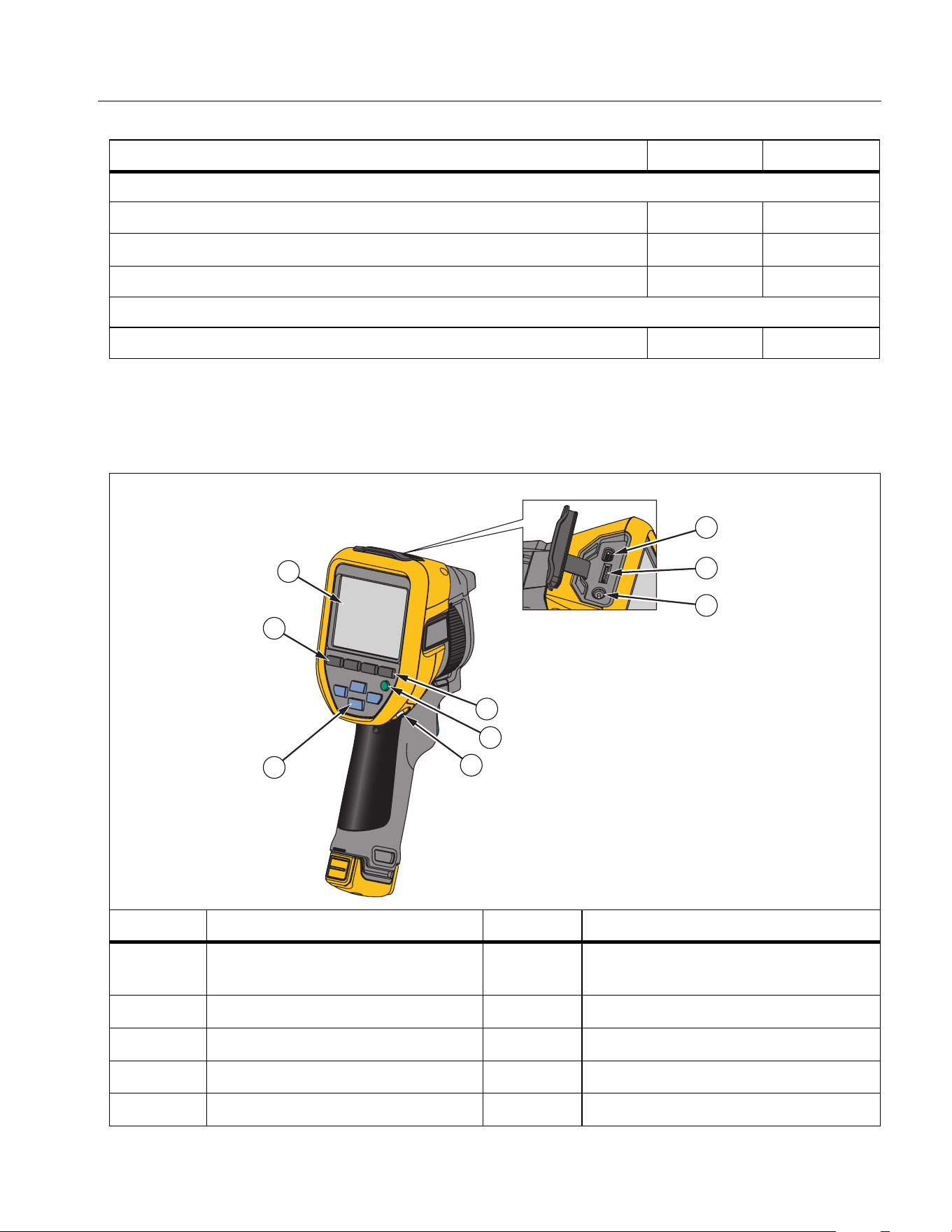
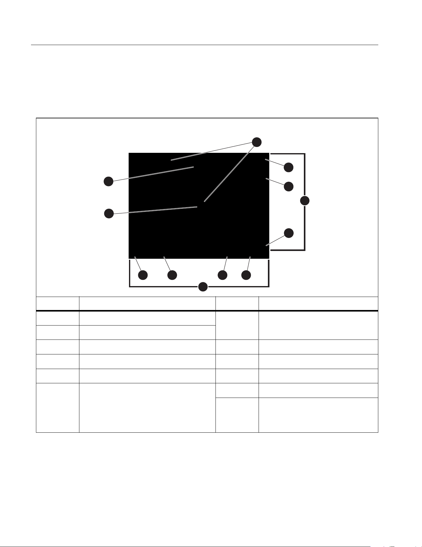
The Product
Table 2 shows the front of the Product.
Wireless connectivity
WiFi
Bluetooth
Fluke Connect Connect to Fluke tools
Fluke Connect/desktop software
Stream video (radiometric streaming)
Table 2. Front
Item Description Item Description
Control Panel Navigation
buttons
F
Handstrap anchor
See Control Panel.
G
USB Cable
Touch screen
H
Memory Card slot
D
Memory button
I
Power input
E
Power button
Table 1. Features (cont.)
Feature TiS55+ TiS75+
7
8
9
4
5
6
1
2
3
1.888.610.7664 sales@GlobalTestSupply.com
Fluke-Direct.com
TiS55+/TiS75+
Users Manual
4
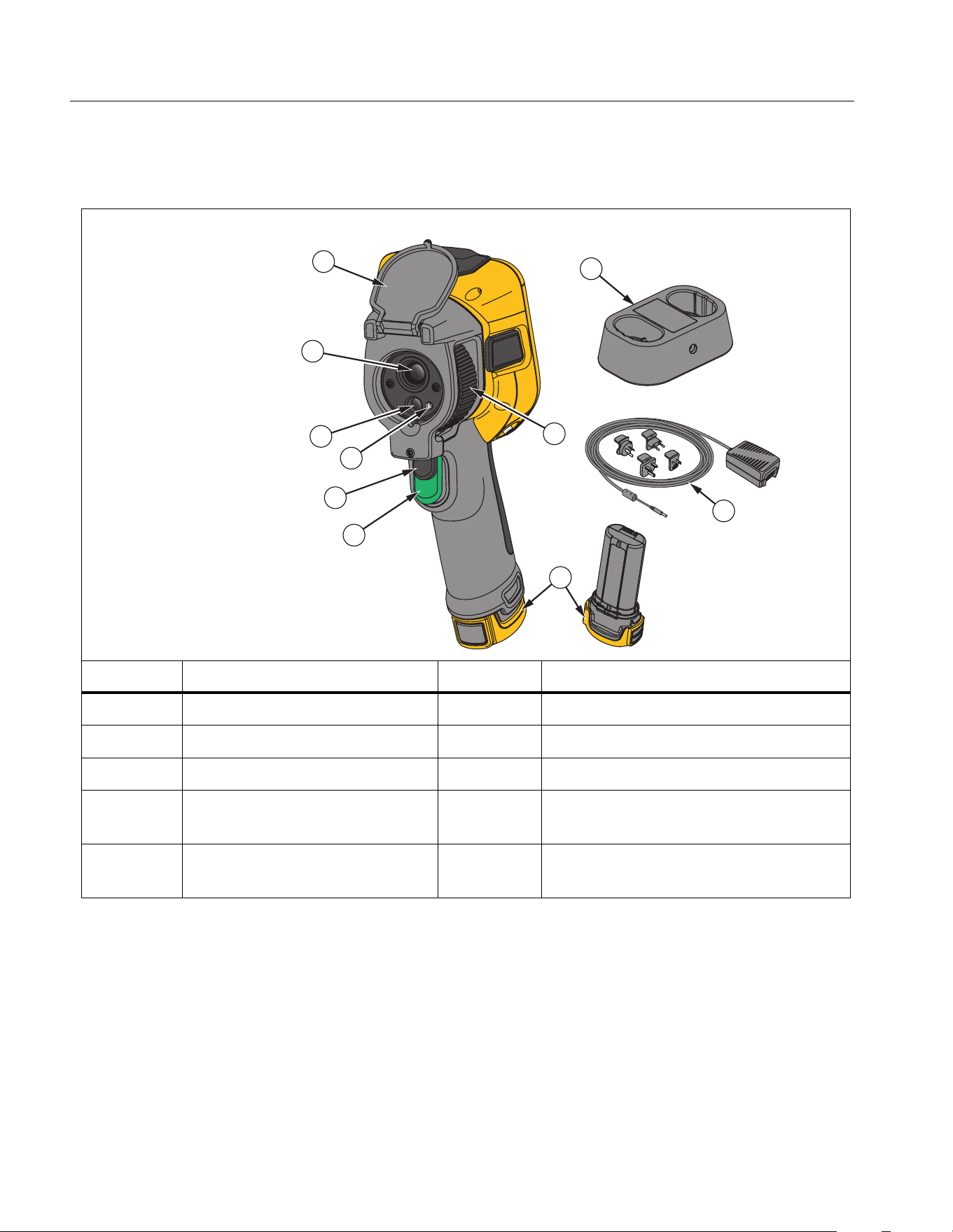
Table 3 shows the back of the Product.
Primary and Secondary Triggers
The two-part trigger is located in the standard trigger position for a pistol-grip device. The
larger, green trigger is the primary trigger. The smaller, black trigger is the secondary trigger.
Use the primary trigger to capture an image to save or edit. The default function of the
secondary trigger is the laser pointer. From any menu, use the secondary trigger to return to
camera mode. You can assign a specific function to the secondary trigger, see Settings
Menu.
Table 3. Back
Item Description Item Description
J
Retractable Lens Cover
O
Primary Trigger
K
Infrared Camera Lens
P
Manual Focus Control
L
Visual Light Camera Lens
Q
Lithium-ion Smart Battery
M
Laser Pointer
R
AC Power Supply with Mains
Adapters
N
Secondary Trigger
S
2-Bay Battery Charge Base
(TiS75+only)
10
11
12
13
14
15
19
18
17
16
1.888.610.7664 sales@GlobalTestSupply.com
Fluke-Direct.com

Thermal Imager
Product Familiarization
5
Control Panel
The control panel is used to change parameters or select functions and options. Ta ble 4 lists
the functions of the buttons on the Control Panel.
Table 4. Control Panel
Button Description
O
Push to turn on or turn off the Product.
s
Push to open the main menu.
Within a submenu:
Push to either save the change and go back to the previous menu.
Or
Push to perform the function listed on the submenu key.
d
Push to open the main menu.
Within a submenu:
Push to either cancel the change and go back to the previous menu.
Push to perform the function listed on the submenu key.
Or
Push and hold for 2 seconds to exit out of all menus.
a
Push and hold for 2 seconds to toggle between Manual/Auto Level
and Span.
With Level/Span set to Manual, push to rescale the temperature
values on the display at that time. See Level/Span.
m
Push to review, edit, and delete captured images. See Memory
Menu (Memory Gallery).
W
Y Z
X
Push to move the cursor and highlight an option.
With Level/Span set to Manual, push to adjust the Level and Span.
See Level/Span.
With Level/Span set to Auto, push to adjust the IR-Fusion level.
In the Spot Box menu, push to adjust the size or position of the spot
box. See Spot Box.
In the Marker menu, push to move the marker. See Marker.
1.888.610.7664 sales@GlobalTestSupply.com
Fluke-Direct.com
TiS55+/TiS75+
Users Manual
6
Touch Screen (Display)
The touch screen is the primary user interface of the Product. The touch screen has a
backlight for work in dimly lit spaces.
Table 5 shows the default information on the screen of the Product.
Menu Controls
To use the menus to change and view settings:
1. Tap the display to open the main menu.
2. Tap an icon on the main menu to open a sub-menu. See Ta bl e 7.
Table 5. Display
Item Description Item Description
Center point marker
G
Temperature range lower
value
Center point temperature
High and low temperature markers
H
Status bar
D
Scale
I
Background temperature
E
Temperature range upper value
J
Emissivity value
F
Range bar
The range of colors in the palette
mapped to a certain range of
temperatures
K
Date and time
L
Battery status
1
2
5
6
7
9101112
8
3
4
1.888.610.7664 sales@GlobalTestSupply.com
Fluke-Direct.com
Thermal Imager
Product Familiarization
7
The background of the selected icon changes to yellow.
3. Tap a menu control to set and change options. See Ta ble 6.
4. To close a sub-menu and return to live camera mode, tap the sub-menu icon again.
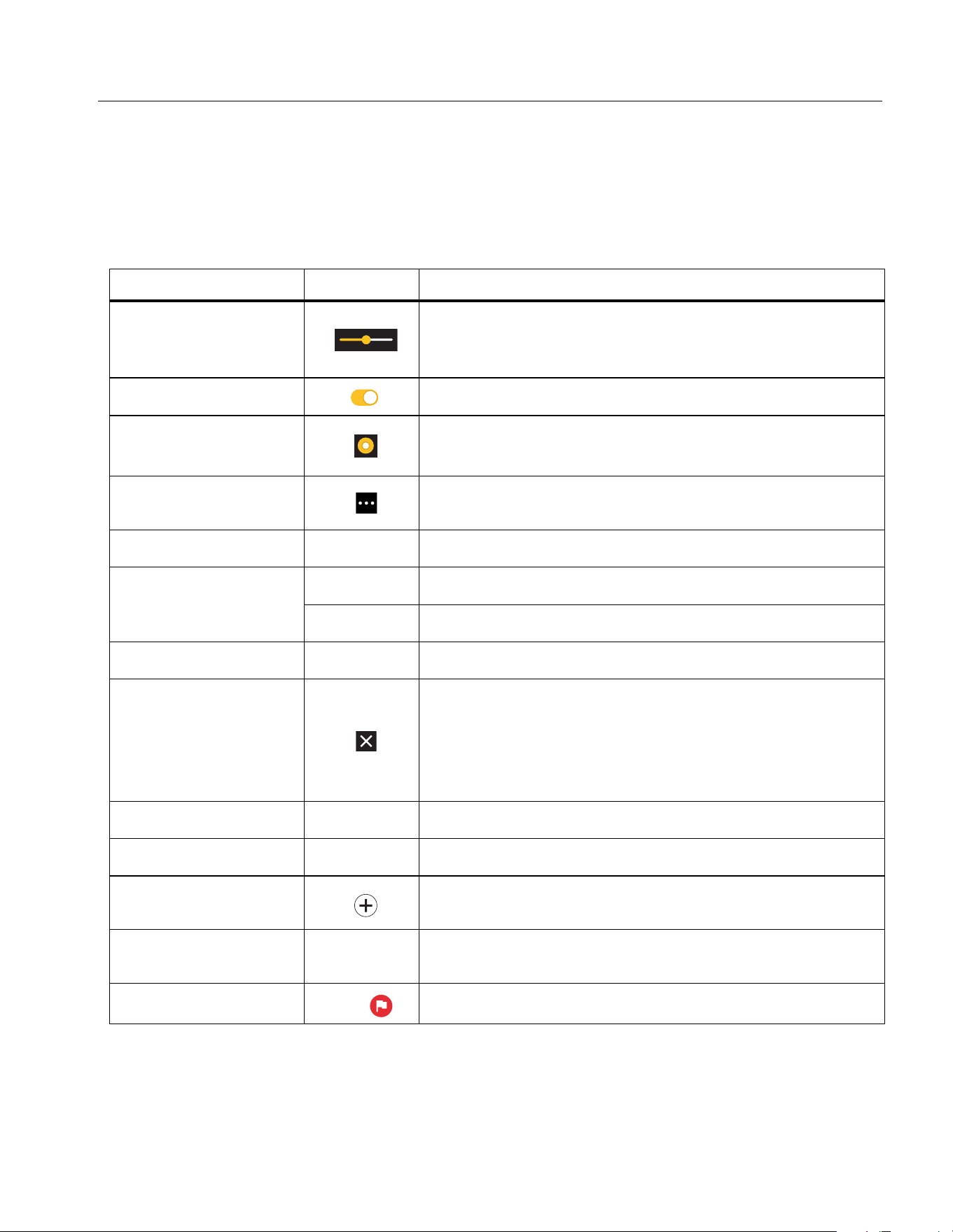
Table 6 is a list of the menu controls.
Table 6. Menu Controls
Item Control Function
Slider bar
Adjusts a value. Touch and slide the bar to the left to
decrease the value or to the right to increase the
value.
Toggle switch Turns on or off a feature.
Radio button Selects one item from a list.
More menu options
button
Opens a menu to show other menu options.
Option menu button
Y
Opens an option menu to adjust a setting.
Numerical value
adjuster buttons
9/K
Decreases a numerical value.
8/4
Increases a numerical value.
Back arrow
J
Returns to the previous menu.
Exit button
Closes menu and returns to camera mode.
Or,
Exits out of an Asset ID. See Asset Identification
(Asset ID).
Delete button
T
Delete an image. See Manage Images.
Note button
N
View, add, or edit a note. See Text Notes.
Add a note button
With at least one note attached to an image, add
another note to the image. See Text Notes.
Asset ID button
D
Add or remove an asset ID tag. See Asset
Identification (Asset ID).
Flag toggle switch
H/
Toggle to add or remove a flag. See Flag an Image.
1.888.610.7664 sales@GlobalTestSupply.com
Fluke-Direct.com
TiS55+/TiS75+
Users Manual
8
Basic Operation
Turn On and Off the Product
Before you use the Product for the first time, charge the battery. See Charge Batteries.
To turn on the Product, push and hold O for 1 second. To turn off the Product, push and
hold O for 2 seconds.
Note
All thermal Imagers need sufficient warm-up time for accurate temperature
measurements and best image quality. Warm-up time can vary by model and
environmental conditions. Although most Imagers are fully warmed up in 3 minutes
to 5 minutes, wait a minimum of 10 minutes if the most accurate temperature
measurement is important to your application. When you move an Imager between
environments with large differences in ambient temperature, allow for additional
adjustment time.
Focus
Correct focus makes sure that the infrared energy is correctly directed onto the pixels of the
detector. Without correct focus, the thermal image can be blurry and the radiometric data
may be inaccurate. Out-of-focus infrared images are frequently unusable or of little value.
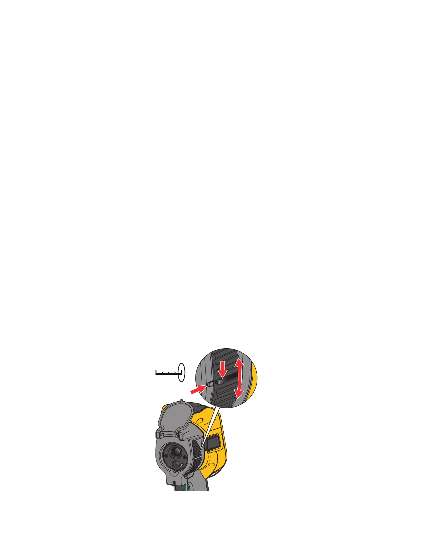
To focus with the advanced manual focus system, rotate the Manual Focus Control until the
inspection object is in proper focus.
To simulate fixed focus at 1.2 m, align the raised bar on the focus control with the marker on
the case. See Figure 1.
Figure 1. Fixed Focus
1.2 m
1.888.610.7664 sales@GlobalTestSupply.com
Fluke-Direct.com

Thermal Imager
Basic Operation
9
Laser Pointer
The Imager has a laser pointer. The laser pointer is a sighting aid and is offset from the
infrared camera. As a result, it may not always represent the exact center of the infrared or
visible image.
The laser dot does not appear on an infrared-only image, but does on visible-only or
AutoBlend images. The laser dot cannot be seen in the visible channel of the IR-Fusion
image if obscured by the center point marker graphic.
Pull the secondary trigger to turn on laser pointer, release the secondary trigger to turn off
the laser pointer.
Capture Image
In normal operation (video is off), use the primary (green) trigger to capture a thermal image.
The captured image goes into a memory buffer. You can view and annotate the image in the
memory buffer before you store the image.When video is on, the primary trigger is the start/
stop for video recording.
To capture an image:
1. Focus on a target.
2. Pull and release the Primary Trigger or double tap on the display to capture and freeze
the image.
The image is in the memory buffer for you to save or edit the image.
Depending on the selected file format settings, the Imager shows the captured image
and a menu bar. The menu bar shows the available options. You can add text or audio
notes, create an IR-PhotoNote, or flag the image. To edit an image, see Image
Annotation.
Note
Asset ID tags, flags, and notes can be saved with images captured in .is2 file format
only. To select .is2 file format, see Settings Menu.
3. To assign an asset ID tag to the image, tap Scan Asset ID, or tap Remove Asset ID to
remove an asset ID tag from the image. See Asset Identification (Asset ID).
4. Tap Save.
1.888.610.7664 sales@GlobalTestSupply.com
Fluke-Direct.com

TiS55+/TiS75+
Users Manual
10
Save Image
To save an image as a data file:
1. Capture an image.
The image is in the memory buffer for you to save or edit the image.
2. Push s to save the image as a file and go back to the live view. Alternatively, push
the primary (green) trigger to save the image and go back to the live view.
The image is stored in the location selected in Device Settings > Image Storage.
Save Images to PC
To save images to a PC with the USB cord:
1. Turn on the Product.
2. Connect one end of the USB cord into the USB port on the Product and the other end
into a USB port on a PC.
The PC recognizes the Product as an external memory storage device.
3. On the PC:
a. Browse to the directory on the Product.
b. Copy and paste or drag the images to a directory on the PC.
4. Remove the USB cord from the PC and the Product.
To save images to a PC from the memory card:
1. Remove the memory card from the Product, see Tab le 2.
2. Insert the memory card into the memory card port on a PC.
The PC recognizes the card as a storage device.
3. On the PC:
a. Browse to the directory on the memory card.
b. Copy and paste or drag the images to a directory on the PC.
4. When you are finished, return the memory card to the Product.
1.888.610.7664 sales@GlobalTestSupply.com
Fluke-Direct.com

Thermal Imager
Main Menu
11
Main Menu
Table 7 is a list of the secondary menus available in the Main Menu. From any menu, push
the green trigger button to return to Camera mode.
Table 7. Main Menu
Secondary Menu Function
g
Measurement
Set the infrared settings. See Measurement Menu.
a
Image
Adjust how the image appears. See Image Menu.
P
Palette
Set the palette to use on the image. See Palette Menu.
M
Display
Set the features to show on the display. See Display Menu.
F
Fluke Connect
Save images over a WiFi connection. See Fluke Connect
Menu.
Note
The Fluke Connect system is not available in all
countries.
S
Device Settings
Set user preferences and view information about the
Product. See Settings Menu.
1.888.610.7664 sales@GlobalTestSupply.com
Fluke-Direct.com

TiS55+/TiS75+
Users Manual
12
Measurement Menu
Table 8 is a list of the options available in the Measurement menu.
Table 8. Measurement Menu
Option Menu Option Description
Level/Span
Auto
Sets the Level/Span to adjust automatically or
manually.
Manual
Set Level/Span
With Level/Span set to Manual, changes the
Level/Span. See Level/Span.
Emissivity
Custom Value
Sets a custom emissivity value when a value
from the standard emissivity table is not
appropriate for the measurement. See
Emissivity Adjustment.
<options>
Select an emissivity value from a list of common
materials. Use the scroll bar to see all of the
options. See Emissivity Adjustment.
Background
<options>
Changes the background temperature to
compensate for reflected background
temperature.
Very hot objects or very cold objects can affect
the apparent temperature and measurement
accuracy of the target, especially when surface
emissivity is low. Adjust the reflected
background temperature to improve the
accuracy of the measurement.
Transmissivity
<options>
Changes the values used to calculate the
temperature based on the transmission
percentage of the infrared-transparent window
(IR window). See Transmissivity.
1.888.610.7664 sales@GlobalTestSupply.com
Fluke-Direct.com
Thermal Imager
Measurement Menu
13
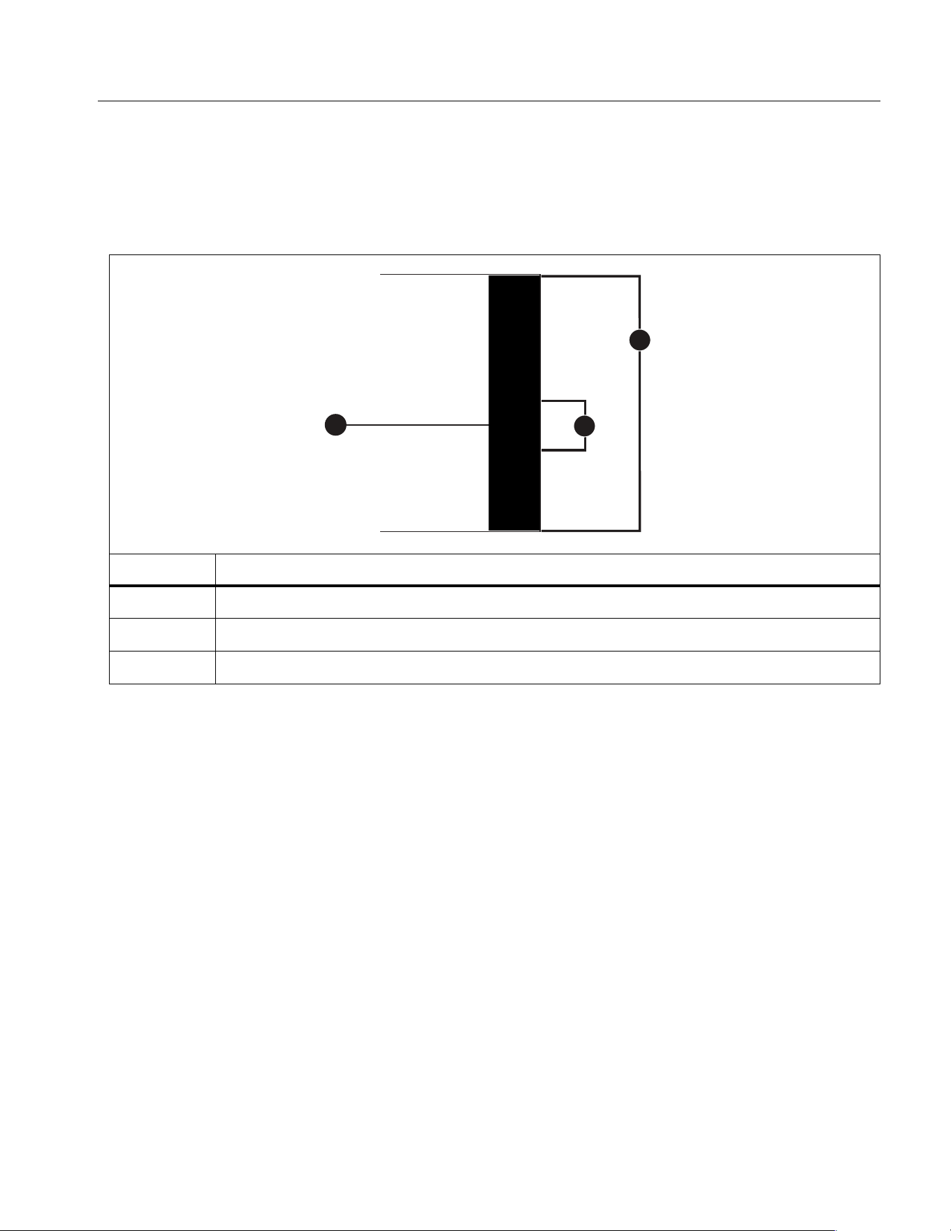
Level/Span
Level and Span are values within the total range of temperature. Level is the temperature
level to view within the total range of temperatures. Span is the span of temperatures to view
within the total range of temperatures. See Table 9.
With Level/Span set to Auto, the Imager sets Level/Span based on the total temperature
range.
With Level/Span set to Manual, the level setting moves the thermal span up or down within
the total temperature range.
To change Level/Span:
1. Select g > Level/Span > Manual, or push a for 2 seconds.
2. Select Set Level/Span.
3. Push:
•
Y
to decrease the temperature span.
•
Z
to increase the temperature span.
•
W
to move the span to a higher temperature level.
•
X
to move the span to a lower temperature level.
Table 9. Level and Span Settings
Item Description
Level
Span
Total range
1
2
3
1.888.610.7664 sales@GlobalTestSupply.com
Fluke-Direct.com

TiS55+/TiS75+
Users Manual
14
The scale along the right side of the display shows the thermal span increasing or
decreasing in size and shows the span as it moves to different levels within the total range.
See Table 9.
To use the temperature range high and low values on the display for future measurements:
1. Set Level/Span to Manual.
2. Push a to rescale the display and save the temperature values on the display at that
time.
To use a different temperature range, use the arrow keys to change the Level/Span, or
push a twice to rescale.
Note
The Imager always powers up in the same Level/Span mode, Auto or Manual, as
when the Imager was powered down.
Emissivity Adjustment
All objects radiate infrared energy. The actual surface temperature and emissivity of the
target affects the quantity of energy radiated. The Imager senses the infrared energy from
the surface of the target and uses the data to calculate an estimated temperature value.
Many common materials such as wood, water, skin, cloth, and painted surfaces, including
metal, radiate energy well and have a high emissivity factor of ≥90 % (or 0.90). The Imager
measures temperatures accurately on targets with a high emissivity.
Shiny surfaces or unpainted metals do not radiate energy well and have a low emissivity
factor of <0.60. For the Imager to calculate a more accurate estimate of the actual
temperature of targets with a low emissivity, adjust the emissivity setting.
W Warning
To prevent personal injury, see emissivity information for actual temperatures.
Reflective objects result in lower than actual temperature measurements.
These objects pose a burn hazard.
Set emissivity as a direct value or from a list of emissivity values for some common
materials. If the emissivity value is <0.60, a caution shows on the display.
Note
Surfaces with an emissivity of
<
0.60 make it difficult to determine reliable and
consistent actual temperatures. The lower the emissivity, the greater the potential of
error when the Imager calculates the temperature measurement because more of
the energy reaching the camera is specified as background temperature. This is also
true even when adjustments to the emissivity and reflected background adjustments
are performed properly.
1.888.610.7664 sales@GlobalTestSupply.com
Fluke-Direct.com

Thermal Imager
Image Menu
15
Transmissivity
When you do infrared inspections through IR windows, not all of the infrared energy emitted
from the target is transmitted through the optical material in the window. If you know the
transmission percentage of the window, adjust the transmission percentage in the Imager or
in Fluke Connect desktop software to improve the accuracy of the measurement.
When you do not do infrared inspections through an IR window, set Transmissivity to 100 %
to disable the correction percentage.
Image Menu
Table 10 is a list of the options available in the Image menu.
Table 10. Image Menu
Option Menu Option Description
IR-Fusion
0% to 100%
The Imager automatically captures a visible
image with every infrared image to show where
a potential problem might be. See IR-Fusion
TM
Technology
Picture in Picture On/Off
Shows the infrared image imposed on the
visible light image to improve the picture
context. Use with IR-Fusion to further improve
the image.
EdgeSharp
TM
On/Off
Use EdgeSharp to digitally enhance an image
with temperature overlays. EdgeSharp
increases the visibility of actual features in an
image.
1.888.610.7664 sales@GlobalTestSupply.com
Fluke-Direct.com
TiS55+/TiS75+
Users Manual
16
IR-Fusion
TM
Technology
IR-Fusion
TM
technology makes it easier to understand, analyze, and communicate infrared
images through the use of an aligned visible image and infrared image. The Imager
automatically captures a visible image with every infrared image to show you precisely
where a potential problem might be, and then allows you to more effectively communicate it
to others.
Note
The visible image and infrared image can be customized or separated in SmartView
and Fluke Connect Software when you use the .is2 or .is3 file format. See Settings
Menu.
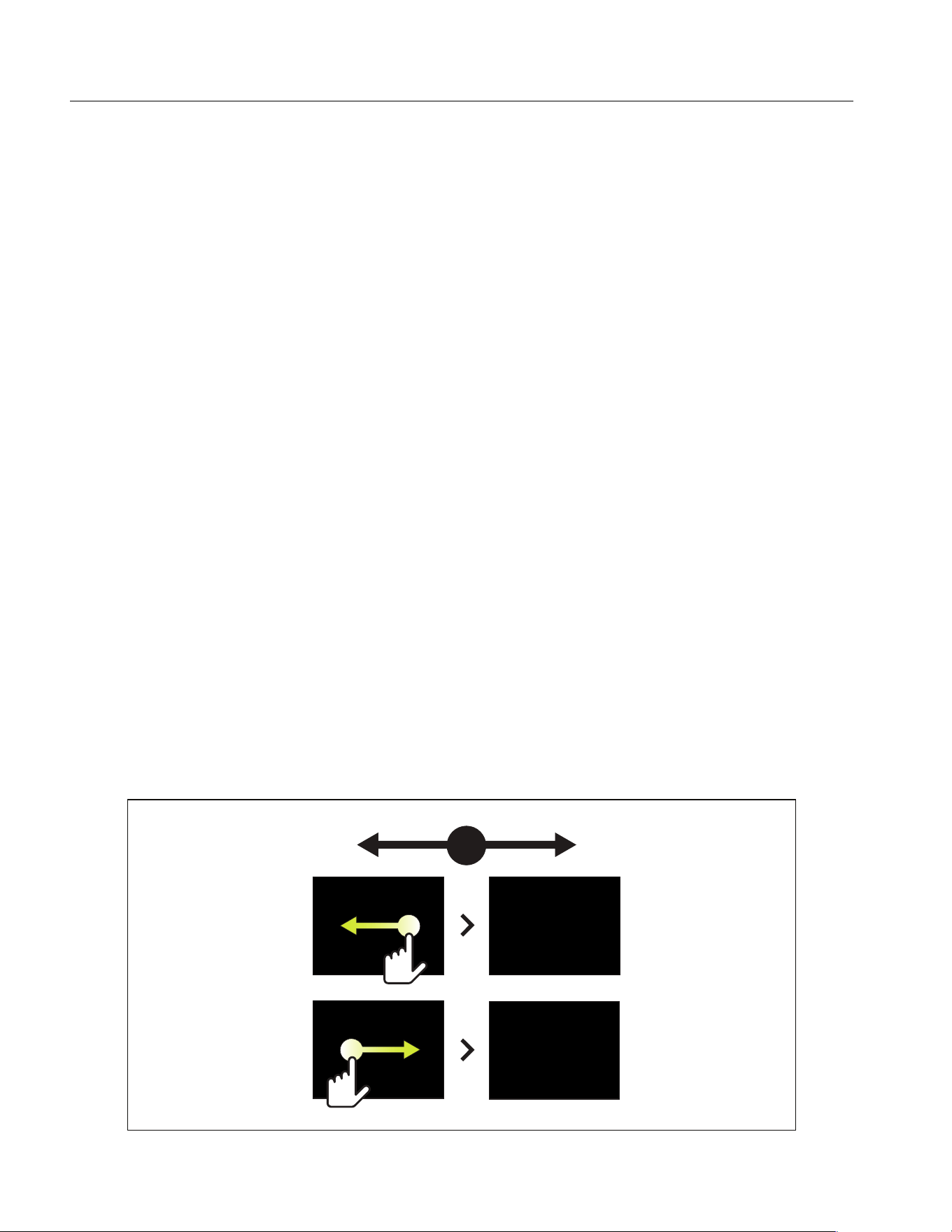
The IR-Fusion slider bar sets the Product to take images from full visible light mode to full
IR-Fusion mode. Use a blend between visible light mode and IR-Fusion to view an object
with some temperature overlays.
To adjust the IR-Fusion level:
1. Tap A.
2. Use the slider bar to set the IR-Fusion level.
Alternatively, you can adjust the IR-Fusion level in camera mode:
With Level/Span set to Auto, push Y or Z to change the IR-Fusion level.
Or,
Touch the display and slide left to right to increase the level of IR-Fusion. Slide from right
to left to decrease the IR-Fusion level. See Figure 2.
Figure 2. IR-Fusion Level
1.888.610.7664 sales@GlobalTestSupply.com
Fluke-Direct.com

Thermal Imager
Palette Menu
17
Palette Menu
Use the Palette menu to select the pallete and set color alarms. The standard palettes offer
an equal, linear presentation of colors that allow for best presentation of detail. Tab le 11 is a
list of the options in the Palette menu.
Table 11. Palette Menu
Option Menu Option Description
Palette
Grayscale
Ironbow
High
Contrast
Amber
Hot Metal
Blue-Red
Shows palette thumbnails. See Select a Palette.
Color Alarm
Off
Turn off color alarms
High Alarm
Turn on the high-temperature color alarm. The high-
temperature color alarm shows a full visible image and
only shows infrared information on objects or areas that
are above the set apparent temperature level. Use the
arrows to adjust the temperature threshold.
Low Alarm
Turn on the low-temperature color alarm. The low-
temperature color alarm shows a full visible image and
only shows infrared information on objects or areas that
are below the set apparent temperature level. Use the
arrows to adjust the temperature threshold.
Inside
Range
Turn on the inside range alarm. The inside range color
alarm shows a full visible image and only shows color
isotherms, or infrared information on objects or areas that
are within the high and low temperature settings. Use the
arrows to adjust the temperature high and low limits.
Outside
Range
Turn on the outside range alarm. The outside range color
alarm shows a full visible image and only shows color
isotherms, or infrared information on objects or areas that
are outside the high and low temperature settings. Use the
arrows to adjust the temperature high and low limits.
Dew Point
(TiS75+ only) Show a full visible image and only show
infrared information on objects or areas that are below the
calculated dew point. Use the arrows to adjust the ambient
temperature and the relative humidity.
1.888.610.7664 sales@GlobalTestSupply.com
Fluke-Direct.com
TiS55+/TiS75+
Users Manual
18
Note
On the TiS55+, you can use the low-temperature color alarm function as a dew point
color alarm. Determine and input the surface dew point temperature as the Low
Alarm. The colors presented can help identify areas of concern with possible dew
point condensation.
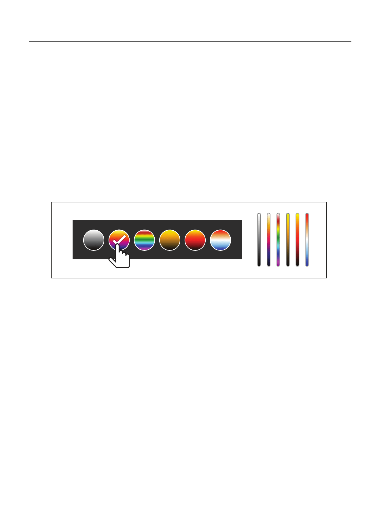
Select a Palette
To change the palette of an image:
1. Tap P.
2. Tap on a palette thumbnail.
3. A check mark shows on the selected palette. The color and temperature range bar on the
display changes according to the selected palette. See Figure 3.
Figure 3. Palette and Range Bar Selection
1.888.610.7664 sales@GlobalTestSupply.com
Fluke-Direct.com

Thermal Imager
Display Menu
19
Display Menu
Use the Display menu to set which features show on the display. To show the Fluke logo on
the display, see Settings Menu. Tab le 12 lists the options in the Display menu.
Marker
Use a fixed-temperature spot marker to show the temperature at the point before you save
an image.
To set a marker:
1. Select m > Markers.
2. Select the number of markers.
The marker symbol (+) shows on the display.
3. Drag the marker or push W / X / Y / Z to move the marker on the image.
4. Push s to set the change and go to the next marker.
5. Continue to set markers. On the final marker push s to exit.
On the camera screen you can tap and drag markers at any time.
Table 12. Display Menu
Option Description
Spot Temp
(Min/Max)
Turn on or turn off the maximum and minimum temperature
indicators on the display.
The Spot Temperatures are floating HI and LO temperature
indicators that move on the display as the temperature
measurements of the image fluctuate.
Markers
Set the number of fixed-temperature spot markers. See Marker.
Sets a temperature reference mark. See Delta-T.
Spot Boxes
Set the number of temperature measurement zones (boxes) that
centers on a target. See Spot Box.
Center Point
Turn on or turn off the Center point marker and Center point
temperature.
Scale
Turn on or turn off the Scale.
Status Bar
Turn on or turn off the Status bar.
1.888.610.7664 sales@GlobalTestSupply.com
Fluke-Direct.com

TiS55+/TiS75+
Users Manual
20
Delta-T
Use Delta-T to set the center point or a spot marker to use as a temperature reference mark.
The other markers will show the temperature difference from the reference point. At least
one marker must be on to use the Delta-T feature.
To set a temperature reference mark:
1. Select m > Markers > Delta-T.
2. Select the marker to use as the reference, or select the Center Point.
[The temperature shows next to the reference mark
Δ The temperature difference relative to the temperature of the reference mark shows
next to the other spot markers.
Note
If you only have one marker, the reference marker is the Center Point. The Center
Point can be a temperature reference mark, but it cannot be the delta point. It is
either the main reference mark or it is not a delta reference at all.
Spot Box
Use the Spot Box feature to set a temperature measurement zone (box) to center on the
target and to adjust the sizes or position of the box. The box expands or contracts to
different levels within the infrared image. The box shows an approximate maximum (MAX),
average (AVG), and minimum (MIN) temperature measurement in that area.
To set a spot box:
1. Select m > Spot Boxes.
2. Select the number of Spot Boxes.
A white box shows on the display. a toggles between Size and Position.
3. If necessary, push a to select Size.
; shows on the display.
4. Drag to increase or decrease the size of the Spot Box.
Or,
Push:
• W to decrease the vertical size.
• X to increase the vertical size.
1.888.610.7664 sales@GlobalTestSupply.com
Fluke-Direct.com

Thermal Imager
Fluke Connect Menu
21
• Y to decrease the horizontal size.
• Z to increase the horizontal size.
5. Push a to select Position.
: shows on the display.
6. To move the box, drag the center of the box or push W / X / Y / Z.
7. Push s to set the change and go to the next Spot Box.
8. Continue to set Spot Boxes. On the final box push s to exit.
Fluke Connect Menu
Table 13 lists the options in the Fluke Connect menu.
Table 13. Fluke Connect Menu
Option Menu Option Description
Scan Asset ID
NA
Assign images to an asset.
Scan a QR code or barcode attached
to an asset or manually enter an asset
identification. See Asset Identification
(Asset ID).
Save Images to
Fluke Connect Cloud
WiFi
Turn on or turn off WiFi.
WiFi Network
With WiFi enabled, connect the
Product to a WiFi network so you can
sign in to your Fluke Connect account.
Sign in to
Pair to Fluke Connect
Tools
On/Off
Turn on to put the Imager into Fluke
Connect Pairing mode. See Fluke
Connect Tools.
Pair Hotspot to Fluke
Connect
WiFi Hotspot
Uses the Product to create a wireless
Hotspot when no WiFi network exists.
See Fluke Connect Wireless System.
WiFi Hotspot Settings
Save Images to Shared
Folder
WiFi
Turn on or turn off WiFi.
WiFi Network
With WiFi enabled, connect the
Product to a WiFi network so you can
sign in to a shared folder on a
network. See Save Images to Shared
Folder.
Shared Folder
1.888.610.7664 sales@GlobalTestSupply.com
Fluke-Direct.com

TiS55+/TiS75+
Users Manual
22
Asset Identification (Asset ID)
Use Asset ID to save and organize images by asset like a motor or electrical panel. Use a
barcode, QR code, or other unique identification as a tag to attach to images. When in
camera mode, the asset ID shows on the display and looks like . Make Asset IDs
unique to each asset.
Assign Asset ID Tag with a QR Code or Barcode
To save images to an asset with a QR code or barcode:
1. Select F > Scan Asset ID.
2. Focus a QR code or barcode in the white box on the display.
3. When the Product detects and scans a barcode, tap Use Barcode or Use QR Code. If
the Product cannot detect a barcode or QR code, manually enter a unique asset ID. See
Assign Asset ID Tag Manually.
The display returns to camera mode, and the barcode or QR code number shows on the
display.
4. Capture an image.
Assign Asset ID Tag Manually
To manually enter a unique asset ID:
1. Select F > Scan Asset ID.
2. Tap Manual Entry.
A keyboard opens on the display.
3. Enter a unique asset identification.
4. Tap Save.
The display returns to camera mode, and the asset ID shows on the display.
Exit an Asset ID Tag
To exit out of an asset ID and save images without an asset ID:
1. Tap the asset ID that looks like on the display.
2. Tap Exit Asset ID xxxxx (where xxxxx is the name of the asset ID).
The display returns to camera mode, and the asset ID does not show on the display.
1.888.610.7664 sales@GlobalTestSupply.com
Fluke-Direct.com

Thermal Imager
Fluke Connect Menu
23
Assign a Different Asset ID Tag
To exit out of an asset ID and save images with a different asset ID:
3. Tap the asset ID that looks like on the display.
4. Tap D Scan New Asset ID.
5. Assign a new asset ID. See Asset Identification (Asset ID).
Fluke Connect Tools
Use the Imager to wirelessly connect to Fluke Connect-supported tools to:
• View the live measurement of each tool.
• Capture the measurement of each tool in .is2 and .is3 images.
To discover a Fluke Connect-supported tool:
1. Turn on each wireless tool and make sure the wireless feature is enabled. See the
documentation of each tool for more information about how to use the tool.
2. Turn on the Imager.
3. Select f > Pair to Fluke Connect Tools.
4. Select On.
The Imager starts to scan and presents a list with the ID and name of available tools
found within 20 m without obstructions (open air) or within 6.5 m with obstructions
(sheetrock wall). You can expect a short delay before the scan is complete.
The Fluke Connect button on each wireless tool will flash.
5. On the Imager, select the tool name.
6. For each tool, tap the tool or push s to select the tool.
The Imager shows the tool in the My Tools list as connected. The tool shows with the
current reading.
The Fluke Tool shows an ID (Identification) number for reference to the list on the
Imager.
7. Push s to return to the Camera mode.
The readings from the tool show on the display. Tap the tool readings on the Imager to
return to the Pair Fluke Connect Tools menu.
1.888.610.7664 sales@GlobalTestSupply.com
Fluke-Direct.com
TiS55+/TiS75+
Users Manual
24
To disconnect from a connected tool:
1. On the Imager, tap the tool.
2. Tap Forget.
The tool shows on the Available Tools list. The tools on the My Tools list will re-order, if
necessary.
3. Select On.
To disconnect all tools, restart the camera.
If the tool goes out of range, the tool shows no reading. On the My Tools list, the tool shows
as not connected. Tap the tool to acknowledge (OK) or remove the tool (Forget Tool).
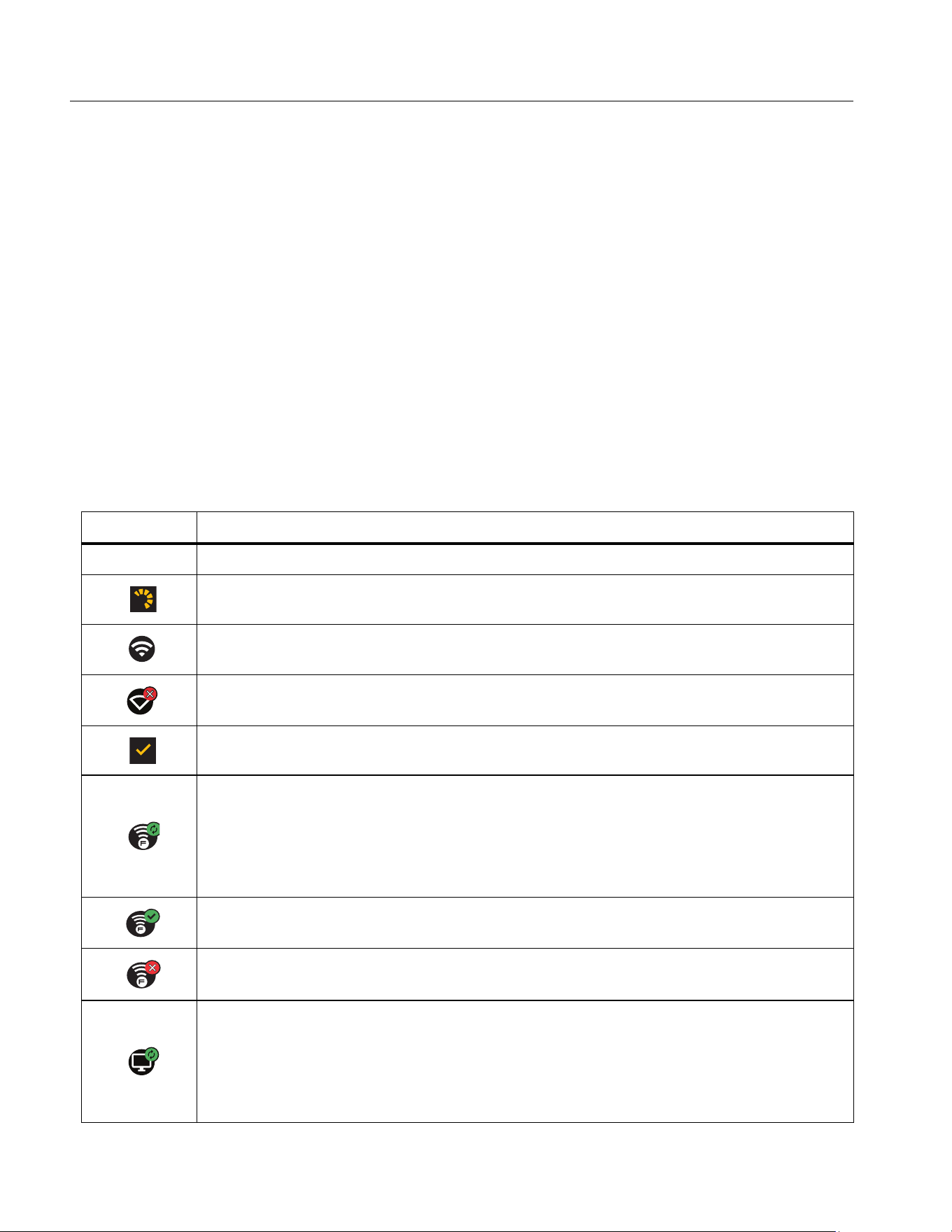
Connection Icons
Icons show the status of the Product connection. Table 1 4 explains the icons.
Table 14. Connection Icons
Icon Description
No icon
WiFi is not on.
In a menu, the Product is attempting to connect to a WiFi network.
The Product is connected to a WiFi network.
WiFi is on, but the Product is not connected to a WiFi network.
In a menu, shows beside the network name that the Product is connected to.
WiFi is on, and the Product is attempting to connect to a Fluke Connect
account.
Or,
Images are saving to a Fluke Connect account.
WiFi is on, and the Product is connected to a Fluke Connect account.
The Product is not connected to a Fluke Connect account.
WiFi is on, and the Product is attempting to connect to a shared folder on a
network server.
Or,
Images are saving to a shared folder.
1.888.610.7664 sales@GlobalTestSupply.com
Fluke-Direct.com

Thermal Imager
Fluke Connect Menu
25
Save Images to Fluke Connect Cloud
When the Product is connected to a WiFi network, you can sign into your Fluke Connect
account on the Product and use Fluke Connect Instant Upload. When you use
Fluke Connect Instant Upload, the images you take with the Product automatically upload to
your Fluke Connect account in the Fluke Cloud. You can view the images saved in the
Fluke Cloud on the Fluke Connect website without the mobile device and Product connected
to each other.
Note
The Instant Upload feature may not work on all networks or with all devices due to
the security profiles on different networks.
Sign in to Fluke Connect WiFi Network
Use the WiFi Network setting to connect the Product to a WiFi network and to sign into a
Fluke Connect account on the Product.
To turn on the WiFi Network feature:
1. Select F > Save Images to Fluke Connect Cloud > WiFi > On.
2. Push WiFi Network to scan for available networks within range of the Product.
3. Tap on a network to connect to it.
4. If you are prompted to enter a user name and password:
a. Use the keyboard to enter a new user name, or tap 6 to see a list of recently used
user names.
b. Tap Next.
c. Use the keyboard to enter a password.
d. Tap Sign In.
e. Tap OK.
The display returns to the Save to Fluke Connect menu.
5. Sign in to Fluke Connect. See Sign in to Fluke Connect Cloud.
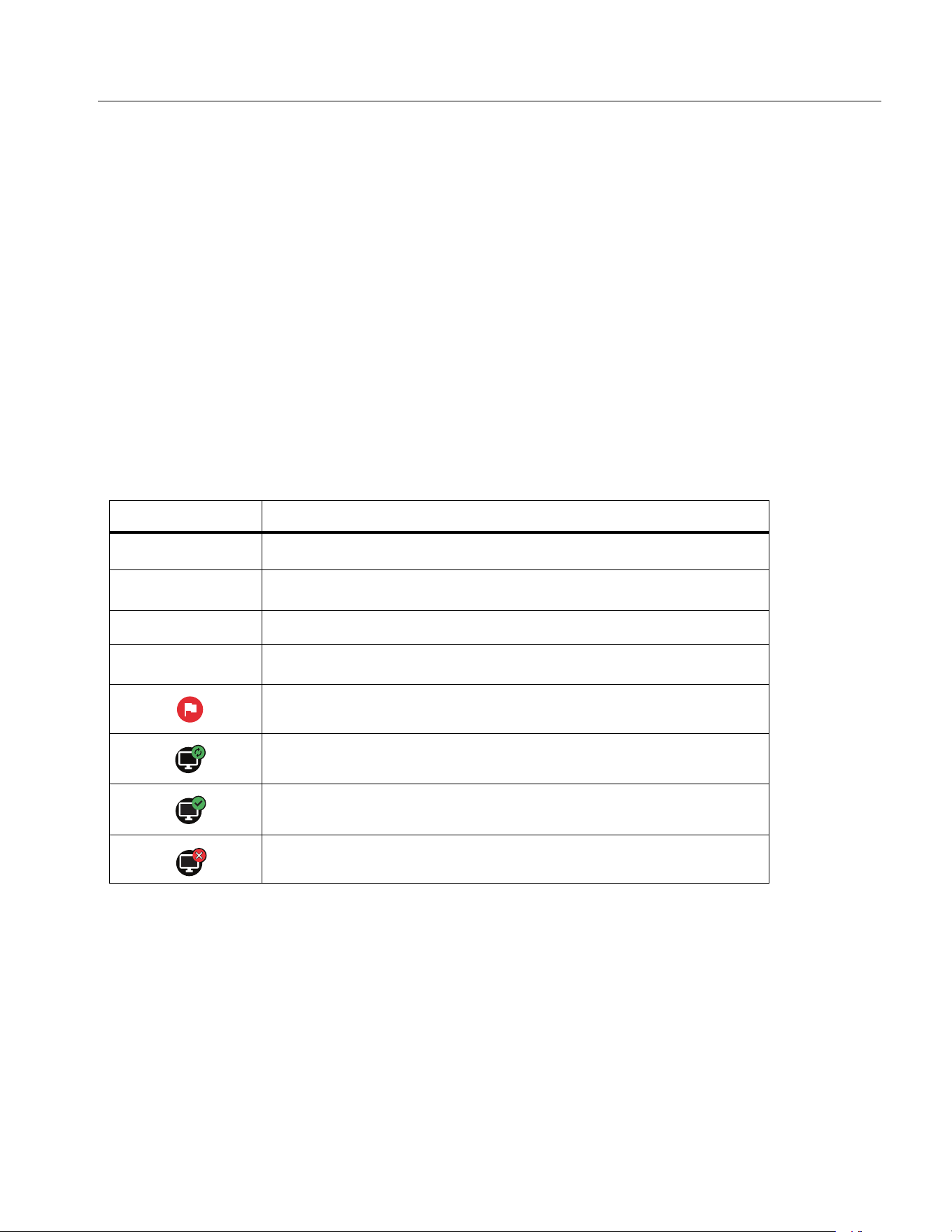
WiFi is on, and the Product is connected to a shared folder on a network
server.
The Product is not connected to a shared folder on a network server.
Table 14. Connection Icons (cont.)
Icon Description
1.888.610.7664 sales@GlobalTestSupply.com
Fluke-Direct.com

TiS55+/TiS75+
Users Manual
26
Sign out of Fluke Connect WiFi Network
To sign out of a WiFi network:
1. Select F > Save Images to Fluke Connect Cloud > WiFi Network.
2. Tap the name of the connected network.
3. Tap Forget Network.
4. Tap F to return to camera mode.
Sign in to Fluke Connect Cloud
To sign in to your Fluke Connect account:
1. Turn WiFi on and connect to a WiFi network. See Sign in to Fluke Connect WiFi Network.
2. Tap Sign in to Fluke Connect.
3. Use the keyboard to enter an email address, or tap 6 to see a list of recently used email
addresses.
4. Tap Next.
5. Use the keyboard to enter a password.
6. Tap Sign In.
7. Tap OK to return to camera mode to capture images.
Sign out of Fluke Connect Cloud
To sign out:
1. Select F > Save Images to Fluke Connect Cloud > Sign in to Fluke Connect.
2. Tap Sign Out.
The display returns to the Save to Fluke Connect menu.
3. Tap F.
1.888.610.7664 sales@GlobalTestSupply.com
Fluke-Direct.com

Thermal Imager
Fluke Connect Menu
27
Fluke Connect Wireless System
The Product supports the Fluke Connect Wireless System. The Fluke Connect system
wirelessly connects your Fluke test tools with an app on a mobile device. It shows images
from the Product on your mobile device.
Note
The Fluke Connect system is not available in all countries.
Pair Hotspot to Fluke Connect
Use the Product to create a wireless Hotspot when no WiFi network exists. You can use the
Hotspot to download saved pictures or stream live images from the Product to a mobile
device with the Fluke Connect app.
Note
WiFi is for indoor use only in Kuwait, Chile, and United Arab Emirates.
To create a Hotspot, pair the Product to the Fluke Connect app. See Pair to Mobile App.
To change the hotspot settings:
1. Select F > Pair Hotspot to Fluke Connect > WiFi Hotspot Settings.
2. Select an option:
• Name (SSID) to change the SSID
• Password to turn on or turn off the password or to change the password
• Channel to change the channel
3. Use the keyboard to enter the information for the option.
4. Tap Save to use the Product.
Pair to Mobile App
The Fluke Connect app works with Apple and Android products. The app is available for
download from the Apple App Store and Google Play.
The Fluke Connect app will be available after initial release. When the app becomes
available, you can download the app from the Apple App Store and Google Play.
To use the Fluke Connect app with the Product:
1. On the Product, select F > Pair Hotspot to Fluke Connect > WiFi Hotspot > On.
2. On the mobile device:
1.888.610.7664 sales@GlobalTestSupply.com
Fluke-Direct.com

TiS55+/TiS75+
Users Manual
28
a. Go to Settings > Wi-Fi.
b. Select the Wi-Fi network that begins with Fluke....
3. On the Fluke Connect app, select Thermal Imager from the list.
The pictures you take with the Product are saved on your mobile device and on the
Product.
Note
To save images to the Fluke Connect app, set the file format to .is2 (see Settings
Menu).
4. On the Product:
a. Capture an image.
The image is now in the memory buffer.
b. Tap Save to save the image and view the image on the phone app.
Save Images to Shared Folder
When the Product is connected to a WiFi network, you can select a folder on a server. The
images you take with the Product save to the Product and automatically upload to the
selected folder on the server. Anyone with access to the folder on the server can view the
images immediately.
Note
The Shared Folder feature may not work on all networks or with all devices due to
the security profiles on different networks.
Sign in to Shared Folder WiFi Network
Use the WiFi Network setting to connect the Product to a WiFi network and to sign into a
Fluke Connect account on the Product.
To turn on the WiFi Network feature:
1. Select F > Save Images to Shared Folder > WiFi > On.
2. Tap WiFi Network to scan for available networks within range of the Product.
3. Tap on a network to connect to it.
4. If you are prompted to enter a user name and password:
a. Use the keyboard to enter a new user name, or tap 6 to see a list of recently used
user names.
1.888.610.7664 sales@GlobalTestSupply.com
Fluke-Direct.com

Thermal Imager
Fluke Connect Menu
29
b. Tap Next.
c. Use the keyboard to enter a password.
d. Tap Sign In.
e. Tap OK.
The display returns to the Save to Fluke Connect menu.
5. Sign in to a shared folder. See Sign in to Shared Folder.
Sign out of Shared Folder WiFi Network
To sign out:
1. Select F > Save Images to Shared Folder > WiFi Network.
2. Tap the name of the connected network.
3. Tap Forget Network.
4. Tap F to return to camera mode.
Sign in to Shared Folder
Note
To learn how to create or access a shared folder on a network, contact your IT
department.
To use the Product to sign in to a shared folder on a network:
1. Turn WiFi on and connect to a WiFi network. See Sign out of Shared Folder WiFi
Network.
2. Tap Shared Folder > File Path.
3. Use the keyboard to enter a file path, or tap 6 to see a list of recently used file paths.
After you enter a file path for the first time, the field automatically shows the last used file
path.
1.888.610.7664 sales@GlobalTestSupply.com
Fluke-Direct.com

TiS55+/TiS75+
Users Manual
30
4. Tap Save.
Depending on your security environment, enter a username and password:
a. Tap Username and Password.
b. Use the keyboard to enter a new user name, or tap
6 to see a list of recently used
user names.
c. Tap Next.
d. Use the keyboard to enter a password.
e. Tap Next.
f. Tap Sign In.
5. Tap Connect.
6. Tap OK.
If images in the Product memory have not been saved to a shared folder, a message
prompts you to save the images.
• Tap Save Images to save images to the shared folder.
Or,
• Tap Not Now to save the images to the shared folder another time.
The display returns to the Save to Shared Folder menu.
7. Tap
F to return to camera mode to capture images.
Note
Keep the Product on and stay in the range of the WiFi network until images are
uploaded. If the connection is lost before all the images are saved to the shared
folder, u shows on the title bar of the Memory menu. Sign in to the shared folder
again and tap u to upload the images.
Sign out of Shared Folder
To sign out:
1. Select F > Save Images to Shared Folder > Shared Folder > Disconnect.
The display returns to the Save to Shared Folder menu.
2. Tap F to return to camera mode.
1.888.610.7664 sales@GlobalTestSupply.com
Fluke-Direct.com

Thermal Imager
Settings Menu
31
Settings Menu
Table 15 is a list of the options in the Settings menu.
Table 15. Settings Menu
Option Menu Option Description
Capture
Settings
Video
See Capture Settings.
Auto Capture
See Auto Capture.
Bluetooth
Headset
See Bluetooth Headset.
Data
Streaming
Turn on Data Streaming to connect to PC software.
Backlight
NA Slider to adjust the backlight
File Format
IS2
Saves images as a .is2 file.
Choose the .is2 file format when image modification
and maximum resolution is needed.
The .is2 file format consolidates the infrared image,
radiometric temperature data, visible image, voice
annotation, and photos from the IR-PhotoNotes photo
annotation system into a single file. To customize or
separate the visible and infrared images, use
SmartView software or the Fluke Connect app.
JPEG
Saves images as a .jpg file.
Choose the .jpg file format for images with the smallest
file size, where modification is not needed, and image
quality and resolution are not as important.
Visible Light
Camera
Resolution
Sets the megapixels (MP) on the visual light camera.
(5.0 Megapixel or 1.3 Megapixel)
Units
<options>
Sets the temperature units to Celsius or Fahrenheit.
This option is not available in all countries.
Distance Units
Sets the units to use to measure distance. This option
is not available in all countries.
1.888.610.7664 sales@GlobalTestSupply.com
Fluke-Direct.com

TiS55+/TiS75+
Users Manual
32
Auto Off
LCD Time Out
Set the time before the display automatically turns off.
Power Off
Set the time before the Imager automatically turns off.
Note
Auto Off is automatically disabled when the
battery is connected to ac power.
Date
<options> Set the date format and the date. See Date.
Time
<options> Set the time format and the time. See Time.
Image Storage
Internal
Memory
SD Card
Set the location to save images.
Secondary
Trigger
Laser
(default) Set the function of the secondary (black)
trigger to the laser function. The laser is active only
while pushing the trigger.
Scan Asset ID
Set the function of the secondary (black) trigger to the
QR code reader function. (Scan Asset ID) Use the QR
code reader for Asset Tagging.
Logo
NA Show or hide the Fluke logo on the display.
Language
<options> Set the language to use on the display.
Decimal
Separator
<options> Set the decimal separator to comma or decimal point.
Localization
<options> Set the decimal separator to comma or decimal point.
Change
Filename
NA
Change the default filename that starts with IR_ to a
different 3-character prefix with the touch screen
keyboard.
Reset to
Factory
Defaults
NA
Erase all user-set preferences and restores the factory
default settings. This does not erase images in
memory.
Certificates
NA
Show information about the wireless certificates of the
Product.
Licenses
NA
View information about the version, certificates, and
Open Source Software Licenses of the Imager.
Version
NA Firmware version of the camera.
Table 15. Settings Menu (cont.)
Option Menu Option Description
1.888.610.7664 sales@GlobalTestSupply.com
Fluke-Direct.com

Thermal Imager
Settings Menu
33
Capture Settings
Video
You can record video with and without audio. See Table 16. The thermal scene and
complexity of the recorded data affects the amount of time available to record a video.
Record Video
To quickly record a video, push and hold the primary trigger for 2 seconds. Release the
button once the recording starts.
To record:
1. Select s > Capture Settings > Record Video only OR Record Video/Audio.
2. Push the primary trigger.
3. The Imager starts the recording.
4. To pause the recording, push the primary trigger.
5. To restart the recording, push the primary trigger again.
6. To save the video, push s.
7. To delete the video, push d and then tap Delete.
Table 16. Video
Option Description
Record Video Only
Start a video recording when the primary trigger is
pressed. See Record Video.
Record Video/Audio
Requires a Bluetooth headset. Starts a video recording
with audio. See Record Video.
Video File Fomat
IS3
Save videos as an .is3 file with radiometric video capture.
Choose the .is3 video format when video modification and
maximum resolution is needed.
To edit the .is3 video file, use SmartView software or the
Fluke Connect app.
AVI
Save videos as an .avi file with .mpeg encoding.
Choose the .avi video format when video modification is
not required. The file retains the video settings at the time
the video was captured and saved.
1.888.610.7664 sales@GlobalTestSupply.com
Fluke-Direct.com

TiS55+/TiS75+
Users Manual
34
View Video
To play a video:
1. Push m.
2. Select a file to play. All video files show as a thumbnail.
3. Tap the play button.
4. To pause or restart push s.
5. To delete, push W and tap the delete icon and then tap Delete to confirm.
Auto Capture
Use Auto Capture to set parameters so the camera will automatically take images.
To configure Auto Capture:
1. Select s > Capture Settings > Auto Capture.
2. Choose the capture frequency.
• To capture images at a specified interval, select Interval. Use the arrows to set the
interval time.
• To capture a set number of images, select Image Count > Number of Images. Use
the arrows to select the number of images. The default number is 5.
• To capture images until the memory is full, select Image Count > Maximum Memory.
• Choose the trigger that will start the automatic image capture.
• To automatically capture images based on temperature, select Temp Trigger. Select
whether the trigger will be Over or Under the specified temperature. Use the arrows to
set the specified temperature. Select which reference point where the temperature
will be monitored.
• To start the Auto Capture manually, select Manual Trigger.
Start manual trigger Auto Capture:
1. Select s > Capture Settings > Start Capture.
(appears on the display.
2. Push the primary trigger.
1.888.610.7664 sales@GlobalTestSupply.com
Fluke-Direct.com

Thermal Imager
Settings Menu
35
3. The Imager will take images as configured.
Start temperature trigger Auto Capture:
1. Postion the camera and set the markers and spot boxes as required.
2. Select s > Capture Settings > Start Capture.
(appears on the display.
The Imager will take images when the temperature of the marker, center point, or spot
box reaches the trigger condition.
Bluetooth Headset
Connect a Bluetooth Headset to support audio features.
To connect a Bluetooth Headset:
1. Put the Bluetooth Headset into pairing mode.
2. On the Imager, select s > Bluetooth Headset > On.
The Imager starts to scan and presents a list with of available devices. You can expect a
short delay before the scan is complete.
Tap the headset to select it.
The headset willl connect and show on the My Devices list. A headset icon displays in
Camera mode.
Date
The date shows as: MM/DD/YY or DD/MM/YY.
To set the date:
1. Select s > Date.
2. Select MM/DD/YY or DD/MM/YY.
3. Push s to set the new format.
4. Select Set Date.
5. Push s to open the Set Date menu.
6. Push
/
to select Day, Month, or Year.
7. Push
/
to change the day, month, or year.
8. Push s to set the date and exit the menu.
1.888.610.7664 sales@GlobalTestSupply.com
Fluke-Direct.com

TiS55+/TiS75+
Users Manual
36
Time
Time shows as: 24 hour or 12 hour.
To set the time format:
1. Select s > Time.
2. Select 24 hour or 12 hour.
3. Push s to set the time format.
4. Select Set Time.
5. Push s to open the Set Time menu.
6. Push
/
to select Hours or Minutes.
7. If you selected the 12 hour format, select AM or PM.
Image Annotation
You can annotate images with text and audio. See Table 17.
Text Notes
Notes are stored with the image so you do not need to collate multiple files later. To add,
edit, and delete notes, use the keyboard that opens on the display.
Images that have text notes show with the note icon (N).
Notes with Single Image
Choose a method to add, edit, or delete a note for an image:
• For an image in the memory buffer: Select Edit > Text Note.
• For a saved image: Open the image in fullscreen mode.
1. Tap N. If needed, tap first.
If no notes are saved with the image, a keyboard opens on the display.
Table 17. Annotations
Icon Option Description
N
Text Note
Add text notes. See Text Notes.
Audio Note
Add audio notes. See Audio Notes.
C
IRPhotoNotes
Add photo images from the visible light camera. See
IR-PhotoNotes.
h
Flag Image
Mark an image for review. See Flag an Image.
1.888.610.7664 sales@GlobalTestSupply.com
Fluke-Direct.com

Thermal Imager
Image Annotation
37
2. Use the keyboard to enter a message.
3. Tap Save.
If a note is saved with the image, a list of notes opens on the display.
4. To add another note to the image, tap , use the keyboard to add the new note, and tap
Save.
5. To edit a note, tap on a note, use the keyboard to edit it, and tap Save. If needed, scroll
down to see all the notes.
6. To delete a note, tap on a note, tap Delete, and tap Delete again.
Add a Note to Multiple Images
To add a note to multiple images at the same time:
1. Select m > > Add a Note to Multiple Images.
The display returns to the memory gallery.
2. Tap an image to select it. Tap an image again to clear the selection.
The border and filename text color change to yellow.
3. Repeat for each additional image.
4. Tap Add Note.
A keyboard opens on the display.
5. Use the keyboard to enter a message.
6. Tap Save.
Audio Notes
Audio notes require an .is2 image and a Bluetooth headset.
Images that have audio notes show with the audio icon ().
Record Audio Notes
Choose a method to add, edit, or delete a note for an image:
• For an image in the memory buffer: Select Edit > Audio Note.
• For a saved image: Select m > image > ... > Audio Note.
1. Tap Record and begin recording.
You can record up to 60 seconds of audio.
To cancel, tap Cancel.
1.888.610.7664 sales@GlobalTestSupply.com
Fluke-Direct.com

TiS55+/TiS75+
Users Manual
38
2. To pause, tap Pause.
You can save or playback while the recording is paused.
• To save, tap Save. The recording is saved.
• To playback, tap Play. You can tap Pause to pause the playback or Record to
resume recording.
3. To save the recording tap Pause and then tap Save.
The Audio note is saved. The menu shows the number of seconds of the Audo note.
Review Audio Notes
You can review the audio note from the memory buffer.
1. Select Edit > Audio Note.
2. To listen to the recording, tap Play.
3. To record additional audio, tap Append.
4. To delete the audio note, tap Delete.
You can save or playback while the recording is paused.
• To save, tap Save. The recording is saved.
• To playback, tap Play. You can tap Pause to pause the playback or Record to
resume recording.
IR-PhotoNotes
Use the IR-PhotoNotes photo annotation system to capture visible images of various
objects, text, or other information that is related to the analysis and reporting of an infrared
image. A visible image is a clear digital photo and does not use infrared technology.
Examples of possible annotations include motor name plates, printed information or warning
signs, larger views of the environment or room, and related equipment or objects. IR-
PhotoNotes images are only available in the .is2 file format and are stored in the file so you
do not need to collate multiple files at a later time.
Images that have IR-PhotoNotes show with the icon (C).
1.888.610.7664 sales@GlobalTestSupply.com
Fluke-Direct.com

Thermal Imager
Image Annotation
39
Make IR-PhotoNotes
Choose a method to add, edit, or delete a note for an image:
• For an image in the memory buffer: Select Edit > IRPhotoNotes.
• For a saved image: Select m > image > ... > IRPhotoNotes.
The Imager opens the Visible Light Camera so you can take an image.
1. For each image to save, push the primary trigger to take an image.
Note
The TiS55+ can take one IR-PhotoNote only.
2. To stop taking images and return to the menu, tap Done.
The images are saved and the menu shows the number of images.
Review IR-PhotoNotes
For an image in the memory buffer:
1. Select Edit > IRPhotoNotes.
The Imager opens the images.
2. Tap an image to select the image (TiS75+).
3. To delete an image, tap the trash icon t, and then tap Delete.
The images are saved and the menu shows the number of images.
4. To take another image, tap the add icon , and then press the primary trigger to take
the photo.
Flag an Image
Flag an image to review later. The flag feature is a toggle switch.
To flag an image, open an image in full screen mode, and tap H. The flag icon changes to
. Tap again to remove the flag.
1.888.610.7664 sales@GlobalTestSupply.com
Fluke-Direct.com

TiS55+/TiS75+
Users Manual
40
Manage Images
You can delete images from Memory or during review.
Delete an Image
To delete only one image:
1. Open an image in full-screen mode.
2. Tap .
3. Tap Delete.
Delete Multiple Images
To delete multiple images at the same time:
1. Select m > > Delete Multiple Images.
The display returns to the memory gallery.
2. Tap an image to select it. Tap an image again to clear the selection.
The border and filename text color change to yellow.
3. Repeat for each additional image.
4. Tap Delete Images.
5. Tap Delete.
Delete All Images
To delete all of the images at the same time:
1. Select m > > Delete All Images.
2. Tap Delete.
1.888.610.7664 sales@GlobalTestSupply.com
Fluke-Direct.com
Thermal Imager
Memory Menu (Memory Gallery)
41
Memory Menu (Memory Gallery)
Note
When the memory is 90 % full, a yellow message bar shows at the top of the display.
When the memory is full, the message bar changes to red. To capture more images
when the internal memory is full, save the images to an external memory device and
delete the images from the Product.
Images are saved to the internal memory storage. Use the Memory menu to view, edit, or
delete images. Images are organized by the date they were captured with the newest
images at the top.
When additional information has been saved with an .is2 file, an icon shows with the preview
file. Tab le 1 8 shows the icons.
Table 18. Image Icons
Icon Description
1
Asset ID
n
Text Note
Audio Note
C
IR-PhotoNote
Asset flag
Image is saving to a shared folder
Image saved to a shared folder
Image is not saved. Return to WiFi range to save.
1.888.610.7664 sales@GlobalTestSupply.com
Fluke-Direct.com

TiS55+/TiS75+
Users Manual
42
View Image
To open an image in fullscreen mode:
1. Push m.
2. If needed, touch the display and slide up or down to view all the images.
3. Tap on a thumbnail or preview image to view the image fullscreen.
A toolbar briefly opens on the top of the display. Tap on the image to open or close the
toolbar.
Asset ID
Use the image toolbar to add or remove an asset ID from an image that is saved in memory.
See Asset Identification (Asset ID).
To add an asset ID to an image:
1. Open an image in fullscreen mode.
2. Tap D.
3. Assign an asset ID. See Asset Identification (Asset ID).
To remove an asset ID from an image:
1. Open an image in fullscreen mode.
2. Tap the asset ID that looks like on the display.
3. Tap Remove.
The display returns to the image in fullscreen mode, and the asset ID does not show on
the display.
Fluke Connect Desktop Software
Fluke Connect desktop software for a PC is available to use with the Product and contains
features to analyze images, organize data and information, and make professional reports.
Use Fluke Connect software to:
• Review notes, asset IDs, and flags.
• Export IR and visible images.
• Edit .is2 image files.
• Update the firmware with new features.
1.888.610.7664 sales@GlobalTestSupply.com
Fluke-Direct.com

Thermal Imager
Accessories
43
Download Fluke Connect Software
To download Fluke Connect desktop software:
2. On the website, follow the instructions to download the software to the PC.
3. On the PC, follow the instructions to install Fluke Connect software.
4. Administrator privileges are required for the installation.
5. Restart the PC when installation is complete.
Update Firmware
To update the firmware:
1. On the PC, open Fluke Connect software.
2. Connect one end of the USB cord into your PC and the other end of the USB cord into
the Product.
Fluke Connect software recognizes the connection with the Product. Windows
automatically installs the device driver for use with the Product.
3. On the PC:
a. Select Yes if prompted to download a firmware update file onto the PC.
b. Select the Product from the list on the left.
c. Select Yes if prompted to download a firmware update to the Product.
4. On the Product, Tap Ok.
To complete the firmware update, the Product turns off.
5. To use the new firmware, turn on the Product.
Accessories
1.888.610.7664 sales@GlobalTestSupply.com
Fluke-Direct.com

TiS55+/TiS75+
Users Manual
44
Maintenance
The Product requires minimum maintenance.
Clean the Case
Clean the case with a damp cloth and a weak soap solution. Do not use abrasives, isopropyl
alcohol, or solvents to clean the case.
Lens Care
W Caution
To prevent damage to the infrared lens:
• Carefully clean the infrared lens. The lens has a delicate anti-reflective coating.
• Do not clean the lens too vigorously because this can damage the anti-
reflective coating.
To clean the lens:
1. Use a pressurized can of air or a dry nitrogen-ion gun, if available, to blow off the
particulates from the lens surface.
2. Soak a lint-free cloth in a commercial lens cleaning liquid that contains alcohol, ethyl
alcohol, or isopropyl alcohol.
3. Squeeze the cloth to remove excess liquid.
4. Wipe the lens surface in one circular motion and discard the cloth.
5. If needed, repeat with a new lint-free cloth.
Battery Care
To get the best performance from the lithium-ion battery:
• Do not charge the Product for more than 24 hours as reduced battery life may result.
• Charge the Product for at least 2.5 hours every six-months for maximum battery life.
Without use, the battery will self-discharge in approximately six months.
1.888.610.7664 sales@GlobalTestSupply.com
Fluke-Direct.com

Thermal Imager
Maintenance
45
Charge Batteries
W Caution
To prevent damage to the Imager:
• Do not store the batteries in extreme cold environments.
• Do not attempt to charge the batteries in extreme cold environments.
~ W Caution
Do not incinerate the Product and/or battery.
Before you use the Imager for the first time, charge the battery for at least 2.5 hours. The
battery status shows on the five-segment charge indicator.
Note
New batteries are not fully charged. Two to ten charge/discharge cycles are
necessary before the battery charges to its maximum capacity.
To charge the battery, use one of the options that follow.
Two-Bay Battery Charger Base
To charge the battery in the charger base:
1. Connect the ac power supply to the ac wall outlet and connect the dc output to the
charger base.
2. Put one or two smart batteries into bays of charger base.
3. Charge batteries until charge LEDs on charger base are a solid green.
4. Remove smart batteries and disconnect the power supply when batteries are fully
charged.
AC Power Socket on Imager
Note
Make sure that the Imager is near room temperature before you connect it to the
charger. See the charging temperature specification. Do not charge in hot or cold
areas. When you charge in extreme temperatures, battery capacity may be
decreased. When you charge in extreme temperatures, the battery may not charge.
To charge the battery with the ac power socket on the Imager:
1. Connect the ac power adapter into an ac wall outlet and connect the other end to the ac
power socket on the Imager. bz flashes on the display while the battery charges.
2. Charge until the charge indicator on the display does not flash.
1.888.610.7664 sales@GlobalTestSupply.com
Fluke-Direct.com

TiS55+/TiS75+
Users Manual
46
If you remove the Imager from the charger before a full charge shows, it can have a
reduced run-time.
3. Disconnect the ac power adapter when the smart battery is fully charged.
Optional 12 V Vehicle Charger
W Caution
To prevent damage to the Imager, remove it from the dc car charger before you
start or jump start the vehicle.
To use the 12 V vehicle charger to charge the battery:
1. Connect the 12 V adapter into the 12 V accessory socket of the vehicle.
2. Connect the other end to the ac power socket of the Imager.
bz flashes on the display while the battery charges.
3. Charge until the charge indicator on the display does not flash.
4. Disconnect the 12 V adapter and Imager when battery is fully charged.
Radio Frequency Data
See Table 15 for instructions on how to access digital copies of the Certificate IDs on the
Imager.
1.888.610.7664 sales@GlobalTestSupply.com
Fluke-Direct.com