Loading ...
Loading ...
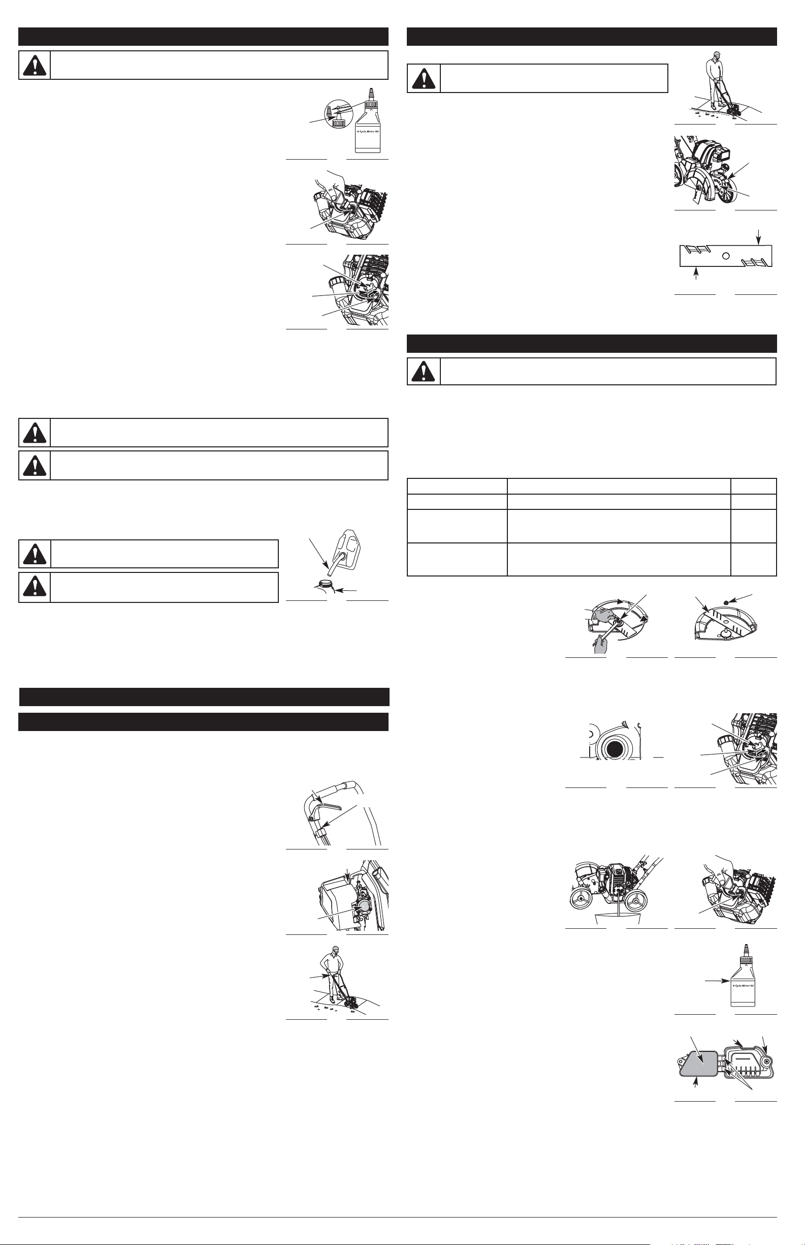
RECOMMENDED OIL TYPE
Using the proper type and weight of oil in the crankcase is extremely important.
Check the oil before each use and change the oil regularly. Failure to use the correct
oil, or using dirty oil, can cause premature engine wear and failure.
Use a high-quality SAE 30 weight oil of API (American Petroleum Institute) service
class SF, SG, SH.
ADDING OIL TO CRANKCASE: INITIAL USE
NOTE: This unit is shipped without oil. In order to avoid damage to the unit, put
oil in the crankcase before attempting to start the unit.
The unit is supplied with one 3.04 fluid oz. (90 ml) bottle of SAE 30 SF, SG, SH oil (Fig. 1).
NOTE: Save the bottle of oil. It can be used to measure the correct amount during
future oil changes. See Changing the Oil.
1. Unscrew the top of the bottle of oil and remove the paper seal covering the
opening. Replace the top. Next, cut the tip off the funnel spout (Fig. 1).
2. Place unit on a flat, level surface.
3. Remove the oil fill plug from the crankcase (Fig. 3).
4. Pour the entire bottle of oil into the oil fill hole (Fig. 2).
NOTE: Never add oil to the fuel or fuel tank.
5. Wipe up any oil that may have spilled and reinstall the oil fill plug.
Check oil before each use and change as needed. Refer to Checking the Oil Level.
RECOMMENDED FUEL TYPE
Old fuel is the primary reason for improper unit performance. Be sure to use fresh,
clean, unleaded gasoline.
NOTE: Dispose of the old gasoline in accordance with federal, state and local
regulations.
NOTE: This is a four cycle engine. In order to avoid damage to the unit, do not
mix oil with gasoline.
Definition of Blended Fuels
Today's fuels are often a blend of gasoline and oxygenates such as ethanol, methanol or MTBE (ether). Alcohol-
blended fuel absorbs water. As little as 1% water in the fuel can make fuel and oil separate or form acids when stored.
Use fresh fuel (less than 30 days old), when using alcohol-blended fuel.
Using Blended Fuels
If choosing to use a blended fuel, or its use is unavoidable, follow recommended precautions:
• Always use fresh unleaded gasoline
• Use the fuel additive STA-BIL® or an equivalent
• Drain tank and run the engine dry before storing unit
3
OIL AND FUEL INFORMATION
STARTING AND STOPPING INSTRUCTIONS
WARNING: OVERFILLING OIL CRANKCASE MAY CAUSE SERIOUS PERSONAL INJURY. Check and
maintain the proper oil level in the crankcase; it is important and cannot be overemphasized. Check the
oil before each use and change it as needed. See Changing the Oil.
Fig. 1
Funnel
Spout
Fig. 2
Oil Fill
Hole
Oil Fill Plug
Fig. 3
O-Ring
Oil Fill Hole
Using Fuel Additives
The use of fuel additives, such as STA-BIL® Gas Stabilizer or an equivalent, will inhibit corrosion and minimize the
formation of gum deposits. Using a fuel additive can keep fuel from forming harmful deposits in the carburetor for up to
six (6) months. Add 0.8 oz. (23 ml) of fuel additive per gallon of fuel according to the instructions on the fuel additive
container. NEVER add fuel additives directly to the unit's gas tank.
FUELING THE UNIT
1. Remove the fuel cap (Fig. 4).
2. Place the gas container’s spout into the fill hole on the fuel tank (Fig. 4) and fill the tank.
NOTE: Do not overfill the tank.
3. Wipe up any gasoline that may have spilled.
4. Reinstall the fuel cap.
5. Move the unit at least 30 ft. (9.1 m) from the fueling source and site before starting the engine.
Fig. 4
Gas Can Spout
Fuel Tank
WARNING: DO NOT USE E85 FUEL IN THIS UNIT. It has been
proven that fuel containing greater than 10% ethanol will likely
damage this engine and void the warranty.
WARNING:
Remove fuel cap slowly to avoid injury from fuel spray.
Never operate the unit without the fuel cap securely in place.
WARNING: Gasoline is extremely flammable. Ignited vapors may explode. Always stop the engine
and allow it to cool before filling the fuel tank. Do not smoke while filling the tank. Keep sparks and open
flames at a distance from the area.
WARNING: Add fuel in a clean, well ventilated outdoor area. Wipe up any spilled fuel immediately.
Avoid creating a source of ignition for spilt fuel. Do not start the engine until fuel vapors dissipate.
IF USING THE OPTIONAL ELECTRIC STARTER OR POWER START BIT™ ACCESSORY
HOW TO START THE UNIT USING THE ELECTRIC STARTER OR POWER START BIT™ ACCESSORY
NOTE: This unit can use an Electric Starter or Power Start Bit™ optional accessory!
Please refer to the Electric Starter or Power Start Bit™ operator’s manual for proper use of this feature.
(Items Sold Separately! Please refer to page 4 of this manual about purchasing these accessories.)
STARTING INSTRUCTIONS
1. Check the oil level in the crankcase. Refer to Checking the Oil Level.
2. Fill the fuel tank with fresh, clean unleaded gasoline. Refer to Fueling the Unit.
NOTE: There is no need to turn the unit on. The On/Off Control is in the ON (I)
position at all times (Fig. 5).
IF COLD... In cold weather conditions (below 40°F), push the red cold weather start
lever (Fig. 6) down to the closed position and continue to step 3. DO NOT
push this lever down if the temperature is above 40°F.
NOTE: DO NOT squeeze the throttle control until step 9.
3. Fully press and release the primer bulb 10 times, slowly. Some amount of fuel
should be visible in the primer bulb (Fig. 6). If fuel cannot be seen in the bulb,
press and release the bulb until fuel is visible.
4. Place the electric starter or Power Start Bit™ into the back of the unit. Refer to the
Operation section of the Electric Starter or Power Start Bit™ operator’s manual.
5. Press and hold the ON (I) button of the Electric Starter or Power Start Bit™
equipped drill in intervals no longer than 2 seconds each until the unit starts.
IF COLD... In cold weather conditions (below 40°F), pull the red cold weather start
lever back up to the open position after the unit starts.
6. Remove the electric starter or drill from the unit.
7. Wait 60 seconds.
8. Stand in the starting position (Fig. 7). Tip the unit back so the blade does not
touch the ground.
9. Squeeze the throttle control and allow the engine to warm up for 30 to 60
seconds. The unit may be used during this time.
IF... The engine does not start, go back to step 3.
IF... The engine stops while squeezing the throttle, go back to step 4.
STOPPING INSTRUCTIONS
1. Release the throttle control and allow the engine to cool down by idling.
2. Press and hold the On/Off Control in the OFF (O) position until the unit comes to a complete stop. (Fig. 5)
Fig. 5
Throttle
Control
On/Off
Control
Fig. 6
Red Cold Weather
Start Lever
Primer
Bulb
Fig. 7
Starting
Position
Starter
Rope
OPERATING INSTRUCTIONS
HOLDING THE UNIT
Before operating the unit, stand in the operating position (Fig. 8). Check for the following:
• The operator is wearing eye protection and proper clothing.
• Both hands are holding the handle bar firmly.
• The edger wheel adjusted for proper cut depth as shown in Figure 9 and edger
positioned as shown in Figure 8.
ADJUSTING EDGER CUTTING DEPTH
1. Gently pull the depth adjustment lever away from the wheel bracket (Fig 9).
2. To raise the cutting blade, move the lever toward the front of the wheel bracket
(Fig. 9). Lowering the wheel decreases the cutting depth.
3. To lower the cutting blade, move the lever toward the rear of the wheel bracket.
Raising the wheel increases the cutting depth.
TIPS FOR BEST EDGING RESULTS
• After starting the engine, keep the unit tilted back so the blade does not touch the
ground. Move the unit to the desired location and slowly lower the blade into the
ground.
• Do not force the edger. Edge the first time at a lesser depth (no more than 1/2”
depth cut per pass), then do the area again with a deeper setting.
• Walk the edger at a slow, even pace.
• Check the blade condition (Fig. 10). As it wears it becomes smaller, thus reducing
the cutting depth performance. Replace the blade when it no longer makes
contact with the ground.
WARNING: Always wear eye, hearing, foot and body protection to
reduce the risk of injury when operating this unit.
Fig. 8
Fig. 9
Depth
Adjustment
Lever
Wheel
Bracket
Fig. 10
Blade Edge
Blade Edge
BLADE REPLACEMENT
1. Place the 5/16” Allen wrench in the spindle
hole (Fig. 11).
2. While holding the Allen wrench in place, loosen
the nut with a 15/16” wrench by turning it
counterclockwise (Fig. 11).
3. Re move the nut and blade. Keep the nut for
new blade installation.
4. Install the new blade and nut (Fig. 12).
NOTE: Make sure the blade edges are facing the proper direction (Fig. 12). The unit will not function correctly if the
edger blade is installed backward.
5. While holding the Allen wrench in the spindle hole, tighten the nut by turning the wrench clockwise until tight (Fig. 11).
NOTE: Make sure that the blade stays flat and centered against the output shaft throughout installation.
CHECKING THE OIL LEVEL
The importance of checking and maintaining the
proper oil level in the crankcase cannot be
overemphasized. Check oil before each use:
1. Stop the engine and allow oil to drain into the
crankcase.
2. Place unit on a flat, level surface.
3. Keep dirt, grass clippings and other debris out
of the engine. Clean the area around the
dipstick before removing it.
4. Remove the oil fill plug.
5. Look into the oil fill hole, use a flashlight if needed. The oil should be just touching the inner most thread (Fig. 13).
6. If the oil level is not touching the inner most thread on the oil fill hole, add a small amount of oil to the oil fill hole
and recheck (Fig. 16). Repeat this procedure until the oil level reaches the inner most thread on the oil fill hole.
NOTE: Do not overfill the unit.
NOTE: Make sure the O-ring is in place on the oil fill plug when checking and changing the oil (Fig. 14).
CHANGING THE OIL
Change the oil per the maintenance schedule.
Change the oil while the engine is still warm. The
oil will flow freely and carry away more impurities.
1. Remove the oil fill plug.
2. Pour the oil out of the oil fill hole and into a
container by tipping the unit to a vertical
position (Fig. 15). Allow ample time for
complete drainage.
3. Wipe up any oil residue on the unit and clean
up any oil that may have spilled. Dispose of
the oil according to federal, state and local regulations.
4. Refill the crankcase with 3.04 fl.oz. (90 ml) of SAE 30 SF, SG, SH oil.
NOTE: Use the bottle and spout saved from initial use to measure the correct
amount of oil. The top of the label on the bottle measures approximately
3.04 fl.oz. (90 ml) (Fig. 17). Check the level, See Checking the Oil Level. If the
level is low, add a small amount of oil and recheck. Do not overfill (Fig. 13).
5. Replace the oil fill plug.
AIR FILTER MAINTENANCE
Cleaning the Air Filter
Clean and re-oil the air filter per the maintenance schedule. It is an important item to
maintain. Failure to maintain the air filter properly can result in poor performance or
can cause permanent damage to the engine.
1. Open the air filter cover. Unscrew the knob on the left side of the cover. Swing the
cover out (Fig. 18).
2. Remove the air filter (Fig. 18).
3. Wash the filter in detergent and water. Rinse the filter thoroughly and allow it to
dry.
4. Apply enough clean SAE 30 motor oil to lightly coat the filter.
5. Squeeze the filter to spread and remove excess oil.
6. Replace the filter (Fig. 18).
NOTE: Operating the unit without the air filter, will VOID the warranty.
7. Make sure the back plate is correctly positioned (Fig. 18).
8. Swing the air filter cover closed and tighten the knob (Fig. 18).
MAINTENANCE AND REPAIR INSTRUCTIONS
MAINTENANCE SCHEDULE
Perform these required maintenance procedures at the frequency stated in the table. These procedures should also be
a part of any seasonal tune-up.
NOTE: Some maintenance procedures may require special tools or skills. If you are unsure about these
procedures take your unit to a Troy-Bilt or other qualified service dealer.
NOTE: Maintenance, replacement, or repair of the emission control devices and system may be performed by a
Troy-Bilt or other qualified service dealer.
NOTE: Please read the California/EPA statement that came with the unit for a complete listing of terms and
coverage for the emissions control devices, such as the spark arrestor, muffler, carburetor, etc.
WARNING: To avoid serious personal injury, always turn the unit off and allow it to cool before
cleaning or maintaining it.
FREQUENCY MAINTENANCE REQUIRED SEE
Every 10 hours Clean and oil air filter p. 3
After 1st 10 hours
Change oil
Check rocker arm to valve clearance and adjust
Check spark plug condition and gap
p. 3
p. 4
p. 4
Every 40 hours
Change oil
Check rocker arm to valve clearance and adjust
Check spark plug condition and gap
p. 3
p. 4
p. 4
Fig. 11 Fig. 12
Edger Blade
Nut
Fig. 13
Oil Max Fill Line
Fig. 15
Fig. 17
Fig. 18
Air Filter
Tighten
Loosen
Spindle
Hole
Oil Fill Plug
Fig. 14
O-Ring
Oil Fill Hole
Fig. 16
Oil Fill
Hole
Air Filter
Cover
Knob
Back Plate
Hooks
Fill Level
Loading ...
Loading ...
Loading ...