
4-740-705-11(1)
© 2018 Sony Corporation
Solid-State Memory
Camcorder
Operating Instructions
Before operating the unit, please read this manual thoroughly
and retain it for future reference.
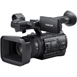
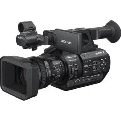
PXW-Z280V/PXW-Z280T

2
Overview
Location and Function of Parts ............................................... 7
Main unit ........................................................................ 7
Screen Display ......................................................................... 12
LCD/viewfinder screen ................................................ 12
Status screen ................................................................. 14
Preparation
Power Supply ........................................................................... 19
Using a battery pack ..................................................... 19
Using AC power ........................................................... 20
Turning the camcorder on/off ...................................... 20
Setting the Clock ..................................................................... 21
Attaching Devices .................................................................... 21
Attaching the lens hood ................................................ 21
Attaching the large eyecup ........................................... 21
Adjusting the Screens ............................................................. 22
Adjusting the LCD screen ............................................ 22
Adjusting the viewfinder .............................................. 22
Adjusting the brightness of the LCD/viewfinder
screen using an assignable button .......................... 22
Using SxS Memory Cards ...................................................... 23
About SxS memory cards ............................................. 23
Inserting SxS memory cards ........................................ 23
Removing an SxS memory card ................................... 23
Switching between SxS memory cards ........................ 23
Formatting (initializing) an SxS memory card ............. 23
Checking the remaining recording time ....................... 24
Restoring an SxS memory card .................................... 24
Using Other Media .................................................................. 25
XQD memory cards ..................................................... 25
SD cards ....................................................................... 26
Table of Contents

3
Shooting
Basic Operation Procedure .................................................... 27
Shooting ....................................................................... 27
Adjusting the zoom ...................................................... 28
Adjusting the focus ...................................................... 29
Monitoring audio while shooting ................................. 30
Changing Basic Settings ......................................................... 30
Video format ................................................................ 30
Adjusting the brightness ............................................... 31
Adjusting for natural colors (white balance) ................ 32
Setting the audio to record ........................................... 34
Image stabilization ....................................................... 36
Time data ...................................................................... 36
Useful Functions ...................................................................... 37
Direct menu operation .................................................. 37
Face detection AF ........................................................ 37
Color bars/reference audio tone ................................... 39
Shot marks .................................................................... 39
OK/NG/KEEP flags (exFAT, UDF) ............................ 39
Reviewing a recording (Rec Review) .......................... 39
Assignable buttons ....................................................... 40
Interval recording (Interval Rec) .................................. 40
Continuous recording (Clip Continuous Rec)
(exFAT, UDF) ....................................................... 41
Picture cache recording (Picture Cache Rec) ............... 42
Slow & Quick Motion .................................................. 43
Simultaneous recording in 2 slots (Simul Rec) ............ 44
4K & HD (Sub) recording ............................................ 44
High dynamic range (HDR) recording ......................... 45
Adjusting the flange focal length automatically .......... 45
Saving and loading configuration data ......................... 46
Planning metadata ........................................................ 49
Acquiring location information (GPS) ......................... 51
Proxy Recording ..................................................................... 52
Supported SD cards ...................................................... 52
Formatting (initializing) SD cards ............................... 52
Checking the remaining capacity ................................. 52
Proxy recording (Proxy Rec) ....................................... 52
Changing proxy recording settings .............................. 53
About the recorded file ................................................. 53
Storage destination of the recorded file ....................... 53
About the file name ...................................................... 53
Recording proxy data only ........................................... 53

4
Connecting to Other Devices via LAN .................................. 54
Connecting using wireless LAN access point mode .... 54
Connecting using wireless LAN station mode ............. 55
Connecting to a device using a LAN cable .................. 57
Connecting to the Internet ..................................................... 59
Connecting using a modem .......................................... 59
Connecting using wireless LAN station mode (Wi-Fi
station mode) .......................................................... 59
Connecting using a LAN cable .................................... 60
List of functions for network connections ................... 61
Uploading a File ...................................................................... 62
Preparations .................................................................. 62
Selecting a file and uploading ...................................... 62
Uploading proxy files automatically ............................ 64
Uploading using Secure FTP ....................................... 64
Transmitting Streaming Video and Audio ........................... 64
Starting streaming ........................................................ 65
Stopping streaming ....................................................... 65
Network client mode .................................................... 66
Using Web Remote Control ................................................... 68
Web Remote Control Menu ................................................... 69
Video monitoring settings (Monitoring Settings) ........ 69
File transfer settings (Upload Settings) ........................ 70
File transfer management (File Transfer) .................... 70
Thumbnail Screen
Configuration of the Thumbnail Screen ............................... 72
Playing Clips ............................................................................ 73
Playing recorded clips .................................................. 73
Playing the selected and subsequent clips in
sequence ................................................................. 73
Adding shot marks during playback (exFAT, UDF) ... 73
Monitoring audio during playback ............................... 73
Clip Operations ....................................................................... 74
Thumbnail menu operations ......................................... 74
Displaying clip properties ............................................ 75
Protecting clips (exFAT, UDF) .................................... 76
Copying clips ............................................................... 76
Deleting clips ............................................................... 77
Adding/deleting clip flags (exFAT, UDF) ................... 77
Filtering the clips displayed using the filtered clip
thumbnail screen (exFAT, UDF) ........................... 77
Deleting shot marks (exFAT, UDF) ............................. 78

5
Filtering clips (frames) using the essence mark
thumbnail screen (exFAT, UDF) ........................... 78
Changing the information displayed on the thumbnail
screen ..................................................................... 78
Changing the index picture of a clip ............................ 78
External Device Connection
Connecting External Monitors and Recording Devices ...... 79
External Synchronization ....................................................... 80
Managing/Editing Clips on a Computer ............................... 81
Connecting using a USB cable ..................................... 81
Connecting an external HDD/USB media ................... 82
Menu Display and Settings
Setup Menu Configuration and Hierarchy .......................... 84
Setup menu hierarchy ................................................... 84
Setup Menu Operations .......................................................... 86
Editing the User menu .................................................. 88
Setup Menu List ...................................................................... 90
User menu .................................................................... 90
Edit User Menu menu .................................................. 90
Camera menu ............................................................... 91
Paint menu .................................................................... 94
Audio menu ................................................................ 101
Video menu ................................................................ 102
LCD/VF menu ............................................................ 103
TC/UB menu .............................................................. 107
Recording menu ......................................................... 107
Thumbnail menu list .................................................. 109
Media menu ................................................................ 110
File menu .................................................................... 112
Network menu ............................................................ 113
System menu .............................................................. 118
Appendix
Important Notes on Operation ............................................ 124
Using your camcorder abroad .................................... 124
Video Formats ....................................................................... 130
About recording media ............................................... 130
Special recording modes and compatible formats ..... 131
Maximum recording time for a clip ........................... 131

6
Output Formats and Limitations ........................................ 132
Video formats and output signals ............................... 132
Network and video output combinations ................... 136
Limitations between recording functions ................... 136
Troubleshooting .................................................................... 137
Power supply .............................................................. 137
Recording/playback .................................................... 137
External devices ......................................................... 138
Wireless LAN connection .......................................... 138
Internet connection ..................................................... 138
ND filter dial .............................................................. 139
Error/Warning Indications .................................................. 140
Error indications ......................................................... 140
Warning indications ................................................... 140
Caution and operation messages ................................ 141
Block Diagrams ..................................................................... 143
Specifications ......................................................................... 146
General ....................................................................... 146
Lens ............................................................................ 147
Camera ....................................................................... 148
Wireless LAN ............................................................. 148
Inputs/outputs ............................................................. 148
Display ....................................................................... 149
Internal microphone ................................................... 149
Media slots ................................................................. 149
Supplied accessories ................................................... 149
Index ....................................................................................... 152
7
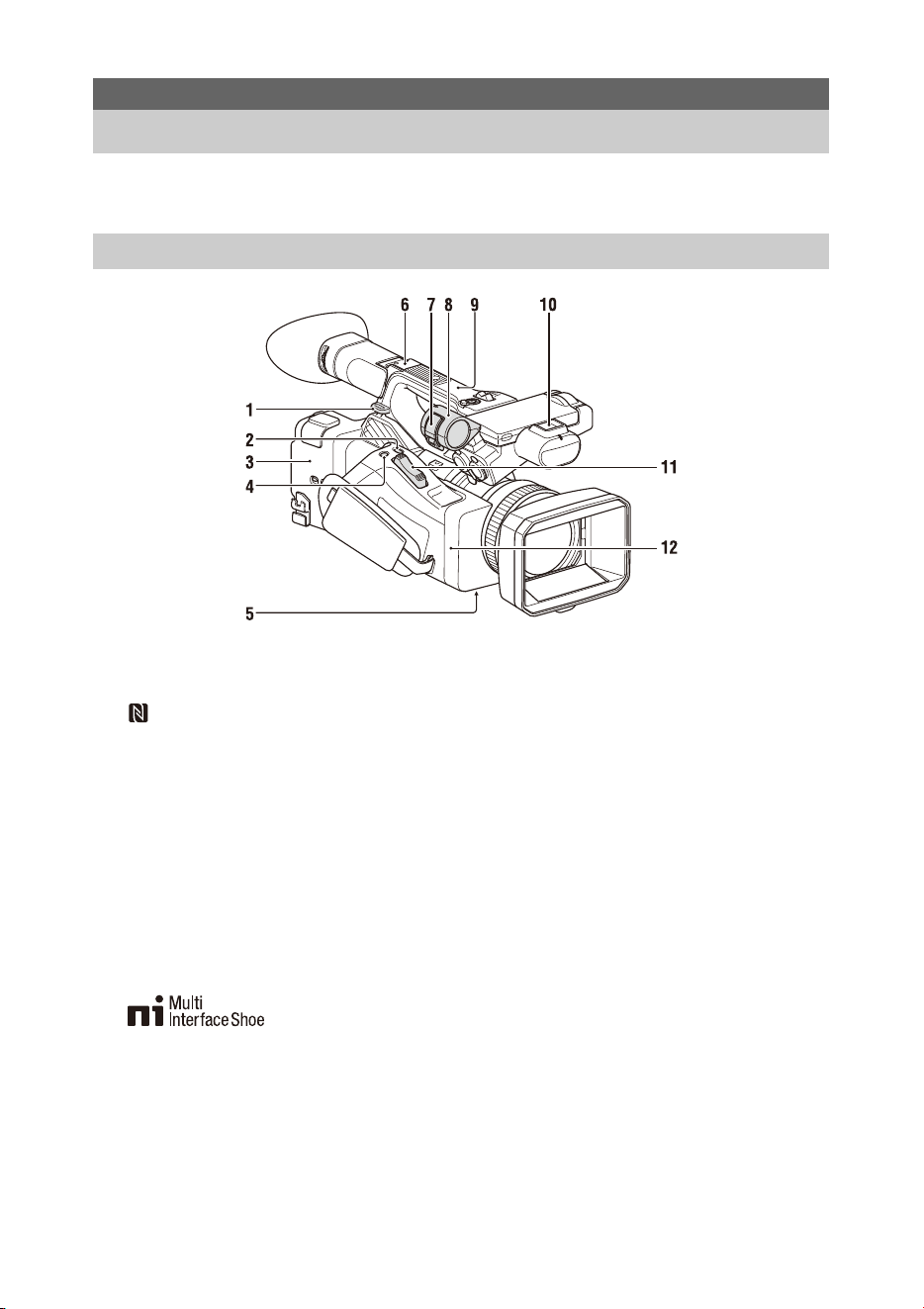
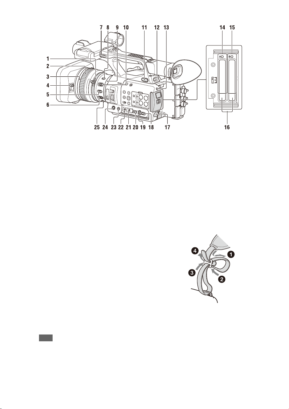
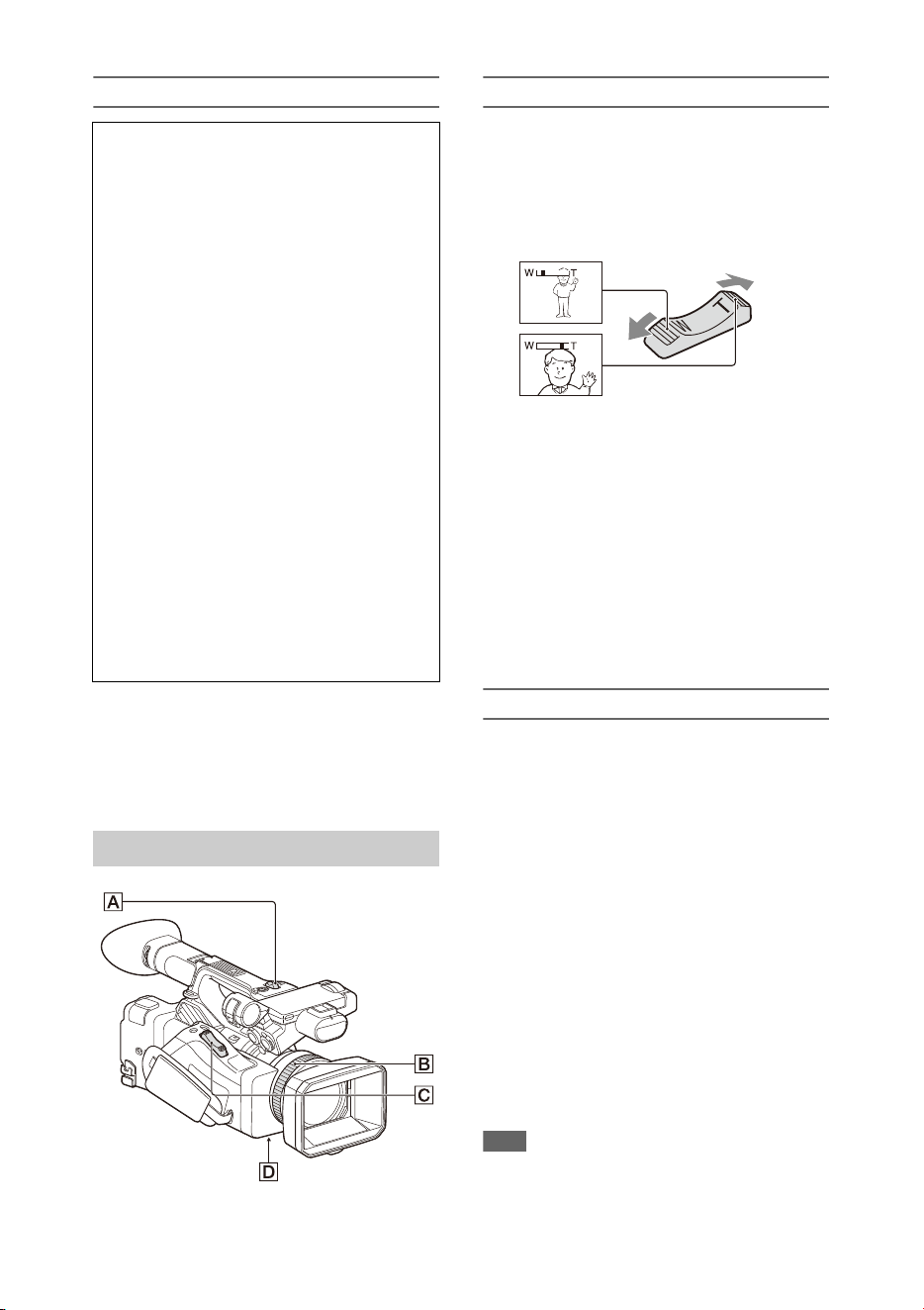
For details about the usage and function of each part, see the referenced page.
1. Hook for shoulder strap (10)
2. ASSIGN7/DIRECT MENU button (40)
3. (N mark)
• Hold an NFC-compatible smartphone near
this mark to establish a wireless connection
between the camcorder and smartphone.
For details, refer to the operating
instructions of the smartphone.
• NFC (Near Field Communication) is an
international standard for short-range radio
communication.
4. ASSIGN8/FOCUS MAG button
5. ZOOM switch (bottom) (28)
6. Multi Interface Shoe (rear)
For details about accessories supported by the
Multi Interface Shoe, contact your sales
representative.
7. Microphone clamper
8. Microphone holder (35)
9. GPS antenna
10. Multi Interface Shoe (front)
11. Power zoom lever (28)
12. Wi-Fi antenna
Overview
Location and Function of Parts
Main unit
8
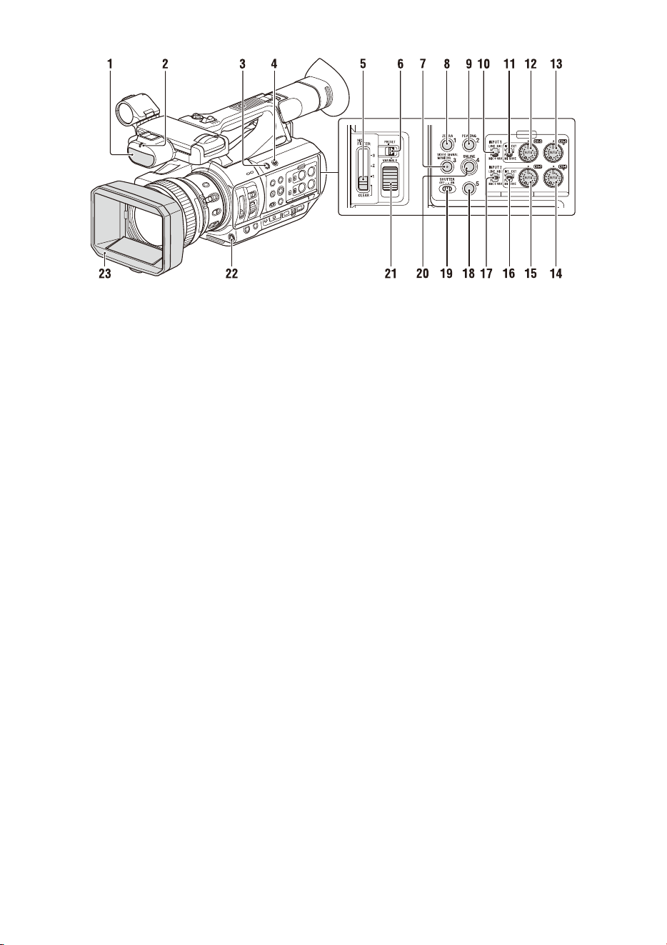
1. Internal microphone (34)
2. Recording/tally lamp (front) (122)
Flashes when the remaining capacity on the
recording media or battery is low.
3. ASSIGN6 button
4. FULL AUTO button (27)
5. ND FILTER switch
6. ND FILTER mode switch
7. ASSIGN3/VIDEO SIGNAL MONITOR
button
8. ASSIGN1/ZEBRA button
9. ASSIGN2/PEAKING button
10. INPUT1 switch (34)
11. CH1 (INT/EXT/MI SHOE) switch (34)
12. AUDIO LEVEL (CH1) dial (34)
13. AUDIO LEVEL (CH3) dial
14. AUDIO LEVEL (CH4) dial
15. AUDIO LEVEL (CH2) dial
16. CH2 (INT/EXT/MI SHOE) switch
17. INPUT2 switch (34)
18. ASSIGN5 button
19. SHUTTER switch
20. ASSIGN4/ONLINE button
21. ND control dial
22. WB SET button
23. Lens hood with lens cover (21)
9
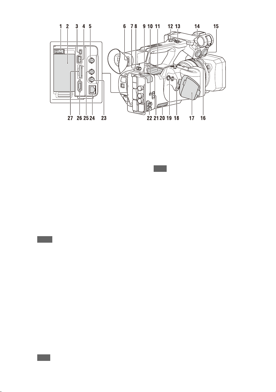
1. BATT RELEASE button (19)
2. Battery pack attachment (19)
3. Multi/Micro USB connector (81)
4. USB3.0 (HOST) connector (type A)
5. SDI OUT connector (79)
6. Diopter adjustment dial (22)
7. ON/STANDBY switch (20)
?: ON
1: STANDBY
8. Power lamp
9. USB2.0 (HOST) connector (type A) (59)
10. IN/OUT (input/output selector) switch
11. Air outlet
Notes
• Areas around the air outlet may become hot.
• Do not cover the air outlet.
12. Handle zoom lever (28)
13. Handle record button
When the lever is set to the HOLD position, the
handle record button is not operable.
14. AUDIO INPUT1 connector (34)
15. AUDIO INPUT2 connector (34)
16. Cable holder
Provided for securing a microphone cable, etc.
17. Grip belt
18. Multi selector (V/v/B/b/SET button)
19. Record button (27)
20. Air inlet
Note
• Do not cover the air inlet.
21. REMOTE connector
The REMOTE connector is used for controlling
start/stop of recording and other functions on the
video device and peripherals connected to it.
22. Cable clamper
Note
• Do not use for any purpose other than securing
cables.
23. GENLOCK IN/VIDEO OUT connector
24. Wired LAN connector
25. TC IN/OUT connector
26. HDMI OUT connector (79)
27. UTILITY SD/MS slot/access lamp
Used for proxy recording and storing/loading
settings (File function). To be supported by a
future upgrade (software update).
10
1. Zoom ring (29)
2. Focus ring (29)
3. Full MF switch (29)
Switch manual focus mode on/off by moving
the focus ring forward/back.
4. Lens cover lever (21)
Opens/closes the lens cover.
5. MACRO switch (29)
6. FOCUS switch (29)
7. Hook for shoulder strap
8. STEADY SHOT button (36)
9. Iris ring (31)
10. IRIS switch (31)
11. i (headphone) jack
For stereo mini-jack headphones.
12. Recording/tally lamp (rear) (122)
Flashes when the remaining capacity on the
recording media or battery is low.
13. SLOT SELECT button
14. SxS memory card A slot/access lamp (23)
15. SxS memory card B slot/access lamp (23)
16. EJECT button
When pressed, the EJECT button pops out.
Press again to remove a card.
Note
• Pressing the EJECT button during recording will
stop the recording.
17. DC IN connector
18. CANCEL/BACK button (86)
19. SEL/SET dial (86)
20. MENU button (86)
Button has a raised tactile bar for your
convenience in locating the button.
21. WHT BAL switch (33)
22. GAIN switch (31)
23. ASSIGN10/IRIS PUSH AUTO button
24. ASSIGN9 button
25. FOCUS PUSH AUTO button (29)
To attach a shoulder strap
Attach a shoulder strap to the hooks for the
shoulder strap.
11
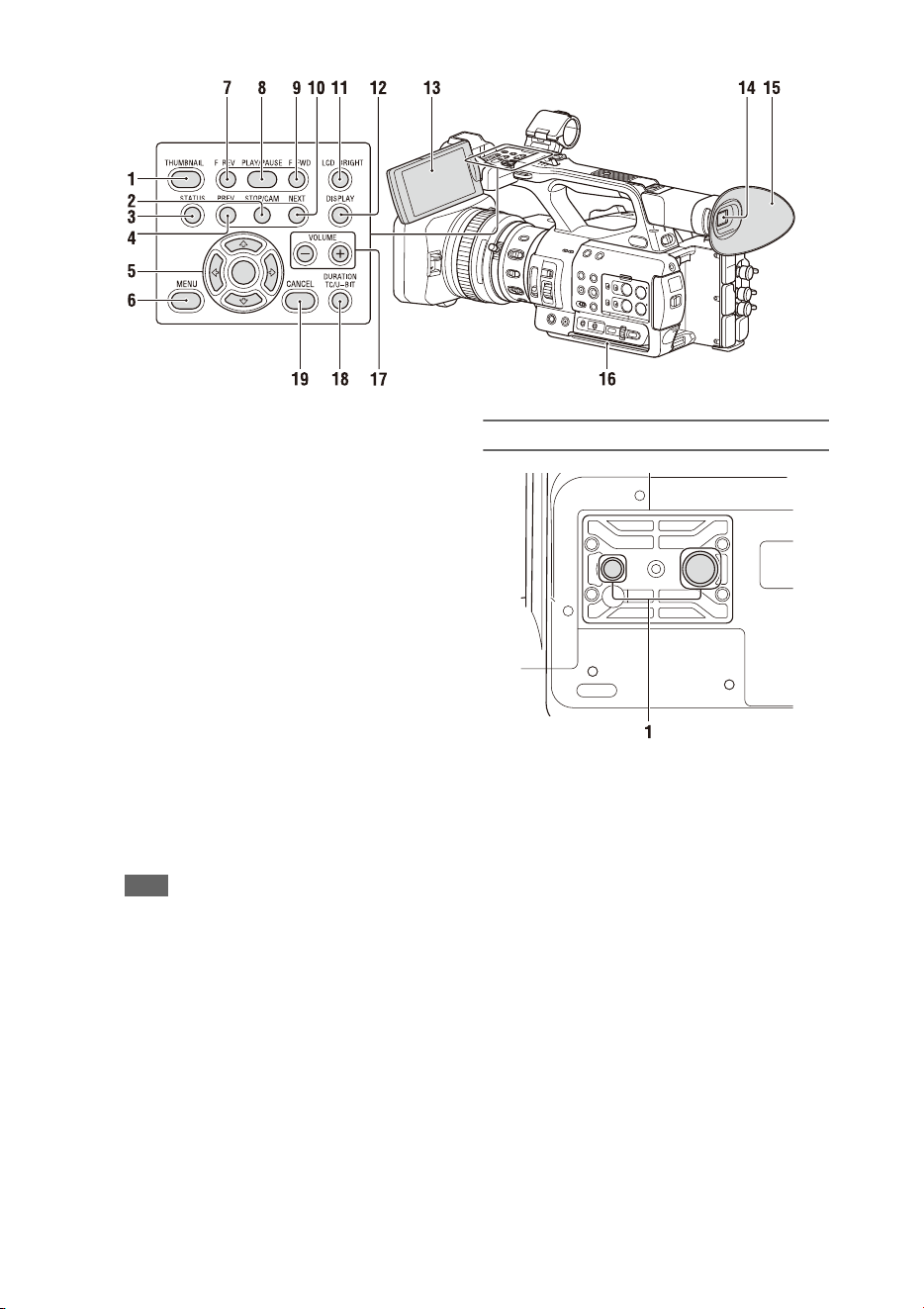
1. THUMBNAIL button (72)
2. STOP button (73)
3. STATUS CHECK button (14)
4. PREV button (73)
5. V/v/B/b/SET button (86)
6. MENU button (86)
7. F REV button (73)
8. PLAY/PAUSE button (73)
9. F FWD button (73)
10. NEXT button (73)
11. LCD BRIGHT button (22)
12. DISPLAY button (12)
13. LCD screen (22)
14. Viewfinder (22)
15. Large eyecup
16. Air inlet
Note
• Do not cover the air inlet.
17. VOLUME buttons (30)
18. DURATION/TC/U-BIT button (36)
19. CANCEL button (86)
Bottom Side
1. Tripod screw holes (1/4 inch, 3/8 inch)
Compatible with 1/4-20UNC screws and 3/8-
16UNC screws.
Attach to a tripod (sold separately, screw length
of 5.5 mm or less).
12
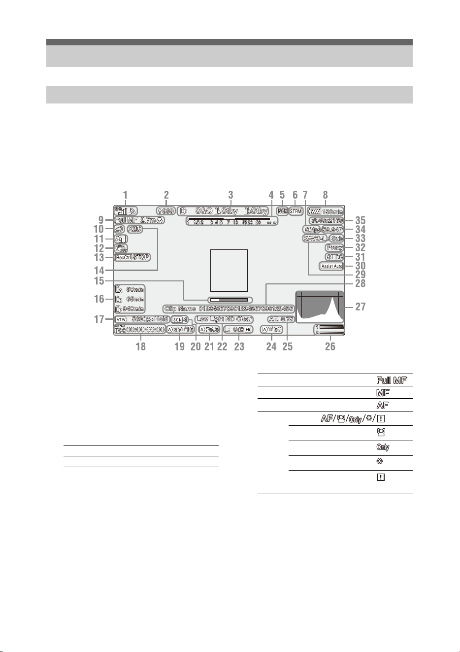
While recording, standing by to record, or during playback, the statuses and settings of the camcorder are
superimposed on the LCD/viewfinder screen.
You can show/hide the information using the DISPLAY button.
You can also select to show/hide each item independently (page 105).
1. Network status indicator (page 13)
Displays the status of the network connection as
an icon.
2. Uploading/Number of files to transfer
indicator
3. Recording mode/slot A/B operation status
indicator
4. Depth-of-field indicator
5. Network client mode status indicator
Displays the connection status in network client
mode.
6. Streaming status indicator
7. Slow & Quick Motion shooting frame rate
indicator
8. Remaining battery capacity/DC IN
voltage indicator
9. Focus mode indicator (page 37)
a) Displayed when there is no registered face and no
faces are detected, and when there is a registered
face but it is not detected.
10. Zoom position indicator
Displays zoom position in the range of 0 (wide
angle) to 99 (telephoto).
11. GPS status indicator
12. Image stabilization mode (SteadyShot)
indicator
Screen Display
LCD/viewfinder screen
Information displayed on the screen while shooting
zRec Recording
Stby Recording standby
FULL MF mode
MF mode
AF mode
Face detection AF ( )
Face detection icon
Face only AF icon
Registered face icon
Face Only AF mode auto
focus paused icon
a)
13
13. SDI output/HDMI output Rec Control
indicator
Displayed when Display On/Off >SDI/HDMI
Rec Control in the LCD/VF menu and SDI/
HDMI Rec Control >Setting in the Video menu
are both set to On.
14. Digital extender indicator
15. Focus assist indicator
16. Media remaining capacity indicator
17. White balance mode indicator
18. Timecode indicator (page 36)
19. ND filter indicator (page 32)
20. Scene file indicator (page 46)
21. Iris position indicator
22. Video level warning indicator
23. Gain indicator (page 31)
24. Shutter mode/shutter speed indicator
25. AE mode/AE level indicator
26. Audio level meter
27. VIDEO SIGNAL MONITOR display
(waveform monitor/vectorscope/
histogram)
28. Clip name indicator
29. Recording format (codec) indicator
(page 118)
Displays the format that is recorded on an SxS
memory card.
30. Gamma display assist indicator
31. Gamma indicator (page 96)
Displays the gamma setting.
32. Proxy status indicator
33. 4K & HD (Sub) recording indicator
34. System frequency and scan method
indicator
35. Recording format (picture size) indicator
(page 118)
Displays the picture size that is recorded on an
SxS memory card.
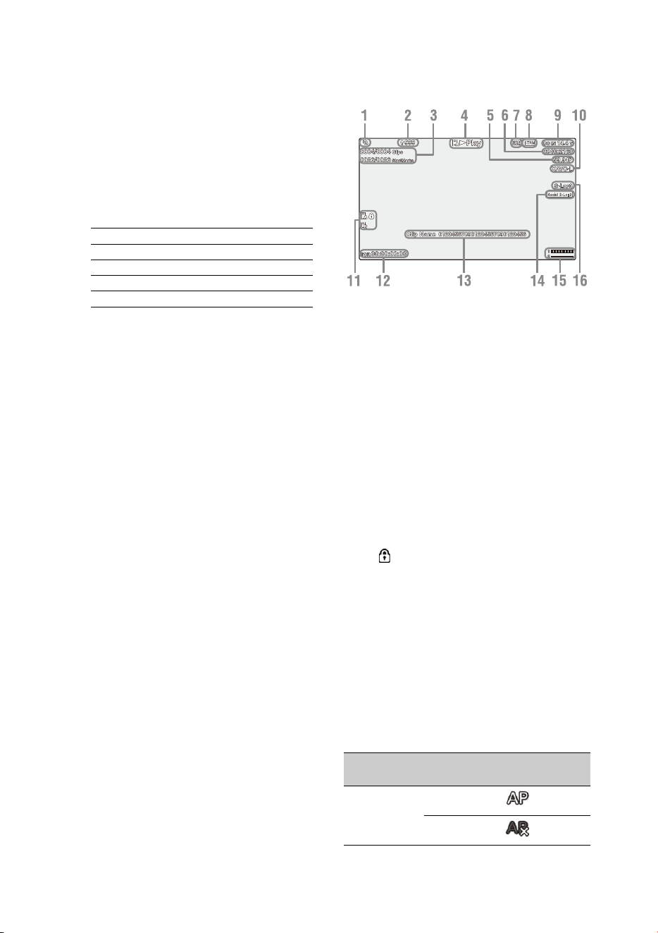
Information displayed on the playback screen
The following information is superimposed on
the playback picture.
1. Network status indicator
2. Uploading/Number of files to transfer
indicator
3. Clip number/Total number of clips
4. Playback mode indicator
5. Playback format (frame rate) indicator
6. Playback format (picture size) indicator
7. Network client mode status indicator
8. Streaming status indicator
9. Remaining battery capacity/DC IN
voltage indicator
10. Playback format (codec) indicator
11. Media indicator
A mark appears to the left if the memory
card is write-protected.
12. Time data indicator
The time data is displayed when Display On/Off
>Timecode in the LCD/VF menu is set to On
and the DISPLAY button is pressed.
13. Clip name indicator
14. Gamma display assist indicator
15. Audio level meter
16. Gamma indicator
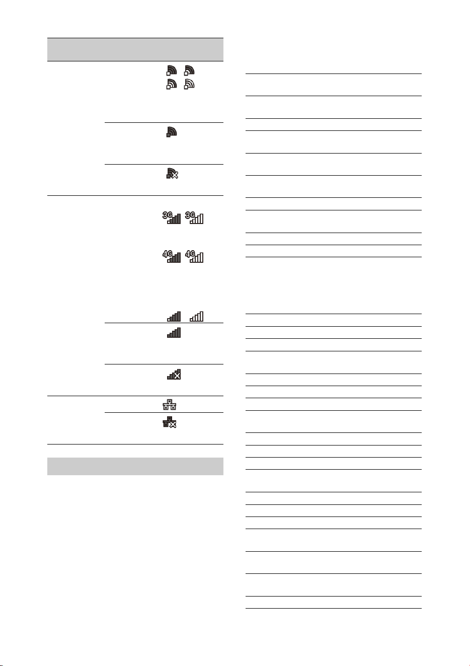
Network connection icon indicators
ATW Automatic mode
ATW Hold Pause automatic mode
W:P Preset mode
W:A Memory A mode
W:B Memory B mode
Network
mode
Connection
status
Icon
Access point
mode
Operating as an
access point
Access point
operation error
14
You can check the settings and status of the
camcorder on the status screen.
Status screen operations
To display the status screen:
• Push the STATUS CHECK button.
To switch the status screen:
• Turn the SEL/SET dial or press the V/v button.
To hide the status screen:
• Push the STATUS CHECK button.
Camera Status screen
Displays the picture quality, zoom settings, and
status.
Audio Status screen
Displays the input setting, audio level meter, and
wind noise reduction filter setting for each
channel.
Station mode Wi-Fi
connected
Wi-Fi signal
strength (4
levels)
Wi-Fi
disconnected
(incl. during
setup)
Wi-Fi
connection
error
Modem 3G/4G signal
strength (5
levels)
3 levels for
modems
without signal
strength
detection
3G connected
–
4G connected
–
Network
connection (3G/
4G indeterminate)
–
3G/4G
disconnected
(incl. during
setup)
3G/4G
connection
error
Wired LAN LAN connected
LAN
connection
error
Status screen
Network
mode
Connection
status
Icon
White Switch<B> White balance memory B
adjustment value
White Switch<A> White balance memory A
adjustment value
White Switch<P> Preset White setting
ND<Preset> Preset1 to 3 setting for ND
Filter
Zebra1 Zebra1 On/Off setting and
level
Zebra2 Zebra2 On/Off setting and
level
Gamma Gamma category and curve
Gain Switch Gain<L>, Gain<M>,
Gain<H> setting
Handle Zoom Speed Handle Zoom setting
Scene File Current scene file and file ID
CH1 level meter CH1 level meter
CH1 Input Source CH1 input source
CH1 Ref./Sens. CH1 input reference level
CH1 Wind Filter CH1 microphone wind
reduction filter setting
CH2 level meter CH2 level meter
CH2 Input Source CH2 input source
CH2 Ref./Sens. CH2 input reference level
CH2 Wind Filter CH2 microphone wind
reduction filter setting
CH3 level meter CH3 level meter
CH3 Input Source CH3 input source
CH3 Ref./Sens. CH3 input reference level
CH3 Wind Filter CH3 microphone wind
reduction filter setting
CH4 level meter CH4 level meter
CH4 Input Source CH4 input source
CH4 Ref./Sens. CH4 input reference level
CH4 Wind Filter CH4 microphone wind
reduction filter setting
HDMI Output CH HDMI output audio channel
combination setting
Analog Output CH Analog output audio channel
combination setting
Monitor CH Monitor channel setting

15
System Status screen
Displays the video signal settings.
Video Output Status screen
Displays the SDI, HDMI, and video output
settings.
Assignable Button Status screen
Displays the functions assigned to each of the
assignable buttons.
Battery Status screen
Displays information about the battery and DC IN
source.
Media Status screen
Displays the remaining space, available recording
time, and estimated service life of the recording
media (SxS memory card A/SxS memory card B)
and UTILITY media.
Headphone Out Headphone output type
setting
Frequency/Scan System frequency and
scanning method settings
File System File system setting
Codec Codec setting
Simul Rec 2-slot Simul Rec On/Off
status
Title Prefix Clip name title prefix
Picture Size Recording format picture size
Rec Function Enabled special recording
format and settings
Clip Continuous Rec Clip Continuous Rec On/Off
status
Picture Cache Rec Picture Cache Rec On/Off
status and setting
Number Clip name numeric suffix
Shooting Mode Shooting mode setting
4K & HD (Sub) Rec 4K & HD (Sub) recording
function On/Off status
Proxy Rec Proxy recording On/Off
status and setting
Genlock Genlock status
SDI Output picture size
Rec Control status
Output On/Off
HDMI Output picture size
Rec Control status
Output On/Off
VIDEO Output picture size
Output On/Off
Gamma Gamma setting
Color Gamut Color gamut setting
Gamma Display Assist Gamma display assist setting
1 Function assigned to the
Assign 1 button
2 Function assigned to the
Assign 2 button
3 Function assigned to the
Assign 3 button
4 Function assigned to the
Assign 4 button
5 Function assigned to the
Assign 5 button
6 Function assigned to the
Assign 6 button
7 Function assigned to the
Assign 7 button
8 Function assigned to the
Assign 8 button
9 Function assigned to the
Assign 9 button
10 Function assigned to the
Assign 10 button
Detected Battery Battery type
Remaining Remaining capacity (%)
Charge Count Number of recharges
Capacity Remaining capacity (Ah)
Voltage Voltage (V)
Manufacture Date Date of battery manufacture
Video Light Remaining Remaining charge level of the
video light battery
Power Source Power supply source
Supplied Voltage Supplied power source
voltage
Media A information Displays the media icon
when recording media is
inserted in slot A.
Media A protection Displays the lock icon when
the recording media inserted
in slot A is protected
(locked).
Media A remaining
capacity meter
Displays the remaining
capacity of recording media
inserted in slot A expressed
as a percentage on a bar
graph.
16
Rec Button Settings Status screen
Displays the setting status of the record button
and handle record button.
GPS Status screen
Displays the GPS positioning status and
information.
Network Status screen
Displays the connection status of the network
connection.
Wireless LAN settings
Media A remaining
recording time
Displays an estimate of the
remaining recording time of
the recording media inserted
in slot A in units of minutes
under the current recording
conditions.
Remaining life of media
A
Displays the remaining life in
percent (%) of the media
inserted in slot A if the media
stores remaining life data
Media B information Displays the media icon
when recording media is
inserted in slot B.
Media B protection Displays the lock icon when
the recording media inserted
in slot B is protected
(locked).
Media B remaining
capacity meter
Displays the remaining
capacity of recording media
inserted in slot B expressed
as a percentage on a bar
graph.
Media B remaining
recording time
Displays an estimate of the
remaining recording time of
the recording media inserted
in slot B in units of minutes
under the current recording
conditions.
Remaining life of media
B
Displays the remaining life in
percent (%) of the media
inserted in slot B if the media
stores remaining life data
UTILITY media
information
Displays the media icon
when media is inserted in the
UTILITY SD/MS slot.
UTILITY media
protection
Displays the lock icon when
the media inserted in the
UTILITY SD/MS slot is
protected (locked).
UTILITY media
remaining capacity
meter
Displays the remaining
capacity of media inserted in
the UTILITY SD/MS slot
expressed as a percentage on
a bar graph.
UTILITY media
remaining capacity
Displays an estimate of the
remaining recording time of
the recording media inserted
in the UTILITY SD/MS slot
in units of minutes. Or
displays the remaining
capacity in units of GB.
Rec Button Displays the recording target
slot of the record button
Handle Rec Button Displays the recording target
slot of the handle record
button
GPS GPS signal positioning status
Dilution of Precision Position information
precision
Latitude Latitude information
Longitude Longitude information
Altitude Altitude information
Positioning date and
time
Positioning date and time
Current date and time Current date and time
Time Zone Time zone setting
Wireless LAN Wireless network settings,
connection status
Wired LAN Wired LAN network settings,
connection status
Modem Wireless network settings,
connection status using
modem (sold separately)
Setting
display
Status
display
Description
Off --- Wireless LAN
setting is off.
Access Point
Mode
Non Active Not operating as an
access point.
Displayed when
Wi-Fi chip fails.
Active Operating as an
access point.
17
Wired LAN settings
Modem settings
NCM/Streaming Status screen
Displays the connection status and streaming
status in network client mode.
Network Client Mode Status settings
Station Mode Non Active Not operating in
station mode.
Displayed when
Wi-Fi chip fails.
Searching Attempting to
connect to the
previously
connected network
(access point).
Disconnected Not connected to a
network (access
point).
Also displayed
when IP address
was not assigned
using DHCP.
<SSID> Connected to
<SSID> network
(access point).
Setting
display
Status
display
Description
Off --- Wired LAN setting
is off.
On Disconnected Disconnected from
network.
Also displayed
when IP address
was not assigned
using DHCP.
Connected Connected to a
network.
Setting
display
Status
display
Description
Off --- Modem setting is
off.
On Disconnected Not connected to a
network.
Connected Connected to a
network.
Connecting Attempting to
connect to a
network.
No Modem Modem dongle is
not inserted.
Setting
display
Status
display
Description
Network Client Mode
Status
Network client mode status
CCM Name Name of connected CCM in
network client mode
CCM Address Address of connected CCM
in network client mode
Streaming Status Streaming status
Streaming Format Streaming format
information
Streaming Type Type of currently selected
streaming setting
Streaming Destination
Address
Streaming destination
address
Streaming Audio
Channel
Audio channel to
superimpose on streaming
output
Status display Description
Off Network client mode is off.
Connected Network client mode is on,
CCM/XDCAM air is
connected, and control from
CCM/XDCAM air is
enabled.
Connecting Attempting to connect to
CCM/XDCAM air.
Note
If the status does not change
from “Connecting,” the CCM
address setting may be
incorrect. Check that the
address is set correctly.
Destination Address
Error
The host name or IP address
of the CCM to connect may
be incorrect.
Authentication Failed The user name or password
used to connect to the CCM
may be incorrect.
No Network Access Cannot connect to a network.
Check the network
connection status and
settings.
Certificate is not yet
Valid
The CCM certificate is not
valid.
The network date and time
settings may be incorrect.
18
Streaming Status settings
File Transfer Status screen
Displays file transfer information.
Certificate has Expired The period of validity of the
CCM certificate has expired.
The network date and time
settings may be incorrect.
Root Certificate Error The root certificate is invalid.
Note
If this error message is
displayed, contact your Sony
service representative.
Intermediate Cert. Error An intermediate certificate is
invalid.
Note
If this error message is
displayed, contact your Sony
service representative.
Server Certificate Error The server certificate is
invalid.
Note
If this error message is
displayed, contact your Sony
service representative.
Status display Description
Off Streaming is off.
Distributing Streaming is in progress.
Preparing Preparing for streaming.
Destination Address
Error
The host name or IP address
of the streaming destination
may be incorrect.
No Network Access Cannot connect to a network.
Check the network
connection status and
settings.
Auto Upload (Proxy) Auto Upload (Proxy) On/Off
status
Job Status(Remain/
Total)
Number of remaining jobs
and total number of jobs
Total Transfer Progress Transfer progress of total jobs
Auto Upload Server Name of Auto Upload
(Proxy) transfer server
Current File Transfer
Progress
Transfer progress of file
currently being uploaded.
Current Transferring
File Name
Name of file currently being
uploaded.
Server Address Address of file transfer server
Status display Description
Destination Directory Destination directory of file
transfer server
19
You can use a battery pack or AC power supply
from an AC adapter.
When an AC adapter is connected, the AC
adapter has priority even when a battery pack is
attached.
For safety, use only the Sony battery packs and
AC adaptors listed below.
Lithium-ion battery packs
BP-U30 (supplied)
BP-U60
BP-U60T
BP-U90
AC adapters/chargers
BC-U1A (supplied)
BC-U2A
Do not store battery packs in locations exposed to
direct sunlight, flame, or high temperature.
Note
• When operating from a power outlet, use the supplied
AC adapter.
To attach a battery pack, plug the battery pack
into the attachment (page 9) as far as it will go,
and then slide it down to lock it into position.
To remove a battery pack, press and hold the
BATT RELEASE button (page 9), slide the
battery pack up and then pull it out of the
attachment.
Notes
• Before use, charge the battery pack with the BC-U1A
(supplied) or BC-U2A Charger.
• Charging a battery immediately after use while it is
still warm may not fully recharge the battery.
• The BP-U30 cannot be used at the same time as a
modem. To power a modem, use a BP-U60, BP-U60T,
or BP-U90 battery pack.
• The high-capacity BP-U90 Battery Pack is large, and
protrudes from the camcorder when attached. The BP-
U90 is convenient when using the camcorder attached
to a tripod for extended recording periods.
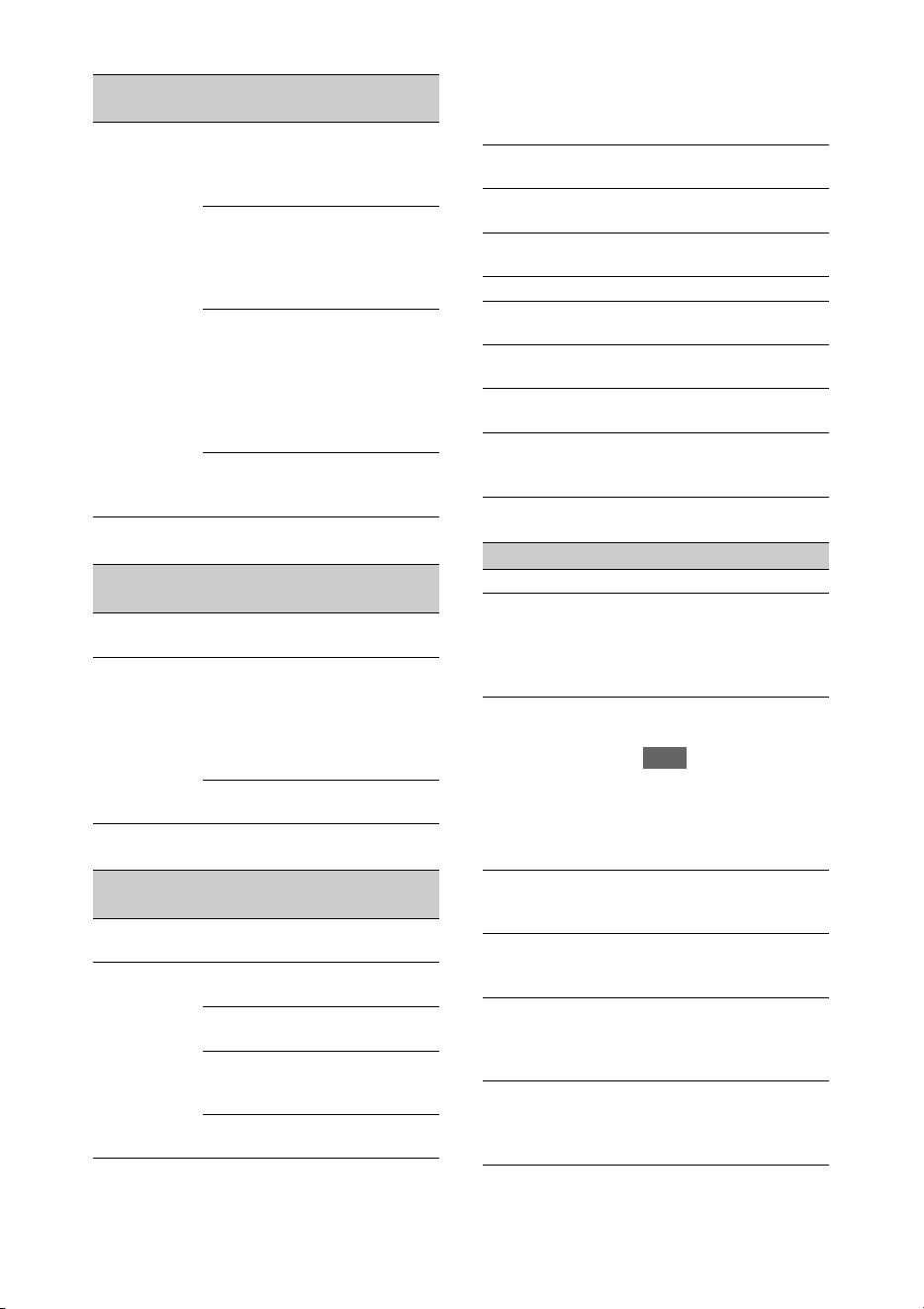
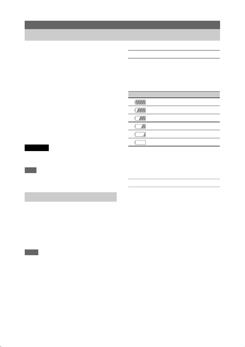
Checking the remaining capacity
When recording or playback is in progress on the
battery pack, an icon to show the current battery
charge level and usage time remaining are
displayed on the LCD/viewfinder screen
(page 12).
The camcorder indicates the remaining usage
time in minutes by calculating the available time
with the battery pack if operation is continued at
the current rate of power consumption.
If the battery pack charge becomes low
If the remaining battery charge falls below a
certain level during operation (Low Battery
state), a low-battery message appears, the
recording/tally lamp starts flashing, and a beep
sound will warn you.
If the remaining battery charge falls below the
level at which operation cannot continue (Battery
Empty state), a battery-empty message appears.
Replace with a charged battery pack.
Changing the warning levels
The Low Battery level is set to 10% of full battery
charge and the Battery Empty level is set to 3% by
factory default. You can change the warning level
settings using Battery Alarm (page 122) in the
System menu.
Preparation
Power Supply
WARNING
Using a battery pack
Icon Remaining capacity
100% to 91%
90% to 71%
70% to 51%
50% to 31%
30% to 11%
10% to 0%
20
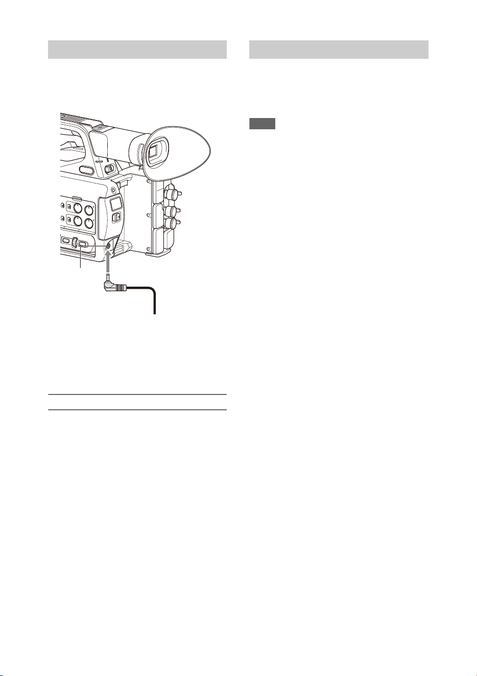
Connecting the camcorder to a power outlet
allows use without worrying about the need to
recharge the battery pack.
1 Connect the power cord (mains lead) to the AC
Adapter.
2 Connect the AC Adapter to the DC IN connector of the
camcorder.
3 Connect the power cord (mains lead) to the wall outlet
(wall socket).
AC adapters
• Do not connect and use an AC adapter in a
confined space, such as between a wall and
furniture.
• If a problem occurs during operation,
immediately disconnect the power cord from
the outlet.
• Do not short-circuit the plug of the AC adapter
with any metallic objects. Doing so will cause a
malfunction.
• You cannot charge the camcorder by
connecting it to the AC Adapter.
To turn the camcorder on, set the ON/STANDBY
switch (page 9) to the ON position ([ ). To turn the
camcorder off, set the ON/STANDBY switch to
the STANDBY position (1).
Notes
• Even when the ON/STANDBY switch is set to the
STANDBY position, the unit continues to draw
standby electric power. Remove the battery pack if not
using your camcorder for an extended period.
• Remove the battery or disconnect the DC IN power
supply after the power lamp is extinguished when the
power switch is set to the STANDBY position. If
power is removed while the switch is in the ON
position, a malfunction of the camcorder or SxS
memory cards may occur.
Using AC power
DC IN
connector
AC adapter plug
Turning the camcorder on/off
21
When you turn the camcorder on for the first time
after purchasing or the backup battery has
completely discharged, the initial setting display
appears on the viewfinder screen and LCD
screen.
Set the date and time of the internal clock using
this screen.
Time Zone
The value shows the time difference from UTC
(Coordinated Universal Time). Change the
setting as required.
Setting the date and time
Move the cursor using the V/v/B/b button
(page 9) or SEL/SET dial (page 10), and press the
SET button or SEL/SET dial to set each item.
Finally, move the cursor to [Finish] and press the
SET button or SEL/SET dial to close the settings
screen and finish setting the clock.
Once the settings screen is closed, you can change
the date, time, and time zone settings using Clock
Set (page 122) in the System menu.
Notes
• If the clock setting is lost because the backup battery
becomes fully discharged due to power being
disconnected for an extended period (no battery pack
and no DC IN power source), the initial settings screen
will be displayed when you next turn the camcorder
on.
• While the initial settings screen is displayed, no other
operation, except turning the power off, is permitted
until you finish the settings on this screen.
• If you do not use your camcorder for about 3 months,
the built-in rechargeable battery gets discharged and
the date and time settings may be cleared from the
memory. In that case, charge the rechargeable battery
and then set the date and time again (page 126).
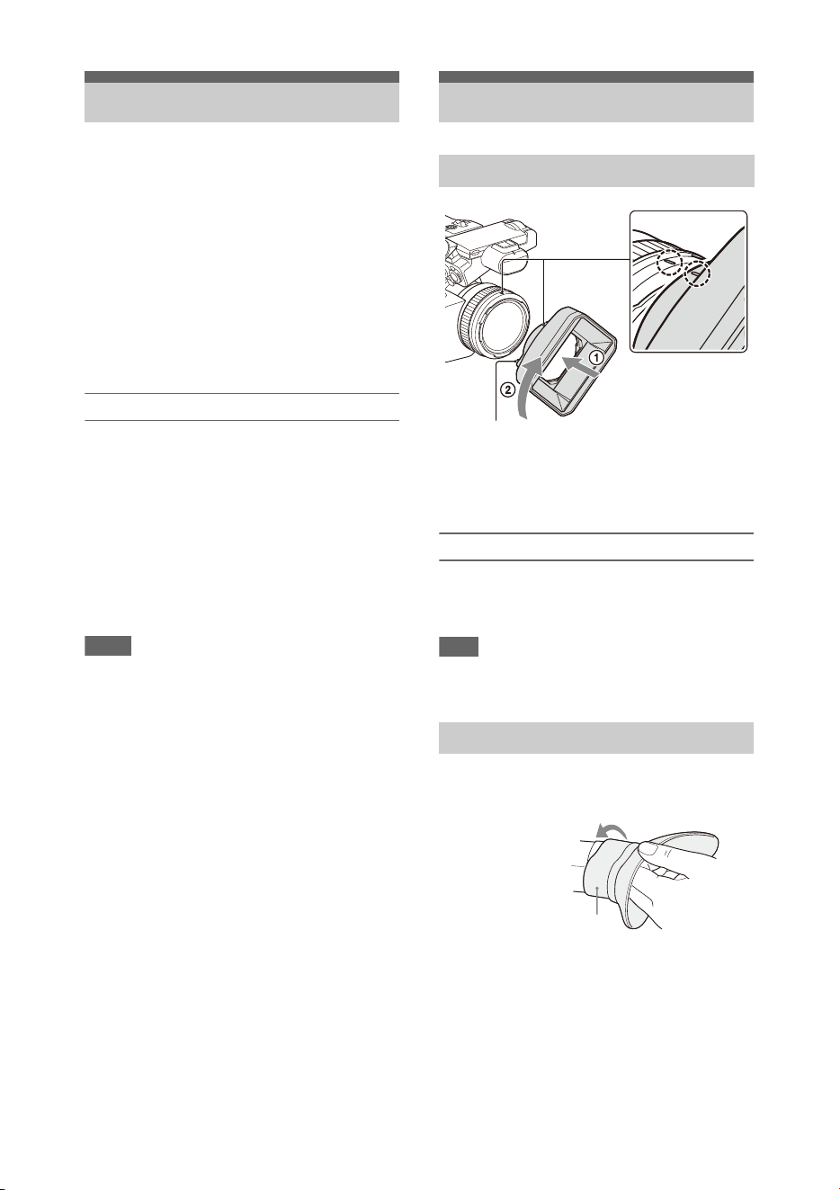
Align the marks on the lens hood to those on
the camcorder, and turn the lens hood in the
direction of the arrow 2 until it is locked.
Removing the lens hood
Turn the lens hood in the opposite direction of the
arrow in the illustration while pressing the PUSH
(lens hood release) button.
Note
• Remove the lens hood when you attach/detach a ø77
mm polarizing filter or protective filter.
Stretch the large eyecup slightly and fit it over the
groove on the viewfinder.
Setting the Clock Attaching Devices
Attaching the lens hood
Attaching the large eyecup
PUSH (lens hood release) button
Large eyecup (supplied)
22
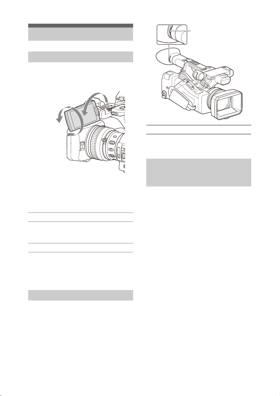
Open the LCD screen 180 degrees (1), then
rotate it to the best angle to record or play back
(2).
You can adjust the angle so that the viewfinder is
facing the subject. Images are displayed as mirror
images on the LCD screen, but are recorded as
normal images.
Adjusting the backlight
Switch the brightness of the backlight using the
LCD BRIGHT button (page 11).
Adjusting the brightness
Adjust the brightness using LCD Setting
>Brightness (page 103) in the LCD/VF menu.
Changes in the brightness do not affect the
brightness of recorded images.
Look through the viewfinder with the LCD screen
closed when using the viewfinder.
If the viewfinder screen display is not clear,
adjust it using the diopter adjustment dial below
the viewfinder.
Adjusting the brightness
Adjust the brightness using VF Setting
>Brightness (page 103) in the LCD/VF menu.
You can display a level bar for adjusting the
brightness of the LCD screen/viewfinder screen
by assigning LCD/VF Adjust to an assignable
button (page 40) beforehand and then pressing
that button.
1 Press the button assigned with LCD/VF
Adjust to display a level bar for
adjusting the brightness.
Each time the button is pressed, the display
switches in sequence between level bar for
the LCD screen t level bar for the
viewfinder t no display.
2 Adjust the level using the V/v/B/b
button or SEL/SET dial, and press the
SET button or SEL/SET dial.
The level bar disappears.
Press the button assigned with LCD/VF
Adjust or do not perform any operation for 3
seconds to hide the level bar.
Adjusting the Screens
Adjusting the LCD screen
Adjusting the viewfinder
2 180
degrees
(max.)
2 90
degrees
(max.)
1 Open 180
degrees
Adjusting the brightness of the
LCD/viewfinder screen using an
assignable button
Diopter adjustment dial
Move it until the picture
becomes clear.

23
This camcorder records audio and video on SxS
memory cards (sold separately) inserted in the
card slots.
Supported memory cards
Use the following Sony SxS memory cards.
Operations are not guaranteed with memory cards
other than the following cards.
SxS PRO+ series
SxS PRO series
SxS-1 series
These cards comply with the ExpressCard
standard.
For details on using SxS memory cards and usage-
related precautions, refer to the instruction manual
for the SxS memory card.
For details about recording media and compatible
formats, see page 130.
Notes
• When recording XAVC-I 3840×2160P, use SxS PRO+
memory cards.
• When recording in XAVC-I recording format or
shooting Slow & Quick Motion with SxS PRO or
SxS-1 memory cards, an unsupported media error may
appear on the screen indicating that normal recording
is not possible. The use of SxS PRO+ memory cards is
recommended.
1 Open the cover of the card slot block.
2 Insert the SxS memory card with the
SxS label facing to the right.
The access lamp (page 10) lights in red, then
changes to green once the memory card is
ready for use.
3 Close the cover.
Note
• The memory card, memory card slot, and image data
on the memory card may be damaged if the card is
forced into the slot in the incorrect orientation.
1 Open the cover of the card slot block,
and press the EJECT button.
The EJECT button pops out.
During recording, this will stop the
recording.
2 Press the EJECT button again to
remove the card.
Notes
• If the camcorder is turned off or the memory card is
removed while the memory card is being accessed, the
integrity of data on the card cannot be guaranteed. All
data recorded on the card may be discarded. Always
make sure the access indicator is green or off before
turning off the camcorder or removing the memory
card.
• An SxS memory card removed from the camcorder
after recording ended may be hot. This is not a
malfunction.
When SxS memory cards are loaded in both card
slots A and B, you can switch the card used for
recording by pressing the SLOT SELECT button
(page 10).
If a card becomes full during recording, the
camcorder automatically switches to the other
card.
Note
• The SLOT SELECT button is disabled during
playback. The memory cards are not switched even if
you press the button. The button is enabled while the
thumbnail screen (page 72) is displayed.
If an SxS memory card is not formatted, or was
formatted in another format, the message
“Unsupported File System” is displayed on the
LCD/viewfinder screen.
Format the card using the following procedure.
Using SxS Memory
Cards
About SxS memory cards
Inserting SxS memory cards
Removing an SxS memory card
Switching between SxS memory
cards
Formatting (initializing) an SxS
memory card

24
Using Format Media (page 110) in the
Media menu, specify Media(A) (slot A) or
Media(B) (slot B), then select Execute.
When a confirmation message appears,
select Execute again.
A message is displayed while formatting is in
progress, and the access indicator is lit red.
When formatting is completed, a completion
message is displayed. Press the SEL/SET dial to
dismiss the message.
If formatting fails
A write-protected SxS memory card or memory
card that cannot be used with this camcorder will
not be formatted.
If a warning message is displayed, replace the
card with an appropriate SxS memory card,
according to the instructions in the message.
Note
• Formatting a memory card erases all data, including
recorded video data and setup files.
While recording (or standing by to record), you
can check the remaining space for the SxS
memory cards loaded in the card slots on the A/B
slot media status/remaining space display of the
LCD/viewfinder screen (page 12).
The remaining recording time is calculated from
the remaining capacity of the media in each slot
and the current video format (recording bit rate),
and is displayed in units of minutes.
Note
• A icon appears if the memory card is write-
protected. If the write-protect switch is switched while
the memory card is inserted, the lock icon will not be
displayed. Always switch the write-protect switch with
the memory card removed.
Replacing an SxS memory card
• If the available time on two cards in total
becomes less than 5 minutes, the warning
message “Media Near Full” is displayed, the
recording/tally lamp flashes, and a beep sound
is output to the headphones to warn you.
Replace with media that has free space.
• If you continue recording until the total
remaining time reaches zero, the message
changes to “Media Full,” and recording stops.
Note
• Up to approximately 600 clips can be recorded on one
SxS memory card.
If the number of recorded clips reaches the limit, an
indication that the maximum number of clips has been
reached is displayed.
If for any reason an error should occur in a
memory card, the card must be restored before
use.
When you load an SxS memory card that needs to
be restored, a message appears on the LCD/
viewfinder screen to ask whether you want to
restore it.
Restoring a card
Select Execute using the V/v /B/b button or
SEL/SET dial, and press the SET button or
SEL/SET dial.
A message and progress status (%) are displayed
while formatting is in progress, and the access
lamp is lit red.
When restoration ends, a completion message
appears.
If restoration fails
• Write protected SxS memory cards and cards on
which memory errors have occurred cannot be
restored. A warning message appears for such
cards. Follow the instructions in the message
and unprotect the card or replace it with another
card.
• SxS memory cards on which memory errors
have occurred may become usable if they are
reformatted.
• In some cases, some clips can be restored while
others cannot. The restored clips can be played
normally.
• If the message “Could not Restore Some Clips”
keeps appearing after repeated attempts at
restoration, it may be possible to restore the SxS
memory card with the following procedure.
1 Use the copy function (page 76) of the camcorder to
copy the required clips to another SxS memory card.
2 Format the unusable SxS memory card on the
camcorder.
3 Copy the required clips back to the newly formatted
SxS memory card.
Checking the remaining recording
time
Restoring an SxS memory card

25
Notes
• For restoration of media recorded with this camcorder,
be sure to use this camcorder.
Media recorded with a device other than this
camcorder or with another camcorder of different
version (even of the same model) may not be restored
using this camcorder.
• Clips shorter than 2 seconds cannot be restored.
By using an optional QDA-EX1 Media Adapter,
you can insert an XQD memory card into an SxS
memory card slot and use it instead of an SxS
memory card for recording and playback.
Compatible XQD cards
S-series XQD memory cards
G-series XQD memory cards
H-series XQD memory cards
N-series XQD memory cards
For details on using a QDA-EX1 Media Adapter,
refer to the instruction manual supplied with it.
For details about recording media and compatible
formats, see page 130.
Notes
• High-speed playback (page 73) may not be properly
achieved with an XQD memory card.
• When recording in high rate formats, such as XAVC-I
recording format or 3840×2160P, an unsupported
media error may appear on the screen indicating that
normal recording is not possible. The use of SxS PRO+
memory cards is recommended.
• Not all XQD memory cards are guaranteed to work
with this camcorder. For compatible memory cards,
contact your dealer.
Formatting (initializing)
XQD memory cards must be formatted the first
time they are used in the camcorder.
An XQD memory card to be used with this
camcorder must be formatted using the format
function of this camcorder. It is also necessary to
format an XQD memory card for use if a caution
message is displayed when you mount the XQD
memory card.
If an XQD memory card that was formatted in a
format unsupported by this camcorder is inserted,
the message “Unsupported File System” is
displayed on the LCD/viewfinder screen.
Format the media as described below.
Using Other Media
XQD memory cards

26
To execute formatting
Using Format Media (page 110) in the
Media menu, specify Media(A) (slot A) or
Media(B) (slot B), then select Execute.
A message is displayed while formatting is in
progress, and the access indicator is lit red.
When formatting ends, a completion message
appears.
Note
• Formatting an XQD memory card erases all data on the
card, including protected video. The data cannot be
restored.
To use media formatted on the camcorder in the
slot of another device
Make a backup of the media, then format it using
the other device.
By using an optional MEAD-SD02, you can
insert an SD card into an SxS memory card slot
and use it instead of an SxS memory card for
recording and playback.
For details about using an MEAD-SD02 Media
Adapter, refer to the instruction manual supplied
with the adapter.
For details about recording media and compatible
formats, see page 130.
Note
• High-speed playback (page 73) may not be properly
achieved with an SD card.
SDXC cards (exFAT only)
(Speed Class: Class 10)
Notes
• Not supported in modes other than exFAT mode.
• Do not use SDXC cards at the same time as other
memory cards. If different types of media are used at
the same time, the camcorder cannot switch cards
when the media becomes full.
• When recording in XAVC-I recording format or
shooting Slow & Quick Motion (page 43), an
unsupported media error may appear on the screen
indicating that normal recording is not possible,
depending on the SDXC cards used. The use of SxS
PRO+ memory cards is recommended.
• SDXC cards recorded using PMW series and PXW
series camcorders may not be supported, depending on
the camcorder model.
For details, contact your Sony dealer or a Sony service
representative.
SDHC cards (FAT only)
(Speed Class: Class 10)
Note
• Not supported in exFAT and UDF modes.
Formatting (initializing)
SD cards must be formatted the first time they are
used in the camcorder.
SD cards for use in the camcorder should be
formatted using the format function of the
camcorder.
If a message appears when the SD card is inserted
into the camcorder, format the SD card.
If an SD memory card that was formatted in a
format unsupported by this camcorder is inserted,
the message “Unsupported File System” is
displayed on the LCD/viewfinder screen.
Format the media as described below.
To execute formatting
Using Format Media (page 110) in the
Media menu, specify Media(A) (slot A) or
Media(B) (slot B), then select Execute.
A message is displayed while formatting is in
progress, and the access indicator is lit red.
When formatting ends, a completion message
appears.
Note
• Formatting an SD card erases all data on the card,
including protected video. The data cannot be restored.
To use media formatted on the camcorder in the
slot of another device
Make a backup of the media, then format it using
the other device.
SD cards

27
Basic shooting is conducted using the following
procedure.
1 Attach the necessary devices, and check
that power is being supplied.
2 Load the memory card(s).
If you load two SxS memory cards in
memory card slots A and B, recording is
continued by automatically switching to the
second card when the first card becomes full.
3 Set the ON/STANDBY switch to the ON
position.
The recording screen is displayed on the
LCD/viewfinder screen.
4 Press the grip or handle record button
(page 9).
The recording/tally lamp lights and recording
begins.
5 To stop recording, press the record
button again.
Recording stops, and the camcorder switches
to STBY (standby) mode.
Shooting (Full Auto Mode)
Press the FULL AUTO button, turning the
button indicator on.
Full Auto mode is turned on, Auto Exposure
(page 92) is activated, and Auto ND Filter, Auto
Iris, AGC (Auto Gain Control), Auto Shutter, and
ATW (Auto Tracing White balance) are set to On.
Then, the brightness and white balance are
automatically adjusted.
When you wish to adjust them manually, turn Full
Auto mode off.
Continuous recording on the memory
cards (Relay Rec)
When memory cards are inserted in both slots A
and B, recording automatically switches to the
second memory card just before the remaining
capacity on the first card is reduced to zero.
You can continue recording continuously when
switching memory cards by replacing the
memory card that is full with a new memory card.
Notes
• Do not eject a memory card while recording to it is in
progress. Remove only the memory card in the slot
whose access lamp is turned off during recording.
• If a recordable memory card is loaded into the other
slot when the remaining time of the memory card that
is recording is less than 1 minute, the message “Will
Switch Slots Soon” is displayed. The message
disappears after switching memory card slots.
• The relay recording function may not work if you start
recording when the remaining time of the memory card
is less than 1 minute. To perform the relay recording
properly, make sure that the remaining time of the
memory card is more than 1 minute.
• Video created using the camcorder relay recording
function cannot be played back seamlessly on the
camcorder.
• To combine video created using the camcorder relay
recording function, use Content Browser software.
Shooting
Basic Operation Procedure
Shooting
28
About clips
To delete a clip
You can delete the last recorded clip using the
Last Clip Delete function (page 121). To delete
all clips or specific clips, perform the operation
from the thumbnail screen (page 77).
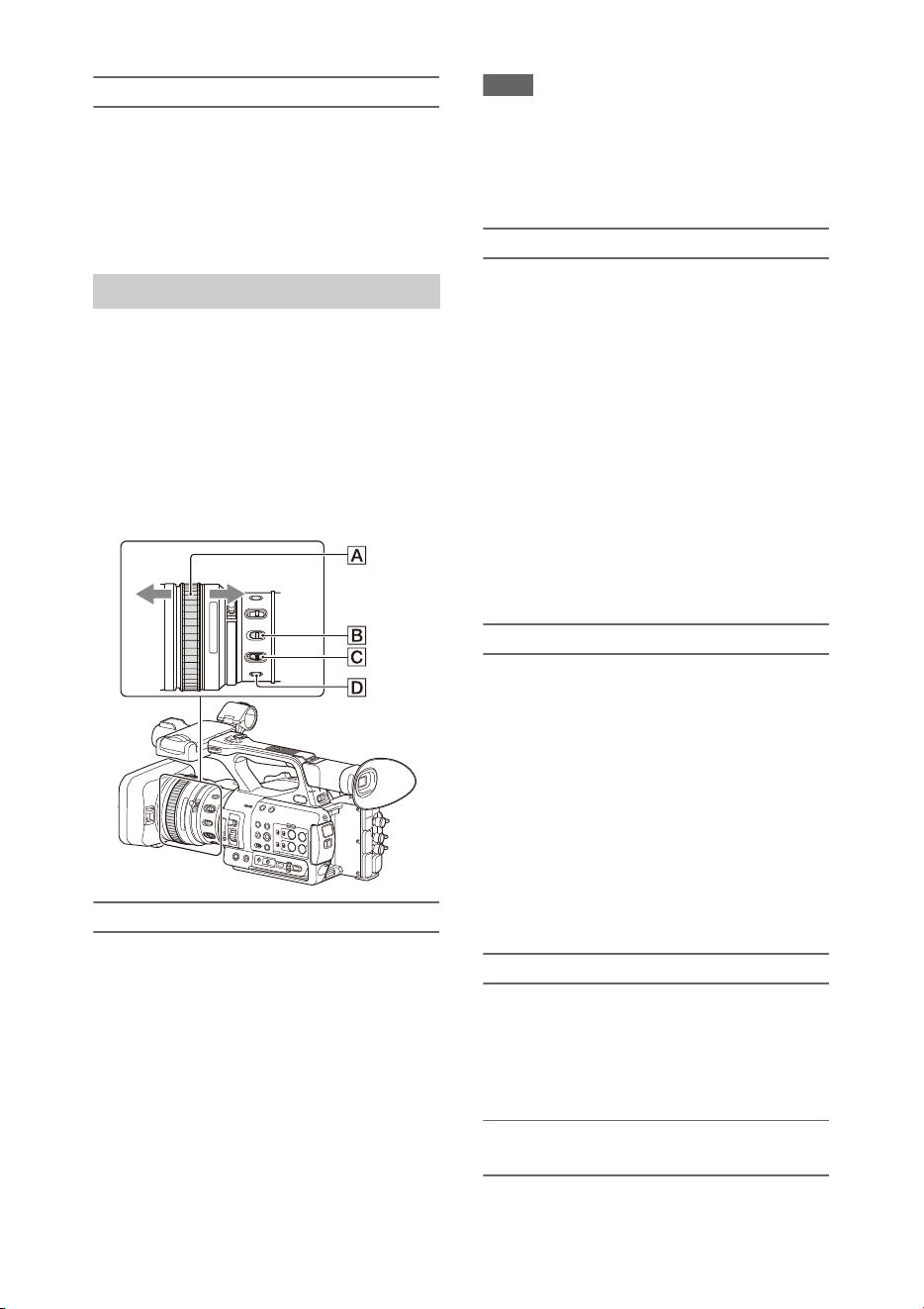
Using the power zoom lever
1. Set the ZOOM switch D to SERVO.
2. Zoom by pressing the power zoom lever C.
Lightly press the power zoom lever C for a
slower zoom. Fully press it for a faster zoom.
• The minimum distance required between your
camcorder and the subject for focus is about 5
cm (about 2 in.) for wide angle and about 80 cm
(about 2 5/8 feet) for telephoto.
• The focus may not be adjusted at certain zoom
positions if the subject is within 80 cm (about 2
5/8 feet) from your camcorder.
• Keep your finger on the power zoom lever C.
If you move your finger off the power zoom
lever C, the operation sound of the power
zoom lever may also be recorded.
Using the handle zoom
1. Set the handle zoom operation to “Low,”
“High,” or “Variable” using Handle Zoom
(page 93) >Setting in the Camera menu.
• When set to “Variable,” you can zoom in or
out at a variable speed according to the
pressure applied to the switch.
• When set to “Low” or “High”, you can
zoom in or out at fixed speed, regardless of
the pressure applied to the switch. You can
set the speed to “Low” or “High” using
Handle Zoom in the Camera menu.
• By assigning the Handle Zoom >Setting
function to an assignable button (page 40),
you can switch the handle zoom operation
each time the button is pressed.
2. Press the handle zoom lever A to zoom in or
out.
Note
• You cannot use the handle zoom lever A when the
handle zoom operation is set to OFF.
Clip (recording data)
When you stop recording, video, audio, and
subsidiary data from the start to end of the
recording are recorded as a single clip on an
SxS memory card.
Clip names
Each clip recorded by the camcorder is
automatically assigned a name using the
naming mode that is set in Clip Naming
(page 111) of the Media menu.
Maximum clip duration
The maximum duration of a clip varies
depending on the recording format.
The maximum duration of continuous
recording is the same as the maximum duration
of a clip. If the recording time exceeds the
maximum duration of a clip, a new clip is
created automatically and recording continues.
The new clip appears as a separate clip on the
thumbnail screen.
For details about the maximum recording time
of a clip for each recording format, see
“Maximum recording time for a clip”
(page 131).
Adjusting the zoom
Wide view: Wide
Close view: Telephoto
29
Using the zoom ring
1. Set the ZOOM switch D to MANUAL.
2. Zoom by turning the zoom ring B.
You can zoom at the desired speed by turning
the zoom ring B. Fine adjustment is also
possible.
Tips for focusing
• Move the power zoom lever towards T
(telephoto) and adjust the focus, then, towards
W (wide angle) to adjust the zoom for
recording.
• When you want to record a close-up image of a
subject, move the power zoom lever towards W
(wide angle) to fully magnify the image, then
adjust the focus.
Adjusting in Full MF mode
Pull the focus ring A toward the back (toward
the camcorder) to activate Full MF mode for full
manual focus control.
Turn the focus ring to adjust the focus while
monitoring the image on the LCD/viewfinder
screen.
In Full MF mode, you can use the distance
markers printed on the focus ring as a guide when
adjusting the focus. The distances where the
picture is in focus correspond to the positions of
the distance markers.
Notes
• Do not use excessive force at both ends of the travel
when turning the focus ring.
• While in Full MF mode, the auto focus and push auto
focus functions do not work.
• The macro is set to OFF regardless of the setting of the
lens MACRO switch.
Adjusting in MF mode
In MF (manual focus) mode, you can also use
auto focus operation whenever required.
Slide the focus ring A toward the front (toward
the lens hood) and set the FOCUS switch C to
MANUAL.
Using automatic focus temporarily (Push auto
focus)
In MF mode, auto focus is activated while the
FOCUS PUSH AUTO button D of the lens is
pressed or while an assignable button (page 40)
assigned with Push AF/Push MF is pressed.
The focus returns to manual focus when you
release the button.
This function is useful for shifting the focus from
one subject to another during manual focus mode.
Adjusting in AF mode
In AF (auto focus) mode, the focus is adjusted
automatically.
Slide the focus ring A toward the front and set
the FOCUS switch C to AUTO.
Using manual focus temporarily (Push manual
focus)
In AF mode, manual focus is activated while the
FOCUS PUSH AUTO button of the lens is
pressed or while an assignable button (page 40)
assigned with Push AF/Push MF is pressed.
The focus returns to auto focus when you release
the button.
Using macro mode
In MF mode or AF mode, set the MACRO switch
B to the ON position to activate macro mode to
enable focusing over a range that includes the
macro area.
Macro mode is disabled in Full MF mode.
Focusing using magnified view
(Focus Magnifier)
When an assignable button (page 40) assigned
with Focus Magnifier is pressed, the focus
Adjusting the focus
AF/MF
mode
Full MF mode

30
magnifier screen appears showing the part of the
image magnified.
The magnification switches between 4× and 8×
each time the button is pressed when the
recording format is QFHD. You can move the
magnified position using the V/v/B/b button.
The center of the screen is magnified at a fixed 2×
in recording formats other than QFHD.
Press the button again to return to the normal
screen.
This function is useful for checking the focus.
Note
• Even though the image appears magnified on the
screen, the recorded image is not magnified.
Connecting a set of headphones to the headphone
jack (stereo mini jack) (page 10) enables you to
monitor the audio being recorded.
Note
• The built-in speaker is disabled while shooting
(recording or recording standby).
To adjust the audio monitoring volume
Use the VOLUME buttons (page 11).
To change the audio monitoring channel
Select the channel using Audio Output
(page 102) in the Audio menu.
You can change the settings based on the video
application or recording conditions.
The formats available for selection vary
depending on the exFAT/UDF/FAT file system,
system frequency, and codec settings.
Switching the exFAT/UDF/FAT file
system
Switch using Rec Format (page 118) >File
System in the System menu.
The camcorder automatically restarts after
switching.
Note
• You cannot switch between exFAT/UDF/FAT during
recording or playback.
Switching the system frequency
Switch using Rec Format (page 118) >Frequency
in the System menu.
The camcorder automatically restarts after
switching.
Note
• You cannot switch the system frequency during
recording or playback.
Switching the codec
Switch using Rec Format (page 118) >Codec in
the System menu.
Note
• You cannot switch the codec during recording or
playback.
Changing the format
Switch using Rec Format (page 118) >Video
Format in the System menu.
The signals from the SDI OUT and HDMI OUT
connectors are also output in the format selected
using this menu.
Monitoring audio while shooting
Changing Basic Settings
Video format
31
Note
• You cannot change the format during recording or
playback.
You can adjust the brightness by adjusting the
iris, gain, shutter speed, and by adjusting the light
level using ND filters.
Shooting using auto iris
When Full Auto mode (page 27) is on
The iris is forcibly set to Auto mode.
When Full Auto mode is off
Set the IRIS switch B to AUTO. Auto mode is
set.
When the IRIS switch is set to AUTO, the
adjustment setting applied when the iris AUTO/
MANUAL switch is set to MANUAL can be
configured in the direct menu (page 37).
Shooting using manual iris
When Full Auto mode is off, set the IRIS switch
B to MANUAL. Manual mode is set. Turn the
iris ring A to adjust the iris.
Switching to auto iris temporarily
In manual iris mode, press an assignable button
assigned with Push Auto Iris to activate the one-
push auto iris function.
Auto iris is active while the button is pressed.
Release the button to return to manual iris mode.
Shooting with auto gain (AGC)
When Full Auto mode (page 27) is on
AGC (Auto Gain Control) mode is forcibly
enabled.
When Full Auto mode is off
Set Auto Exposure >AGC (page 92) in the
Camera menu to On to activate AGC mode.
You can also set AGC on/off in the direct menu
(page 37).
Shooting with fixed gain
1. Set Full Auto mode off.
2. When the gain is automatically adjusted, set
Auto Exposure >AGC (page 92) in the
Camera menu to Off.
“AGC” disappears.
3. Set the GAIN switch G to H, M, or L.
The gain value set for the selected gain
switch position appears on the screen.
You can set the gain value for H/M/L using
Gain (page 91) in the Camera menu.
You can also set the H/M/L value in the
direct menu (page 37).
Shooting in auto shutter mode
When Full Auto mode (page 27) is on
The shutter is forcibly set to auto shutter.
When Full Auto mode is off
Set Auto Exposure >Auto Shutter (page 93) in
the Camera menu to On to activate auto shutter
speed mode.
Auto shutter can also be activated by selecting
Auto Shutter in the direct menu and setting it to
on.
Shooting with a fixed shutter
When Full Auto mode is off and Auto Exposure
>Auto Shutter (page 93) in the Camera menu is
set to Off, set the SHUTTER switch F to the ON
position to set fixed shutter with the shutter mode
and speed configured using Shutter (page 92) in
the Camera menu.
Adjusting the brightness
32
Setting in the Camera menu
Select Shutter (page 92) in the Camera menu and
set the shutter mode and speed.
Setting using the direct menu
You can also set ECS mode (page 92) on/off and
the shutter speed in the direct menu (page 37).
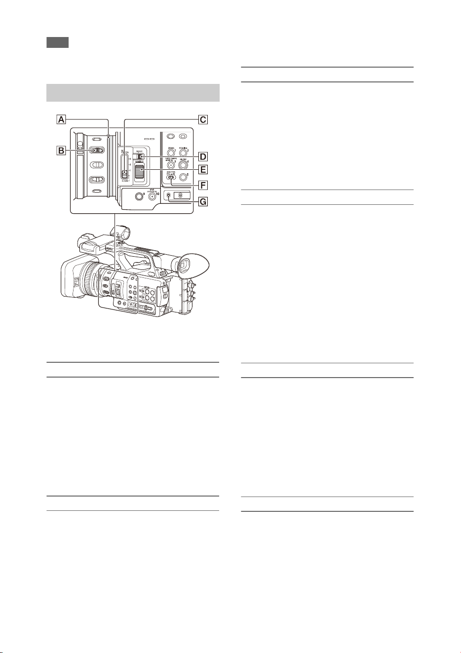
Adjusting the light level (ND filter)
You can shoot a subject with the proper
brightness by using the ND FILTER switch C
when the recording environment is too bright.
The camcorder features two ND filter modes.
You can switch the mode using the ND FILTER
mode switch D.
Preset mode
Set the ND FILTER mode switch D to PRESET,
then set the ND FILTER switch C to the
following.
CLEAR: ND filter is not used.
1: Filter density set using ND Filter >Preset1 in
the Camera menu. The default setting is 1/4.
2: Filter density set using ND Filter >Preset2 in
the Camera menu. The default setting is 1/16.
3: Filter density set using ND Filter >Preset3 in
the Camera menu. The default setting is 1/64.
You can also set the filter in the same way as the
ND FILTER switch using the direct menu
(page 37).
Variable mode
Set the ND FILTER mode switch D to PRESET,
then set the ND FILTER switch C to the
following.
CLEAR: ND filter is not used.
1, 2, 3: You can set the filter density in a
continuous range from 1/4 to 1/128 using the ND
control dial E.
The ND FILTER switch B position (1/2/3) does
not affect the filter density adjustment.
Auto ND filter
When the ND FILTER mode switch is set to
VARIABLE and the ND FILTER switch is in
position 1 to 3, the density of the ND filter can be
adjusted automatically by setting Auto Exposure
>Auto ND Filter (page 92) in the Camera menu to
On.
You can also set Auto ND Filter on/off and set
ND CLEAR in the direct menu (page 37).
When Auto ND Filter is off, you can also select
the density of the ND filter in the direct menu.
Setting auto exposure
Auto exposure controls excessive brightness to an
appropriate level using auto ND filter, iris, gain,
and shutter functions.
Set the control mode using Auto Exposure
(page 92) >Mode in the Camera menu, and set the
level using Level.
You can also set the control mode and correction
level in the direct menu (page 37).
Using the flicker reduction function
Set Flicker Reduce (page 93) >Mode in the
Camera menu to Auto or On, and set Frequency
to the power supply frequency (50 Hz or 60 Hz).
Note
• If the frame rate for shooting is close to the power
supply frequency, flicker may not be completely
reduced when using the flicker reduction function. In
this case, use the electronic shutter.
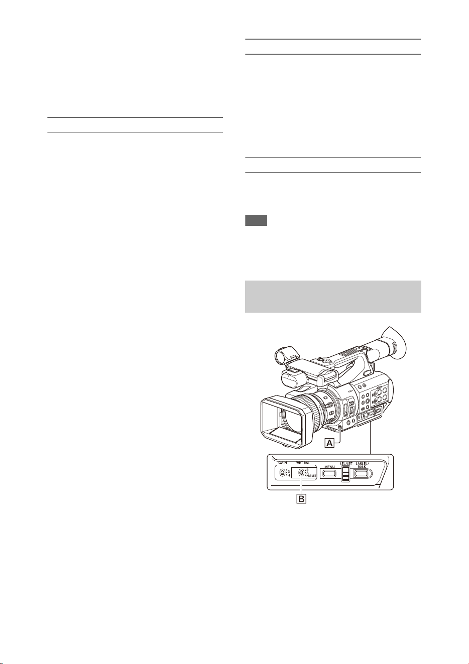
You can select the adjustment mode to suit the
shooting conditions.
Preset mode
This mode adjusts the color temperature to a
preset value (factory default is 3200K). Select this
mode when you have no time to adjust the white
balance or when you wish to fix the white balance
to the preset set using White (page 95) >Preset
White in the Paint menu.
Adjusting for natural colors (white
balance)

33
Memory A mode, Memory B mode
This mode adjusts the white balance to the setting
saved in memory A or B, respectively.
Press the WB SET button A to execute auto
white balance adjustment and store the adjusted
value in memory A or memory B.
ATW (Auto-Tracing White balance) mode
In this mode, the camcorder automatically adjusts
the white balance to the appropriate condition.
The white balance is automatically adjusted when
the color temperature of the light source changes.
You can select the speed of adjustment (five
steps) using White Setting >ATW Speed
(page 95) in the Paint menu.
You can freeze the current white balance setting
by assigning the ATW Hold function to an
assignable button (page 40), and pressing the
assignable button to temporarily pause ATW
mode.
Note
• It may not be possible to adjust to the appropriate
colors using ATW, depending on the lighting and
subject conditions.
Examples:
When a single color dominates the subject, such as
sky, sea, ground, or flowers.
When the color temperature is extremely high or
extremely low.
If the appropriate effect cannot be obtained because
the ATW auto tracking speed is slow or for other
reasons, run auto white balance.
Using the switch
Select the mode using the WHT BAL switch B.
B: ATW mode or Memory B mode
A: Memory A mode
PRESET: Preset mode
ATW mode is assigned to the B position of the
WHT BAL switch at the factory. You can change
the setting so that Memory B mode is selected
using White Setting >White Switch<B>
(page 95) in the Paint menu.
Setting the camcorder to Full Auto mode
(page 27) forcibly activates ATW mode.
Assigning the ATW on/off function to an
assignable button (page 40) permits you to
independently activate/deactivate ATW when
Full Auto mode is off.
Using the direct menu
Press the DISPLAY button (page 11) to display
the selected mode and color temperature on the
screen (page 12).
ATW: ATW mode
W:A: Memory A mode
W:B: Memory B mode
W:P: Preset mode
You can change the adjustment mode to the
following in the direct menu (page 37).
When the WHT BAL switch is set to the B
position, ATW mode and Memory B mode can be
set.
When the WHT BAL switch is set to the A
position, ATW mode and Memory A mode can be
set.
When the WHT BAL switch is set to the PRESET
position, ATW mode and Preset mode can be set.
You can set the color temperature in the direct
menu when not set to ATW mode.
You can change the color temperature in the
direct menu by selecting the color temperature
indicator. In preset mode, pressing the WB SET
button also sets the color temperature.
Switching preset mode using an
assignable button
Assign Preset White Select to an assignable
button (page 40). You can then switch preset
mode values in the order 3200K, 4300K, 5600K,
and 6300K each time you press the button.
Executing auto white balance
1 To save an adjustment value in
memory, select Memory A mode or
Memory B mode.
2 Place white paper (or other object) in a
location with the same lighting source
and conditions as the subject, then zoom
in on the paper to show white on the
screen.
3 Adjust the brightness.
Adjust the iris as described in “Shooting
using manual iris” (page 31).
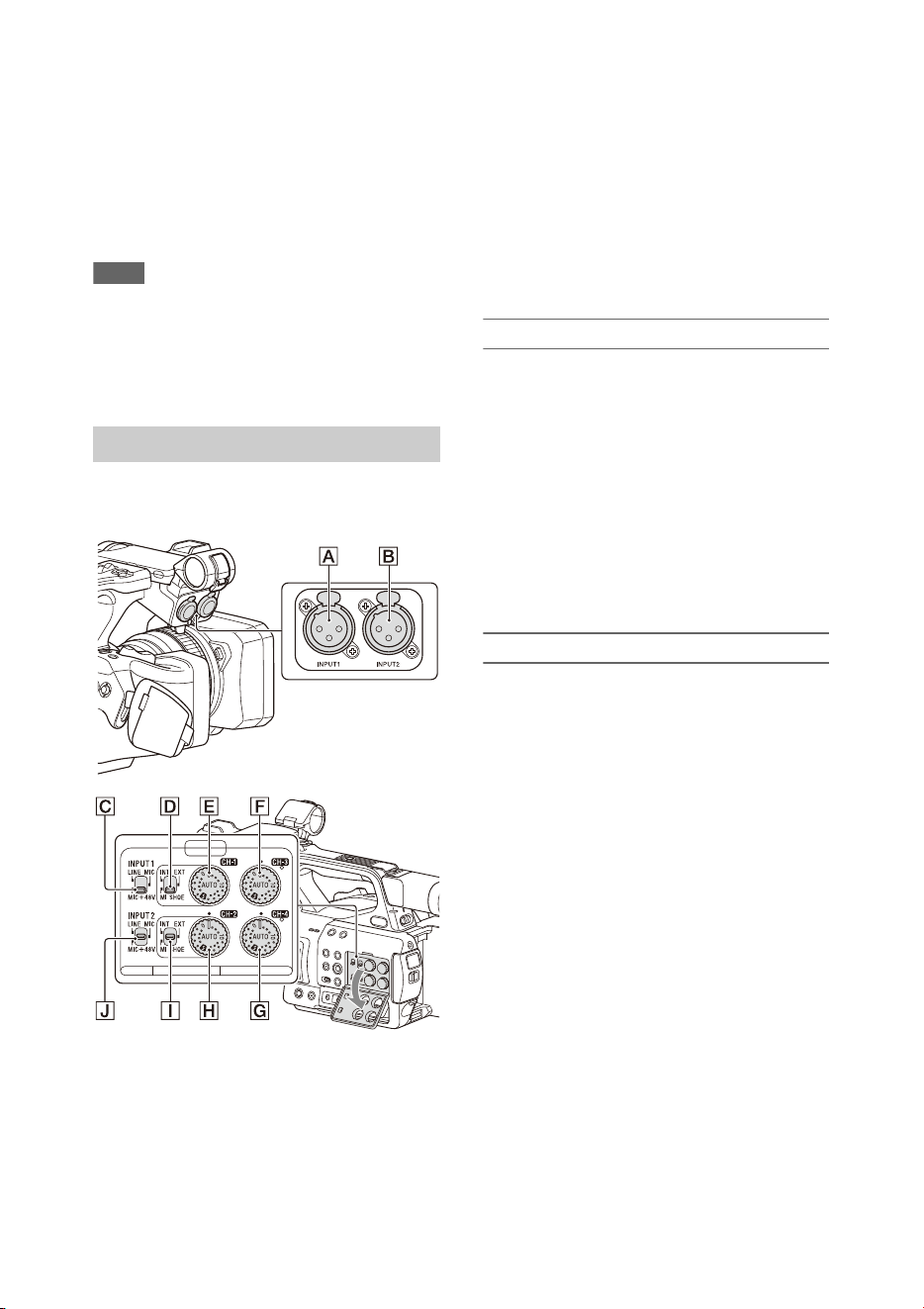
34
4 Press the WB SET button A.
When you execute the adjustment in a
memory mode, the adjusted value is stored in
the memory (A or B) selected in step 1.
If auto white balance is executed in ATW
mode, the white balance adjustment returns
to the ATW mode white balance when
adjustment ends.
Notes
• Auto white balance adjustment cannot be performed
when in Preset mode.
• If the adjustment is not successful, an error message is
displayed on the screen. If the error message persists
after repeated attempts to set white balance, contact
your Sony service representative.
The following connectors, switches and dials
allow you to set the sound to be recorded.
External audio input connectors and selector
switches
AUDIO INPUT1 connector A
AUDIO INPUT2 connector B
INPUT1 switch C
INPUT2 switch J
Audio source switches
CH1 (INT/EXT/MI SHOE) switch D
CH2 (INT/EXT/MI SHOE) switch I
Switches for setting the audio level
AUDIO LEVEL (CH1) dial E
AUDIO LEVEL (CH2) dial H
AUDIO LEVEL (CH3) dial F
AUDIO LEVEL (CH4) dial G
Refer to the block diagrams (page 143).
Using the internal microphone
You can record sound using the internal
microphone.
To record on CH1, CH2
Set the CH1 (INT/EXT/MI SHOE) switch
D and CH2 (INT/EXT/MI SHOE) switch
I to INT.
To record on CH3, CH4
Select Internal MIC using Audio Input
(page 101) >CH3 Input Select and CH4
Input Select in the Audio menu.
Using an external audio device
Mixers and other external audio devices are
supported.
To record on CH1, CH2
1 Set the CH1 (INT/EXT/MI SHOE)
switch D and CH2 (INT/EXT/MI
SHOE) switch I to EXT.
When Audio Input >CH2 EXT Input Select
in the Audio menu is set to INPUT2, the
sound from the AUDIO INPUT1 connector
will be recorded on CH1 and the sound from
the AUDIO INPUT2 connector will be
recorded on CH2.
When CH2 EXT Input Select is set to
INPUT1, the sound from the AUDIO
INPUT1 connector will be recorded on both
CH1 and CH2.
2 Set the INPUT1/INPUT2 switches (C/
J) to LINE.
3 Connect an external audio device to the
AUDIO INPUT1/AUDIO INPUT2
connectors (A/B ).
Setting the audio to record

35
To record on CH3, CH4
1 Select INPUT1 using Audio Input
(page 101) >CH3 Input Select and
INPUT2 using CH4 Input Select in the
Audio menu.
If INPUT1 is selected using CH4 Input
Select, the sound from the AUDIO INPUT1
connector will be recorded on both CH3 and
CH4.
2 Perform steps 2 and 3 as described in
“To record on CH1, CH2.”
Using an external microphone
An electret condenser microphone or other
devices can be connected and used for recording.
To record on CH1, CH2
1 Set the CH1 (INT/EXT/MI SHOE)
switch D and CH2 (INT/EXT/MI
SHOE) switch I to EXT.
When Audio Input >CH2 EXT Input Select
in the Audio menu is set to INPUT2, the
sound from the AUDIO INPUT1 connector
will be recorded on CH1 and the sound from
the AUDIO INPUT2 connector will be
recorded on CH2.
When CH2 EXT Input Select is set to
INPUT1, the sound from the AUDIO
INPUT1 connector will be recorded on both
CH1 and CH2.
2 Set the INPUT1/INPUT2 switches (C/
J).
MIC: For microphone that does not require
phantom power.
MIC+48V: For microphone that requires
+48 V phantom power.
Notes
• Selecting MIC+48V and connecting a
microphone that is not compatible with a +48 V
source may damage the connected device. Check
before connecting the device.
• If noise is a concern on connectors with no device
connected, set the corresponding INPUT1/
INPUT2 switches to LINE.
3 Open the cover by pulling up the handle
of the microphone holder.
4 Attach a microphone, then close the
microphone holder to secure the
microphone.
5 Connect the microphone cable to the
AUDIO INPUT1/AUDIO INPUT2
connectors (A/B ).
When you use a stereo microphone (two
XLR plugs), connect the L (left) channel plug
to the AUDIO INPUT1 connector, and the R
(right) channel plug to the AUDIO INPUT2
connector.
To record on CH3, CH4
1 Select INPUT1 using Audio Input
(page 101) >CH3 Input Select and
INPUT2 using CH4 Input Select in the
Audio menu.
If INPUT1 is selected using CH4 Input
Select, the sound from the AUDIO INPUT1
connector will be recorded on both CH3 and
CH4.
2 Perform steps 2 to 5 as described in “To
record on CH1, CH2.”
Using a multi-interface shoe compatible
microphone
To record on CH1, CH2
1 Set the CH1 (INT/EXT/MI SHOE)
switch D and CH2 (INT/EXT/MI
SHOE) switch I to MI SHOE.
2 Attach a microphone to the multi-
interface shoe.
To record on CH3, CH4
1 Select Shoe CH1 using Audio Input
(page 101) >CH3 Input Select and Shoe
CH2 using CH4 Input Select in the
Audio menu.
2 Attach a microphone to the multi-
interface shoe.
Note
• Two microphones cannot be connected to the front and
rear Multi Interface Shoe at the same time. The first
connected microphone is the active microphone.

36
Adjusting the audio recording level
Adjusting automatically (AGC)
Set the AUDIO LEVEL (CH1/CH2/CH3/
CH4) dials (E/H/F/G) to AUTO.
You can set whether the levels on CH1 and CH2
are automatically adjusted separately (Mono) or
together (Stereo) using Audio Input (page 101)
>CH1&2 AGC Mode in the Audio menu.
Similarly, you can set whether the levels on CH3
and CH4 are automatically adjusted separately
(Mono) or together (Stereo) using CH3&4 AGC
Mode.
Adjusting manually
During shooting or standby, turn the
AUDIO LEVEL (CH1/CH2/CH3/CH4)
dials (E/H/F/G) of the corresponding
channels in the range 0 to 10 to adjust the
recording level.
To reduce wind noise, set Audio Input >CH Wind
Filter in the Audio menu to On (page 101).
Audio recording in special recording
modes
Audio is not recorded in Interval Rec mode or
Slow & Quick Motion mode.
Enabling the image stabilization (SteadyShot)
function suppresses image shaking caused by
camera movement when recording.
Press the STEADY SHOT button on the
lens.
The SteadyShot mode turns on/off each time you
press the button.
The setting is displayed on the LCD/viewfinder
screen.
Note
• When shooting using a tripod for stability, set
SteadyShot to Off.
Setting the timecode
Set the timecode to record using Timecode
(page 107) in the TC/UB menu.
Setting user bits
You can add an 8-digit hexadecimal number to
the recorded image as user bits. You can also set
the user bits to the current time.
Set using Users Bit (page 107) in the TC/UB
menu.
Displaying time data
Press the DISPLAY button to display time data
on the screen (page 12).
The indication is switched among the timecode,
user bits, and recording duration each time you
press the DURATION/TC/U-BIT button
(page 11).
Image stabilization
Time data
Display Description
TCG **:**:**:** Timecode
CLK **:**:**:** Timecode (Clock mode)
UBG ** ** ** ** User bits
DUR **:**:**:** Duration from the beginning
of recording

37
You can check status and change settings for
some items displayed directly on the LCD/
viewfinder screen.
The Direct Menu function is used by assigning
the function to an assignable button.
The following items can be configured.
• Auto focus mode
•ATW
•Preset White
• Color Temp <A>/Color Temp <B>
• Scene File
• ND Filter Position
• Auto ND Filter
•ND Filter value
• Auto Iris
• Iris value
•AGC
• Gain value (H/M/L/Turbo)
•ECS
• Auto Shutter
• Shutter Speed value
• Shutter Angle value
• Auto Exposure Mode
• Auto Exposure Level
•S&Q Frame Rate
Note
• Direct menu operation is not available when Full Auto
mode (page 27) is on (FULL AUTO button indicator is
lit).
1 Press the assignable button assigned
with Direct Menu.
When information is displayed on the LCD/
viewfinder screen using the DISPLAY
button, only the items on the screen that can
be configured using the direct menu are
selectable using the cursor.
When information is not displayed on the
LCD/viewfinder screen, only items that can
be configured using the direct menu are
displayed and are selectable using the cursor.
2 Move the cursor to the desired item
using the V/v/B/b button or SEL/SET
dial, and press the SET button or SEL/
SET dial.
The direct menu for the selected item
appears.
3 Select a setting using the V/v button or
SEL/SET dial, and press the SET
button or SEL/SET dial.
The cursor disappears and the new setting is
displayed.
Press the assignable button assigned with
Direct Menu again or wait 3 seconds without
performing any action to close the direct
menu and return to the shooting screen.
You can open the direct menu by setting Menu
Settings >Direct Menu with <SET> (page 123) in
the System menu to On and pressing the SET
button or SEL/SET dial. However, the face
detection AF registered face function becomes
unavailable.
The camcorder can detect people’s faces and then
adjust the focus on faces.
This function is available only when focus
adjustment is in AF mode or during push auto
focus.
When faces are detected, gray face detection
frames are displayed. The frames change to white
after auto focus is established. When multiple
individuals are detected, the main subject is
automatically determined.
Set the face detection AF action using Focus
(page 91) in the Camera menu.
Face Only AF: The camera detects the faces of
subjects (people) and focuses only on their
faces. While a face is not detected, AF is
temporarily stopped (MF), and the Face Only
AF mode auto focus paused icon
(page 12) is displayed. This mode is effective
when face detection has not stabilized.
Face Priority AF: The camera detects the faces
of subjects (people) and prioritizes the
focusing on the faces. When a face is not
detected, focusing is in AF mode (default
setting).
Off: The face detection AF function is disabled.
Useful Functions
Direct menu operation
Face detection AF
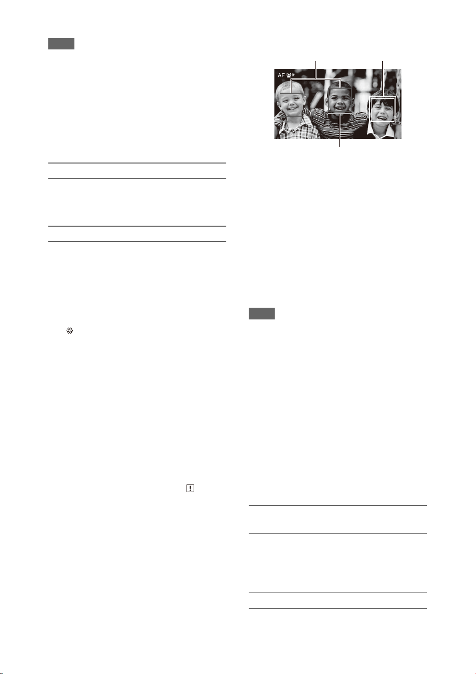
38
Notes
• During push auto focus operation, Face Priority AF is
activated even if Face Only AF is currently selected.
• Face detection AF is not available in the following
cases.
In FULL MF mode
When the FOCUS switch is set to MANUAL
(excluding during push auto focus operation)
When the recording format is DVCAM
• If you turn the camcorder off while Face Only AF is
selected, the mode automatically switches to Face
Priority AF when the camcorder is next turned on.
Hiding face detection frames
You can show/hide face detection frames using
Display On/Off >Face Detection Frame
(page 105) in the LCD/VF menu.
Focusing on a registered face
During face detection AF operation, you can
register a face for a subject (person) for focusing
on that face.
Only one face can be registered. Registering a
face overwrites the existing registration.
When a face is registered, the detection frame
changes to a double frame, and the registered face
icon (page 12) is displayed.
In face detection AF, the following actions occur
depending on the combination of registered face
and face detection AF operating mode.
Face Priority AF (with registered face): If
the camera detects the registered face, the
camera focuses on that face. If the registered
face is not detected, normal Face Priority AF
is activated.
Face Only AF (with registered face): If the
camera detects the registered face, the
camera focuses on that face. While the
registered face is not detected, AF is
temporarily stopped (MF), and the Face Only
AF mode auto focus paused icon
(page 12) is displayed. This mode is effective
when you want to auto focus on the
registered person.
Setting the registered face
Move the face selection cursor (orange
underline) to the face to register using the V/
v/B/b button, and press the SET button or
SEL/SET dial.
Clearing the registered face
Move the selection cursor to the registered face
using the V/v/B/b button, and press the SET
button or SEL/SET dial.
The registered face is cleared, the face frame
becomes a single frame, and the registered face
icon disappears.
When faces are detected with the registered face
frame not displayed and the face selection cursor
(orange) displayed, you can clear the registered
face by pressing the SET button or SEL/SET dial
twice.
Notes
• Faces may not be detected depending on the recording
environment, condition of the subject, or the settings.
• You may not be able to get the proper effect, or objects
other than people’s faces may be detected as a face, in
some recording environments. In this case, set the face
detection AF function to Off.
• Registration of the face of the intended individual for
focusing before shooting is recommended.
• Face registration may not be successful depending on
hairstyle, facial decoration, or if not directly facing the
camera. In this case, the face frame may become a
double frame, but the registered face icon is not
displayed and the face is not registered.
• If a face has already been registered, clearing the
existing face and then registering the new face is
recommended.
• The registered face function is not available when
Menu Settings >Direct Menu with <SET> (page 123)
in the System menu is set to On.
Switching face detection AF operation
using an assignable button
Assign Face Detection AF to an assignable button
(page 40). You can then switch face detection AF
operation in the order Face Priority AF, Face
Only AF, and Off each time you press the button.
Setting using the direct menu
You can also set the face detection AF operation
using the direct menu (page 37).
Face selection cursor (orange)
Registered face frame
(double white frame)
Other faces (gray)

39
You can output color bars instead of the camera
image by setting Color Bars (page 93) >Setting in
the Camera menu to On. The image output is
restored when set to Off.
A 1 kHz reference audio tone can also be output
with the color bars by setting Audio Input
(page 101) >1kHz Tone on Color Bars in the
Audio menu to On.
The color-bar signal and reference-tone signal are
output from the SDI OUT, HDMI OUT, and
VIDEO OUT (color bars only) connectors.
You can set the type of color bars using Color
Bars >Type in the Camera menu.
Notes
• Color bars cannot be output when the camcorder is in
Slow & Quick Motion mode.
• You cannot switch to color bars while recording
(switching from color bars to the camera image is
available).
Recording shot marks for important video/audio
scenes of a clip recorded in exFAT or UDF mode
displays the marked scenes on the essence mark
thumbnail screen (page 78), which only displays
scenes with shot marks, for simple cueing and
editing efficiency.
On this camcorder, two types of shot marks are
supported (shot mark 1 and shot mark 2).
Shot marks can be recorded as needed during
recording or can be added after recording while
checking the playback pictures.
Inserting shot marks during recording
Assign the Shot Mark1 or Shot Mark2 function to
an assignable button (page 40), then press the
button at the scene where you want to insert a shot
mark.
For details about adding shot marks after recording,
see “Adding shot marks during playback (exFAT,
UDF)” (page 73).
For details about naming shot marks using planning
metadata, see “Defining shot mark names in
planning metadata” (page 50).
You can add OK/NG/KEEP flags to clips
recorded in exFAT or UDF mode.
Adding flags allows you to filter the clips to
display only the required clips on the filtered clip
thumbnail screen (page 77).
Note
• Use the Lock/Unlock Clip setting (page 76) to protect
clips.
Adding a flag
You can add OK/NG/KEEP flags to clips during
recording or playback.
During recording or playback, press the
assignable button assigned with Clip Flag
OK/Clip Flag NG/Clip Flag Keep.
Deleting a flag
You can delete added OK/NG/KEEP flags from a
clip.
Press the assignable button assigned with
Clip Flag OK/Clip Flag NG/Clip Flag Keep
twice.
OK/NG/KEEP flags can also be added and deleted
from the thumbnail screen. For details, see “Adding/
deleting clip flags (exFAT, UDF)” (page 77).
You can review the last recorded clip on the
screen (Rec Review).
When recording is stopped, press the
assignable button assigned with Rec
Review.
The last 3 seconds, 10 seconds, or the entire clip
is displayed, depending on the Rec Review
(page 109) setting in the Recording menu.
The clip is played to the end, Rec Review ends,
and the camcorder returns to STBY (standby)
mode.
To stop Rec Review
Press the STOP button or an assignable
button assigned with Rec Review.
Color bars/reference audio tone
Shot marks
OK/NG/KEEP flags (exFAT, UDF)
Reviewing a recording (Rec
Review)

40
Notes
• Rec Review is not supported if the video format is
changed after recording a clip.
• The setup menus cannot be operated during Rec
Review.
• Rec Review is not available when the thumbnail screen
displays the filtered clip thumbnail screen.
There are ten assignable buttons (page 7) on the
camcorder to which you can assign functions.
Changing functions
Use Assignable Button (page 121) in the System
menu.
You can view the assigned functions on the
Assignable Button Status screen (page 15).
Default assigned functions
Button 1 Zebra
Button 2 Peaking
Button 3 Video Signal Monitor
Button 4 Network Client Mode
Button 5 Off
Button 6 Off
Button 7 Direct Menu
Button 8 Focus Magnifier
Button 9 Off
Button 10 Push Auto Iris
Assignable functions
For details about each function, see page 121.
•Off
• Push AF/Push MF
• Face Detection AF
• ND Filter Position
• Auto ND Filter
• Push Auto ND
• Push Auto Iris
• Turbo Gain
•AGC
•Shutter
• Auto Exposure Level
• Spotlight
• Backlight
• Flash Band Reduce
• Digital Extender ×2
• Handle Zoom
• Color Bars
• Preset White Select
•ATW
•ATW Hold
• Marker
•Zebra
• Peaking
• Video Signal Monitor
• Focus Magnifier
•Lens Info
•LCD/VF Adjust
• VF Mode
• Gamma Display Assist
•Display
•Rec
• S&Q Motion
• Clip Continuous Rec
• Picture Cache Rec
• Proxy Rec Start/Stop
• Rec Review
• Last Clip Delete
• Thumbnail
• Shot Mark1
• Shot Mark2
•Clip Flag OK
•Clip Flag NG
• Clip Flag Keep
•NFC
• Network Client Mode
•Streaming
• Auto Upload (Proxy)
• Direct Menu
• User Menu
•Menu
You can automatically record images at set
intervals by setting the number of frames per take
(Number of Frames) and the shooting interval
(Interval Time).
This function is an effective way to shoot slow-
moving subjects.
Assignable buttons
Interval recording (Interval Rec)
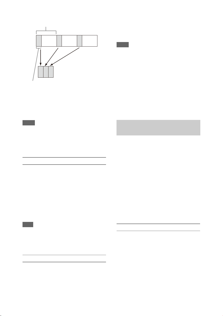
41
It is recommended to fix the camcorder to a tripod
or equivalent and use web remote control to start/
stop recording rather than pressing the record
button of the camcorder.
Notes
• Audio is not recorded in Interval Rec mode.
• Interval Rec cannot be set to On at the same time as
Picture Cache Rec, S&Q Motion, Clip Continuous
Rec, 2-slot Simul Rec, 4K & HD (Sub) Rec, or Proxy
Rec. When Interval Rec is set to On, these other
recording modes are forcibly set to Off.
Configuring before shooting
Configure Interval Rec (page 108) in the
Recording menu before shooting.
When Setting is set to On, Interval Rec mode is
activated and “Int Stby” appears on the screen.
When a video light compatible with the Multi
Interface Shoe is mounted, you can set Interval
Rec >Pre-Lighting in the Recording menu to On
so that the light turns on automatically 2 seconds,
5 seconds, or 10 seconds before recording starts.
Note
• When Pre-Lighting is set to On, the video light remains
turned on if the video light off time would be less than
5 seconds, according to the Interval Time setting, even
when Video Light Set is set to Rec Link or Rec Link +
Stby in the Camera menu.
Recording in Interval Rec mode
Start the recording after completing the required
setting.
Press the record button.
When you start recording, the “Int Stby”
indication changes and alternates between “Int
zRec” and “Int zStby.”
Notes
• While recording in Interval Rec mode, the Interval
Time and Number of Frames settings cannot be
changed. To change the settings, first stop recording.
• After starting recording in Interval Rec mode, Rec
Review operation is disabled, including during the
interval time.
• The timecode is recorded in Rec Run mode during
recording in Interval Rec mode (page 107).
• Some extra frames may be recorded if you stop
recording or switch the card slot while recording is
halted in Interval Rec mode.
• Interval Rec >Setting is automatically set to Off when
the ON/STANDBY switch is set to the STANDBY
position. However, the Interval Time and Number of
Frames settings are maintained.
Normally, a clip is created as an independent file
each time you start and stop recording. However,
this function allows you to start and stop
recording while continuously recording to the
same clip, for as long as the function remains
enabled.
This is convenient when you do not want to
generate a large number of short clips, and when
you want to record without worrying about
exceeding the clip limit. It is still easy to find
recording start points, because a Rec Start mark is
recorded at the recording start point each time you
start recording.
For details about recording formats compatible
with Clip Continuous Rec, see (page 131).
Configuring before shooting
Configure Clip Continuous Rec (page 108) in the
Recording menu before shooting.
When Setting is set to On, Clip Continuous Rec
mode is activated and “Cont Stby” appears on the
screen (page 12).
Configuring using assignable buttons
You can assign Clip Continuous Rec to an
assignable button (page 40), and switch the
function On/Off by pressing the button.
Number of frames in one take
(Number of Frames)
Shooting interval (Interval Time)
Continuous recording (Clip
Continuous Rec) (exFAT, UDF)

42
Notes
• Clip Continuous Rec cannot be set to On at the same
time as Interval Rec, Picture Cache Rec, S&Q Motion,
2-slot Simul Rec, or 4K & HD (Sub) Rec. When Clip
Continuous Rec is set to On, these other recording
modes are forcibly set to Off.
• Clip Continuous Rec mode cannot be used while
recording.
Recording in Clip Continuous Rec mode
Start the recording after completing the required
setting.
Press the record button.
When you start recording, the “Cont Stby”
indication changes to “Cont zRec” (z turns red).
Notes
• During recording or in recording standby mode (when
the “Cont Stby” indication is displayed), if you remove
the SxS memory card, the battery, or the power source,
the SxS memory card needs to be restored. Exit Clip
Continuous Rec mode and then remove the SxS
memory card. When “Cont Stby” indication is flashing
(once per second), you can remove the SxS memory
cards.
• Stop the recording after recording for two or more
seconds.
To exit, stop the recording.
To exit Clip Continuous Rec mode
In recording standby mode, set Clip Continuous
Rec (page 108) >Setting in the Recording menu
to Off, or press an assignable button assigned
with Clip Continuous Rec.
Limitations
A single continuous clip cannot be created if you
perform one of the following operations while the
camcorder is recording or in recording standby
mode. A new clip will be created when you next
start recording.
• Operate on a clip (lock, delete, or rename a clip)
• Change the memory card slot
• Change the recording format
• Set the ON/STANDBY switch to STANDBY
• Display the thumbnail screen
•Play a clip
• Exit Clip Continuous Rec mode
The camcorder always maintains a cache of video
and audio data for a set interval (maximum of 28
seconds) in internal storage memory when
shooting, allowing you to record several seconds
of footage before actually starting to record.
The Picture Cache Rec function can be used when
the recording format (page 118) is set to one of
the formats listed below.
• XAVC-I
• XAVC-L
• MPEG HD 422
• MPEG HD 420
Notes
• Picture Cache Rec cannot be set to On at the same time
as Interval Rec, Clip Continuous Rec, S&Q Motion, 2-
slot Simul Rec, 4K & HD (Sub) Rec, or Proxy Rec.
When Picture Cache Rec is set to On, these other
recording modes are forcibly set to Off.
• Picture Cache Rec mode cannot be selected while
recording or Rec Review is in progress.
• When Picture Cache Rec is set to On, the timecode is
recorded in Free Run mode regardless of the setting in
the TC/UB menu (page 107).
Configuring before shooting
Configure Picture Cache Rec (page 108) in the
Recording menu before shooting.
When Setting is set to On, Picture Cache Rec is
activated and “Cache” appears on the screen.
Configuring using assignable buttons
Assign Picture Cache Rec to an assignable button
(page 40), and switch the function On/Off by
pressing the button.
Recording in Picture Cache Rec mode
Start the recording after completing the required
setting.
Press the record button.
When you start recording, the “Cache” indication
changes to “zRec.”
To exit, stop the recording.
To cancel Picture Cache Rec
Set Picture Cache Rec >Setting in the Recording
menu to Off, or press an assignable button
assigned with Picture Cache Rec.
Picture cache recording (Picture
Cache Rec)
43
Notes
• Changing the recording format clears the video in
cache memory stored up to that point, and starts
caching new video. Consequently, picture cache
recording of pictures before changing format is not
possible if you start recording immediately after
changing format.
• If Picture Cache Rec is started or stopped immediately
after inserting an SxS memory card, cache data may
not be recorded on the card.
• Video is stored in cache memory when the Picture
Cache Rec function is set to On. Video prior to the
function being set to On is not cached.
• Video is not stored in cache memory while an SxS
memory card is being accessed, such as during
playback, Rec Review, or thumbnail screen display.
Picture cache recording of video during that interval is
not possible.
• When a Multi Interface Shoe compatible video light is
attached, cache recording prior to starting to record is
not possible, even if Video Light Set in the Camera
menu is set to Rec Link or Rec Link + Stby. The light
turns on/off when you press the record button.
When the file system is exFAT and the recording
format (page 118) is set to one of the formats
listed below, you can specify a recording frame
rate that is different from the playback frame rate.
Notes
• Slow & Quick Motion cannot be set during recording,
playback, or while the thumbnail screen is displayed.
• Slow & Quick Motion cannot be set to On at the same
time as Interval Rec, Clip Continuous Rec, Picture
Cache Rec, 2-slot Simul Rec, 4K & HD (Sub) Rec, or
Proxy Rec. When Slow & Quick Motion is set to On,
these other recording modes are forcibly set to Off.
• Audio recording is not supported in Slow & Quick
Motion mode.
Configuring before shooting
Configure S&Q Motion (page 107) in the
Recording menu before shooting.
When Setting is set to On, Slow & Quick Motion
mode is activated and “S&Q Stby” appears on the
screen.
Setting the recording frame rate using the direct
menu
You can set the recording frame rate in Slow &
Quick Motion mode using the direct menu
(page 37).
Configuring using assignable buttons
Assign S&Q Motion to an assignable button
(page 40), and switch the Slow & Quick Motion
mode On/Off by pressing the button.
You can set the frame rate for recording by
pressing and holding an assignable button to
display the recording frame rate setup screen.
Recording in Slow & Quick Motion mode
Start the recording after completing the required
setting.
Press the record button.
When you start recording, the “S&Q Stby”
indication changes to “S&Q zRec.”
Notes
• You cannot change the Frame Rate setting during Slow
& Quick Motion recording. To change the settings,
first stop recording.
• Rec Review operation is not supported during Slow &
Quick Motion recording.
• The timecode is recorded in Rec Run mode during
Slow & Quick Motion recording (page 107).
• When you are recording with a slow frame rate, the
camcorder may continue recording for a few more
seconds after you press the record button to stop
recording.
To exit, stop the recording.
To cancel Slow & Quick Motion
In recording standby mode, set S&Q Motion
>Setting in the Recording menu to Off, or press
an assignable button assigned with S&Q Motion.
Slow & Quick Motion
Recording
format
System
frequency
S&Q frame
rate
XAVC-I
2160P/1080P
59.94/29.97/
23.98/50/25
1 to 60 fps
(1 FPS units)
XAVC-L
2160P/1080P
MPEG HD422/
MPEG HD420
1080P
29.97/23.98 1 to 30 fps
(1 FPS units)
25 1 to 25 fps
(1 FPS units)
MPEG HD422
720P
59.94/29.97/
23.98
1 to 60 fps
(1 FPS units)
50/25 1 to 50 fps
(1 FPS units)
44
You can simultaneously record using both
memory cards A and B.
Configuring before shooting
Configure Simul Rec (page 108) in the Recording
menu before shooting.
Note
• 2-slot Simul Rec cannot be set to On at the same time
as Interval Rec, Clip Continuous Rec, Picture Cache
Rec, S&Q Motion, or 4K & HD (Sub) Rec. When 2-
slot Simul Rec is set to On, these other recording
modes are forcibly set to Off.
Recording in 2-slot Simul Rec mode
Start the recording after completing the required
setting.
Press the record button.
Notes
• Use the same type and same size of memory cards for
2-slot Simul Rec recording.
• SxS memory cards are recommended.
• SDHC cards are not supported in 2-slot Simul Rec
mode.
• 2-slot Simul Rec cannot be set during recording,
playback, or while the thumbnail screen is displayed.
• When a memory card in one slot becomes full, if a
memory card in the other slot is recordable, recording
continues as normal. When you replace memory cards
during normal continuous recording, simultaneous
recording and relay recording are not available.
• When you start recording in 2-slot Simul Rec mode, if
media is inserted in only one slot or the media in one
slot is full, video is recorded only on the recordable
media.
To exit, stop the recording.
To cancel 2-slot Simul Rec mode
In recording standby mode, set Simul Rec
>Setting in the Recording menu to Off.
Changing the setting of the record button
and handle record button
You can start/stop recording on the memory card
in each slot independently by using the grip
record button and handle record button.
The default setting starts/stops recording on
memory card A and memory card B
simultaneously by using either of the buttons.
• Rec Button: Handle Rec
Button:
To change the setting
Select Simul Rec >Rec Button Set in the
Recording menu.
This function allows you to record a 4K (QFHD)
video (main clip) and MPEG HD422 video
(subclip), that can be used for pre-editing,
simultaneously to a single SxS memory card.
The following recording formats for SxS memory
cards are supported for 4K & HD (Sub)
recording.
The recording format of the subclip is determined
by the system frequency of the main clip.
Note
• SD cards cannot be used for 4K & HD (Sub) recording.
Configuring before shooting
Configure 4K & HD (Sub) Rec (page 108) in the
Recording menu before shooting.
Simultaneous recording in 2 slots
(Simul Rec)
Rec Button Set Buttons and memory
cards
Rec Button:
Handle Rec
Button:
Starts/stops simultaneously
recording to memory cards A
and B using either button.
Rec Button:
Handle Rec
Button:
Starts/stops recording on
memory card A by using the
record button, and memory
card B by using the handle
record button.
Rec Button:
Handle Rec
Button:
Starts/stops recording on
memory card B by using the
record button, and memory
card A by using the handle
record button.
4K & HD (Sub) recording
Recording
format of main
clip
System
frequency
Recording
format of
subclip
XAVC-I
3840×2160P
XAVC-L
3840×2160P
29.97/25/
23.98
MPEG HD422
1920×1080P
59.94/50 MPEG HD422
1920×1080i

45
Notes
• 4K & HD (Sub) Rec cannot be set to On at the same
time as Interval Rec, Clip Continuous Rec, Picture
Cache Rec, S&Q Motion, 2-slot Simul Rec, or Proxy
Rec. When 4K & HD (Sub) Rec is set to On, these
other recording modes are forcibly set to Off.
• 4K & HD (Sub) cannot be set during recording,
playback, or while the thumbnail screen is displayed.
Recording in 4K & HD (Sub) recording
mode
Start the recording after completing the required
setting.
Press the record button.
During recording, “XAVC-I/Sub” or “XAVC-L/
Sub” is displayed on the right of the recording
format (codec) indicator on the screen.
To exit, stop the recording.
To cancel 4K & HD (Sub) recording mode
In recording standby mode, set 4K & HD (Sub)
Rec >Setting in the Recording menu to Off.
You can set the imaging to High Dynamic Range
(HDR) mode to record and output images with
BT.20202 equivalent color space and increased
dynamic range.
The High Dynamic Range function is enabled
when the file system is exFAT.
Note
• Not supported for DVCAM file formats.
Setting the dynamic range
Set Base Setting >Shooting Mode in the System
menu to HDR to set high dynamic range mode.
HDR settings
Set the HDR type using HDR Setting (page 118)
in the System menu.
HLG type when using HDR(HLG)
You can set the HLG type when the high dynamic
range mode is set to HDR(HLG).
For details, see (page 94).
Gamma display assist function setting
The LCD/viewfinder screen of the camcorder are
not HDR compatible, and are not suitable for
HDR display. Accordingly, the display can be
made more visible for easier shooting using the
gamma display assist function.
You can change the setting of the gamma display
assist function using Gamma Display Assist
(page 105) in the LCD/VF menu.
Note
• The gamma display assist function is used only for the
LCD/viewfinder screen. The settings are not applied to
the recorded image or output image.
The distance between the lens mount surface and
the image sensor plane (flange focal length or
flangeback) can be adjusted automatically.
Perform this adjustment if correct focus cannot be
obtained with the lens zoom at the wide angle and
telephoto positions.
When adjusted correctly, correct focus should be
maintained when changing the zoom position.
Notes
• If you use a subject with insufficient contrast, or move
the camcorder or subject during adjustment, the
adjustment cannot be made properly. Once the
adjustment begins, do not touch the camcorder body or
lens until it ends.
• Flange focal length auto adjustment is not possible
when shooting in Slow & Quick Motion mode.
• Make sure that no light source, such as a lamp, the sun,
or a bright window, is in the picture frame during
flange focal length adjustment.
• Contact your dealer if a flange focal length adjustment
chart is required.
1 Set the ON/STANDBY switch to the ON
position.
2 Remove attachments, such as a
conversion lens.
3 Set to normal shooting mode.
4 Set Marker (page 104) > S e t t i n g to O n or
Center Marker to a setting other than
Off in the LCD/VF menu to display the
center marker on the screen.
High dynamic range (HDR)
recording
Adjusting the flange focal length
automatically

46
5 Position the flange focal length
adjustment chart or other high contrast
object approximately 3 meters (10 ft)
away from the camcorder, and arrange
the lighting to obtain a satisfactory
video output.
Place the subject so that it appears at the
center of the screen at the telephoto end.
Also, make sure that no nearby object closer
to the camera than the chart enters the screen
at the wide-angle end.
6 Set the zoom to the telephoto end, and
align the center of the flange focal
length adjustment chart or other
subject with the center marker on the
screen.
7 Set Rec Format (page 118) >Video
Format to 3840×2160P and Frequency
to 59.94 or 50 in the System menu
8 Set the zoom to the wide angle end, turn
Full Auto mode off, and set the shutter
speed, gain, and iris to the following
settings (page 31).
Shutter speed: Auto shutter
Gain: 0dB
Iris: F1.9 (open)
9 Adjust the lighting and ND filter to an
appropriate brightness.
10 Set the ZOOM switch on the bottom of
the camcorder to SERVO (power zoom
mode).
11 Select Auto FB Adjust >Execute in the
Camera menu.
The flange focal length auto adjustment
starts.
A progress message appears on the screen
during adjustment.
After successful adjustment, a completion
message appears.
Note
• Do not change the ND filter while Auto FB Adjust
execution is in progress.
If you press the CANCEL button during
adjustment
Automatic adjustment of the flange focal length is
aborted and the condition before starting the
adjustment is restored.
If the flange focal length adjustment is not
successful
An error message appears.
Check the subject and lighting conditions, and
repeat the adjustment.
You can save setup menu settings in the
camcorder internal memory or on SD cards and
“Memory Stick” media. This allows you to
quickly recall an appropriate set of menu settings
for the current situation.
Configuration data is saved in the following
categories.
User files
User files save the setting items and data of the
customizable User menu.
You can save up to 64 files on an SD card or
“Memory Stick” media.
By loading this file into the camcorder memory,
you can customize the setup of the User menu.
ALL (all settings) files
ALL files save the configuration data of all
menus. You can save up to 64 files on an SD card
or “Memory Stick” media.
Note
• Device specific data (shading, output levels, and other
data that requires adjustment for the specific device) is
not saved.
Scene files
Scene files save settings for paint items
configured for scenes. You can save up to 5 files
in the internal memory of the camcorder, and up
to 64 files on an SD card or “Memory Stick”
media.
Media supported for saving configuration
data
SDXC memory cards* (Speed Class: 4 to 10,
non-UHS / Capacity: 2 to 32 GB, 64 GB and
larger)
Saving and loading configuration
data

47
SDHC memory cards* (Speed Class: 4 to 10,
non-UHS / Capacity: 2 to 32 GB)
SD memory cards* (Capacity: up to 2 GB)
“Memory Stick PRO-HG Duo”**
“Memory Stick PRO Duo”**
* Referred to as “SD card” in this document.
** Referred to as “Memory Stick” media in this
document.
Formatting (initializing) media
SD cards and “Memory Stick” media must be
formatted the first time they are used in the
camcorder.
An SD card or “Memory Stick” media to be used
with this camcorder must be formatted using the
format function of this camcorder. If a message
appears when the SD card or “Memory Stick”
media is inserted into the camcorder, format the
storage media.
1 Insert the SD card or “Memory Stick”
media into the UTILITY SD/MS slot
(page 9) with the label facing right.
2 Select Format Media (page 110) >
Utility SD/MS >Execute in the Media
menu. When a confirmation message
appears, select Execute again.
A message and progress status are displayed
while formatting is in progress, and the
access lamp is lit red.
When formatting is completed, a completion
message is displayed. Press the SET button
or SEL/SET dial to dismiss the message.
Note
• Formatting an SD card or “Memory Stick” media
erases all data. The data cannot be restored.
Checking the remaining capacity
You can check the remaining capacity on an SD
card or “Memory Stick” media on the Media
Status screen (page 15).
Notes
• A mark is displayed if the SD card or “Memory
Stick” media is protected.
• To use media formatted on the camcorder in the slot of
another device, make a backup of the data, then
reformat the media in the device to be used.
Saving a user file / ALL file
1 Insert the SD card or “Memory Stick”
media into the UTILITY SD/MS slot
(page 9) with the label facing right.
2 For a user file, select User File
(page 112) >Save Utility SD/MS
>Execute in the File menu.
For an ALL file, select All File >Save
Utility SD/MS >Execute in the File
menu.
A file save destination screen appears.
3 Select a “No File” row on the save
destination window using the V/v/B/b
button or SEL/SET dial, and press the
SET button or SEL/SET dial.
Selecting a row with a File ID entry will
overwrite the selected file.
The File ID is generated automatically, but
you can modify it.
4 Select Execute on the confirmation
screen using the V/v/B/b button or
SEL/SET dial, and press the SET
button or SEL/SET dial.
Loading a user file / ALL file
1 Insert the SD card or “Memory Stick”
media on which the file is saved into the
UTILITY SD/MS slot (page 9) with the
label facing right.
2 For a user file, select User File
(page 112) >Load Utility SD/MS
>Execute in the File menu.
For an ALL file, select All File >Load
Utility SD/MS >Execute in the File
menu.
A file list screen appears.
3 Select the file to load using the V/v /B/b
button or SEL/SET dial, and press the
SET button or SEL/SET dial.
A confirmation screen appears.

48
4 Select Execute using the V/v/B/b button
or SEL/SET dial, and press the SET
button or SEL/SET dial.
Notes
• The camcorder will reboot automatically after loading
configuration data.
• When All File >Load Network Data in the File menu
is set to Off, all settings in the ALL file are loaded
except the Network menu settings.
Saving a scene file
To save in internal memory
1 Select Scene File >Store Internal
Memory >Execute in the File menu
(page 112).
A scene file list screen appears.
If the File ID is set to “Standard” destination,
preconfigured standard settings are saved.
2 Select a save destination using the V/v/
B/b button or SEL/SET dial, and press
the SET button or SEL/SET dial.
The scene file is saved, overwriting any
existing file, in the selected destination.
3 Select Execute on the confirmation
screen using the V/v/B/b button or
SEL/SET dial, and press the SET
button or SEL/SET dial.
To save on an SD card or “Memory Stick” media
1 Insert the SD card or “Memory Stick”
media into the UTILITY SD/MS slot
(page 9) with the label facing right.
2 Select Scene File >Save Utility SD/MS
>Execute in the File menu (page 112).
A scene file save destination screen appears.
3 Select a “No File” row on the save
destination window using the V/v/B/b
button or SEL/SET dial, and press the
SET button or SEL/SET dial.
Selecting a row with a File ID entry will
overwrite the selected file.
The File ID is generated automatically, but
you can modify it.
4 Select Execute on the confirmation
screen using the V/v/B/b button or
SEL/SET dial, and press the SET
button or SEL/SET dial.
Loading a scene file
To load from internal memory
1 Select Scene File >Recall Internal
Memory >Execute in the File menu
(page 112).
A scene file list screen appears.
2 Select the file to load using the V/v /B/b
button or SEL/SET dial, and press the
SET button or SEL/SET dial.
A confirmation screen appears.
3 Select Execute using the V/v/B/b button
or SEL/SET dial, and press the SET
button or SEL/SET dial.
Scene files can also be loaded into the
camcorder using the direct menu (page 37).
To load from an SD card or “Memory Stick”
media
1 Insert the SD card or “Memory Stick”
media on which the file is saved into the
UTILITY SD/MS slot (page 9) with the
label facing right.
2 Select Scene File >Load Utility SD/MS
>Execute in the File menu (page 112).
A scene file list screen appears.
3 Select the file to load using the V/v /B/b
button or SEL/SET dial, and press the
SET button or SEL/SET dial.
A confirmation screen appears.
4 Select Execute using the V/v/B/b button
or SEL/SET dial, and press the SET
button or SEL/SET dial.

49
To change the File ID
1 For a user file, select User File >File ID
in the File menu (page 112).
For an ALL file, select All File >File ID
in the File menu (page 112).
For a scene file, select Scene File >File
ID in the File menu (page 112).
A screen for editing the File ID appears.
2 Select a character using the V /v/B/b
button or SEL/SET dial, and press the
SET button or SEL/SET dial.
3 Repeat step 2 as required.
4 When finished entering characters,
select Done using the V/v/B/b button or
SEL/SET dial, and press the SET
button or SEL/SET dial.
Planning metadata is information about shooting
and recording plans recorded in an XML file.
You can shoot using clip names and shot mark
names defined in advance in a planning metadata
file.
This camcorder can display clip names and shot
mark names defined in the following languages:
• Japanese
•English
• Chinese
•German
• French
• Italian
• Spanish
•Dutch
• Portuguese
•Swedish
•Norwegian
•Danish
•Finnish
Notes
• If you define clip and shot mark names in languages
other than those listed above, they may not be
displayed on the LCD/viewfinder screen.
• If you define clip and shot mark names in French,
Dutch, or Finnish, some characters are displayed in a
different but similar font.
Loading a planning metadata file
To record planning metadata together with clips,
it is necessary to load a planning metadata file
into the camcorders memory beforehand.
Note
• Data cannot be loaded from an SDXC/SDHC card.
When using an SxS memory card
Insert the SxS memory card with the planning
metadata file (.xml) saved to the directory below
into the camcorder card slot, then select and load
the file using Planning Metadata (page 112)
>Load Media(A) or Load Media(B) in the File
menu.
exFAT: XDROOT/General/Sony/Planning
UDF: General/Sony/Planning
Note
• Planning metadata files cannot be loaded when using
the FAT file system.
Confirming the detailed information in planning
metadata
After loading planning metadata into the
camcorder, you can check the detailed
information that it contains, such as file names,
date and time of creation, and titles.
Select Planning Metadata (page 112) >Properties
>Execute in the File menu.
Clearing the loaded planning metadata
To clear the planning data loaded in the
camcorder memory, proceed as follows:
Select Planning Metadata (page 112) >Clear
Memory >Execute in the File menu.
Defining a clip name in planning
metadata
The following two types of clip name strings can
be written in a planning metadata file.
• ASCII-format name, which is displayed on the
viewfinder screen
• A UTF-8 format name that is actually registered
as the clip name
When you specify a clip name in planning
metadata, the name is displayed under the
operation status indication on the viewfinder
screen.
Example of clip name strings
Use a text editor to modify the description for the
planning metadata <Title> tag.
Planning metadata

50
The shaded fields in the example are clip name
strings.
“Typhoon” is described in ASCII format (up to 44
characters). “Typhoon_Strikes” is described in
UTF-8 format (up to 44 bytes).
“
sp
” indicates a space and 3 indicates a carriage
return.
<?xml
sp
version="1.0"
sp
encoding="
UTF-8"?>3
<PlanningMetadata
sp
xmlns="http://
xmlns.sony.net/pro/metadata/
planningmetadata"
sp
assignId="
P0001"
sp
creationDate="
2011-08-20T17:00:00+09:00"
sp
lastUpdate="
2011-09-28T10:30:00+09:00"
sp
version="1.00">3
<Properties
sp
propertyId="
assignment"
sp
update="
2011-09-28T10:30:00+09:00"
sp
modifiedBy="Chris">3
<Title
sp
usAscii=" "
sp
xml:lang="en">
</Title>3
</Properties>3
</PlanningMetadata>3
Notes
• When you create a file, enter each statement as a single
line by breaking a line with a carriage return only after
the last character of the line, and do not enter spaces
except where specified with “sp.”
• A string of up to 44 bytes (or 44 characters) is valid as
a clip name.
If the UTF-8 format string exceeds 44 bytes, the first
44 bytes are used as the clip name.
If only a string in ASCII format is specified, the ASCII
format name up to the 44th character is used as the clip
name.
When neither the ASCII format name string nor UTF-
8-format name string is valid, a clip name in the
standard format is used.
Using a clip name defined in planning metadata
Load a planning metadata file that contains the
clip name into the memory of the camcorder, then
select Clip Naming (page 111) >Auto Naming
>Plan in the Media menu.
Clip names are generated by adding an
underscore (_) and a 5-digit serial number (00001
to 99999).
Example: Typhoon_Strikes_00001,
Typhoon_Strikes_00002, …
Notes
• If the serial number reaches 99999, it returns to 00001
upon the next recording.
• When you load another planning metadata file, the 5-
digit serial number returns to 00001.
Defining shot mark names in planning
metadata
When you record shot mark 1 or shot mark 2, you
can apply a name to the shot mark, using a string
defined in planning metadata.
Example of shot mark name strings
Use a text editor to modify the description for the
planning metadata <Meta name> tag.
The shaded fields in the example are shot mark
name strings.
Names can be either in ASCII-format (up to 32
characters) or UTF-8-format (up to 16
characters).
“
sp
” indicates a space and 3 indicates a carriage
return.
Note
• If a name string contains even one non-ASCII
character, the maximum length of that string is limited
to 16 characters.
<?xml
sp
version="1.0"
sp
encoding="
UTF-8"?>3
<PlanningMetadata xmlns="http://
xmlns.sony.net/pro/metadata/
planningmetadata"
sp
assignId="
H00123"
sp
creationDate="
2011-04-15T08:00:00Z"
sp
lastUpdate="
2011-04-15T15:00:00Z"
sp
version=
"1.00">3
<Properties
sp
propertyId=
"assignment"
sp
class="original"
sp
update="2011-04-15T15:00:00Z"
sp
modifiedBy="Chris">3
<Title
sp
usAscii="Football
Game"
sp
xml:lang="en">
Football Game 15/04/2011
</Title>3
<Meta
sp
name="_ShotMark1"
sp
content=" "/>3
<Meta
sp
name="_ShotMark2"
sp
content=" "/>3
</Properties>3
</PlanningMetadata>3
Typhoon
Typhoon_Strikes
Goal
Shoot
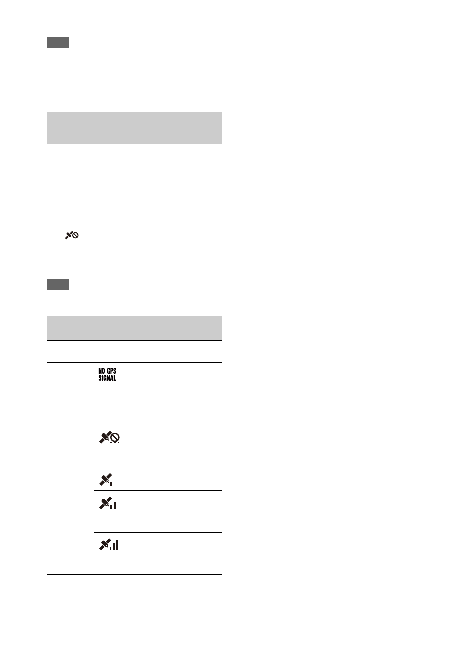
51
Note
• When you create a file, enter each statement as a single
line by breaking a line with a carriage return only after
the last character of the line, and do not enter spaces
except where specified with “
sp
” outside the shot mark
name strings.
Location and time information of video shot
when positioning is enabled is recorded onto
media loaded in the card slot of the camcorder,
and can be output as SDI.
1. Press the MENU button during standby.
2. Set GPS to On in the System menu.
is displayed when the camcorder is
seeking GPS satellites. When positioning is
established, location information is recorded
when shooting video.
Note
• The icon displayed varies, depending on the signal
reception from the GPS satellites.
• GPS is set to On by default. Location and time
information of video shot when positioning is
enabled is recorded by the camcorder. To record
location information, set GPS to On.
• It may take time to start positioning after
turning the camcorder on.
• If a positioning icon is not displayed after
several minutes, there may be a problem with
signal reception. Start shooting without location
information, or move to an area with a clear
view of the sky. Shooting when a positioning
icon is not displayed means that location
information will not be recorded.
• The GPS signal may not be received when
indoors or near tall structures. Move to a
location with a clear view of the sky.
• The recording of location information may be
interrupted, depending on the strength of the
received signal, even if a positioning icon is
displayed.
Acquiring location information
(GPS)
Positioning
status
Display GPS reception state
Off No display GPS is set to Off or an
error occurred.
Positioning
not available
Location information
could not be obtained
because GPS signal could
not be received. Move to a
location with a clear view
of the sky.
Searching for
satellites
Searching for satellites.
Several minutes may be
required to acquire
satellites.
Positioning A weak GPS signal is
being received.
A GPS signal is being
received. Location
information can be
acquired.
A strong GPS signal is
being received. Location
information can be
acquired.

52
You can record proxy data on an SD card
simultaneously while recording on an SxS
memory card.
SDXC memory cards* (Speed Class: 4 or
higher)
SDHC memory cards* (Speed Class: 4 or
higher / Capacity: up to 32 GB)
SD memory cards* (Speed Class: 4 or higher /
Capacity: up to 2GB)
Referred to as “SD card” in this document.
SD cards must be formatted the first time they are
used in the camcorder.
SD cards for use in the camcorder should be
formatted using the format function of the
camcorder. If a message appears when the SD
card is inserted into the camcorder, format the SD
card.
1 Insert the SD card media into the
UTILITY SD/MS slot (page 9) with the
label facing right.
2 Select Format Media (page 110)
>Utility SD/MS >Execute in the Media
menu. When a confirmation message
appears, select Execute again.
A message and progress status are displayed
while formatting is in progress, and the
access lamp is lit red.
When formatting is completed, a completion
message is displayed. Press the SET button
or SEL/SET dial to dismiss the message.
Notes
• Formatting an SD card erases all data on the card. The
card cannot be restored.
• SDXC cards are formatted in exFAT, and SDHC cards
are formatted in FAT32.
You can check the remaining capacity on an SD
card on the Media Status screen (page 15).
Note
• A mark is displayed if the SD card is protected.
To use media formatted on the camcorder in the
slot of another device
First, make a backup of the card, then reformat the card
in the device to be used.
Configuring before shooting
1 Set Proxy Rec >Setting in the Recording
menu to On.
2 Insert the SD card media into the
UTILITY SD/MS slot (page 9) with the
label facing right.
Note
• Proxy Rec cannot be set to On at the same time as
Interval Rec, Picture Cache Rec, S&Q Motion, or 4K
& HD (Sub) Rec. When Proxy Rec is set to On, these
other recording modes are forcibly set to Off.
Recording a proxy
Start the recording after completing the required
setting.
Press the record button.
Notes
• If the camcorder is turned off or the SD card is
removed while the SD card is being accessed, the
integrity of data on the card cannot be guaranteed. All
data recorded on the card may be discarded. Always
make sure the access indicator is off before turning off
the camcorder or removing the SD card.
• Take caution to prevent the SD card from flying out
when inserting/ejecting the card.
To exit, stop the recording.
When the recording on an SxS memory card is
stopped, proxy recording is also stopped.
Proxy Recording
Supported SD cards
Formatting (initializing) SD cards
Checking the remaining capacity
Proxy recording (Proxy Rec)

53
Setting the picture size
Select Proxy Rec >Proxy Format in the
Recording menu, and set the picture size.
Setting the audio channel
Select Proxy Rec >Audio Channel in the
Recording menu, and set the audio channel for
proxy recording.
The file name extension is “.mp4”.
The timecode is also recorded simultaneously.
The recorded file is stored under the “/PRIVATE/
PXROOT/Clip” directory.
The file name consists of the clip name recorded
on the SxS memory cards and a consecutive
number suffix.
In 2-slot Simul Rec mode, the clip name of slot A
has precedence.
• The consecutive number is kept even if the camcorder
is turned off. The consecutive number returns to 0001
by executing All Reset.
For details about clip names, see Clip Naming
(page 111) in the Media menu.
You can record proxy data independently to an
SD card in the UTILITY SD/MS slot without
recording to an SxS memory card.
The recording format of the proxy data is the
same as for simultaneous recording.
Configuring before shooting
1 Assign Proxy Rec Start/Stop to an
assignable button (page 40).
2 Set Proxy Rec >Setting in the Recording
menu to On.
3 Insert the SD card media into the
UTILITY SD/MS slot (page 9) with the
label facing right.
Recording
Start the recording after completing the required
setting.
Press the assignable button assigned with
Proxy Rec Start/Stop.
To stop recording, press the assignable button.
Changing proxy recording settings
About the recorded file
Storage destination of the
recorded file
About the file name
Recording proxy data only
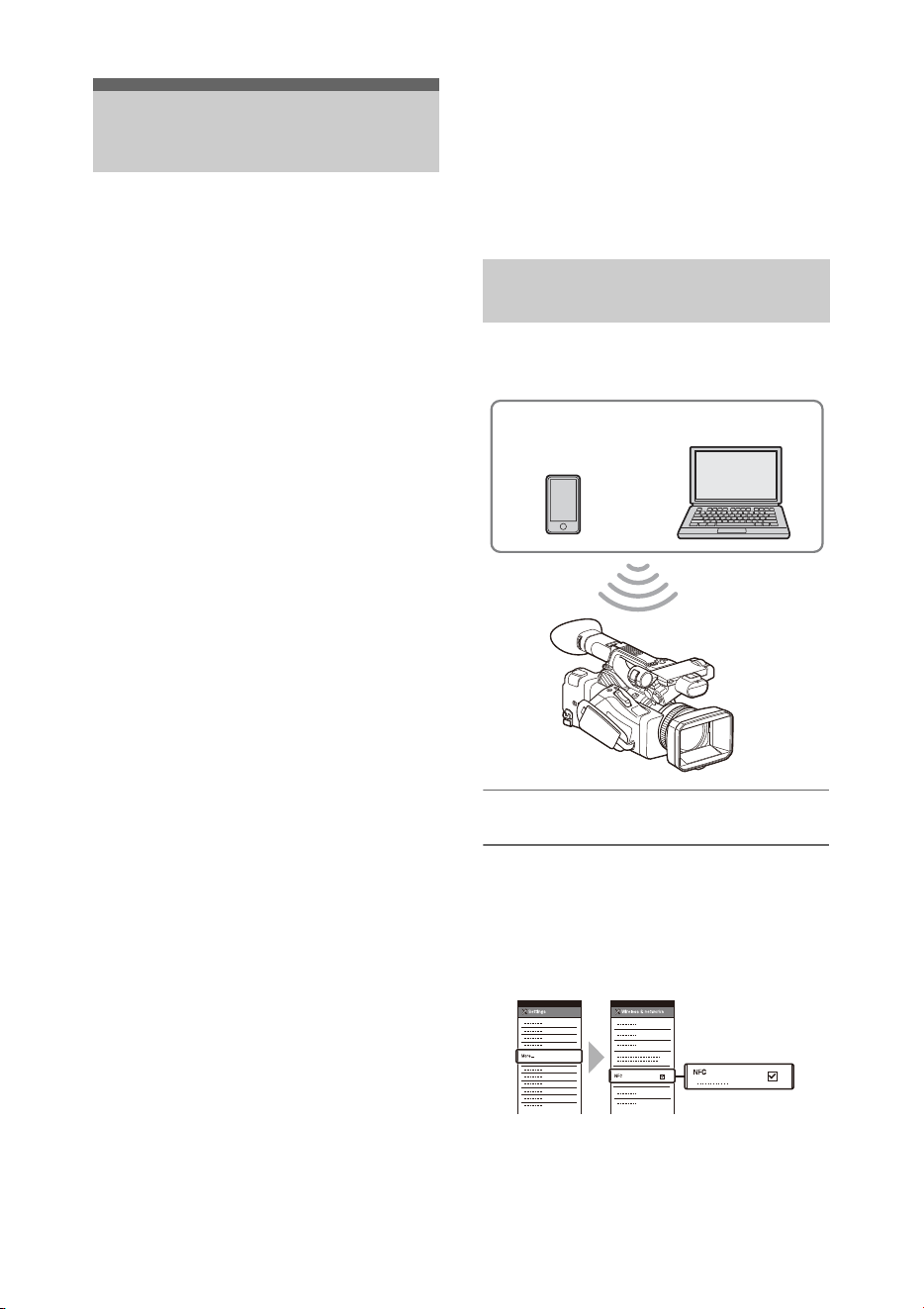
54
The camcorder can connect to smartphones,
tablets, and other devices using via LAN
connection.
Making a LAN connection between a device and
the camcorder enables you to do the following
using the web remote control (page 68) or
“Content Browser Mobile” application.
• Sending planning metadata (page 49)
Send and receive planning metadata using the
device and camcorder.
You can send planning metadata created
beforehand to the camcorder to specify clip
names.
• Remote operation via LAN
You can control the camcorder from a
smartphone, tablet, or computer that is
connected to the camcorder via a LAN.
• File transferring via LAN
You can transfer a proxy file (low resolution)
that is recorded on an SD card in the camcorder
or original file (high resolution) that is recorded
by the camcorder to the server via a LAN.
• Video monitoring via LAN
You can create a stream (H.264) from the
camera or playback video of the camcorder, and
monitor the video using the “Content Browser
Mobile” application from a device via a LAN.
“Content Browser Mobile” application
You can operate the camcorder remotely on the
device screen while streaming from the
camcorder, and configure settings of the
camcorder, using the “Content Browser Mobile”
application.
For details about the “Content Browser Mobile”
application, contact your Sony sales or service
representative.
Streaming high quality video using Sony QoS
technology (page 66)
You can stream high quality video using a Sony
Network RX Station (sold separately) or
XDCAM air* Connection Control Manager
(CCM) connected with the camcorder in network
client mode.
* XDCAM air is a cloud service that is provided by
Sony.
To use this service, registration is required.
XDCAM air is not provided in some regions. For
details on areas where the service is provided, refer to
the following site.
https://www.xdcam-air.com
For more details, contact a Sony professional sales
representative.
The camcorder works as an access point, and
connects to a device via a wireless LAN.
Connecting to an NFC-compatible device
with one-touch operation
Devices that support NFC can be connected (one-
touch connection) using NFC.
1 Open [Settings] on the device, select
[More], and place a check mark in the
[NFC] checkbox.
2 Turn the camcorder on.
Connecting to Other
Devices via LAN
Connecting using wireless LAN
access point mode
Smartphone/
tablet
Computer
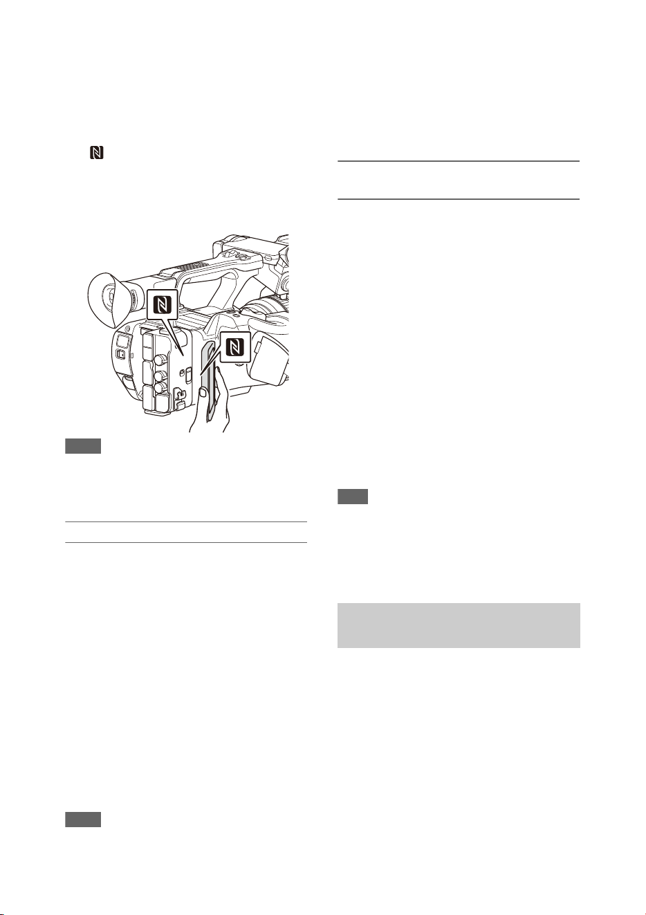
55
3 Activate the NFC function.
Press and hold (for 3 seconds) an assignable
button assigned with NFC or select Wireless
LAN >Wi-Fi >NFC in the Network menu to
activate NFC connection mode.
The NFC function is available only while
appears on the screen.
4 Touch the camcorder using the device.
The device connects to the camcorder and
“Content Browser Mobile” starts.
Notes
• Disable sleep mode and screen lock beforehand.
• Touch and hold the device still until the “Content
Browser Mobile” application launches (1 to 2
seconds).
Connecting to a WPS-compatible device
Devices that support WPS can be connected using
WPS.
1 Select Wireless LAN >Setting >Access
Point Mode in the Network menu.
2 Select Wireless LAN >WPS >Execute in
the Network menu.
3 Open the Network Settings or Wi-Fi
Settings on the device, and turn Wi-Fi
on.
4 Select the camcorder SSID from the
SSID list in Wi-Fi Network on the
device, then select WPS Push Button in
Option on the device to connect.
Notes
• The operation method differs depending on the device.
• For the SSID and password of the camcorder, check
AP Mode Settings (page 114) >Camera SSID &
Password in the Network menu.
5 Display the web remote control
(page 68). Or connect using the Content
Browser Mobile application.
Connecting by inputting an SSID and
password on a device
You can connect the camcorder to a device by
entering the SSID and password on a device.
1 Select Wireless LAN >Setting >Access
Point Mode in the Network menu.
2 Open the device Network Settings or
Wi-Fi Settings on the device, and turn
Wi-Fi on.
3 Connect the device to the camcorder by
selecting the camcorder SSID from the
SSID list in Wi-Fi Network and
entering the password.
For the SSID and password of the camcorder,
check AP Mode Settings (page 114)
>Camera SSID & Password in the Network
menu.
Note
• The operation method differs depending on the device.
4 Display the web remote control
(page 68). Or connect using the Content
Browser Mobile application.
The camcorder connects to an existing access
point of the wireless LAN as a client. The
camcorder and device connect via the access
point.
The 10 most recently connected access points are
displayed in the history.
The connection history is saved in an ALL file,
but the access passwords are not saved. Password
entry is required the next time you connect after
loading the ALL file.
Connecting using wireless LAN
station mode
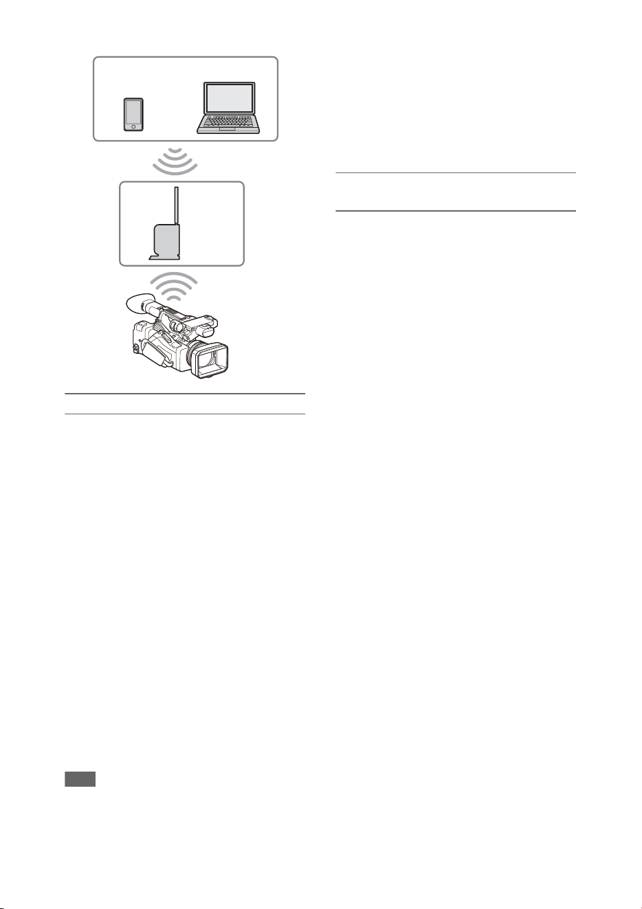
56
Connecting to an access point using WPS
If the access point is compatible with the WPS
function, you can connect to the access point with
simple settings.
1 Turn the access point on.
2 Turn the camcorder on.
3 Select Wireless LAN >Setting > Station
Mode in the Network menu.
4 Select Wireless LAN >WPS >Execute in
the Network menu.
5 Press the WPS button of the access
point.
For details about the operation of the WPS
button, refer to the operating instructions of
the access point.
When the connection is successful, the
network status indicator icon will show a
strength of 1 or higher on the LCD/
viewfinder screen.
Note
• If the connection fails, perform steps from step 1 again.
6 Connect the device to the access point.
For details about connecting, refer to the
operating instructions of the device.
7 Display the web remote control
(page 68). Or connect using the Content
Browser Mobile application.
Connecting to an access point using auto
network detection or manually
You can configure connection to a desired access
point from the setup menu.
You can configure connection to a desired access
point using the auto network detection function.
Connecting using the network auto detection
function
1 Perform steps 1 to 3 in “Connecting to
an access point using WPS” (page 56).
2 Select ST Mode Settings >Scan
Networks (page 114) >Execute in the
Network menu.
The camcorder starts detection of connection
destinations.
Detected destinations for connection are
displayed in the Scan Networks result list.
3 Select a connection using the V/v/B/b
button or SEL/SET dial, and press the
SET button or SEL/SET dial.
Momentarily, the network (access point)
details screen appears. The selected
connection is displayed in SSID.
4 Select Password, and set the password
on the password input screen.
If connected before network auto detection,
selecting an SSID displays the password
screen.
Set the password to return to the network
(access point) details screen.
5 Configure the following connection
settings.
• DHCP
Set the DHCP setting.
When you set to On, the IP address is
assigned to the camcorder automatically.
To assign the IP address to the camcorder
manually, set to Off.
Smartphone/
tablet
Access
point
Computer

57
• IP Address
Input the IP address of the camcorder. This
setting is available only when DHCP is set
to Off.
• Subnet Mask
Input the subnet mask of the camcorder.
This setting is available only when DHCP
is set to Off.
• Gateway
Input the default gateway for the access
point.
This setting is available only when DHCP
is set to Off.
• DNS Auto
Set to acquire DNS automatically.
When set to On, the DNS server address is
automatically acquired. This setting is
available only when DHCP is set to On.
• Primary DNS Server
Input the primary DNS server for the
access point.
This setting is available only when DNS
Auto is set to Off.
• Secondary DNS Server
Input the secondary DNS server for the
access point.
This setting is available only when DNS
Auto is set to Off.
6 When finished, select Connect to
connect to the access point.
Connecting manually
1 Perform steps 1 to 3 in “Connecting to
an access point using WPS” (page 56).
2 Select ST Mode Settings >Manual
Register (page 114) >Execute in the
Network menu.
Momentarily, the network (access point)
details screen appears.
3 Configure the following connection
settings.
•SSID
Input the SSID for the connection access
point.
• Security
Select the encryption method.
• Password
Input the password for the connection
access point.
• DHCP
Set the DHCP setting.
When you set to On, the IP address is
assigned to the camcorder automatically.
To assign the IP address to the camcorder
manually, set to Off.
•IP Address
Input the IP address of the camcorder. This
setting is available only when DHCP is set
to Off.
• Subnet Mask
Input the subnet mask of the camcorder.
This setting is available only when DHCP
is set to Off.
• Gateway
Enter the address of the gateway.
This setting is available only when DHCP
is set to Off.
• DNS Auto
Set to acquire DNS automatically.
When set to On, the DNS server address is
automatically acquired. This setting is
available only when DHCP is set to On.
• Primary DNS Server
Input the address of the primary DNS
server.
This setting is available only when DNS
Auto is set to Off.
• Secondary DNS Server
Input the address of the secondary DNS
server.
This setting is available only when DNS
Auto is set to Off.
4 When finished, select Connect to
connect to the access point.
You can connect with a device by connecting the
wired LAN connector of the camcorder to a LAN
switch using a LAN cable.
Connecting to a device using a
LAN cable
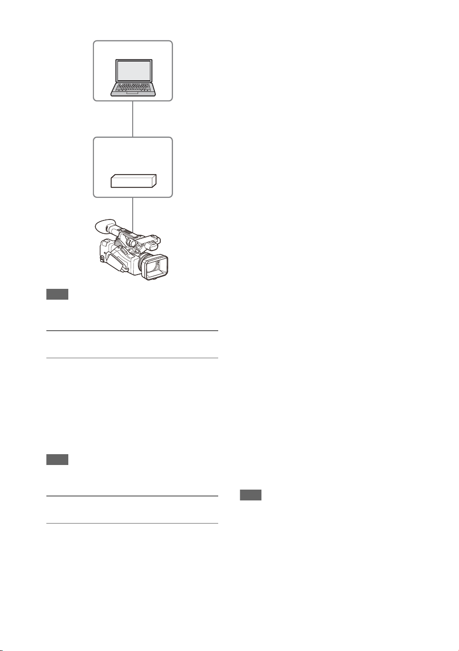
58
Note
• Wired LAN cannot be used at the same time as a
modem.
Wired LAN and video output
combinations
Wired LAN cannot be used if two or more of
Output On/Off (page 102) >SDI, HDMI, and
VIDEO in the Video menu are set to On.
All of them are set to On by default in Output On/
Off. To use a wired LAN, set two or more outputs
in Output On/Off to Off.
To use wired LAN and wireless LAN at the same
time, set all outputs in Output On/Off to Off.
Note
• When using wired LAN and video output at the same
time, the brightness of the LCD screen decreases.
LAN cable connections and wired LAN
settings
1 Connect the wired LAN connector of
the camcorder to a LAN switch using a
LAN cable.
2 Turn the camcorder on.
3 Set Wired LAN (page 115) >Setting in
the Network menu to On.
4 Configure connection settings using
Detail Settings in the menu.
• DHCP
Set the DHCP setting.
When you set to On, the IP address is
assigned to the camcorder automatically.
To assign the IP address to the camcorder
manually, set to Off.
•IP Address
Input the IP address of the camcorder. This
setting is available only when DHCP is set
to Off.
• Subnet Mask
Input the subnet mask of the camcorder.
This setting is available only when DHCP
is set to Off.
• Gateway
Enter the address of the gateway.
This setting is available only when DHCP
is set to Off.
• DNS Auto
Set to acquire DNS automatically.
When set to On, the DNS server address is
automatically acquired. This setting is
available only when DHCP is set to On.
• Primary DNS Server
Input the address of the primary DNS
server.
This setting is available only when DNS
Auto is set to Off.
• Secondary DNS Server
Input the address of the secondary DNS
server.
This setting is available only when DNS
Auto is set to Off.
5 When finished, select Set to apply the
settings.
Note
• Always select Set after changing the connection
settings. The settings are not applied if Set is not
selected.
Computer
LAN switch
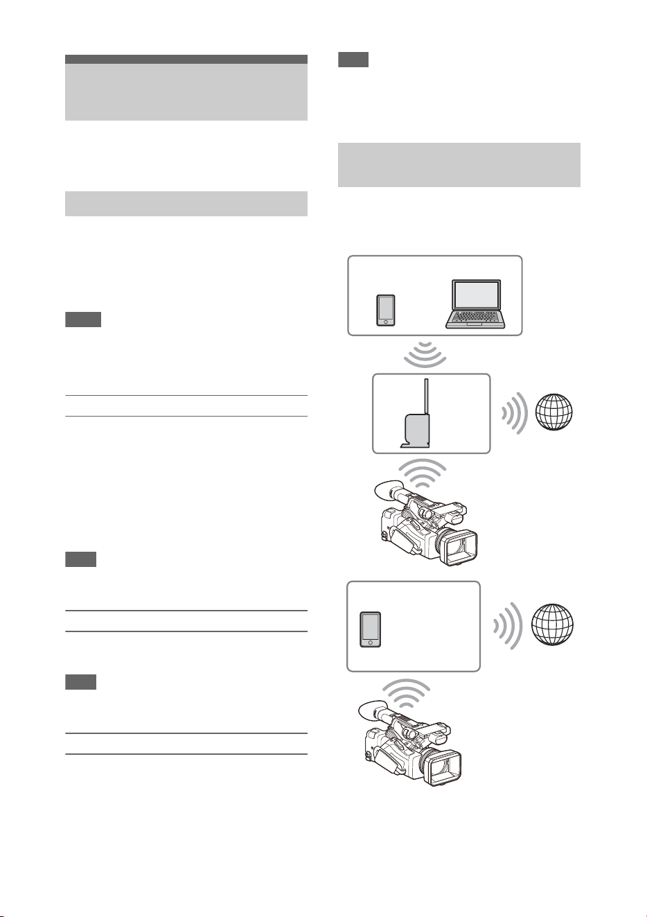
59
You can connect the camcorder to the Internet
using a modem, wired LAN, or wireless LAN.
You can connect the camcorder to the Internet via
a 3G/4G network by attaching an optional modem
to the unit.
For details about compatible modems, contact
your Sony dealer or a Sony service representative.
Notes
• A modem cannot be used at the same time as a wired
LAN.
• A modem cannot be used when using a BP-30 battery
pack.
Modem and video output combinations
A modem cannot be used if two or more of Output
On/Off (page 102) >SDI, HDMI, and VIDEO in
the Video menu are set to On.
All of them are set to On by default in Output On/
Off. To use a modem, set two or more outputs in
Output On/Off to Off.
To use a modem and wireless LAN at the same
time, set all outputs in Output On/Off to Off.
Note
• When using a modem and video output at the same
time, the brightness of the LCD screen decreases.
Attaching a modem to the camcorder
Attach the modem to the USB2.0 (HOST)
connector of the camcorder.
Note
• Attach/remove the modem while the camcorder is
turned off.
Connecting
1 Turn the camcorder on.
2 Set Modem >Setting in the Network
menu to On.
Note
• It may take some time (about 1 minute) to connect to a
3G/4G network. Wait until the network status indicator
(page 12) “3G/4G” icon shows a strength of 1 or
higher on the LCD/viewfinder screen.
You can connect the camcorder to the Internet in
Wi-Fi station mode via an optional wireless LAN
router or by tethering to a device.
Connect to the access point or device as described
in “Connecting using wireless LAN station
mode” (page 55).
Connecting to the
Internet
Connecting using a modem
Connecting using wireless LAN
station mode (Wi-Fi station mode)
Smartphone/
tablet
Access
point
Computer
Internet
Internet
Smartphone/
tablet
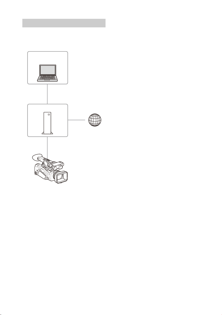
60
You can connect with a device by connecting the
wired LAN connector of the camcorder to an
Internet router using a LAN cable.
Connect to the Internet router as described in
“Connecting to a device using a LAN cable”
(page 57).
Connecting using a LAN cable
Router
Computer
Internet

61
The following table shows the availability of network functions in each network connection mode.
1) Functions of device connected with the camcorder via a network
List of functions for network connections
Network function Network connection mode
Access Point Station Modem Wired LAN Off
File transfer
(page 62)
× aa
a
1)
×
Streaming
(page 64)
× aaa×
Monitoring
(page 69)
a
1)
a
1)
×
a
1)
×
Remote control of
camcorder
(page 68)
a
1)
a
1)
×
a
1)
×

62
You can upload a proxy file or original file that is
recorded on the camcorder to a server on the
Internet or a server on a local network via a 3G/
4G network or access point.
Connecting to a network
Connect the camcorder to the Internet or local
network as described in “Connecting to the
Internet” (page 59) or “Connecting to Other
Devices via LAN” (page 54).
Registering a file transfer destination
Register the server for uploading in advance.
1 Select File Transfer >Server Settings1
(or Server Settings2, Server Settings3)
in the Network menu.
The transfer destination setup screen
appears.
2 Set each item on the transfer
destination setup screen.
Display Name
Enter the name of the server to display in the
transfer destination list.
Service
Displays the server type.
“FTP”: FTP server
Host Name
Enter the address of the server.
Port
Enter the port number of the server to
connect.
User Name
Enter the user name.
Password
Enter the password.
Passive Mode
Turn passive mode on/off.
Destination Directory
Enter the directory on the destination server.
Note
• When editing, “s” indicates characters that
cannot be changed. Correct operation is not
guaranteed when editing a directory name that
contains these characters. If you need to edit,
delete all the characters and re-enter a value.
Using Secure Protocol
Set whether to perform secure FTP
uploading.
Root Certificate
Load/clear a certificate.
• Load
Select Set in step 3, and import a CA
certificate.
* The certificate to be loaded must be in PEM
format, and should be written to the root
directory of the SD card with “certification.pem”
file name.
•Clear
Select Set in step 3, and clear a CA
certificate.
• None
Do not load or clear a certificate.
Notes
• Set the clock of the camcorder to the correct time
before importing a CA certificate.
• When recording in XAVC-I 3840×2160P 59.94/
50P, Load cannot be selected.
• In low voltage state, Load/Clear cannot be
selected for a CA certificate.
Root Certificate Status
Displays the load status of the certificate.
Reset
Reset the settings of Server Settings to the
defaults.
3 When finished, select Set to apply the
settings.
Always select Set after changing the settings.
The settings are not applied if Set is not
selected.
You can also register a server using the web
remote control “Registering a destination
server” (page 70).
Upload a file that is recorded on an SD card or an
original file that is recorded on an SxS memory
card to a server.
Uploading a File
Preparations
Selecting a file and uploading
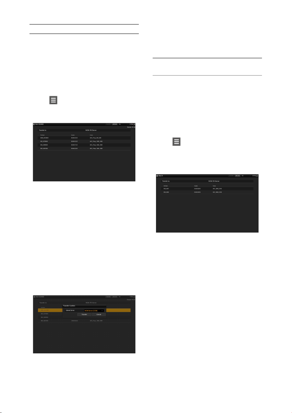
63
Uploading a proxy file on an SD card
1 Connect the camcorder and device
using a LAN connection (page 54).
2 Launch a browser on the device and
display the web remote control
(page 68).
3 Display the file list screen to select a file.
Tap >File Transfer >Slot SD/MS.
A file list screen for the media inserted in the
UTILITY SD slot appears.
4 Select the file to upload.
Tap the file to select it. To cancel, tap the file
again.
You can double-tap a file to play the file to
check its contents. (SD cards only)
5 Tap Transfer.
The server that you set using Default Server
in “Registering a destination server”
(page 70) appears.
To change the server, tap the server to
display the server list, then select a server.
Input the directory on the server in Directory
if necessary.
6 Tap Transfer.
The camcorder starts uploading the selected
file.
To cancel uploading, tap Cancel.
Uploading an original file on an SxS
memory card
1 Connect the camcorder and device
using a LAN connection (page 54).
2 Launch a browser on the device and
display the web remote control
(page 68).
3 Display the file list screen to select a file.
Tap >File Transfer >Slot A or Slot B.
A file list screen for the media inserted in slot
A or slot B appears.
Example: Slot A screen
4 Select the file to upload.
Tap the file to select it. To cancel, tap the file
again.
5 Tap Transfer.
The server that you set using Default Server
in “Registering a destination server”
(page 70) appears.
To change the server, tap the server to
display the server list, then select a server.
Input the directory on the server in Directory
if necessary.
6 Tap Transfer.
The camcorder starts uploading the selected
file.
To cancel uploading, tap Cancel.

64
Checking the file transfer
You can check the upload status on the Job List
screen that is displayed by tapping Job List on the
SD Card, Slot A, or Slot B screen (page 71).
Notes
• Up to 200 transfer jobs can be registered.
• The job list is retained when the camcorder is turned
off, but up to 10 minutes of recent progress
information may be lost if the battery pack is removed
or the camcorder is powered off without first setting
the ON/STANDBY switch to STANDBY.
• Jobs added after the battery low voltage state are not
saved in the job list.
If File Transfer >Auto Upload (Proxy) in the
Network menu is set to On and a network
connection exists, proxy files are automatically
uploaded to the server specified using Auto
Upload Server when recording ends.
For details, see “Uploading a proxy file
automatically” (page 70).
You can upload files with encryption using FTPS
in Explicit mode (FTPES) for the connection with
the destination file server.
Setting secure FTP transfer
For secure FTP transfer, set Using Secure
Protocol on the destination file server to ON and
import a certificate.
For details about configuration, see “Registering
a destination server” (page 70).
You can transmit the video and audio recorded/
played back with the camcorder via the Internet or
local network.
Setting the streaming destination and
format
Up to three streaming destinations can be
configured as Destination Settings.
1 Select Streaming >Destination
Settings1 (or Destination Settings2,
Destination Settings3) in the Network
menu.
The streaming connection destination setup
screen appears.
2 Set each item on the connection
destination setup screen.
Display Name
Set the display name in the Destination
Settings menu.
Streaming Type
Displays the type of video for streaming
(fixed to MPEG-2 TS/UDP).
Streaming Format
Set the format of the video to stream.
• 1920×1080 9M
• 1920×1080 6M
• 1920×1080 3M
• 1280×720P 9M
• 1280×720P 6M
• 1280×720P 3M
• 1280×720P 2M
• 640×360P 3M
• 640×360P 2M
• 640×360P 1M
• 480×270P 1M
• 480×270P 0.5M
• 480×270P 0.3M
• 480×270P 0.2M
• 320×180P 0.2M
Audio Channel
Select the audio channels for the streaming
output.
Uploading proxy files
automatically
Uploading using Secure FTP
Transmitting Streaming
Video and Audio

65
• CH1/CH2
• CH3/CH4
•CH1
•CH2
•CH3
•CH4
Note
The Audio Channel settings that can be selected are
restricted according to the Streaming Format
setting.
Destination Address
Enter the address of the destination server for
streaming data.
Destination Port
Enter the port number of the destination
server used for streaming.
Reset
Reset the settings of Destination Settings to
the defaults.
3 When finished, select Set to apply the
settings.
Always select Set after changing the settings.
The settings are not applied if Set is not
selected.
4 Select Streaming >Destination Select in
the Network menu, and then select the
destination settings (Destination
Settings1, Destination Settings2,
Destination Settings3) specified in steps
1 to 3.
1 Connect the camcorder to the Internet
or local network as described in
“Connecting to the Internet” (page 59)
or “Connecting to Other Devices via
LAN” (page 54).
2 Set Streaming >Setting in the Network
menu to On.
Streaming starts according to the settings.
You can also start streaming by assigning the
Streaming function to an assignable button
(page 40) and pressing the button.
Notes
• Streaming cannot be started under the following menu
settings.
When Network Client Mode >Setting in the
Network menu is set to On
When Rec Format >Codec in the System menu is
set to DVCAM(MXF)
When S&Q Motion >Setting in the Recording
menu is set to On
When Interval Rec >Setting in the Recording menu
is set to On
When Simul Rec >Setting in the Recording menu is
set to On
• It may take several tens of seconds to stream actual
video or audio after starting streaming.
• If the streaming transmission destination setting is
invalid or the camcorder does not connect to the
network, “×” appears on the screen as the streaming
status indicator.
• Audio/video data is transmitted as-is via the Internet.
Accordingly, the data may be disclosed to other
parties. Check that the streaming data is being received
by the receiving device. Data may be transmitted to a
third party if the address or other settings are
configured incorrectly.
• Not all frames may be played, depending on the status
of the network.
• The picture quality may deteriorate in scenes with
excessive motion.
• Not all frames may be played when the stream is set to
a large size with a small bit rate. To reduce this, select
a smaller size format for the Streaming Format setting.
• Starting streaming while monitoring will stop the
monitoring.
• File transfer is not supported during streaming. File
transfer is supported after stopping streaming.
• If streaming is started during file transfer, the file
transfer stops. File transfer restarts after stopping
streaming.
• During streaming, the screen information update
frequency is reduced, but this does not affect
operation.
Set Streaming >Setting in the Network
menu to Off.
Streaming stops.
You can also stop streaming by pressing an
assignable button assigned with the Streaming
function.
Starting streaming
Stopping streaming

66
High-quality streaming is supported by enabling
network client mode and connecting a Sony
Network RX Station (option) as a Connection
Control Manager (CCM) or connecting via
XDCAM air.
Setting the network client mode
connection
Up to three network client mode connections can
be configured as NCM Settings.
1 Select Network Client Mode >NCM
Settings1 (or NCM Settings2, NCM
Settings3) in the Network menu.
The network client mode connection
destination setup screen appears.
2 Set each item on the connection
destination setup screen.
Display Name
Set the display name in the NCM Settings
menu.
CCM Address
Enter the address of the CCM to connect
(host name or IP address).
CCM Port
Enter the port number of the CCM to
connect.
User Name
Enter the user name.
Password
Enter the password.
CCM Certificate
Configure the certificate for CMM and
XDCAM air connection.
• Load
Select Set in step 3, and import a certificate.
* The certificate to be loaded must be in PEM
format, and should be written to the root
directory of the SD card with
“CCM_certification.pem” file name.
• Clear
Select Set in step 3, and clear a certificate.
• None
Do not load or clear a certificate.
Notes
• Set the clock of the camcorder to the correct time
before loading CCM and XDCAM air connection
certificates.
• When recording in XAVC-I 3840×2160P 59.94/
50P, Load cannot be selected.
• In low voltage state, CCM and XDCAM air
connection certificates cannot be loaded or
cleared.
CCM Certificate Status
Displays the load status of the certificate.
Reset
Reset the settings of NCM Settings to the
defaults.
3 When finished, select Set to apply the
settings.
Always select Set after changing the settings.
The settings are not applied if Set is not
selected.
4 Select Network Client Mode >NCM
Settings Select in the Network menu,
and then select the NCM settings (NCM
Settings1, NCM Settings2, NCM
Settings3) specified in steps 1 to 3.
Connecting in network client mode
1 Connect the camcorder to the Internet
as described in “Connecting to the
Internet” (page 59).
2 Set Network Client Mode >Setting in
the Network menu to On.
Network client mode is enabled, and the
camcorder connects to the Network RX
Station or XDCAM air.
Live streaming starts in response to Network
RX Station operation. For details about
operation, refer to the instruction manual for
the Network RX Station or the Help for
XDCAM air.
You can also set Setting to On or Off by
pressing an assignable button (page 40)
assigned with Network Client Mode.
Notes
• Streaming cannot be started under the following menu
settings.
When Rec Format >Codec in the System menu is
set to DVCAM(MXF)
Network client mode

67
When S&Q Motion >Setting in the Recording
menu is set to On
When Interval Rec >Setting in the Recording menu
is set to On
When Simul Rec >Setting in the Recording menu is
set to On
• Changing to network client mode during normal
streaming (page 64) is not possible.
• After changing to network client mode, normal
streaming and monitoring (page 69) are not available.
• Changing to network client mode while monitoring
will stop the monitoring.
• File transfer is not supported during streaming in
network client mode. File transfer is supported after
stopping streaming.
• If streaming in network client mode is started during
file transfer, the file transfer stops. File transfer restarts
after stopping streaming.
• User Name, Password, and certificates are not saved in
an ALL file, so these must be configured again after
loading an ALL file.
• If Setting is set to Off while streaming in network
client mode, streaming stops.
• When streaming in network client mode, NCM
Settings Select and the NCM Settings selected using
NCM Settings Select cannot be changed.
• During streaming, the screen information update
frequency is reduced, but this does not affect
operation.
• The recording settings cannot be changed during
streaming in network client mode.
• The image may momentarily stop when switching to
the thumbnail screen or playback screen during QoS
streaming.
• The distribution formats available for streaming vary
depending on the Rec Format setting of the camcorder.
Transferring files in network client mode
You can transfer files to a server set by the CCM
by connecting a Network RX Station acting as a
CCM and the camcorder in network client mode.
1 Select the file to upload.
• To transfer a proxy recording:
Follow steps 1 to 4 in “Uploading a proxy
file on an SD card” (page 63).
• To transfer original files:
Follow steps 1 to 4 in “Uploading an
original file on an SxS memory card”
(page 63).
2 Tap Transfer.
“NCM: RX Server” is displayed as a
destination.
Specify “NCM: RX Server” as the
destination.
3 Tap Transfer.
Transfer of the selected files to the server
specified on the CCM starts.
Note
• The destination can also be set to “NCM: RX Server”
when not in network client mode. In this case, transfer
is placed on hold, and then transfer to the server
specified on the CCM starts after connecting to the
CCM in network client mode.
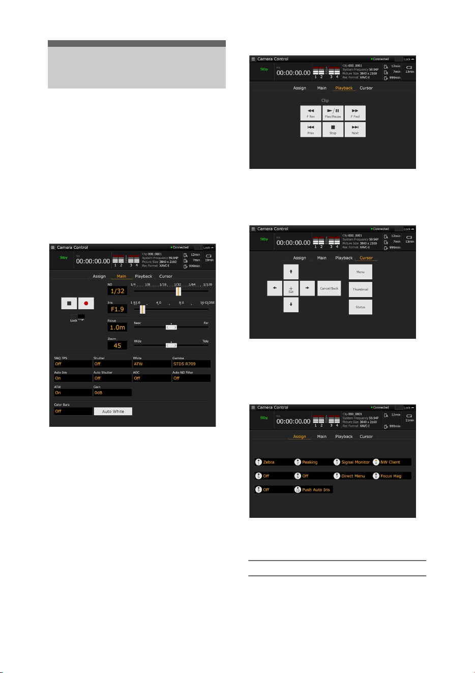
68
You can access the web remote control built into
the camcorder from a tablet or computer over a
network connection.
Using the web remote control allows you to
operate the camcorder remotely. You can start/
stop recording and adjust the recording settings
with a connected device. This function is useful
for setting the camcorder in a remote place, such
as the top of a crane, etc.
Camera Control screen
Main screen
• Status display
• Record start/stop button
• ND slider
•Iris slider
• Focus slider
• Zoom slider
• Shooting settings
S&Q FPS, Shutter, White, Gamma, Auto Iris, Auto
Shutter, AGC, Auto ND Filter, ATW, Gain, Color
Bars, Auto White
Playback screen
• Status display
• Playback operation buttons:
F Rev, Play/Pause, F Fwd, Prev, Stop, Next
Cursor screen
• Status display
• Cursor operation button, menu/status indication:
Up, Left, Set, Right, Down, Cancel/Back, Menu,
Status, Thumbnail
Assign screen
• Status display
• Assignable buttons:
Assignable buttons 1 to 10
Displaying the web remote control
1 Connect the camcorder and device via a
network connection (page 54).
Using Web Remote
Control
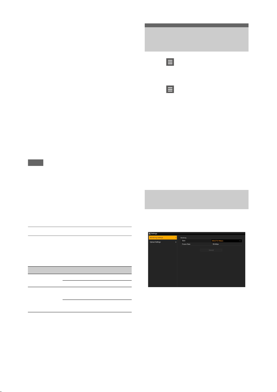
69
2 Launch a browser on the device, then
access “http://IP address of camcorder/
rm.html.”
Example: When the IP address is
192.198.122.1, input http://192.168.1.1/
rm.html in the address bar.
You can check the IP address of the
camcorder on the Network Status screen
(page 16).
3 Input the user name and password
(Network menu t Access
Authentication t User Name and
Password) in the browser.
When connection is successful, the web
remote control screen appears on the device.
You can then use the web remote screen to
operate the camcorder.
Button operation can be disabled by sliding
the Lock switch to the right.
Notes
• The web remote control screen may not match the
camcorder settings under the following circumstances.
If this occurs, reload the browser window.
If the camcorder is restarted while connected
If the camcorder is operated directly while
connected
If the device has been reconnected
If the browser forward/back buttons have been used
• The web remote control may not function if the
wireless signal strength becomes weak.
Web remote control compatible devices
You can use a tablet or computer to configure and
operate the camcorder. The supported devices,
OS, and browsers are shown in the following
table.
For details about devices supported using the
“Content Browser Mobile” application, contact
your Sony sales or service representative.
Tapping in the top left of the Camera
Control screen will display the screen selection
menu. Select Monitoring Settings to display the
Monitoring Settings screen.
Tapping in the top left of the Monitoring
Settings screen will display the setup menu for
tasks, such as file transfer.
Menu items
• Remote Control
Camera Control
• Monitoring
Monitoring Settings
• File Transfer
Slot A
Slot B
Slot SD/MS
Job List
Upload Settings
You can set the format when monitoring on a
device.
Size
Sets the picture size and bit rate of the video for
monitoring.
• 480×270(1Mbps)
• 480×270(0.5Mbps)
Frame Rate
Displays the frame rate of the video for
monitoring.
Device OS Browser
Tablet Android 6/7 Chrome
iOS 11 Safari
Computer Windows 7/8.1/
10
Chrome
macOS 10.12/
10.13
Safari
Web Remote Control
Menu
Video monitoring settings
(Monitoring Settings)
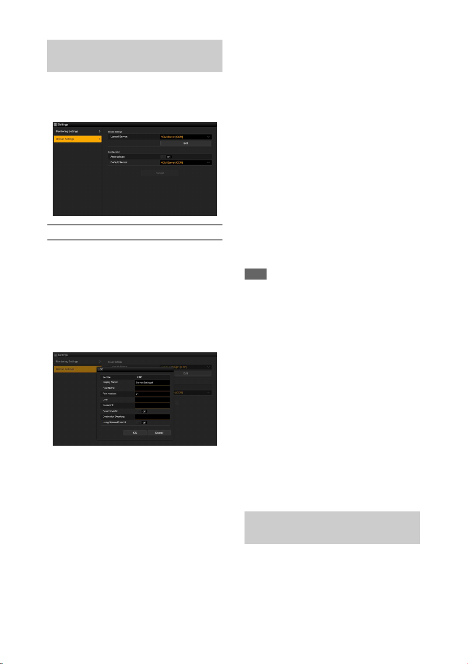
70
You can change the server settings for uploading
a proxy file or an original file that is recorded on
the camcorder.
Registering a destination server
Select one of the Server Settings1 to Server
Settings3 in the Upload Server list and tap Edit to
display the server setup screen, then set each item
to register a server.
You can also register a server using File Transfer
(page 62) in the Network menu.
A server configured here will be displayed in the
file transfer list on the Slot A, Slot B, and Slot SD/
MS screens when uploading a file.
Tap OK to apply the settings. Tap Cancel to
cancel the settings.
Service
Displays the server type.
“FTP”: FTP server
Display Name
Enter the name of the server to display in the list.
Host Name
Enter the address of the server.
Port Number
Enter the port number of the server to connect.
User
Enter the user name.
Password
Enter the password.
Passive Mode
Turn passive mode on/off.
Destination Directory
Enter the directory on the destination server.
Using Secure Protocol
Set whether to perform secure FTP uploading.
Setting to ON displays the certificate status.
To import or clear a certificate, tap Select
Function and select a task in the displayed menu.
•Load
Import a CA certificate.
* The certificate to be loaded must be in PEM format,
and should be written to the root directory of the SD
card with “certification.pem” file name.
•Clear
Clear the CA certificate.
• None
Do not load or clear a certificate.
Note
• Set the clock of the camcorder to the correct time
before importing a CA certificate.
Changing registered server settings
Select the server whose settings you want to
change on the Upload Settings screen, then tap
Edit. Change the settings on the screen for
changing the settings.
You can also set a server using File Transfer
(page 116) in the Network menu.
Uploading a proxy file automatically
Auto Upload On/Off
When Auto Upload On/Off is set to On and the
camcorder is connected to the Internet, the
camcorder automatically uploads a proxy file to
the server that is set as the default server using
Default Server after recording.
Default Server
Select the default destination file transfer server.
You can transfer original files recorded on an SxS
memory card or proxy files recorded on an SD
card, manage file transfer, and configure the file
transfer destination.
File transfer settings (Upload
Settings)
File transfer management (File
Transfer)
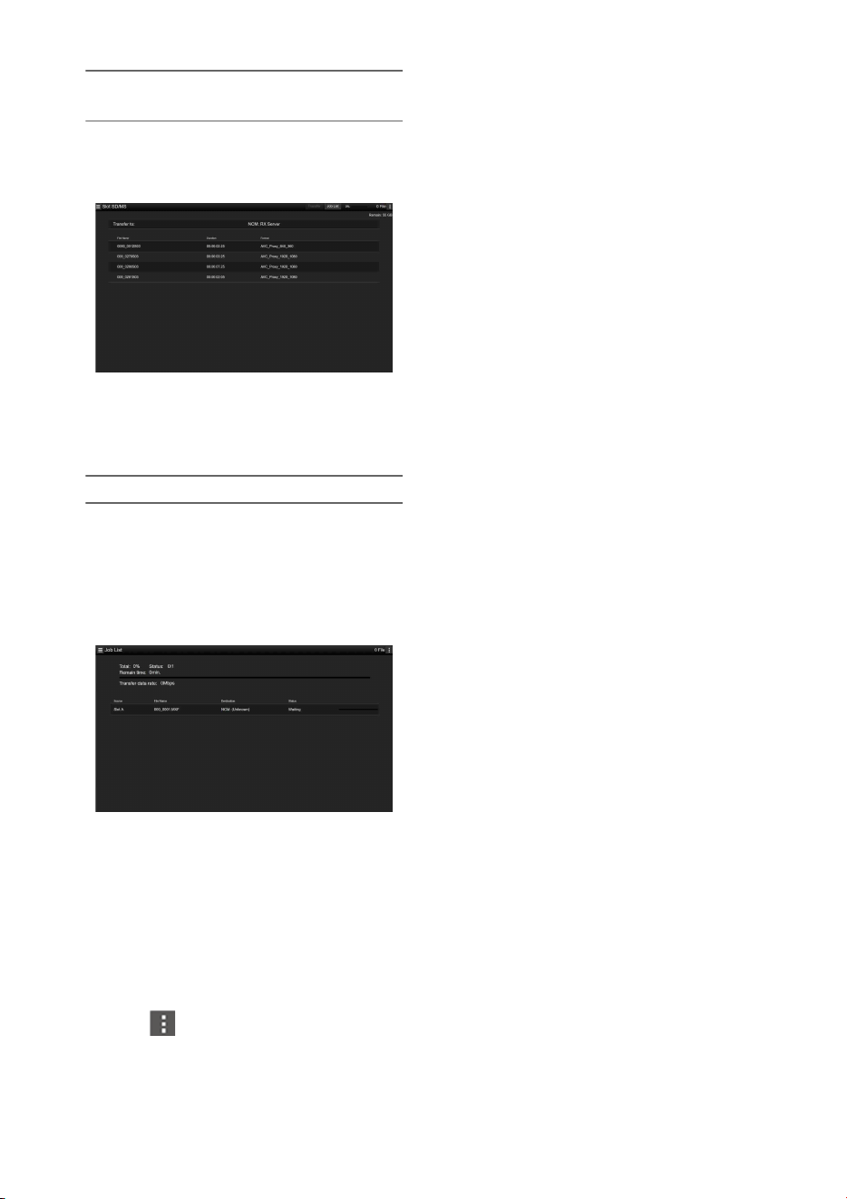
71
Transferring files (Slot A, Slot B, Slot SD/
MS)
Displays a list of clips recorded on media inserted
in slot A/slot B or a list of proxy files recorded on
media inserted in the UTILITY SD/MS slot.
You can select a displayed file to upload the file
to a server on the Internet. For details about
uploading files, see “Uploading a File”
(page 62).
Checking the file transfer (Job List)
You can check the list of the files to be uploaded,
the file that is being uploaded, cancel or start the
file upload, and delete the file from the file list.
The camcorder is compatible with the FTP
resume function (resume upload for a file whose
transfer was suspended).
• Total: Progress of all the files to be uploaded.
• Status: Progress of the file that is currently being
uploaded.
• Remain Time: Estimated remaining time for
uploading.
• Transfer data rate: Transfer rate indication.
To cancel or start uploading, or delete a file from
the file list
1 Select a file.
2 Tap at the upper right of the
screen, and select an item.
• Abort selected: Cancel uploading the selected
file.
• Delete from list: Delete the selected file from the
list.
• Start selected: Start uploading the selected file.
• Select All: Select all files in the list.
• Clear completed: Delete the list of uploaded files.
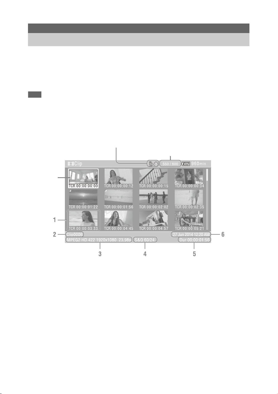
72
When you press the THUMBNAIL button (page 11), clips recorded on the SxS memory card are
displayed as thumbnails on the screen.
You can select a clip on the thumbnail screen and start playback of that clip. The playback picture can be
seen on the LCD/viewfinder screen and external monitors.
Pressing the THUMBNAIL button again closes the thumbnail screen and returns to the camera image.
Note
• Only the clips recorded in the currently selected recording format are displayed on the thumbnail screen. If an expected
recorded clip is not displayed, check the recording format. Take special note of this fact before formatting (initializing)
media.
Information for the clip at the cursor position is displayed at the bottom of the screen.
1. Thumbnail (index picture)
Displays the index picture of a clip. When a clip
is recorded, its first frame is automatically set as
the index picture.
Clip/frame information is displayed below the
thumbnail. You change the information
displayed using Customize View (page 78)
>Thumbnail Caption in the Thumbnail menu.
2. Clip name
Displays the name of the selected clip.
3. Recording video format
Displays the file format of the selected clip.
4. Special recording information
Displays the recording mode only if the clip was
recorded using a special recording mode.
For Slow & Quick Motion clips, the frame rate
is displayed on the right.
5. Clip duration
6. Creation date
Thumbnail Screen
Configuration of the Thumbnail Screen
Clip number/Total number of clips
Cursor
(yellow)
Currently selected SxS memory card indicator
(A lock icon is displayed if the card is protected.)

73
You can play recorded clips when the camcorder
is in recording standby (Stby) mode.
1 Insert an SxS memory card for
playback.
2 Press the PLAY/PAUSE button of the
playback control buttons.
3 Search for the desired clip by pressing
the PREV or NEXT button.
4 Press the PLAY/PAUSE button.
The playback image appears on the
viewfinder.
You can control playback by pressing the
following buttons.
PLAY/PAUSE button: Pauses playback. To
resume playback, press this button again.
F FWD button/F REV button: Plays fast. To
return to normal playback, press the PLAY/
PAUSE button.
STOP button: Stops playback or recording.
To select the first thumbnail
Press and hold the F REV button and press the
PREV button.
To select the last thumbnail
Press and hold the F FWD button and press the
NEXT button.
1 Press the V/v/B/b button or turn the
SEL/SET dial to move the cursor to the
thumbnail for the clip you want to play.
2 Press the SET button or SEL/SET dial.
Playback begins from the start of the selected
clip.
Notes
• There may be momentary picture breakup or still
image display at the boundary between clips. You
cannot operate the camcorder during this period.
• When you select a clip in the thumbnail screen and
begin playback, there may be momentary picture
breakup at the start of the clip. To start playback
without distortion, pause playback once after starting
it, press the PREV button of the playback control
buttons to return to the top of the clip, then restart
playback.
You can add shot marks to clips during playback
by pressing buttons the same way as used during
recording.
In a region where you want to insert shot
marks, press the assignable buttons
assigned with Shot Mark1 or Shot Mark2.
Notes
• Shot marks cannot be recorded when the SxS memory
card is write protected.
• Shot marks cannot be recorded at the start or end of a
clip.
In normal playback mode, you can monitor the
recorded audio signals through the built-in
speaker or connected headphones.
Connecting a set of headphones to the headphone
jack (page 10) cuts off the built-in speaker.
Adjust the volume using the VOLUME buttons
(page 11).
You can select the channel to monitor using
Audio Output (page 102) in the Audio menu.
Playing Clips
Playing recorded clips
Playing the selected and
subsequent clips in sequence
Adding shot marks during
playback (exFAT, UDF)
Monitoring audio during playback

74
The Thumbnail menu is used to protect/delete
clips, check properties, add/delete clip flags in a
clip, and other tasks.
The Thumbnail menu can be used only when a
thumbnail screen is displayed.
1 Press the THUMBNAIL button.
The thumbnail screen appears.
2 Press the MENU button.
The menu screen appears.
3 Select Thumbnail using the V/v/B/b
button or SEL/SET dial, and press the
SET button or SEL/SET dial.
To hide the Thumbnail menu, press the MENU
button again.
Select menu items and sub-items using the
following method.
Select an item or sub-item using the V/v/B/
b button or SEL/SET dial, and press the
SET button or SEL/SET dial.
Press the CANCEL/BACK button (page 10) to
return to the previous screen.
Notes
• When the SxS memory card is write-protected, some
operations are unavailable.
• Some items cannot be selected, depending on the state
when the menu was displayed.
Clip Operations
Thumbnail menu operations
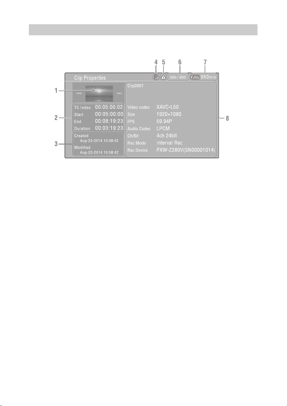
75
Select Display Clip Properties in the Thumbnail menu.
1. Image of the current clip
2. Timecode indicator
TC Index: Timecode of the displayed frame
Start: Timecode at the recording start point
End: Timecode at the recording end point
Duration: Duration of the clip
3. Creation date and modified date
4. Currently selected memory card
5. Media protect icon
6. Clip number/Total number of clips
7. Battery icon
8. Clip information
Clip name
Recording format
Special recording information
Recording device name
Displaying clip properties

76
You can protect a specified clip or all clips to
protect the clips from being deleted.
is added to the thumbnails of protected clips.
Clips can be protected on the thumbnail screen or
the filtered clip thumbnail screen (page 77).
Protecting a specific clip
1 Select Lock/Unlock Clip >Select Clip
>Execute in the Thumbnail menu.
The clip selection screen appears.
2 Select the clip to protect.
A check mark is attached to the selected clip.
3 Press the MENU button.
A confirmation screen appears.
4 Select Execute.
The clip is protected, and a completion
message appears.
5 Press the SET button or SEL/SET dial
to dismiss the message.
Protecting all clips
1 Select Lock/Unlock Clip >Lock All
Clips >Execute in the Thumbnail menu.
A confirmation screen appears.
2 Select Execute.
All clips are protected, and a completion
message appears.
3 Press the SET button or SEL/SET dial
to dismiss the message.
Unlocking all clips
1 Select Lock/Unlock Clip >Unlock All
Clips >Execute in the Thumbnail menu.
A confirmation screen appears.
2 Select Execute.
All clips are unlocked, and a completion
message appears.
3 Press the SET button or SEL/SET dial
to dismiss the message.
You can copy clips to another SxS memory card.
Clips are copied to destination SxS memory cards
using the same names as the original clips.
Notes
• If a clip with the same name already exists at the copy
destination SxS memory card, a one-digit number in
parentheses is added to the original name.
• The number in parentheses is the smallest number that
does not exist at the copy destination.
Examples: ABCD0002 t ABCD0002(1)
ABCD0002(1) t ABCD0002(2)
ABCD0005(3) t ABCD0005(4)
• For FAT file format, if the parenthetical numbers (1) to
(9) already exist at the copy destination, it is not
possible to copy any more clips under that name.
• For exFAT and UDF file formats, if the parenthetical
numbers (1) to (999) already exist at the copy
destination, because a clip has been copied more than
1000 times, it is not possible to copy any more clips
under that name.
• A message appears if there is not enough free space on
the copy destination SxS memory card. Exchange the
card for one with more free space.
• To copy an SxS memory card with multiple recorded
clips, it may not be possible to copy all clips even when
the SxS memory cards have the same capacity,
depending on the memory characteristics and usage of
the memory cards.
Copying a specific clip
1 Select Copy Clip >Select Clip >Execute
in the Thumbnail menu.
The clip selection screen appears.
2 Select the clip to copy.
A check mark is attached to the selected clip.
3 Press the MENU button.
A confirmation screen appears.
4 Select Execute.
The clip is copied, and a completion message
appears.
5 Press the SET button or SEL/SET dial
to dismiss the message.
Protecting clips (exFAT, UDF)
Copying clips

77
Copying all clips
You can copy all clips stored on the same SxS
memory card at the same time to another SxS
memory card.
1 Select Copy Clip > All Clips >Execute in
the Thumbnail menu.
A confirmation screen appears.
2 Select Execute.
All clips are copied, and a completion
message appears.
3 Press the SET button or SEL/SET dial
to dismiss the message.
You can delete clips from SxS memory cards.
Note
• Protected clips cannot be deleted. To delete, first
unlock the clip.
Deleting a specific clip
1 Select Delete Clip >Select Clip >Execute
in the Thumbnail menu.
The clip selection screen appears.
2 Select the clip to delete.
A check mark is attached to the selected clip.
3 Press the MENU button.
A confirmation screen appears.
4 Select Execute.
The clip is deleted, and a completion
message appears.
5 Press the SET button or SEL/SET dial
to dismiss the message.
Deleting all clips
1 Select Delete Clip > All Clips >Execute
in the Thumbnail menu.
A confirmation screen appears.
2 Select Execute.
All clips are deleted, and a completion
message appears.
3 Press the SET button or SEL/SET dial
to dismiss the message.
You can add clip flags (OK, NG, KEEP marks) to
clips to filter the display of clips based on the clip
flags on the filtered clip thumbnail screen
(page 77).
Adding a clip flag
1 Select the thumbnail for the clip to
which you want to add the clip flag.
2 Select Set Clip Flag >Add OK, Add NG,
or Add KEEP in the Thumbnail menu
for the type of clip flag to add.
The clip flag is added to the thumbnail of the
selected clip.
You can also assign Clip Flag OK, Clip Flag NG,
and Clip Flag Keep to assignable buttons
(page 40), and press the button to add a clip flag.
Deleting a clip flag
1 Select the thumbnail for the clip to
which you want to delete a clip flag.
2 Select Set Clip Flag >Delete Clip Flag in
the Thumbnail menu.
The clip flag for the selected clip is deleted.
Select Filter Clips > OK, NG, or KEEP
>Execute in the Thumbnail menu to filter
the clips by clip flags.
The clip screen appears showing the clips filtered
by the selected clip flag. This screen is referred to
as the filtered clip thumbnail screen.
Deleting clips
Adding/deleting clip flags (exFAT,
UDF)
Filtering the clips displayed using
the filtered clip thumbnail screen
(exFAT, UDF)

78
Selecting Filter Clips >All on the Thumbnail
screen cancels the filtering, and returns to the clip
thumbnail screen.
You can also switch using the DISPLAY button.
You can delete shot marks added to a clip.
You delete shot marks on the essence mark
thumbnail screen.
1 Select Thumbnail View >Essence Mark
Thumbnail in the Thumbnail menu,
and select the type of shot mark to
delete (Shot Mark1 or Shot Mark2).
The essence mark thumbnail screen appears.
2 Select the thumbnail of the frame with
the shot mark to delete.
3 Select Set Shot Mark >Delete Shot
Mark1 or Delete Shot Mark2 in the
Thumbnail menu.
The shot mark is deleted from the selected
frame.
When more than one essence mark (shot mark,
recording start mark) has been recorded in a clip,
you can display thumbnails for only those frames
with an added essence mark.
This screen is referred to as the essence mark
thumbnail screen.
Select Thumbnail View >Essence Mark
Thumbnail in the Thumbnail menu to select
the type of essence mark for filtering.
All: All frames with added essence marks
Rec Start: Frames with a recording start mark
and the first frame of clips that do not have a
recording start mark
Shot Mark0 to Shot Mark9: Frames with each
shot mark
The essence mark thumbnail screen appears,
filtered by the selected essence mark.
If a clip is recorded using planning metadata that
defines names for shot mark 0 to shot mark 9, the
selection options in the list are displayed by the
defined names.
You can change the clip/frame information
displayed below the thumbnail.
Select Customize View >Thumbnail
Caption in the Thumbnail menu and select
the information to display.
Date Time: Date and time the clip was created
and last modified.
Time Code: Timecode
Duration: Duration
Sequential Number: Thumbnail number
You can set the frame selected on the essence
mark thumbnail screen as the index picture for the
clip.
1 On the essence mark thumbnail screen,
select the thumbnail for the frame you
want to set as the index picture.
2 Select Set Index Picture in the
Thumbnail menu.
The selected frame is set as the index picture
of the clip.
Deleting shot marks (exFAT, UDF)
Filtering clips (frames) using the
essence mark thumbnail screen
(exFAT, UDF)
Changing the information
displayed on the thumbnail screen
Changing the index picture of a
clip

79
To display recorded/playback pictures on an
external monitor, select the camcorder output
signal and use an appropriate cable for the
monitor to be connected.
You can also connect recording devices, such as a
VTR, and record the output signal from the
camcorder.
You can display the same information that is
visible in the viewfinder, such as status
information and menus, on an external monitor.
Set Output Display (page 102) in the Video menu
to On for the corresponding type of signal to
output to the monitor.
SDI OUT connector (BNC type)
Set the on/off setting of the output, and the output
format in the Video menu (page 102).
Use a commercially available 75 Ω coaxial cable
for connection.
Note
• Check that the connection between the camcorder and
the external device is grounded before turning the
devices on.
(It is recommended that the camcorder and external
device be turned on after connecting the 75 Ω coaxial
cable.)
If the external device must be connected to the
camcorder while the camcorder is on, connect the 75 Ω
coaxial cable to the external device first and then
connect it to the camcorder.
To start recording on the camcorder and external
device simultaneously
With SDI signal output enabled, set SDI/HDMI
Rec Control (page 102) >Setting in the Video
menu to On to enable output of a REC trigger
signal to the external device connected to the SDI
OUT connector. This will synchronize recording
on the external device with the camcorder.
Note
• If a connected external device does not support a REC
trigger signal, the device cannot be operated.
HDMI OUT connector (Type A connector)
Set the on/off setting of the output, and the output
format in the Video menu (page 102).
Use a commercially available high-speed HDMI
cable for connection.
GENLOCK IN/VIDEO OUT connector (BNC
type)
The connector can output the HD-Y signal, HD-
Sync Signal, or the down-converted SD analog
composite signal for the monitor by changing the
Output Format setting in the Video menu.
Use a commercially available BNC cable for
connection.
For details, see “Video formats and output
signals” (page 132).
Multi/Micro USB connector
2-channel audio signals can be output using the
VMC-15MR2 AV cable (sold separately).
External Device Connection
Connecting External Monitors and Recording Devices
80
When multiple units of the camcorder are used in
the same shooting location, recording can be
synchronized with a specific reference signal, and
the timecode can be matched among all the units.
Synchronizing the phase of the video
signals (genlock)
Genlock operation is enabled by supplying a
reference signal to the GENLOCK IN/VIDEO
OUT connector (page 9) of the camcorder.
The reference signals that can be used vary
depending on the system frequency of the
selected recording format.
Notes
• Both video signal and timecode signal need to be input
when the selected recording format is 1280×720 60P.
• If the reference signal is unstable, genlock cannot be
achieved.
• The subcarrier is not synchronized.
Locking to the timecode of another
device
Set the unit that supplies the timecode to a mode
in which the timecode output keeps running (such
as Free Run or Clock).
1 Set Timecode in the TC/UB menu as
follows:
Mode: Preset
Run: Free Run
2 Press the DURATION/TC/U-BIT
button (page 11) so that the timecode is
displayed on the screen.
3 Confirm that the IN/OUT switch
(page 9) is set to IN, then supply an HD
or SD reference video signal to the
GENLOCK IN/VIDEO OUT connector
and the reference timecode to the TC
connector.
The built-in timecode generator of your
camcorder locks to the reference timecode, and
“Ext LK” is displayed on the screen.
Once about ten seconds have elapsed after the
timecode locks, the external lock state is
maintained even if the external reference
timecode source is disconnected.
Notes
• Check that the supplied reference timecode and the
reference video signal are in a phase relationship that
complies with the SMPTE timecode standard.
• When operating with external lock, the timecode
instantly acquires lock with the external timecode and
the external timecode value appears in the data display
area. However, do not start recording immediately.
Wait for a few seconds until the timecode generator
stabilizes before recording.
• If the frequency of the reference video signal and the
frame frequency on the camcorder are not the same,
lock cannot be acquired and the camcorder will not
operate properly. If this occurs, the timecode will not
acquire successful lock with the external timecode.
• If the external timecode source is disconnected, the
timecode may shift by one frame per hour with respect
to the reference timecode.
External Synchronization
System frequency of
recording format
Supported input
reference signals
59.94P 1920×1080 59.94i
720×486 59.94i
1280×720 59.94P
29.97P 1920×1080 59.94i
720×486 59.94i
23.98P 1920×1080 47.95i
(23.98PsF)
59.94i 1920×1080 59.94i
720×486 59.94i
50P 1920×1080 50i
720×576 50i
1280×720 50P
25P 1920×1080 50i
720×576 50i
50i 1920×1080 50i
720×576 50i

81
To release external lock
Change the Timecode setting in the TC/UB menu
or set the camcorder to STANDBY.
External synchronization is also released if the
system frequency is changed and when you start
recording in a special recording mode (Slow &
Quick Motion or Interval Rec).
Synchronizing the timecode of another
unit to the timecode of your camcorder
1 Set the timecode of the camcorder using
Timecode (page 36) in the TC/UB menu.
2 Check that the TC IN/OUT switch
(page 9) is set to the OUT position, and
connect the TC connector and
GENLOCK IN/VIDEO OUT connector
(page 9) to the timecode input and
reference signal input, respectively, of
the device you want to synchronize.
Connect the camcorder to a computer using the
supplied USB cable, and insert a memory card in
the slot. The memory card is recognized as a
computer extension drive.
When two memory cards are mounted in the
camcorder, they are recognized as two
independent extended drives by the computer.
Notes
• The camcorder does not work on the bus power from
the computer. Prepare a power source separately.
• The camcorder is not recognized as an extension drive
in the following cases.
During recording (including special recording
modes)
During playback (including high-speed playback
and when paused)
During thumbnail screen display
When formatting (initializing) media
When restoring memory cards or updating
management files (including during confirmation
before execution)
During streaming
During connection in network client mode
1 Connect the Multi/Micro USB
connector of the camcorder to the
computer using a USB cable.
2 Set the ON/STANDBY switch to ON.
A message prompting you to confirm that
you wish to enable the USB connection is
displayed on the LCD/viewfinder screen.
Note
• If the confirmation message disappears,
disconnect and then reconnect the USB cable.
The confirmation message is not displayed during
recording/playback/thumbnail screen display.
3 Select Execute using the V/v/B/b button
or SEL/SET dial.
4 On Windows, check that the card is
added as a removable disk in the “My
Computer” window.
On Macintosh, check that a folder
Managing/Editing Clips
on a Computer
Connecting using a USB cable

82
called “NO NAME” or “Untitled”
(editable) is created on the Desktop.
Notes
• Do not perform the following operations if the access
lamp is lit red.
Turning the power off or disconnecting the power
cord
Removing the SxS memory card
Disconnecting the USB cable
• When removing an SxS memory card from a
Macintosh, do not select “Card Power Off” from the
SxS memory card icon displayed on the menu bar.
• Operation is not guaranteed with all computers.
Using application software
To copy clips to the local disk of your computer,
the dedicated application software must be
downloaded and installed on your computer. For
details about downloading software, see
“Software Downloads” (page 149).
Although the data regarding recorded materials
are stored over multiple files and folders, you can
easily handle the clips without considering its
data and directory structure, by using the
dedicated application software.
Note
• If you perform operations on clips, such as copying the
clips on the SxS memory card using Explorer
(Windows) or Finder (Macintosh), the subsidiary data
contained by the clips may not be maintained.
Using a nonlinear editing system
In a nonlinear editing system, editing software
(option) that supports the formats recorded by the
camcorder is required.
Use dedicated application software to save the
clips you want to edit on the HDD of the
computer beforehand.
When an external HDD or USB media is
connected to the USB 3.0 (HOST) connector of
the camcorder, you can copy clips from the
recording media inserted in an SxS memory card
slot to the external HDD or USB media.
Copying clips to USB media
1 Select USB >Select Folder (page 110) in
the Media menu.
2 Select the copy destination folder from
the folder list, and press the SET button
or SEL/SET dial.
You can also select New on the screen to
create a new folder.
Note
• If a folder is not specified, a folder is
automatically created with a folder name the
same as the creation date of the first clip to be
copied, and clips are copied to that folder.
3 Select USB >Copy to USB (page 110) in
the Media menu, insert the target
recording media to copy, and select the
SxS memory card slot.
Media(A) to USB: Copy all clips from the
recording media inserted in slot A.
Media(B) to USB: Copy all clips from the
recording media inserted in slot B.
Media(A)(B) to USB: Copy all clips from
the recording media inserted in slot A and
slot B.
Note
• When a copy destination folder is specified in
step 2 and Media(A)(B) to USB is selected, slot A
clips are copied to the specified destination
folder. Slot B clips are copied to a folder that is
automatically created with a folder name the
same as the creation date of the first clip.
4 Select Execute using the V/v/B/b button
or SEL/SET dial, and press the SET
button or SEL/SET dial.
All clips on the target recording media are
copied to the USB media.
Note
• If a clip with the same file name as the clip to
copy already exists in the destination folder, the
clip is not copied.
Displaying a list of clips on an external
HDD/USB media
You can display a list of the clips on an external
HDD/USB media using USB >View Clip List
(page 110) in the Media menu.
Connecting an external HDD/USB
media
83
Renaming a folder on an external HDD/
USB media
1 Select USB >Rename Folder (page 110)
in the Media menu.
2 Select the folder to rename from the
folder list, and press the SET button or
SEL/SET dial.
A file name input screen appears.
3 Enter a folder name, and select Done.
The folder is renamed.
Checking for copy read errors
You can check for read errors after writing clips
by setting USB >Error Check (page 110) in the
Media menu to On.
Formatting (initializing) an external
HDD/USB media
1 Select USB >Format USB (page 110) in
the Media menu.
2 Select Execute using the V/v/B/b button
or SEL/SET dial, and press the SET
button or SEL/SET dial.
Initialization (formatting) begins.
3 When the formatting is completed, a
message appears. Select OK.
Checking the remaining capacity on an
external HDD/USB media
The free space on an external HDD/USB media is
displayed in the Media Remain row on the screen
displayed when USB in the Media menu is
selected.
About power supply to an external HDD/
USB media
Power is supplied to an external HDD/USB
media from the USB 3.0 (HOST) connector
automatically when performing an operation in
the USB menu item in the Media menu.
However, power supply is not started under the
following conditions, even when performing an
operation in the USB menu item in the Media
menu. To start the supply of power, perform the
solution shown in the table.
Notes
• Clips on an external HDD/USB media cannot be
copied to recording media inserted in an SxS memory
card slot.
• Clips cannot be recorded while power is supplied to the
USB 3.0 (HOST) connector. To start recording clips,
terminate the USB menu item operation in the Media
menu.
State Solution
During clip recording,
playback, thumbnail display,
proxy recording, formatting/
restoring media,
management file update,
software update, camcorder
resetting, network reset,
computer connecting,
confirmation screen display,
streaming
Terminate the previous
operation.
Insufficient supply voltage Change the battery or
replace the input power
supply.
Rec Format >File System is
not set to exFAT
Set to exFAT.
Network Client Mode is On Set Network Client
Mode to Off.

84
Press the MENU button to display the setup menu
on the LCD screen/viewfinder to specify various
items for shooting, recording, and playback
(menu can also be displayed on an external
monitor). The setup menu comprises the
following menus.
User Menu: Menu with items configured by the
user (edit using Edit User Menu).
Edit User Menu menu: Menu for editing User
menu items.
Camera menu: Contains settings related to
shooting.
Paint menu: Contains settings related to picture
quality.
Audio menu: Contains settings related to audio.
Video menu: Contains settings related to video
output.
LCD/VF menu: Contains settings to the LCD
screen and viewfinder display.
TC/UB menu: Contains settings related to
timecode and user bits.
Recording menu: Contains settings related to
recording.
Thumbnail menu: Contains settings related to
thumbnail display.
Media menu: Contains settings related to
media.
File menu: Contains settings related to files.
Network menu: Contains settings related to
networks.
System menu: Contains settings related to the
system.
Menu Display and Settings
Setup Menu Configuration and Hierarchy
Setup menu hierarchy
MENU
User Base Setting
HDR Setting
Rec Format
S&Q Motion
Picture Cache Rec
Simul Rec
4K & HD (Sub) Rec
Proxy Rec
Output Format
Assignable Button
Delete Clip
Wireless LAN
Wired LAN
Modem
Format Media
Menu Settings
Edit User Menu
Edit User Menu Add Item
Customize Reset
Camera Focus
ND Filter
Gain
Shutter
Auto Exposure
Color Bars
Flicker Reduce
Flash Band Reduce
Handle Zoom
Auto Black Balance
Auto FB Adjust
Video Light Set
Paint HDR Paint Setting
White
White Setting
Offset White
Black
Gamma
Black Gamma
Low Key Saturation
Saturation Mode
Noise Suppression
Knee
White Clip
Detail(QFHD)
Detail(HD)
Detail(SD)
Skin Detail
Aperture
Matrix
Multi Matrix
Maintenance
Audio Audio Input
Audio Output

85
Video Output On/Off
Output Format
Output Display
SDI/HDMI Rec Control
Down Converter
LCD/VF LCD Setting
VF Setting
Peaking
Marker
Zebra
Gamma Display Assist
Display On/Off
TC/UB Timecode
Users Bit
HDMI TC Out
Recording S&Q Motion
Interval Rec
Picture Cache Rec
Clip Continuous Rec
Simul Rec
4K & HD (Sub) Rec
Proxy Rec
Rec Review
Thumbnail Display Clip Properties
Set Shot Mark
Set Clip Flag
Lock/Unlock Clip
Delete Clip
Copy Clip
Copy Sub Clip
Set Index Picture
Thumbnail View
Filter Clips
Customize View
Media Update Media
Format Media
USB
Clip Naming
Planning Metadata
File User File
All File
Scene File
Network Access Authentication
Wireless LAN
AP Mode Settings
ST Mode Settings
Wired LAN
Modem
Network Client Mode
File Transfer
Streaming
Network Reset
System Base Setting
HDR Setting
Rec Format
Assignable Button
Tally
Language
Clock Set
Hours Meter
GPS
Battery Alarm
DC Voltage Alarm
Menu Settings
Fan Control
All Reset
Version
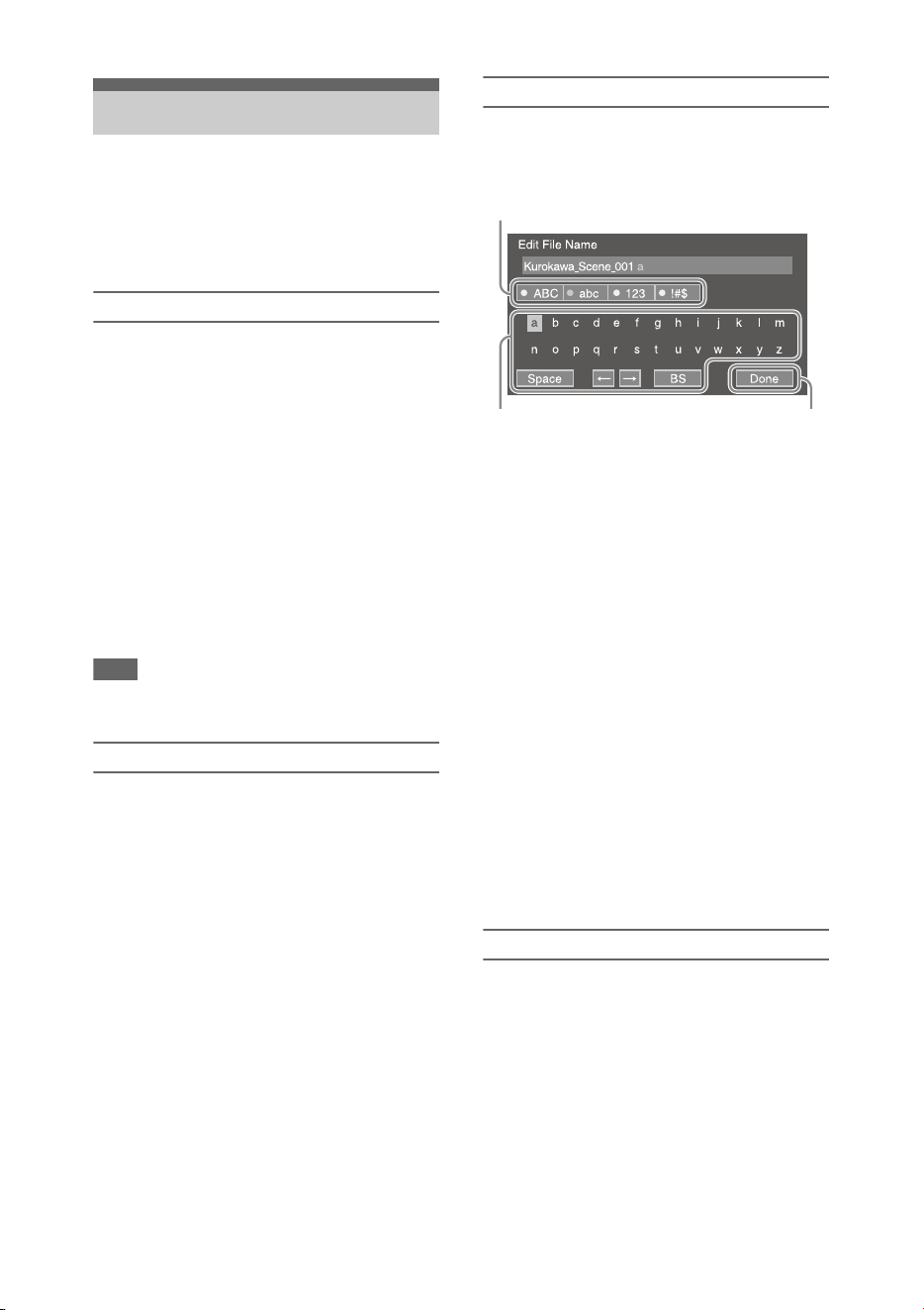
86
Press the MENU button to display the setup menu
on the LCD screen/viewfinder to specify various
items for shooting, recording, and playback
(menu can also be displayed on an external
monitor).
Menu controls
MENU button (page 10)
Turn menu mode on/off for setup menu operation.
SEL/SET dial (page 10)
Turn the dial to move the cursor up/down to select
menu items or settings.
Press the SEL/SET dial to apply the selected item.
CANCEL/BACK button (page 10)
Press to return to the previous menu. An
uncompleted change is canceled.
V/v/B/b/SET button
Press the V/v/B/b buttons to move the cursor up/
down/left/right to select menu items or settings.
Press the SET button to apply the selected item.
Note
• The setup menu cannot be operated when in focus
magnifier screen mode (page 29).
Setting menu items
Move the cursor to the desired item by pressing
the V/v/B/b button or turning the SEL/SET dial,
and press the SET button or SEL/SET dial to
apply the setting.
• The menu item selection area can show up to 9
lines. If the available options for an item cannot
be displayed at the same time, scroll the display
by moving the cursor up/down.
• For sub-items with a large settings range (for
example, –99 to +99), the settings area is not
displayed. The current setting is highlighted to
indicate that the value can be changed.
• Selecting Execute for a function will execute
the corresponding function.
• Selecting an item that requires confirmation
before execution will temporarily hide the menu
and display a confirmation message. Check the
message, and then select whether to execute or
cancel the function.
Entering a character string
When you select an item, such as a file name,
which requires character entry, the character
entry screen appears.
1 Turn the SEL/SET dial to select a
character type, then press the dial.
ABC: Uppercase alphabetic characters
abc: Lowercase alphabetic characters
123: Numeric characters
!#$: Special characters
2 Select a character from the selected
character type, then press the dial.
The cursor moves to the next field.
Space: Enters a space character at the cursor
position.
B/b: Moves the position of the cursor.
BS: Deletes the character on the left of the
cursor (backspace).
3 When finished, select Done and press
the dial.
The character string is confirmed and the
character entry screen disappears.
Locking and unlocking the menu
You can lock the setup menu so that only the User
menu is displayed.
Locking the menu
1 Press and hold the SEL/SET dial and
press the MENU button.
2 Select Menu Settings >User Menu with
Lock in the System menu.
Setup Menu Operations
1
23
87
Note
• When only the MENU button is pressed to
display the normal setup menu, User Menu Only
is displayed under Menu Settings in the System
menu. Press and hold the SEL/SET dial and press
the MENU button to display User Menu with
Lock.
3 Set to On, and press the SET button or
SEL/SET dial.
The LCD/viewfinder screen display switches
to the passcode number input screen.
4 Enter an arbitrary number.
Enter a 4-digit number in the range 0000 to
9999. The default value is 0000.
Enter a number and press the SET button or
SEL/SET dial to move the cursor to the next
digit.
When all digits have been entered, move the
cursor to SET.
5 Press the SET button or SEL/SET dial.
The entry is applied.
A confirmation message appears, and the
screen switches to the User menu display.
Notes
• If the menu is locked without registering setup menu
items from the following tables in the User menu,
those functions cannot be assigned to assignable
buttons.
• If those functions were already assigned to assignable
buttons, the assignable setting is forcibly disabled at
the point when the menu is locked.
Unlocking the menu
1 Press and hold the SEL/SET dial and
press the MENU button.
2 Select Menu Settings >User Menu with
Lock in the System menu.
Setup menu item Assignable button
selection options
Camera >Focus >Face
Detection AF
Face Detection AF
Camera >Gain >Gain
<Turbo>
Turbo Gain
Camera >Auto Exposure
>Level
Auto Exposure Level
Camera >Auto Exposure
>Mode
Spotlight
Camera >Auto Exposure
>Mode
Backlight
Camera >Auto Exposure
>Auto ND Filter
Auto ND Filter
Camera >Auto Exposure
>AGC
AGC
Camera >Auto Exposure
>Auto Shutter
Shutter
Camera >Color Bars
>Setting
Color Bars
Camera >Flash Band Reduce
>Setting
Flash Band Reduce
Camera >Handle Zoom
>Setting
Handle Zoom
Paint >White >Preset White Preset White Select
LCD/VF >VF Setting >Color
Mode
VF Mode
LCD/VF >Peaking >Setting Peaking
LCD/VF >Marker >Setting Marker
LCD/VF >Zebra >Setting Zebra
LCD/VF >Gamma Display
Assist >Setting
Gamma Display Assist
LCD/VF >Display On/Off
>Lens Info
Lens Info
LCD/VF >Display On/Off
>Video Signal Monitor
Video Signal Monitor
Recording >S&Q Motion
>Setting
S&Q Motion
Recording >Picture Cache
Rec >Setting
Picture Cache Rec
Recording >Clip Continuous
Rec >Setting
Clip Continuous Rec
Recording >Rec Review
>Setting
Rec Review
Thumbnail >Set Shot Mark
>Add Shot Mark1
Shot Mark1
Thumbnail >Set Shot Mark
>Add Shot Mark2
Shot Mark2
Thumbnail >Set Clip Flag
>Add OK
Clip Flag OK
Thumbnail >Set Clip Flag
>Add NG
Clip Flag NG
Thumbnail >Set Clip Flag
>Add KEEP
Clip Flag Keep
Network >Wireless LAN
>NFC
NFC
Network >Network Client
Mode >Setting
Network Client Mode
Network >File Transfer
>Auto Upload (Proxy)
Auto Upload (Proxy)
Network >Streaming
>Setting
Streaming
User User Menu
Setup menu item Assignable button
selection options

88
Note
• When only the MENU button is pressed to
display the normal setup menu, User Menu Only
is displayed under Menu Settings in the System
menu. Press and hold the SEL/SET dial and press
the MENU button to display User Menu with
Lock.
3 Set to Off, and press the SET button or
SEL/SET dial.
The LCD/viewfinder screen display switches
to the passcode number input screen.
4 Enter the passcode number used to lock
the menu.
Enter a number and press the SET button or
SEL/SET dial to move the cursor to the next
digit.
When all digits have been entered, move the
cursor to Set.
5 Press the SET button or SEL/SET dial.
The entry is applied.
If the entered passcode number matches the
passcode number used to lock the menu, the
menu is unlocked and the menu is displayed.
Notes
• If the entered passcode number does not match the
passcode number used to lock the menu, the menu is
not unlocked.
• It is recommended that you leave a record of the
passcode nearby, just in case it is forgotten. If you do
forget the passcode number, contact your Sony service
representative.
You can edit the User menu, such as adding
items, deleting items, and rearranging items, to
make the User menu more useful using Edit User
Menu.
Adding items and sub-items
1 Select Edit User Menu >Add Item in the
User menu.
The items that can be added are displayed.
2 Select an item to add.
A screen for selecting sub-items to add
appears.
3 Select a sub-item to add.
Place a check mark in the All checkbox to
add all sub-items.
Place a check mark in the individual
checkboxes to specify which sub-items to
add.
4 Select OK, and press the SET button or
SEL/SET dial.
The item/sub-item(s) are added.
Note
• The same item or sub-item cannot be registered twice.
Also, the name of the item or sub-item cannot be
changed.
Editing sub-items
You can specify the sub-items to display.
1 Select Edit User Menu in the User
menu, and select the item to edit.
The edit function list appears.
2 Select Edit Sub Item.
The Edit Sub Item screen appears.
All sub-items are checked when the screen is
first opened (function to display all sub-
items).
Remove the check marks for the sub-items
you do not want to display in the User menu.
3 Select OK, and press the SET button or
SEL/SET dial.
Editing is completed.
Deleting an item
1 Select Edit User Menu in the User
menu, and select the item to delete.
The edit function list appears.
2 Select Delete.
The item is deleted.
Moving an item
1 Select Edit User Menu in the User
menu, and select the item to move.
The edit function list appears.
Editing the User menu

89
2 Select Move.
The item to move is highlighted, and a
triangle mark and line indicate the
destination position.
3 Move the triangle mark and line to the
destination of the item, and press the
SET button or SEL/SET dial.
The item is moved.
Restoring the User menu to factory
default state
1 Select Edit User Menu >Customize
Reset in the User menu.
The Customize Reset screen appears.
2 Select Reset, and press the SET button
or SEL/SET dial.
A confirmation screen appears.
3 Select Execute, and press the SET
button or SEL/SET dial.
The User menu is restored to the factory
default state.

90
This section describes the function and settings of the items in each menu.
Factory default settings are shown in bold (for example,
18dB).
Setup Menu List
User menu
User
Factory registered items Description
Base Setting
System >Base Setting item
HDR Setting
System >HDR Setting item
Rec Format
System >Rec Format item
S&Q Motion
Recording >S&Q Motion item
Picture Cache Rec
Recording >Picture Cache Rec item
Simul Rec
Recording >Simul Rec item
4K & HD (Sub) Rec
Recording >4K & HD (Sub) Rec item
Proxy Rec
Recording >Proxy Rec item
Output Format
Video >Output Format item
Assignable Button
System >Assignable Button item
Delete Clip
Thumbnail >Delete Clip item
Wireless LAN
Network >Wireless LAN item
Wired LAN
Network >Wired LAN item
Modem
Network >Modem item
Format Media
Media >Format Media item
Menu Settings
System >Menu Settings item
Edit User Menu
Displays the Edit User Menu screen.
Edit User Menu menu
Edit User
Menu
Item Sub-items and Settings Description
Add Item
– Adds items and sub-items.
Customize
Reset
Reset Restores the User menu to factory default state.
Items displayed
when registered
item is selected
Delete Deletes an item.
Move Moves an item.
Edit Sub Item Edits a sub-item.

91
Camera menu
Camera
Item Sub-items and Settings Description
Focus
Face detection AF
settings
Face Detection AF
Face Only AF /
Face Priority AF / Off
Enables/disables face detection AF.
ND Filter
ND filter settings
Preset1
1/128 / 1/64 / 1/32 / 1/16 /
1/8 / 1/4
Sets the preset 1 value of the ND filter.
Preset2
1/128 / 1/64 / 1/32 / 1/16 /
1/8 / 1/4
Sets the preset 2 value of the ND filter.
Preset3
1/128 / 1/64 / 1/32 / 1/16 /
1/8 / 1/4
Sets the preset 3 value of the ND filter.
Gain
Gain settings
Gain<L>
18dB / 15dB / 12dB / 9dB / 6dB
/ 3dB / 0dB / –3dB
Sets the gain when the GAIN switch is set to the L position.
Gain<M>
18dB / 15dB / 12dB / 9dB /
6dB / 3dB / 0dB / –3dB
Sets the gain when the GAIN switch is set to the M position.
Gain<H>
18dB / 15dB / 12dB / 9dB /
6dB / 3dB / 0dB / –3dB
Sets the gain when the GAIN switch is set to the H position.
Gain <Turbo>
42dB / 18dB / 15dB /
12dB / 9dB / 6dB / 3dB / 0dB /
–3dB
Sets the gain value when an assignable button assigned with
the Turbo Gain function is pressed.
High Sensitivity Mode
On / Off
Turns high sensitivity mode on/off.
Shockless Gain
On / Off
Turns the shockless gain function on/off.

92
Shutter
Electronic shutter
operating
condition settings
Mode
Speed / Angle
Selects the operating mode of the electronic shutter.
Used for shooting fast-moving subjects clearly. Selects the
mode for setting the shutter speed in seconds (Speed) or as a
shutter angle (Angle).
Shutter Speed
64F, 32F, 16F, 8F, 7F, 6F, 5F,
4F, 3F, 2F, 1/24, 1/25, 1/30,
1/32, 1/33, 1/40, 1/48, 1/50,
1/60, 1/96, 1/100, 1/120, 1/125,
1/250, 1/500, 1/1000, 1/2000,
1/4000, 1/8000
Sets the shutter speed when Speed mode is selected. The
available settings vary depending on the frame frequency of
the selected video format.
Shutter Angle
64F / 32F / 16F / 8F / 7F /
6F / 5F / 4F / 3F / 2F /
360.0° / 300.0° / 270.0° /
240.0° / 216.0° / 210.0° /
180.0° / 172.8° / 150.0° /
144.0° / 120.0° / 90.0° / 86.4° /
72.0° / 45.0° / 30.0° / 22.5° /
11.25° / 5.6°
Sets the shutter angle when Angle mode is selected.
ECS
On / Off
Turns ECS mode on/off.
Used for shooting without scrolling horizontal bars appearing
on the LCD/viewfinder screen.
ECS Frequency
8000 to 23.99
(NTSC area: 60.00, PAL area:
50.00)
Sets the ECS frequency when ECS mode is selected. The
available settings vary depending on the frame frequency of
the selected video format.
Auto Exposure
Brightness
automatic
exposure settings
Level
+3.0 / +2.75 / +2.5 / +2.25 /
+2.0 / +1.75 / +1.5 / +1.25 /
+1.0 / +0.75 / +0.5 / +0.25 /
±0 / –0.25 / –0.5 / –0.75 /
–1.0 / –1.25 / –1.5 / –1.75 /
–2.0 / –2.25 / –2.5 / –2.75 /
–3.0
Sets the compensation level.
Mode
Backlight / Standard /
Spotlight
Sets the control mode.
Backlight: Backlight mode (mode for reduced darkening of a
subject when the subject is backlit)
Standard: Standard mode
Spotlight: Spotlight mode (mode for reduced blown out
highlights when subject is lit by spotlighting)
Speed
–99 to +99 (±0)
Sets the control speed.
Auto ND Filter
On / Off
Turns the ND filter density auto adjustment function on/off.
AGC
On / Off
Turns the AGC (auto gain control) function on/off.
AGC Limit
0dB / 3dB / 6dB / 9dB / 12dB /
15dB / 18dB
Sets the maximum gain of the AGC function.
AGC Point
F2.8 / F4 / F5.6
Sets the F-stop value of the iris where AGC operation starts
when the AGC function is On.
Camera
Item Sub-items and Settings Description
93
Auto Exposure
Brightness
automatic
exposure settings
Auto Shutter
On / Off
Turns the auto shutter control function on/off.
A.SHT Limit
1/100 / 1/150 / 1/200 /
1/250 / 1/2000
Sets the fastest shutter speed of the auto shutter function.
A.SHT Point
F5.6 / F8 / F11 / F16
Sets the F-stop value of the iris where auto shutter operation
starts.
Clip High light
On / Off
Turns the function that ignores brightest areas to provide a
flatter response at high luminance on/off.
Detect Window
1 / 2 / 3 / 4 / 5 / 6 / Custom
Sets the light meter range for automatically adjusting the
exposure according to the brightness of the subject. (Not
available when adjusting exposure manually)
Detect Window Indication
On / Off
Turns the Detect Window function on/off.
Average Peak Level Ratio
–99 to +99 (±0)
Sets the ratio between the average value and the peak of the
video signal used for Auto Exposure detection.
Custom Width
40 to 999 (500)
Sets the width of the Detect Window.
Custom Height
70 to 999 (500)
Sets the height of the Detect Window.
Custom H Position
–479 to +479 (±0)
Sets the horizontal position of the Detect Window.
Custom V Position
–464 to +464 (±0)
Sets the vertical position of the Detect Window.
Color Bars
Color bar settings
Setting
On / Off
Turns the color bars on/off.
Type
ARIB / 100% / 75% / SMPTE
Selects the type of color bars.
Flicker Reduce
Flicker correction
settings
Mode
Auto / On / Off
Sets the flicker correction mode.
Frequency
50Hz / 60Hz
(NTSC area: 60.00, PAL area:
50.00)
Sets the frequency of the power source supplying the lighting
that is causing the flicker.
Flash Band
Reduce
Flashband
correction settings
Setting
On / Off
Turns the flashband reduction function on/off. It reduces
blown out highlights at either the top or the bottom of the
image when shooting with a flash for a still camera.
Handle Zoom
Handle zoom
speed settings
Setting
Off / Low / High / Variable
Sets the speed of the handle zoom.
(Enabled when the handle zoom switch is set to FIX.)
High
1 to 8 (8)
Sets the zoom speed of the handle zoom lever when High
handle zoom speed is selected.
Low
1 to 8 (3)
Sets the zoom speed of the handle zoom lever when Low
handle zoom speed is selected.
Auto Black
Balance
Auto black balance
settings
Auto Black Balance
Execute / Cancel
Executes the auto black balance function.
Notes
• Cannot be set during recording or color bar display.
• Cannot be set when in Interval Rec mode, frame recording
mode, or slow shutter mode.
Camera
Item Sub-items and Settings Description
94
Auto FB
Adjust
Auto focal length
(flangeback)
settings
Auto FB Adjust
Execute / Cancel
Executes automatic focal length (flangeback) adjustment. The
camcorder automatically adjusts the focal length to ensure
subjects are maintained in focus from wide angle to telephoto
ends of the lens zoom.
Video Light
Set
Video light
settings
Video Light Set
Power Link / Rec Link / Rec
Link + Stby
Sets the lighting control method for the video light attached to
the Multi Interface Shoe.
Power Link: Video light turns on/off when the camcorder
power is turned on/off.
Rec Link: Video light turns on/off when the camcorder starts/
stops recording.
Rec Link + Stby: Video light turns on or switches to standby
when the camcorder starts/stops recording.
Camera
Item Sub-items and Settings Description
Paint menu
Paint
Item Sub-items and Settings Description
HDR Paint
Setting
Dynamic range
mode settings
HLG Type
HLG / HLG1 / HLG2 / HLG3
Sets the type of HLG when Shooting Mode is set to HDR.
HLG: Setting equivalent to ITU-R BT.2100.
HLG1: Setting that provides greater noise suppression than
HLG2. However, the dynamic range that can be shot is
narrower.
HLG2: Setting with balance between dynamic range and noise
suppression.
HLG3: Setting that provides wider dynamic range than HLG2.
However, the noise level rises.
HLG1, HLG2, and HLG3 use the same gamma curve
characteristic, but with different dynamic range and noise
balance.
HDR Black Offset
–95 to +103 (±0)
Sets the HDR black offset relative to the SDR setting (Master
Black) when Shooting Mode is set to HDR.
HDR Knee
On / Off
Turns the HDR signal knee correction function on/off when
Shooting Mode is set to HDR.
HDR Knee Point
–99 to +99 (±0)
Sets the knee point for HDR signals when HDR Knee is set to
On.
HDR Knee Slope
–99 to +99 (±0)
Sets the knee slope for HDR signals when HDR Knee is set to
On.

95
White
White balance
settings
Preset White
10000K to 2100K (3200K)
Adjusts the preset color temperature when a preset is selected
in white balance mode.
Note
• You cannot check the change on the screen even if the Preset
White setting is changed when a preset is not selected in
white balance mode.
Color Temp <A>
50000K to 1500K (3200K)
Displays the white balance color temperature saved in
memory A.
Color Temp Balance <A>
–99 to +99 (±0)
Sets the white balance gain value saved in memory A (linked
to R gain and B gain).
R Gain <A>
–99 to +99 (±0)
Sets the white balance R gain value saved in memory A.
B Gain <A>
–99 to +99 (±0)
Sets the white balance B gain value saved in memory A.
Color Temp <B>
50000K to 1500K (3200K)
Displays the white balance color temperature saved in
memory B.
Color Temp Balance <B>
–99 to +99 (±0)
Sets the white balance gain values saved in memory B (linked
R gain and B gain).
R Gain <B>
–99 to +99 (±0)
Sets the white balance R gain value saved in memory B.
B Gain <B>
–99 to +99 (±0)
Sets the white balance B gain value saved in memory B.
White Setting
White balance
adjustment settings
Shockless White
Off / 1 / 2 / 3
Sets the white balance response speed when switching white
balance mode.
Off: Switches instantaneously.
1 to 3: Switches more slowly the higher the number.
ATW Speed
1 / 2 / 3 / 4 / 5
Sets the response speed in ATW mode.
1: Fastest response speed
White Switch<B>
Memory / ATW
Selects the white balance adjustment mode that is selected
when the WHT BAL switch is set to B.
Filter White Memory
On / Off
Turns the function that sets the white balance memory area for
each ND filter on/off.
Paint
Item Sub-items and Settings Description

96
Offset White
White balance
offset settings
Offset White <A>
On / Off
Selects whether to add (On) or not to add (Off) an offset value
to the white balance in memory A.
Warm Cool <A>
–99 to +99 (±0)
When Offset White <A> is set to On, this specifies the offset
(as a color temperature) to add to the white balance in memory
A. (Note that the error increases for higher offset color
temperatures. Adjust while viewing the actual image.)
Warm Cool Balance <A>
–99 to +99 (±0)
Sets a more precise color temperature, for use when a
satisfactory image cannot be obtained using Warm Cool <A>.
Offset White <B>
On / Off
Selects whether to add (On) or not to add (Off) an offset value
to the white balance in memory B.
Warm Cool <B>
–99 to +99 (±0)
When Offset White <B> is set to On, this specifies the offset
(as a color temperature) to add to the white balance in memory
B. (Note that the error increases for higher offset color
temperatures. Adjust while viewing the actual image.)
Warm Cool Balance <B>
–99 to +99 (±0)
Sets a more precise color temperature, for use when a
satisfactory image cannot be obtained using Warm Cool <B>.
Offset White<ATW>
On / Off
Selects whether to add (On) or not to add (Off) an offset value
to the ATW white balance.
Warm Cool<ATW>
–99 to +99 (±0)
Sets the offset added to the ATW white balance as a color
temperature when Offset White<ATW> is set to On.
Warm Cool Balance<ATW>
–99 to +99 (±0)
Sets a more precise color temperature, for use when a
satisfactory image cannot be obtained using Warm
Cool<ATW>.
Black
Black settings
Setting
On / Off
Turns black correction on/off.
Master Black
–99 to +99 (±0)
Sets the master black level.
Gamma
Gamma correction
settings
Setting
On / Off
Turns the gamma correction function on/off.
Master Gamma
–99 to +99 (±0)
Sets the master gamma level.
Gamma Category
STD / HG
Selects standard gamma (STD) or HG.
Gamma Select
When Gamma Category is set to
STD:
STD1 DVW / STD2 ×4.5 /
STD3 ×3.5 / STD4 240M /
STD5 R709 / STD6 ×5.0
When Gamma Category is set to
HG:
HG1 3250G36 /
HG2 4600G30 /
HG3 3259G40 /
HG4 4609G33
Selects the gamma table used for gamma correction.
Paint
Item Sub-items and Settings Description

97
Black Gamma
Black gamma level
adjustment settings
Setting
On / Off
Turns the black gamma correction function on/off.
Note
• The Black Gamma and Knee >Knee Saturation functions
cannot be used at the same time.
Range
Low / L.Mid / H.Mid
Selects the effective range of the black gamma correction.
Master Black Gamma
–99 to +99 (±0)
Sets the master black gamma level.
Low Key
Saturation
Low key saturation
correction settings
Setting
On / Off
Turns the low key saturation correction function on/off.
Notes
• To enable the low key saturation function, set Saturation
Mode to Low Key.
• The Low Key Saturation and Knee Saturation functions
cannot be used at the same time.
Level
–99 to +99 (±0)
Sets the saturation of colors in low luminance areas.
Range
Low / L.Mid / H.Mid
Selects the luminance level for which low key saturation is
enabled.
Saturation
Mode
Saturation
correction settings
Saturation Mode
Knee / Low Key
Selects whether the saturation function operates at high levels
(Knee) or low levels (Low Key).
Knee Saturation
On / Off
Turns the knee saturation function on/off.
Black Gamma
On / Off
Turns the black gamma correction function on/off.
Low Key Saturation
On / Off
Turns the low key saturation function on/off.
Noise
Suppression
Noise suppression
function settings
Setting
On / Off
Turns the noise suppression function on/off.
Level
Low / Mid / High
Selects the noise suppression level.
Knee
Knee correction
settings
Setting
On / Off
Turns the knee correction function on/off.
(Enabled when Gamma >Gamma Category is set to STD)
Auto Knee
On / Off
Turns the auto knee function on/off.
Point
75% to 109% (90%)
Sets the knee point.
Slope
–99 to +99 (±0)
Sets the knee slope.
Knee Saturation
On / Off
Enables/disables knee saturation adjustment (adjusts coloring
above the knee point).
Notes
• The Black Gamma and Knee >Knee Saturation functions
cannot be used at the same time.
• The Low Key Saturation and Knee Saturation functions
cannot be used at the same time.
Knee Saturation Level
–99 to +99 (±0)
Sets the level for adjusting the coloring above the knee point
(knee saturation).
Paint
Item Sub-items and Settings Description

98
White Clip
White clip
adjustment settings
Setting
On / Off
Turns white clipping adjustment function on/off.
Level
90.0% to 109.0%
Sets the white clip level.
Detail(QFHD)
Detail adjustment
settings
Manual Setting
On / Off
Turns the detail adjustment function on/off.
Level
–99 to +99 (±0)
Sets the detail level.
H/V Ratio
–99 to +99 (±0)
Sets the mix ratio between the H detail level and the V detail
level.
Crispening
–99 to +99 (±0)
Sets the crispening level.
Frequency
–99 to +99 (±0)
Sets the center frequency of the detail (detail thickness). The
detail is thinner the higher the center frequency, and thicker
the lower the center frequency.
Knee Aperture
On / Off
Turns the knee aperture correction function on/off.
Knee Aperture Level
–99 to +99 (±0)
Sets the knee aperture level.
White Limit
–99 to +99 (±0)
Sets the white-side detail limiter.
Black Limit
–99 to +99 (±0)
Sets the black-side detail limiter.
V Detail Creation
NAM / Y / G / G+R
Sets the signal source for creating the V detail to NAM (G or
R, whichever is higher), Y, G, or G+R.
Detail(HD)
Manual Setting
On / Off
Turns the detail adjustment function on/off.
Level
–99 to +99 (±0)
Sets the detail level.
H/V Ratio
–99 to +99 (±0)
Sets the mix ratio between the H detail level and the V detail
level.
Crispening
–99 to +99 (±0)
Sets the crispening level.
Frequency
–99 to +99 (±0)
Sets the center frequency of the detail (detail thickness).
The detail is thinner the higher the center frequency, and
thicker the lower the center frequency.
Knee Aperture
On / Off
Turns the knee aperture correction function on/off.
Knee Aperture Level
–99 to +99 (±0)
Sets the knee aperture level.
White Limit
–99 to +99 (±0)
Sets the white-side detail limiter.
Black Limit
–99 to +99 (±0)
Sets the black-side detail limiter.
V Detail Creation
NAM / Y / G / G+R
Sets the signal source for creating the V detail to NAM (G or
R, whichever is higher), Y, G, or G+R.
Paint
Item Sub-items and Settings Description

99
Detail(SD)
Manual Setting
On / Off
Turns the detail adjustment function on/off.
Level
–99 to +99 (±0)
Sets the detail level.
H/V Ratio
–99 to +99 (±0)
Sets the mix ratio between the H detail level and the V detail
level.
Crispening
–99 to +99 (±0)
Sets the crispening level.
Frequency
–99 to +99 (±0)
Sets the center frequency of the detail (detail thickness).
The detail is thinner the higher the center frequency, and
thicker the lower the center frequency.
Knee Aperture
On / Off
Turns the knee aperture correction function on/off.
Knee Aperture Level
–99 to +99 (±0)
Sets the knee aperture level.
White Limit
–99 to +99 (±0)
Sets the white-side detail limiter.
Black Limit
–99 to +99 (±0)
Sets the black-side detail limiter.
V Detail Creation
NAM / Y / G / G+R
Sets the signal source for creating the V detail to NAM (G or
R, whichever is higher), Y, G, or G+R.
Skin Detail
Skin detail
correction settings
Setting
On / Off
Turns the skin detail correction function on/off.
Area Detection
Execute / Cancel
Detects the color used for skin detail correction.
Execute: Execute function.
Area Indication
On / Off
Turns the function that displays the zebra pattern in the target
color area for the skin detail correction on/off.
Level
–99 to +99 (±0)
Sets the skin detail level.
Saturation
–99 to +99 (±0)
Sets the saturation of the color targeted for skin detail
correction.
Hue
0 to 356
Sets the hue of the color targeted for skin detail correction.
Width
0 to 90 (40)
Sets the range for the hue of the color targeted for skin detail
correction.
Aperture
Aperture
correction settings
Setting
On / Off
Enables/disables aperture correction (processing that
improves resolution by adding a high-frequency aperture
signal to the video signal to correct deterioration due to high-
frequency characteristics).
Level
–99 to +99 (±0)
Sets the aperture correction level.
Paint
Item Sub-items and Settings Description

100
Matrix
Matrix correction
settings
Setting
On / Off
Turns the matrix correction function on/off.
Adaptive Matrix
On / Off
Turns the adaptive matrix function on/off.
Preset Matrix
On / Off
Turns the preset matrix function on/off.
Preset Select
1:SMPTE 240M /
2:ITU-709 / 3:SMPTE Wide /
4:NTSC / 5:EBU / 6:PAL
Selects a preset matrix.
User Matrix
On / Off
Turns the user matrix correction function on/off.
User Matrix Level
–99 to +99 (±0)
Adjusts the color saturation of the entire picture area.
User Matrix Phase
–99 to +99 (±0)
Adjusts the color phase for the entire picture area.
User Matrix R-G
–99 to +99 (±0)
Sets a user-defined R-G user matrix.
User Matrix R-B
–99 to +99 (±0)
Sets a user-defined R-B user matrix.
User Matrix G-R
–99 to +99 (±0)
Sets a user-defined G-R user matrix.
User Matrix G-B
–99 to +99 (±0)
Sets a user-defined G-B user matrix.
User Matrix B-R
–99 to +99 (±0)
Sets a user-defined B-R user matrix.
User Matrix B-G
–99 to +99 (±0)
Sets a user-defined B-G user matrix.
Multi Matrix
Multi matrix
correction settings
Setting
On / Off
Turns the multi matrix correction function on/off.
Area Indication
On / Off
Turns the area indication function on/off.
Color Detection
Execute / Cancel
Detects the color used for multi matrix correction.
Reset
Execute / Cancel
Sets all the hue and saturation values on each axis to default
values.
Axis
B / B+ / MG– / MG / MG+ / R
/ R+ / YL– / YL / YL+ / G– / G
/ G+ / CY / CY+ / B–
Selects the axis.
Hue
–99 to +99 (±0)
Sets the hue of the color used for multi matrix correction.
Saturation
–99 to +99 (±0)
Sets the saturation of the color used for multi matrix
correction.
Maintenance
Maintenance
settings
Test Saw
On / Off
Turns the test signal on/off.
Paint
Item Sub-items and Settings Description

101
Audio menu
Audio
Item Sub-items and Settings Description
Audio Input
Audio input
settings
CH2 EXT Input Select
INPUT1 / INPUT2
Selects the input for recording on channel 2. Enabled only
when the EXT audio source is selected.
CH3 Input Select
Off / INPUT1 / Internal MIC /
Shoe CH1
Selects the input for recording on channel 3.
CH4 Input Select
Off / INPUT1 / INPUT2 /
Internal MIC / Shoe CH2
Selects the input for recording on channel 4.
INPUT1 MIC Reference
–80dB / –70dB / –60dB /
–50dB / –40dB / –30dB
Selects the reference input level when the INPUT1 switch is
set to MIC.
INPUT2 MIC Reference
–80dB / –70dB / –60dB /
–50dB / –40dB / –30dB
Selects the reference input level when the INPUT2 switch is
set to MIC.
Internal MIC Level
–12dB / –6dB / 0dB / +6dB /
+12dB
Selects the level of the internal microphone. You can select the
level regardless of the AUDIO LEVEL dial setting.
Line Input Reference
+4dB / 0dB / –3dB / EBUL
Selects the reference input level when the INPUT1/INPUT2
switch is set to LINE.
Reference Level
–20dB / –18dB / –16dB /
–12dB / EBUL
Selects the recording level of the 1 kHz reference tone signal.
CH1 Wind Filter
On / Off
Turns the wind noise reduction filter for recording on channel
1 on/off.
CH2 Wind Filter
On / Off
Turns the wind noise reduction filter for recording on channel
2 on/off.
CH3 Wind Filter
On / Off
Turns the wind noise reduction filter for recording on channel
3 on/off.
CH4 Wind Filter
On / Off
Turns the wind noise reduction filter for recording on channel
4 on/off.
Limiter Mode
Off / –6dB / –9dB / –12dB /
–15dB / –17dB
Selects the limiter characteristic (saturation level) for large
signals when adjusting the audio input level manually.
CH1&2 AGC Mode
Mono / Stereo
Selects the auto level adjustment mode for recording on
channel 1 and channel 2. When Stereo is selected, AGC is
linked between channels.
CH3&4 AGC Mode
Mono / Stereo
Selects the auto level adjustment mode for recording on
channel 3 and channel 4. When Stereo is selected, AGC is
linked between channels.
AGC Spec
–6dB / –9dB / –12dB /
–15dB / –17dB
Selects the AGC characteristic (saturation level) for large
signals when adjusting the audio input level automatically.
1kHz Tone on Color Bars
On / Off
T
urn
s the 1 kHz reference tone signal on/off when displaying
color bars.
102
Audio Output
Audio output
settings
Monitor CH
CH1/CH2 / CH3/CH4 / MIX
ALL / CH1/ CH2 / CH3 / CH4
Selects the audio channel output to the headphone jack and
built-in speaker.
Headphone Out
Mono / Stereo
Sets the headphones output to monaural (Mono) or stereo
(Stereo).
Alarm Level
0 to 7 (4)
Sets the alarm volume.
HDMI Output CH
CH1/CH2 / CH3/CH4
Selects the combination of audio channels on the HDMI
output.
Analog Output CH
CH1/CH2 / CH3/CH4
Selects the combination of audio channels on the analog audio
output.
Audio
Item Sub-items and Settings Description
Video menu
Video
Item Sub-items and Settings Description
Output On/Off
Video output
settings
SDI
On / Off
Turns the SDI output on/off.
HDMI
On / Off
Turns the HDMI output on/off.
VIDEO
On / Off
Turns the VIDEO output on/off.
Output Format
Output format
settings
• For details about
settings, see
“Video formats
and output
signals”
(page 132).
SDI Sets the resolution of the SDI output.
SET: Set function.
HDMI Sets the resolution of the HDMI output.
SET: Set function
VIDEO Displays the resolution and scanning method (display only).
Output Display
Output signal
settings
SDI / HDMI / VIDEO
On / Off
Selects whether to add the menu or status on the SDI/HDMI/
VIDEO output signal.
SDI/HDMI Rec
Control
External connected
device control
settings
Setting
On / Off
Turns recording start/stop control of an external device via the
SDI/HDMI output signal on/off.
Down
Converter
Down converter
operation mode
Edge Crop / Letter Box /
Squeeze
Sets the output mode (aspect) for SD signals.
Edge Crop: Crops the edges of the 16:9 picture for output as a
4:3 picture.
Letter Box: Masks the top and bottom of the 4:3 picture and
displays a 16:9 picture in the center of the screen.
Squeeze: Squeezes the 16:9 picture horizontally for output as
a 4:3 picture.

103
LCD/VF menu
LCD/VF
Item Sub-items and Settings Description
LCD Setting
LCD screen
settings
Brightness
–99 to +99 (±0)
Adjusts the brightness of the LCD screen.
VF Setting
Viewfinder
settings
Brightness
–99 to +99 (±0)
Adjusts the brightness of the viewfinder image.
Color Mode
Color / B&W
Selects the display mode of the viewfinder in E-E/recording
mode.
Peaking
Peaking settings
Setting
On / Off
Turns the peaking function on/off.
Type
Normal / Color
Selects the peaking type.
Normal: Normal peaking
Color: Color peaking
Normal Peaking Frequency
Normal / High
Selects standard peaking frequency (Normal) or high peaking
frequency (High).
Normal Peaking Level
0 to 99 (50)
Sets the normal peaking level.
Color
B&W / Red / Yellow / Blue
Selects the color of the color peaking signal.
Color Peaking Level
0 to 99 (50)
Sets the color peaking level.

104
Marker
Marker display
settings
Setting
On / Off
Turns the display of all markers on/off.
Color
White / Yellow / Cyan / Green
/ Magenta / Red / Blue
Selects the marker display color.
Center Marker
1 / 2 / 3 / 4 / Off
Turns the center marker on/off.
Safety Zone
On / Off
Turns the safety zone marker on/off.
Safety Area
80% / 90% / 92.5% / 95%
Selects the size of the safety zone marker (as a percentage of
total screen size).
Aspect Marker
Line / Mask / Off
Selects the aspect marker.
Line: Show as white lines.
Mask: Displays a lower video signal level for areas outside the
marker area.
Off: Not displayed.
Aspect Mask
0 to 15 (12)
Selects the brightness of the image outside the aspect marker
when Aspect Marker is set to Mask.
Aspect Safety Zone
On / Off
Turns the aspect safety zone marker on/off.
Aspect Safety Area
80% / 90% / 92.5% / 95%
Selects the size of the aspect safety zone marker (as a
percentage of total screen size).
Aspect Select
4:3 / 13:9 / 14:9 / 15:9 /
16:9 / 17:9 / 1.66:1 / 1.85:1 /
2.35:1 / 2.4:1
Selects the aspect marker ratio.
Guide Frame
On / Off
Turns the guide frame display on/off.
100% Marker
On / Off
Turns the 100% safety zone marker on/off.
User Box
On / Off
Turns the box cursor display on/off.
User Box Width
40 to 999 (500)
Sets the box cursor width (distance from the center to the left
and right edges).
User Box Height
70 to 999 (500)
Sets the box cursor height (distance from the center to the top
and bottom edges).
User Box H Position
–479 to +479 (±0)
Sets the horizontal position of the box cursor center.
User Box V Position
–464 to +464 (±0)
Sets the vertical position of the box cursor center.
LCD/VF
Item Sub-items and Settings Description

105
Zebra
Zebra pattern
settings
Setting
On / Off
Turns the zebra function on/off.
Zebra Select
1 / 2 / Both
Selects the zebra pattern type (Zebra1, Zebra2, Both).
Zebra1 Level
0% to 107% (70%)
Sets the Zebra1 display level.
Zebra1 Aperture Level
1% to 20% (10%)
Sets the Zebra1 aperture level.
Zebra2 Level
0% to 109% (100%)
Sets the Zebra2 display level.
Gamma
Display Assist
Gamma display
assist settings
Setting
Auto / HLGt709 (800%) /
S-Log3t709 (800%) / Off
Selects the gamma display assist function settings.
Display On/Off
Display item
settings
Network Status
On / Off
Selects the items to be displayed on the LCD/viewfinder
screen.
File Transfer Status
On / Off
Rec/Play Status
On / Off
Tally
On / Off
NCM/Streaming Status
On / Off
Battery Remain
On / Off
Focus Mode
On / Off
Focus Position
Meter / Feet / Off
Focus Macro
On / Off
Face Detection Frame
On / Off
Lens Info
Meter / Feet / Off
Rec Format
On / Off
Frame Rate
On / Off
Zoom Position
Number / Bar / Off
Digital Extender
On / Off
GPS
On / Off
LCD/VF
Item Sub-items and Settings Description

106
SteadyShot
On / Off
Gamma
On / Off
SDI/HDMI Rec Control
On / Off
Gamma Display Assist
On / Off
Proxy Status
On / Off
Focus Assist Indicator
On / Off
Focus Assist Area
On / Off
Media Status
On / Off
Video Signal Monitor
Off / Waveform / Vector /
Histogram
Clip Name
On / Off
White Balance
On / Off
Scene File
On / Off
Auto Exposure Mode
On / Off
Auto Exposure Level
On / Off
Timecode
On / Off
ND Filter
On / Off
Iris
On / Off
Gain
On / Off
Shutter
On / Off
Audio Level Meter
On / Off
Video Level Warning
On / Off
Iris Warning for AF
On / Off
Clip Number
On / Off
Notice Message
On / Off
LCD/VF
Item Sub-items and Settings Description

107
TC/UB menu
TC/UB
Item Sub-items and Settings Description
Timecode
Timecode settings
Mode
Preset / Regen / Clock
Sets the timecode running mode.
Preset: Starts the timecode from the specified value.
Regen (regeneration): Starts the timecode by continuing the
timecode of the previous clip.
Clock: Uses the internal clock as the timecode.
Run
Rec Run / Free Run
Rec Run: Runs only when recording.
Free Run: Always running, regardless of camcorder
operation.
Setting Sets the timecode to an arbitrary value.
SET: Sets the value.
Reset
Execute / Cancel
Resets the timecode to 00:00:00:00.
Execute: Execute function.
TC Format
DF / NDF
Sets the timecode format.
DF: Drop Frame
NDF: Non-Drop Frame
Users Bit
User bits settings
Mode
Fix / Time
Sets the user bit mode.
Fix: Uses an arbitrary fixed value in user bits.
Time: Uses the current date and time in user bits.
Setting Sets the user bits to an arbitrary value.
HDMI TC Out
Setting
On / Off
Sets whether to output the timecode to devices for other
purposes, using HDMI.
Recording menu
Recording
Item Sub-items and Settings Description
S&Q Motion
Slow & Quick
Motion mode
settings
Setting
On / Off
Turns the Slow & Quick motion mode on/off.
Frame Rate
1fps to 60 fps
Sets the frame rate during shooting with the Slow & Quick
motion function when S&Q is set to On.
The available settings vary depending on the selected system
frequency, codec, and video format.
108
Interval Rec
Interval recording
mode settings
Setting
On / Off
Turns interval recording mode on/off.
Interval Time
1sec / 2sec / 3sec / 4sec / 5sec /
6sec / 7sec / 8sec / 9sec / 10sec
/ 15sec / 20sec / 30sec / 40sec /
50sec / 1min / 2min / 3min /
4min / 5min / 6min / 7min /
8min / 9min / 10min / 15min /
20min / 30min / 40min / 50min
/ 1hour / 2hour / 3hour / 4hour /
6hour / 12hour / 24hour
Selects the interval between recordings in Interval Rec mode
(when Interval Rec is set to On).
Number of Frames
Settings vary according to the
system frequency setting.
Sets the number of frames to record per take in Interval Rec
mode (when Interval Rec is set to On).
2frames / 6frames / 12frames When the recording format frame rate is 50P or 59.94P.
1frame / 3frames / 6frames /
9frames
When the recording format frame rate is not 50P or 59.94P.
Pre-Lighting
Off / 2sec / 5sec / 10sec
Sets the number of seconds that the video light is turned on
prior to the start of Interval Rec shooting. To not turn the video
light on, select Off.
Picture Cache
Rec
Picture cache
recording mode
settings
Setting
On / Off
Turns picture cache recording mode on/off.
Cache Rec Time
Settings vary according to the
recording format setting.
Sets the time for accumulation of images in picture cache
memory (picture cache recording time).
Clip
Continuous
Rec
Clip continuous
recording mode
settings
Setting
On / Off
Turns clip continuous recording mode on/off.
Find Mode
Clip / Rec Start
Selects the operation when the NEXT button/PREV button is
pressed.
Simul Rec
Simultaneous
recording mode
settings
Setting
On / Off
Turns simultaneous recording mode on/off, and sets the
destination media.
Rec Button Set
Rec Button:
Handle Rec Button:
/ Rec Button:
Handle Rec Button: /
Rec Button: Handle Rec
Button:
Assigns the record buttons used to control each recording
media.
4K & HD (Sub)
Rec
4K & HD (Sub)
recording mode
settings
Setting
On / Off
Turns 4K & HD (Sub) recording mode on/off.
Recording
Item Sub-items and Settings Description
109
Proxy Rec
Proxy recording
mode settings
Setting
On / Off
Turns proxy recording mode on/off.
Proxy Format
1920×1080(9Mbps) /
1280×720(9Mbps) /
1280×720(6Mbps) /
640×360(3Mbps) /
480×270(1Mbps) /
480×270(0.5Mbps)
Sets the picture size for the proxy file.
When set to 1920×1080(9Mbps) and the system frequency is
23.98, recording uses progressive scan. For system
frequencies other than 23.98, recording uses interlaced scan.
For settings other than 1920×1080(9Mbps), recording always
uses progressive scan, regardless of the system frequency.
Audio Channel
CH1/CH2 / CH3/CH4
Selects the audio channel to record to proxy data.
Rec Review
Recording review
settings
Setting
3sec / 10sec / Clip
Selects the time for playback of clips just recorded for
recording review.
Recording
Item Sub-items and Settings Description
Thumbnail menu list
Thumbnail
Item Sub-items and Settings Description
Display Clip
Properties
Display clip
properties screen
Displays the clip properties screen.
Set Shot Mark
Shot mark settings
Delete Shot Mark1 Deletes Shot Mark1.
Delete Shot Mark2 Deletes Shot Mark2.
Set Clip Flag
Edit clip flags
Add OK Adds an OK flag.
Add NG Adds an NG flag.
Add KEEP Adds a Keep flag.
Delete Clip Flag Deletes all flags.
Lock/Unlock
Clip
Clip protection
settings
Select Clip Selects and locks/unlocks a clip.
Lock All Clips Locks all clips.
Unlock All Clips Unlocks all clips.
Delete Clip
Delete clips
Select Clip Deletes the selected clip.
All Clips Deletes all of the displayed clips.
Copy Clip
Copy clips
Select Clip Copies selected clips.
All Clips Copies all clips on the media.
Copy Sub Clip
Copy sub-clips
All Clips Copies all sub-clips on media recorded in 4K & HD (Sub)
mode to another media as a main clip.
Set Index
Picture
Clip index picture
settings
Sets the index picture of a clip.
110
The Media menu is not available when media is not loaded.
Thumbnail
View
Thumbnail screen
display settings
Essence Mark Thumbnail
All / Rec Start / Shot Mark1 /
Shot Mark2 / Shot Mark3 / Shot
Mark4 / Shot Mark5 / Shot
Mark6 / Shot Mark7 / Shot
Mark8 / Shot Mark9 / Shot
Mark0
Displays thumbnails of frames with essence marks.
Clip Thumbnail Displays thumbnails of recorded clips.
Filter Clips
Filtered clip
display settings
OK Displays only clips that have an OK flag.
NG Displays only clips that have an NG flag.
KEEP Displays only clips that have a Keep flag.
None Displays only clips that have no flag.
All Displays all, regardless of whether there are any flags.
Customize
View
Still image
thumbnail screen
display settings
Thumbnail Caption
Date Time / Time Code /
Duration / Sequential Number
Switches the information displayed below thumbnails.
Thumbnail
Item Sub-items and Settings Description
Media menu
Media
Item Sub-items and Settings Description
Update Media
Update media
Media(A)
Execute / Cancel
Updates the management file on the SxS memory card in slot
A.
Media(B)
Execute / Cancel
Updates the management file on the SxS memory card in slot
B.
Format Media
Format media
Media(A)
Execute / Cancel
Formats the SxS memory card in slot A.
Execute: Execute function.
Media(B)
Execute / Cancel
Formats the SxS memory card in slot B.
Execute: Execute function.
Utility SD/MS
Execute / Cancel
Formats the media in the UTILITY SD/MS slot.
Execute: Execute function.
USB
Settings related to
copying clips from
the recording
media inserted in
an SxS memory
card slot to USB
media.
Select Folder Selects a folder on the USB media.
Creates a new folder on the USB media.
View Clip List Displays a list of clips on the USB media.
Rename Folder Renames a folder on the USB media.
Error Check
On / Off
Selects whether to perform error checking when copying clips
to USB media.
Format USB
Execute / Cancel
Formats (initializes) the USB media.
Execute: Execute function.
Copy to USB
Media(A) to USB / Media(B)
to USB / Media(A)(B) to USB
Selects the target slot when copying clips from an SxS
memory card slot to a folder on USB media.
Media Remain Displays the remaining free space on the USB media (display
only).

111
Clip Naming
Settings relating to
clip naming and
deletion
Auto Naming
Title / Plan
Selects the clip naming format.
Title: Sets naming specified by Title Prefix.
Plan: Uses a name specified in planning metadata, if available.
If no name is specified in planning metadata, the name
specified by Title Prefix is used.
Title Prefix
nnn_ (nnn is the last 3 digits of
the serial number)
(Max. 7-digit display)
Displays the Edit File Name screen to set the title part (4 to 46
characters) of the clip names.
Structure of Edit File Name screen
Character selection area (3 lines):
Selects the characters to insert at the cursor position of the
Title Prefix area.
!#$%()+.-.;=@[ ]^_~0123456789
abcdefghijklmnopqrstuvwxyz
ABCDEFGHIJKLMNOPQRSTUVWXYZ
Cursor operation area (1 line):
Space: Inserts a space at the cursor position.
T: Moves the cursor to the left.
t: Moves the cursor to the right.
BS: Deletes the character to the left of the cursor position.
Title Prefix area (1 line):
Area for entering the title.
To set the title
1 Select the character to insert at the cursor position in the
Title Prefix area from the character selection area using the
V/v/B/b button, and press the SEL/SET dial. (The selected
character is inserted, and the cursor moves to the right.)
2 Repeat step 1 to set the title. (Use BS as required.)
3 After setting the title, select Done to close the Edit File
Name screen.
Number Set
When Auto Naming is set to
Title:
0001 to 9999
When Auto Naming is set to
Plan:
00001 to 99999
Sets the 4-digit number suffix of the clip name.
Sets a 5-digit number if using a planning metadata file.
Media
Item Sub-items and Settings Description

112
Planning
Metadata
Settings relating to
planning metadata
operations
Load Media(A)
or
Load Media(B)
Execute / Cancel
Loads planning metadata from the SxS memory card in slot A
or B.
Select Execute to display the list of the planning metadata files
stored on the SxS memory card in slot A or B. Select a file
using Load and then select Execute to load the file.
Notes
• The file list displays up to 64 files. Even if the total number
of planning metadata files is 64 or less, all of the planning
metadata files may not appear if the directory where they are
located in the SxS memory card (XDROOT/General/Sony/
Planning) contains 512 or more files.
• After you start loading, do not remove the SxS memory card
until the completion message is displayed.
Properties
Execute / Cancel
Select Execute to display the properties of the planning
metadata loaded in the memory of the camcorder.
File Name: File name
Assign ID: Assignment ID
Created: Time and date of creation
Modified: Time and date of most recent modification
Modified by: Name of person who modified the file
Title1: Title1 specified in file (clip name in ASCII format)
Title2: Title2 specified in file (clip name in UTF-8 format)
Material Group: Number of material groups (groups of clips
recorded using the same planning metadata)
Shot Mark0 to Shot Mark9: Names defined for shot marks 0 to
9.
Clear Memory
Execute / Cancel
Select Execute to clear the planning metadata loaded in the
memory of the camcorder.
Clip Name Disp
Title1(ASCII) / Title2(UTF-8)
Sets the display mode of the clip name specified in planning
metadata.
Media
Item Sub-items and Settings Description
File menu
File
Item Sub-items and Settings Description
User File
User file operation
settings
Load Utility SD/MS
Execute / Cancel
Loads user file settings from an SD card or “Memory Stick”
media.
Execute: Execute function.
Save Utility SD/MS
Execute / Cancel
Saves user file settings to an SD card or “Memory Stick”
media.
Execute: Execute function.
File ID Displays a screen for displaying/editing the file ID of user
files.
Load Customize Data
On / Off
Sets whether to load User menu customized information when
Load Utility SD/MS is executed.
Load White Data
On / Off
Sets whether to load white balance information when Load
Utility SD/MS is executed.

113
All File
ALL file settings
Load Utility SD/MS
Execute / Cancel
Loads an ALL file.
Execute: Execute function.
Save Utility SD/MS
Execute / Cancel
Saves an ALL file.
Execute: Execute function.
File ID Assigns a name to the file.
Load Network Data
On / Off
Sets whether to load Network menu settings information when
Load Utility SD/MS is executed.
Scene File
Scene file settings
Recall Internal Memory
Execute / Cancel
Loads a scene file from internal memory.
Execute: Execute function.
Store Internal Memory
Execute / Cancel
Saves a scene file in internal memory.
Execute: Execute function.
Load Utility SD/MS
Execute / Cancel
Loads a scene file from an SD card.
Save Utility SD/MS
Execute / Cancel
Select Execute to store to an SD card. The setup file is stored
in the following directory.
/PRIVATE/SONY/PRO/CAMERA/PXW-Z280V/
(or PXW-Z280T)
File ID Assigns a name to the file.
Scene White Data
On / Off
Sets whether to apply the white balance data when loading
scene files.
Network menu
File
Item Sub-items and Settings Description
Network
Item Sub-items and Settings Description
Access
Authentication
Authentication
settings
User Name Sets the user name for access authentication.
Password Sets the password for access authentication.
Wireless LAN
Wireless LAN
connection settings
Setting
Access Point Mode / Station
Mode / Off
Selects the operation mode of the wireless LAN connection.
WPS
Execute / Cancel
Establishes a connection using WPS (Wi-Fi Protected Setup).
Execute: Execute function.
NFC
Execute / Cancel
Establishes a connection using NFC (Near Field
Communication).
Execute: Execute function.
MAC Address Displays the MAC address of the wireless LAN interface of
the camcorder (display only).
114
AP Mode
Settings
Access point mode
connection settings
Channel
Auto(5GHz) / Auto / CH1 /
CH2 / CH3 / CH4 / CH5 / CH6
/ CH7 / CH8 / CH9 / CH10 /
CH11
Sets the wireless LAN channel.
Auto(5GHz) is available on the PXW-Z280V only.
Camera SSID & Password Displays the SSID and password of the camcorder.
Regenerate Password
Execute / Cancel
Creates a new password.
Execute: Execute function.
IP Address Displays the IP address of the camcorder in access point
mode.
Subnet Mask Displays the subnet mask of the camcorder in access point
mode.
ST Mode
Settings
Station mode
connection settings
Camera Remote Control
Enable / Disable
Sets whether to enable remote control from a device
connected to the camcorder by wireless LAN in station mode.
Connected Network Displays the connected wireless LAN network (access point).
Scan Networks Detects wireless LAN networks (access points) and displays a
list.
Select a destination from the list to connect.
Manual Register Registers settings for manual connection to an access point.
SSID Enter the SSID for the destination to connect.
Security
None / WEP / WPA
Set the type of security for the destination to connect. Select
WPA if the type of security of the destination access point is
WPA or WPA2.
Password Enter the password for the access point to connect.
DHCP
On / Off
Turns DHCP on/off.
IP Address Enter the IP address of the camcorder when DHCP is set to
Off.
Subnet Mask Enter the subnet mask of the camcorder when DHCP is set to
Off.
Gateway Enter the default gateway of the camcorder when DHCP is set
to Off.
DNS Auto
On / Off
Turns auto DNS acquisition on/off.
Primary DNS Server Enter the primary DNS server when DNS Auto is set to Off.
Secondary DNS Server Enter the secondary DNS server when DNS Auto is set to Off.
Network
Item Sub-items and Settings Description

115
Wired LAN
Wired LAN
connection settings
Setting
On / Off
Turns the wired LAN function on/off.
Camera Remote Control
Enable / Disable
Sets whether to enable remote control from a device
connected to the camcorder by wired LAN.
Detail Settings Configures properties of the wired LAN connection.
DHCP
On / Off
Turns DHCP on/off.
IP Address Enter the IP address of the camcorder when DHCP is set to
Off.
Subnet Mask Enter the subnet mask of the camcorder when DHCP is set to
Off.
Gateway Enter the default gateway of the camcorder when DHCP is set
to Off.
DNS Auto
On / Off
Turns auto DNS acquisition on/off.
Primary DNS Server Enter the primary DNS server when DNS Auto is set to Off.
Secondary DNS Server Enter the secondary DNS server when DNS Auto is set to Off.
Modem
Modem settings
Setting
On / Off
Turns the modem connection on/off.
Device Name Displays the device name of the modem.
IP Address Displays the IP address of the modem.
Subnet Mask Displays the subnet mask of the modem.
Network Client
Mode
Network client
mode settings
Setting
On / Off
Starts (On) or stops (Off) network client mode.
NCM Settings Select Selects preset settings (NCM Settings1/NCM Settings2/NCM
Settings3) comprising network client mode connection
settings configured beforehand.
NCM Settings1
Display Name Sets the display name shown in the NCM Settings menu.
CCM Address Sets the address of the destination CCM or XDCAM air to
connect. Host name or IP address
CCM Port (1 to 65535 (8443)) Sets the port number of the destination CCM or XDCAM air
to connect.
User Name Sets the user name for authentication of the CCM connection.
Password Sets the authentication password of the CCM connection.
CCM Certificate
Load / Clear / None
Loads a certificate when connecting to CCM or XDCAM air,
and clears settings.
CCM Certificate Status
Loaded / Default
Displays the certificate loading status when connecting to
CCM or XDCAM air.
Reset
Execute / Cancel
Resets the settings of NCM Settings to the defaults.
Execute: Execute function.
NCM Settings2 Same as NCM Settings1.
NCM Settings3 Same as NCM Settings1.
Network
Item Sub-items and Settings Description

116
File Transfer
File transfer
settings
Auto Upload (Proxy)
On / Off
Turns proxy file auto transfer on/off.
Auto Upload Server Selects the auto upload server for proxy files.
Displays the display name configured in Server
Settings(NCM) and Server Settings1 to Server Settings3.
Clear Completed Jobs
Execute / Cancel
Clears completed transfer jobs from the list.
Execute: Execute function.
Clear All Jobs
Execute / Cancel
Clears all transfer jobs from the list.
Execute: Execute function.
Server Settings(NCM) Displays the display name of the NCM server and the service
(CCM) (display only).
Server Settings1
Display Name Sets the display name shown in the transfer destination setup
menu.
Service
FTP
Displays the type of server (display only).
Host Name Sets the address of the transfer destination server.
Host name or IP address
Port (1 to 65535 (21)) Sets the port number of the transfer destination server.
User Name Sets the user name for authentication of the transfer
destination server connection.
Password Sets the authentication password of the transfer destination
server connection.
Passive Mode
On / Off
Turns PASV mode on/off.
Destination Directory Enter the directory on the transfer destination server.
Using Secure Protocol
On / Off
Sets whether to use (On) or not use (Off) secure FTP transfer
(FTPS Explicit mode: FTPES).
Root Certificate
Load / Clear / None
Loads a root certificate for secure FTP transfer and clears
settings.
Root Certificate Status
Loaded / No Certificate
Displays the root certificate loading status for secure FTP
transfer.
Reset
Execute / Cancel
Resets the settings of Server Settings to the defaults.
Execute: Execute function.
Server Settings2 Same as Server Settings1.
Server Settings3 Same as Server Settings1.
Network
Item Sub-items and Settings Description

117
Streaming
Setting
On / Off
Starts (On) or stops (Off) streaming.
Destination Select Selects preset settings (Destination Settings1/Destination
Settings2/Destination Settings3) comprising streaming
destination settings configured beforehand.
Destination Settings1
Display Name Enter the display name shown in the streaming destination
setup menu.
Streaming Type Displays the streaming method of the streaming destination
(display only).
Streaming Format
1920×1080 9M /
1920×1080 6M /
1920×1080 3M /
1280×720P 9M /
1280×720P 6M /
1280×720P 3M /
1280×720P 2M /
640×360P 3M /
640×360P 2M /
640×360P 1M /
480×270P 1M /
480×270P 0.5M /
480×270P 0.3M /
480×270P 0.2M /
320×180P 0.2M
Selects the format of the video to stream.
Audio Channel
CH1/CH2 / CH3/CH4 / CH1
/ CH2 / CH3 / CH4
Selects the audio channel to stream.
Destination Address Sets the address of the streaming destination server.
Host name or IP address
CCM Port (1 to 65535 (1234)) Sets the port number of the streaming destination server.
Reset
Execute / Cancel
Resets the settings of Destination Settings to the defaults.
Execute: Execute function.
Destination Settings2 Same as Destination Settings1.
Destination Settings3 Same as Destination Settings1.
Network Reset
Reset
Execute / Cancel
Resets the network settings.
Execute: Execute function.
Network
Item Sub-items and Settings Description

118
System menu
System
Item Sub-items and Settings Description
Base Setting
Shooting mode
settings
Shooting Mode
SDR / HDR
Selects the dynamic range mode.
HDR Setting
Dynamic range
settings
Rec/Out
HDR(HLG) / HDR(S-Log3)
Selects recording in HDR mode and the gamma curve of the
output signal.
Rec Format
Recording format
settings
Frequency
59.94 / 50 / 29.97 / 25 / 23.98
(NTSC Area: 59.94,
PAL Area: 50)
Selects the system frequency.
File System
exFAT / UDF / FAT
Selects the file system.
Codec
XAVC-I / XAVC-L / MPEG
HD 422 / MPEG HD 420 /
DVCAM(MXF)
Sets the recording/playback mode.
Video Format
The available settings vary
depending on the Frequency,
File System, and Codec
settings.
Sets the recording format.
SET: Set function
File System Frequency Codec Selection options
exFAT 59.94 XAVC-I 3840×2160P
1920×1080P
1920×1080i
1280×720P
XAVC-L 3840×2160P
1920×1080P 50
1920×1080P 35
1920×1080i 50
1920×1080i 35
1920×1080i 25
1280×720P 50
MPEG HD422 1920×1080i 50
1280×720P 50
MPEG HD420 1920×1080i HQ
1440×1080i HQ
1280×720P HQ
DVCAM(MXF) 720×480i

119
50 XAVC-I 3840×2160P
1920×1080P
1920×1080i
1280×720P
XAVC-L 3840×2160P
1920×1080P 50
1920×1080P 35
1920×1080i 50
1920×1080i 35
1920×1080i 25
1280×720P 50
MPEG HD422 1920×1080i 50
1280×720P 50
MPEG HD420 1920×1080i HQ
1440×1080i HQ
1280×720P HQ
DVCAM(MXF) 720×576i
29.97 XAVC-I 3840×2160P
1920×1080P
XAVC-L 3840×2160P
1920×1080P 50
1920×1080P 35
MPEG HD422 1920×1080P 50
1280×720P 50
MPEG HD420 1920×1080P HQ
25 XAVC-I 3840×2160P
1920×1080P
XAVC-L 3840×2160P
1920×1080P 50
1920×1080P 35
MPEG HD422 1920×1080P 50
1280×720P 50
MPEG HD420 1920×1080P HQ
23.98 XAVC-I 3840×2160P
1920×1080P
XAVC-L 3840×2160P
1920×1080P 50
1920×1080P 35
MPEG HD422 1920×1080P 50
1280×720P 50
MPEG HD420 1920×1080P HQ
System
Item Sub-items and Settings Description

120
UDF 59.94 MPEG HD422 1920×1080i 50
1280×720P 50
MPEG HD420 1920×1080i HQ
1440×1080i HQ
1280×720P HQ
DVCAM(MXF) 720×480i
50 MPEG HD422 1920×1080i 50
1280×720P 50
MPEG HD420 1920×1080i HQ
1440×1080i HQ
1280×720P HQ
DVCAM(MXF) 720×576i
29.97 MPEG HD422 1920×1080P 50
1280×720P 50
MPEG HD420 1920×1080P HQ
25 MPEG HD422 1920×1080P 50
1280×720P 50
MPEG HD420 1920×1080P HQ
23.98 MPEG HD422 1920×1080P 50
1280×720P 50
MPEG HD420 1920×1080P HQ
FAT 59.94 MPEG HD420 1920×1080i HQ
1440×1080i HQ
1280×720P HQ
50 MPEG HD420 1920×1080i HQ
1440×1080i HQ
1280×720P HQ
29.97 MPEG HD420 1920×1080P HQ
25 MPEG HD420 1920×1080P HQ
23.98 MPEG HD420 1920×1080P HQ
Aspect Ratio (SD)
16:9 / 4:3
Set the aspect ratio of DVCAM recording.
System
Item Sub-items and Settings Description

121
Assignable
Button
Assignable button
function
assignment
settings
<1> to <10>
Push AF/Push MF / Face
Detection AF / ND Filter
Position / Auto ND Filter / Push
Auto ND / Push Auto Iris /
Turbo Gain / AGC / Shutter /
Auto Exposure Level /
Spotlight / Backlight / Flash
Band Reduce / Digital Extender
×2 / Handle Zoom / Color Bars
/ Preset White Select / ATW /
ATW Hold / Marker / Zebra /
Peaking / Video Signal Monitor
/ Focus Magnifier / Lens Info /
LCD/VF Adjust / VF Mode /
Gamma Display Assist /
Display / Rec / S&Q Motion /
Clip Continuous Rec / Picture
Cache Rec / Proxy Rec Start/
Stop / Rec Review / Last Clip
Delete / Thumbnail / Shot
Mark1 / Shot Mark2 / Clip Flag
OK / Clip Flag NG / Clip Flag
Keep / NFC / Network Client
Mode / Streaming / Auto
Upload (Proxy) / Direct Menu /
User Menu / Menu
Assigns functions to assignable buttons.
Push AF/Push MF: Executes the push auto focus function.
Face Detection AF: Turns the face Detection AF function on/
off.
ND Filter Position: Switches the ND filter position.
Auto ND Filter: Turns the Auto ND Filter function on/off.
Push Auto ND: Temporarily executes the Auto ND Filter
function.
Push Auto Iris: Executes the one push auto iris function.
Turbo Gain: Turns Turbo Gain on/off.
AGC: Switches the auto gain control function.
Shutter: Switches between auto shutter and manual shutter.
Auto Exposure Level: Adjusts the auto exposure level.
Spotlight: Switches the auto exposure mode to Spotlight.
Backlight: Switches the auto exposure mode to Backlight.
Flash Band Reduce: Turns the flashband correction function
on/off.
Digital Extender ×2: Turns the screen magnification (×2)
function on/off.
Handle Zoom: Switches the handle zoom operation.
Color Bars: Turns the color bars display on/off.
Preset White Select: Switches the white balance preset mode
value.
ATW: Turns ATW on/off.
ATW Hold: Holds the ATW operation temporarily.
Marker: Turns the marker function on/off.
Zebra: Turns the zebra function on/off.
Peaking: Turns the peaking function on/off.
Video Signal Monitor: Switches the video signal monitor
(such as histogram).
Focus Magnifier: Turns the focus magnifier function on/off.
Lens Info: Switches the depth-of-field indicator.
LCD/VF Adjust: Displays the level bars for adjusting the
brightness of the LCD/viewfinder screen.
VF Mode: Switches between color and B&W display on the
viewfinder.
Gamma Display Assist: Switches the gamma display assist
function.
Display: Turns the monitor screen indicators on/off.
Rec: Starts/stops recording.
S&Q Motion: Turns the Slow & Quick Motion function on/
off, and displays the frame rate setup screen.
Clip Continuous Rec: Turns the clip continuous recording
function on/off.
Picture Cache Rec: Turns the picture cache recording function
on/off.
Proxy Rec Start/Stop: Starts/stops independent proxy
recording.
System
Item Sub-items and Settings Description

122
Rec Review: Starts recording review.
Last Clip Delete: Executes the last clip delete (retake)
function.
Thumbnail: Turns the thumbnail screen display on/off.
Shot Mark1: Adds shot mark1 to the currently recording or
playing clip.
Shot Mark2: Adds shot mark2 to the currently recording or
playing clip.
Clip Flag OK: Adds/deletes an OK flag to/from the currently
recording or playing clip.
Clip Flag NG: Adds/deletes an NG flag to/from the currently
recording or playing clip.
Clip Flag Keep: Adds/deletes a Keep flag to/from the
currently recording or playing clip.
NFC: Executes the NFC function.
Network Client Mode: Turns network client mode on/off.
Streaming: Starts or stops streaming.
Auto Upload (Proxy): Turns proxy file auto transfer on/off.
Direct Menu: Displays the direct menu.
User Menu: Displays the User menu.
Menu: Displays the setup menu.
Tally
Recording/tally
lamp settings
Front
On / Off
Turns the recording/tally lamp (front) on/off.
Rear
On / Off
Turns the recording/tally lamp (rear) on/off.
Language
Language settings
Select Sets the display language.
SET: Set function
Clock Set
Internal clock
settings
Time Zone
UTC –12:00 to UTC +14:00
Sets the time difference from UTC in 30-minute units.
Date Mode
YYMMDD / MMDDYY /
DDMMYY
Selects the display format for dates.
YYMMDD: Year, month, day
MMDDYY: Month, day, year
DDMMYY: Day, month, year
12H/24H
12H / 24H
Selects the clock display format.
12H: 12-hour mode
24H: 24-hour mode
Date Sets the current date.
SET: Set the value.
Time Sets the current time.
SET: Set the value.
Hours Meter
Hours meter
settings
Hours(System) Displays the accumulated hours of use (cannot be reset).
Hours(Reset) Displays the accumulated hours of use (can be reset).
Reset
Execute / Cancel
Resets the Hours(Reset) display to 0.
Execute: Execute function.
GPS
GPS settings
GPS
On / Off
Turns the GPS function on/off.
Battery Alarm
Battery low-
voltage alarm
settings
Low Battery
5% / 10% / 15% / ... / 45% /
50%
Sets the remaining battery level to display a battery low-
voltage alarm (5% increments).
Battery Empty
3% to 7%
Sets the remaining battery level to display a battery empty
alarm (1% increments).
System
Item Sub-items and Settings Description

123
DC Voltage
Alarm
DC IN input low-
voltage alarm
settings
DC Low Voltage1
11.2V to 14.0V (11.3V)
Sets the voltage to display a DC IN low input voltage alarm
(0.1V increments).
DC Low Voltage2
11.0V to 14.0V
Sets the voltage to display a DC IN input undervoltage alarm
(0.1V increments).
Menu Settings
Menu settings
Direct Menu with <SET>
On / Off
Sets whether to start direct menu operation by pressing the
SET button.
Note
• When set to On, registered face detection using the face
detection AF function becomes unavailable. Also, the
currently registered face is cleared.
User Menu Only
On / Off
Sets whether to display the User menu only (On) or display
the menu list (Off) when the camcorder displays the menu.
User Menu with Lock
On / Off
Sets whether to lock the menu display, showing the User menu
only.
Note
• In normal menu display operation, this item is not displayed.
For details about menu display operation, see page 86.
Fan Control
Fan control
settings
Setting
Auto / Minimum / Off in Rec
Selects the fan control mode.
All Reset
Factory default
reset
Reset
Execute / Cancel
Resets the camcorder to the factory status.
Execute: Execute function.
Reset without Network
Execute / Cancel
Resets the menu settings, excluding the Network menu
settings, to the factory default state.
Execute: Execute function.
Version
Camcorder version
display
Version Number
x.xx
Displays the software version of the camcorder.
Version Up
Execute / Cancel
Upgrades the camcorder.*
Execute: Execute function.
* This function updates the software of the camcorder.
System
Item Sub-items and Settings Description

124
Power supply
You can use your camcorder in any country/
region using the BC-U1A (supplied) or optional
BC-U2A charger within the AC 100 V to 240 V,
50 Hz/60 Hz range.
Time zone correction function
When you are abroad, set Clock Set >Time Zone
(page 122) in the System menu.
Use and Storage
Do not subject the unit to severe shock
The internal mechanism may be damaged or the
body warped.
Do not cover the unit while operating
Putting a cloth, for example, over the unit can
cause excessive internal heat build-up.
After use
Always set the ON/STANDBY switch to
STANDBY before disconnecting the power
supply.
Before storing the unit for a long period
Remove the battery pack.
Do not leave the camcorder with the lenses
facing the sun
Direct sunlight can enter through the lenses, be
focused in the camcorder, and cause fire.
Do not expose the lens to beams, such as laser
beams
That may damage the image sensor and cause the
camera to malfunction.
Shipping
• Remove the memory cards before transporting
the unit.
• If sending the unit by truck, ship, air or other
transportation service, pack it in the shipping
carton of the unit.
About the battery pack
To charge the battery pack
• Be sure to charge the battery pack before you
start using your camcorder.
To use the battery pack effectively
• Battery pack performance decreases when the
ambient temperature is 10 °C (50 °F) or below,
and the length of time you can use the battery
pack becomes shorter. In that case, do one of the
following to use the battery pack for a longer
time.
Put the battery pack in a pocket to warm it
up, and install it in your camcorder right
before you start taking shots.
Use a high capacity battery pack.
• Be sure to set the ON/STANDBY switch to
STANDBY when not recording or playing back
on your camcorder. The battery pack is also
consumed when your camcorder is in recording
standby or playback pause.
• Have spare battery packs ready for 2 or 3 times
the expected recording time, and make trial
recordings before making the actual recording.
• Do not expose the battery pack to water. The
battery pack is not water resistant.
About storage of the battery pack
• If the battery pack is not used for a long time,
fully charge the battery pack and use it up on
your camcorder once a year to maintain proper
function. To store the battery pack, remove it
from your camcorder and put it in a dry, cool
place.
• To discharge the battery pack on your
camcorder completely, leave your camcorder in
recording standby until the power goes off
(page 20).
About battery life
• Battery capacity decreases over time and
through repeated use. If decreased usage time
between charges becomes significant, it is
probably time to replace it with a new one.
• Each battery’s life is governed by storage,
operating and environmental conditions.
Appendix
Important Notes on Operation
Using your camcorder abroad

125
About charging the battery pack
• Use the Charger (supplied) to charge the
designated batteries only. If you charge other
types of batteries, those batteries may leak, heat
up, burst, or give an electric shock, resulting in
burns or injury.
• Remove the charged battery from the Charger.
• The charge lamp of the supplied Charger
flashes in 2 patterns as follows:
Fast-flashing...Turns on and off rapidly at about
0.15-second intervals.
Slow-flashing...Turns on and off alternately for
about 1.5 seconds, and turns off completely for
about 1.5 seconds. The lamp repeats this
sequence.
• If the charge lamp is fast-flashing, remove the
battery that is being charged, and then reattach
the same battery again firmly. If the charge
lamp continues fast-flashing, the cause could be
that the battery is damaged, or the battery is not
a designated type. Check the battery to confirm
whether it is a designated type or not. If it is a
designated type, remove the battery first, and
then attach a brand-new battery or another
known-to-be-good battery to see if the Charger
is working correctly. If the Charger is working
correctly, the cause could be that the battery is
damaged.
• If the charge lamp is slow-flashing, the Charger
is in standby mode and charging is suspended.
When the ambient temperature is out of the
appropriate temperature range for charging, the
Charger suspends charging automatically and
enters standby mode. When the ambient
temperature returns to an appropriate
temperature, the Charger restarts charging and
the charge lamp lights up. We recommend
charging the battery pack in an ambient
temperature of from 10 °C to 30 °C (50 °F to
86 °F).
About handling of your camcorder
On use and care
• Do not use or store the camcorder and
accessories in the following locations.
Anywhere extremely hot or cold.
Never leave them exposed to temperatures
above 60 °C (140 °F), such as under direct
sunlight, near heaters or in a car parked in the
sun. They may malfunction or become
deformed.
Near strong magnetic fields or mechanical
vibration.
The camcorder may malfunction.
Near strong radio waves or radiation.
The camcorder may not be able to record
properly.
Near AM receivers and video equipment.
Noise may occur.
On a sandy beach or anywhere dusty.
If sand or dust gets in your camcorder, it may
malfunction. Sometimes this malfunction
cannot be repaired.
Near windows or outdoors, where the LCD
screen, the viewfinder, or the lens may be
exposed to direct sunlight.
This damages the inside of the viewfinder or
the LCD screen.
Anywhere very humid.
• For DC or AC operation, use the accessories
recommended in these operating instructions.
• Do not let your camcorder get wet, for example,
from rain or sea water. If your camcorder gets
wet, it may malfunction. Sometimes this
malfunction cannot be repaired.
• If any solid object or liquid gets inside the
casing, unplug your camcorder and have it
checked by a Sony dealer before operating it
any further.
• Avoid rough handling, disassembling,
modifying, physical shock, or impact such as
hammering, dropping or stepping on the
product. Be particularly careful of the lens.
• Do not use a deformed or damaged battery pack.
• Keep the ON/STANDBY switch setting to
STANDBY when you are not using your
camcorder.
• Do not wrap your camcorder with a towel, for
example, and operate it. Doing so might cause
heat to build up inside.
• When disconnecting the power cord (mains
lead), pull it by the plug and not the lead.
• Do not damage the power cord (mains lead)
such as by placing anything heavy on it.
• Keep metal contacts clean.
• Keep the Wireless Remote Commander and
button-type battery out of children’s reach. If
the battery is accidentally swallowed, consult a
doctor immediately.
• If the battery electrolytic liquid has leaked,
consult your local authorized Sony service
facility.

126
wash off any liquid that may have contacted
your skin.
if any liquid gets in your eyes, wash with
plenty of water and consult a doctor.
When not using your camcorder for a long time
• Turn on the camcorder and record and play back
images about once a month to keep it in an
optimum state for a long time.
• Use up the battery pack completely before
storing it.
Moisture condensation
If your camcorder is brought directly from a cold
place to a warm place, moisture may condense
inside your camcorder and cause a malfunction of
your camcorder.
If moisture condensation has occurred
Leave your camcorder for about 1 hour without
turning it on.
Note on moisture condensation
Moisture may condense when you bring your
camcorder from a cold place into a warm place
(or vice versa) or when you use your camcorder in
a humid place as shown below.
• When you bring your camcorder from a ski
slope into a place warmed up by a heating
device.
• When you bring your camcorder from an air
conditioned car or room into a hot place outside.
• When you use your camcorder after a squall or
a shower.
• When you use your camcorder in a hot and
humid place.
How to avoid moisture condensation
When you bring your camcorder from a cold
place into a warm place, put your camcorder in a
plastic bag and seal it tightly. Remove the bag
when the air temperature inside the plastic bag
has reached the ambient temperature (after about
1 hour).
LCD screen
• Do not exert excessive pressure on the LCD
screen, as it may cause damage.
• If your camcorder is used in a cold place, a
residual image may appear on the LCD screen.
This is not a malfunction.
• While using your camcorder, the back of the
LCD screen may heat up. This is not a
malfunction.
To clean the LCD screen
The surface of the LCD screen is coated. If you
scratch the surface, the coating may be come off.
Mind the following points when cleaning and
handling it.
• If hand grease or hand cream remains on the
screen, the coating comes off more easily. Wipe
it early.
• The coating may be scratched if you wipe the
screen with a tissue, etc.
• Remove the dust or sand with a blower, etc.
before wiping the dirt.
• Use a soft cloth (a cloth for glasses, etc.) gently
to clean the dirt.
On handling the casing
• If the casing is soiled, clean the camcorder body
with a soft cloth lightly moistened with water,
and then wipe the casing with a dry soft cloth.
• Avoid the following to avoid damage to the
finish.
Using chemicals such as thinner, benzine,
alcohol, chemical cloths, repellent,
insecticide and sunscreen.
Handling with above substances on your
hands.
Leaving the casing in contact with rubber or
vinyl objects for a long period of time.
About care and storage of the lens
• Wipe the surface of the lens clean with a soft
cloth in the following instances:
When there are fingerprints on the lens
surface.
In hot or humid locations
When the lens is exposed to salty air such as
at the seaside.
• Store in a well-ventilated location subject to
little dirt or dust.
• To prevent mold, periodically clean the lens as
described above.
On charging the pre-installed rechargeable
battery
Your camcorder has a pre-installed rechargeable
battery to retain the date, time, and other settings
even when the ON/STANDBY switch is set to
STANDBY. The pre-installed rechargeable
battery is always charged while your camcorder is
connected to the wall outlet (wall socket) via the
AC Adapter or while the battery pack is attached.
The rechargeable battery will be fully discharged
in about
3 months if you do not use your
camcorder at all without the AC Adapter

127
connected or the battery pack attached. Use your
camcorder after charging the pre-installed
rechargeable battery.
However, even if the pre-installed rechargeable
battery is not charged, the camcorder operation
will not be affected as long as you are not
recording the date.
To prevent electromagnetic interference
from portable telephones, wireless
devices, etc.
The use of portable telephones, wireless devices,
etc., near this unit can result in malfunctions and
interference with audio and video signals.
It is recommended that such equipment near this
unit is powered off.
About the LCD screen
• Do not leave the LCD screen facing direct
sunlight, as this may damage the LCD screen.
• Do not press/swipe the LCD screen forcefully,
or leave objects on the LCD screen, as it may
cause a malfunction, such as picture
irregularity, etc.
• The LCD screen may become warm in use. This
is not a malfunction.
About stuck pixels
The LCD screen/organic EL panel fitted to this
unit is manufactured with high precision
technology, giving a functioning pixel ratio of at
least 99.99%. Thus a very small proportion of
pixels may be “stuck”, either always off (black),
always on (red, green, or blue), or flashing. In
addition, over a long period of use, because of the
physical characteristics of the liquid crystal
display or organic EL panel, such “stuck” pixels
may appear spontaneously. These problems are
not a malfunction, and will not be recorded on
recording media.
About the display of the organic EL panel
Because of the physical characteristics of the
organic EL panel, image persistence or low
brightness may occur.
These problems are not a malfunction, and the
organic EL panel can be used without problems.
Some primary colors may become visible in the
viewfinder if you change your line of sight, but
this is not a malfunction.
These colors are not recorded onto the memory
cards.
About consumable parts
• The fan and battery are consumable parts that
will need periodic replacement.
When operating at room temperature, a normal
replacement cycle will be about 5 years.
However, this replacement cycle represents
only a general guideline and does not imply that
the life expectancy of these parts is guaranteed.
For details on parts replacement, contact your
dealer.
• The life expectancy of the AC adapter and the
electrolytic capacitor is about 5 years under
normal operating temperatures and normal
usage (8 hours per day; 25 days per month). If
usage exceeds the above normal usage
frequency, the life expectancy may be reduced
correspondingly.
• The battery terminal of this unit (the connector
for battery packs and AC adapters) is a
consumable part.
Power may not be supplied to the unit properly
if the pins of the battery terminal are bent or
deformed by shock or vibrations, or if they
become corroded due to prolonged outdoor use.
Periodic inspections are recommended to keep
the unit working properly and to prolong its
usable lifetime. Contact a Sony service or sales
representative for more information about
inspections.
Note on the display
• Pictures on the LCD screen and viewfinder
screen may be distorted by the following
operations:
Changing the video format
Starting playback from the Thumbnail screen
File fragmentation
If pictures cannot be recorded/reproduced
properly, try formatting the recording medium.
While repeating picture recording/playback with
a certain recording medium for an extended
period, files in the medium may be fragmented,
disabling proper recording/storage. In such a
case, make a backup of clips in the medium then
perform formatting of the medium using Format
Media (page 110) in the Media menu.

128
Notes on Internet security
• Use the camcorder behind a firewall that is
designed with safety. Do not connect the
camcorder to a network that is able to be
connected to unreliable device.
• When you can, use FTPS. Contents, user
names, and passwords are not encrypted while
using FTP.
• SONY WILL NOT BE LIABLE FOR
DAMAGES OF ANY KIND RESULTING
FROM A FAILURE TO IMPLEMENT
PROPER SECURITY MEASURES ON
TRANSMISSION DEVICES,
UNAVOIDABLE DATA LEAKS
RESULTING FROM TRANSMISSION
SPECIFICATIONS, OR SECURITY
PROBLEMS OF ANY KIND.
• Depending on the operating environment,
unauthorized third parties on the network may
be able to access the unit. When connecting the
unit to the network, be sure to confirm that the
network is protected securely.
• Communication content may be unknowingly
intercepted by unauthorized third parties in the
vicinity of the signals. When using wireless
LAN communication, implement security
measures properly to protect the
communication content.
• From a safety standpoint, when using the unit
connected with the network, it is strongly
recommended to access the Control window via
a Web browser and change the access limitation
settings from the factory preset values
(page 113).
Changing the password regularly is also
recommended.
• Do not browse any other website in the Web
browser while making settings or after making
settings. Since the login status remains in the
Web browser, close the Web browser when you
complete the settings to prevent unauthorized
third parties from using the unit or harmful
programs from running.
About GPS
The GPS (Global Positioning System) is a system
that calculates geographical location from highly
accurate US space satellites. This system allows
you to pinpoint your exact location on the earth.
The GPS satellites are located in 6 orbits, 20,000
km above the earth. The GPS system consists of
24 or more GPS satellites. A GPS receiver
receives radio signals from the satellites, and
calculates the current location of the receiver
based on the orbital information (almanac data)
and travel time of the signals, etc.
Determining a location is called “triangulating.”
A GPS receiver can determine the location’s
latitude and longitude by receiving signals from 3
or more satellites.
• As the positions of GPS satellites vary
constantly, it may take longer to determine the
location or the receiver may not be able to
determine the location at all, depending on the
location and time you use the camcorder.
• GPS is a system for determining geographic
location by triangulating radio signals from
GPS satellites. Avoid using the camcorder in
places where radio signals are blocked or
reflected, such as a shadowy place surrounded
by buildings or trees, etc. Use the camcorder in
open sky environments.
• You may not be able to record location
information at locations or in situations where
radio signals from the GPS satellites do not
reach the camcorder as follows.
In tunnels, indoors or under the shade of
buildings.
Between tall buildings or at narrow streets
surrounded by buildings.
In underground locations, locations
surrounded by dense trees, under an elevated
bridge, or in locations where magnetic fields
are generated, such as near high voltage
cables.
Near devices that generate radio signals of
the same frequency band as the camcorder:
near 1.5 GHz band mobile telephones, etc.
• If you upload and share the images which are
recorded with the GPS setting set to On, the
record location may be exposed on the internet
even if you do not intend to do so. If you do not
want to record location information, set GPS to
Off (page 122).
On triangulating errors
• If you move to another location right after
setting GPS to On in the menu, it may take a
longer time for the camcorder to start
triangulating, compared to when you stay in the
same place.
• Error caused by the position of GPS satellites
The camcorder automatically triangulates your

129
current location when the camcorder receives
radio signals from 3 or more GPS satellites. The
triangulating error allowed by the GPS satellites
is about 10 m (33 feet). Depending on the
environment of the location, the triangulating
error can be greater. In this case, your actual
location may not match the location on the map
based on the GPS information. Meanwhile, the
GPS satellites are controlled by the United
States Department of Defense, and the degree of
accuracy may be changed intentionally.
• Error during the triangulating process
The camcorder acquires location information
periodically during triangulating.
On the restriction of use of GPS
Use GPS in accordance with the regulations of the
situation, the countries/regions of use.
On the geographic coordinate system
The “WGS-84” geographic coordinate system is
used.

130
Recording media and compatible formats
x Normal recording
a: Compatible
–: Incompatible
x S&Q mode
a: Compatible
–: Incompatible
The use of memory cards other than Sony SxS memory cards is not guaranteed.
If you are using memory cards other than XQD memory cards (S series, G series, N series, H series),
operation may not be guaranteed.
Video Formats
About recording media
File system SxS Pro+ SxS Pro SxS-1 XQD SDXC SDHC
XAVC-I exFAT 3840×2160 a –––––
1920×1080 aa––––
1280×720 a –––––
XAVC-L exFAT 3840×2160 aaaa––
1920×1080 aaaaa–
1280×720 aaaaa–
MPEG
HD422
exFAT aaaaa–
UDF aaaa––
MPEG
HD420
exFAT aaaaa–
UDF aaaa––
FAT –––––a
DVCAM exFAT aaaaa–
UDF aaaa––
File
system
SxS Pro+ SxS Pro SxS-1 XQD SDXC SDHC
XAVC-I exFAT a –––––
XAVC-L aaaa––
MPEG HD422 aaaaa–
MPEG HD420 aaaaa–

131
a: Compatible
–: Incompatible
* Relay Rec maximum recording time using media with up to 6 hours recording per media
Special recording modes and compatible formats
XAVC-I XAVC-L MPEG HD422 MPEG HD420 DVCAM
exFAT exFAT exFAT UDF exFAT UDF FAT
Interval Rec aa a– a –––
Clip Continuous Rec aa aaaa––
Picture Cache Rec aa aaaaa–
Slow & Quick Motion aa a– a –––
2-slot Simul Rec aa aaaa––
4K & HD (Sub) Rec aa ––––––
Maximum recording time for a clip
Recording format Continuous recording
time (per media)
Relay Rec maximum
recording time
XAVC-I Approx. 6 hours Approx. 13 hours
XAVC-L Approx. 6 hours Approx. 13 hours
MPEG HD422 Approx. 6 hours Approx. 13 hours
MPEG HD420 Approx. 6 hours Approx. 13 hours
DVCAM Approx. 6 hours Approx. 13 hours

132
SDI OUT connector output formats
Output Formats and Limitations
Video formats and output signals
Recording format setting SDI output setting Output signal/Conversion
method
Rec Format
>Frequency in the
System menu
Rec Format >Video
Format in the System
menu
Output Format >SDI in
the Video menu
Output signal
59.94 3840×2160P 3840×2160P 3840×2160 59.94P
1920×1080P (Level A) 1920×1080 59.94P Level-A
1920×1080P (Level B) 1920×1080 59.94P Level-B
1920×1080i 1920×1080 59.94i
1920×1080P 1920×1080P (Level A) 1920×1080 59.94P Level-A
1920×1080P (Level B) 1920×1080 59.94P Level-B
1920×1080i 1920×1080 59.94i
720×486i 720×486 59.94i
1920×1080i 1920×1080i 1920×1080 59.94i
720×486i 720×486 59.94i
1440×1080i 1920×1080i 1920×1080 59.94i
720×486i 720×486 59.94i
1280×720P 1280×720P 1280×720 59.94P
720×486i 720×486 59.94i
720×486i 720×486i 720×486 59.94i
29.97 3840×2160P 1920×1080PsF 1920×1080 29.97PsF
1920×1080P 1920×1080PsF 1920×1080 29.97PsF
720×486i 720×486 59.94i (PsF)
1280×720P 1280×720P 1280×720 59.94P (2-2RP)
720×486i 720×486 59.94i (PsF)
23.98 3840×2160P 1920×1080PsF 1920×1080 23.98PsF
1920×1080i (2-3PD) 1920×1080 59.94i (2-3PD)
1920×1080P 1920×1080PsF 1920×1080 23.98PsF
1920×1080i (2-3PD) 1920×1080 59.94i (2-3PD)
720×486i (2-3PD) 720×486 59.94i (2-3PD)
1280×720P 1280×720P (2-3PD) 1280×720 59.94P (2-3PD)
720×486i (2-3PD) 720×486 59.94i (2-3PD)

133
HDMI OUT connector output formats
50 3840×2160P 3840×2160P 3840×2160 50P
1920×1080P (Level A) 1920×1080 50P Level-A
1920×1080P (Level B) 1920×1080 50P Level-B
1920×1080i 1920×1080 50i
1920×1080P 1920×1080P (Level A) 1920×1080 50P Level-A
1920×1080P (Level B) 1920×1080 50P Level-B
1920×1080i 1920×1080 50i
720×576i 720×576 50i
1920×1080i 1920×1080i 1920×1080 50i
720×576i 720×576 50i
1440×1080i 1920×1080i 1920×1080 50i
720×576i 720×576 50i
1280×720P 1280×720P 1280×720 50P
720×576i 720×576 50i
720×576i 720×576i 720×576 50i
25 3840×2160P 1920×1080PsF 1920×1080 25PsF
1920×1080P 1920×1080PsF 1920×1080 25PsF
720×576i 720×576 50i (PsF)
1280×720P 1280×720P 1280×720 50P (2-2RP)
720×576i 720×576 50i (PsF)
Recording format setting HDMI output setting Output signal/Conversion
method
Rec Format
>Frequency in the
System menu
Rec Format >Video
Format in the System
menu
Output Format >HDMI
in the Video menu
Output signal
59.94 3840×2160P 3840×2160P 3840×2160 59.94P
1920×1080P 1920×1080 59.94P
1920×1080i 1920×1080 59.94i
1920×1080P 1920×1080P 1920×1080 59.94P
1920×1080i 1920×1080 59.94i
720×480i 720×480 59.94i
1920×1080i 1920×1080i 1920×1080 59.94i
720×480i 720×480 59.94i
1440×1080i 1920×1080i 1920×1080 59.94i
720×480i 720×480 59.94i
1280×720P 1280×720P 1280×720 59.94P
720×480i 720×480 59.94i
720×486i 720×480i 720×480 59.94i
720×480P 720×480 59.94P
Recording format setting SDI output setting Output signal/Conversion
method
Rec Format
>Frequency in the
System menu
Rec Format >Video
Format in the System
menu
Output Format >SDI in
the Video menu
Output signal

134
29.97 3840×2160P 3840×2160P 3840×2160 29.97P
1920×1080i 1920×1080 59.94i (PsF)
1920×1080P 1920×1080i 1920×1080 59.94i (PsF)
720×480i 720×480 59.94i (PsF)
1280×720P 1280×720P 1280×720 59.94P (2-2RP)
720×480i 720×480 59.94i (PsF)
23.98 3840×2160P 3840×2160P 3840×2160 23.98P
1920×1080P 1920×1080 23.98P
1920×1080i (2-3PD) 1920×1080 59.94i (2-3PD)
1920×1080P 1920×1080P 1920×1080 23.98P
1920×1080i (2-3PD) 1920×1080 59.94i (2-3PD)
720×480i (2-3PD) 720×480 59.94i (2-3PD)
1280×720P 1280×720P (2-3PD) 1280×720 59.94P (2-3PD)
720×480i (2-3PD) 720×480 59.94i (2-3PD)
50 3840×2160P 3840×2160P 3840×2160 50P
1920×1080P 1920×1080 50P
1920×1080i 1920×1080 50i
1920×1080P 1920×1080P 1920×1080 50P
1920×1080i 1920×1080 50i
720×576i 720×576 50i
1920×1080i 1920×1080i 1920×1080 50i
720×576i 720×576 50i
1440×1080i 1920×1080i 1920×1080 50i
720×576i 720×576 50i
1280×720P 1280×720P 1280×720 50P
720×576i 720×576 50i
720×576i 720×576i 720×576 50i
720×576P 720×576 50P
25 3840×2160P 3840×2160P 3840×2160 25P
1920×1080i 1920×1080 50i (PsF)
1920×1080P 1920×1080i 1920×1080 50i (PsF)
720×576i 720×576 50i (PsF)
1280×720P 1280×720P 1280×720 50P (2-2RP)
720×576i 720×576 50i (PsF)
Recording format setting HDMI output setting Output signal/Conversion
method
Rec Format
>Frequency in the
System menu
Rec Format >Video
Format in the System
menu
Output Format >HDMI
in the Video menu
Output signal

135
GENLOCK IN/VIDEO OUT connector output formats
Video output signal
Recording format setting Output signal/Conversion method
Rec Format
>Frequency in the
System menu
Rec Format >Video
Format in the System
menu
Sync signal Output signal
59.94 3840×2160P HD-Sync 1920×1080 59.94i
HD-Y 1920×1080 59.94i
1920×1080P HD-Sync 1920×1080 59.94i
HD-Y 1920×1080 59.94i
Composite 720×486 59.94i
1920×1080i HD-Y 1920×1080 59.94i
Composite 720×486 59.94i
1440×1080i HD-Y 1920×1080 59.94i
Composite 720×486 59.94i
1280×720P HD Sync 1920×1080 59.94i
Composite 720×486 59.94i
720×486i Composite 720×486 59.94i
SD-Sync 720×486 59.94i
29.97 3840×2160P HD-Sync 1920×1080 59.94i
HD-Y 1920×1080 29.97PsF
1920×1080P HD-Y 1920×1080 29.97PsF
Composite 720×486 59.94i (PsF)
1280×720P HD-Sync 1920×1080 29.97PsF
Composite 720×486 59.94i (PsF)
23.98 3840×2160P HD-Sync 1920×1080 23.98PsF
HD-Y 1920×1080 23.98PsF
1920×1080P HD-Y 1920×1080 23.98PsF
HD-Sync 1920×1080 23.98PsF
Composite 720×486 59.94i (2-3PD)
1280×720P HD-Sync 1920×1080 23.98PsF
Composite 720×486 59.94i (2-3PD)
50 3840×2160P HD-Sync 1920×1080 50i
HD-Y 1920×1080 50i
1920×1080P HD-Sync 1920×1080 50i
HD-Y 1920×1080 50i
Composite 720×576 50i
1920×1080i HD-Y 1920×1080 50i
Composite 720×576 50i
1440×1080i HD-Y 1920×1080 50i
Composite 720×576 50i
1280×720P HD Sync 1920×1080 50i
Composite 720×576 50i
720×576i Composite 720×576 50i
SD-Sync 720×576 50i
136
Note
• If the picture size of the playback clip is smaller than the picture size configured using Output Format >SDI or HDMI
in the Video menu, the video signal is not output from that connector.
Note
• In power-saving mode, the brightness of the LCD screen is reduced.
a: Supported, ×: Not supported
25 3840×2160P HD-Sync 1920×1080 50i
HD-Y 1920×1080 25PsF
1920×1080P HD-Y 1920×1080 25PsF
Composite 720×576 50i (PsF)
1280×720P HD-Sync 1920×1080 25PsF
Composite 720×576 50i (PsF)
Recording format setting Output signal/Conversion method
Rec Format
>Frequency in the
System menu
Rec Format >Video
Format in the System
menu
Sync signal Output signal
Network and video output combinations
SDI HDMI VIDEO Wired
LAN
Modem Wireless
LAN
LCD screen
ON ON ON OFF OFF ON
ON OFF OFF ON OFF OFF Power-saving mode
ON OFF OFF OFF ON OFF Power-saving mode
OFF ON OFF ON OFF OFF Power-saving mode
OFF ON OFF OFF ON OFF Power-saving mode
OFF OFF ON ON OFF OFF Power-saving mode
OFF OFF ON OFF ON OFF Power-saving mode
OFF OFF OFF ON OFF ON
OFF OFF OFF OFF ON ON
Limitations between recording functions
Recording menu S&Q
Motion
Interval
Rec
Picture
Cache Rec
Clip
Continuous
Rec
Simul
Rec
4K & HD
(Sub) Rec
Proxy
Rec
S&Q Motion
–×× × ×× ×
Interval Rec
×–× × ×× ×
Picture Cache Rec
××– × ×× ×
Clip Continuous
Rec
××× – ×× a
Simul Rec
××× × –× ×
4K & HD (Sub) Rec
××× × ×– ×
Proxy Rec
××× a ×× –

137
Troubleshooting
Power supply
Symptom Cause Solution
The camcorder does not
power on.
No battery pack is mounted and no
power is supplied to the DC IN
connector.
Mount a battery pack (page 19) or connect to AC
power using an AC adapter (page 20).
The battery pack is completely
exhausted.
Replace the battery pack with a fully charged one
(page 19).
The power supply cuts
while operating.
The battery pack becomes exhausted. Replace the battery pack with a fully charged one
(page 19).
The battery pack becomes
exhausted very quickly.
The ambient temperature is very low. This is due to the battery characteristics and is
not a defect.
The battery pack is inadequately
charged.
Recharge the battery pack (page 19).
If the battery pack is soon exhausted even after
you charged it fully, it may comes to the end of
its life. Replace it with a new one.
Recording/playback
Symptom Cause Solution
Recording does not start
when you press the record
button.
The SxS memory card is write-
protected.
Release the write-protection, or replace the card
with a non-protected SxS memory card.
The SxS memory card is full. Replace the card with one having sufficient
space.
The SxS memory card needs
restoration.
Restore the memory card (page 24).
Audio recording is not
possible.
The AUDIO LEVEL (CH1/CH2/CH3/
CH4) dials are set to the minimum
level.
Adjust the audio recording levels with the
AUDIO LEVEL (CH1/CH2/CH3/CH4) dials
(page 34).
The recorded sound is
distorted.
The audio level is too high. Adjust the audio recording levels with the
AUDIO LEVEL (CH1/CH2/CH3/CH4) dials
(page 34).
The recorded sound has a
high noise level.
The audio level is too low. Adjust the audio recording levels with the
AUDIO LEVEL (CH1/CH2/CH3/CH4) dials
(page 34).
When an external microphone is selected, also
adjust the INPUT MIC Reference setting under
Audio Input in the Audio menu (page 101).
Clips cannot be played
back.
The clip is being edited. An error or warning may not be displayed
depending on the status of the camcorder. This is
not a malfunction.
The clip is being recorded on another
device.
Clips cannot be played back if you have modified
file names or folders, or if the clip is in use on a
computer. This is not a malfunction.
138
Note
• Obstructions and electromagnetic interference between the camcorder and wireless LAN access point or terminal
device, or the ambient environment (such as wall materials) could shorten the communication range or prevent
connections altogether. If you experience these problems, check the connection/communication status after moving the
camcorder to a new location, or bringing the camcorder and access point/terminal device closer together.
External devices
Symptom Solution
The computer does not
recognize the camcorder.
Disconnect the USB cable from the computer, then connect it again securely.
Disconnect the USB cable from your computer, reboot your computer, and follow the
steps again in the correct order.
Clips cannot be loaded on
the computer.
Disconnect the USB cable from the computer, restart the camcorder, and then connect it
again.
Application software must be installed to load clips on your computer (page 82).
Wireless LAN connection
Symptom Solution
A terminal device cannot
access the camcorder.
• Check the wireless LAN connection (IP address, etc.).
• The communication setting between the access point and client may be invalid. For
details, refer to the operating instructions of the access point.
You cannot log in to the
camcorder.
Check the user name and password that you set.
The web remote control
does not appear.
Check the IP address setting.
Internet connection
Symptom Solution
File uploading fails. The user name and password of the server may not be correct.
Input the correct user name and password.
File uploading is not
available.
3G/4G/LTE signal conditions may be poor.
Move to another location and try again.
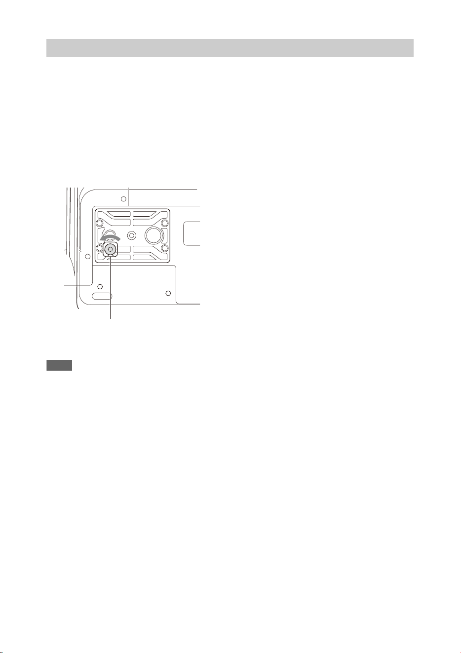
139
If the ND filter will not move, you can move the filter to the CLEAR position manually using the
following procedure.
1. Set the ON/STANDBY switch to STANDBY.
2. Remove the round cap on the bottom side.
3. Insert a screwdriver in the hole and turn it counterclockwise.
The ND filter moves to the CLEAR position by turning counterclockwise. Continue turning until
reaching the CLEAR position.
Use a screwdriver with ø2.4 mm diameter or smaller. The insertion depth of the screwdriver is about
3.2 cm (1 5/16 in.).
4. Set the ND FILTER mode switch (page 8) to the PRESET position, and set the ND FILTER switch
(page 8) to CLEAR.
Notes
• Do not use the procedure above during normal operation. Only use this procedure if the ND filter will not move. The
ND filter may become damaged if this procedure is used during normal operation.
• After the procedure above is used, consult a Sony service center to have the camcorder repaired.
• If an error message still appears after performing the procedure above, shooting is still possible.
ND filter dial
Screwdriver hole (with cap removed)

140
The camcorder informs you of situations where warning, caution, or an operation check is required,
through messages on the viewfinder screen, the recording/tally lamp, and a buzzer.
The warning sound is emitted from the built-in speaker and headphones connected to the headphone
connector.
The camcorder will stop operation when the following kind of display occurs.
Follow the instructions provided if the following display occurs.
Error/Warning Indications
Error indications
Error indication on
LCD/viewfinder
Warning
sound
Recording/
tally lamp
Cause and Solution
E + error code Continuous High-speed
flashing
Indicates an abnormality in the camcorder. Recording stops,
even if “zRec” is displayed in the viewfinder.
Turn off the camcorder, and check for any problem with
connected devices, cables, or media. If the error persists when
the camcorder is turned on again, contact your Sony service
representative.
(If power cannot be turned off by setting the ON/STANDBY
switch to STANDBY, remove the battery pack and/or the DC
IN source.)
An error or warning may not be displayed depending on the
status of the camcorder.
Warning indications
Warning indication on
LCD/viewfinder
Warning
sound
Recording/
tally lamp
Cause and Solution
Battery Near End Intermittent Flashing The remaining capacity of the battery pack is
getting low.
Recharge at the earliest convenience.
Battery End Continuous High-speed
flashing
The battery pack is empty. Recording cannot be
performed.
Stop operation and replace the battery pack.
Temperature High Intermittent Flashing The internal temperature is high.
Turn off the camcorder and allow it to cool down
before operating it again.
Voltage Low Intermittent Flashing The DC IN voltage is low (level 1). Check the
power supply.
Insufficient Voltage Continuous High-speed
flashing
The DC IN voltage is too low (level 2). Recording
cannot be performed.
Connect a different power source.
Media Near Full Intermittent Flashing Free space on the SxS memory card has become
insufficient.
Replace at the earliest convenience.
Media Full Continuous High-speed
flashing
No space is left on the SxS memory card.
Recording, clip copying and clip division cannot be
performed.
Replace immediately.

141
1)“Media(B)” for the card in slot B.
The following caution and operation messages may appear in the center of the screen. Follow the
instructions provided to resolve the issue.
Clips Near Full Intermittent Flashing The number of additional clips that can be recorded
on the SxS memory card is getting low.
Replace at the earliest convenience.
Clips Full Continuous High-speed
flashing
The maximum number of clips that can be recorded
on an SxS memory card has been reached.
Recording or copying more clips is not possible.
Replace immediately.
Last Clip Recording Intermittent Flashing The clip currently recording is the last clip that can
be recorded, as the maximum number of clips has
been reached.
Prepare a new SxS memory card.
Media(A) Near Full
1)
Intermittent Flashing When using the Simul Rec function
Media(A) Full
1)
Continuous High-speed
flashing
When using the Simul Rec function
Media(A) Clips Near Full
1)
Intermittent Flashing When using the Simul Rec function
Media(A) Clips Full
1)
Continuous High-speed
flashing
When using the Simul Rec function
Media(A) Last Clip Rec
1)
Intermittent Flashing When using the Simul Rec function
Warning indication on
LCD/viewfinder
Warning
sound
Recording/
tally lamp
Cause and Solution
Caution and operation messages
Display message Cause and Solution
Battery Error
Please Change Battery
An error was detected in the battery pack.
Replace with a normal battery pack.
Unknown Media(A)
1)
Please Change
A memory card that has been partitioned or a memory card containing
more clips that can be handled by the camcorder was inserted.
The card cannot be used in the camcorder, and must be replaced.
Cannot Use Media(A)
1)
Unsupported File System
A card using a different file system or an unformatted card was inserted.
The card cannot be used in the camcorder, and must be replaced or
formatted using the camcorder.
Media Error
Media(A) Needs to be Restored
1)
An error occurred on the memory card, and the card must be restored.
Restore the memory card.
Media Error
Cannot Record to Media(A)
1)
The memory card may be damaged, and can no longer be used for
recording.
Playback may be possible, so making a copy and replacing the memory
card is recommended.
Media Error
Cannot Use Media(A)
1)
The memory card may be damaged, and can no longer be used for
recording or playback.
The card cannot be used in the camcorder, and must be replaced.
Media(A) Error
1)
Recording Halted
Playback Halted
Recording and playback was stopped because an error occurred while
using the memory card.
If the problem persists, replace the memory card.
Media Reached Rewriting Limit
Change Media(A)
1)
The memory card has reached the end of its life.
Make a backup, and replace the card immediately. If you continue using
the card, the card may not be able to record or play.
For details, refer to the operating instructions for the memory card.

142
1)“Media(B)” for the card in slot B.
Copy All Sub Clips
NG: Reached Clip Number Limit
NG: Same File Already Exists
NG: Not Enough Capacity
Copying of all sub-clips using Copy All Sub Clips failed because of the
displayed reason.
• The maximum number of clips is reached.
• There is a file with the same name.
• There is not enough capacity for copying.
Replace the media.
Invalid setting value was reset:
Media/Clip Naming/Camera Position
Please save All File again
The Clip Naming format setting was reset because an invalid ALL file
was loaded.
Configure the desired format settings, and try to save the ALL file again.
The specified address is invalid. The specified address is invalid.
Check that the setting is correct.
Cannot Use Specified Port Number The specified port number is invalid.
Check that the setting is correct.
Accessing the memory card failed. Accessing the memory card failed.
This error may appear if you cannot access the UTILITY SD/MS slot
media during recording in XAVC-I 3840×2160P 59.94/50P. Try again
after finishing recording.
Failed This error may appear if an address cannot be obtained with DHCP set to
On.
Check the DHCP server settings.
Cannot add auto upload job of Proxy file
because maximum number of upload jobs
was reached.
The maximum number of transfer jobs has been reached.
Clear any unwanted jobs. The auto upload destination setting for proxy
files may also be incorrect. Check that the setting is correct.
<SSID>Not found. Network (access point) with the specified <SSID> could not be found.
Check that the setting is correct.
<SSID>Authentication Failed Connection authentication on the network (access point) with the
specified <SSID> failed.
Check that the password and other settings are correct.
An IP address conflict has occurred. Please
check the network settings.
There is a conflict in the network addresses of the wireless LAN, wired
LAN, or modem.
Change the address manually or change the settings for the network
router.
The IP address of the Wireless LAN Access
Point Mode has been changed due to an IP
address conflict.
The IP address of the wireless LAN access point mode was changed due
to a conflict in the network addresses of the wireless LAN access point
mode, wired LAN, or modem.
Check the IP address setting.
Display message Cause and Solution
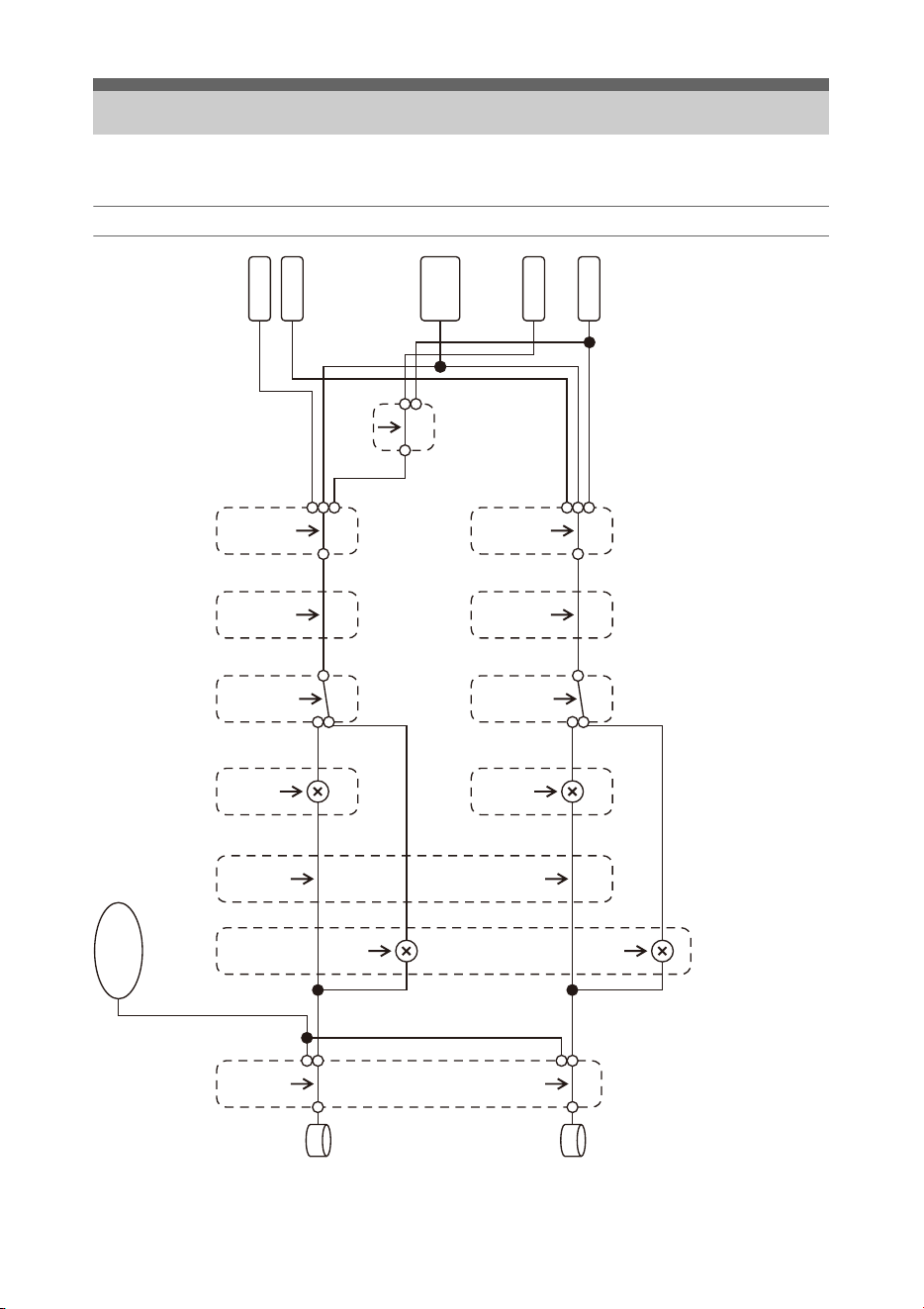
143
See related items in “Setting the audio to record” (page 34) and “Setup Menu List” (page 90).
Audio Input (CH1&2)
Block Diagrams
<CH1 INPUT SELECT>
INT
EXT
MI SHOE
[CH1 Wind Filter]
On
Off
<CH1 LEVEL CONTROL>
AUTO
MAN
<CH1 INPUT LEVEL>
0ˋ10
<CH2 INPUT SELECT>
INT
EXT
MI SHOE
[CH2 Wind Filter]
On
Off
<CH2 LEVEL CONTROL>
AUTO
MAN
<CH2 INPUT LEVEL>
0ˋ10
[Limiter Mode]
Off, ˋ6dB
ˋ9dB, ˋ12dB
ˋ15dB, ˋ17dB
[CH1&2 AGC Mode]
Mono
Stereo
[Color Bar]
[1kHz Tone on Color Bar]
[CH2 EXT Input Select]
INPUT1
INPUT2
L
R
CH1
CH2
SG
INPUT1
Shoe CH1
Shoe CH2
INPUT2
Internal
MIC
One or both are on
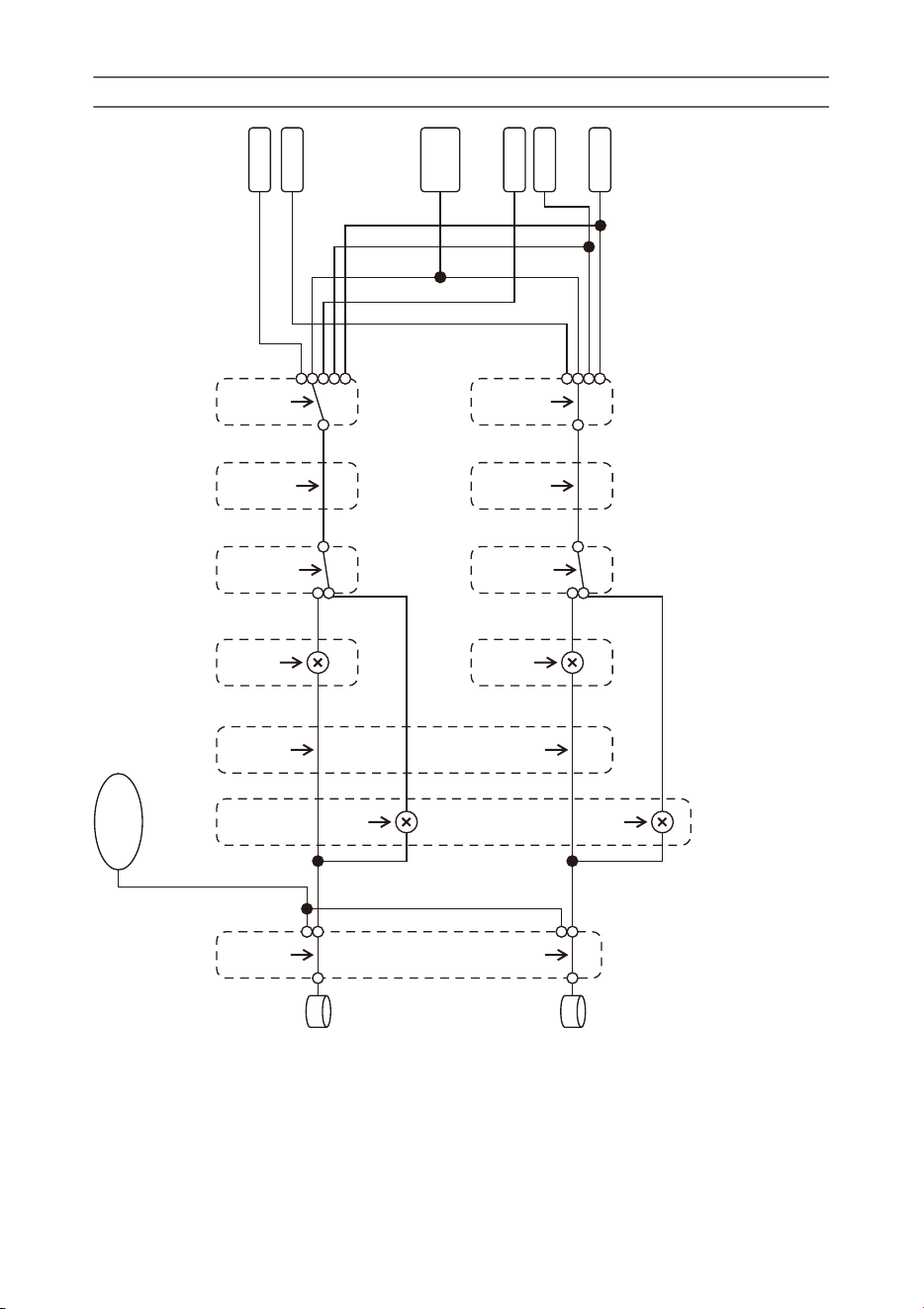
144
Audio Input (CH3&4)
[CH3 Input Select]
Off
INPUT1
Internal MIC
Shoe CH1
[CH3 Wind Filter]
On
Off
<CH3 LEVEL CONTROL>
AUTO
MAN
<CH3 INPUT LEVEL>
0ˋ10
[CH4 Input Select]
Off
INPUT1
INPUT2
Internal MIC
Shoe CH2
[CH4 Wind Filter]
On
Off
<CH4 LEVEL CONTROL>
AUTO
MAN
<CH4 INPUT LEVEL>
0ˋ10
[Limiter Mode]
Off, ˋ6dB
ˋ9dB, ˋ12dB
ˋ15dB, ˋ17dB
[CH3&4 AGC Mode]
Mono
Stereo
[Color Bar]
[1kHz Tone on Color Bar]
L
R
CH3
CH4
SG
OFF
Shoe CH1
Shoe CH2
INPUT1
INPUT2
Internal
MIC
One or both are on
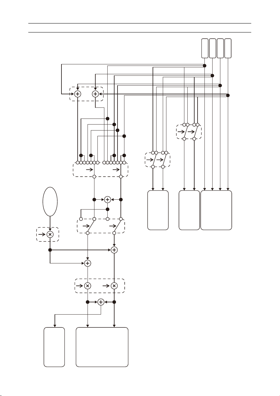
145
Audio Output
[HDMI Output CH]
CH1/CH2,CH3/CH4
CH1
CH2
CH3
CH4
SDI OUT
HDMI OUT
Analog OUT
Headphone
Internal Speaker
Alarm
Beep
[Monitor CH]
CH1,CH2,CH3,CH4,
CH1/CH2,CH3/CH4,
MIX ALL
[Analog Output CH]
CH1/CH2,CH3/CH4
Ch
MIX
[Alarm/Beep Level]
0
ˋ
7
L
R
[Headphone Out]
Mono/Stereo
<VOLUME>
0
ˋ
50

146
Specifications
General
Mass
Approx. 2.6 kg (5 lb 11.7 oz) (body only)
Approx. 3.0 kg (6 lb 9.8 oz) (With lens hood (1),
eyecup (1), BP-U30 battery pack (1), SxS
memory card (1))
Dimensions (width / height / depth)
178.4 mm × 202.0 mm × 426.3 mm
7
1
/
8
in. × 8 in. × 16
7
/
8
in.
Maximum dimensions. Depth is the length
from the front of the lens hood to the large
eyecup.
Power requirements
12 V DC (11 V to 16.5 V)
Power consumption
Approx. 24 W
while recording with LCD screen off,
viewfinder on, no external device connected
Approx. 36 W
while recording with LCD screen on,
viewfinder on, using HD SDI, HDMI and
external device
Approx. 36 W
when copying to USB media
Operating temperature
0 °C to 40 °C (32 °F to 104 °F)
Storage temperature
–20 °C to +60 °C (–4 °F to +140 °F)
Continuous operating time
When using BP-U90 battery pack:
Approx. 3 hours 15 minutes
When using BP-U60 battery pack:
Approx. 2 hours 10 minutes
When using BP-U30 battery pack:
Approx. 1 hour 5 minutes
(While recording with LCD screen off,
viewfinder on, no external device connected)
Recording format (video)
XAVC Intra
XAVC-I QFHD mode: CBG, 600 Mbps (max),
MPEG-4 AVC/H.264
XAVC-I HD mode: CBG, 222 Mbps (max),
MPEG-4 AVC/H.264
XAVC Long
XAVC-L QFHD mode: VBR, 150 Mbps (max),
MPEG-4 H.264/AVC
XAVC-L HD 50 mode: VBR, 50 Mbps (max),
MPEG-4 H.264/AVC
XAVC-L HD 35 mode: VBR, 35 Mbps (max),
MPEG-4 H.264/AVC
XAVC-L HD 25 mode: VBR, 25 Mbps (max),
MPEG-4 H.264/AVC
MPEG-2 Long GOP
MPEG HD422 mode: CBR, 50 Mbps (max),
MPEG-2 422P@HL
MPEG HD420 HQ mode: VBR, 35 Mbps
(max), MPEG-2 MP@HL
DVCAM
CBR, 25 Mbps
Proxy
AVC/H.264 Main Profile 4:2:0 Long GOP, VBR
1920×1080/9 Mbps, 1280×720/9 Mbps,
1280×720/6 Mbps, 640×360/3 Mbps,
480×270/1 Mbps, 480×270/500 kbps
Recording format (audio)
XAVC Intra
XAVC-I mode: LPCM 24-bit, 48 kHz,
4 channels
XAVC Long
XAVC-L mode: LPCM 24-bit, 48 kHz,
4 channels
MPEG-2 Long GOP
MPEG HD422 mode: LPCM 24-bit, 48 kHz,
4 channels
MPEG HD420 HQ mode: LPCM 16-bit,
48 kHz, 4 channels
DVCAM
LPCM 16-bit, 48 kHz, 4 channels
Proxy
AAC-LC, 128 kbps, 2 channels

147
Recording frame rate
XAVC Intra
XAVC-I QFHD mode: 3840×2160/59.94P, 50P,
29.97P, 23.98P, 25P
XAVC-I HD mode: 1920×1080/59.94P, 59.94i,
50P, 50i, 29.97P, 23.98P, 25P
1280×720/59.94P, 50P
XAVC Long
XAVC-L QFHD 150 mode: 3840×2160/59.94P,
50P, 29.97P, 23.98P, 25P
XAVC-L HD 50 mode: 1920×1080/59.94P, 50P,
59.94i, 50i, 29.97P, 23.98P, 25P
1280×720/59.94P, 50P
XAVC-L HD 35 mode: 1920×1080/59.94P, 50P,
59.94i, 50i, 29.97P, 23.98P, 25P
XAVC-L HD 25 mode: 1920×1080/59.94i, 50i
MPEG-2 Long GOP
MPEG HD422 mode: 1920×1080/59.94i, 50i,
29.97P, 23.98P, 25P
1280×720/59.94P, 50P, 29.97P, 23.98P, 25P
MPEG HD420 HQ mode: 1920×1080/59.94i,
50i, 29.97P, 23.98P, 25P
1440×1080/59.94i, 50i
1280×720/59.94P, 50P
DVCAM
720×480/59.94i, 29.97PsF
720×576/50i, 25PsF
Recording/playback time
XAVC Intra
XAVC-I QFHD mode
When using SBP-128B (128 GB): Approx.
22 minutes
XAVC-I HD mode
When using SBP-128B (128 GB): Approx.
57 minutes
XAVC Long
XAVC-L QFHD 150 mode
When using SBP-128B (128 GB): Approx.
86 minutes
XAVC-L HD 50 mode
When using SBP-128B (128 GB): Approx.
230 minutes
XAVC-L HD 35 mode
When using SBP-128B (128 GB): Approx.
310 minutes
XAVC-L 25 mode
When using SBP-128B (128 GB): Approx.
420 minutes
MPEG-2 Long GOP
MPEG HD422 mode
When using SBP-128B (128 GB): Approx.
215 minutes
MPEG HD420 HQ mode
When using SBP-128B (128 GB): Approx.
330 minutes
DVCAM
When using SBP-128B (128 GB): Approx.
405 minutes
Note
• The recording/playback time may vary due to
usage conditions and memory characteristics.
Lens
Lens mount
Fixed type
Zoom ratio
17×
Focal length
5.6 mm to 95.2 mm
(35 mm equivalent of 30.3 mm to 515 mm)
Focus area
AF/MF/Full MF selectable
800 mm to ∞ (macro OFF)
50 mm to ∞ (macro ON, wide angle)
800 mm to ∞ (macro ON, telephoto)

148
Iris
Auto/manual selectable
F1.9 to F16 and C (Close)
Image stabilization
ON/OFF selectable, shift lens
Filter diameter
M77 mm, 0.75 mm pitch
Macro
ON/OFF selectable
Camera
Imaging device
1/2-inch type ExmorR 3-CMOS image sensor
Effective picture elements
3840 (H) × 2160 (V)
Optical system
F1.6 prism system
Built-in filters
ND filters
CLEAR: Clear
1: 1/4ND
2: 1/16ND
3: 1/64ND
Linear variable ND (Approx. 1/4 ND to 1/128
ND)
Sensitivity (2000 lx, 89.9% reflectance)
F12 (typical, 1920×1080/59.94P mode)
F13 (typical, 1920×1080/50P mode)
F12 (typical, 3840×2160/59.94P, high sensitivity
mode)
F13 (typical, 3840×2160/50P, high sensitivity
mode)
Minimum illumination
0.0013 lx (typical, 1920×1080/59.94i) (F1.9,
+42 dB high sensitivity mode, 64-frame
accumulation)
S/N ratio
63 dB (Y) (typical)
Horizontal resolution
2000 TV lines or more (3840×2160P mode)
1000 TV lines or more (1920×1080P mode)
Shutter speed
64F to 1/8000 sec.
Slow & Quick Motion
XAVC Intra, XAVC Long
2160P: 1 to 60 fps
1080P: 1 to 60 fps
720P: 1 to 60 fps
MPEG HD422
1080P: 1 to 30 fps
720P: 1 to 60 fps
MPEG HD420 HQ
1080P: 1 to 30 fps
720P: 1 to 60 fps
White balance
Preset mode (3200K)
Memory A mode, Memory B, ATW mode
Gain
–3, 0, 3, 6, 9, 12, 15, 18 dB, 42 dB (Turbo Gain
on), AGC
Gamma curve
Selectable
Wireless LAN
Supported standards
IEEE 802.11a/b/g/n/ac
Frequency bands
2.4 GHz
5.2/5.3/5.6 GHz (PXW-Z280V only)
Security
WEP/WPA-PSK/WPA2-PSK
NFC Forum Type 3 Tag compliant
Inputs/outputs
Audio input
XLR type 3-pin (2), female, LINE/MIC/
MIC+48V switchable
LINE: +4dBu/0dBu/–3dBu (/EBUL) / 10 kΩ
MIC: –80dBu to –30dBu / 3 kΩ
(Reference input level 0 dBu=0.775 Vrms)
Audio output
Multi/Micro USB
Video output
BNC type (1), switchable with GENLOCK IN
connector, HD-Y/HD-SYNC/composite signal
1.0 Vp-p, 75 Ω
SDI output
BNC type (1), 12G/3G/HD/SD selectable

149
Battery pack (1)
AC adapter/charger (1)
USB cable (1)
Lens hood (1)
Large eyecup (1)
Shoulder strap (1)
CD-ROM “Operating instructions” (1)
Before Using This Unit (1)
Warranty booklet (1)
Software Downloads
When the unit is used with a PC connection,
download device drivers, plug-ins, and
application software, where applicable, from the
Sony Professional products web site.
Sony Professional products web site homepage:
U.S.A. http://pro.sony.com
Canada http://www.sonybiz.ca
Latin America http://sonypro-latin.com
Europe, Middle East and Africa
http://www.pro.sony.eu
Japan http://www.sonybsc.com
Asia Pacific http://pro.sony-asia.com
Korea http://bp.sony.co.kr
China http://pro.sony.com.cn
Although the data regarding recorded materials
are stored over multiple files and folders, you can
easily handle the clips without considering its
data and directory structure, by using the
dedicated application software.
Note
• If you perform operations on clips, such as copying the
clips on the SxS memory card using Explorer
(Windows) or Finder (Macintosh), the subsidiary data
contained by the clips may not be maintained.
Design and specifications are subject to change
without notice.
Timecode input
BNC type (1), switchable with TC OUT
connector
0.5 V to 18 Vp-p, 3.3 kΩ
Timecode output
BNC type (1), switchable with TC IN connector
1.0 Vp-p, 75 Ω
GENLOCK input
BNC type (1), switchable with VIDEO OUT
connector
1.0 Vp-p, 75 Ω
USB connector
Multi/Micro USB (1)
Host: USB 3.0/2.0 type A (1), USB 2.0 type A
(1)
Headphone output
Stereo mini jack (1)
–16 dBu, 16 Ω
Speaker output
Monaural
Output: 500 mW
DC input
DC jack
HDMI output
HDMI connector (type A)
REMOTE connector
Stereo sub-mini jack (ø2.5 mm)
Wired LAN connector
RJ-45 (1), 1000BASE-T, 100BASE-T,
10BASE-T
Display
Viewfinder
Screen size: 1.3 cm (0.5-inch type)
Effective pixels: Approx. 2.36M dots
LCD screen
Screen size: 8.8 cm (3.5-inch type)
Effective pixels: Approx. 1.56M dots
Internal microphone
Internal microphone
Omnidirectional stereo electret condenser
microphone
Media slots
Type
ExpressCard/34 (2)
SD/MS (1)
Supplied accessories

150
Trademarks
• XDCAM is a trademark of Sony Corporation.
• XAVC and are registered trademarks of
Sony Corporation.
• XQD and are trademarks of Sony
Corporation.
• Microsoft, Windows, Windows Vista, and
Windows Media are trademarks or registered
trademarks of U.S. Microsoft Corporation in the
U.S. and other countries.
• Mac and Mac OS are registered trademarks of
Apple Inc. in the U.S. and other countries.
• HDMI, HDMI logo, and High-Definition
Multimedia Interface are registered trademarks
of HDMI Licensing LLC in the United States
and other countries.
• Adobe, the Adobe logo, and Adobe Acrobat are
either registered trademarks or trademarks of
Adobe Systems Incorporated in the United
States and/or other countries.
• “Memory Stick”, “Memory Stick Duo,”
“Memory Stick PRO Duo,” “Catalyst Browse,”
“Content Browser Mobile,” and the “Content
Browser Mobile” logo are trademarks or
registered trademarks of Sony Corporation.
• SxS, SxS PRO and SxS-1 are trademarks of
Sony Corporation.
• The ExpressCard label and logo are the
property of the Personal Computer Memory
Card International Association (PCMCIA) and
are licensed to Sony Corporation. All other
trademarks and trade names are the property of
their respective owners.
• SDXC logo is a trademark of SD-3C, LLC.
• iOS is a registered trademark or trademark of
Cisco Systems, Inc. and/or its affiliates in the
United States and certain other countries.
• Android, Google Play are trademarks of Google
Inc.
• Wi-Fi, the Wi-Fi logo, and Wi-Fi
PROTECTED SETUP are trademarks or
registered trademarks of Wi-Fi Alliance.
• The N Mark is a trademark or registered
trademark of NFC Forum, Inc. in the United
States and in other countries.
All other company names and product names are
registered trademarks or trademarks of their
respective owners. Trademarked items are not
indicated by ™ or ® symbols in this document.
Licenses
THIS PRODUCT IS LICENSED UNDER THE
AVC PATENT PORTFOLIO LICENSE FOR
THE PERSONAL AND NON-COMMERCIAL
USE OF A CONSUMER TO
(i) ENCODE VIDEO IN COMPLIANCE WITH
THE AVC STANDARD (“AVC VIDEO”) AND/
OR
(ii) DECODE AVC VIDEO THAT WAS
ENCODED BY A CONSUMER ENGAGED IN
A PERSONAL AND NON-COMMERCIAL
ACTIVITY AND/OR WAS OBTAINED FROM
Notes
• Always make a test recording, and verify that
it was recorded successfully.
SONY WILL NOT BE LIABLE FOR
DAMAGES OF ANY KIND INCLUDING,
BUT NOT LIMITED TO, COMPENSATION
OR REIMBURSEMENT ON ACCOUNT OF
FAILURE OF THIS UNIT OR ITS
RECORDING MEDIA, EXTERNAL
STORAGE SYSTEMS OR ANY OTHER
MEDIA OR STORAGE SYSTEMS TO
RECORD CONTENT OF ANY TYPE.
• Always verify that the unit is operating
properly before use. SONY WILL NOT BE
LIABLE FOR DAMAGES OF ANY KIND
INCLUDING, BUT NOT LIMITED TO,
COMPENSATION OR REIMBURSEMENT
ON ACCOUNT OF THE LOSS OF
PRESENT OR PROSPECTIVE PROFITS
DUE TO FAILURE OF THIS UNIT, EITHER
DURING THE WARRANTY PERIOD OR
AFTER EXPIRATION OF THE
WARRANTY, OR FOR ANY OTHER
REASON WHATSOEVER.
• SONY WILL NOT BE LIABLE FOR
CLAIMS OF ANY KIND MADE BY USERS
OF THIS UNIT OR MADE BY THIRD
PARTIES.
• SONY WILL NOT BE LIABLE FOR THE
LOSS, REPAIR, OR REPRODUCTION OF
ANY DATA RECORDED ON THE
INTERNAL STORAGE SYSTEM,
RECORDING MEDIA, EXTERNAL
STORAGE SYSTEMS OR ANY OTHER
MEDIA OR STORAGE SYSTEMS.
• SONY WILL NOT BE LIABLE FOR THE
TERMINATION OR DISCONTINUATION
OF ANY SERVICES RELATED TO THIS
UNIT THAT MAY RESULT DUE TO
CIRCUMSTANCES OF ANY KIND.

151
A VIDEO PROVIDER LICENSED TO
PROVIDE AVC VIDEO.
NO LICENSE IS GRANTED OR SHALL BE
IMPLIED FOR ANY OTHER USE.
ADDITIONAL INFORMATION MAY BE
OBTAINED FROM MPEG LA, L.L.C. SEE
HTTP://WWW.MPEGLA.COM
On the basis of license contracts between Sony
and the software copyright holders, this product
uses open software. To meet the requirements of
the software copyright holders, Sony is obligated
to inform you of the content of these licenses.
Obtaining software under the GPL/LGPL license
This product uses software to which the GPL/
LGPL applies. This informs you that you have a
right to have access to, modify, and redistribute
source code for these software programs under
the conditions of the GPL/LGPL.
The source code is provided on the internet. Use
the following URL and follow the download
instructions.
http://www.sony.net/Products/Linux/common/
search.html
We would prefer that you do not contact us about
the contents of the source code.
Licenses (in English) are recorded in the internal
memory of your product.
Establish a Mass Storage connection between the
product and a computer to read licenses in the
“PMHOME” - “LICENSE” folder.

152
A
AC adapter 20
All File 113
All Reset 123
Aperture 99
Assignable Button 40, 121
Assignable buttons 40
ATW 33
Audio 30
Audio Input 101
AUDIO INPUT1 connector 34
AUDIO INPUT2 connector 34
Audio menu 101
Audio monitoring 30
Audio Output 102
Auto Black Balance 93
Auto Exposure 92
Auto tracing white balance 33
Auto white balance 33
B
Battery Alarm 122
Battery pack 19
Black 96
Black Gamma 97
C
Camera menu 91
Caution and operation messages 141
Charger 19
Clip 28, 73, 74, 81, 111
Clip Continuous Rec 108
Clip name 28
Clock 21
Clock Set 122
Color Bars 93
Condensation 126
Customize View 110
D
Date and time 21
Delete Clip 109
Detail (HD mode) 98
Detail (SD mode) 99
Display Clip Properties 75, 109
Display On/Off 105
Down Converter 102
E
Error indications 140
External monitor 79
F
Face Detection AF 12, 37
File menu 112
Filter Clips 110
Flicker Reduce 93
Focus Magnifier 29
Focus ring 29
FOCUS switch 29
Format Media 110
Formatting 23, 25, 26
Full MF mode 29
G
Gain 31, 91
GAIN switch 31
Gamma 96
GENLOCK IN/VIDEO OUT connector 79,
135
GPS 122
H
Handle Zoom 93
Handle zoom 28
Handle zoom lever 28
Handle zoom switch 28
HDMI OUT connector 79, 133
HDMI TC Out 107
Headphone jack 30
Hours Meter 122
I
Image stabilization 36
INPUT1 switch 34
INPUT2 switch 34
Iris ring 31
IRIS switch 31
K
Knee 97
Index

153
L
Language 122
LCD screen 12
LCD Setting 103
LCD/VF menu 103
Lens 126
Lens hood with lens cover 21
Lock/Unlock Clip 109
M
Maintenance 100
Marker 104
Matrix 100
MEAD-SD02 26
Media adapter 25
Media Full 24
Media menu 110
Media Near Full 24
Memory A mode 33
Memory B mode 33
MENU button 86
Multi Matrix 100
N
ND Filter 91
ND filter 32
Network menu 113
Nonlinear editing 82
O
Output Display 102
Output Format 102
Output On/Off 102
Output signal 132
P
Paint menu 94
Peaking 103
Planning Metadata 112
Planning metadata 49
Pre-installed rechargeable battery 126
Preset mode 32
Proxy recording mode 109
PUSH (lens hood release) button 21
R
Rec Format 118
Record button 27
Recording menu 107
S
S&Q Motion 107
Scene File 113
SD cards 26
SDI OUT connector 79, 132
SEL/SET dial 86
Set Clip Flag 109
Set Index Picture 109
Set Shot Mark 109
Setup menu 84, 86, 90
Shoulder strap 10
Shutter 92
Simul Rec 108
Skin Detail 99
SLOT SELECT button 23
SteadyShot 36
SxS memory cards 23
System menu 118
T
TC/UB menu 107
Telephoto 28
Thumbnail menu 109
Thumbnail screen 72
Thumbnail View 110
Time data 36
Time Zone 21
Timecode 36, 107
U
Update Media 110
USB cable 81
USB wireless LAN module 54
User bits 36
User menu 90
Users Bit 107
Using your camcorder abroad 124
UTC 21
V
Version 123
VF Setting 103
Video format 132
Video Light Set 94
Video menu 102

154
Viewfinder 12
diopter adjustment knob 22
VOLUME buttons 30
W
Wall outlet (wall socket) 20
Warning indications 140
WB SET button 32
Web remote control 68
White 95
White balance 32
White Clip 98
White Switch 95
WHT BAL switch 33
Wide angle 28
X
XQD memory cards 25
Z
Zebra 105
Zoom 28
Zoom lever 28
Zoom ring 29