Loading ...
Loading ...
Loading ...
Before You Start
Set-Up
1
1-29
Caution
Follow the specified steps on how to
establish the required connections.
1. Connect the thermography camera to the breakout
box. For this, the 14-pin connecting cable of the
breakout box must be used. It is connected to the
right-hand side 14-pin LEMO socket on the backside
of the thermal imager.
2. Connect the breakout box to the COM interface of
the host computer with a commercially available
cable.
3. Connect the supplied ac adapter to the breakout box.
4. Push the Power button
on the backside of the
camera to turn on the thermography system.
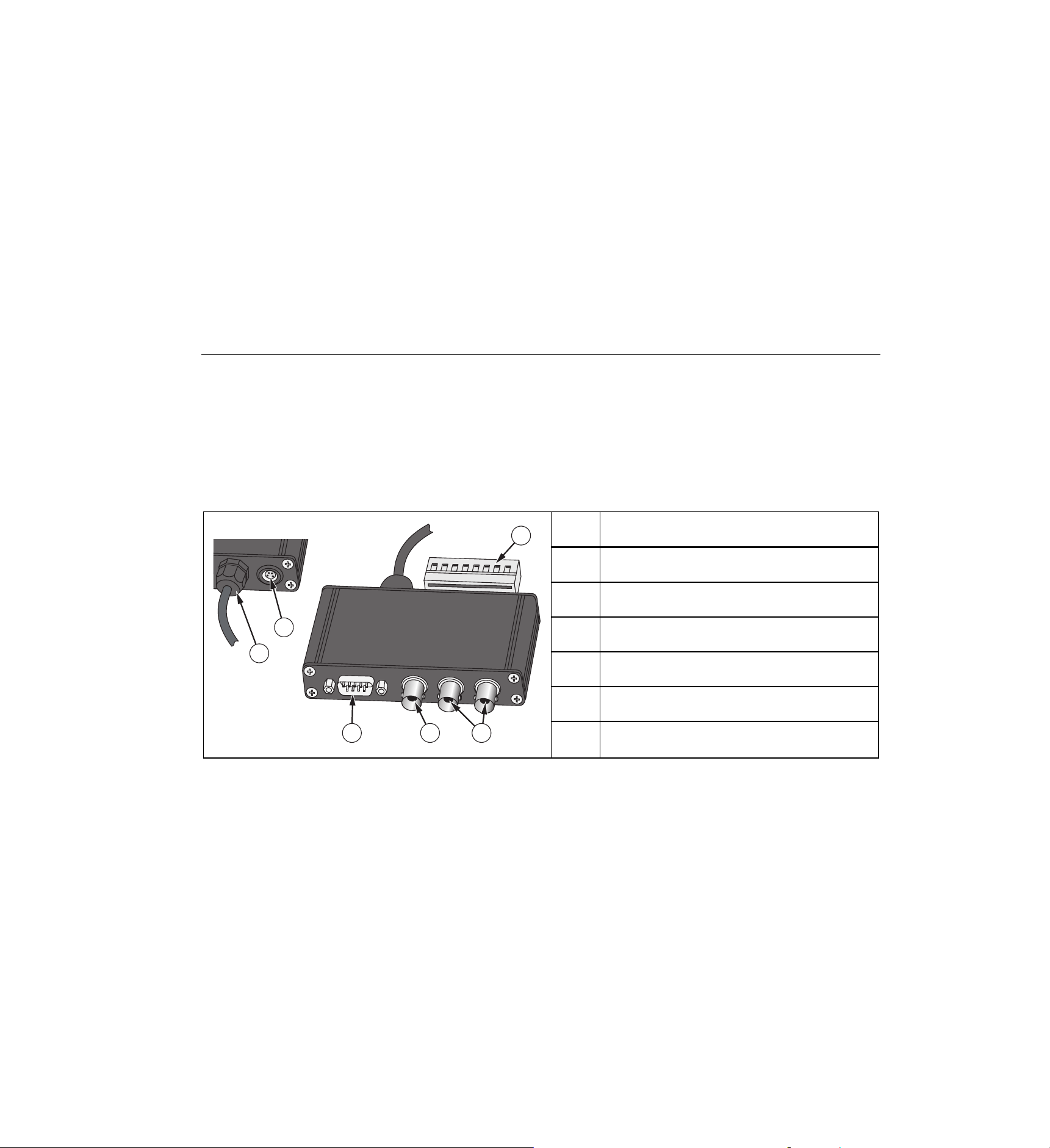
Table 1-8. Breakout Box
2
1
6 5 4
3
hvh061.eps
Item Description
Connecting cable for thermal imager
14-pin LEMO socket for ac adapter
Terminal strip
Trigger T1, T2 (configurable)
BNC video port (PAL/NTSC-FBAS)
Serial interface (RS232)
1.888.610.7664 sales@GlobalTestSupply.com
Fluke-Direct
.com
Loading ...
Loading ...
Loading ...