Updated 03/07/24
1
www.akiascreens.com
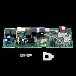
Circuit Board Replacement
Ins
tr
u
c
tions
For technical support or further assistance please contact us at
ATTENTION: Please make sure the version number and the Voltage of the circuit board matches the
version number and the Voltage of the screen. Akia Screens does not recommend making unnecessary
adjustments to the screen, as improper adjustments will damage the unit and void your warranty.
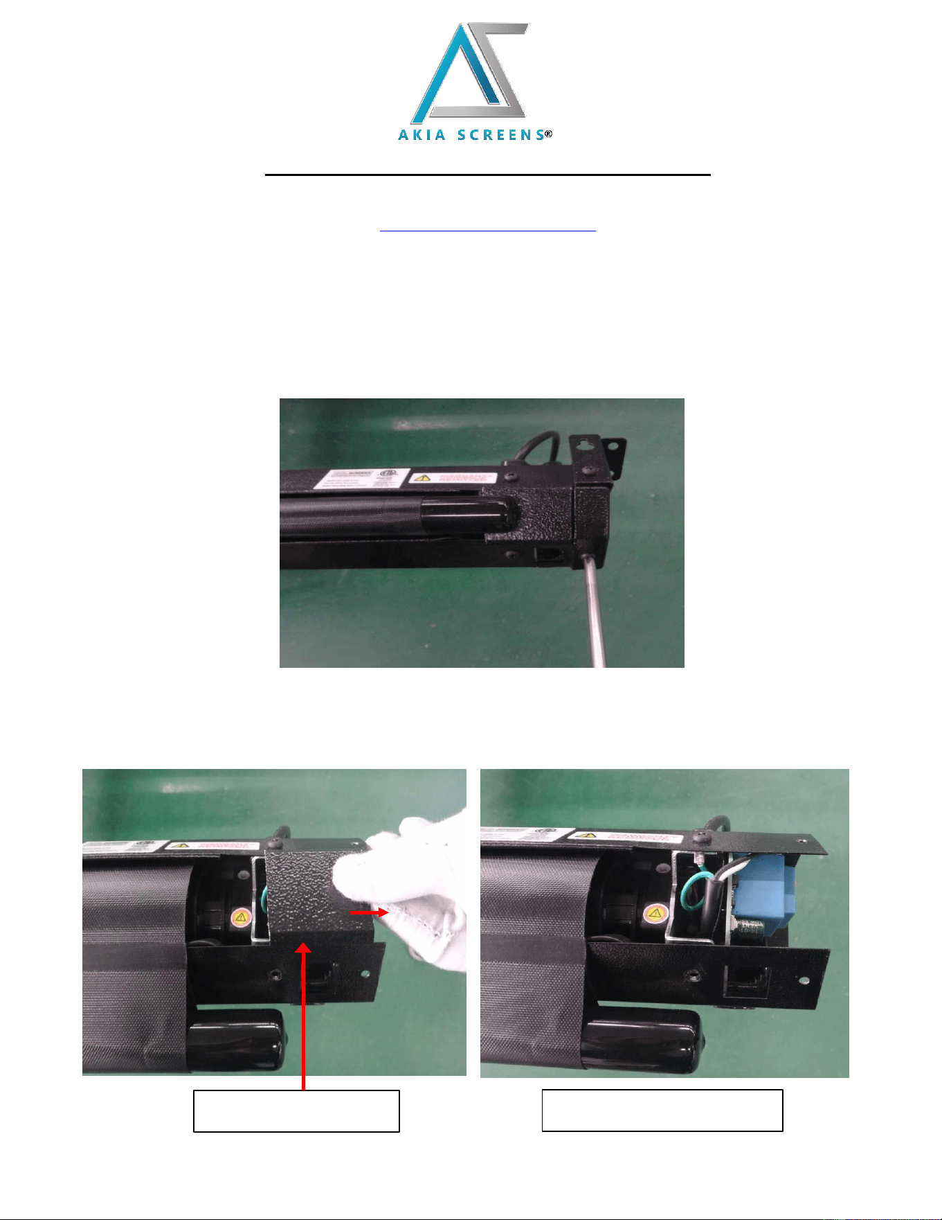
1. Remove the screws on the left end cap (facing the screen) with a Phillips screwdriver, then remove
the end cap.
2. After removing the end cap, carefully remove the decorative sheet by pulling it outward towards
the open end. Note: Keep in mind how the ground wire (green) is connected, as this will be
needed at a later step.
Decorative sheet Decorative sheet removed
Updated 03/07/24
2
www.akiascreens.com
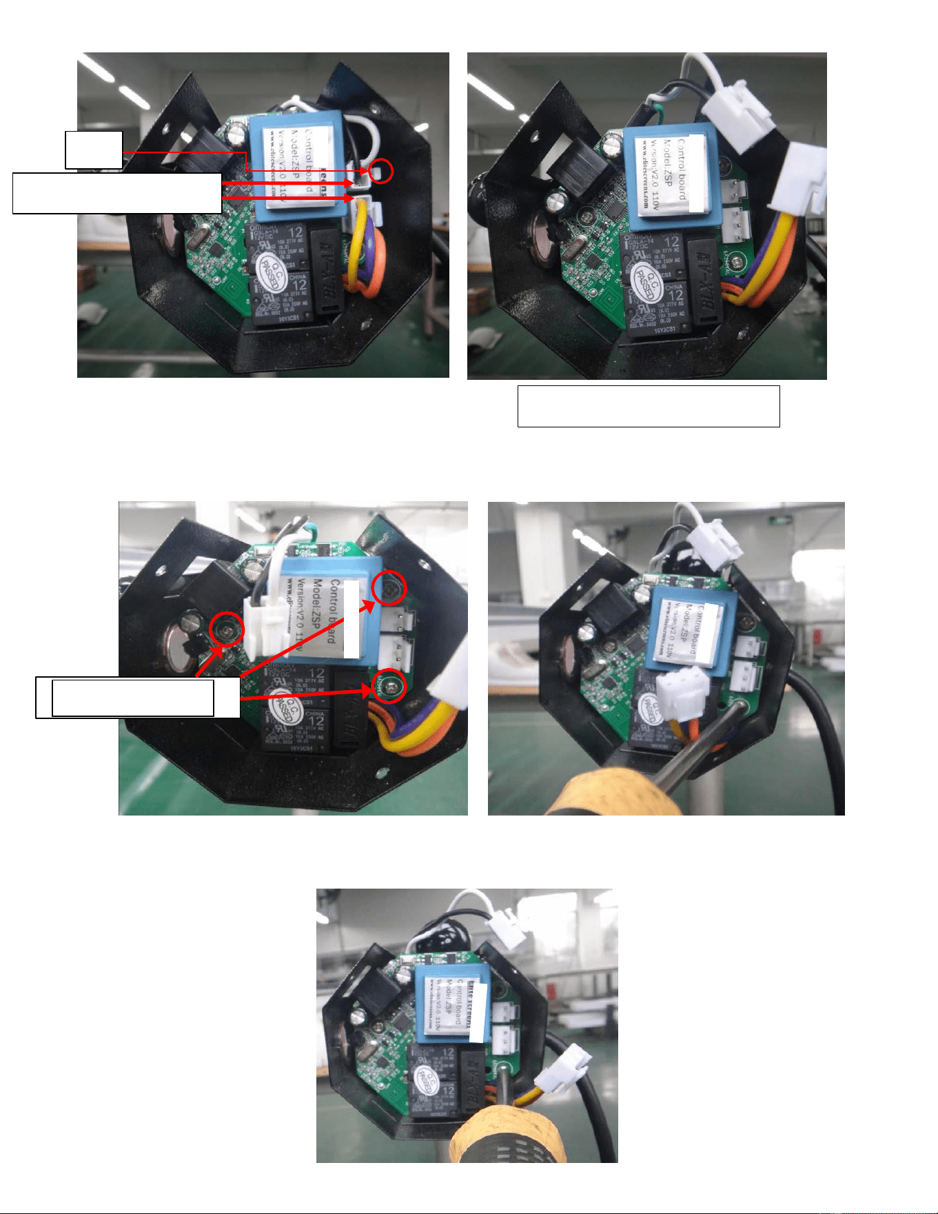
3. Press in the clip on the white terminal, then pull out to remove the two white terminals.
clip
Two white terminals
Two white terminals removed
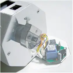
4. Remove the three screws that secure the circuit board with a Phillips head screwdriver. Set the
screws aside to later secure the new circuit board.
5. Utilize the saved screws to secure the new circuit board in same location of the previous. Make
sure the ground wire (green) is connected.
Three Screws
Updated 03/07/24
3
www.akiascreens.com
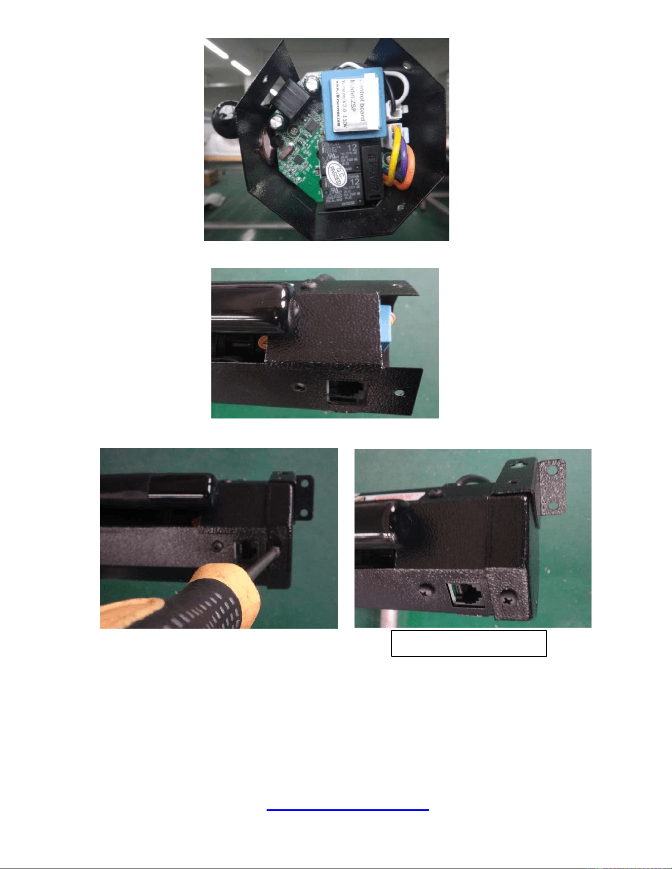
6. Insert the two sets of white terminals into the new circuit board.
7. Replace the decorative sheet removed in step 2.
8. Replace and secure the end cap with screws removed in step 1.
Finished assembly.
NOTE: After replacing the circuit board, the original screen RF remote control needs to be re-synchronized:
1. While the screen is not plugged in, press and hold the "up" button on the RF remote control and quickly
plug in the screen. 2. Wait for 5 seconds to release the “up” button. (The indicator on the remote control
will flash.) At this point the RF remote control can control the screen.
For a local Akia Screens contact or Technical Support, please
visit
www.akiascreens.com