QUESTIONS OR COMMENTS?
COUNTRY CALL
OR VISIT US
ONLINE AT
UK 0333 000 0333
www.samsung.com/uk/
support
IRELAND (EIRE) 0818 717100
www.samsung.com/ie/
support
GERMANY 06196 77 555 77
www.samsung.com/de/
support
FRANCE 01 48 63 00 00
www.samsung.com/fr/
support
ITALIA
800-SAMSUNG
(800.7267864)
www.samsung.com/it/
support
SPAIN 91 175 00 15
www.samsung.com/es/
support
PORTUGAL 808 207 267
www.samsung.com/pt/
support
LUXEMBURG 261 03 710
www.samsung.com/
be_fr/support
NETHERLANDS 088 90 90 100
www.samsung.com/nl/
support
BELGIUM 02-201-24-18
www.samsung.com/be/
support (Dutch)
www.samsung.com/
be_fr/support (French)
NORWAY 21629099
www.samsung.com/no/
support
DENMARK 707 019 70
www.samsung.com/dk/
support
FINLAND 030-6227 515
www.samsung.com//
support
SWEDEN 0771 726 786
www.samsung.com/se/
support
POLAND
801-172-678* lub +48
22 607-93-33*
* (opłata według taryfy
operatora)
http://www.samsung.
com/pl/support/
HUNGARY
0680SAMSUNG (0680-
726-7864)
www.samsung.com/hu/
support
AUSTRIA
0800 72 67 864
(0800-SAMSUNG)
www.samsung.com/at/
support
SWITZERLAND 0800 726 786
www.samsung.com/ch/
support (German)
www.samsung.com/
ch_fr/support (French)
COUNTRY CALL
OR VISIT US
ONLINE AT
CZECH
800 - SAMSUNG
(800-726786)
www.samsung.com/cz/
support
SLOVAKIA
0800 - SAMSUNG
(0800-726 786)
www.samsung.com/sk/
support
CROATIA 072 726 786
www.samsung.com/hr/
support
BOSNIA 055 233 999
www.samsung.com/ba/
support
MONTENEGRO 020 405 888
www.samsung.com/
support
SLOVENIA
080 697 267
(brezplačna številka)
www.samsung.com/si/
support
SERBIA 011 321 6899
www.samsung.com/rs/
support
ALBANIA 045 620 202
www.samsung.com/al/
support
BULGARIA
0800 111 31 - Безплатен за
всички оператори
*3000 - Цена на един
градски разговор или
според тарифата на
мобилният оператор
09:00 до 18:00 -
Понеделник до Петък
www.samsung.com/bg/
support
ROMANIA
0800872678 - Apel
gratuit
*8000 - Apel tarifat
în reţea
www.samsung.com/ro/
support
CYPRUS
8009 4000 only from
landline, toll free
www.samsung.com/gr/
support
GREECE
80111-SAMSUNG
(80111 726 7864) only
from land line
(+30) 210 6897691
from mobile and land
line
LITHUANIA 8-800-77777
www.samsung.com/lt/
support
LATVIA 8000-7267
www.samsung.com/lv/
support
ESTONIA 800-7267
www.samsung.com/ee/
support

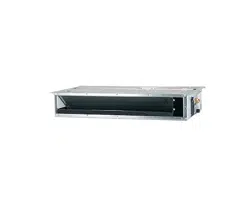
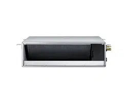
Air conditioner
User manual
AM093MNQDEH
• Thank you for purchasing this Samsung air conditioner.
• Before operating this unit, please read this user manual carefully and retain it for future reference.
2 English
Contents
Safety Information 4
Safety Information 4
At a Glance 12
Indoor Unit Overview 12
Display
Remote Control Overview 13
Replacing batteries
Storing the remote control
Basic Operation 15
Operation Modes 15
Auto
Cool
Dry
Fan
Heat
Turning the air conditioner on
Selecting the operation mode
Adjusting the temperature
Selecting the fan speed
Selecting air flow direction
Advanced Operation 19
Setting the On or Off timer 19
Setting the On timer
Setting the Off timer
Using the good’sleep Function 21
Using the Turbo Function 23
Controlling Indoor Units 24
Cleaning and Maintenance 25
Cleaning the Air Conditioner 25
Cleaning the exterior
Disassembling the air filter
3English
Appendix 29
Troubleshooting 29
Operation Ranges 31
Model specification (Dimension and weight)
Installation part 33
Installation Procedure 33
Correct Disposal of This Product
(Waste Electrical & Electronic Equipment)
(Applicable in countries with separate collection systems)
This marking on the product, accessories or literature indicates that the product and its electronic accessories (e.g.
charger, headset, USB cable) should not be disposed of with other household waste at the end of their working
life. To prevent possible harm to the environment or human health from uncontrolled waste disposal, please
separate these items from other types of waste and recycle them responsibly to promote the sustainable reuse of
material resources.
Household users should contact either the retailer where they purchased this product, or their local government
office, for details of where and how they can take these items for environmentally safe recycling.
Business users should contact their supplier and check the terms and conditions of the purchase contract. This
product and its electronic accessories should not be mixed with other commercial wastes for disposal.
For information on Samsung’s environmental commitments and product-specific regulatory obligations, e.g.
REACH, visit: www.samsung.com/uk/aboutsamsung/sustainability/environment/our-commitment/data/
4 English
Safety Information
Safety Information
Before using your new air conditioner, please read this manual
thoroughly to ensure that you know how to safely and efficiently
operate the extensive features and functions of your new appliance.
Because the following operating instructions cover various models,
the characteristics of your air conditioner may differ slightly from
those described in this manual. If you have any questions, call your
nearest contact centre or find help and information online at www.
samsung.com.
WARNING
Hazards or unsafe practices that may result in severe personal
injury or death.
CAUTION
Hazards or unsafe practices that may result in minor personal
injury or property damage.
Follow directions. Do NOT attempt.
Make sure the machine is grounded to prevent electric shock.
Cut off the power supply. Do NOT disassemble.
FOR INSTALLATION
WARNING
Use the power line with the power specifications of the
product or higher and use the power line for this appliance
only. In addition, do not use an extension line.
• Extending the power line may result in electric shock or fire.
• Do not use an electric transformer. This may result in electric
shock or fire.
Safety Information
5English
Safety InformationSafety Information
• If the voltage/frequency/rated current condition is different,
it may cause fire.
The installation of this appliance must be performed by a
qualified technician or service company.
• Failing to do so may result in electric shock, fire, explosion,
problems with the product, or injury and may also void
warranty on the installed product.
Install an Isolation Switch next to the Air Conditioner (but
not on the panels of the Air Conditioner) and circuit breaker
dedicated to the air conditioner.
• Failing to do so may result in electric shock or fire.
Fix the outdoor unit firmly so that the electric part of the
outdoor unit is not exposed.
• Failing to do so may result in electric shock, fire, explosion,
or problems with the product.
Do not install this appliance near a heater, or inflammable material.
Do not install this appliance in a humid, oily or dusty location, in a
location exposed to direct sunlight and water (rain drops). Do not
install this appliance in a location where gas may leak.
• This may result in electric shock or fire.
Never install the outdoor unit in a location such as on a high
external wall where it could fall.
• If the outdoor unit falls, it may result in injury, death or
property damage.
This appliance must be properly grounded. Do not ground the
appliance to a gas pipe, plastic water pipe, or telephone line.
• Failure to do so may result in electric shock, fire, an
explosion, or other problems with the product.
• Make sure to use a socket-outlet with ground.
Safety Information
6 English
Safety Information
CAUTION
Please cover the air conditioner with PE BAG after installation,
and remove it when you start to run air conditioner.
Install your appliance on a level and hard floor that can
support its weight.
• Failing to do so may result in abnormal vibrations, noise, or
problems with the product.
Install the drain hose properly so that water drains correctly.
• Failing to do so may result in water overflowing and
property damage. Avoid adding drain to waste pipes as
odours may arise in the future.
When installing the outdoor unit, make sure to connect the
drain hose so that draining is performed correctly.
• The water generated during the heating operation in the
outdoor unit may overflow and result in property damage.
In particular, in winter, if a block of ice falls, it may result in
injury, death or property damage.
FOR POWER SUPPLY
WARNING
When the circuit breaker is damaged, contact your nearest
service centre.
Do not pull or excessively bend the power line. Do not twist
or tie the power line. Do not hook the power line over a metal
object, place a heavy object on the power line, insert the
power line between objects, or push the power line into the
space behind the appliance.
• This may result in electric shock or fire.
Safety Information
7English
Safety InformationSafety Information
CAUTION
When not using the air conditioner for a long period of time or
during a thunder/lightning storm, cut the power at the circuit
breaker.
• Failing to do so may result in electric shock or fire.
FOR USING
WARNING
If the appliance is flooded, please contact your nearest service
centre.
• Failing to do so may result in electric shock or fire.
If the appliance generates a strange noise, a burning smell or
smoke, cut off the power supply immediately and contact the
nearest service centre.
• Failing to do so may result in electric shock or fire.
In the event of a gas leak (such as propane gas, LP gas, etc.),
ventilate immediately without touching the power line. Do not
touch the appliance or power line.
• Do not use a ventilating fan.
• A spark may result in an explosion or fire.
To reinstall the air conditioner, please contact your nearest
service centre.
• Failing to do so may result in problems with the product,
water leakage, electric shock, or fire.
• Delivery service for the product is not provided. If you
reinstall the product in another location, additional
construction expenses and an installation fee will be charged.
8 English
Safety Information
• Especially, when you wish to install the product in an
unusual location such as in an industrial area or near the
seaside where it is exposed to salt in the air, please contact
your nearest service centre.
Do not touch the circuit breaker with wet hands.
• This may result in electric shock.
Do not turn the air conditioner off with the circuit breaker
while it is operating.
• Turning the air conditioner off and then on again with the
circuit breaker may cause a spark and result in electric shock
or fire.
After unpacking the air conditioner, keep all packaging
materials well out of the reach of children, as packaging
materials can be dangerous to children.
• If a child places a bag over its head, it may result in
suffocation.
Do not touch the front panel with your hands or fingers during
the heating operation.
• This may result in electric shock or burns.
Do not insert your fingers or foreign substances into the air
inlet/outlet of the air conditioner.
• Take special care that children do not injure themselves by
inserting their fingers into the product.
Do not strike or pull the air conditioner with excessive force.
• This may result in fire, injury, or problems with the product.
Do not place an object near the outdoor unit that allows
children to climb onto the machine.
• This may result in children seriously injuring themselves.
Safety Information
9English
Safety InformationSafety Information
Do not use this air conditioner for long periods of time in badly
ventilated locations or near infirm people.
• Since this may be dangerous due to a lack of oxygen, open a
window at least once an hour.
If any foreign substance such as water has entered the appliance,
cut the power by unplugging the power plug and turning the
circuit breaker off and then contact your nearest service centre.
• Failing to do so may result in electric shock or fire.
Do not attempt to repair, disassemble, or modify the appliance
yourself.
• Do not use any fuse (such as copper, steel wire, etc.) other
than the standard fuse.
• Failing to do so may result in electric shock, fire, problems
with the product, or injury.
CAUTION
Do not place objects or devices under the indoor unit.
• Water dripping from the indoor unit may result in fire or
property damage.
Check that the installation frame of the outdoor unit is not
broken at least once a year.
• Failing to do so may result in injury, death or property
damage.
Max current is measured according to IEC standard for safety
and current is measured according to ISO standard for energy
efficiency.
Do not stand on top of the appliance or place objects (such as
laundry, lighted candles, lighted cigarettes, dishes, chemicals,
metal objects, etc.) on the appliance.

10 English
Safety Information
• This may result in electric shock, fire, problems with the
product, or injury.
Do not operate the appliance with wet hands.
• This may result in electric shock.
Do not spray volatile material such as insecticide onto the
surface of the appliance.
• As well as being harmful to humans, it may also result in
electric shock, fire or problems with the product.
Do not drink the water from the air conditioner.
• The water may be harmful to humans.
Do not apply a strong impact to the remote control and do not
disassemble the remote control.
Do not touch the pipes connected with the product.
• This may result in burns or injury.
Do not use this air conditioner to preserve precision
equipment, food, animals, plants or cosmetics, or for any other
unusual purposes.
• This may result in property damage.
Avoid directly exposing humans, animals or plants to the air
flow from the air conditioner for long periods of time.
• This may result in harm to humans, animals or plants.
This appliance is not intended for use by persons (including
children) with reduced physical, sensory or mental capabilities,
or lack of experience and knowledge, without supervision
or instruction concerning use of the appliance by a person
responsible for their safety. Children should be supervised to
ensure that they do not play with the appliance.
Safety Information
11English
Safety InformationSafety Information
For use in Europe : This appliance can be used by children aged from
8 years and above and persons with reduced physical, sensory or
mental capabilities or lack of experience and knowledge if they
have been given supervision or instruction concerning use of the
appliance in a safe way and understand the hazards involved.
Children shall not play with the appliance. Cleaning and user
maintenance shall not be made by children without supervision.
FOR CLEANING
WARNING
Do not clean the appliance by spraying water directly onto it.
Do not use benzene, thinner, alcohol or acetone to clean the
appliance.
• This may result in discolouration, deformation, damage,
electric shock or fire.
Before cleaning or performing maintenance, cut off the power
supply and wait until the fan stops.
• Failing to do so may result in electric shock or fire.
CAUTION
Take care when cleaning the surface of the heat exchanger of
the outdoor unit since it has sharp edges.
• This should be done by a qualified technician. Please contact
your installer or service centre.
Do not clean the inside of the air conditioner by yourself.
• For cleaning inside the appliance, contact your nearest
service centre.
• When cleaning the filter, refer to the descriptions in the
‘Cleaning at a Glance’ section.
• Failing to do so may result in damage, electric shock or fire.
12 English
At a Glance
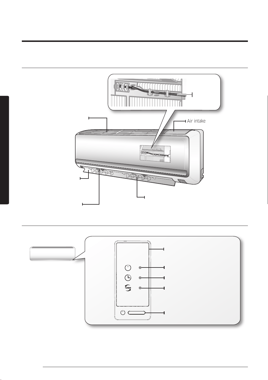
Main parts
Air lter
(under the panel)
Air ow blade
(up and down)
Blade pin lever
Air intake
Air ow blade
(left and right)
Room
temperature
sensor
Display
Turbo indicator
Timer/Auto clean indicator
Power indicator
Power button
Remote controller receiver
The actual product may differ slightly from the image depicted below.
Indoor Unit Overview
At a Glance
13English
At a Glance
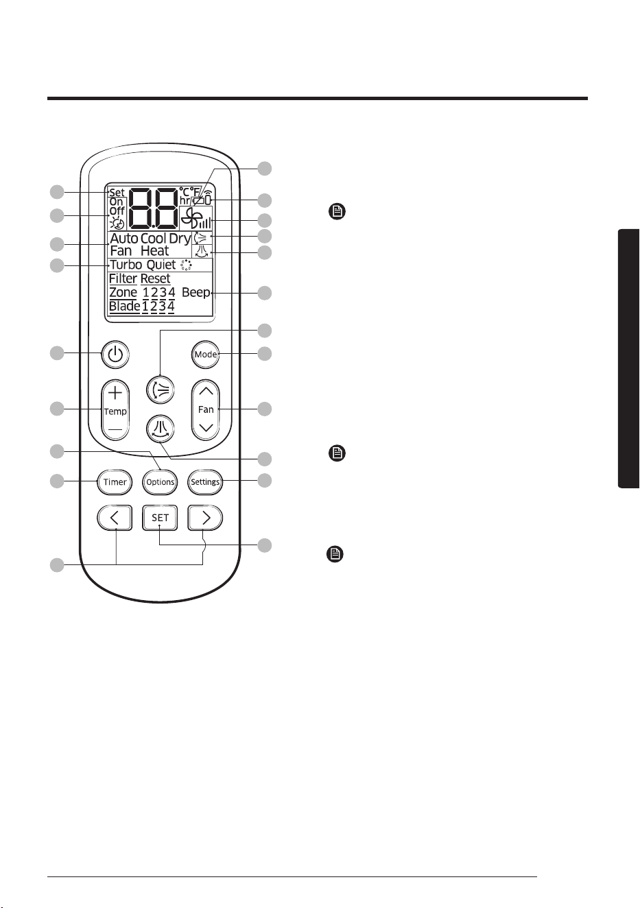
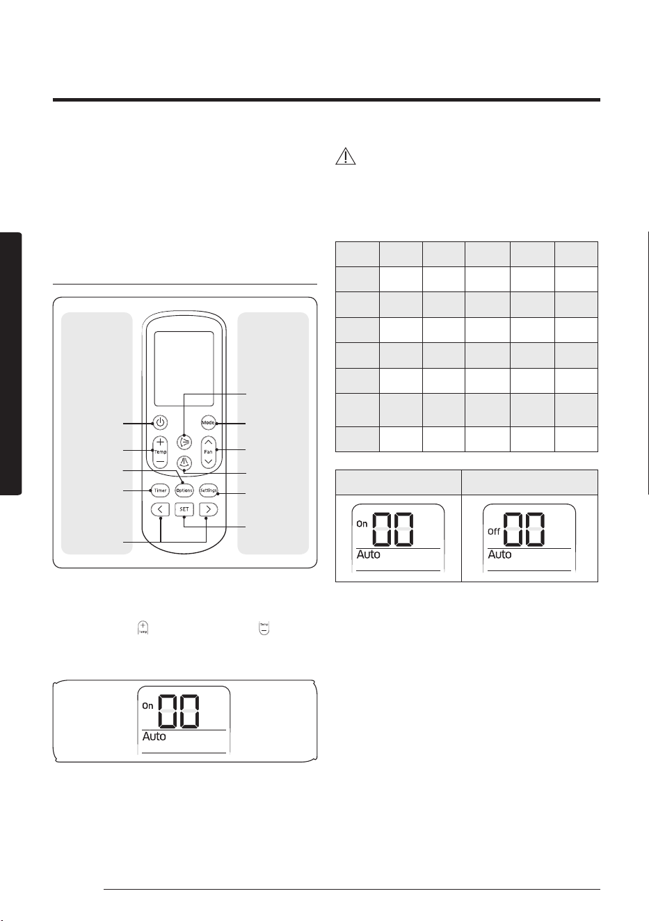
Remote Control Overview
01
05
06
07
08
09
16
17
18
20
21
02
03
04
11
12
13
19
14
15
10
01 Set temperature indicator
02 Timer option indicator
03 Operation mode indicator
04 Options indicator
05 Low battery indicator
06 Transmit indicator
07 Fan speed indicator
08 Vertcal air swing indicator
09 Horizontal air swing indicator
NOTE
• This function is not available in this model.
10 Settings indicator
11 Power button
12 Temperature button
13 Options button
14 Timer button
15 Direction button/Selection button
16 Vertical air swing button
17 Mode button
18 Fan speed button
19 Horizontal air swing button
NOTE
• This function is not available in this model.
20 Settings button
21 SET button
NOTE
• The air conditioner may not be operated by
the remote control if the controller is placed
close to strong light such as a fluorescent
lamp or neon sign. In this case, use the
remote control right in front of the remote
control receiver of the indoor unit.
• If other electrical products are operated by the
remote control, call your nearest service center.
• To silence the beep sound, press the
Settings → <, > or Settings → (Beep)
blinking → SET button. When you press
the Settings → <, > or Settings → (Beep)
blinking → SET button again, the beep
sound will be active again.
At a Glance
14 English
At a Glance
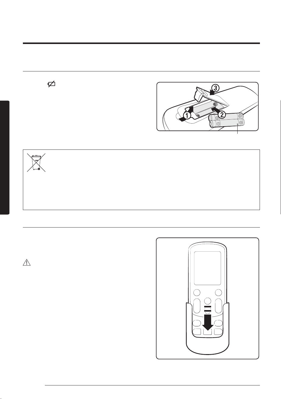
Replacing batteries
When the icon appears in the remote control
display, replace the batteries with new ones. Two
1.5V AAA type batteries are required.
Correct disposal of batteries in this product
(Applicable in countries with separate collection systems)
This marking on the battery, manual or packaging indicates that the batteries in this product should not be
disposed of with other household waste at the end of their working life. Where marked, the chemical symbols Hg,
Cd or Pb indicate that the battery contains mercury, cadmium or lead above the reference levels in EC Directive
2006/66.
Storing the remote control
If the remote control will not be used for an
extended period of time, store it in the remote
control holder with the batteries removed.
CAUTION
• Make sure that water does not come into the
remote control.
two 1.5V AAA type batteries
Remote Control Overview
15English
Basic Operation
Auto
In Auto mode, the air conditioner will automatically adjust
the temperature and fan speed to maintain your fresh
environment.
• When the indoor temperature is too high, the powerful
cool breeze is generated and when the indoor room
becomes cool enough, the soft breeze is generated.
Cool
The Cool mode is frequently used and you can freely control
the temperature, fan speed, and air flow direction in Cool
mode.
• When you select the Heat mode while the Cool mode is on,
the Cool mode is cancelled.
Dry
The air conditioner in Dry mode acts like a dehumidifier by
removing moisture from the indoor air. The Dry mode will
provide you with fresh air even on a rainy day.
Fan
The Fan mode provides you with a breeze just like a fan to
make fresh environment for you.
Basic Operation
Operation Modes
16 English
Basic Operation
Heat
In Heat mode, you can warm your room even in fall and
winter.
• The fan may not commence immediately to avoid
generating a cold breeze.
• In Heat mode, defrost operation may be performed to
remove the frost formed on the outdoor unit. (When the
frost is removed by the defrost operation in Heat mode,
steam is generated from the outdoor unit.)
• If you stop operating the air conditioner after heating
operation, the fan will operate for some time to cool the
indoor unit.
• When you select the Cool mode while the Heat mode is on,
the Heat mode is cancelled.
NOTE
• When the outdoor temperature is relatively low and the
humidity is relatively high in Heat mode, the outdoor unit's
heating capacity may decrease due to the frost formed on
the outdoor heat exchanger. The defrost operation removes
the frost formed on the heat exchanger of the outdoor unit
for 5 to 12 minutes. During the defrost operation, the indoor
unit does not generate breeze in order to prevent cold breeze
blowing out.
– The interval between defrost operations can decrease
depending on the amount of the frost formed on the
outdoor unit.
– The interval between defrost operations can also decrease
depending on the humidity level in the air.
Operation Modes
17English
Basic Operation
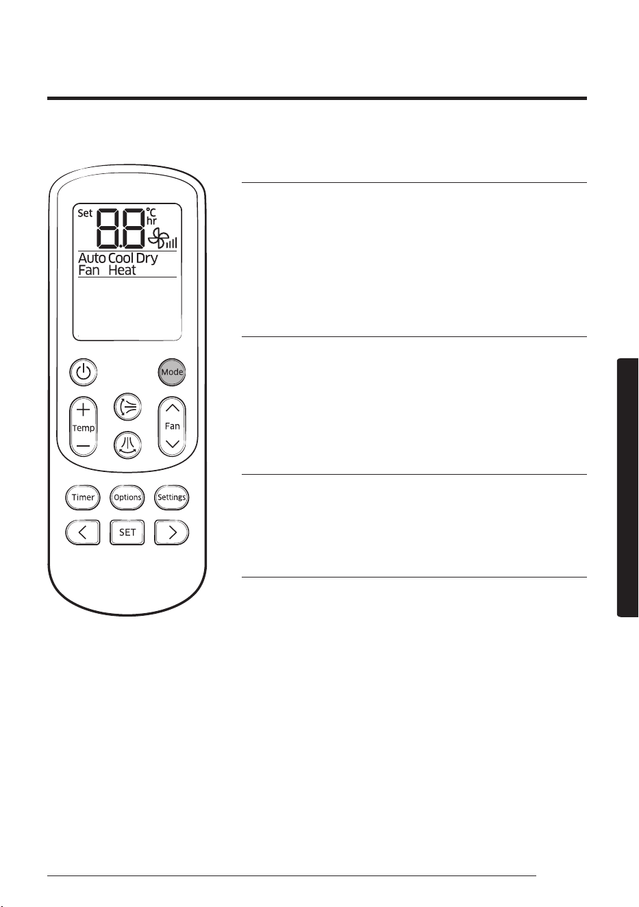
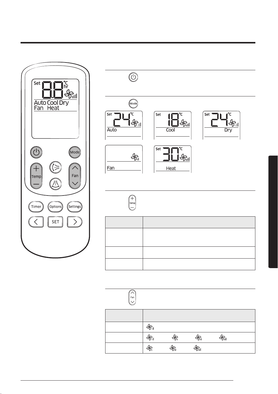
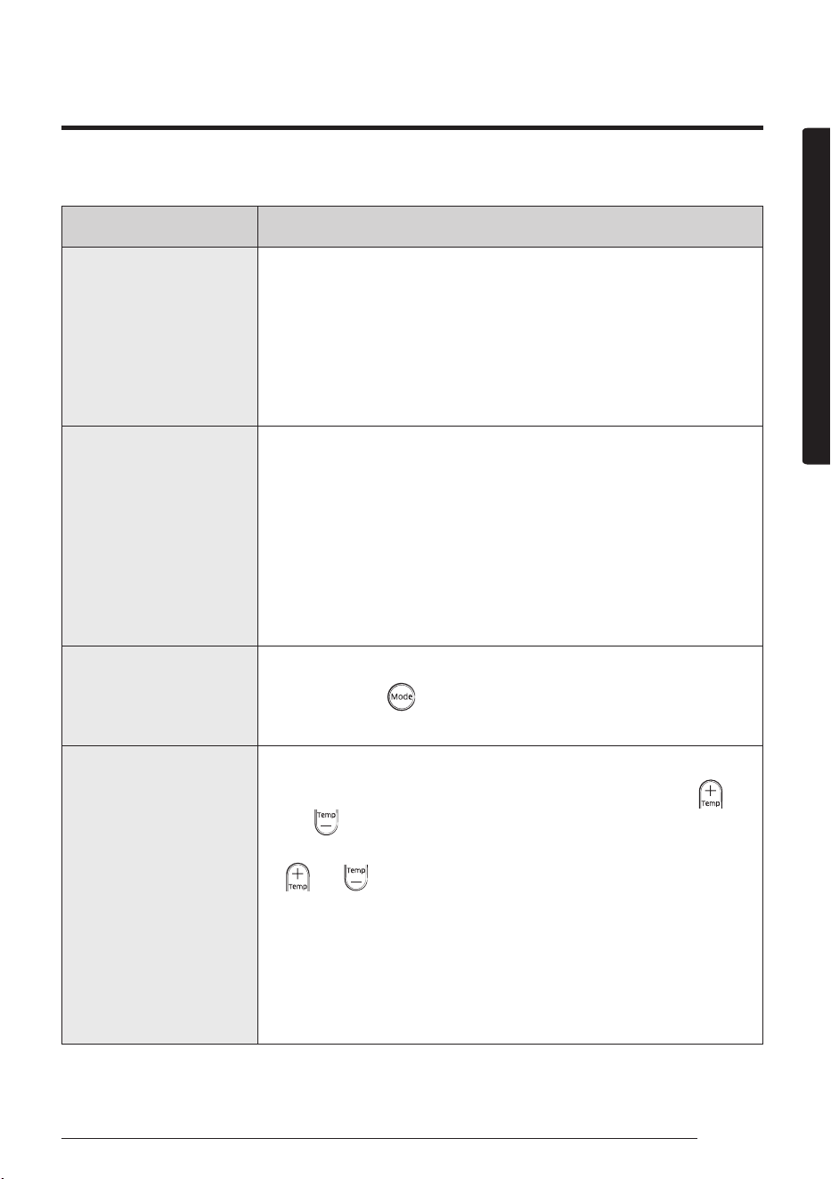
Turning the air conditioner on
Press the button to operate the air conditioner.
Selecting the operation mode
Press the button to select an operation mode.
► ► ►
►
Adjusting the temperature
Press the button to adjust the temperature.
Mode Temperature control
Auto/Cool/
Dry
Adjust by 1 °C between 18 °C and 30 °C.
Heat Adjust by 1 °C between 16 °C and 30 °C.
Fan Temperature cannot be adjusted.
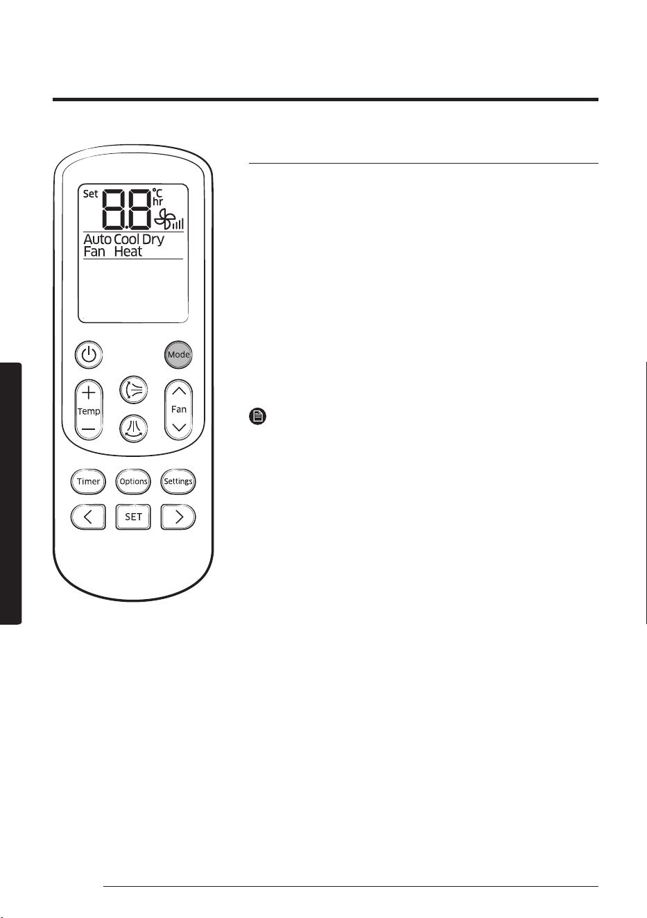
Selecting the fan speed
Press the button to adjust the fan speed.
Mode Available fan speeds
Auto/Dry
(Auto)
Cool/Heat
(Auto), (Low), (Med), (High)
Fan
(Low), (Med), (High)
Basic Operation
18 English
Basic Operation
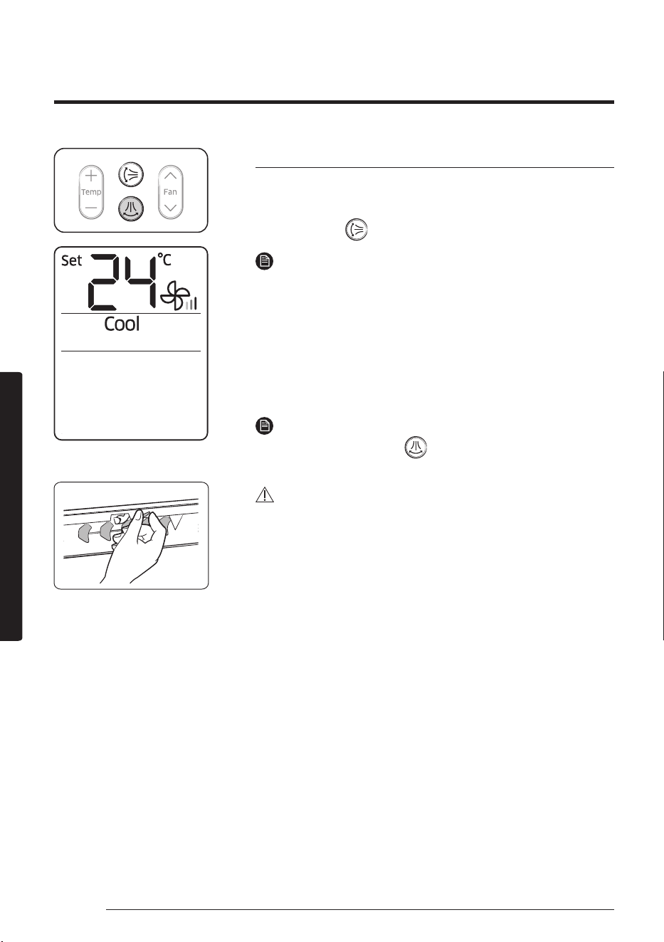
Selecting air flow direction
Keep the air flow in a constant direction by stopping the
movements of the vertical and horizontal air flow blades.
In operation ►
NOTE
• If you adjust the vertical air flow blade manually, it may not
close completely when you turn off the air conditioner.
Horizontal air flow (manual)
Keep the horizontal air flow in a constant direction by
changing the directions of the horizontal air flow blades
manually.
NOTE
• Although you press the
button, this function does not
work.
CAUTION
• To prevent personal injury, make sure that you change the
directions of the horizontal air flow blades after stopping the
movements of the vertical air flow blade.
Remote control display
Basic Operation
19English
Advanced Operation
Setting the On or Off timer
Advanced Operation
You can set the air conditioner to be turned on or off automatically at the desired time.
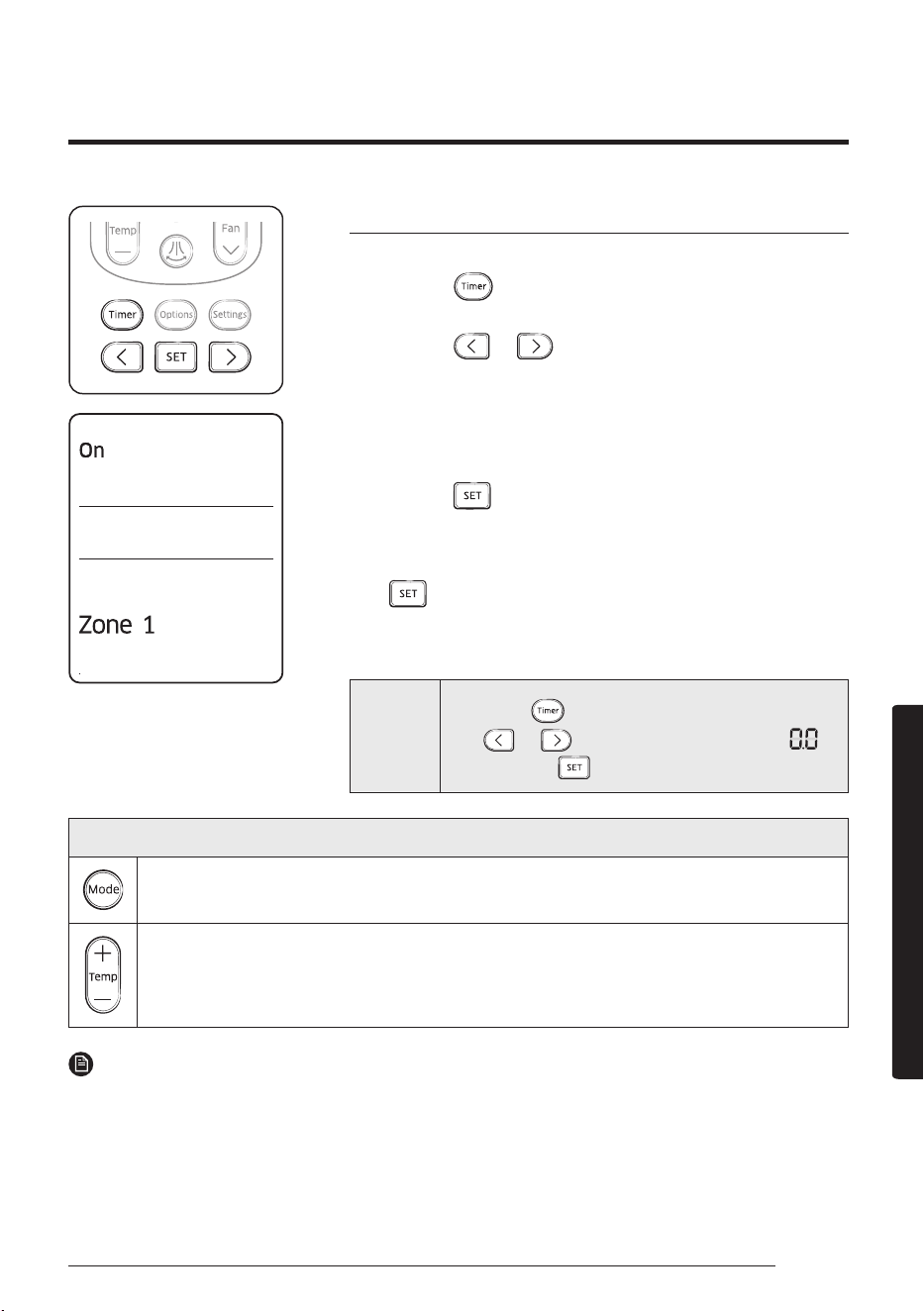
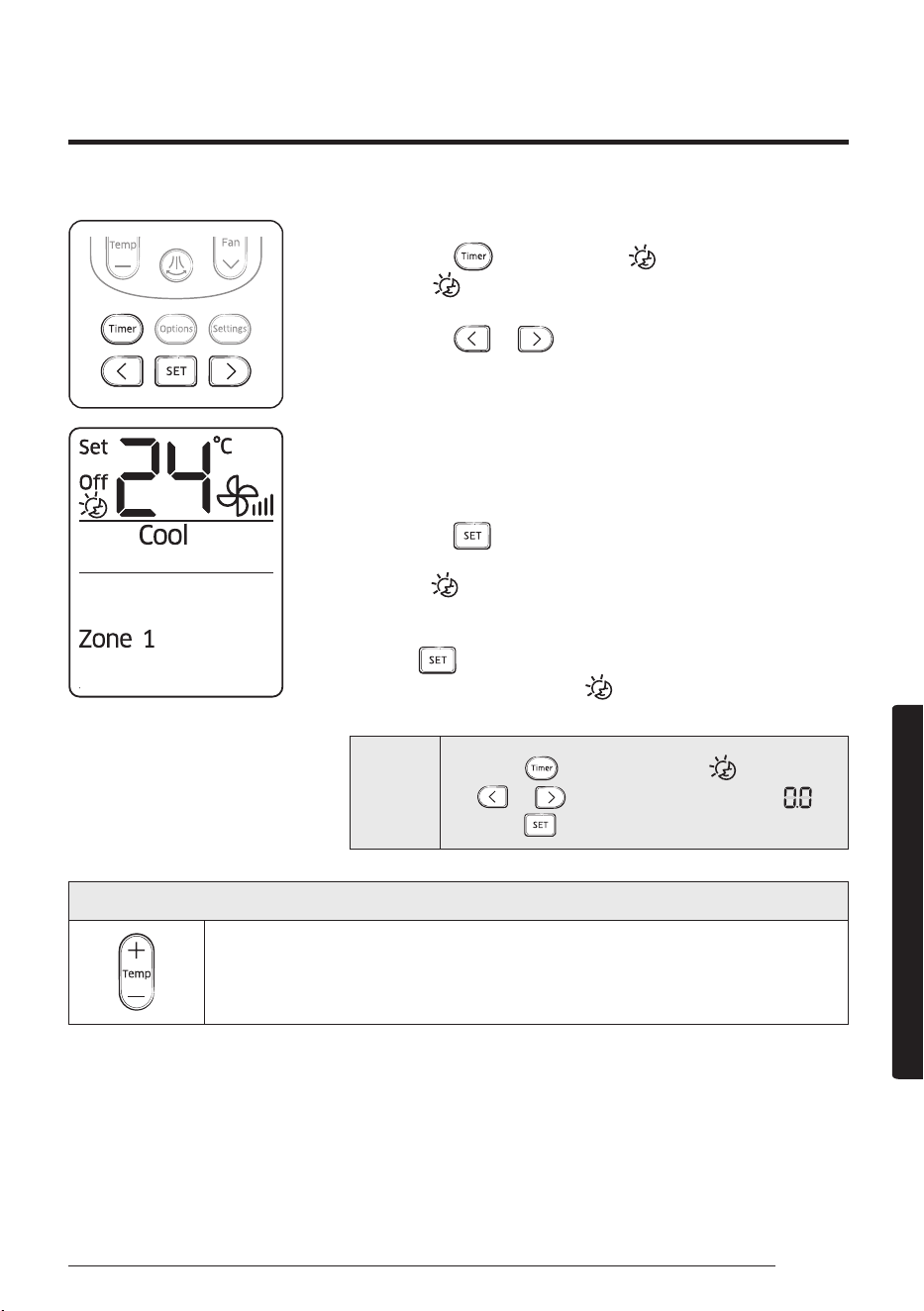
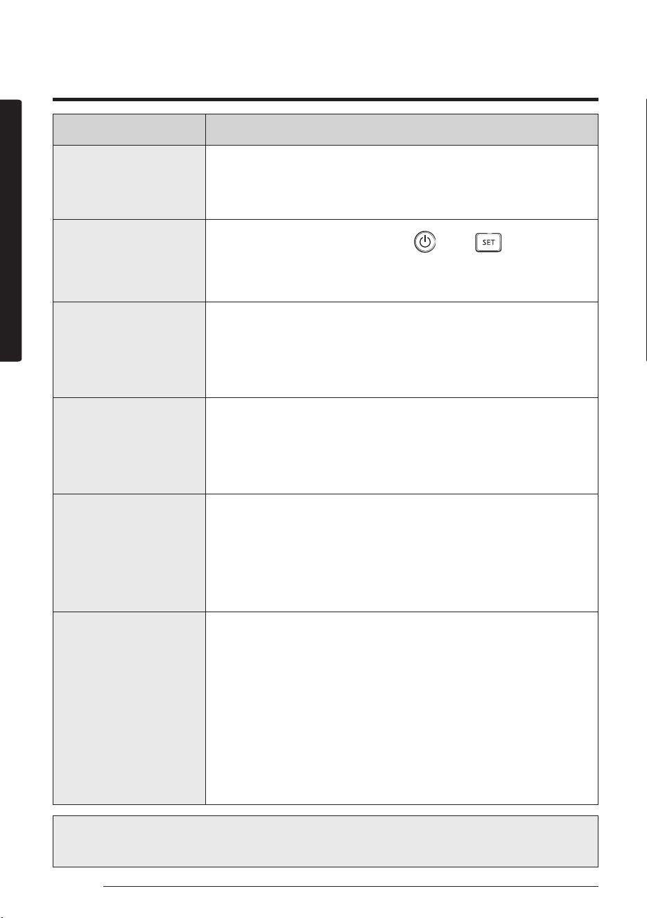
Setting the On timer
When the air conditioner is turned off:
1. Press the button to select (On).
• The (On) indicator will keep blinking and you can set the time.
2. Press the or button to set the time.
• You can set the time in half hour intervals from
30minutes (0.5 on the display) to 3in hour intervals
from 3 to 24 hours.
• The time can be set from minimum 30 minutes to
maximum 24hours.
3. Press the button to complete the On timer setting.
• The (On) indicator and the set time of the timer will be
displayed on the remote control display.
• On timer setting will be cancelled if you don't press the
button within 10seconds after setting the time.
Therefore, check for the (On) indicator on the remote
control display.
Cancel
Press the button ► select (On) ► press
the or button ► set the timer to
► press the button
Remote control display
Additional options available in the On timer
Select the mode in the following order: (Auto) ► (Cool) ► (Dry) ► (Fan) and ► (Heat).
You can adjust the temperature after timer setting is completed.
Temperature adjustment is only available in Auto, Cool, Dry, and Heat modes. In Fan
mode, the temperature cannot be adjusted.
NOTE
• When On timer setting is completed, the setting will be displayed for 3 seconds, and then only the
(On) indicator will remain on the remote control display.
• You cannot set the Fan speed when setting the On timer.
20 English
Advanced Operation
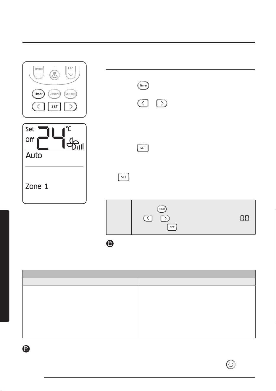
Setting the Off timer
When the air conditioner is turned on:
1. Press the button to select (Off).
• The (Off) indicator will keep blinking and you can set the time.
2. Press the or button to set the time.
• You can set the time in half hour intervals from
30minutes (0.5 on the display) to 3 hours and in hour
intervals from 3 to 24 hours.
• The time can be set from minimum 30 minutes to
maximum 24 hours.
3. Press the button to complete the Off timer setting.
• The (Off) indicator and the set time of the timer will be
displayed on the remote control display.
• Off timer setting will be cancelled if you don't press the
button within 10seconds after setting the time.
Therefore, check for the (Off) indicator on the remote
control display.
Cancel
Press the button ► select (Off) ► press
the or button ► set the timer to
► press the button
NOTE
• Only the latest timer setting will be applied between the Off
timer and good’ sleep off timer functions.
Remote control display
Combining On timer and Off timer
When the air conditioner is turned off When the air conditioner is turned on
When the set time on On timer is less than that on
Off timer
e.g. On timer: 3hours, Off timer: 5hours
• The air conditioner will be turned on after
3hours from the moment you have set the
timer and the air conditioner will remain on for
2hours and then be turned off automatically.
When the set time on On timer is greater than that
on Off timer
e.g. On timer: 3hours, Off timer: 1hour
• The air conditioner will be turned off after
1hour from the moment you have set the
timer and will be automatically turned on after
2hours from the moment it was turned off.
NOTE
• The set times for the On timer and the Off timer should be different from each other.
• After the On timer or the Off timer is set, the setting can be cancelled by pressing the button.
Setting the On or Off timer
21English
Advanced Operation
When the air conditioner is operating in Cool mode;
1. Press the button to select .
• The
(
)
indicator will keep blinking and you can set the
time.
2. Press the or button to set the time.
• You can set the time in half hour intervals from
30minutes (0.5 on the display) to 3 hours and in hour
intervals from 3 to 12 hours.
• The time can be set from minimum 30minutes to
maximum 12hours.
• The default time value for the good'sleep mode is
8hours.
3. Press the button to complete the good'sleep mode
setting.
• The ( ) indicator and the set time of the good'sleep
mode will be displayed on the remote control display.
• The good'sleep mode will be cancelled if you don't press
the button within 10seconds after setting the time.
Therefore, check for the ( ) indicator on the remote
control display.
Cancel
Press the button ► select ( ) ► press
the or button ► set the timer to ►
press the button
Remote control display
Additional options available in good'sleep mode
The temperature can be adjusted by 1°C (1°F) within the range of
18°C (65°F) to 30°C (86°F).
Using the good’sleep Function
22 English
Advanced Operation
For a comfortable sleep, the air conditioner will operate in order of ‘Fall asleep ► Sound sleep ►
Wake up’ stages.
Using the good’sleep Function
• Fall asleep mode: Provides you with comfortable environment for a good sleep by rapid
cooling and hypnagogue expedition breeze.
• Sound sleep mode: The sound sleep mode adjusts temperature and air flow in waves to
maintain healthy skin temperature while it aids deep sleep. According to the change of good’
sleep operation hours, the sound sleep hour can increase or decrease.
• Wake up from good’sleep mode: Provides you with the air flow that adjusts your body
temperature to wake you up in a fresh status.
NOTE
• In good'sleep mode, the air conditioner will operate in Cool + ( ) mode for first 30 minutes.
The fan speed and air flow direction will be adjusted automatically in good'sleep mode.
• Recommended set temperature is between25 °C (77°F) and 27°C (81°F) and the value 26 °C
(79 °F) is the most ideal temperature.
• If the set temperature is too low, you may feel cold while sleeping or catch a cold.
• Optimal operation time in good'sleep mode is 8 hours. Therefore, if the time is set too short
or long, you may not feel as comfortable as you want.
• If the good'sleep mode is set over 5 hours, The Wake up stage will begin when 1 hour is
remaining in the operation time and the air conditioner will stop automatically.
• When the On timer and the good'sleep mode are set simultaneously, the air conditioner will
only apply the function that was set later.
• While the good'sleep mode is operating, the mode can be set additionally by pressing the
button.
• If you press the button and select the Turbo/Quiet function, the good'sleep mode will be
cancelled and the selected mode will begin operation.
• If you press the button, the good'sleep mode will be cancelled and the selected mode wi
ll
begin operation.
23English
Advanced Operation
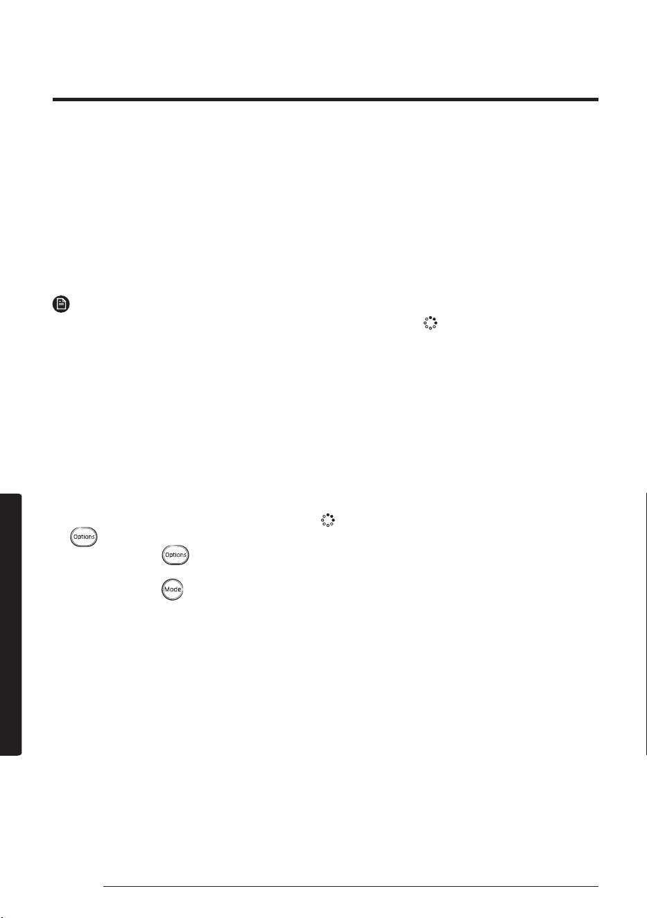
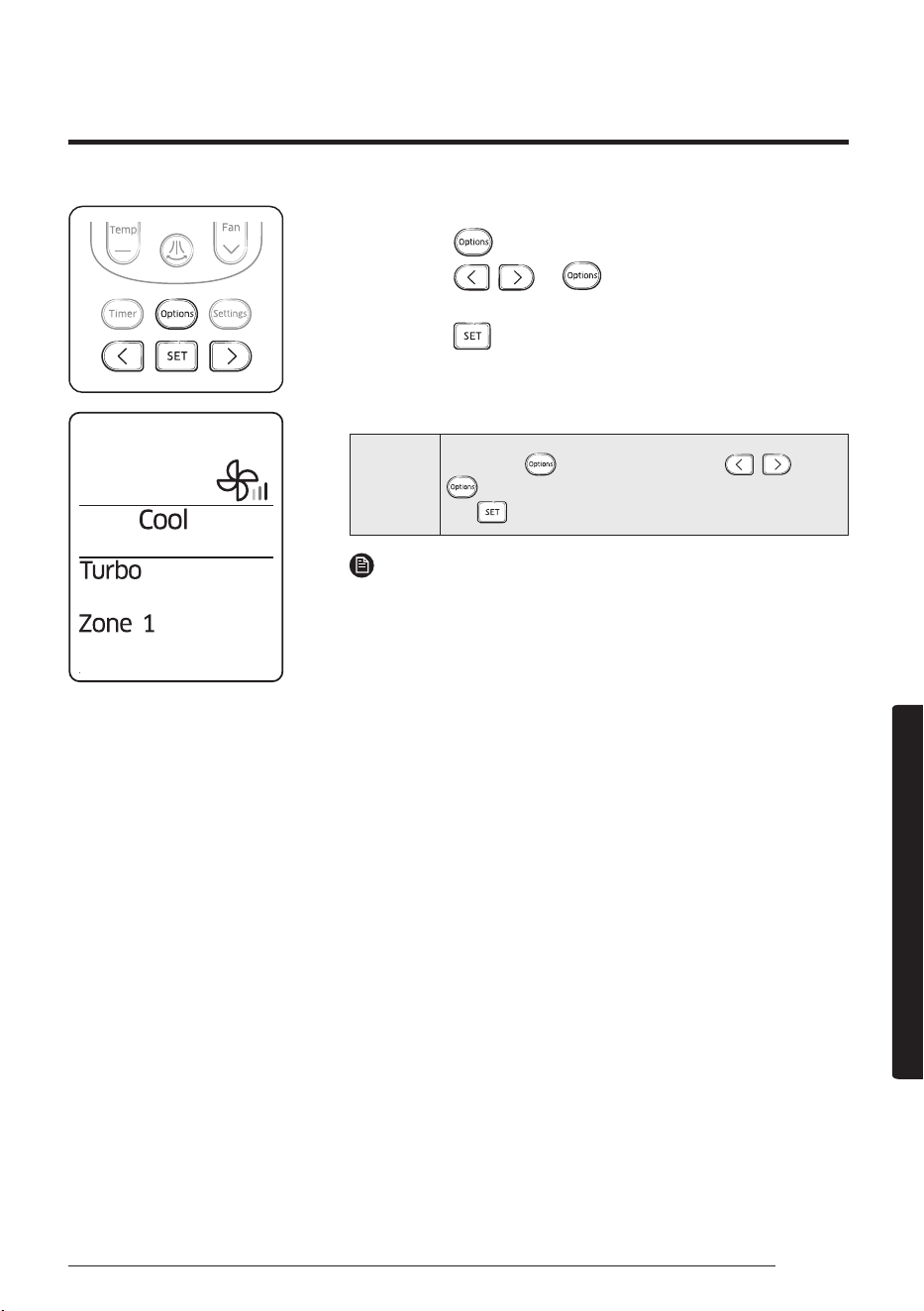
When the air conditioner is operating in Cool mode;
1. Press the button.
2. Press the , or button until the (Turbo)
indicator starts blinking.
3. Press the button to set the Turbo function.
• The (Turbo) indicator will be displayed on the remote
control display and Turbo function will operate for
30 minutes.
Cancel
Press the button ► press the , or
to make the (Turbo) indicator blink and press
the button.
NOTE
• Turbo function is available in Cool or Heat mode.
• If the Turbo function is selected while the Quiet function is
on, the Quiet function will be cancelled.
• The temperature and fan speed cannot be adjusted.
Remote control display
Using the Turbo Function
You can set the Turbo function to provide fast and powerful cooling.
24 English
Advanced Operation
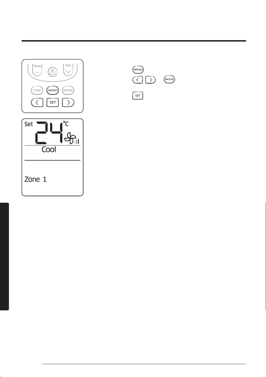
You can individually select and operate indoor units among 4 indoor units.
Controlling Indoor Units
When the air conditioner is turned on:
1. Press the button.
2. Press the , or button until the (Zone)
indicator starts blinking.
3. Press the button to select the indoor unit to operate.
• You can select individual units in order of 1 to 4 or select
all indoor units at one time.
Remote control display
25English
Cleaning and Maintenance
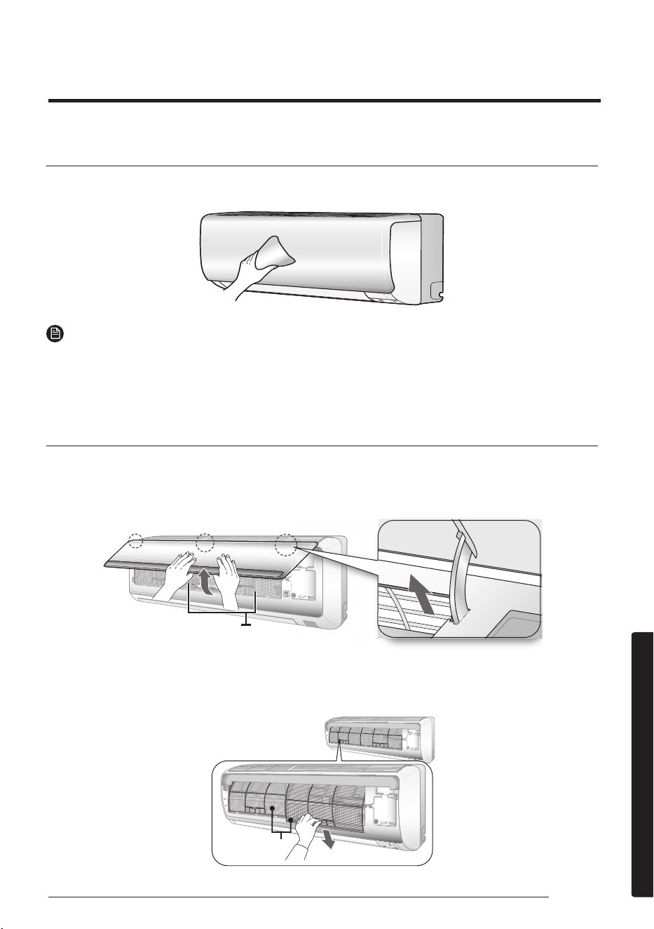
Cleaning the exterior
Wipe the surface of the unit with a slightly wet or dry cloth when needed.
NOTE
• Do not use sulphuric acid, hydrochloric acid, or organic solvents (such as thinner, kerosene,
and acetone) to clean the surfaces.
• Do not put any stickers on it as this can damage the surface of the air conditioner.
Disassembling the air filter
1. Opening the panel
Tightly grab top of the front panel and pull it down to open. Then slightly lift the panel up.
Air lter
2. Removing the Air lter
Grab the handle and lift it up. Then pull the Air lter towards you and slide it down.
Air filter
Air lter
Cleaning and Maintenance
Cleaning the Air Conditioner
26 English
Cleaning and Maintenance
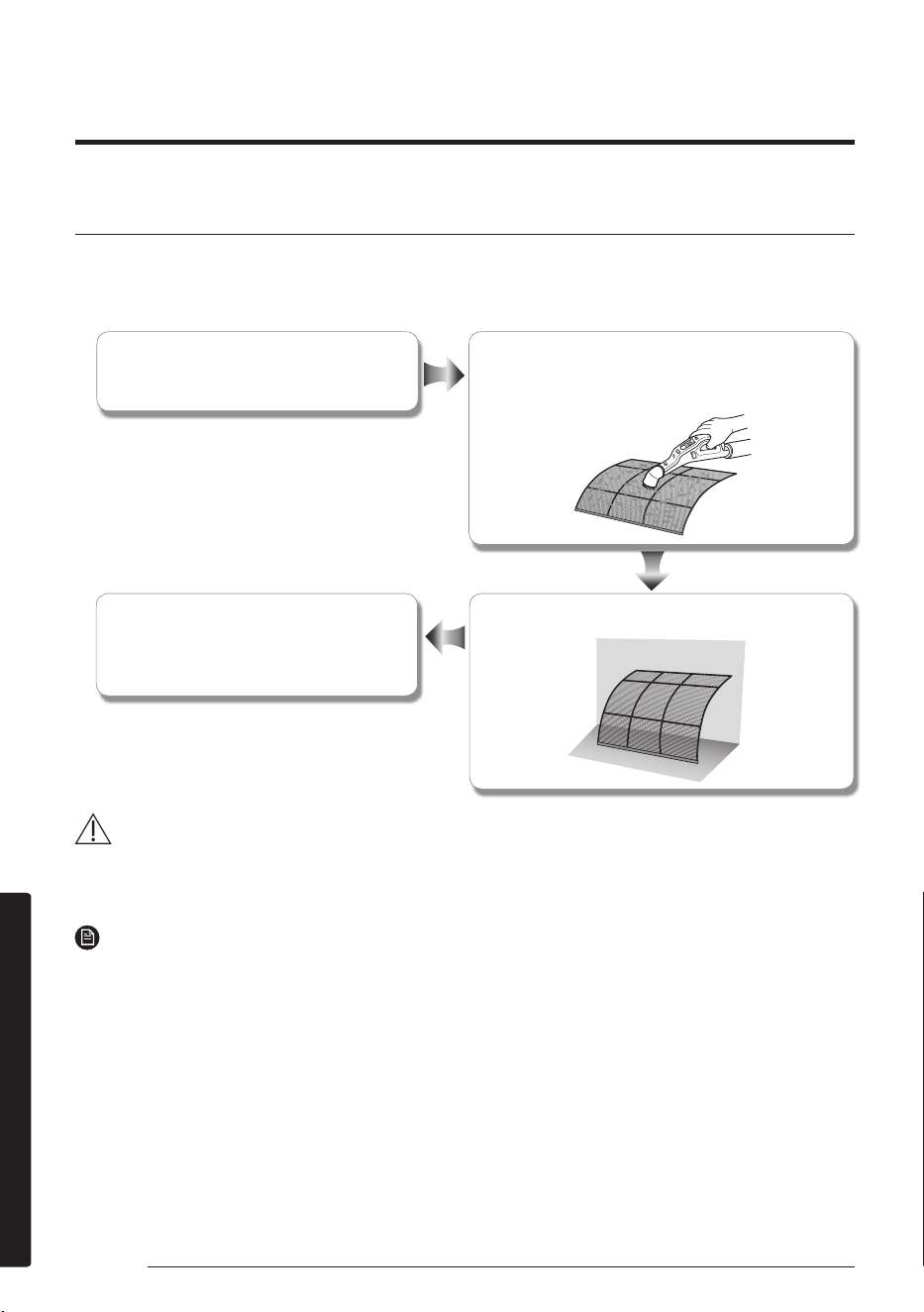
Cleaning the air filter
Washable foam based air lter captures large particles from the air. The lter is cleaned with a
vacuum or by hand washing.
Open the panel and put the Air lter out.
Insert the Air lter back in its original
position and close the front panel.
Dry the Air lter in a ventilated area.
Clean the Air lter with a vacuum cleaner or
soft brush. If dust is too heavy, rinse it with
running water.
CAUTION
• Do not scrub the air filter with a brush or other cleaning utensil. This may damage the filter.
• Do not expose the air filter to direct sunlight when drying it.
NOTE
• Clean the air filter every 2 weeks. Cleaning term may vary depending on the usage and
environmental conditions.
• If the air filter dries in a humid area, it may produce offensive odours. Clean it again and dry
it in a well-ventilated area.
Cleaning the Air Conditioner
27English
Cleaning and Maintenance
Maintaining the Air Conditioner
If the air conditioner will not be used for an extended period of time, dry the air conditioner to
maintain in best conditions.
1. Dry the air conditioner thoroughly by operating in Fan mode for 3 to 4 hours and disconnect
the power plug. There may be internal damage if moisture is left in components.
2. Before using the air conditioner again, dry the inner components of the air conditioner again
by running in Fan mode for 3 to 4 hours. This helps remove odours that may have generated
from dampness.
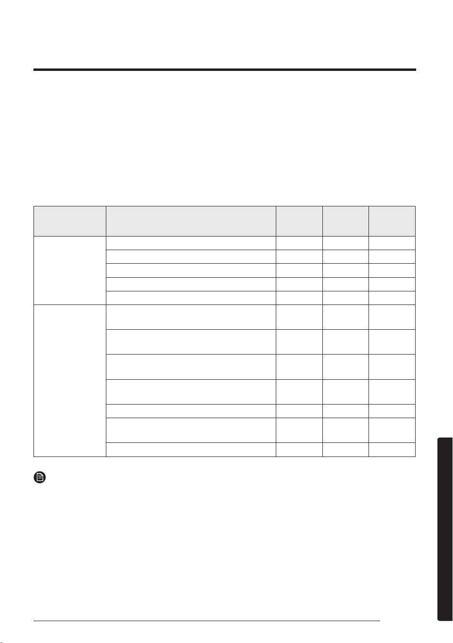
Periodical checks
Refer to the following chart to maintain the air conditioner properly.
Type Description Monthly
Every 4
months
Once a
year
Indoor unit
Clean the air filter (1).
l
Clean the condensate drain pan (2).
l
Thoroughly clean the heat exchanger (2).
l
Clean the condensate drain pipe (2).
l
Replace the remote control batteries (1).
l
Outdoor unit
Clean the heat exchanger on the outside
of the unit (2).
l
Clean the heat exchanger on the inside of
the unit (2).
l
Clean the electric components with jets
of air (2).
l
Verify that all the electric components
are firmly tightened (2).
l
Clean the fan (2).
l
Verify that all the fan assembly is firmly
tightened (2).
l
Clean the condensate drain pan (2).
l
NOTE
• The checks and maintenance operations described above are essential to guarantee the
efficiency of the air conditioner. The frequency of these operations may vary depending on
the characteristics of the area, the amount of dust, etc.
a. The above mentioned operations should be performed more frequently if the area of
installation is very dusty.
b. These operations must always be performed by qualified personnel. For more detailed
information, refer to Installation Manual.
28 English
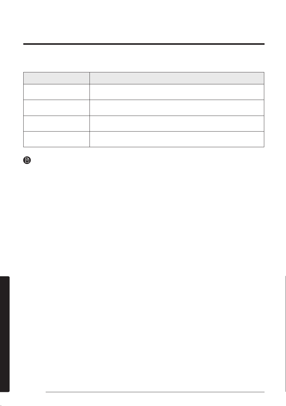
Cleaning and Maintenance
This internal protection operates if an internal fault occurs in the air conditioner.
Type Description
Against cold air
The internal fan will be off against cold air when the heat pump is
heating.
De-ice cycle
The internal fan will be off against cold air when the heat pump is
heating.
Anti-protection of
internal battery
The compressor will be off to protect internal battery when the air
conditioner operates in Cool mode.
Protect compressor
The air conditioner does not start operating immediately to protect
the compressor of the outdoor unit after it has been started.
NOTE
• If the heat pump is operating in Heat mode, the de-ice cycle is actuated to remove frost from
an outdoor unit that may have deposited at low temperatures.
• The internal fan is switched off automatically and restarted only after the de-ice cycle is
completed.
• When the de-ice cycle is operating,it may generate strange sound. It is normal operation for
product safety.
Internal protections via the unit control system
Maintaining the Air Conditioner
29English
Appendix
Troubleshooting
Refer to the following chart if the air conditioner operates
abnormally. This may save time and unnecessary expenses.
Appendix
Problem Solution
The air
conditioner does
not operate
immediately
after it has been
restarted.
• Because of the protective mechanism,
the appliance does not start operating
immediately to keep the unit from
overloading.
The air conditioner will start in 3 minutes.
The air
conditioner does
not work at all.
• Check that the power plug is properly
connected. Insert the power plug into the
wall socket correctly.
• Check if the circuit breaker is switched off.
• Check if there is a power failure.
• Check your fuse. Make sure it is not blown
out.
The temperature
does not change.
• Check if you selected Fan mode.
Press the button on the remote control to
select another mode.
The cool (or warm)
air does not come
out of the air
conditioner.
• Check if the set temperature is higher (lower)
than the current temperature. Press the
or button on the remote control to change
the set temperature. Press the Temperature
or button to increase or decrease the
temperature.
• Check if the air filter is blocked by dirt. Clean
the air filter every two weeks.
• Check if the air conditioner has just been
turned on. If so, wait for 3 minutes.
30 English
Appendix
Problem Solution
The fan speed
does not change.
• Check if you selected Auto or Dry mode.
The air conditioner automatically adjusts the
fan speed to Auto in Auto/Dry mode.
Timer function
is not set.
• Check if you press the and button on
the remote control after you have set the
time.
Odours
permeate in the
room during
operation.
• Check if the appliance is running in a smoky
area or if there is a smell entering from
outside. Operate the air conditioner in Fan
mode or open the windows to air out the room.
The air
conditioner
makes a
bubbling sound.
• A bubbling sound may be heard when
the refrigerant is circulating through the
compressor. Let the air conditioner operate
in the selected mode.
Water is
dripping from
the air flow
blades.
• Check if the air conditioner has been
cooling for an extended period of time with
the air flow blades pointed downwards.
Condensation may generate due to the
difference in temperature.
Remote control
is not working.
• Check if your batteries are depleted.
• Make sure batteries are correctly installed.
• Make sure nothing is blocking your remote
control sensor.
• Check that there are strong lighting
apparatus near the air conditioner. Strong
light that comes from fluorescent bulbs or
neon signs may interrupt the electric waves.
To perform its antimicrobial function this product has been treated
with the biocide substance Silver zinc zeolite.
Troubleshooting
31English
Appendix
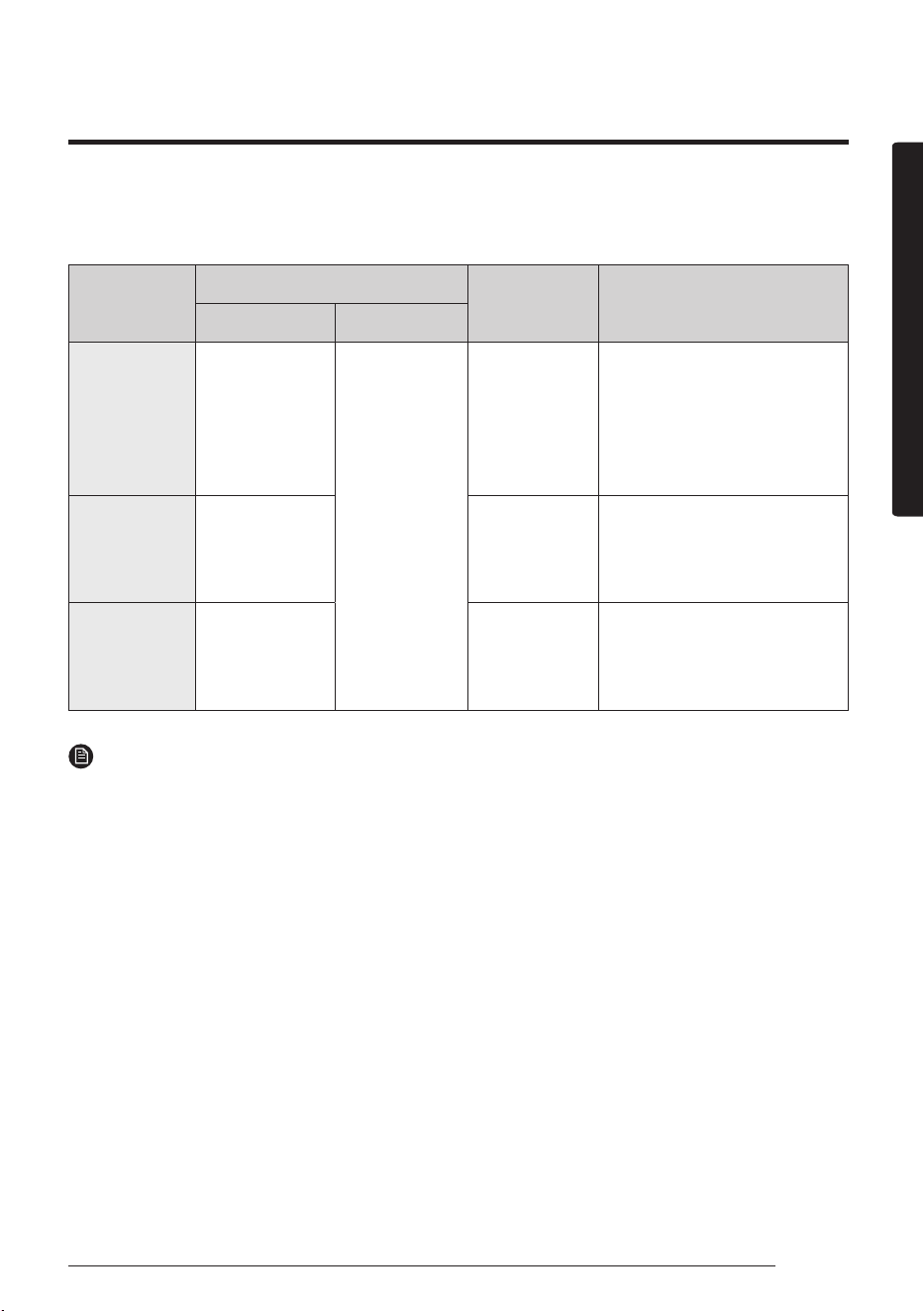
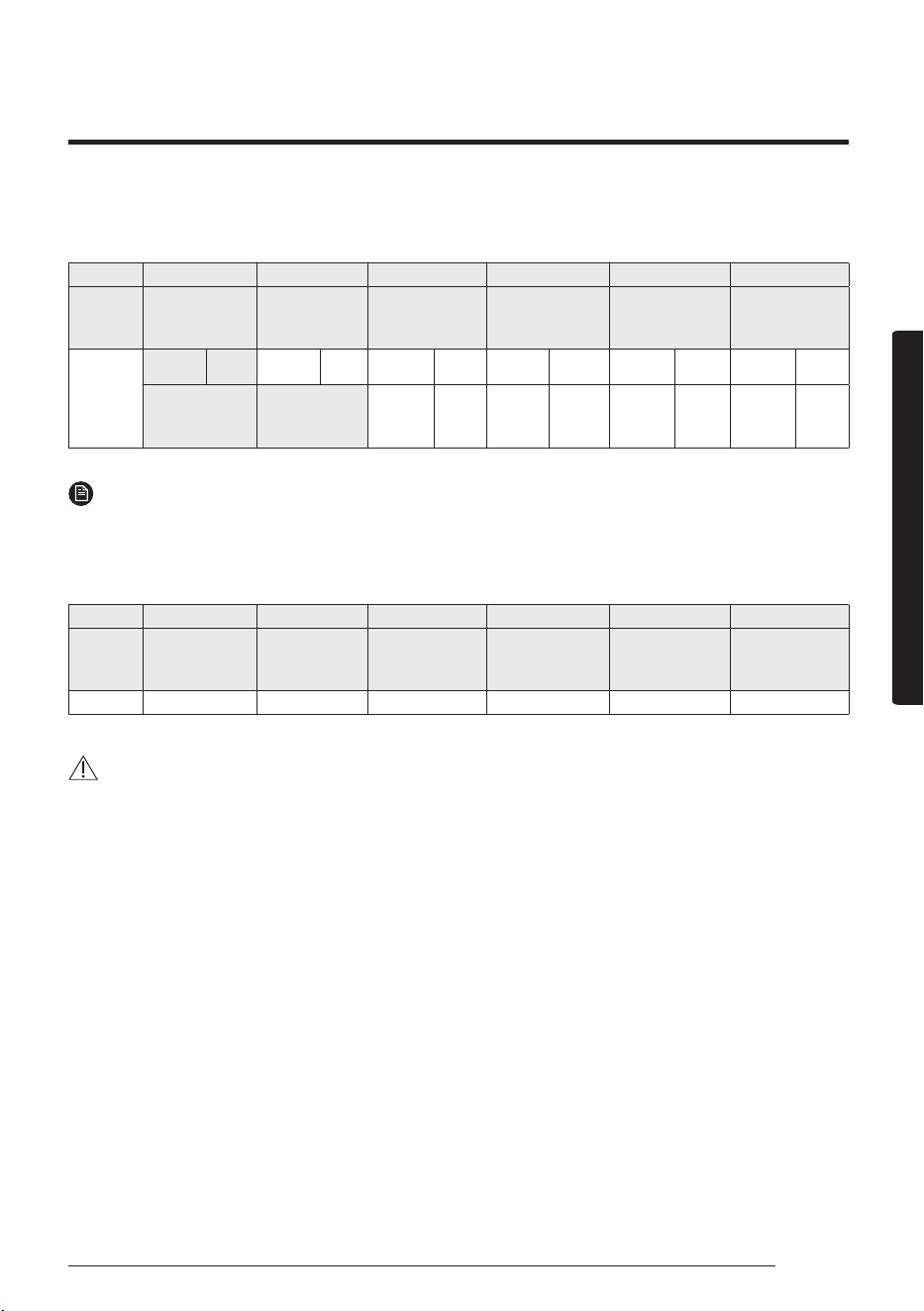
The table below indicates the temperature and humidity ranges the air conditioner can be
operated within. Refer to the table for efficient use.
MODE
OPERATIONAL TEMPERATURE
INDOOR
HUMIDITY
IF OUT OF CONDITIONS
INDOOR OUTDOOR
COOLING 18 ˚C to 32 ˚C
Depends
on the
specifications
of the outdoor
unit.
80 % or less
Condensation may occur on
the indoor unit with risk to
have either water blow off or
drops on the floor.
HEATING 27 ˚C or less -
Internal protection triggers
and the air conditioner will
stop.
DRYING 18 ˚C to 32 ˚C 80 % or less
Condensation may occur on
the indoor unit with risk to
have either water blow off or
drops on the floor.
NOTE
• The standardized temperature for heating is 7 ˚C. If the outdoor temperature drops to 0 ˚C or
below, the heating capacity can be reduced depending on the temperature condition.
• If the cooling operation is used at over 32˚C (indoor temperature), it does not cool at its full
capacity.
Operation Ranges
32 English
Appendix
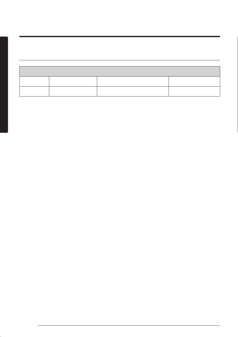
Model specification (Dimension and weight)
Dimension and weight
Type Model Net dimension (WxDxH) (mm) Net weight (kg)
Indoor unit AM093MNQDEH 1280*253*345 18.5
Technical specification
33English
Installation part
Installation Procedure
Installing the indoor unit
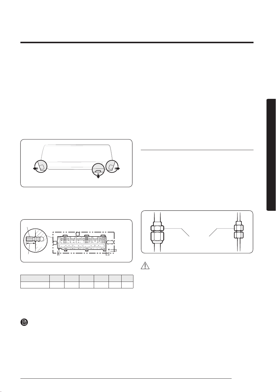
Before fixing the installation plate to the wall or window
frame, you must determine the position of the 65mm hole
through which the cable, pipe and hose pass to connect
the indoor unit to the outdoor unit.
When facing the wall, the pipe and cable can be connected
from the:
• Right
• Left
• Underside (right)
• Rear (right or left)
RightLeft
Underside
1
Determine the position of the pipe and drain hose
hole as seen in the picture and drill the hole with an
inner diameter of 65mm so that it slants slightly
downwards.
Wall
20 mm
Plastic anchor
A
C
B
D
F E
Pipe bundle hole
Pipe bundle hole: Ø 65 mm (Unit : mm)
Model A B C D E F
AM093MNQDEH 156 67 364 34.5 64.5 19.5
2 If you fix the indoor unit to a wall, fix the installation
plate to the wall giving attention to the weight of the
indoor unit.
NOTE
• If you mount the plate to a concrete wall by using
plastic anchors, make sure that gaps between the wall
and the plate, created by projected anchor, are less
than 20 mm.
3 If you fix the indoor unit to a window frame, follow
4 to 6.
4 Determine the positions of the wooden uprights to be
attached to the window frame.
5 Attach the wooden uprights to the window frame
giving attention to the weight of the indoor unit.
6 Attach the installation plate to the wooden uprights
using tapping screw.
Performing leak test
Leak test
LEAK TEST WITH NITROGEN (before opening valves)
In order to detect basic refrigerant leaks, before recreating
the vacuum and recirculating the R410A, it’s responsible of
installer to pressurize the whole system with nitrogen (using
a pressure regulator) at a pressure above 4.1MPa (gauge).
LEAK TEST WITH R410A (after opening valves)
Before opening valves, discharge all the nitrogen into the
system and create vacuum. After opening valves check
leaks using a leak detector for refrigerant R410A.
Test parts for the
indoor unit
CAUTION
• Discharge all the nitrogen to create a vacuum and
charge the system.
Installation part
34 English
Installation part
Installation Procedure
Wrapping the pipes with the insulation
After checking for gas leaks in the system, insulate the
pipe, hose and cables. Then place the indoor unit on the
installation plate.
1 To avoid condensation problems, place heat-resistant
poly-ethylene foam separately around each refrigerant
pipe in the lower part of the indoor unit.
2 Wrap the refrigerant pipe and the drain hose in the
rear of the indoor unit with the absorbent pad.
NOTE
• Wind the pipe and hose three times to the end of the
indoor unit with the absorbent pad. (20mm interval)
3 Wind the pipe, assembly cable and drain hose with
insulation tape.
4 Place the bundle (the pipe, assembly cable and drain
hose) in the lower part of the indoor unit carefully so it
doesn’t project from the rear of the indoor unit.
Installation plate
5 Hook the indoor unit to the installation plate and move
the unit to the right and left until it is securely in place.
6 Wrap the rest of the pipe with vinyl tape.
7 Attach the pipe to the wall using clamps (optional).
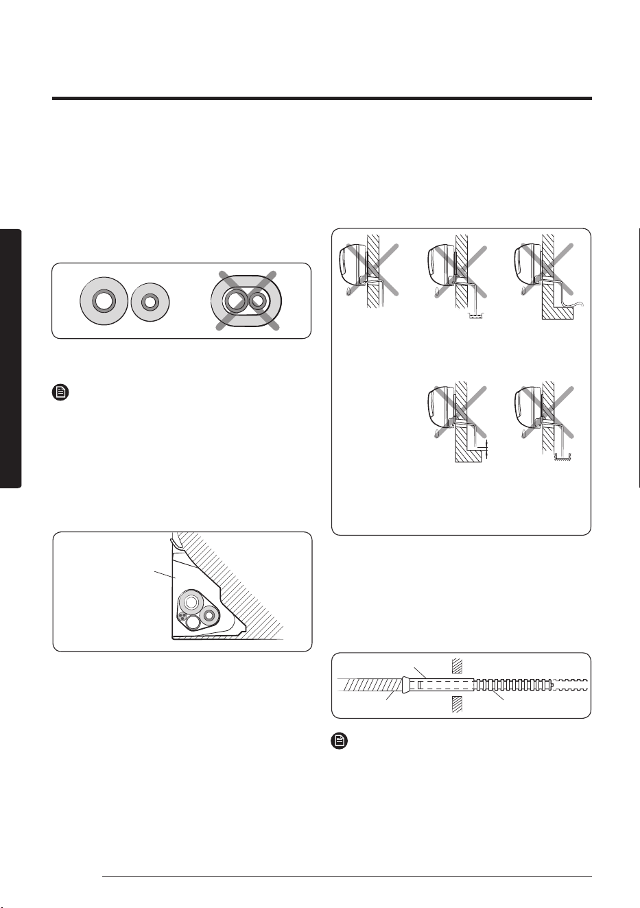
Installing the drain hose
When installing the drain hose for the indoor unit, check if
condensation draining is adequate. When passing the drain
hose through the 65-mm hole drilled in the wall, check the
following:
The hose must
NOT slant
upwards.
5 cm
less
Ditch
The end of the
drain hose must
NOT be placed
under water.
Do NOT bend the
hose in different
directions.
Keep a clearance
of at least 5cm
between the end
of the hose and
the ground.
Do NOT place the
end of the drain
hose in a hollow.
1 If necessary, connect the 2-meter extension drain hose
to the drain hose.
2 If you use the extension drain hose, insulate the inside
of the extension drain hose with a shield.
3 Fit the drain hose into 1 of 2 drain hose holes, then fix
the end of the drain hose tightly with a clamp.
Shield
Drain hose Extension drain hose
NOTE
• If you don’t use the other drain hose hole, block it with
a rubber stopper.
35English
Installation part
4 Pass the drain hose under the refrigerant pipe, keeping
the drain hose tight.
5 Pass the drain hose through the hole in the wall. Check
if it slants downwards as seen in the picture.
NOTE
• The hose will be fixed permanently into position after
finishing the installation and the gas leak test; refer to
page 12 for further details.
• DO NOT WALL UP THE DRAIN HOSE CONNECTION!
Drain hose connection must be easy accessible and
serviceable.
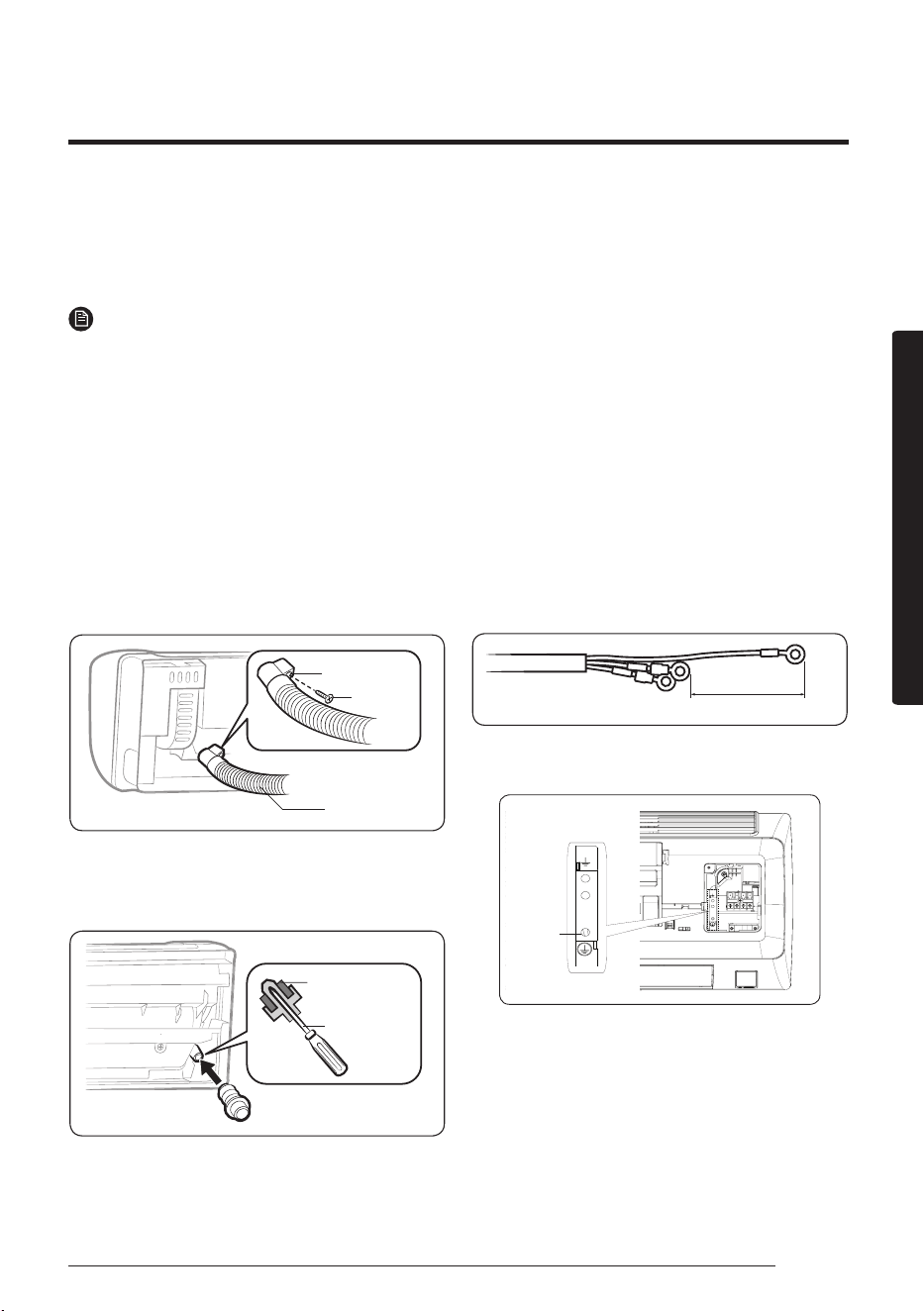
Optional: Changing direction of the
drain hose
You can select the direction of the drain hose, depending
on where you want to install the indoor unit.
1 Detach the rubber cap with the flyer.
Drain hose
Screw hole
Screw
2 Detach the drain hose by pulling it and turning to the left.
3 Insert the drain hose by fixing it into the groove of the
drain hose and the outlet of the drain pan.
Drain pan
outlet
Rubber cap
4 Attach the rubber cap with a screwdriver by turning it
to the right until it fixes to the end of the groove.
Connecting the power and
communication cables
1 Before wiring work, you must turn off all power
source.
2 Indoor unit power should be supplied through the
breaker( ELCB or MCCB+ELB ) separated by the
outdoor power.
• ELCB:Earth Leakage Circuit Breaker
• MCCB:Molded Case Circuit Breaker
• ELB:Earth Leakage Breaker
3 The power cable should be used only copper wires.
4 Connect the power cable{1(L), 2(N)} among the units
within maximum length and communication cable(F1,
F2) each.
5 Cut the cable as like the following picture. The earth
cable need to be longer than the power cable (1(L),
2(N)) by 100 mm.
100mm
6 Connect the earth cable to the plate on the evaporator
as like the following picture.
Power-earth
cable
36 English
Installation part
Installation Procedure
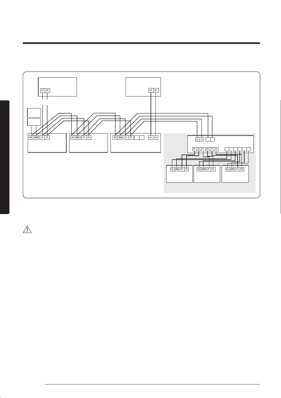
7 Connect F3, F4(for communication) wires at the back side of the indoor unit when installing the wired remote control.
N L
N L N L N L
ELCB
MCCB+
ELB
V1 V2
Outdoor Unit
Indoor Unit 1 Indoor Unit 2 Indoor Unit 3
Indoor Unit 4 Indoor Unit 5 Indoor Unit 6
EEV kit
220-240V~or
Wired Remote
Control
∙ Ceiling, wall-mounted indoor unit.
• ELCB : Essential Installation
• The EEV Kit is optional component.
WARNING
• Power off before connecting any wires;Indoor PBA will be damaged while V1,V2,F3,F4 short each other.
• You must connect the earth cable. If earthing is not complete, electric shock or fire may occur.
37English
Installation part
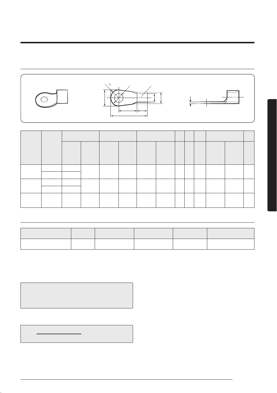
Ring terminal selection
t
R
B
2
d2
d1
D
B
L
F E
Silver solder
Norminal
dimensions
for cable
(mm2)
Norminal
dimensions
for screw
(mm)
B C d1 E F L d2 t
Standard
dimension
(mm)
Allowance
(mm)
Standard
dimension
(mm)
Allowance
(mm)
Standard
dimension
(mm)
Allowance
(mm)
Min. Min. Max.
Standard
dimension
(mm)
Allowance
(mm)
Min.
1.5
4 6.6
±0.2 3.4
+0.3
-0.2
1.7 ±0.2 4.1 6 16 4.3
+0.2
0
0.7
4 8
2.5
4 6.6
±0.2 4.2
+0.3
-0.2
2.3 ±0.2 6 6 17.5 4.3
+0.2
0
0.8
4 8.5
4 4 9.5 ±0.2 5.6
+0.3
-0.2
3.4 ±0.2 6 5 20 4.3
+0.2
0
0.9
Specification of electronic wire
Power supply MCCB ELB or ELCB Power cable Earth cable Communication cable
Max : 242V / Min : 198V XA XA, 30mmA, 0.1 s 2.5mm2 2.5mm2 0.75~1.5mm2
• Refer to the unit nameplate for rating current.
• Decide the capacity of ELCB(or MCCB+ELB) by below formula.
• Power supply cords of parts of appliances for outdoor use shall not be lighter than polychloroprene sheathed flexible
cord.
(Code designation IEC:60245 IEC 57 / CENELEC: H05RN-F or IEC:60245 IEC 66 / CENELEC: H07RN-F )
The capacity of ELCB(or MCCB+ELB) X[A] = 1.25 X 1.1 X ∑Ai
– X : The capacity of ELCB(or MCCB+ELB).
– ∑Ai : Sum of Rating currents of each indoor unit.
– Refer to each installation manual about the rating
current of indoor unit.
• Decide the power cable specification and maximum length within 10% power drop among indoor units.
n
Coef×35.6×Lk×ik
) < 10% of input voltage[V]
– coef: 1.55
– Lk: Distance among each indoor unit[m],
Ak: Power cable specification[mm2]
ik: Running current of each unit[A]
∑ (
1000×A
k
k=1
38 English
Installation part
Installation Procedure
Setting an indoor unit address and
installation option
Set the indoor unit address and installation option with remote
control option. Set the each option separately since you cannot
set the ADDRESS setting and indoor unit installation setting
option at the same time. You need to set twice when setting
indoor unit address and installation option.
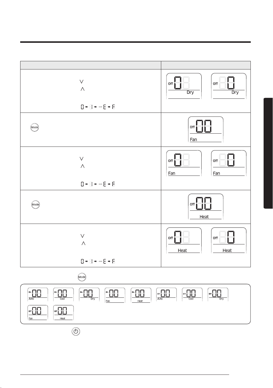
Option setting procedure
1 Remove batteries from the remote control.
2 Insert batteries and enter the option setting mode
while pressing
(High Temp button) and (Low
Temp button).
3 Check if you have entered the option setting status.
4 After entering the option setting status, select the
option.
CAUTION
• Option setting is available from SEG1 to SEG 24
• SEG1, SEG7, SEG13, SEG19 are not set as page option.
• Set the SEG2~SEG6, SEG8~SEG12 as ON status and
SEG14~18, SEG20~24 as OFF status.
SEG1 SEG2 SEG3 SEG4 SEG5 SEG6
0 X X X X X
SEG7 SEG8 SEG9 SEG10 SEG11 SEG12
1 X X X X X
SEG13 SEG14 SEG15 SEG16 SEG17 SEG18
2 X X X X X
SEG19 SEG20 SEG21 SEG22 SEG23 SEG24
3 X X X X X
On (SEG1~12) Off (SEG13~24)
Power
Air flow direction
(Up and down)
Temperature
Mode
Options
Fan speed
Direction
Timer
Air flow direction
(Left and right)
Settings
SET
39English
Installation part
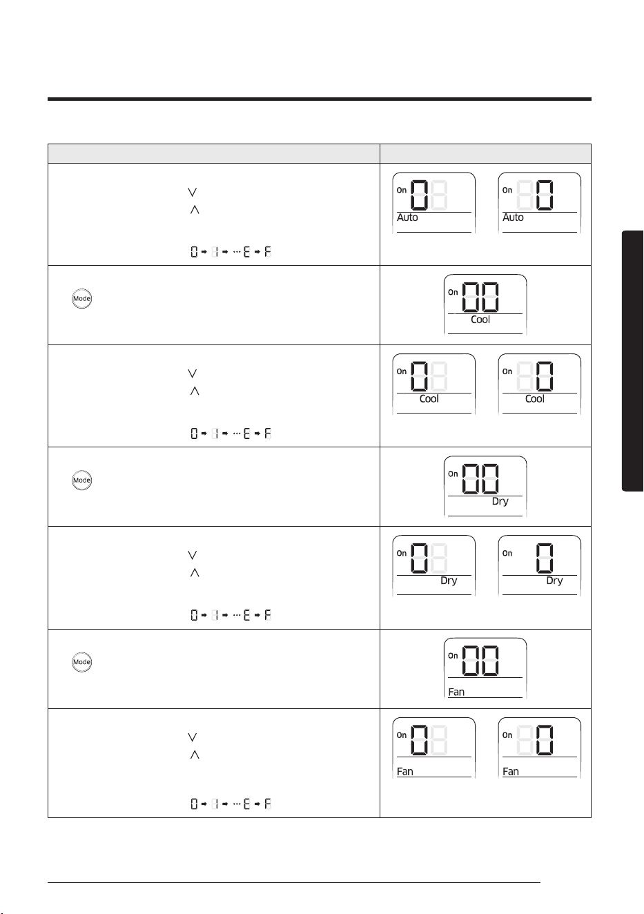
Option setting Status
1 Setting SEG2, SEG3 option
a Press Low Fan button(
) to enter SEG2 value.
b Press High Fan button(
) to enter SEG3 value.
Each time you press the button, will be selected in rotation.
SEG2 SEG3
2 Setting Cool mode
Press Mode button to be changed to Cool mode in the ON status.
3 Setting SEG4, SEG5 option
a Press Low Fan button(
) to enter SEG4 value.
b Press High Fan button(
) to enter SEG5 value.
Each time you press the button, will be selected in rotation.
SEG4 SEG5
4 Setting Dry mode
Press Mode button to be changed to DRY mode in the ON status.
5 Setting SEG6, SEG8 option
a Press Low Fan button(
) to enter SEG6 value.
b Press High Fan button(
) to enter SEG8 value.
Each time you press the button, will be selected in rotation.
SEG6 SEG8
6 Setting Fan mode
Press Mode button to be changed to FAN mode in the ON status.
7 Setting SEG9, SEG10 option
a Press Low Fan button(
) to enter SEG9 value.
b Press High Fan button(
) to enter SEG10 value.
Each time you press the button, will be selected in rotation.
SEG9 SEG10
40 English
Installation part
Installation Procedure
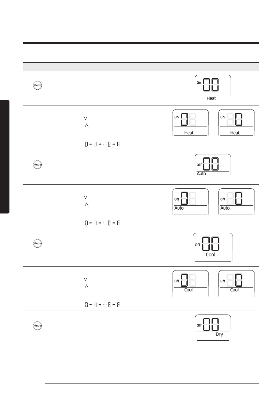
Option setting Status
8 Setting Heat mode
Press Mode button to be changed to HEAT mode in the ON status.
9 Setting SEG11, SEG12 option
a Press Low Fan button(
) to enter SEG11 value.
b Press High Fan button(
) to enter SEG12 value.
Each time you press the button, will be selected in rotation.
SEG11 SEG12
10 Setting Auto mode
Press Mode button to be changed to AUTO mode in the OFF status.
11 Setting SEG14, SEG15 option
a Press Low Fan button(
) to enter SEG14 value.
b Press High Fan button(
) to enter SEG15 value.
Each time you press the button, will be selected in rotation.
SEG14 SEG15
12 Setting Cool mode
Press Mode button to be change to Cool mode in the OFF status.
13 Setting SEG16, SEG17 option
a Press Low Fan button(
) to enter SEG16 value.
b Press High Fan button(
) to enter SEG17 value.
Each time you press the button, will be selected in rotation.
SEG16 SEG17
14 Setting Dry mode
Press Mode button to be change to Dry mode in the OFF status.
41English
Installation part
Option setting Status
15 Setting SEG18, SEG20 option
a Press Low Fan button(
) to enter SEG18 value.
b Press High Fan button(
) to enter SEG20 value.
Each time you press the button, will be selected in rotation.
SEG18 SEG20
16 Setting Fan mode
Press Mode button to be change to Fan mode in the OFF status.
17 Setting SEG21, SEG22 option
a Press Low Fan button(
) to enter SEG21 value.
b Press High Fan button(
) to enter SEG22 value.
Each time you press the button, will be selected in rotation.
SEG21 SEG22
18 Setting Heat mode
Press Mode button to be change to HEAT mode in the OFF status.
19 Setting SEG23, SEG24 mode
a Press Low Fan button(
) to enter SEG23 value.
b Press High Fan button(
) to enter SEG24 value.
Each time you press the button, will be selected in rotation.
SEG23 SEG24
5 After setting option, press button to check whether the option code you input is correct or not.
6 Press operation button with the direction of remote control for set. For the correct option setting, you must input
the option twice.
7 Check operation.
a Reset the indoor unit by pressing the RESET button of indoor unit or outdoor unit.
b Take the batteries out of the remote control and insert them again and then press the operation button.
42 English
Installation part
Setting an indoor unit address (MAIN/RMC/MCU port)
1 Check whether power is supplied or not.
– When the indoor unit is not plugged in, there should be additional power supply in the indoor unit.
2 Before installing the indoor unit, assign an address to the indoor unit according to the air conditioning system plan.
3 Assign an indoor unit address by wireless remote controller.
The initial setting status of indoor unit ADDRESS(MAIN/RMC/MCU port) is “0A0000-100000-200000-300000”.
NOTE
Also set the MCU and Indoor units address by using Add-on > Change address on S-NET Pro 2.
(For more information, see the S-NET Pro 2 Help.)
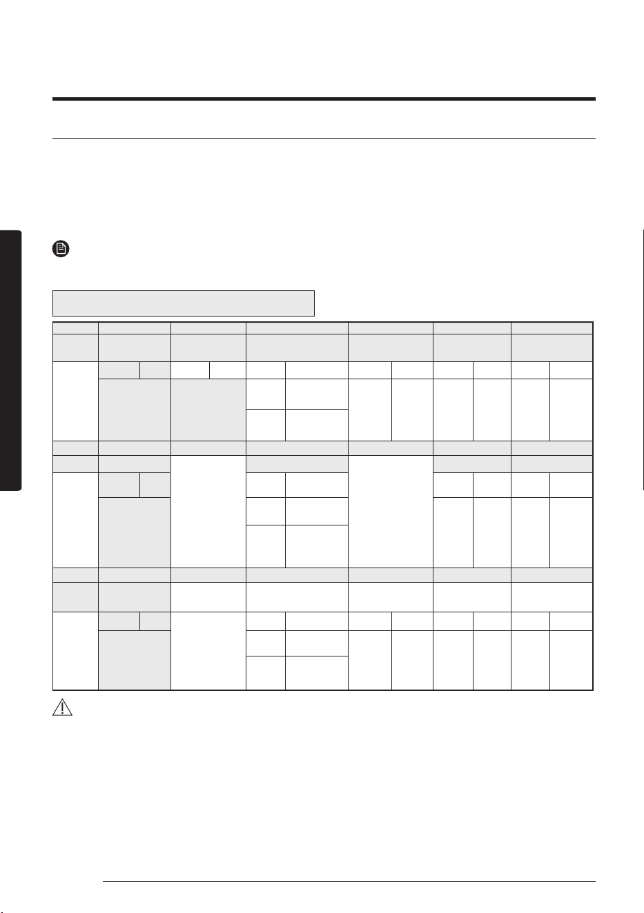
Option No. : 0AXXXX-1XXXXX-2XXXXX-3XXXXX
Option SEG1 SEG2 SEG3 SEG4 SEG5 SEG6
Explanation PAGE MODE Setting Main address
100-digit of indoor unit
address
10-digit of indoor unit
The unit digit of an
indoor unit
Indication
and Details
Indication Details Indication Details Indication Details Indication Details Indication Details Indication Details
0 A
0 No Main address
0~9 100-digit 0~9 10-digit 0~9 A unit digit
1
Main address
setting mode
Option SEG7 SEG8 SEG9 SEG10 SEG11 SEG12
Explanation PAGE
-
Setting RMC address
-
Group channel(*16) Group address
Indication
and Details
Indication Details Indication Details Indication Details Indication Details
1
0 No RMC address
RMC1 0~F RMC2 0~F
1
RMC address
setting mode
Option SEG13 SEG14 SEG15 SEG16 SEG17 SEG18
Explanation PAGE
-
Setting MCU PORT address
10-digit of MCU address
1-digit of MCU MCU PORT address
Indication
and Details
Indication Details
-
Indication Details Indication Details Indication Details Indication Details
2
0
No MCU PORT
0~1 10-digit 0~9 1-digit A~F
PORT
Location
1
MCU PORT
address setting
mode
CAUTION
• When A~F is entered to SEG5~6, the indoor unit MAIN ADDRESS is not changed.
• If you set the SEG 3 as 0, the indoor unit will maintain the previous MAIN ADDRESS even if you input the option
value of SEG5~6.
• If you set the SEG 9 as 0, the indoor unit will maintain previous RMC ADDRESS even if you input the option value of
SEG11~12.
• You cannot set SEG11 and SEG12 as F value at the same time.
• If the indoor unit is connected to the MCU, you can set the SEG 15~18.
Ex.) If you want to set the indoor unit to ‘A’ port of MCU #1. (0A0000 – 100000 – 20101A -30000)
43English
Installation part
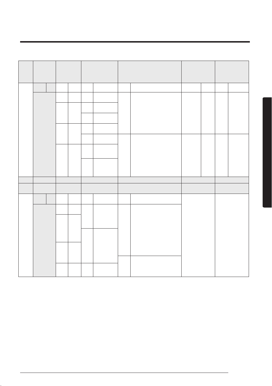
Setting an indoor unit installation option (suitable for the condition of each installation location)
1 Check whether power is supplied or not.
– When the indoor unit is not plugged in, there should be additional power supply in the indoor unit.
2 Set the installation option according to the installation condition of an air conditioner.
– The default setting of an indoor unit installation option is 020010-100000- 200000-300000.
– Individual control of a remote control(SEG20) is the function that controls an indoor unit individually when there
is more than one indoor unit.
3 Set the indoor unit option by wireless remote control.
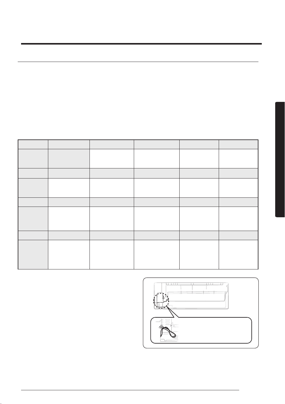
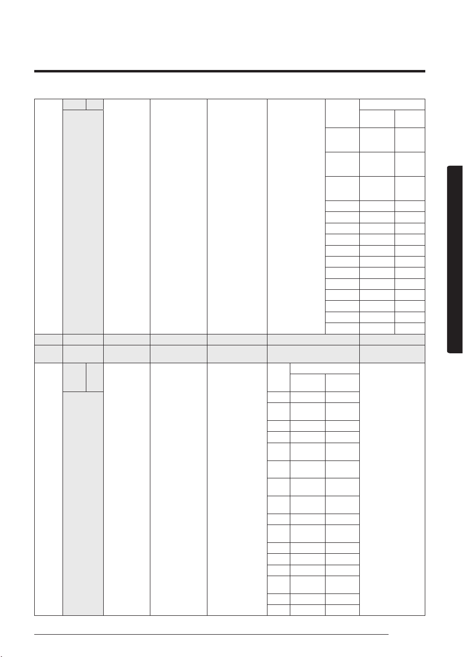
02 series installation option
SEG1 SEG2 SEG3 SEG4 SEG5 SEG6
0 2 Evaporator Drying
Use of external room
temperature sensor /
Minimizing fan operation
when thermostat is off
Use of central control FAN RPM compensation
SEG7 SEG8 SEG9 SEG10 SEG11 SEG12
1 - Use of hot water heater -
EEV Step when
heating stops
-
SEG13 SEG14 SEG15 SEG16 SEG17 SEG18
2 Use of external control
Setting the output of
external control / External
heater signal / Cooling
operation signal / Free
Cooling control signal
S-Plasma ion Buzzer control Hours of lter usage
SEG19 SEG20 SEG21 SEG22 SEG23 SEG24
3
Individual control of a
remote controller
Heating setting
compensation
Adjusted EEV step of stopped
unit during oil return /defrost
mode.
- -
• When setting the option other than above SEG values,
the option will be set as “0”.
• SEG5 central control option is basically set as 1 (Use),
so you don’t need to set the central control option
additionally.
However, if the central control is not connected but
it doesn’t indicate an error message, you need to set
the central control option as 0 (Disuse) to exclude the
indoor unit from the central control.
• The external output of SEG15 is generated by
MIM-B14 connection. (Refer to the manual of
MIM-B14.)
You can connect MIM-B14 to
two female wires at the back
side of the indoor unit.
44 English
Installation part
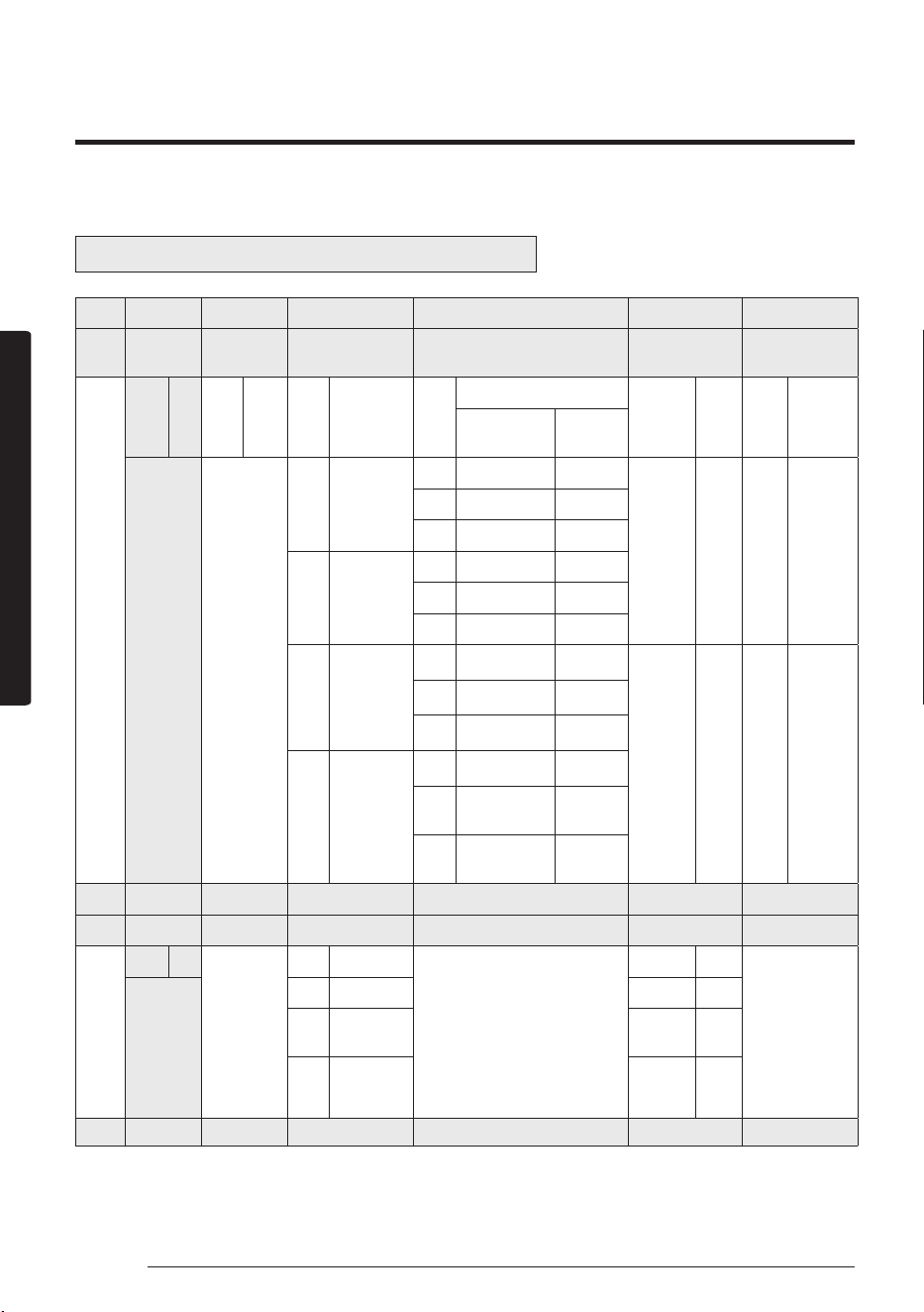
02 series installation option(Detailed)
Option No. : 02XXXX-1XXXXX-2XXXXX-3XXXXX
Option SEG1 SEG2 SEG3 SEG4 SEG5 SEG6
Explanation PAGE MODE Evaporator Drying
Use of external room temperature
sensor / Minimizing fan operation when
thermostat is off
Use of central control FAN RPM compensation
Indication
and Details
Indication
Details Indication Details Indication Details Indication
Details
Indication Details Indication Details
Use of External room
temperature sensor
Minimizing fan
operation when
thermostat is off
0
2
0 Disuse
0 Default Default
0 Disuse 0 Disuse
1 Use Disuse
2 Disuse Use (Heating) (*2)
2 Use (5min) (*1)
3 Use Use (Heating) (*2)
4 Disuse Use (Cooling) (*2)
5 Use Use (Cooling) (*2)
4 Use (10min) (*1)
6 Disuse
Use (Heating /
Cooling) (*2)
1 Use 1
RPM
compensation
7 Use
Use (Heating /
Cooling) (*2)
8 Disuse
Use (Cooling Ultra
Low Fan ) (*2)
6 Use (30min) (*1)
9 Use
Use (Cooling Ultra
Low Fan ) (*2)
A Disuse
Use (Heating /
Cooling Ultra Low
Fan ) (*2)
B Use
Use (Heating /
Cooling Ultra Low
Fan ) (*2)
Option
SEG7
SEG8 SEG9 SEG10 SEG11 SEG12
Explanation
PAGE
- Use of hot water heater - EEV Step when heating stops -
Indication
and Details
Indication
Details
-
Indication Details
-
Indication Details
-
1
0 Disuse 0 Default
1 Use (*3) 1
Adjusted
EEV Step
setting
3 Use (*3) 2~B
Opening
EEV Step
setting
(*4)
Option
SEG13
SEG14 SEG15 SEG16 SEG17 SEG18
45English
Installation part
Explanation
PAGE
Use of external control
Setting the output of external
control
/ External heater signal / Cooling
operation signal / Free Cooling
control signal
S-Plasma ion Buzzer control Hours of filter usage
Indication
and Details
Indication Details Indication Details Indication Details Indication Details Indication Details Indication Details
2
0 Disuse 0
External control
(Thermo On)
0 Disuse 0 Use buzzer 2 1000 Hour1
ON/OFF
control
1
External control
(Operation On)
2
External heater
signal (*5)
2
OFF
control
3
External heater
signal (*5)
4
Cooling operation
signal (*6)
1 Use 1
Disuse
buzzer
6 2000 Hour
3
Window
ON/OFF
control
5
Free Cooling control
(Cooling Thermo
On) (*7)
6
Free Cooling control
(Cooling/Dry Thermo
On) (*7)
Option SEG19 SEG20 SEG21 SEG22 SEG23 SEG24
Explanation PAGE
Individual control of a
remote controller
Heating setting compensation
Adjusted EEV step of stopped unit during oil return /
defrost mode.
Indication
and Details
Indication Details Indication Details Indication Details Indication Details
- -
3
0 or 1 channel 1
0 Default
0 Default
2 channel 2
1 2 °C
3 channel 3
1 Adjusted EEV positon
4 channel 4 2 5 °C
(*1) When Cooling or dry mode is off. The indoor fan operate in setting minutes.
(*2) Minimizing fan operation when thermostat is off
– Fan operates for 20 seconds at an interval of 5 minutes in heat mode.
– Fan stops or operates Ultra low in Coolong when thermostat is off.
(*3) 1: Fan is turned on continually when the hot water heater is turned on,
3: Fan is turned off when the hot water heater is turned on with cooling only indoor unit
Cooling only indoor unit: To use this option,install the Mode Select switch(MCM-C200) on the outdoor unit and fix it as
cool mode.
(*4) It is only for wall-mounted indoor unit with EEV Integrated. If any design condition meets either of the following
below, please set SEG11 to “7”.
a The total number of wall-mounted indoor units with EEV Integrated in one (modular) system is more than 20.
46 English
Installation part
b The total number of wall-mounted indoor units with EEV Integrated in one (modular) system is more than “the
total of one(modular) system’s capacity(kW) / 2” (“the total of one(modular) system’s capacity(BTU/h) / 6800”).
ex) Outdoor capacity 28kW
→
28 /2 = 14. The total number of wall-mounted indoor units with EEV Integrated
in one (modular) system is more than 14.Please refer to the EEV step table below for the system (for heating) at
stop.
Indication 0 2 3 4 5 6 7 8 9 A B
Stopped
Unit's EEV step
Default
90
↔
160 100
↔
160 110
↔
160 120
↔
160 130
↔
160
160 200 250 300 400
(*5) When the following 2 or 3 is used as external heater On/Off signal, the signal for monitoring external contact control
will not be output.
2: Fan is turned on continually when the external heater is turned on,
3: Fan is turned off when the external heater is turned on with cooling only indoor unit
Cooling only indoor unit: To use this option,install the Mode Select switch(MCM-C200) on the outdoor unit and fix it as
cool mod.·
• If Fan is set to off for cooling only indoor unit by setting the SEG9=3 or SEG15=3, you need to use an external
sensor or wired remote controller sensor to detect indoor temperature exactly.
(*6) When indoor unit is in cooling or Dry mode, The output signal is "ON".
(*7) For free cooling control, Economizer controller is required.
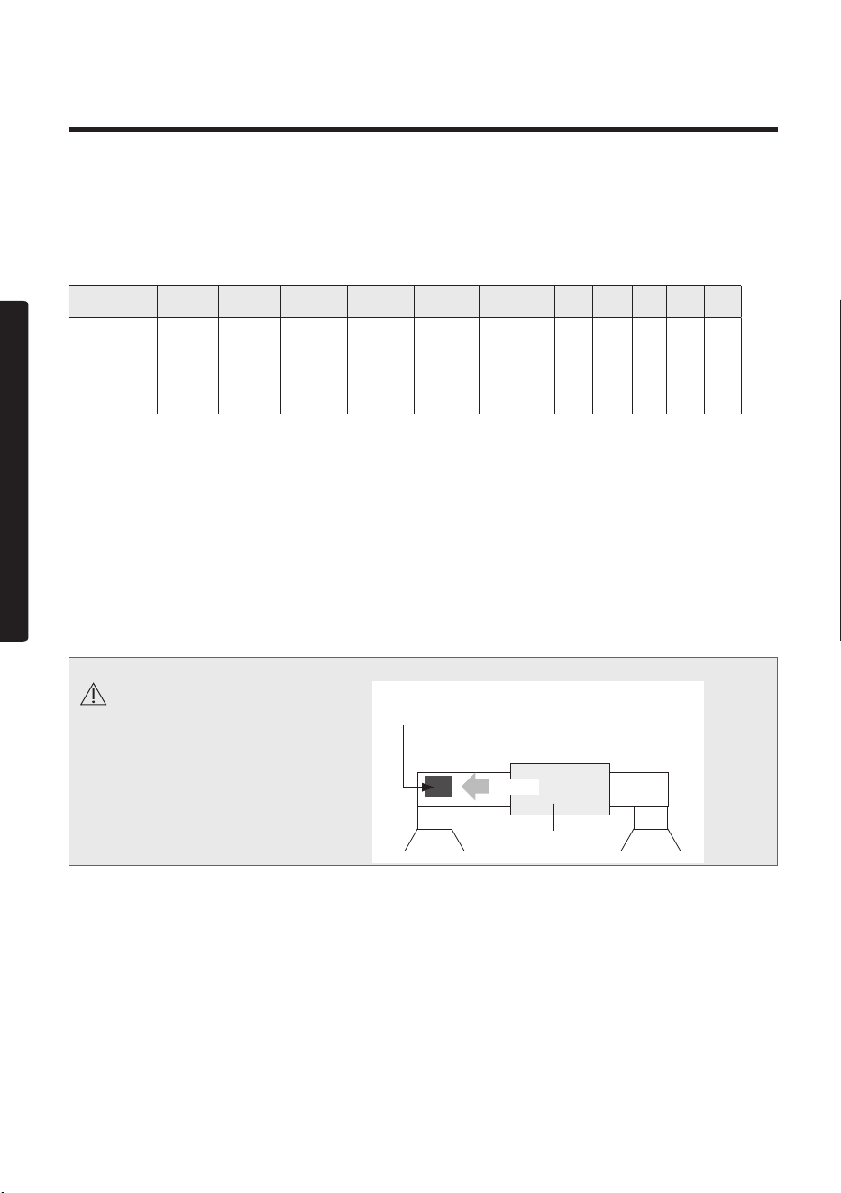
CAUTION
Do not install the electronic heater
in the flow channel of the indoor
unit fan.
Air Flow
Suction side Discharge side
Electronic heater should
not be installed.
Duct Indoor unit
47English
Installation part
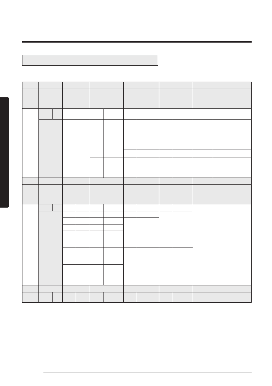
05 series installation option
SEG1 SEG2 SEG3 SEG4 SEG5 SEG6
0 5
Use of Auto Change Over or
cooling only for HR only
(When setting SEG3)
Standard heating temp.
Offset
(When setting SEG3)
Standard cooling temp.
Offset
(When setting SEG3)
Standard for mode change
Heating
→
Cooling
SEG7 SEG8 SEG9 SEG10 SEG11 SEG12
1
(When setting SEG3) Standard
for mode change Cooling
→Heating
(When setting SEG3) Time
required for mode change
Compensation option
for Long pipe or height
difference between indoor
units
MTFC (*3) -
SEG13 SEG14 SEG15 SEG16 SEG17 SEG18
2 - - - -
Control variables when
using hot water / external
heater (*4)
SEG19 SEG20 SEG21 SEG22 SEG23 SEG24
3 - - -
Forced FAN Operation
for Heating and Cooling
-
48 English
Installation part
Option SEG1 SEG2 SEG3 SEG4
SEG5
SEG6
Explanation PAGE MODE
Use of Auto Change Over or
Cooling only for HR only
(When setting SEG3)
Standard heating
temp. Offset
(When setting SEG3)
Standard cooling temp.
Offset
(When setting SEG3)
Standard for mode
change
Heating
→
Cooling
Indication
and Details
Indication Details Indication Details Indication Details Indication Details
Indication
Details
Indication Details
0 5
0
Follow
product option
0 0
°C
0
0
°C
0 1
°C
1 0.5
°C
1
0.5
°C
1 1.5
°C
1
Use Auto
Change
Over for
HR only
2 1
°C
2
1
°C
2 2
°C
3 1.5
°C
3
1.5
°C
3 2.5
°C
4 2
°C
4
2
°C
4 3
°C
2
Use Cooling
only indoor unit
for HR
5 2.5
°C
5
2.5
°C
5 3.5
°C
6 3
°C
6
3
°C
6 4
°C
7 3.5
°C
7
3.5
°C
7 4.5
°C
Option SEG7 SEG8 SEG9 SEG10
SEG11
SEG12
Explanation PAGE
(When setting SEG3)
Standard for mode
changing Cooling
→
Heating mode
(When setting SEG3)
Time required for
mode change
Compensation option
for Long pipe or height
diffference between
indoor units
MTFC (*3)
Indication
and Details
Indication Details Indication Details Indication Details Indication Details
Indication Details
-
1
0 1
°C
0 5min 0 Default
0 Default
1 1.5
°C
1 7min
1
(*1) Height
difference
is more than
30m or
(*2) Distance
is longer than
110m
2 2
°C
2 9min
3 2.5
°C
3 11min
4 3
°C
4 13min
2
(*1) Height
difference is
15~30m or
(*2) Distance is
50~110m
2 Use
5 3.5
°C
5 15min
6 4
°C
6 20min
7 4.5
°C
7 30min
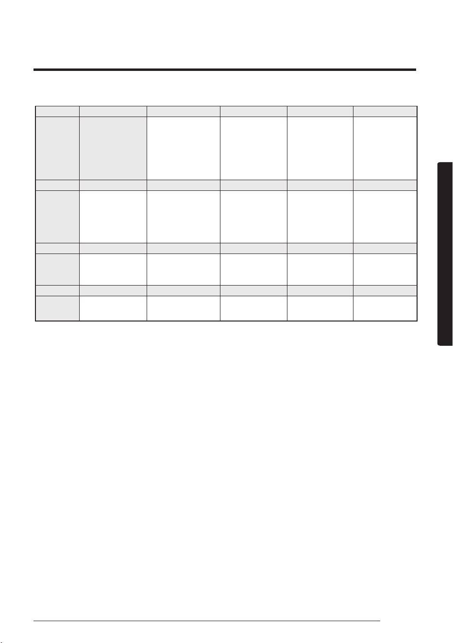
Option SEG13 SEG14 SEG15 SEG16 SEG17 SEG18
Explanation - - - - - - - - - -
Control variables when using hot water / external
heater (*4)
05 series installation option(Detailed)
Option No. : 0XXXX-1XXXXX-2XXXXX-3XXXXX
49English
Installation part
Indication
and Details
Indication Details
- - - -
Indication
Details
2
Set temp. for
heater On/Off
Delay time for
heater On
0
At the same
time as
thermo on
No delay
1
At the same
time as
thermo on
10 minutes
2
At the same
time as
thermo on
20 minutes
3 1.5 °C No delay
4 1.5 °C 10 minutes
5 1.5 °C 20 minutes
6 3.0 °C No delay
7 3.0 °C 10 minutes
8 3.0 °C 20 minutes
9 4.5 °C No delay
A 4.5 °C 10 minutes
B 4.5 °C 20 minutes
C 6.0 °C No delay
D 6.0 °C 10 minutes
E 6.0 °C 20 minutes
Option SEG19 SEG20 SEG21 SEG22 SEG23 SEG24
Explanation PAGE - - -
Forcing FAN Operation for Heating and
Cooling
-
Indication
and Details
Indication Details
- - -
Indication
Details
-
Cooling Fan
Setting
Heating Fan
Setting
3
0 Disuse Disuse
1 Disuse
Use (Fan: User
setting)
2 Disuse Use (Fan: High)
3 Disuse Use (Fan: Low)
4
Use (Fan: User
setting)
Disuse
5
Use (Fan: User
setting)
Use (Fan: User
setting)
6
Use (Fan: User
setting)
Use (Fan: High)
7
Use (Fan: User
setting)
Use (Fan: Low)
8 Use (Fan: High) Disuse
9 Use (Fan: High)
Use (Fan: User
setting)
A Use (Fan: High) Use (Fan: High)
B Use (Fan: High) Use (Fan: Low)
C Use (Fan: Low) Disuse
D Use (Fan: Low)
Use (Fan: User
setting)
E Use (Fan: Low) Use (Fan: High)
F Use (Fan: Low) Use (Fan: Low)
50 English
Installation part
(*1) Height difference : The difference of the height between the corresponding indoor uint and the indoor unit installed
at the lowest place. For example, When the indoor unit is installed 40m higher than the indoor unit
installed at the lowest place, select the option "1".
(*2) Distance : The difference between the pipe length of the indoor unit istalled at farthest place from an outdoor unit
and the pipe length of the corresponding indoor unit from an outdoor unit. For example, when the farthest
pipe length is 100 m(328 ft) and the corresponding indoor unit is 40 m away from an outdoor unit, select
the option "2". (100 - 40 = 60m)
(*3) For MTFC option, MTFC(Multi Tenant Function Controller) kit is required.
(*4) Heater operation when the SEG9 of 02 series installation option is set to using hot water heater or when SEG15 is set
to using external heater
e.g. 1) Setting 02 series SEG9 =”1” / Setting 05 series SEG18 = “0”: Hot water heater is turned on at the same time as
the heating thermostat is on, and turned off when the heating thermostat is off.
e.g. 2) Setting 02 series SEG15 =”2” / Setting 05 series SEG18 =”A”:Room temp. ≤ set temp. + f(heating compensation
temp.)
• External heater is turned on when the temperature is maintained as 4.5 °C for 10 minutes. Room temp. > set
temp. + f(heating compensation temp.)
• External heater is turned off when the temperature is maintained as 4.5 °C + 1 °C (1 °C is the Hysteresis for
On/Off selection.)
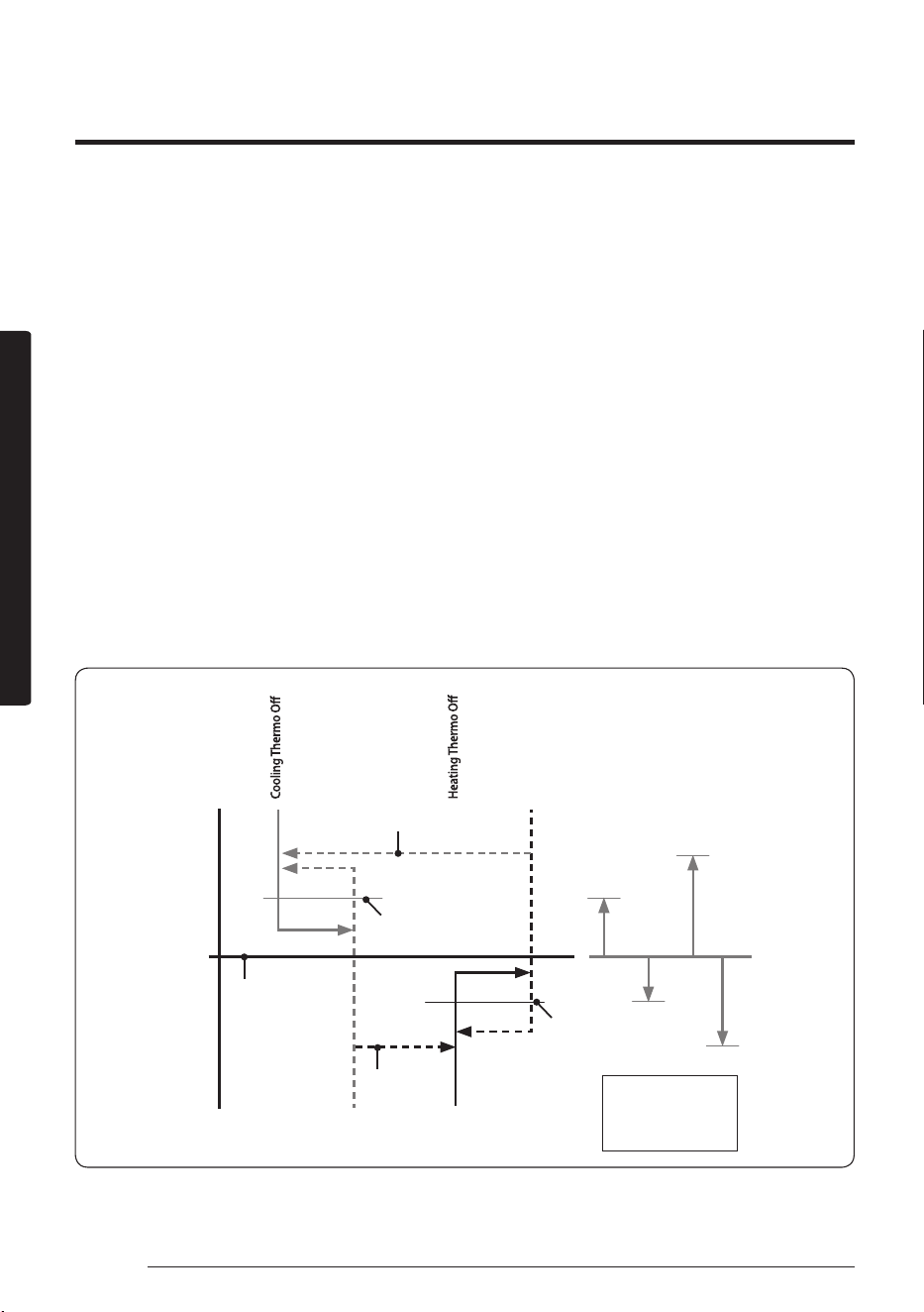
SEG 3, 4, 5, 6, 8, 9 additional information
When the SEG 3 is set as "1" and follow Auto Change Over for HR only operation, it will operate as follows.
A : Set with SEG4(˚C)
B : Set with SEG5(˚C)
C : Set with SEG6(˚C)
D : Set with SEG8(˚C)
Cooling Thermo On
Heating Thermo On
B C
D
Ts
A
c
a
Temp.
d
b
Standard temp.
for Heating
Standard temp.
for Cooling
Standard temp. for
Heating → Cooling
Standard temp.
for
Heating → Cooling
Set temp.
for Auto mode
Cooling/Heating mode can be changed when Thermo Off status is maintained during the time with SEG9.
51English
Installation part
Installation Procedure
Changing a particular option
You can change each digit of set option.
Option SEG1 SEG2 SEG3 SEG4 SEG5 SEG6
Explanation PAGE MODE
The option mode
you want to change
The tens’ digit of an
option SEG you will
change
The unit digit of an
option SEG you will
change
Changed value
Indication
and Details
Indication DetailsI Indication Details Indication Details Indication Details Indication Details Indication Details
0 D
Option
mode
1~6
Tens’
digit of
SEG
0~9
Unit digit
of SEG
0~9
The
changed
value
0~F
NOTE
• When changing a digit of an indoor unit address setting option, set the SEG3 as ‘A’.
• When changing a digit of indoor unit installation option, set the SEG3 as ‘2’.
Ex) When setting the ‘buzzer control’ into disuse status.
Option SEG1 SEG2 SEG3 SEG4 SEG5 SEG6
Explanation PAGE MODE
The option mode
you want to change
The tens’ digit of an
option SEG you will
change
The unit digit of an
option SEG you will
change
Changed value
Indication 0 D 2 1 7 1
CAUTION
• If you are using heat pump model, mixed operation mode (two or more indoor units operating in different operation
mode simultaneously) is not available when the indoor units are connected to same outdoor unit. If you set the
master indoor unit with a remote control, outdoor unit will operate in the mode which was set in the master indoor
unit.