Loading ...
Loading ...
Loading ...
10
11
INSTALLING THE CHAINS
The chains shipped with the range must be properly secured to the
rear wall. The height of the bracket from the floor must be determined
after the range legs have been adjusted to the desired height and after
the range has been leveled. If the chain length is too short to properly
secure the range to the rear wall, ask the installer to lengthen it.
• Reinstall the chains every time that the range is relocated.
• Do not operate the range without the chains in place and engaged.
1110
INSTALLING THE CHAINS
The chains shipped with the range must be properly secured to the
rear wall. The height of the bracket from the floor must be determined
after the range legs have been adjusted to the desired height and after
the range has been leveled. If the chain length is too short to properly
secure the range to the rear wall, ask the installer to lengthen it.
• Reinstall the chains every time that the range is relocated.
• Do not operate the range without the chains in place and engaged.
!&*+$$!&+ &+!+!(*E23:=:EJ-!
+962?E:E:A3C24<6ED9:AA65H:E9E96C2?86>FDE36AC@A6C=JD64FC65
E@E96C62CH2==2DD9@H?:?E96A:4EFC636=@H+9696:89E@7E963C24<6E
7C@>E967=@@C>FDE3656E6C>:?6527E6CE96C2?86=68D92G6366?
25;FDE65E@E9656D:C6596:89E2?527E6CE96C2?8692D366?=6G6==65
%62DFC6E965:DE2?467C@>E967=@@CE@E963@EE@>@7E962?E:E:A
3C24<6EC646AE24=6@?E96324<@7E962AA=:2?46
(@D:E:@?E96EH@2?E:E:A3C24<6ED@?E96H2==2EE9656D:C6596:89E
A=FDQ4>+963C24<6ED>FDE36A=24652EQ4>
7C@>E96D:56@7E96C2?86+965:DE2?4636EH66?E96EH@3C24<6E
:DQ=4>*64FC6E963C24<6EDE@E96H2==H:E92AAC@AC:2E6
92C5H2C6*=:56E96C2?86282:?DEE96H2==F?E:=E963C24<6ED2C67F==J
:?D6CE65:?E@E96:CC646AE24=6D@?E96324<@7E96C2?86964<E@D66
E92EE96?E:+:A56G:46:D:?DE2==65AC@A6C=J+96?8C2DAE96E@AC62C
6586@7E96C2?862?542C67F==J2EE6>AEE@E:=E:E7@CH2C5-6C:7JE92EE96
?E:+:A56G:46:D6?82865
'CFD6E962?E:E:A56G:462D@?6492:?2?5E:89E6?FAH:E97:I65
D4C6H@?E96H2==2?5H96?E96H2==?@EDF:E23=67@C:?DE2==2E:@?E96
492:?D92==367:I65E@E96423:?6EDECF4EFC6
INSTALL
GUIDE
a)" A child or adult can tip the range and be killed."
b)" Install the anti-tip device to the structure and/or the range".
c)" Engage the range to the anti-tip device."
d)" Re-engage the anti-tip device if the range is moved."
e)" See installation instructions for details."
f)" Failure to do so can result in death or serious burns to children or adults."
WARNING
MASTER CONTRACT: 272713
REPORT: 80028905
PROJECT: 80028905
Att3 Instructions Page 17
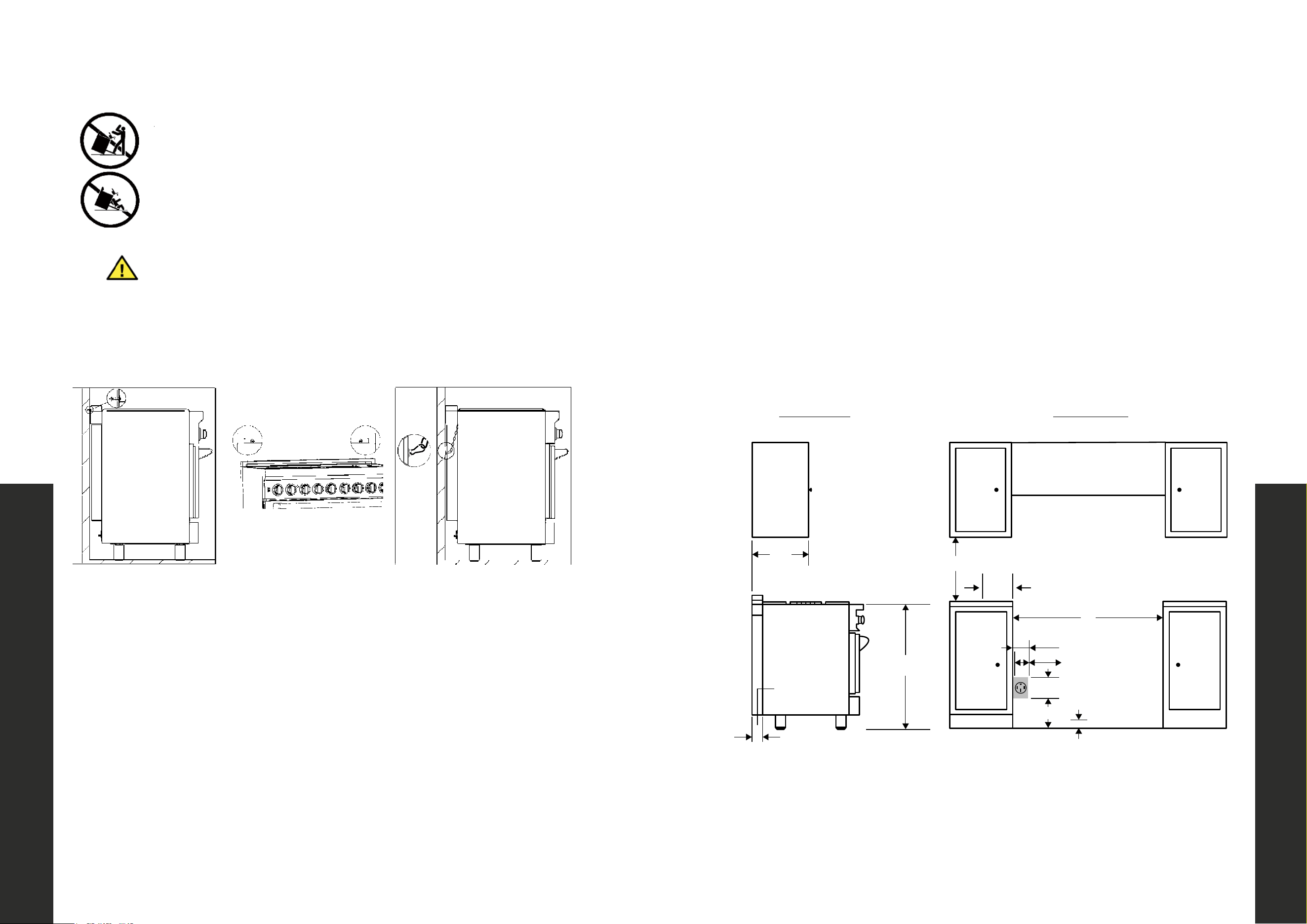
Measure the distance from the floor to the where the chains connect on the back of
the appliance.
1. Position the ends of the chains on the wall at the desired height plus 1/8”. The
chains must be placed at 2 5/16” from the side of the range. The distance
between the two chains is 25 1/4 “.
2. Secure the ends of the chains to the wall with appropriate hardware.
3. Slide the range against the wall.
4. Check to see that the chains are connected properly. Then grasp the top rear
edge of the range and carefully attempt to tilt it forward. Verify that the chains
are engaged.
5. Or tighten the chains up with fixed screws on the wall. If the wall is not suitable
for installation, then the chains should be fixed to the cabinet structure.
A child or adult can tip the range and be fatally injured; Adjust the
chains if the range is moved. Failure to do so can result in death or
serious injury.
WARNING
INSTALLATION
INSTALLATION ADJACENT TO KITCHEN CABINETS
• The range may be installed directly adjacent to existing countertop height cabinets
(36”) from the floor.
• For the best look, the worktop should be level with the cabinet countertop. This can
be accomplished by raising the unit using the adjustment spindles on the legs.
• ATTENTION: The range CANNOT be installed directly adjacent to kitchen walls, tall
cabinets, tall appliances, or other vertical surfaces above 36˝ high. The minimum
side clearance in such cases is 6”.
• Wall cabinets with minimum side clearance must be installed 18˝ above the
countertop with countertop height between 35 1/2” and 37 1/2”. The maximum
depth of wall cabinets above the range shall be 13”.
INSTALLATION
Cooking Range
13 ”
location of
electrical
extends on floor
30” to 36”
to bottom of
ventilation hood
W
opening width
18 ”
6”
Front View
Side View
3.23”
3.23”
5 ³/₄”
9 ³/₄”
2”
2 ³/
5
”
36 ³/
5
”
EXTERNAL DIMENSIONS:
24” Model: 24”W x 27.4”D x 36”H
30” Model: 30”W x 27.4”D x 36”H
36” Model: 36”W x 27.4”D x 36”H
INTERNAL DIMENSIONS
24” Model: 18.5”W x 18.5” D x 14”H
30” Model: 26.5”W x 18.5”D x 14”H
36” Model: 30.5”W x 18.5”D x 14”H
Installing the Chains
Installation Requirements
IMPORTANT SAFETY INSTRUCTIONS
==C2?86D42?E:A
!?;FCJE@A6CD@?D4@F=5C6DF=E
!?DE2==2?E:E:A56G:46DA24<65
H:E9C2?86
*66:?DE2==2E:@?:?DECF4E:@?D
W
ARNING
+9:DC2?86>FDE36D64FC652?54@??64E65FD:?8E962?E:E:A
56G:46244@C5:?8E@E96:?DE2==2E:@?:?DECF4E:@?D
!7J@F92G6>@G65E96C2?86D=:56E96=@4<:?8=2E49@?E@E96
2?E:E:A56G:46F?E:=J@F766=:E=@4<:?E@A=246
@?@EFD6E96C2?86:7E962?E:E:A56G:4692D?@E366?AC@A6C=J
:?DE2==652?56?82865
2:=FC6E@@3D6CG6E96:?7@C>2E:@?4@?E2:?65:?E96:?DE2==2E:@?
:?DECF4E:@?D42?=625E@D6C:@FD@C72E2=:?;FC:6D7@C49:=5C6?2?5
25F=ED
WARNING
A child or adult can tip the range and be killed.
Re-engage the anti-tip device if fhe range is moved.Do not operate
the range without the anti-tip device in place and engaged.
See installation instructions for details
Failure to do so can result in death or serious burns to children or
!?DE2==2?E:E:A56G:46DA24<65
adults.
MASTER CONTRACT: 272713
REPORT: 80028905
PROJECT: 80028905
Att3 Instructions Page 3
Measure the distance from the floor to the where the chains connect on the back of
the appliance.
1. Position the ends of the chains on the wall at the desired height plus 1/8”. The
chains must be placed at 2 5/16” from the side of the range. The distance
between the two chains is 25 1/4 “.
2. Secure the ends of the chains to the wall with appropriate hardware.
3. Slide the range against the wall.
4. Check to see that the chains are connected properly. Then grasp the top rear
edge of the range and carefully attempt to tilt it forward. Verify that the chains
are engaged.
5. Or tighten the chains up with fixed screws on the wall. If the wall is not suitable
for installation, then the chains should be fixed to the cabinet structure.
A child or adult can tip the range and be fatally injured; Adjust the
chains if the range is moved. Failure to do so can result in death or
serious injury.
WARNING
INSTALLATION
INSTALLATION ADJACENT TO KITCHEN CABINETS
• The range may be installed directly adjacent to existing countertop height cabinets
(36”) from the floor.
• For the best look, the worktop should be level with the cabinet countertop. This can
be accomplished by raising the unit using the adjustment spindles on the legs.
• ATTENTION: The range CANNOT be installed directly adjacent to kitchen walls, tall
cabinets, tall appliances, or other vertical surfaces above 36˝ high. The minimum
side clearance in such cases is 6”.
• Wall cabinets with minimum side clearance must be installed 18˝ above the
countertop with countertop height between 35 1/2” and 37 1/2”. The maximum
depth of wall cabinets above the range shall be 13”.
INSTALLATION
Cooking Range
13 ”
location of
electrical
extends on floor
W
opening width
18 ”
6”
Front View
Side View
3.23”
3.23”
5 ³/₄”
9 ³/₄”
2”
2 ³/
5
”
36 ³/
5
”
EXTERNAL DIMENSIONS:
24” Model: 24”W x 27.4”D x 36”H
30” Model: 30”W x 27.4”D x 36”H
36” Model: 36”W x 27.4”D x 36”H
INTERNAL DIMENSIONS
24” Model: 18.5”W x 18.5” D x 14”H
30” Model: 26.5”W x 18.5”D x 14”H
36” Model: 30.5”W x 18.5”D x 14”H
Installing the Chains
Installation Requirements
IMPORTANT SAFETY INSTRUCTIONS
All ranges can tip
Injury to persons could result
Install anti-tip devices packed
with range
See installation instructions
!
W
ARNING
This range must be secured and connected using the anti-tip
device according to the installation instructions.
If you have moved the range, slide the locking latch onto the
anti- tip device until you feel it lock into place.
Do not use the range if the anti-tip device has not been properly
installed and engaged.
Failure to observe the information contained in the installation
instructions can lead to serious or fatal injuries for children and
adults.
!
WARNING
A child or adult can tip the range and be killed.
Re-engage the anti-tip device if fhe range is moved.Do not operate
the range without the anti-tip device in place and engaged.
See installation instructions for details
Failure to do so can result in death or serious burns to children or
Install anti-tip devices packed
adults.
MASTER CONTRACT: 272713
REPORT: 80028905
PROJECT: 80028905
Att3 Instructions Page 3
Loading ...
Loading ...
Loading ...