
Radar-Assisted Traffic Camera
User Manual

Radar-Assisted Traffic Camera User Manual
i
Legal Information
© 2020 Hangzhou Hikvision Digital Technology Co., Ltd. All rights reserved.
About this Manual
The Manual includes instructions for using and managing the Product. Pictures, charts, images and
all other information hereinafter are for description and explanation only. The information
contained in the Manual is subject to change, without notice, due to firmware updates or other
reasons. Please find the latest version of this Manual at the Hikvision website
(https://www.hikvision.com/).
Please use this Manual with the guidance and assistance of professionals trained in supporting the
Product.
Trademarks
and other Hikvision's trademarks and logos are the properties of
Hikvision in various jurisdictions.
Other trademarks and logos mentioned are the properties of their respective owners.
Disclaimer
TO THE MAXIMUM EXTENT PERMITTED BY APPLICABLE LAW, THIS MANUAL AND THE PRODUCT
DESCRIBED, WITH ITS HARDWARE, SOFTWARE AND FIRMWARE, ARE PROVIDED “AS IS” AND
“WITH ALL FAULTS AND ERRORS”. HIKVISION MAKES NO WARRANTIES, EXPRESS OR IMPLIED,
INCLUDING WITHOUT LIMITATION, MERCHANTABILITY, SATISFACTORY QUALITY, OR FITNESS FOR
A PARTICULAR PURPOSE. THE USE OF THE PRODUCT BY YOU IS AT YOUR OWN RISK. IN NO EVENT
WILL HIKVISION BE LIABLE TO YOU FOR ANY SPECIAL, CONSEQUENTIAL, INCIDENTAL, OR INDIRECT
DAMAGES, INCLUDING, AMONG OTHERS, DAMAGES FOR LOSS OF BUSINESS PROFITS, BUSINESS
INTERRUPTION, OR LOSS OF DATA, CORRUPTION OF SYSTEMS, OR LOSS OF DOCUMENTATION,
WHETHER BASED ON BREACH OF CONTRACT, TORT (INCLUDING NEGLIGENCE), PRODUCT LIABILITY,
OR OTHERWISE, IN CONNECTION WITH THE USE OF THE PRODUCT, EVEN IF HIKVISION HAS BEEN
ADVISED OF THE POSSIBILITY OF SUCH DAMAGES OR LOSS.
YOU ACKNOWLEDGE THAT THE NATURE OF THE INTERNET PROVIDES FOR INHERENT SECURITY
RISKS, AND HIKVISION SHALL NOT TAKE ANY RESPONSIBILITIES FOR ABNORMAL OPERATION,
PRIVACY LEAKAGE OR OTHER DAMAGES RESULTING FROM CYBER-ATTACK, HACKER ATTACK,
VIRUS INFECTION, OR OTHER INTERNET SECURITY RISKS; HOWEVER, HIKVISION WILL PROVIDE
TIMELY TECHNICAL SUPPORT IF REQUIRED.
YOU AGREE TO USE THIS PRODUCT IN COMPLIANCE WITH ALL APPLICABLE LAWS, AND YOU ARE
SOLELY RESPONSIBLE FOR ENSURING THAT YOUR USE CONFORMS TO THE APPLICABLE LAW.
ESPECIALLY, YOU ARE RESPONSIBLE, FOR USING THIS PRODUCT IN A MANNER THAT DOES NOT
INFRINGE ON THE RIGHTS OF THIRD PARTIES, INCLUDING WITHOUT LIMITATION, RIGHTS OF
PUBLICITY, INTELLECTUAL PROPERTY RIGHTS, OR DATA PROTECTION AND OTHER PRIVACY RIGHTS.
YOU SHALL NOT USE THIS PRODUCT FOR ANY PROHIBITED END-USES, INCLUDING THE
DEVELOPMENT OR PRODUCTION OF WEAPONS OF MASS DESTRUCTION, THE DEVELOPMENT OR

Radar-Assisted Traffic Camera User Manual
ii
PRODUCTION OF CHEMICAL OR BIOLOGICAL WEAPONS, ANY ACTIVITIES IN THE CONTEXT RELATED
TO ANY NUCLEAR EXPLOSIVE OR UNSAFE NUCLEAR FUEL-CYCLE, OR IN SUPPORT OF HUMAN
RIGHTS ABUSES.
IN THE EVENT OF ANY CONFLICTS BETWEEN THIS MANUAL AND THE APPLICABLE LAW, THE LATER
PREVAILS.

Radar-Assisted Traffic Camera User Manual
iii
Regulatory Information
FCC Information
Please take attention that changes or modification not expressly approved by the party
responsible for compliance could void the user's authority to operate the equipment.
FCC compliance: This equipment has been tested and found to comply with the limits for a Class A
digital device, pursuant to part 15 of the FCC Rules. These limits are designed to provide
reasonable protection against harmful interference when the equipment is operated in a
commercial environment. This equipment generates, uses, and can radiate radio frequency energy
and, if not installed and used in accordance with the instruction manual, may cause harmful
interference to radio communications. Operation of this equipment in a residential area is likely to
cause harmful interference in which case the user will be required to correct the interference at
his own expense.
FCC Conditions
This device complies with part 15 of the FCC Rules. Operation is subject to the following two
conditions:
1.
This device may not cause harmful interference.
2.
This device must accept any interference received, including interference that may cause
undesired operation.
EU Conformity Statement
This product and - if applicable - the supplied accessories too are marked with
"CE" and comply therefore with the applicable harmonized European standards
listed under the EMC Directive 2014/30/EU, the LVD Directive 2014/35/EU, the
RoHS Directive 2011/65/EU.
2012/19/EU (WEEE directive): Products marked with this symbol cannot be
disposed of as unsorted municipal waste in the European Union. For proper
recycling, return this product to your local supplier upon the purchase of
equivalent new equipment, or dispose of it at designated collection points. For
more information see: www.recyclethis.info
2006/66/EC (battery directive): This product contains a battery that cannot be
disposed of as unsorted municipal waste in the European Union. See the product
documentation for specific battery information. The battery is marked with this
symbol, which may include lettering to indicate cadmium (Cd), lead (Pb), or
mercury (Hg). For proper recycling, return the battery to your supplier or to a
designated collection point. For more information see: www.recyclethis.info
Industry Canada ICES-003 Compliance
This device meets the CAN ICES-3 (A)/NMB-3(A) standards requirements.
Radar-Assisted Traffic Camera User Manual
iv
Symbol Conventions
The symbols that may be found in this document are defined as follows.
Symbol
Description
Danger
Indicates a hazardous situation which, if not avoided, will or could
result in death or serious injury.
Caution
Indicates a potentially hazardous situation which, if not avoided,
could result in equipment damage, data loss, performance
degradation, or unexpected results.
Note
Provides additional information to emphasize or supplement
important points of the main text.

Radar-Assisted Traffic Camera User Manual
v
Safety Instruction
Regulatory Information
This is a class A product and may cause radio interference in which case the user may be required
to take adequate measures.
Laws and Regulations
Use of the product must be in strict compliance with the local laws and regulations. Please shut
down the device in prohibited area.
Power Supply
●
Use of the product must be in strict compliance with the local electrical safety regulations.
●
Use the power adapter provided by qualified manufacturer. Refer to the product specification
for detailed power requirements.
●
It is recommended to provide independent power adapter for each device as adapter overload
may cause over-heating or a fire hazard.
●
Make sure that the power has been disconnected before you wire, install, or disassemble the
device in the authorized way according to the description in the manual.
●
To avoid electric shock, DO NOT directly touch exposed contacts and components once the
device is powered up.
●
DO NOT use damaged power supply devices (e.g., cable, power adapter, etc.) to avoid electric
shock, fire hazard, and explosion.
●
DO NOT directly cut the power supply to shut down the device. Please shut down the device
normally and then unplug the power cord to avoid data loss.
●
The socket-outlet shall be installed near the equipment and shall be easily accessible.
●
Make sure the power supply has been disconnected if the power adapter is idle.
●
Connect to earth before connecting to the power supply.
Transportation, Use, and Storage
●
To avoid heat accumulation, good ventilation is required for a proper operating environment.
●
Store the device in dry, well-ventilated, corrosive-gas-free, no direct sunlight, and no heating
source environment.
●
Avoid fire, water, and explosive environment when using the device.
●
Install the device in such a way that lightning strikes can be avoided. Provide a surge suppressor
at the inlet opening of the equipment under special conditions such as the mountain top, iron
tower, and forest.
●
Keep the device away from magnetic interference.
●
Avoid device installation on vibratory surfaces or places. Failure to comply with this may cause
device damage.
●
DO NOT touch the heat dissipation component to avoid burns.
●
DO NOT expose the device to extremely hot, cold, or humidity environments. For temperature
and humidity requirements, see device specification.

Radar-Assisted Traffic Camera User Manual
vi
●
No naked flame sources, such as lighted candles, should be placed on the equipment.
●
DO NOT touch the sharp edges or corners.
●
To prevent possible hearing damage, DO NOT listen at high volume levels for long periods.
Maintenance
●
If smoke, odor, or noise arises from the device, immediately turn off the power, unplug the
power cable, and contact the service center.
●
If the device cannot work properly, contact the store you purchased it or the nearest service
center. DO NOT disassemble or modify the device in the unauthorized way (For the problems
caused by unauthorized modification or maintenance, the company shall not take any
responsibility).
●
Keep all packaging after unpacking them for future use. In case of any failure occurred, you
need to return the device to the factory with the original packaging. Transportation without the
original packaging may result in damage to the device and the company shall not take any
responsibility.
Network
●
Please enforce the protection for the personal information and the data security as the device
may be confronted with the network security problems when it is connected to the Internet.
Contact us if network security risks occur.
●
Please understand that you have the responsibility to configure all the passwords and other
security settings about the device, and keep your user name and password.
Lens
●
DO NOT touch the lens with fingers directly in case the acidic sweat of the fingers erodes the
surface coating of the lens.
●
DO NOT aim the lens at the strong light such as sun or incandescent lamp. The strong light can
cause fatal damage to the device.
Data
DO NOT disconnect the power during formatting, uploading, and downloading. Or files may be
damaged.

Radar-Assisted Traffic Camera User Manual
vii
Contents
Chapter 1 Introduction ............................................................................................................... 1
1.1 Product Introduction ........................................................................................................... 1
1.2 Key Feature .......................................................................................................................... 1
1.3 Running Environment .......................................................................................................... 1
Chapter 2 Activation and Login ................................................................................................... 2
2.1 Activation ............................................................................................................................. 2
2.1.1 Default Information .................................................................................................. 2
2.1.2 Activate via SADP ...................................................................................................... 2
2.1.3 Activate via Web Browser ........................................................................................ 3
2.2 Login ..................................................................................................................................... 4
Chapter 3 Radar Detection .......................................................................................................... 5
3.1 Set Detection Parameters .................................................................................................... 5
3.2 Set Radar Calibration ........................................................................................................... 8
3.2.1 Coordinate Mode ...................................................................................................... 8
3.2.2 Auto Calibration Mode ............................................................................................. 9
Chapter 4 Vehicle Capture ........................................................................................................ 11
4.1 Set Data Collection ............................................................................................................. 11
4.2 Set Campus Speed Detection ............................................................................................. 13
4.3 Set Capture Parameters ..................................................................................................... 17
4.3.1 Set Captured Image Parameters ............................................................................. 17
4.3.2 Set License Plate Recognition Parameters ............................................................. 18
4.3.3 Set Supplement Light Parameters .......................................................................... 18
4.3.4 Set Picture Composition ......................................................................................... 19
4.3.5 Set Capture Overlay ................................................................................................ 20
4.3.6 Set Composite Picture Overlay ............................................................................... 21
4.3.7 Set Traffic Light Synchronization ............................................................................ 22
4.3.8 Set Vehicle Feature Parameters ............................................................................. 23
4.3.9 Set Face Picture Matting ......................................................................................... 23
4.3.10 Set Image Encoding Parameters ........................................................................... 24

Radar-Assisted Traffic Camera User Manual
viii
4.3.11 Set Construction Parameters ................................................................................ 25
4.3.12 Set Violation Dictionary ........................................................................................ 26
4.3.13 Set Upload Protocol .............................................................................................. 26
4.4 View Real-Time Picture ...................................................................................................... 26
4.5 Search Picture .................................................................................................................... 28
4.6 Set Guidance Screen .......................................................................................................... 28
Chapter 5 Live View and Local Configuration ............................................................................. 31
5.1 Live View ............................................................................................................................ 31
5.1.1 Start/Stop Live View ............................................................................................... 31
5.1.2 Select Image Display Mode ..................................................................................... 31
5.1.3 Select Stream Type ................................................................................................. 31
5.1.4 Capture Picture Manually ....................................................................................... 31
5.1.5 Record Manually ..................................................................................................... 31
5.1.6 Enable Digital Zoom ................................................................................................ 32
5.1.7 Enable Regional Focus ............................................................................................ 32
5.1.8 Enable Regional Exposure ....................................................................................... 32
5.1.9 Enable Wiper ........................................................................................................... 32
5.2 Local Configuration ............................................................................................................ 32
Chapter 6 Record and Capture .................................................................................................. 35
6.1 Set Storage Path ................................................................................................................. 35
6.1.1 Set Storage Card ...................................................................................................... 35
6.1.2 Set FTP ..................................................................................................................... 35
6.1.3 Set Listening Host .................................................................................................... 36
6.1.4 Set Cloud Storage .................................................................................................... 37
6.2 Set Quota ........................................................................................................................... 38
6.3 Set Record Schedule .......................................................................................................... 38
Chapter 7 Encoding and Display ................................................................................................ 40
7.1 Set Video Encoding Parameters ........................................................................................ 40
7.2 Set Image Parameters ........................................................................................................ 41
7.3 Set ICR ................................................................................................................................ 44
7.4 Set ROI ................................................................................................................................ 44

Radar-Assisted Traffic Camera User Manual
ix
7.5 Set OSD ............................................................................................................................... 46
Chapter 8 Network Configuration ............................................................................................. 47
8.1 Set IP Address .................................................................................................................... 47
8.2 Connect to ISUP Platform .................................................................................................. 48
8.3 Set DDNS ............................................................................................................................ 49
8.4 Set IEEE 802.1X ................................................................................................................... 50
8.5 Set Image and Video Library .............................................................................................. 51
8.6 Set Port ............................................................................................................................... 52
Chapter 9 Serial Port Configuration ........................................................................................... 53
9.1 Set RS-485 .......................................................................................................................... 53
9.2 Set RS-232 .......................................................................................................................... 53
Chapter 10 Exception Alarm ...................................................................................................... 55
Chapter 11 Safety Management ................................................................................................ 56
11.1 Manage User .................................................................................................................... 56
11.2 Enable User Lock .............................................................................................................. 57
11.3 Set HTTPS ......................................................................................................................... 57
11.3.1 Create and Install Self-signed Certificate ............................................................. 57
11.3.2 Install Authorized Certificate ................................................................................ 57
11.4 Set SSH .............................................................................................................................. 58
Chapter 12 Maintenance .......................................................................................................... 59
12.1 View Device Information ................................................................................................. 59
12.2 Log .................................................................................................................................... 59
12.2.1 Enable System Log Service .................................................................................... 59
12.2.2 Search Log ............................................................................................................. 59
12.3 Upgrade ............................................................................................................................ 60
12.4 Reboot .............................................................................................................................. 60
12.5 Restore Parameters ......................................................................................................... 60
12.6 Synchronize Time ............................................................................................................. 61
12.7 Set DST ............................................................................................................................. 62
12.8 Debug ............................................................................................................................... 62
12.8.1 Enable Information Overlay.................................................................................. 62

Radar-Assisted Traffic Camera User Manual
x
12.8.2 Set Capture Filtering ............................................................................................. 62
12.8.3 Set Image Format .................................................................................................. 63
12.9 Export Parameters ........................................................................................................... 63
12.10 Import Configuration File .............................................................................................. 64
12.11 Export Violation Type File .............................................................................................. 64
12.12 Export Debug File ........................................................................................................... 65
A. Communication Matrix and Device Command ...................................................................... 66

Radar-Assisted Traffic Camera User Manual
1
Chapter 1 Introduction
1.1 Product Introduction
Integrated with millimeter wave radar with high accuracy and network traffic camera with low
illumination, the radar-assisted traffic camera can track and position the moving target, detect the
speed and direction, and extract the target structuralization data.
1.2 Key Feature
●
Integrated with millimeter wave radar with high accuracy and network traffic camera with low
illumination.
●
Supports trace tracking and detection, and target visualization.
●
Workable in all-weather environment, free of the influences from rain, fog, wind, dust, light,
etc.
●
Embedded with deep learning algorithm, supporting smart recognition. Supports license plate
recognition and target full structuralization, the integration of the target information detected
by the radar and the video data, and display of the integration data on the video interface.
●
Multi-target information detection of the positions, lanes, speeds, directions, etc.
●
Traffic data collection of multiple types of roads.
●
Statistics of different lanes, including the traffic flow, speed, status, queue, time headway, space
headway, number of parking vehicle in an area, average delay, space occupancy, and time
occupancy. Supports uploading statistics data by period.
●
Outputs traffic evaluation data, including the parking duration, parking times, and queue length.
●
Two virtual coils supported for each lane to output the entrance and exit signal of the vehicle.
The positions of the virtual coils can be set.
●
Speed detection and checkpoint picture capture of the motor vehicle.
●
Links to the guidance screen to display the license plate number and vehicle speed in real time.
●
Applicable to various scenes with defog, license plate brightness compensation, wide dynamic
range, and white balance functions.
1.3 Running Environment
●
Operating system: 64-bit Windows 7 recommended.
●
CPU: [email protected] GHz, or E3-1226 [email protected] GHz.
●
GPU: GTX970 (Nvidia), or Inter
(R)
HD Graphics P4600.
●
Resolution: 1024 × 768 and above.
●
Browser: IE8, IE9, IE10, and IE11 recommended.

Radar-Assisted Traffic Camera User Manual
2
Chapter 2 Activation and Login
2.1 Activation
For the first-time access, you need to activate the device by setting an admin password. No
operation is allowed before activation. The device supports multiple activation methods, such as
activation via SADP software, web browser, and client software.
Note
Refer to the user manual of client software for the activation via client software.
2.1.1 Default Information
The device default information is shown as below.
●
Default IP address: 192.168.1.64
●
Default user name: admin
2.1.2 Activate via SADP
SADP is a tool to detect, activate, and modify the IP address of the device over the LAN.
Before You Start
●
Get the SADP software from the supplied disk or the official website
(http://www.hikvision.com/), and install it according to the prompts.
●
The device and the computer that runs the SADP tool should belong to the same network
segment.
The following steps show how to activate one device and modify its IP address. For batch
activation and IP address modification, refer to User Manual of SADP for details.
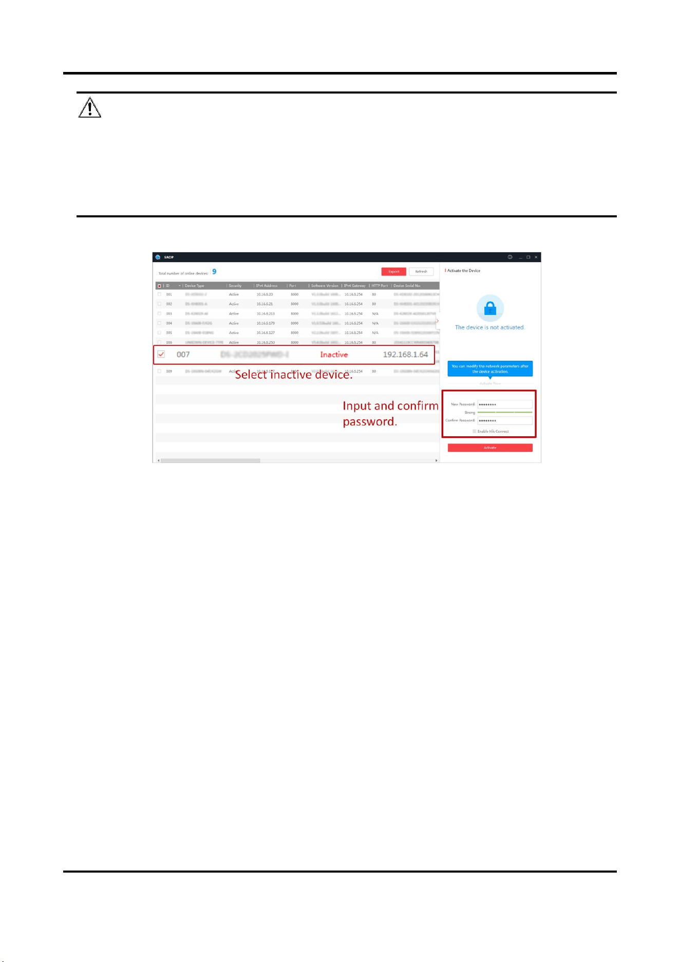
Steps
1. Run the SADP software and search the online devices.
2. Find and select your device in online device list.
3. Enter a new password (admin password) and confirm the password.
Radar-Assisted Traffic Camera User Manual
3
Caution
STRONG PASSWORD RECOMMENDED-We highly recommend you create a strong password of
your own choosing (using a minimum of 8 characters, including upper case letters, lower case
letters, numbers, and special characters) in order to increase the security of your product. And
we recommend you reset your password regularly, especially in the high security system,
resetting the password monthly or weekly can better protect your product.
4. Click Activate to start activation.
Status of the device becomes Active after successful activation.
5. Modify IP address of the device.
1) Select the device.
2) Change the device IP address to the same network segment as your computer by either
modifying the IP address manually or checking Enable DHCP.
3) Enter the admin password and click Modify to activate your IP address modification.
2.1.3 Activate via Web Browser
Use web browser to activate the device. For the device with the DHCP enabled by default, use
SADP software or client software to activate the device.
Before You Start
Ensure the device and the computer connect to the same LAN.
Steps
1. Change the IP address of your computer to the same network segment as the device.
2. Open the web browser, and enter the default IP address of the device to enter the activation
interface.
3. Create and confirm the admin password.

Radar-Assisted Traffic Camera User Manual
4
Caution
STRONG PASSWORD RECOMMENDED-We highly recommend you create a strong password of
your own choosing (using a minimum of 8 characters, including upper case letters, lower case
letters, numbers, and special characters) in order to increase the security of your product. And
we recommend you reset your password regularly, especially in the high security system,
resetting the password monthly or weekly can better protect your product.
4. Click OK to complete activation.
5. Go to the network settings interface to modify IP address of the device.
2.2 Login
You can log in to the device via web browser for further operations such as live view and local
configuration.
Before You Start
Connect the device to the network directly, or via a switch or a router.
Steps
1. Open the web browser, and enter the IP address of the device to enter the login interface.
2. Enter User Name and Password.
3. Click Login.
4. Download and install appropriate plug-in for your web browser. Follow the installation prompts
to install the plug-in.
5. Reopen the web browser after the installation of the plug-in and repeat steps 1 to 3 to login.
6. Optional: Click Logout on the upper right corner of the interface to log out of the device.
Radar-Assisted Traffic Camera User Manual
5
Chapter 3 Radar Detection
Radar is used to detect the target and link the capture. Set radar detection parameters before
capturing vehicle pictures.
Note
The function varies with different models. The actual device prevails.
3.1 Set Detection Parameters
Set radar detection parameters before capturing vehicle pictures.
Steps
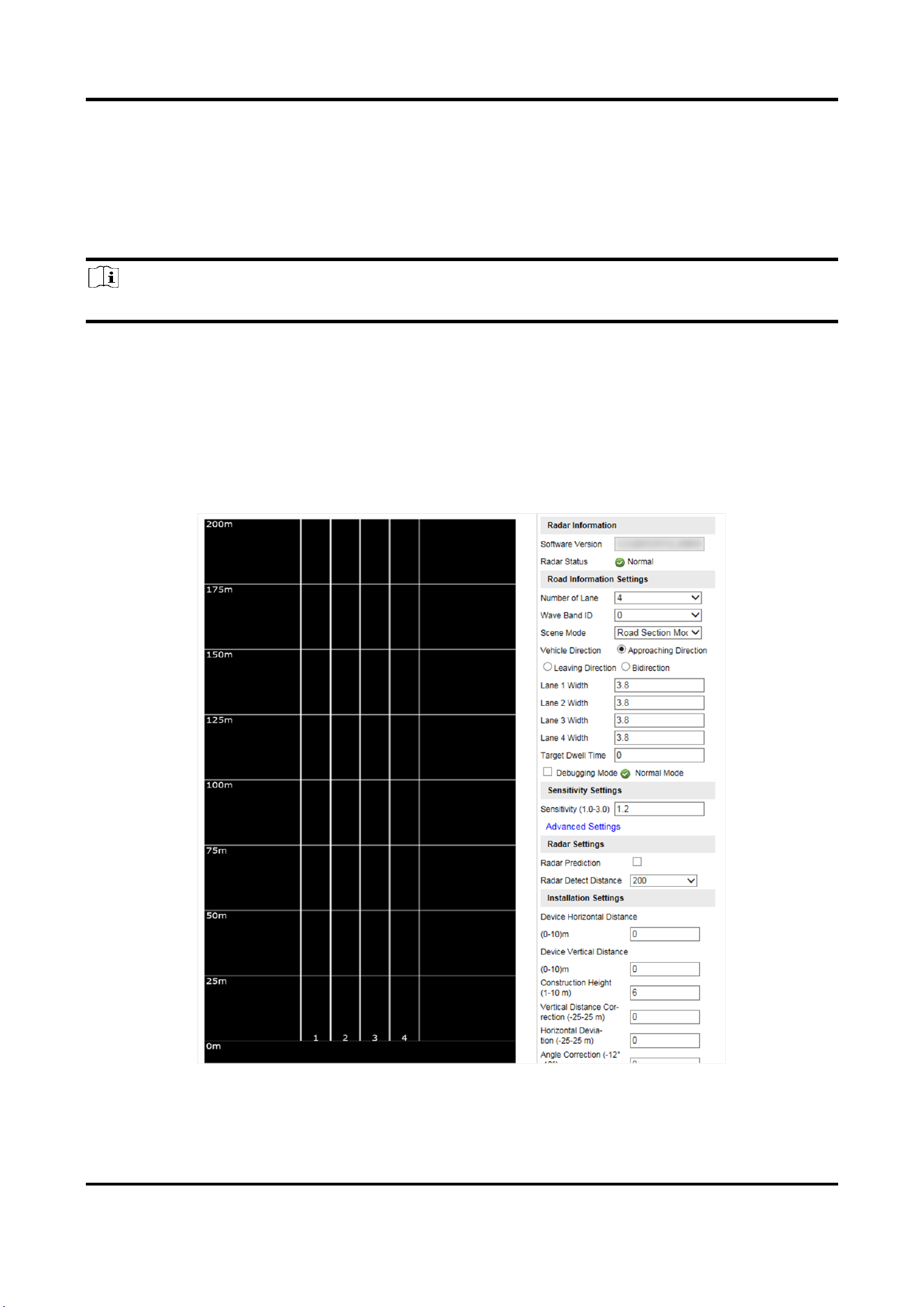
1. Click Radar.
Figure 3-1 Set Radar Detection Parameters
2. View the radar information.

Radar-Assisted Traffic Camera User Manual
6
Software Version
The software version of the radar.
Radar Status
The current radar status. The radar can be normally used in normal status. If the radar is in
upgrading status, do not reboot the device. Refresh the interface every one minute, and the
status can be restored to normal.
3. Set the road information.
Number of Lane
Select it according to the actual scene.
Wave Band ID
0 to 4 stand for five frequencies. No need to set the wave band ID in normal conditions. But
you need to set it when there are many vehicle detectors in the same road segment and the
detection areas are overlapped, to guarantee the wave band IDs of the vehicle detectors
covered by the detection areas are different.
Scene Mode
Select it according to the actual scene.
Vehicle Detection
Approaching Direction
The vehicles are driven towards the construction position of the vehicle detector.
Leaving Direction
The vehicles are driven far away from the construction position of the vehicle detector.
Bidirection
There are vehicles driven both towards and far away from the construction position of the
vehicle detector.
Lane Width
The width ranges from 3 to 6 m.
Target Dwell Time
When the target stays for a duration exceeding the set dwell time, the device will remove the
corresponding target rectangles automatically. The targets will not be counted in vehicle data
statistics.
Debugging Mode
Check it to enable the radar debug mode. In this mode, the vehicles outside the drawn area
will be displayed, to make it convenient to debug the radar.
4. Set the sensitivity.
1) Enter Sensitivity.

Radar-Assisted Traffic Camera User Manual
7
Note
The lower the sensitivity is, the more sensitive the detection will be. For the detection which
is too sensitive (e.g., some fixed facilities such as the bus station on the lane are detected as
vehicles), you can adjust the sensitivity higher.
2) Click Advanced Settings to set the influential range and sensitivity.
Influential Range
If you do not want to adjust the total sensitivity, enter the vertical distance from the
possible mistakenly recognized area (such as the bus station) to the vehicle detector.
Sensitivity
You can adjust the sensitivity of each influential range independently.
Note
The influential range of the sensitivity can be set every 50 m, and up to four areas can be set.
5. Set the installation parameters.
Construction Height
The construction height of the camera.
Horizontal Deviation
The horizontal distance from the radar to the central point of all the detected roads. E.g., if
the radar detects three lanes, and is installed in the center of the central lane, then the
horizontal deviation is 0. If the radar is not installed in the center, you need to set the value.
Angle Correction
To correct the angle between the radar and the approaching direction of the vehicle. E.g., if
the radar detects three lanes, and is installed in the center of the central lane without
deflection, then the angle correction is 0. If the radar is not installed in the center, and there
is deflection comparing with the central installation, you need to set the value.
Note
Keep the default value of Vertical Distance Correction and Distance to Stop Line.
6. Click Settings to save the settings.
Radar-Assisted Traffic Camera User Manual
8
3.2 Set Radar Calibration
Calibrate radar after the radar detection parameters are set to display the targets detected by the
radar on the video.
Before You Start
Enable Rule Information in Configuration → Local Configuration.
Steps
1. Click Radar.
2. Click Radar Calibration.
3. Select Calibration Mode and set the radar calibration.
–
Select Coordinate Mode. Refer to Coordinate Mode for details.
–
Select Auto Calibration Mode. Refer to Auto Calibration Mode for details.
Note
The supported calibration modes vary with different models. The actual device prevails.
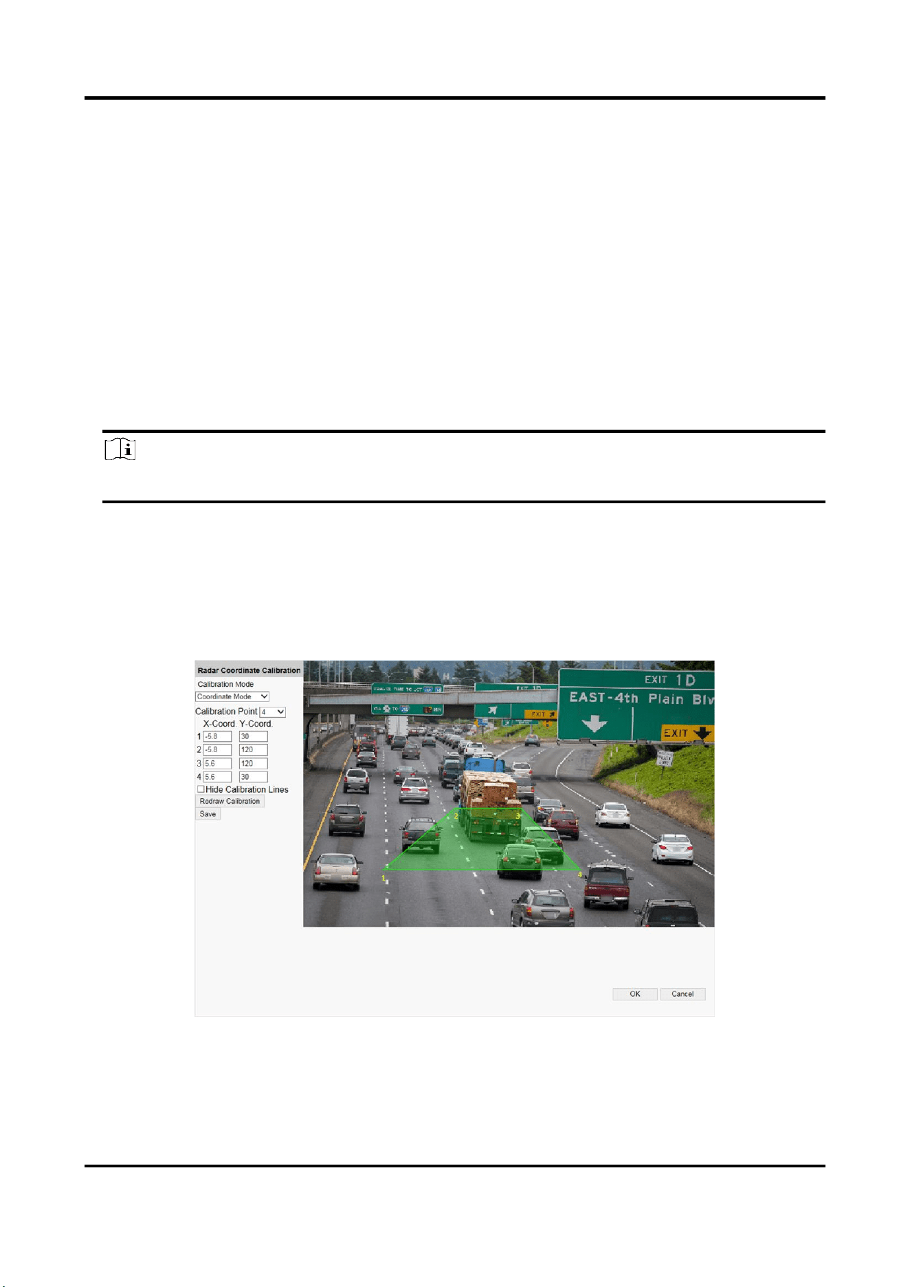
3.2.1 Coordinate Mode
Steps
1. Select Calibration Mode as Coordinate Mode.
Figure 3-2 Coordinate Mode
2. Select Calibration Point.
3. Draw the calibration area.

Radar-Assisted Traffic Camera User Manual
9
1) Click Redraw Calibration.
2) Click the left button of the mouse to locate the vertexes of the calibration area on the live
view image, and click the right button of the mouse to finish the drawing.
Note
The number of vertexes should be consistent with the selected number of Calibration Point.
3) Drag the vertexes of the calibration area to align it to the lanes.
Note
If the lanes cannot be aligned, ensure the calibration area can contain the detection area.
4. Measure the world coordinates of the vertexes, and enter the values in the corresponding
coordinate text fields.
Note
The world coordinate origin is the central point of the radar. The Y-coordinate of the central
point locates in the horizontal pole where the radar is installed, and the X-coordinate of the
central point locates in the central point of all the detected roads. E.g., if the calibration area
covers three lanes, and the lane width is 2 m, 4 m, and 4 m respectively, then the X-coordinate
of the central point locates in the 5 m position, and the X-coordinate of the far left lane and far
right lane is -5 and 5 respectively.
5. Adjust the radar in two ways if the coordinates fed back from the radar cannot be matched with
the measured coordinates when the vehicle passes the calibration position.
–
Adjust the radar until it can feed back the correct position.
–
Adjust the X-coordinates of the calibration points to make them adapt to the coordinates fed
back from the radar. The method is to enter the X-coordinates fed back from the radar into
the corresponding text fields when the vehicle passes the far left or far right. Adjust finely if
there is small deviation to guarantee the radar frames and the video frames can be matched
in the field of view.
6. Optional: Check Hide Calibration Lines to hide the lines on the live view image.
7. Click Save.
8. Click OK to exit.
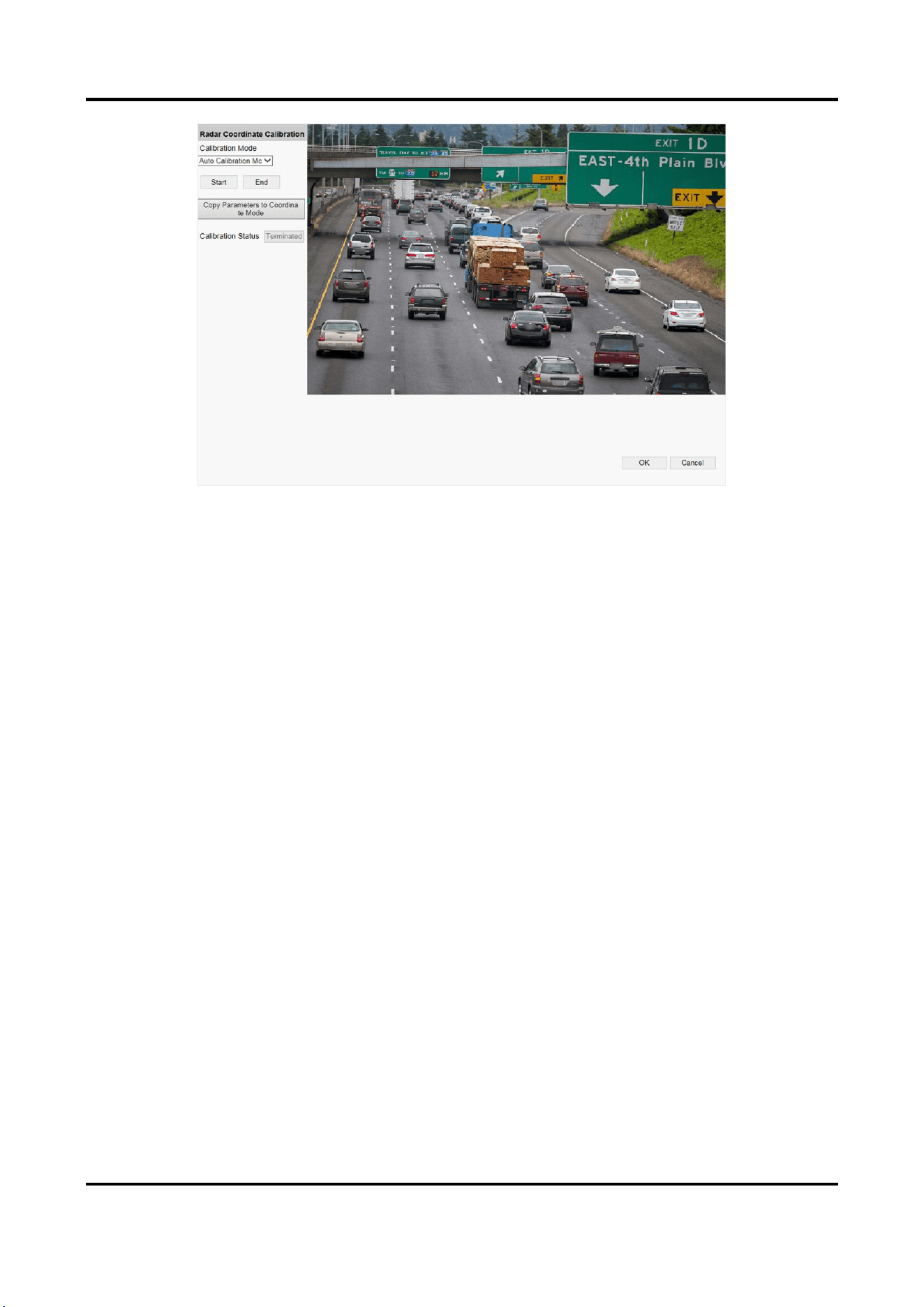
3.2.2 Auto Calibration Mode
Steps
1. Select Calibration Mode as Auto Calibration Mode.
Radar-Assisted Traffic Camera User Manual
10
Figure 3-3 Auto Calibration Mode
2. Click Start.
The auto calibration starts, and you can view the calibration status and progress. 100% means
the auto calibration is finished.
3. Optional: Click End if the calibration effect has met the requirement during the process.
4. Optional: Click Copy Parameters to Coordinate Mode to copy the auto calibrated coordinates to
the coordinate mode.
5. Click OK.
Radar-Assisted Traffic Camera User Manual
11
Chapter 4 Vehicle Capture
Note
The supported trigger modes vary with different models. The actual device prevails.
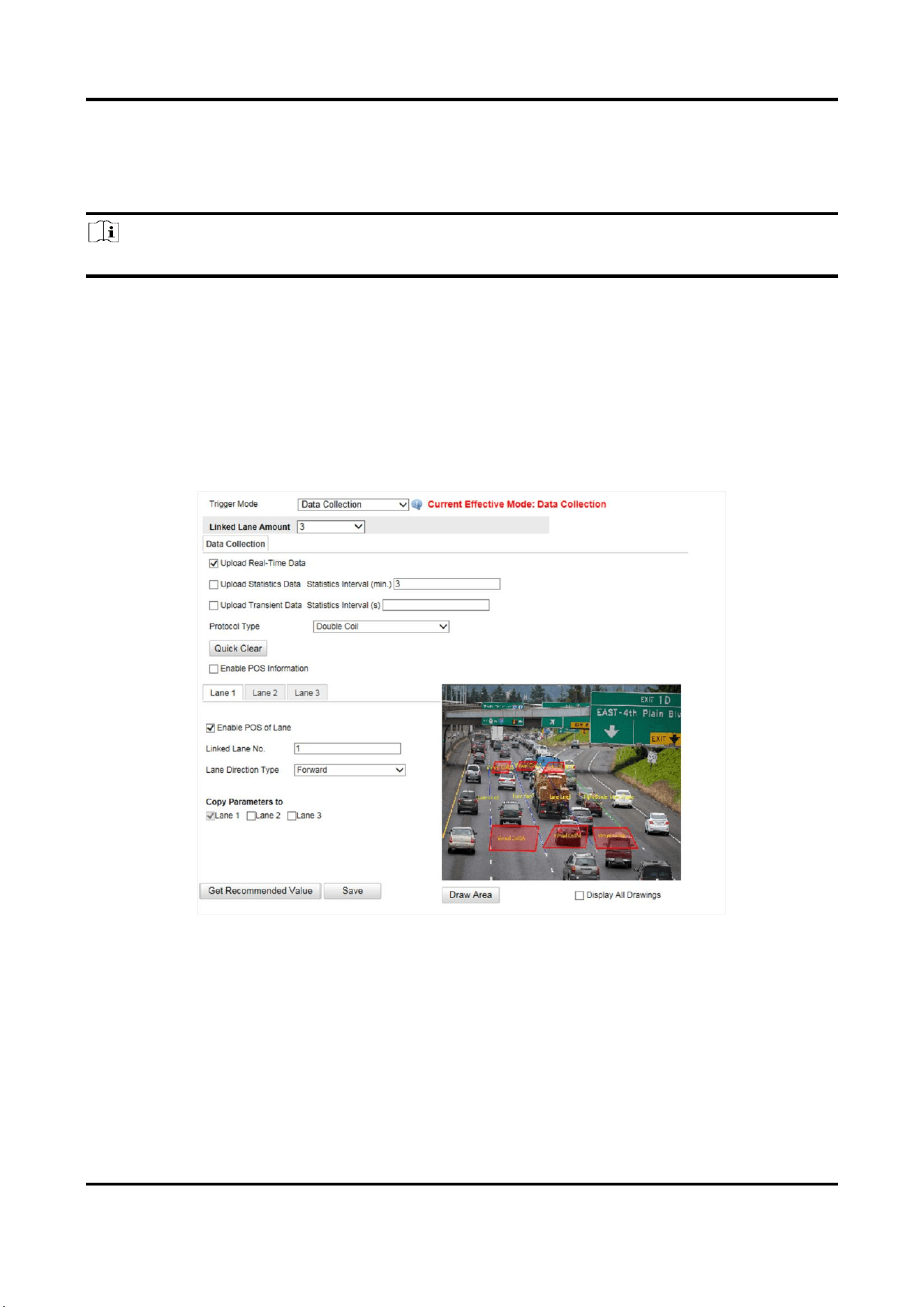
4.1 Set Data Collection
You can set the vehicle data collection and analysis parameters.
Steps
1. Go to Configuration → Device Configuration → Application Mode → Trigger Mode.
2. Select Trigger Mode as Data Collection.
Figure 4-1 Set Data Collection
3. Select Linked Lane Amount.
4. Select data upload mode.
Upload Real-Time Data
The vehicle detector will upload the collected data to the server in real time.
Upload Statistics Data
The vehicle detector will upload the collected data to the server according to the set interval.

Radar-Assisted Traffic Camera User Manual
12
Upload Transient Data
The vehicle detector will upload the collected transient data to the server according to the set
interval.
5. Select Protocol Type.
Unicoil
One coil for each lane.
Double Coil
Two coils for each lane.
6. Enable POS information.
1) Check Enable POS Information.
2) Enter X-Coord. and Y-Coord. of the POS information overlaid on the live view image.
3) Check the POS information to overlay on the live view image.
4) Optional: Click Quick Clear to refresh the POS information on the live view image.
7. Set the lane data collection parameters.
1) Click the lane No.
2) Check Enable POS of Lane to enable the POS information collection of the lane.
3) Enter Linked Lane No.
4) Select Lane Direction Type.
5) Optional: Check lane(s) to copy the parameters of the current lane to other lane(s).
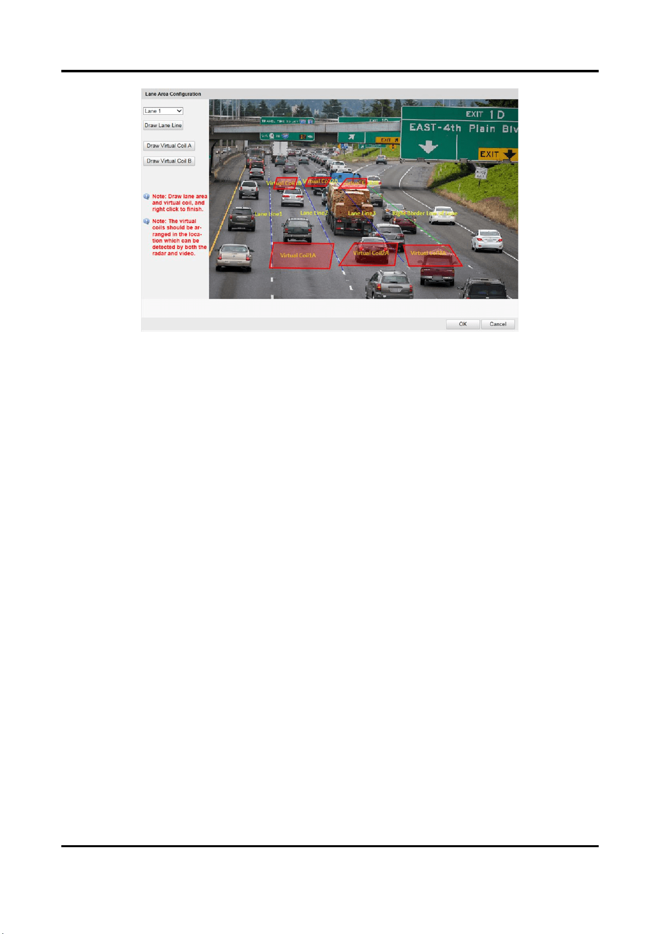
8. Draw lane lines and virtual coil areas.
1) Click Draw Area.
2) Select the lane.
3) Select the default lane lines and right border line, and drag the two end points of the line or
drag the whole line to adjust its position according to the actual scene.
4) Optional: Click Draw Lane Line to restore to the default drawing.
5) Click Draw Virtual Coil A/B to draw the virtual coil area.
Note
●
Click the left button of the mouse to locate the vertexes of the virtual coil area on the live
view image, and click the right button of the mouse to finish the drawing.
●
It is recommended to draw the virtual coil A at the position the distance from which to the
image lower edge is the length of two vehicles, and the virtual coil B at the position the
distance from which to coil A is 20 to 30 m.
6) Click OK.
Radar-Assisted Traffic Camera User Manual
13
Figure 4-2 Draw Lane Lines and Virtual Coil Areas
9. Click Save.
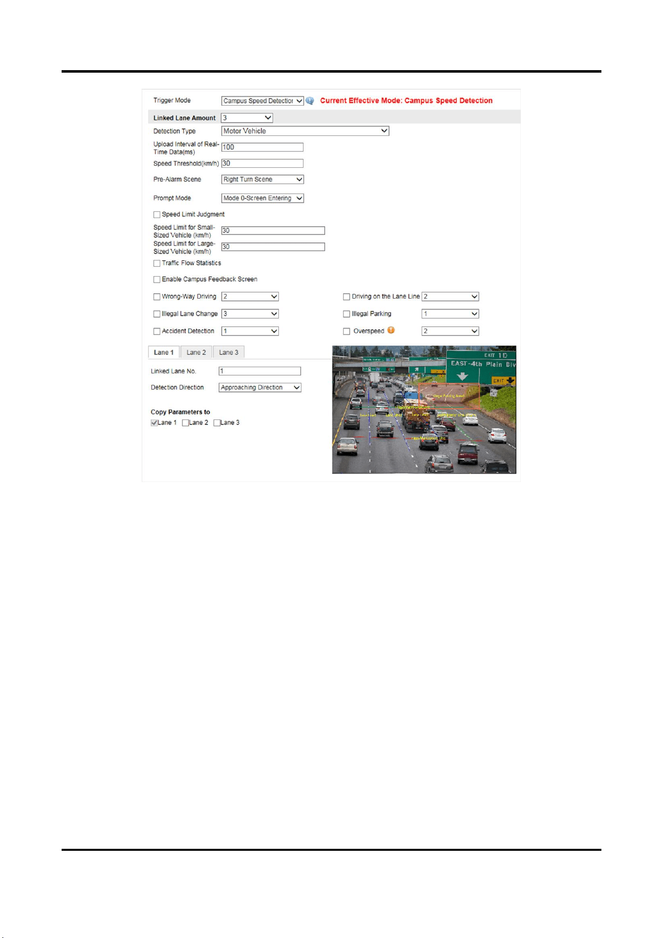
4.2 Set Campus Speed Detection
You can set the speed prompt on the campus feedback screen and set the speed detection
parameters.
Steps
1. Go to Configuration → Device Configuration → Application Mode.
2. Select Trigger Mode as Campus Speed Detection.
Radar-Assisted Traffic Camera User Manual
14
Figure 4-3 Set Campus Speed Detection
3. Select Linked Lane Amount.
4. Set detection type and speed limit parameters.
Detection Type
Select motor vehicle, non-motor vehicle, or pedestrian to detect the speed.
Upload Interval of Real-Time Data
The detected speed information will be uploaded to the server in real time according to the
set interval.
Speed Threshold
When the speed of the detected target exceeds the threshold, it is regarded as overspeed,
and more than one picture will be captured.
Pre-Alarm Scene
Select the scene of triggering pre-alarm.
Prompt Mode
Mode 0-Screen Entering Accuracy Priority

Radar-Assisted Traffic Camera User Manual
15
The speed and license plate information will prompt when the vehicle is at the capture
triggering line.
Mode 1-Screen Entering Timeliness Priority
The speed and license plate information will prompt when the vehicle is at the prompt
triggering line.
Mode 2-Single Lane Dynamic Speed Detection
The speed and license plate information of the first vehicle will display in real time during
the vehicle is passing between the prompt triggering line and capture triggering line.
Speed Limit Judgment
Check it to judge the speed limit and set Speed Limit for Small-Sized Vehicle and Speed Limit
for Large-Sized Vehicle. When the vehicle speed exceeds the set limit, the speed information
will be displayed as red on the feedback screen, and green when the speed does not exceed
the limit.
Traffic Flow Statistics
Check it and set the interval. Then the traffic flow will be counted according to the set
interval.
5. Set the campus feedback screen.
1) Check Enable Campus Feedback Screen .
2) Set the IP address and port of the screen.
3) Select Screen Type.
Vehicle Speed Screen
For the vehicle speed screen, Default Content on the screen cannot be edited.
Vehicle License Plate and Speed Screen
For the vehicle license plate and speed screen, you can set Default Content on the screen.
Up to four characters are supported.
4) Set Display Color and Display Time.
6. Check the event detection types, and set the number of captured pictures and corresponding
parameters.
Note
For the detection sensitivity, if there are many mistaken captures, you can adjust it smaller, and
if there are many missing captures, you can adjust it larger.
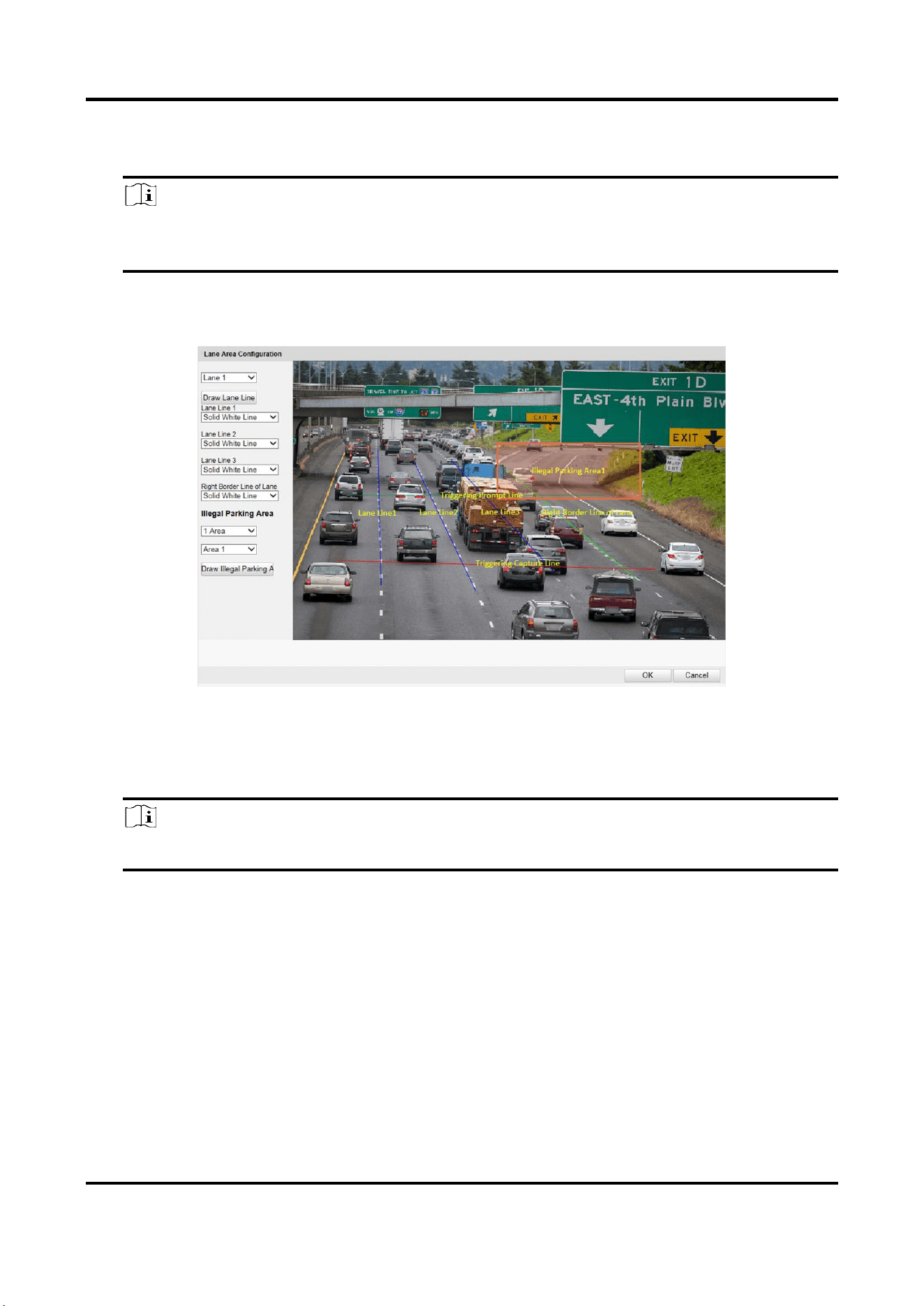
7. Draw lane lines and illegal parking areas.
1) Click Draw Area.
2) Select the lane.
3) Set the property of the lane lines and right border line.
4) Select the default lane lines and right border line, and drag the two end points of the line or
drag the whole line to adjust its position according to the actual scene.
5) Optional: Click Draw Lane Line to restore to the default drawing.
Radar-Assisted Traffic Camera User Manual
16
6) Select Illegal Parking Area.
7) Select the illegal parking area No., and click Draw Illegal Parking Area to draw the area.
Note
Click the left button of the mouse to locate the vertexes of the area on the live view image,
and click the right button of the mouse to finish the drawing.
8) Select another area No. and draw the area according to the steps above.
9) Click OK.
Figure 4-4 Draw Lane Lines and Illegal Parking Areas
8. Set the lane parameters.
1) Select Linked Lane No.
2) Select Detection Direction.
Note
The detection directions of multiple lanes should be consistent.
3) Optional: Check lane(s) to copy the parameters of the current lane to other lane(s).
9. Click Save.
Radar-Assisted Traffic Camera User Manual
17
4.3 Set Capture Parameters
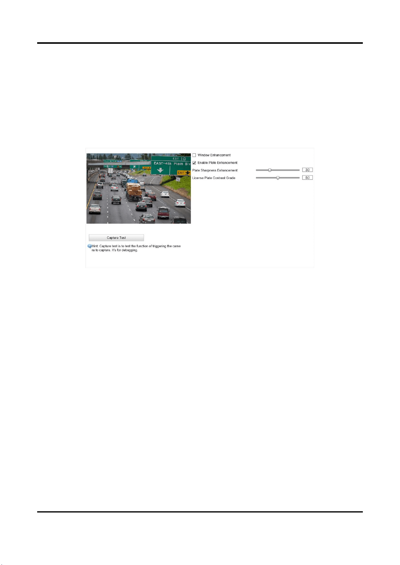
4.3.1 Set Captured Image Parameters
Set the parameters of captured images to raise the image quality.
Steps
1. Go to Configuration → Device Configuration → Image Parameters → Capture.
Figure 4-5 Set Captured Image Parameters
2. Set the captured image parameters.
Window Enhancement
In front light or back light scene, the flash light may not pass through the vehicle window, or
the image effect of the window is bad caused by the light. In this condition, you can check
Window Enhancement. The higher the Brightness Enhancement Level is, the brighter the
window image is. The higher the Defog Level is, the better the permeability of the window
image is.
Enable Plate Enhancement
Check Enable Plate Enhancement to capture clearer license plate images. The higher the
Plate Sharpness Enhancement and License Plate Contrast Grade are, the clearer the
captured license plate images are. But if the level is too high, the captured images may be
overexposed. It is recommended to save the default level.
Radar-Assisted Traffic Camera User Manual
18
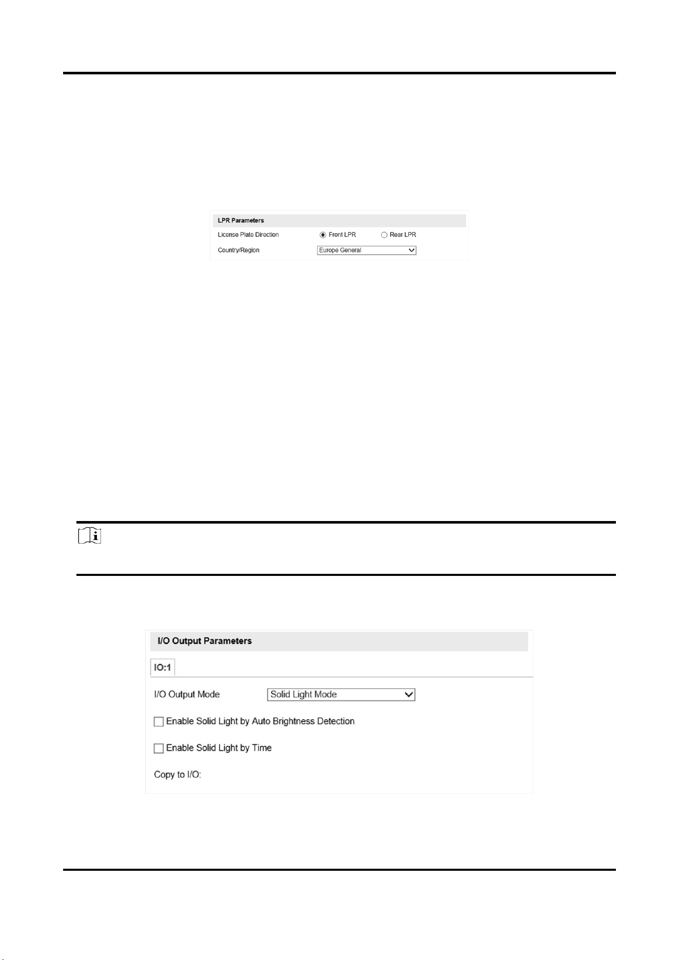
4.3.2 Set License Plate Recognition Parameters
When there are vehicles of different types passing from different directions, set the license plate
recognition parameters.
Steps
1. Go to Configuration → Device Configuration → Capture Parameters → LPR Parameters.
Figure 4-6 Set License Plate Recognition Parameters
2. Select License Plate Direction.
–
Select Front LPR when license plates of vehicles from the approaching direction need to be
recognized.
–
Select Rear LPR when license plates of vehicles from the leaving direction need to be
recognized.
3. Set Country/Region according to the actual needs.
4. Click Save.
4.3.3 Set Supplement Light Parameters
Supplement light can enhance the image stabilization and adjust the brightness and color
temperature. You can use supplement light to supplement light at night or when the light is dim.
Steps
Note
Only when the solid light is connected, can the set parameters take effect.
1. Go to Configuration → Device Configuration → Capture Parameters → Supplement Light
Parameters.
Figure 4-7 Set Supplement Light Parameters
Radar-Assisted Traffic Camera User Manual
19
2. Set the solid light output mode.
–
Check Enable Solid Light by Auto Brightness Detection when you want the solid light to be
controlled by detecting the surroundings brightness automatically. Set the brightness
threshold. The higher the threshold is, the harder the solid light can be enabled.
–
Check Enable Solid Light by Time when you want the solid light to be enabled during a fixed
time period. Set the start time and end time.
Note
Enabling solid light by brightness and time are conflicted with each other. You can only enable
one function.
3. Click Save.
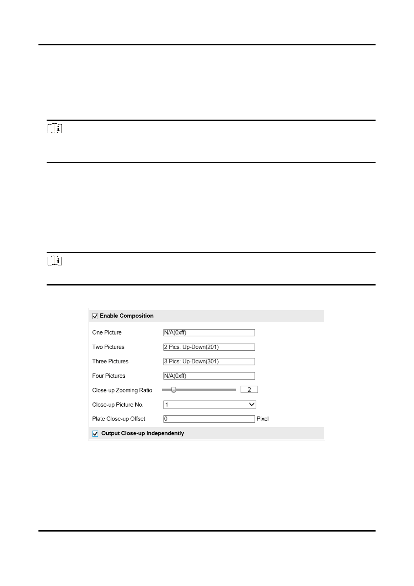
4.3.4 Set Picture Composition
You can enable the picture composition to composite several pictures into one to make it
convenient to view the violation captured pictures.
Steps
Note
Functions and parameters vary with different models. The actual device prevails.
1. Go to Configuration → Device Configuration → Capture Parameters → Picture Composition.
Figure 4-8 Set Picture Composition
2. Check Enable Composition.
3. Set composition types for different picture quantities.
4. Set other composition parameters.
Radar-Assisted Traffic Camera User Manual
20
Note
The default value of Plate Close-up Offset is 0, which is recommended to be adopted. The
device can capture close-up pictures according to the set offset when no license plate is
recognized.
5. Optional: Check Output Close-up Independently to output close-up pictures independently
when the picture composition is not enabled.
6. Click Save.
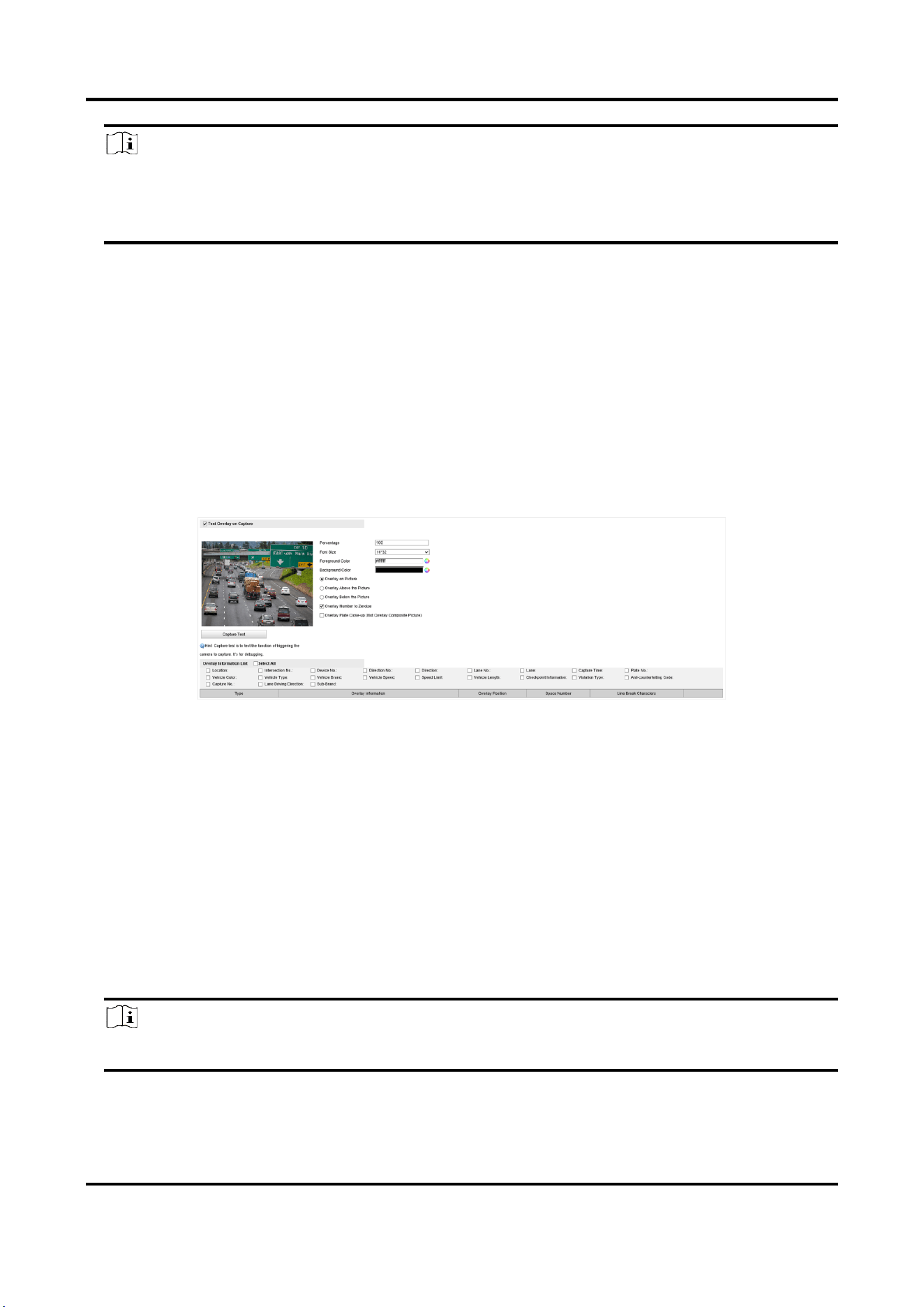
4.3.5 Set Capture Overlay
If you want to overlay information on the captured pictures, set capture overlay.
Steps
1. Go to Configuration → Device Configuration → Text Overlay → Capture Overlay Configuration.
2. Check Text Overlay on Capture.
Figure 4-9 Set Capture Overlay
3. Set the percentage, front size, color, overlay position, etc.
Percentage
It is the percentage that the overlaid information occupies on the picture. For example, if you
set the percentage to 50, the overlaid information in a row will occupy up to half of the image
width, and the excess content will be overlaid from a new line.
Overlay Number to Zeroize
When the overlaid number digits are smaller than the fixed digits, 0 will be overlaid before
the overlaid number. E.g., the fixed digits for lane No. is 2. If the lane No. is 1, 01 will be
overlaid on the picture.
4. Select the overlay information from the list.
Note
The overlay information varies with different models. The actual device prevails.
5. Set the overlay information.

Radar-Assisted Traffic Camera User Manual
21
Set Type
You can edit the type.
Set Overlay
Information
For some information type, you can edit the detailed information.
Set Overlay Position
If you select Overlay on the Picture, you can check it. Then the
current information will be displayed from a new line.
Set Space Number
Edit the number of space between the current information and the
next one from 0 to 255. 0 means there is no space.
Set Line Break
Characters
Edit the number of characters from 0 to 100 between the current
information line and the previous information line. 0 means no line
break.
Adjust overlay
sequence
Click / to adjust the display sequence of the overlay
information.
6. Click Save.
4.3.6 Set Composite Picture Overlay
If you want to overlay information on the composite pictures, set composite picture overlay.
Steps
1. Go to Configuration → Device Configuration → Text Overlay → Composite Picture Overlay
Configuration.
2. Check Text Overlay on Capture.
Figure 4-10 Set Capture Overlay
3. Set the font size, color, overlay position, etc.
Percentage
It is the percentage that the overlaid information occupies on the picture. For example, if you
set the percentage to 50, the overlaid information in a row will occupy up to half of the image
width, and the excess content will be overlaid from a new line.
4. Select the overlay information from the list.

Radar-Assisted Traffic Camera User Manual
22
Note
The overlay information varies with different models. The actual device prevails.
5. Set the overlay information.
Set Type
You can edit the type.
Set Overlay
Information
For some information type, you can edit the detailed information.
Set Overlay Position
If you select Overlay on the Picture, you can check it. Then the
current information will be displayed from a new line.
Set Space Number
Edit the number of space between the current information and the
next one from 0 to 255. 0 means there is no space.
Set Line Break
Characters
Edit the number of characters from 0 to 100 between the current
information line and the previous information line. 0 means no line
break.
Adjust overlay
sequence
Click / to adjust the display sequence of the overlay
information.
6. Click Save.
4.3.7 Set Traffic Light Synchronization
If you want to synchronize the shutter with the traffic light, enable the traffic light
synchronization.
Steps
Note
Some models do not support traffic light synchronization. The actual device prevails.
1. Go to Configuration → Device Configuration → Capture Parameters → Traffic Light
Synchronization.
2. Check Enable Traffic Light Synchronization.
3. Set the phase and signal frequency according to the prompts.
4. Click Save.
Radar-Assisted Traffic Camera User Manual
23
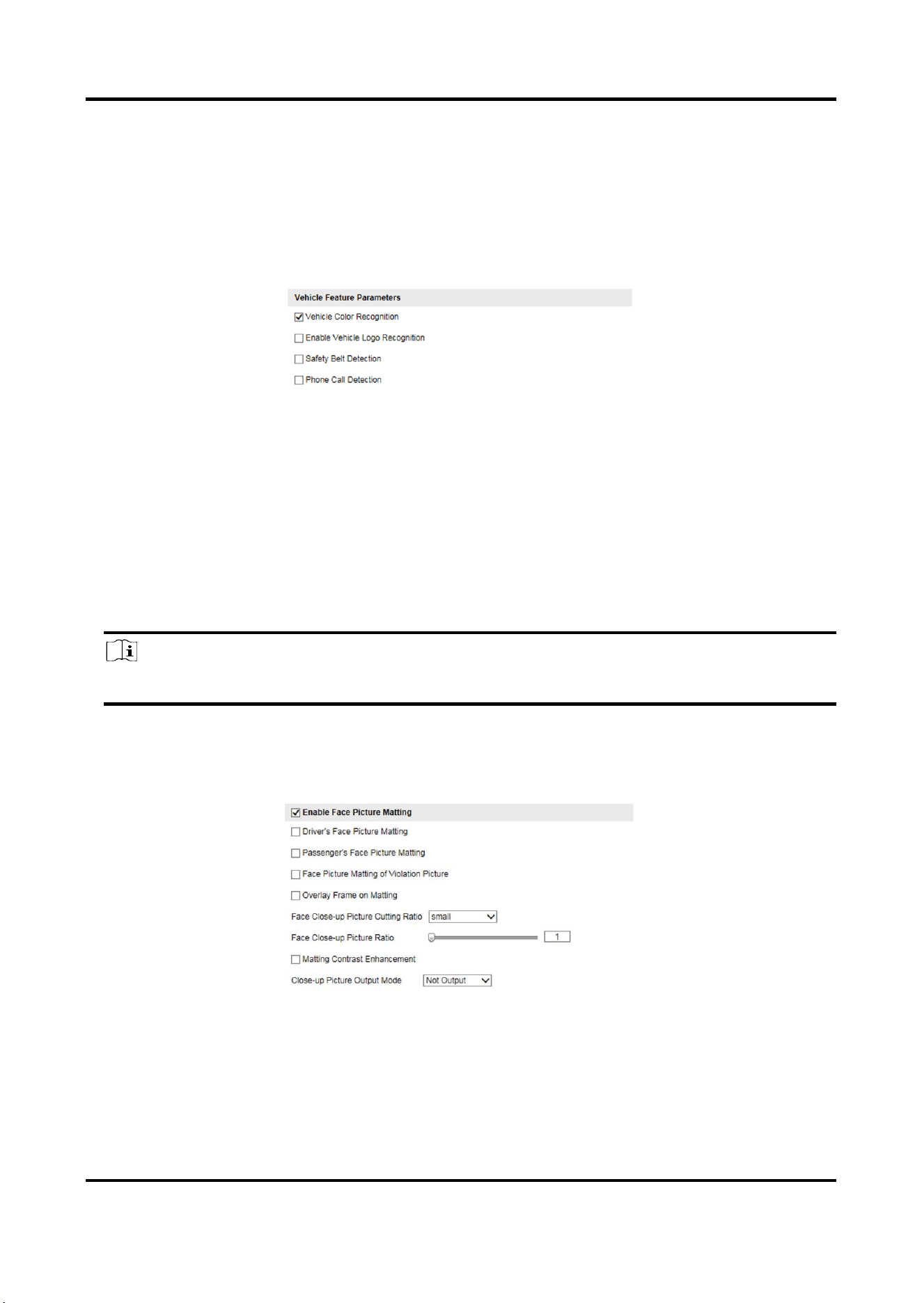
4.3.8 Set Vehicle Feature Parameters
Set vehicle feature parameters if you need to detect the vehicle features of the passing vehicle.
Steps
1. Go to Configuration → Device Configuration → Capture Parameters → Vehicle Feature
Parameters.
Figure 4-11 Set Vehicle Feature Parameters
2. Check the vehicle features that needed to be detected.
3. Click Save.
4.3.9 Set Face Picture Matting
You can enable driver's or passenger's face picture matting on the capture violation pictures and
set corresponding parameters.
Steps
Note
Some models do not support face picture matting. The actual device prevails.
1. Go to Configuration → Device Configuration → Capture Parameters → Vehicle Feature
Parameters.
2. Check Enable Face Picture Matting.
Figure 4-12 Set Face Picture Matting
3. Set corresponding parameters.
Driver's/Passenger's Face Picture Matting
Select the driver's or passenger's face picture to be detected.

Radar-Assisted Traffic Camera User Manual
24
Face Picture Matting of Violation Picture
Check it to cutout the face picture on the captured violation picture.
Overlay Frame on Matting
Check it to overlay frame on the matted picture.
Face Close-up Picture Cutting Ratio
Select the cutting ratio of the face close-up picture to be small, middle, or large.
Face Close-up Picture Ratio
Adjust the zooming ratio of the face close-up picture.
Matting Contrast Enhancement
Check it to enable the function and set the level. The higher the level is, the stronger the
contrast between the matting and the overlaid picture will be.
Close-up Picture Output Mode
Overlay on Picture
The driver's face close-up picture will be overlaid on the upper right corner of the picture,
and the passenger's face close-up picture will be overlaid on the upper left corner of the
picture.
Upload Arm
The face close-up pictures will be uploaded to the arming host or listening host.
Overlay and Upload Arm
The face close-up pictures will both be overlaid on the pictures and uploaded to the arming
host or listening host.
4. Click Save.
Result
If level 1 arming is set for the camera, the face close-up pictures will be uploaded to the level 1
arming device. If only level 2 arming is set for the camera, the face close-up pictures will both be
stored in the local storage and uploaded to the level 2 arming device.
4.3.10 Set Image Encoding Parameters
If the captured pictures are not clear, set the resolution of the captured pictures and the picture
size.
Steps
1. Go to Configuration → Device Configuration → Encoding and Storage → Image Encoding.
Radar-Assisted Traffic Camera User Manual
25
Figure 4-13 Set Image Encoding Parameters
2. Select Capture Resolution.
3. Enter the picture size.
JPEG Picture Size
The size of the captured picture.
Composite JEPG Picture Size
The size of the composite picture.
4. Click Save.
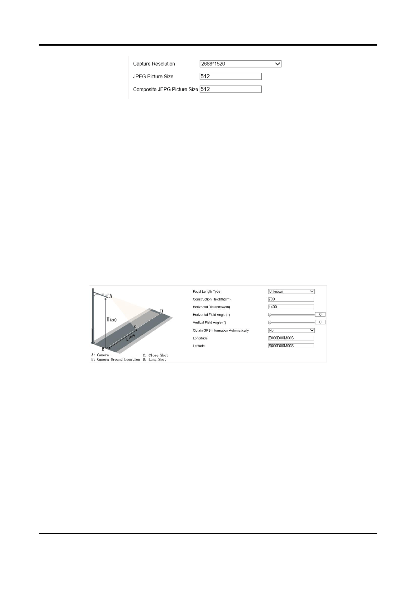
4.3.11 Set Construction Parameters
Set construction parameters according to the actual installation when applying the video speed
detection.
Steps
1. Go to Configuration → Device Configuration → System → Construction Parameters.
Figure 4-14 Set Construction Parameters
2. Set construction parameters according to the actual scene.
3. Click Save.

Radar-Assisted Traffic Camera User Manual
26
4.3.12 Set Violation Dictionary
Violation dictionary defines corresponding codes of violation types. You can set the violation code,
violation type, and violation description in this section. The default parameters are recommended.
Steps
Note
Functions and parameters vary with different models. The actual device prevails.
1. Go to Configuration → Device Configuration → System → Violation Dictionary.
2. Set Violation Code, Violation Type, and Violation Description according to the actual needs.
3. Click Save.
Result
The violation code and description will be displayed on the captured picture when the
corresponding violation happens.
4.3.13 Set Upload Protocol
You can control the picture types to be uploaded by selecting different upload protocols.
Steps
1. Go to Configuration → Device Configuration → Encoding and Storage → Upload Protocol.
Figure 4-15 Set Upload Protocol
2. Check an upload protocol.
License Plate Upload Protocol
Only the license plate pictures will be uploaded.
Mixed Target Upload Protocol
Both the license plate and face pictures will be uploaded. If you check Enable Body Property,
the body property information will be overlaid on the uploaded face pictures.
3. Click Save.
4.4 View Real-Time Picture
You can view the real-time captured pictures and license plate information.
Steps
1. Go to Live View → Real-Time Status and Traffic Flow Statistics.
Radar-Assisted Traffic Camera User Manual
27
2. Select an item from the list, and you can view the capture scene picture and license plate
picture.
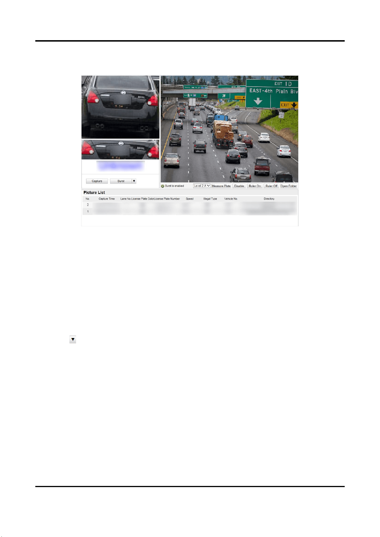
Figure 4-16 Real-Time Picture
3. You can do the following operations on this interface.
–
Select the arming mode. Level 1 Arming can only connect one client or web. The uploaded
pictures will not be stored in the storage card. The pictures in the storage card will be
uploaded to the level 1 arming. Level 2 Arming can connect three clients or webs. The
pictures will be uploaded to the client/web, and stored in the storage card. Disarm is to
cancel the alarm status or real-time picture.
–
Click Capture to enable manual capture. The captured pictures will be saved in the set local
path. Or you can click Open Folder to view the pictures.
–
Click Measure Plate/Ruler On to measure the license plate pixel. After the measurement,
click Disable/Ruler Off.
–
Click after Burst to set the burst parameters.
Pictures Per Burst
Up to five pictures can be captured per burst.
Burst Interval
Up to four intervals can be set, and the default interval is 100 s.
Click Burst, and the device will capture pictures according to the set intervals.

Radar-Assisted Traffic Camera User Manual
28
4.5 Search Picture
You can search the captured pictures stored in the storage card and export the pictures you need.
Before You Start
Install the storage card, and ensure the storage status is normal.
Steps
1. Click Picture.
2. Set the search conditions such as Lane No., Vehicle Type, etc.
3. Click Search.
The searched pictures information will be displayed in the picture list.
Note
If you have set level 1 arming for the device, the captured pictures will not be saved in the
storage card. Go to the saving path of scene pictures to view them. You can go to Configuration
→ Local Configuration to get the saving path.
4. Optional: Click to preview the selected picture.
You can view the captured picture and the related information such as the capture time, lane
No., license plate number, etc.
5. Optional: Check a picture or several pictures and click Export Picture to export it/them to the
saving path you have set.
The downloaded picture(s) will be marked as "Downloaded". You can go to Configuration →
Local Configuration to get the saving path of downloaded pictures.
4.6 Set Guidance Screen
You can set the guidance screen to display the license plate, vehicle speed, and slogan
information.
Steps
Note
The guidance screen function varies with different models. The actual device prevails.
1. Go to Configuration → Device Configuration → Guidance Screen.
2. Select the screen.
3. Check Enable.
Radar-Assisted Traffic Camera User Manual
29
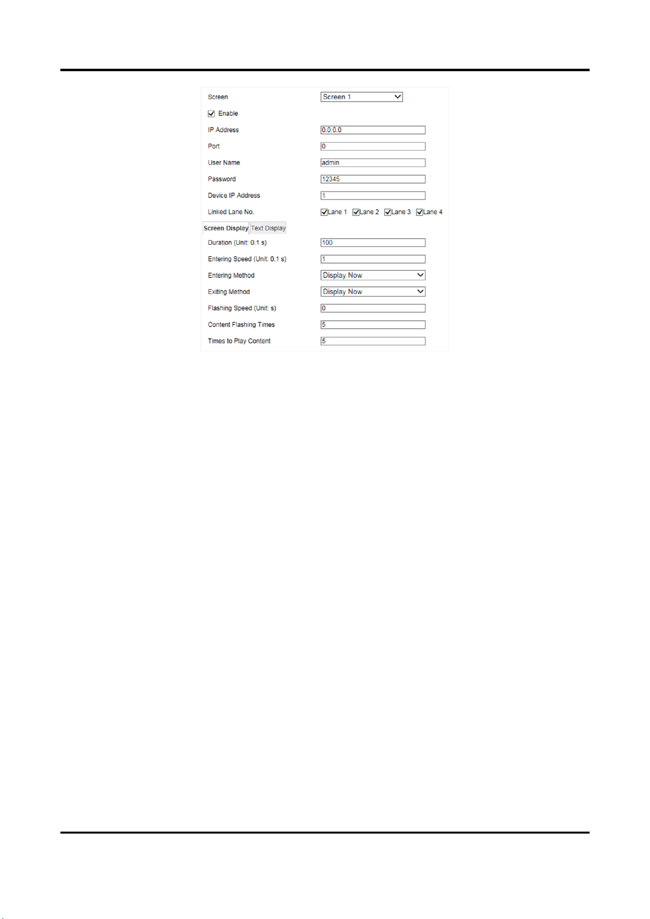
Figure 4-17 Set Guidance Screen
4. Set the screen parameters such as the IP address, port, user name, etc.
5. Select Linked Lane No.
6. Click Screen Display to set the display parameters.
Duration
The display duration of the captured text information.
Entering Speed
The speed of the captured text information entering into the screen.
Entering Method
The method of the captured text information entering into the screen.
Exiting Method
The method of the captured text information exiting from the screen.
Flashing Speed
The flashing speed of the captured text information on the screen.
Content Flashing Times
The flashing times of the captured text information on the screen.
Times to Play Content
The times of playing the captured text information on the screen.
7. Click Text Display to set the text display parameters.
Text Display
Select the content to display on the screen. You can display License Plate, Vehicle Speed, and
Slogan on Idle Screen.

Radar-Assisted Traffic Camera User Manual
30
Note
After you select one content, set the corresponding parameters and click Save to save the
settings before selecting another content to set.
Start X-Coordinate of Text Display Area
The start X-coordinate of the text displaying on the screen.
Start Y-Coordinate of Text Display Area
The start Y-coordinate of the text displaying on the screen.
8. Click Save.

Radar-Assisted Traffic Camera User Manual
31
Chapter 5 Live View and Local Configuration
5.1 Live View
5.1.1 Start/Stop Live View
Click to start live view. Click to stop live view.
5.1.2 Select Image Display Mode
Click to display the image in 4:3/16:9/self-adaptive display mode.
5.1.3 Select Stream Type
Click / / to select the stream type. It is recommended to select the main
stream to get the high-quality image when the network condition is good, and select the
sub-stream to get the fluent image when the network condition is not good enough. The third
stream is custom.
5.1.4 Capture Picture Manually
You can capture pictures manually on the live view image and save them to the computer.
Steps
1. Click to start live view.
2. Click to capture a picture.
3. Optional: Click Configuration → Local Configuration to view the saving path of snapshots in live
view.
5.1.5 Record Manually
You can record videos manually on the live view image and save them to the computer.
Steps
1. Click to start live view.
2. Click to start recording.
3. Click to stop recording.
4. Optional: Click Configuration → Local Configuration to view the saving path of record files.

Radar-Assisted Traffic Camera User Manual
32
5.1.6 Enable Digital Zoom
You can enable digital zoom to zoom in a certain part of the live view image.
Steps
1. Click to start live view.
2. Click to enable digital zoom.
3. Place the cursor on the live view image position which needs to be zoomed in. Drag the mouse
rightwards and downwards to draw an area.
The area will be zoomed in.
4. Click any position of the image to restore to normal image.
5. Click to disable digital zoom.
5.1.7 Enable Regional Focus
Steps
1. Click .
2. Drag the cursor from the upper left corner to the lower right corner to select the area that
needs to be focused.
Result
The selected area is focused.
5.1.8 Enable Regional Exposure
Enable regional exposure to expose partial area of the live view image.
Steps
1. Click .
2. Drag the cursor downwards and rightwards to select an area in the live view image.
The selected area can be exposed.
3. Click to disable regional exposure.
5.1.9 Enable Wiper
For the device that has a wiper, you can control the wiper via web browser.
Click on the live view interface. The wiper wipes the window one time.
5.2 Local Configuration
Go to Configuration → Local Configuration to set the live view parameters and change the saving
paths of videos, captured pictures, scene pictures, etc.
Radar-Assisted Traffic Camera User Manual
33
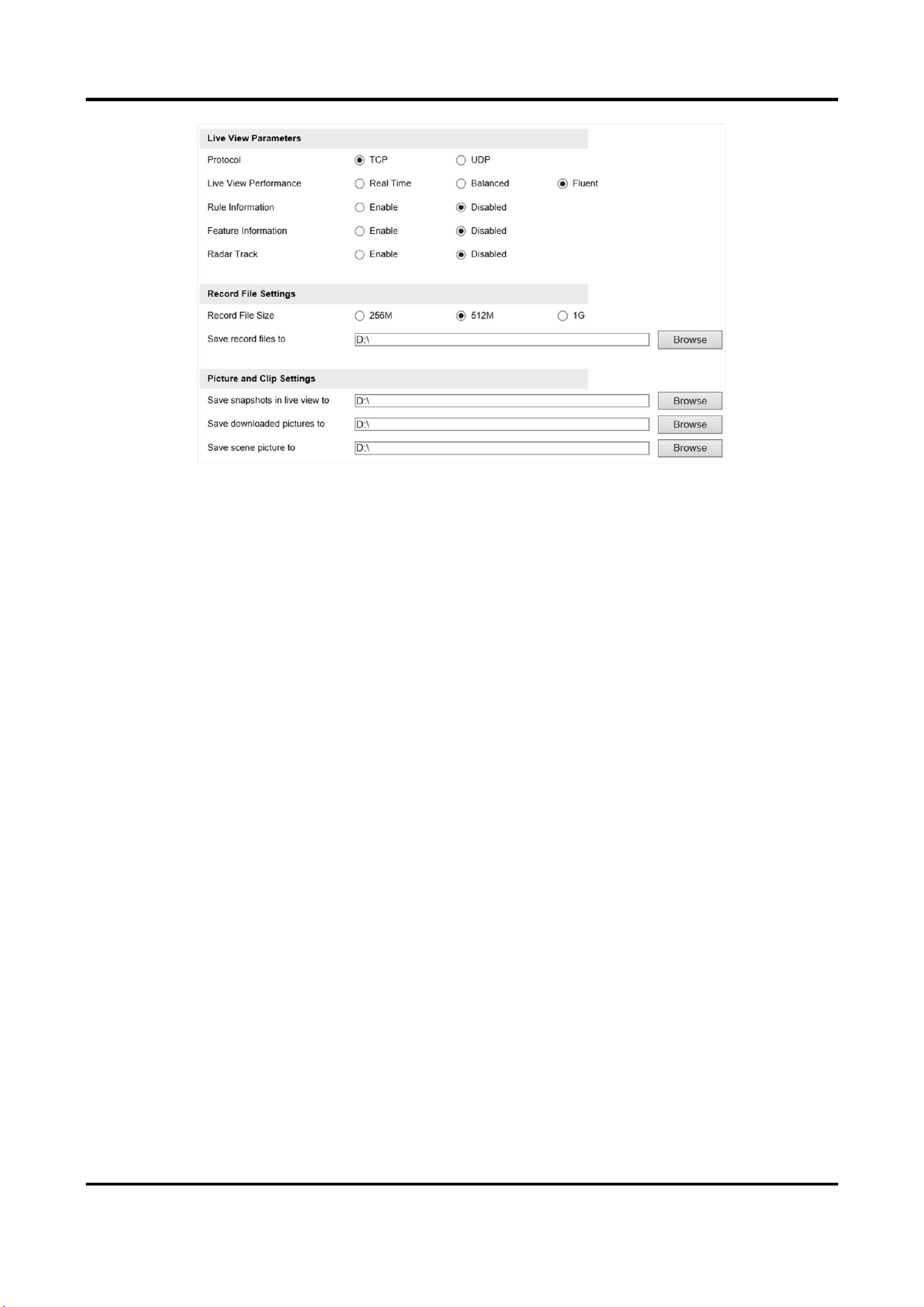
Figure 5-1 Local Configuration
Protocol
Select the network transmission protocol according to the actual needs.
TCP
Ensures complete delivery of streaming data and better video quality, yet the real-time
transmission will be affected.
UDP
Provides real-time audio and video streams.
Live View Performance
Real Time
The video is real-time, but the video fluency may be affected.
Balanced
Balanced mode considers both the real time and fluency of the video.
Fluent
When the network condition is good, the video is fluent.
Rule Information
If you enable the rule information, frames will be displayed on the live view interface when
there are vehicles passing.
Feature Information
If you enable the feature information, information of the lane, traffic flow, speed, etc. will be
displayed on the live view interface.
Record File Size

Radar-Assisted Traffic Camera User Manual
34
Select the packed size of the manually recorded video files. After the selection, the max. record
file size is the value you selected.
Save record files to
Set the saving path for the manually recorded video files.
Save snapshots in live view to
Set the saving path of the manually captured pictures in live view mode.
Save downloaded pictures to
Set the saving path for the downloaded pictures.
Save scene picture to
Set the saving path of the captured pictures in the Real-Time Status and Traffic Flow Statistics
interface.
Note
The parameters vary with different models. The actual device prevails.
Radar-Assisted Traffic Camera User Manual
35
Chapter 6 Record and Capture
6.1 Set Storage Path
6.1.1 Set Storage Card
If you want to store the files to the storage card, make sure you insert and format the storage card
in advance.
Before You Start
Insert the storage card to the device.
Steps
1. Go to Configuration → Device Configuration → Encoding and Storage → Storage Management.
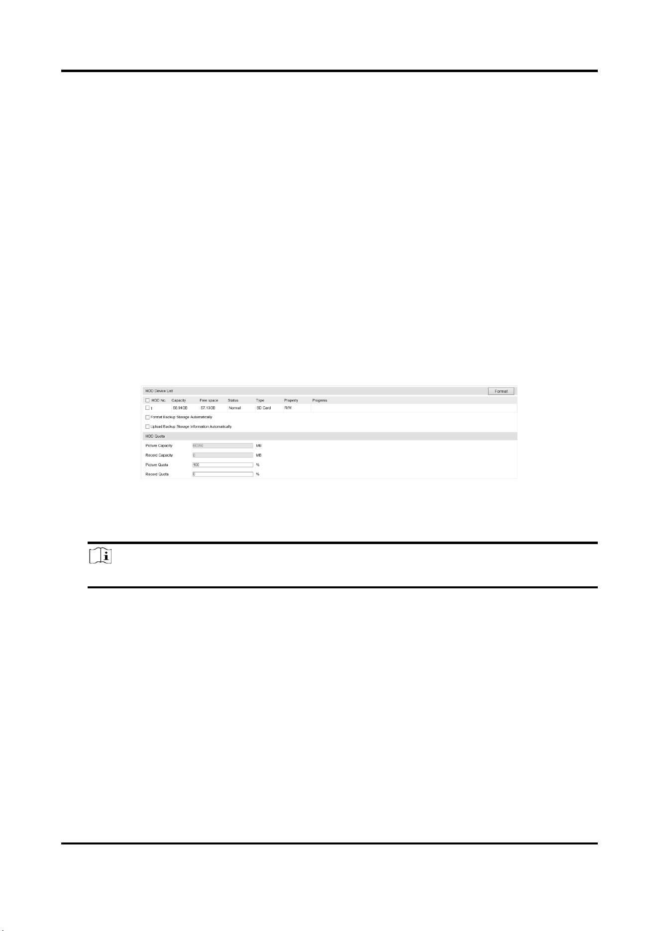
Figure 6-1 Set Storage Card
2. Format the storage card in two ways.
–
Check the storage card, and click Format to format it manually.
Note
For the newly installed storage card, you need to format it manually before using it normally.
–
If you want to format the storage card automatically when the card is abnormal, check
Format Backup Storage Automatically.
3. Optional: If the device has been connected to the platform, and you want to upload the storage
card information automatically, check Upload Backup Storage Information Automatically.
4. Click Save.
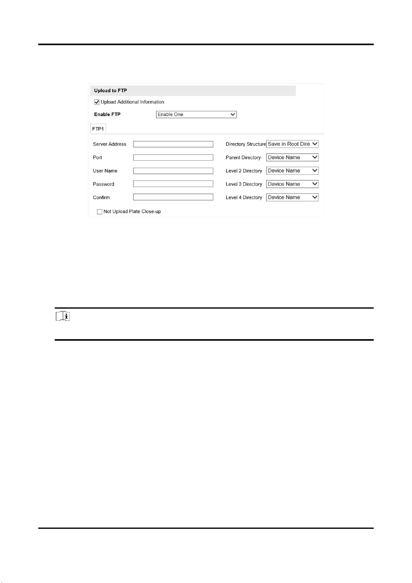
6.1.2 Set FTP
Set FTP parameters if you want to upload the captured pictures to the FTP server.
Before You Start
Set the FTP server, and ensure the device can communicate normally with the server.
Radar-Assisted Traffic Camera User Manual
36
Steps
1. Go to Configuration → Device Configuration → Encoding and Storage → FTP.
Figure 6-2 Set FTP
2. Optional: Check Upload Additional Information, and then the related information can be
attached when uploading.
3. Enable the FTP server.
4. Set FTP parameters.
1) Enter Server Address and Port.
2) Enter User Name and Password, and confirm the password.
3) Select Directory Structure.
Note
If multiple directories are needed, you can customize the directory name.
5. Optional: Check Not Upload Plate Close-up if the license plate close-up pictures are not needed
to upload.
6. Set the name rule and separator according to the actual needs.
7. Optional: Edit OSD information which can be uploaded to the FTP server with the pictures to
make it convenient to view and distinguish the data.
8. Click Save.
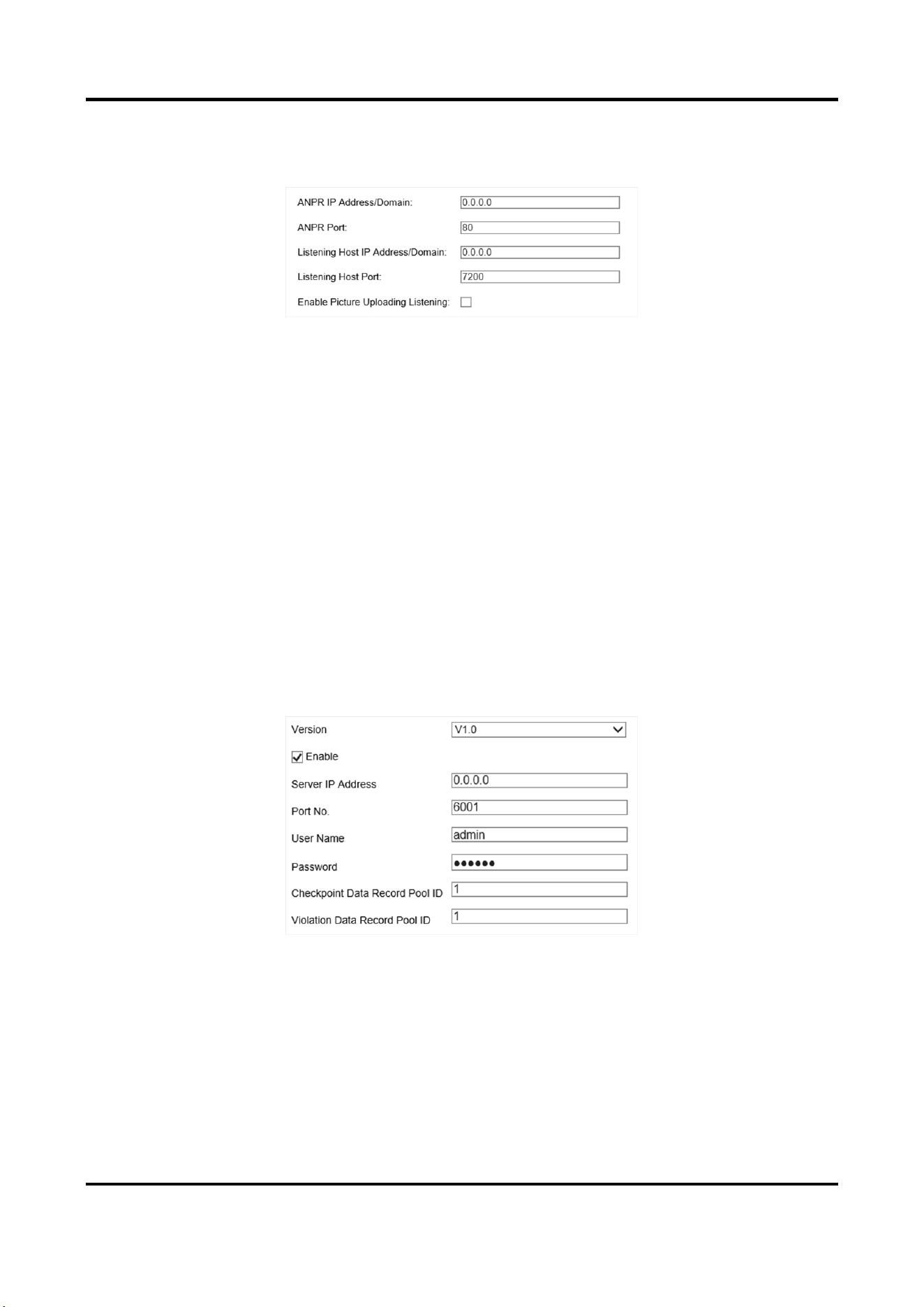
6.1.3 Set Listening Host
The listening host can be used to receive the uploaded information and pictures of the device
arming alarm.
Before You Start
The listening service has been enabled for the listening host, and the network communication with
the device is normal.
Radar-Assisted Traffic Camera User Manual
37
Steps
1. Go to Configuration → Device Configuration → System → Network Interface Parameters.
Figure 6-3 Set Listening Host
2. Set ANPR IP Address/Domain and ANPR Port if you need to upload the alarm information.
3. Set Listening Host IP Address/Domain and Listening Host Port, and check Enable Picture
Uploading Listening if you need to upload pictures.
4. Click Save.
6.1.4 Set Cloud Storage
Cloud storage is a kind of network storage. It can be used as the extended storage to save the
captured pictures.
Before You Start
●
Arrange the cloud storage server.
●
You have enabled level 1 arm in Real-Time Status and Traffic Flow Statistics.
Steps
1. Go to Configuration → Device Configuration → Encoding and Storage → Cloud Storage.
Figure 6-4 Set Cloud Storage
2. Select Version.
3. Set the server parameters.
1) Check Enable.
2) Enter Server IP Address and Port No.
3) Set other parameters.

Radar-Assisted Traffic Camera User Manual
38
Note
The interface varies with the version that you select.
4. Click Save.
6.2 Set Quota
Set the video and picture ratio in the storage.
Before You Start
Install the storage card.
Steps
1. Go to Configuration → Device Configuration → Encoding and Storage → Storage Management.
2. Set Picture Quota and Record Quota according to the actual needs.
Note
The percentage sum of the picture and record quota ratio should be 100%.
3. Click Save.
What to do next
Format the storage card after the settings.
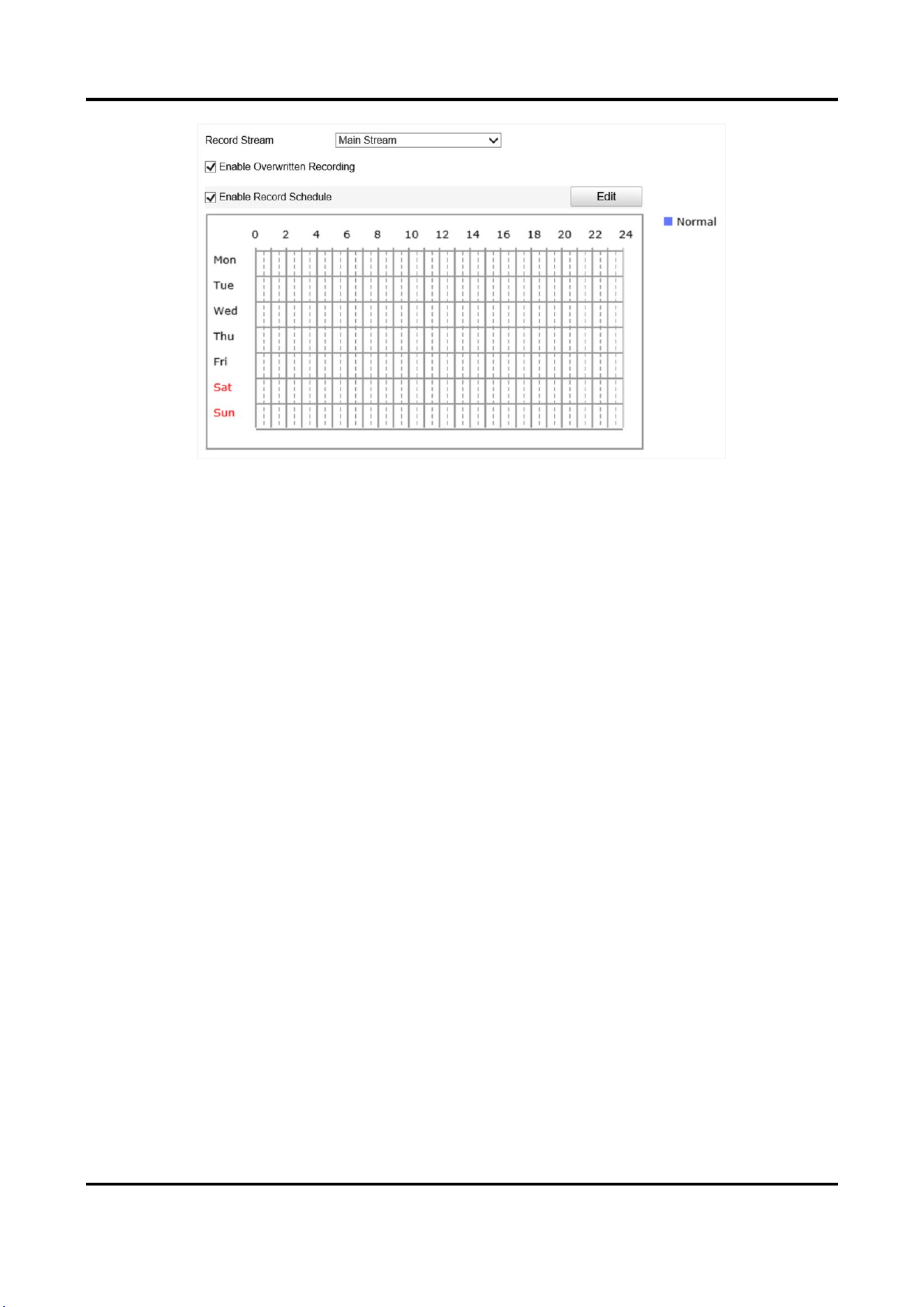
6.3 Set Record Schedule
Set record schedule to record video automatically during configured time periods.
Before You Start
Install the storage card, and the video quota ratio is not 0.
Steps
1. Go to Configuration → Device Configuration → Encoding and Storage → Record Schedule.
Radar-Assisted Traffic Camera User Manual
39
Figure 6-5 Set Record Schedule
2. Optional: Check Enable Overwritten Recording.
When the storage is full, the earliest videos will be overwritten.
3. Check Enable Record Schedule.
4. Click Edit to edit the record schedule.
1) Select Customize.
2) Set the start time and end time.
3) Optional: Select the other days and click Copy to copy the settings to other days.
4) Click OK.
5. Click Save.

Radar-Assisted Traffic Camera User Manual
40
Chapter 7 Encoding and Display
7.1 Set Video Encoding Parameters
Set video encoding parameters to adjust the live view and recording effect.
●
When the network signal is good and the speed is fast, you can set high resolution and bitrate to
raise the image quality.
●
When the network signal is bad and the speed is slow, you can set low resolution, bitrate, and
frame rate to guarantee the image fluency.
●
When the network signal is bad, but the resolution should be guaranteed, you can set low
bitrate and frame rate to guarantee the image fluency.
●
Main stream stands for the best stream performance the device supports. It usually offers the
best resolution and frame rate the device can do. But high resolution and frame rate usually
means larger storage space and higher bandwidth requirements in transmission. Sub-stream
usually offers comparatively low resolution options, which consumes less bandwidth and
storage space. Third stream is offered for customized usage.
Steps
1. Go to Configuration → Device Configuration → Encoding and Storage → Video Encoding.
2. Set the parameters for different streams.
Stream Type
Only video stream is available.
Bitrate
Select relatively large bitrate if you need good image quality and effect, but more storage
spaces will be consumed. Select relatively small bitrate if storage requirement is in priority.
Frame Rate
It is to describe the frequency at which the video stream is updated and it is measured by
frames per second (fps). A higher frame rate is advantageous when there is movement in the
video stream, as it maintains image quality throughout.
Resolution
The higher the resolution is, the clearer the image will be. Meanwhile, the network
bandwidth requirement is higher.
SVC
Scalable Video Coding (SVC) is an extension of the H.264/AVC and H.265 standard. Enable the
function and the device will automatically extract frames from the original video when the
network bandwidth is insufficient.
Bitrate Type
Radar-Assisted Traffic Camera User Manual
41
Select the bitrate type to constant or variable.
Image Quality
When bitrate type is variable, 6 levels of image quality are selectable. The higher the image
quality is, the higher requirements of the network bandwidth.
Profile
When you select H.264 or H.265 as video encoding, you can set the profile. Selectable profiles
vary according to device models.
I Frame Interval
It refers to the number of frames between two key frames. The larger the I frame interval is,
the smaller the stream fluctuation is, but the image quality is not that good.
Video Encoding
The device supports multiple video encoding types, such as H.264, H.265, and MJPEG.
Supported encoding types for different stream types may differ. H.265 is a new encoding
technology. Compared with H.264, it reduces the transmission bitrate under the same
resolution, frame rate, and image quality.
3. Click Save.
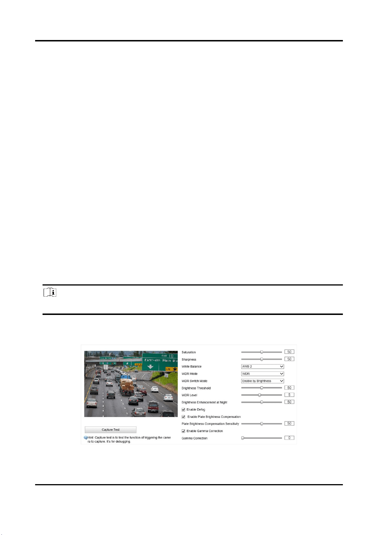
7.2 Set Image Parameters
You can adjust the image parameters to get clear image.
Steps
Note
The supported parameters may vary with different models. The actual device prevails.
1. Go to Configuration → Device Configuration → Image Parameters → General
Parameters/Configuration → Device Configuration → Image Parameters → Video.
Figure 7-1 Set General Parameters
Radar-Assisted Traffic Camera User Manual
42
Figure 7-2 Set Video Image Parameters
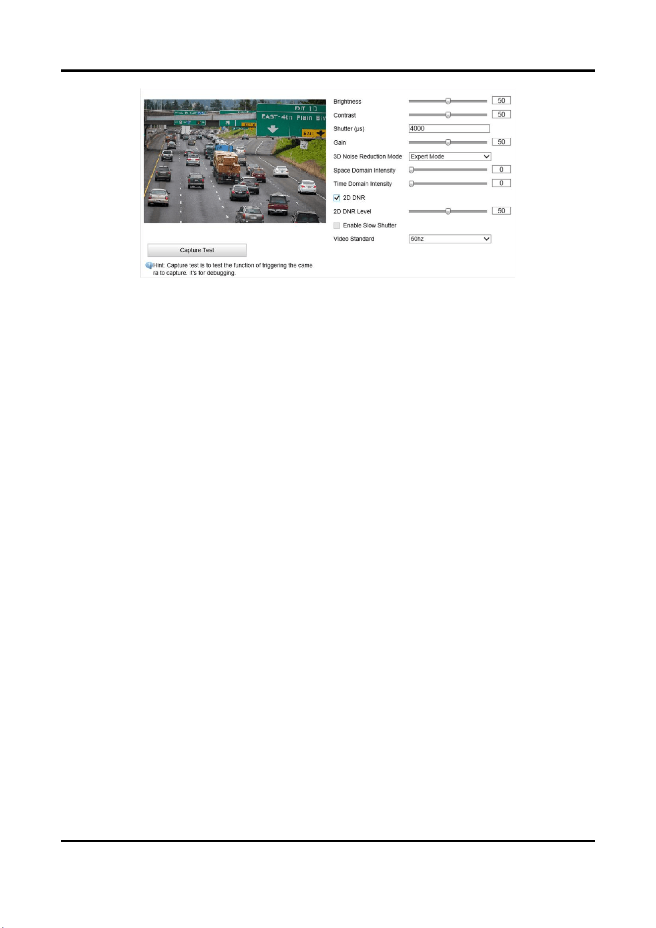
2. Adjust the parameters.
Saturation
It refers to the colorfulness of the image color.
Sharpness
It refers to the edge contrast of the image.
White Balance
It is the white rendition function of the device used to adjust the color temperature according
to the environment.
WDR Mode
Wide Dynamic Range (WDR) can be used when there is a high contrast of the bright area and
the dark area of the scene.
Select WDR Switch Mode and set corresponding parameters according to your needs.
Enable
Set WDR Level. The higher the level is, the higher the WDR strength is.
Enable by Time
Enable WDR according to the time.
Enable by Brightness
Set Brightness Threshold. When the brightness reaches the threshold, WDR will be
enabled.
Brightness Enhancement at Night
The scene brightness will be enhanced at night automatically.
Enable Defog
Enable defog to get a clear image in foggy days.
Enable Plate Brightness Compensation

Radar-Assisted Traffic Camera User Manual
43
Check it. The plate brightness compensation can be realized, and various light supplement
conditions can be adapted via setting license plate expectant brightness and supplement light
correction coefficient. The higher the sensitivity is, the easier this function can be enabled.
Enable Gamma Correction
The higher the gamma correction value is, the stronger the correction strength is.
Brightness
It refers to the max. brightness of the image.
Contrast
It refers to the contrast of the image. Set it to adjust the levels and permeability of the image.
Shutter
If the shutter speed is quick, the details of the moving objects can be displayed better. If the
shutter speed is slow, the outline of the moving objects will be fuzzy and trailing will appear.
Gain
It refers to the upper limit value of limiting image signal amplification. It is recommended to
set a high gain if the illumination is not enough, and set a low gain if the illumination is
enough.
3D Noise Reduction Mode
Digital Noise Reduction (DNR) reduces the noise in the video stream.
In Normal Mode, the higher the Noise Reduction Level is, the stronger the noise will be
reduced. But if it is too high, the image may become fuzzy.
In Expert Mode, set Space Domain Intensity and Time Domain Intensity. If the space domain
intensity is too high, the outline of the image may become fuzzy and the details may lose. If
the time domain intensity is too high, trailing may appear.
2D DNR
The higher the 2D DNR Level is, the stronger the noise will be reduced. But if it is too high,
the image may become fuzzy.
Enable Slow Shutter
You can enable slow shutter to increase the exposure time and raise the photosensitivity.
Then the image brightness can be raised in low illumination conditions.
Video Standard
Select the video standard according to the actual power supply frequency.

Radar-Assisted Traffic Camera User Manual
44
7.3 Set ICR
ICR adopts mechanical IR filter to filter IR in the day to guarantee the image effect, and to remove
the IR filter at night to guarantee full-spectrum rays can get through the device.
Steps
1. Go to Configuration → Device Configuration → Image Parameters → ICR.
2. Select ICR Mode.
Auto-Switch
Switches to ICR mode automatically at night or in dark light
conditions.
Manual Switch
Select Day/Night Mode to switch to the day or night manually.
Scheduled Mode
Set day/night mode, start time, and end time to switch to ICR mode
only during the set time period.
No Switch
Disable the ICR mode.
3. Click Save.
7.4 Set ROI
ROI (Region of Interest) encoding helps to assign more encoding resources to the region of interest,
thus to increase the quality of the ROI whereas the background information is less focused.
Before You Start
Please check the video encoding type. ROI is supported when the video encoding type is H.264 or
H.265.
Steps
1. Go to Configuration → Device Configuration → Encoding and Storage → ROI.
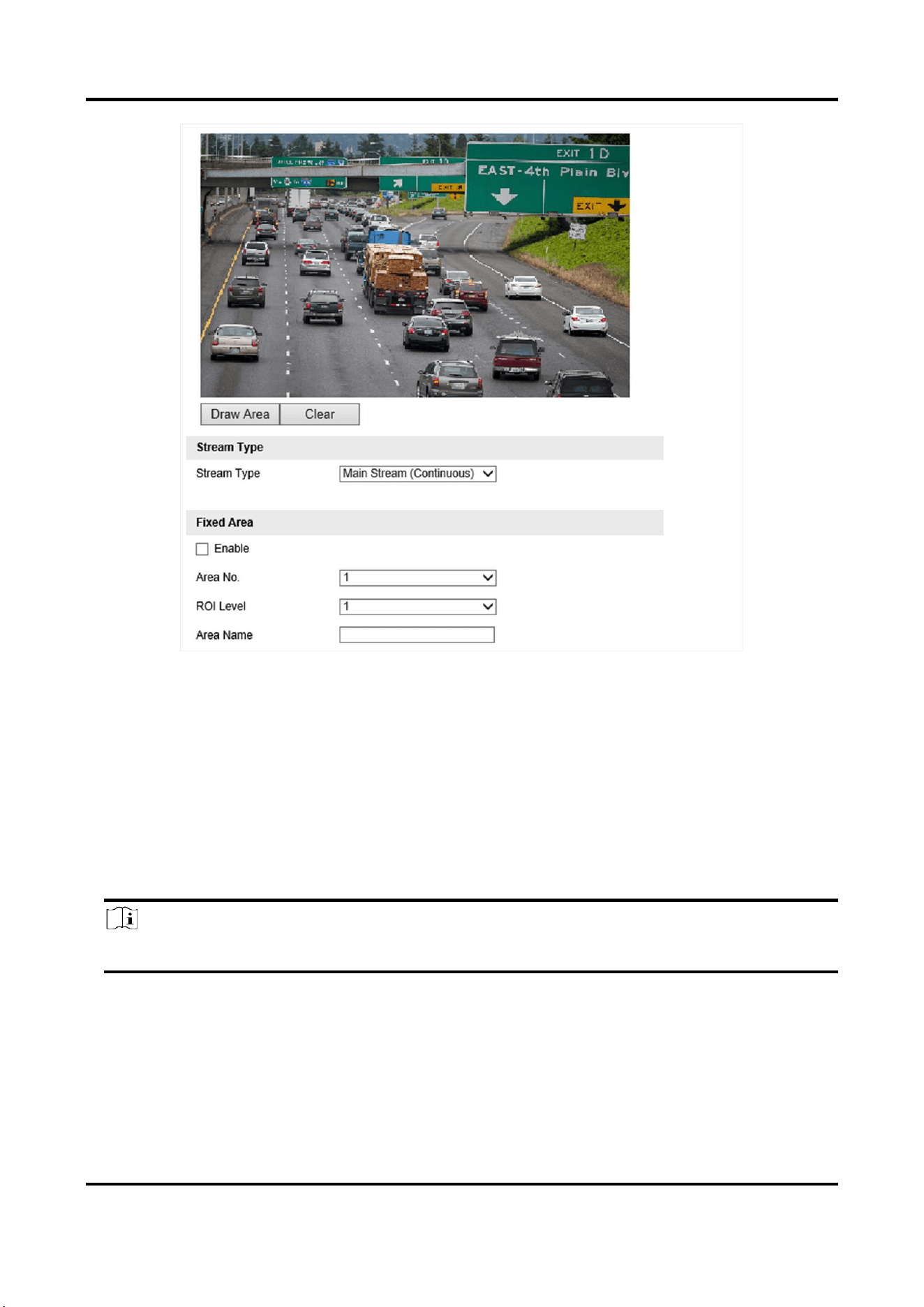
Radar-Assisted Traffic Camera User Manual
45
Figure 7-3 Set ROI
2. Select Stream Type.
3. Set ROI region.
1) Check Enable.
2) Select Area No.
3) Click Draw Area.
4) Drag the mouse on the live view image to draw a fixed area.
5) Select the fixed area that needs to be adjusted and drag the mouse to adjust its position.
6) Click Stop Drawing.
4. Select Area No. and ROI Level and enter Area Name.
Note
The higher the ROI level is, the clearer the image of the detected area is.
5. Click Save.
6. Optional: Select other area codes and repeat the steps above if you need to draw multiple fixed
areas.
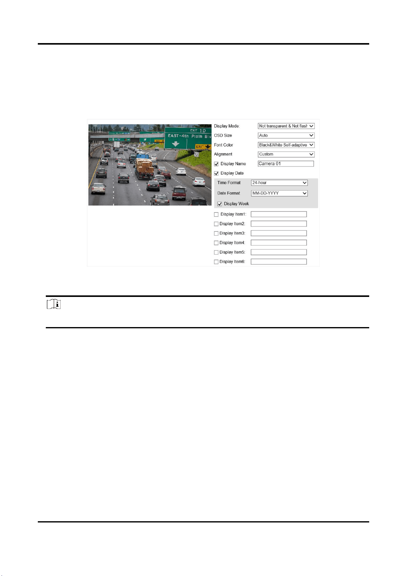
Radar-Assisted Traffic Camera User Manual
46
7.5 Set OSD
You can customize OSD information on the live view.
Steps
1. Go to Configuration → Device Configuration → Text Overlay → OSD Settings.
Figure 7-4 Set OSD
2. Set the display mode, size, color, etc.
Note
The supported functions vary with different models. The actual device prevails.
3. Set the display content.
1) Check Display Name and enter the name.
2) Check Display Date, and set the time and date format.
3) Check Display Week.
4. Optional: Check the display item(s) and enter information in the text field(s).
5. Drag the red frames on the live view image to adjust the OSD positions.
6. Click Save.
Result
The set OSD will be displayed in live view image and recorded videos.
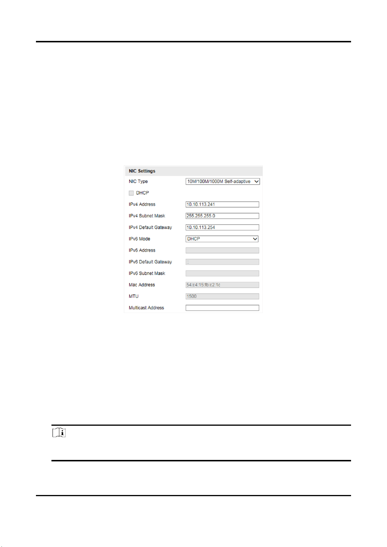
Radar-Assisted Traffic Camera User Manual
47
Chapter 8 Network Configuration
8.1 Set IP Address
IP address must be properly configured before you operate the device over network. IPv4 and IPv6
are both supported. Both versions can be configured simultaneously without conflicting to each
other.
Go to Configuration → Device Configuration → System → Network Interface Parameters.
Figure 8-1 Set IP Address
NIC Type
Select a NIC (Network Interface Card) type according to your network condition.
IPv4
Two IPv4 modes are available.
DHCP
The device automatically gets the IPv4 parameters from the network if you check DHCP. The
device IP address is changed after enabling the function. You can use SADP to get the device
IP address.
Note
The network that the device is connected to should support DHCP (Dynamic Host
Configuration Protocol).

Radar-Assisted Traffic Camera User Manual
48
Manual
You can set the device IPv4 parameters manually. Enter IPv4 Address, IPv4 Subnet Mask, and
IPv4 Default Gateway.
IPv6
Three IPv6 modes are available.
Route Advertisement
The IPv6 address is generated by combining the route advertisement and the device Mac
address.
Note
Route advertisement mode requires the support from the router that the device is connected
to.
DHCP
The IPv6 address is assigned by the server, router, or gateway.
Manual
Enter IPv6 Address, IPv6 Subnet Mask, and IPv6 Default Gateway. Consult the network
administrator for required information.
MTU
It stands for maximum transmission unit. It is the size of the largest protocol data unit that can
be communicated in a single network layer transaction.
The valid value range of MTU is 1280 to 1500.
Multicast
Multicast is group communication where data transmission is addressed to a group of
destination devices simultaneously. After setting the IP address of the multicast host, you can
send the source data efficiently to multiple receivers.
DNS
It stands for domain name server. It is required if you need to visit the device with domain name.
And it is also required for some applications (e.g., sending email). Set Preferred DNS Server
properly if needed.
8.2 Connect to ISUP Platform
ISUP (EHome) is a platform access protocol. The device can be remotely accessed via this platform.
Before You Start
●
Create the device ID on ISUP platform.
●
Ensure the device can communicate with the platform normally.
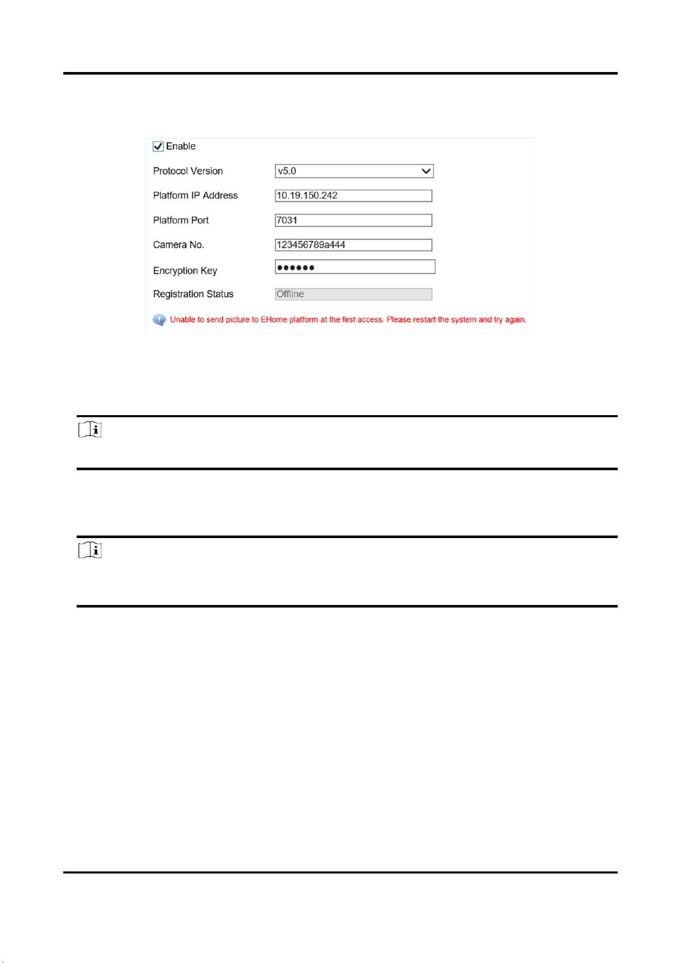
Radar-Assisted Traffic Camera User Manual
49
Steps
1. Go to Configuration → Device Configuration → System → ISUP Protocol.
Figure 8-2 Connect to ISUP Platform
2. Check Enable.
3. Select Protocol Version.
4. Enter Platform IP Address, Platform Port, and Camera No.
Note
The camera No. should be the same with the added one on the ISUP platform.
5. Optional: Enter Encryption Key if you select v5.0.
6. Click Save.
7. Optional: View Registration Status.
Note
When the registration status shows online, you can add or manage the device via the platform
software. Refer to its corresponding manual for details.
8.3 Set DDNS
You can use the Dynamic DNS (DDNS) for network access. The dynamic IP address of the device
can be mapped to a domain name resolution server to realize the network access via domain
name.
Before You Start
●
Register the domain name on the DDNS server.
●
Set the LAN IP address, subnet mask, gateway, and DNS server parameters. Refer to "Set IP
Address" for details.
●
Complete port mapping. The default port is 80, 8000, and 554.
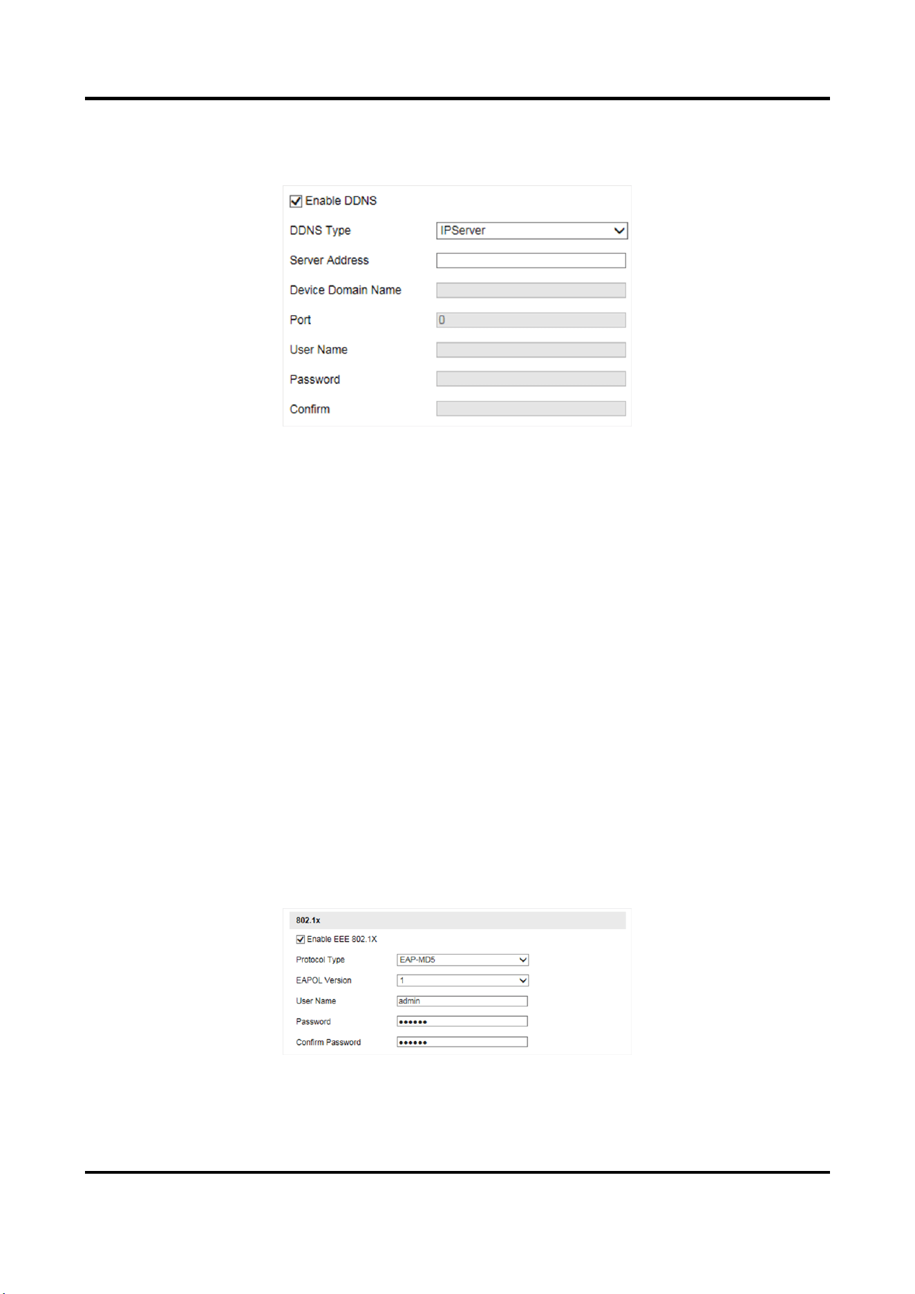
Radar-Assisted Traffic Camera User Manual
50
Steps
1. Go to Configuration → Device Configuration → System → DDNS.
Figure 8-3 Set DDNS
2. Check Enable DDNS.
3. Enter the server address and other information.
4. Click Save.
5. Access the device.
By Browsers
Enter the domain name in the browser address bar to access the
device.
By Client Software
Add domain name to the client software. Refer to the client software
manual for specific adding methods.
8.4 Set IEEE 802.1X
IEEE 802.1x is a port-based network access control. It enhances the security level of the
LAN/WLAN. When devices connect to the network with IEEE 802.1x standard, the authentication is
needed.
Steps
1. Go to Configuration → Device Configuration → System → 802.1x.
Figure 8-4 Set IEEE 802.1X
2. Check Enable EEE 802.1X.

Radar-Assisted Traffic Camera User Manual
51
3. Select Protocol Type and EAPOL Version.
EAP-MD5
If you use EAP-MD5, the authentication server must be configured. Register a user name and
password for 802.1X in the server in advance. Enter the user name and password for
authentication.
EAPOL Version
The EAPOL version must be identical with that of the router or the switch.
4. Enter User Name and Password registered in the server.
5. Confirm the password.
6. Click Save.
8.5 Set Image and Video Library
Set the interaction parameters of the device consistent with those of the image and video library
platform via the image and video library (1400) protocol, and register the device on the platform.
When the device generates alarm signals, the alarm information will be sent to the platform.
Steps
Note
The function varies with different models. The actual device prevails.
1. Go to Configuration → Device Configuration → System → Image and Video Library.
2. Check Enable.
3. Set the parameters such as the device ID, user name, password, etc.
Note
The parameters should be consistent with those on the image and video library platform.
4. Set other parameters.
Heartbeat Cycle
The connection time between the device and the image and video library platform.
Max. Times of Heartbeat Timeout
The max. times of heartbeat timeout when the device connects to the image and video
library platform.
5. View Registration Status.
6. Set Camera ID of the channel.
7. Click Save.
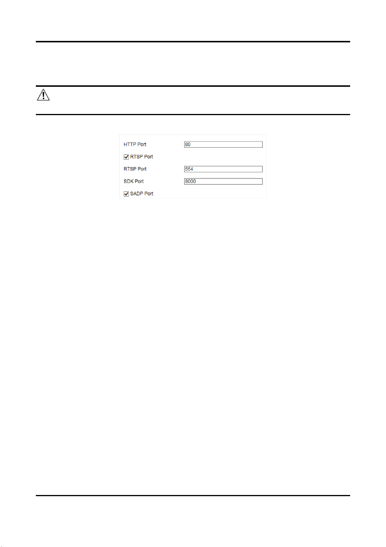
Radar-Assisted Traffic Camera User Manual
52
8.6 Set Port
The device port can be modified when the device cannot access the network due to port conflicts.
Caution
Do not modify the default port parameters at will, otherwise the device may be inaccessible.
Go to Configuration → Device Configuration → System → Port for port settings.
Figure 8-5 Set Port
HTTP Port
It refers to the port through which the browser accesses the device. For example, when the
HTTP Port is modified to 81, you need to enter http://192.168.1.64:81 in the browser for login.
RTSP Port
It refers to the port of real-time streaming protocol.
SDK Port
It refers to the port through which the client adds the device.
SADP Port
It refers to the port through which the SADP software searches the device.
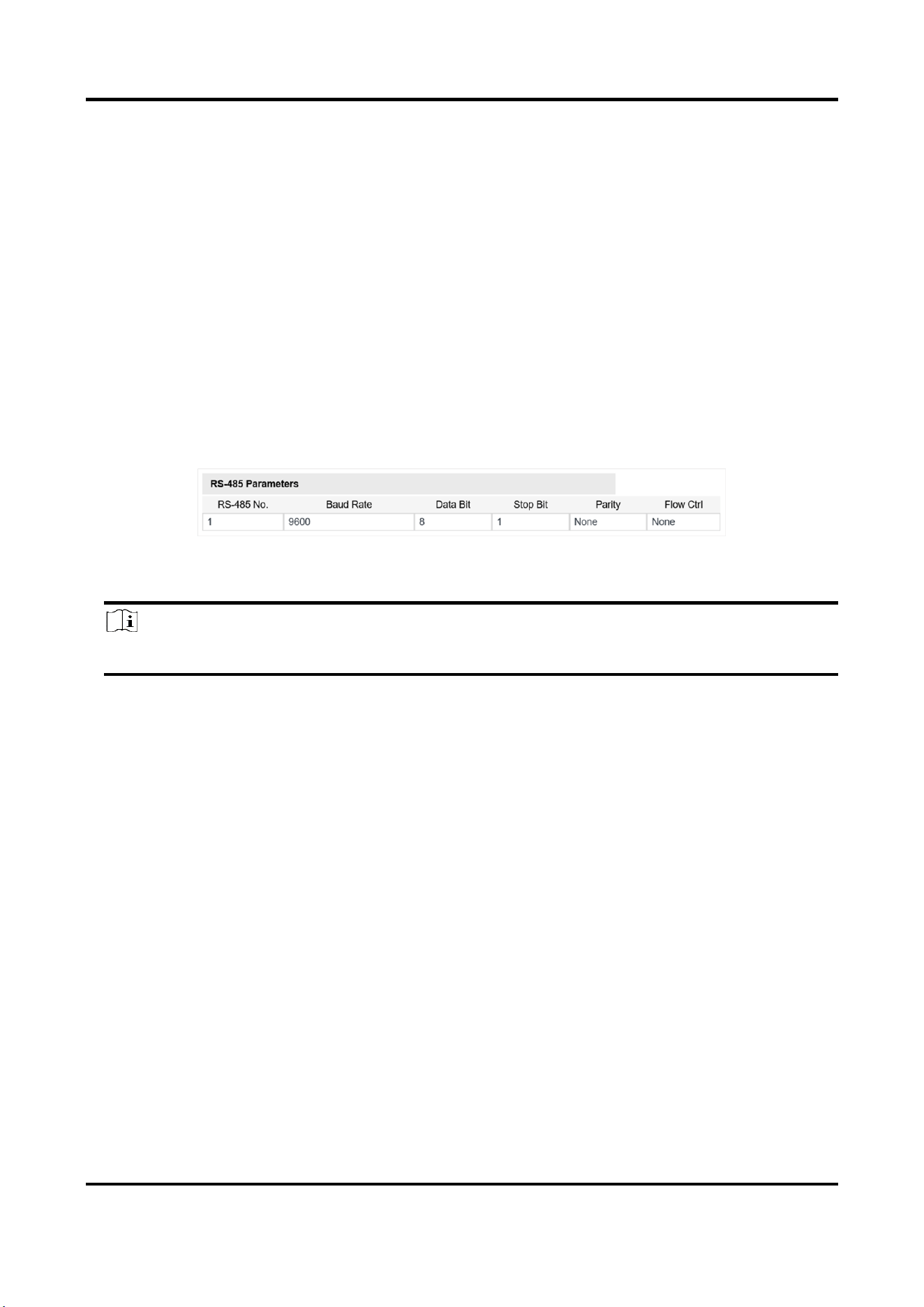
Radar-Assisted Traffic Camera User Manual
53
Chapter 9 Serial Port Configuration
9.1 Set RS-485
Set RS-485 parameters if the device has been connected to a vehicle detector or other RS-485
devices.
Before You Start
The corresponding device has been connected via the RS-485 serial port.
Steps
1. Go to Configuration → Device Configuration → System → Serial Port Parameters.
Figure 9-1 Set RS-485
2. Set Baud Rate, Data Bit, Stop Bit, etc.
Note
The parameters should be same with those of the connected device.
3. Click Save.
9.2 Set RS-232
Set RS-232 parameters if you need to debug the device via RS-232 serial port, or peripheral
devices have been connected.
Before You Start
The corresponding device has been connected via the RS-232 serial port.
Steps
1. Go to Configuration → Device Configuration → System → Serial Port Parameters.
2. Click Advanced Settings.
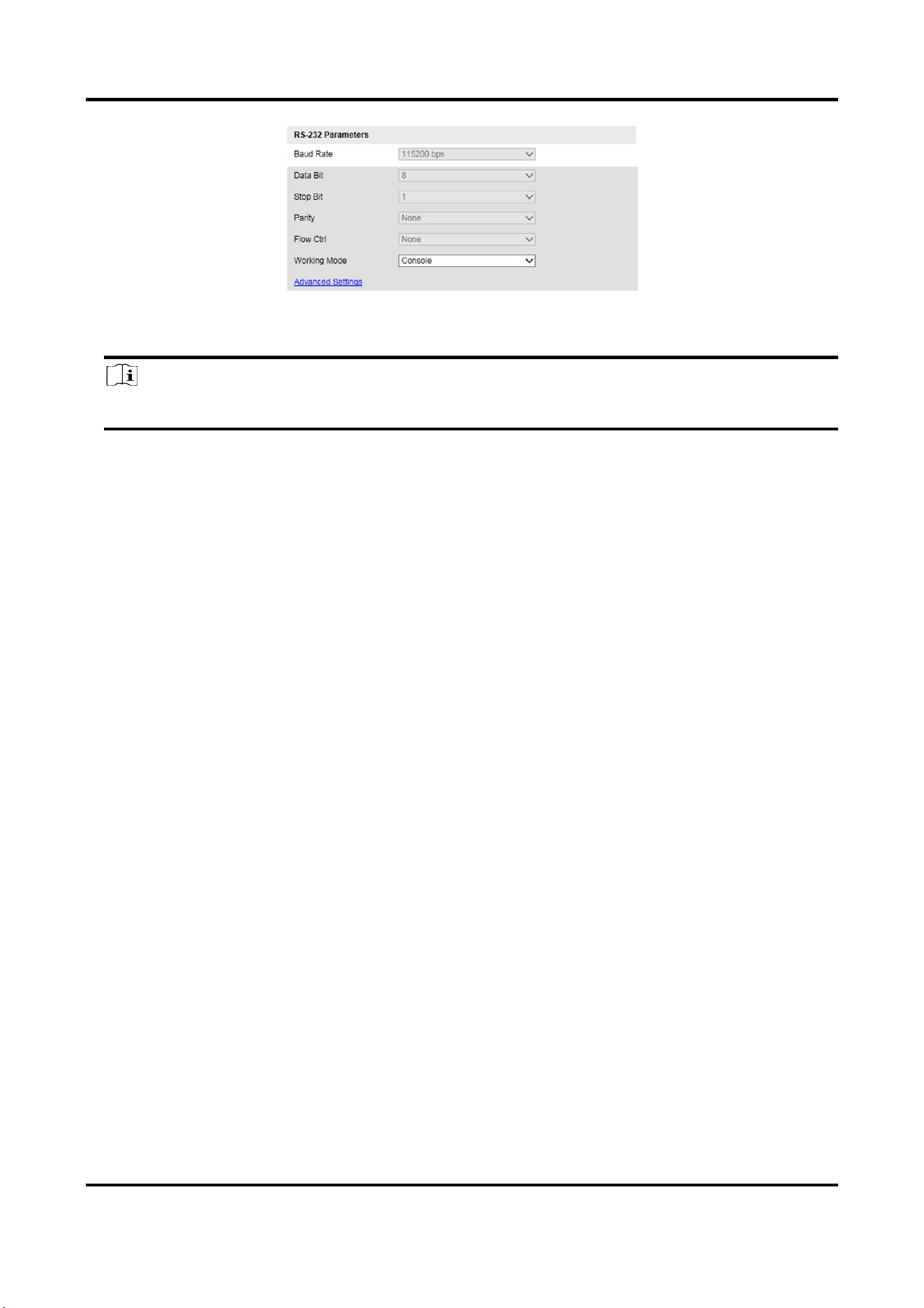
Radar-Assisted Traffic Camera User Manual
54
Figure 9-2 Set RS-232
3. Set Baud Rate, Data Bit, Stop Bit, etc.
Note
The parameters should be same with those of the connected device.
4. Select Working Mode.
Console
Select it when you need to debug the device via RS-232 serial port.
Transparent Channel
Select it, and the network command can be transmitted to RS-232 control command via the
RS-232 serial port.
Narrow Band Transmission
Reserved.
5. Click Save.
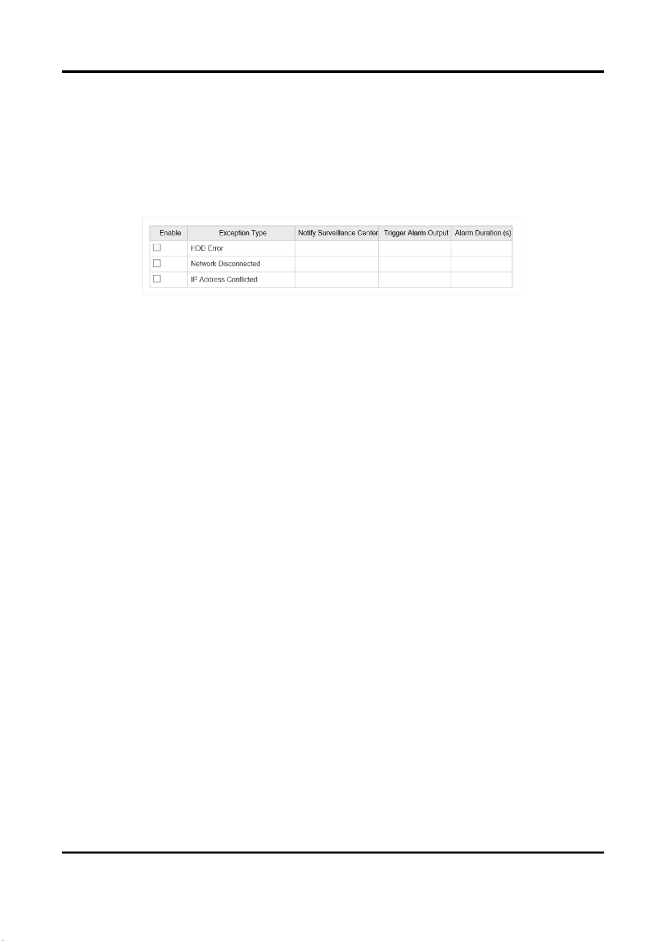
Radar-Assisted Traffic Camera User Manual
55
Chapter 10 Exception Alarm
Set exception alarm when the network is disconnected, the IP address is conflicted, etc.
Steps
1. Go to Configuration → Device Configuration → Events → Exception Event.
Figure 10-1 Set Exception Alarm
2. Select the exception type(s) and the linkage method.
3. Click Save.

Radar-Assisted Traffic Camera User Manual
56
Chapter 11 Safety Management
11.1 Manage User
The administrator can add, modify, or delete other accounts, and grant different permissions to
different user levels.
Steps
1. Go to Configuration → Device Configuration → User Management.
2. Add a user.
1) Click Add.
2) Enter User Name and select Level.
3) Enter Admin Password, Password, and confirm the password.
Caution
To increase security of using the device on the network, please change the password of your
account regularly. Changing the password every 3 months is recommended. If the device is
used in high-risk environment, it is recommended that the password should be changed every
month or week.
4) Assign remote permission to users based on needs.
User
Users can be assigned permission of viewing live video and changing their own passwords,
but no permission for other operations.
Operator
Operators can be assigned all permission except for operations on the administrator and
creating accounts.
5) Click OK.
Note
The administrator can add up to 31 user accounts.
3. You can do the following operations.
–
Select a user and click Modify to change the password and permission.
–
Select a user and click Delete to delete the user.

Radar-Assisted Traffic Camera User Manual
57
11.2 Enable User Lock
To raise the data security, you are recommended to lock the current IP address.
Steps
1. Go to Configuration → Device Configuration → System → Service.
2. Check Enable User Lock.
3. Click Save.
Result
When the times you entered incorrect passwords have reached the limit, the current IP address
will be locked automatically.
11.3 Set HTTPS
11.3.1 Create and Install Self-signed Certificate
HTTPS is a network protocol that enables encrypted transmission and identity authentication,
which improves the security of remote access.
Steps
1. Go to Configuration → Device Configuration → System → HTTPS.
2. Select Create Self-Signed Certificate.
3. Click Create.
4. Follow the prompt to enter Country/Region, IP Address, Valid Date (Day), and other
parameters.
5. Click OK.
Result
The device will install the self-signed certificate by default.
11.3.2 Install Authorized Certificate
If the demand for external access security is high, you can create and install authorized certificate
via HTTPS protocol to ensure the data transmission security.
Steps
1. Go to Configuration → Device Configuration → System → HTTPS.
2. Select Create the certificate request first and continue the installation.
3. Click Create.
4. Follow the prompt to enter Country/Region, IP Address, and other parameters.
5. Click Download to download the certificate request and submit it to the trusted authority for
signature.

Radar-Assisted Traffic Camera User Manual
58
6. Import certificate to the device.
–
Select Signed certificate is available. Start the installation directly. Click Browse and Install
to import the certificate to the device.
–
Select Create the certificate request first and continue the installation. Click Browse and
Install to import the certificate to the device.
7. Click Save.
11.4 Set SSH
To raise network security, disable SSH service. The configuration is only used to debug the device
for the professionals.
Steps
1. Go to Configuration → Device Configuration → System → Service.
2. Uncheck Enable SSH Service.
3. Click Save.

Radar-Assisted Traffic Camera User Manual
59
Chapter 12 Maintenance
12.1 View Device Information
Basic Information and Algorithms Library Version
Go to Configuration → Device Configuration → System → Device Information to view the basic
information and algorithms library version of the device.
You can edit Device Name and Device No. The device No. is used to control the device. It is
recommended to reserve the default value.
Device Status
Go to Configuration → Device Status to view the device status, Wi-Fi status, Wi-Fi AP status, etc.
12.2 Log
12.2.1 Enable System Log Service
The security audit logs refer to the security operation logs. You can search and analyze the security
log files of the device so as to find out the illegal intrusion and troubleshoot the security events.
Security audit logs can be saved on device internal storage. The log will be saved every half hour
after device booting. Due to limited storage space, you are recommended to save the logs on a log
server.
Steps
1. Go to Configuration → Device Configuration → System → Service.
2. Check Enable Syslog Service.
3. Enter IP Address and Port of the log server.
4. Click Save.
Result
The device will upload the security audit logs to the log server regularly.
12.2.2 Search Log
Log helps to locate and troubleshoot problems.
Steps
1. Click Log.
2. Set search conditions.

Radar-Assisted Traffic Camera User Manual
60
3. Click Search.
The matched log files will be displayed on the log list.
4. Optional: Click Save Log to save the log files to your computer.
12.3 Upgrade
Upgrade the system when you need to update the device version.
Before You Start
Prepare the upgrade file.
Steps
1. Go to Configuration → Device Configuration → System Maintenance → Upgrade.
2. Click Browse to select the upgrade file.
3. Click Upgrade.
4. Click OK in the popup window.
Note
The upgrade process will take 1 to 10 minutes. Do not cut off the power supply.
Result
The device will reboot automatically after upgrade.
12.4 Reboot
When the device needs to be rebooted, reboot it via the software instead of cutting off the power
directly.
Steps
1. Go to Configuration → Device Configuration → System Maintenance → Reboot.
2. Click Reboot.
3. Click OK to reboot the device.
12.5 Restore Parameters
When the device is abnormal caused by the incorrect set parameters, you can restore the
parameters.
Steps
1. Go to Configuration → Device Configuration → System Maintenance → Default.
2. Select the restoration mode.
–
Click Restore to restore the parameters except the IP parameters and user parameters to the

Radar-Assisted Traffic Camera User Manual
61
default settings.
–
Click Restore Factory Settings to restore all the parameters to the factory settings.
3. Click OK.
12.6 Synchronize Time
Synchronize the device time when it is inconsistent with the actual time.
Steps
1. Go to Configuration → Device Configuration → System → Time Settings.
2. Select Time Zone.
3. Select Time Sync. Mode.
NTP Time Sync.
Select it to synchronize the device time with that of the NTP server. Set Server Address, NTP
Port, and Interval. Click NTP Test to test if the connection between the device and the server
is normal.
Manual Time Sync.
Select it to synchronize the device time with that of the computer. Set time manually, or
check Sync. with computer time.
SDK
If the remote host has been set for the device, select it to synchronize time via the remote
host.
ONVIF
Select it to synchronize time via the third-party device.
No
Select it to disable time synchronization.
All
Select it, and you can select any mode above.
Note
The time synchronization modes vary with different models. The actual device prevails.
4. Click Save.

Radar-Assisted Traffic Camera User Manual
62
12.7 Set DST
If the region where the device is located adopts Daylight Saving Time (DST), you can set this
function.
Steps
1. Go to Configuration → Device Configuration → System → DST.
2. Check Enable DST.
3. Set Start Time, End Time, and DST Bias.
4. Click Save.
12.8 Debug
Note
The debug configurations below are only provided to debug the device by the professionals.
12.8.1 Enable Information Overlay
You can overlay the algorithm POS information and positioning frames on the captured pictures or
playback images.
Steps
1. Go to Configuration → Device Configuration → Advanced Settings → System Service.
2. Check the debug information according to your needs.
Enable Algorithm POS Information Debug
The algorithm POS information will be overlaid on the playback image when you play back
the video with the dedicated tool.
Enable Positioning Frame Debug
The positioning frames of vehicle bodies and license plates will be overlaid on the captured
pictures.
3. Click Save.
12.8.2 Set Capture Filtering
Set the capture filtering information. The filtered conditions will not be captured.
Steps
1. Go to Configuration → Device Configuration → Advanced Settings → Vehicle Capture and
Recognition Service.
2. Check the conditions to be filtered.

Radar-Assisted Traffic Camera User Manual
63
Not Capture No Plate Vehicle
The vehicles without license plates will not be captured.
Filter Checkpoint Capture of Same Vehicle
It is used to debug the device with the same vehicle. When the same vehicle is triggered
many times during a short period in the scene, the checkpoint pictures of the vehicle will not
be captured.
Note
The supported filtering information varies with different models. The actual device prevails.
3. Optional: Set the custom lane No. to upload.
1) Check Enable Custom Lane No.
2) Enter the lane No. to upload.
4. Click Save.
12.8.3 Set Image Format
You can enable smartJPEG which can save the storage space without influencing the resolution.
Steps
1. Go to Configuration → Device Configuration → Advanced Settings → Image Service.
2. Check smartJPEG.
3. Click Save.
12.9 Export Parameters
You can export the parameters of one device, and import them to another device to set the two
devices with the same parameters.
Steps
1. Go to Configuration → Device Configuration → System Maintenance → Export Parameters.
2. Click Export Parameters.
3. Set a password, and click OK.
Note
The password is used for importing the configuration file of the current device to other devices.
4. Select the saving path, and enter the file name.
5. Click Save.

Radar-Assisted Traffic Camera User Manual
64
12.10 Import Configuration File
Import the configuration file of another device to the current device to set the same parameters.
Before You Start
Save the configuration file to the computer.
Steps
Caution
Importing configuration file is only available to the devices of the same model and same
version.
1. Go to Configuration → Device Configuration → System Maintenance → Import Config. File.
2. Select Importing Method.
Note
If you select Import Part, check the parameters to be imported.
3. Click Browse to select the configuration file.
4. Enter the password which is set when the configuration file is exported, and click OK.
5. Click Import.
6. Click OK on the popup window..
Result
The parameters will be imported, and the device will reboot.
12.11 Export Violation Type File
You can export the violation type file to check whether the vehicle has illegal types, etc.
Steps
Note
Export violation type file function vary with different models, please refer to the actual product.
1. Go to Configuration → Device Configuration → System Maintenance.
2. Click Export Violation Type File.
3. Select the saving path and enter the file name.
4. Click Save.

Radar-Assisted Traffic Camera User Manual
65
12.12 Export Debug File
The technicians can export the debug file to troubleshoot and maintain the device.
Steps
1. Go to Configuration → Device Configuration → System Maintenance → Export Debug File.
2. Click Export Debug.
3. Select the saving path, and enter the file name.
4. Click Save.
Radar-Assisted Traffic Camera User Manual
66
A. Communication Matrix and Device Command
Scan the QR code below to get the communication matrix of the device.
Scan the QR code below to get the device command.

UD21798B