

AXIS P1465-LE-3 License Plate Verifier Kit
Get started
Get started
Find the device on the network
To nd Axis devices on the network and assign them IP addresses in Windows®, use AXIS IP Utility or AXIS Device Manager. Both
applications are free and can be downloaded from axis.com/support.
For more information about how to nd and assign IP addresses, go to How to assign an IP address and access your device.
Browser support
You can use the device with the following browsers:
Chrome
TM
Firefox
®
Edge
TM
Safari
®
Windows
®
recommended
recommended
macOS
®
recommended recommended
Linux
®
recommended recommended
Other operating systems *
*To use AXIS OS web interface with iOS 15 or iPadOS 15, go to SettingsSettings
Settings
>>
>
SafariSafari
Safari
>>
>
AdvancedAdvanced
Advanced
>>
>
ExperimentalExperimental
Experimental
FeaturesFeatures
Features
and disable
NSURLSession Websocket.
If you need more information about recommended browsers, go to AXIS OS Portal.
Open the device's webpage
1. Open a browser and type the IP address or host name of the Axis device.
If you do not know the IP address, use AXIS IP Utility or AXIS Device Manager to nd the device on the network.
2. Type the username and password. If you access the device for the rst time, you must set the root password. See Set a new
password for the root account on page 2 .
Set a new password for the root account
The default administrator username is root. There’s no default password for the root account. You set a password the rst
time you log in to the device.
1. Type a password. Follow the instructions about secure passwords. See Secure passwords on page 2 .
2. Retype the password to conrm the spelling.
3. Click Add user.
Important
If you lose the password for the root account, go to Reset to factory default settings on page 70 and follow the instructions.
Secure passwords
Important
Axis devices send the initially set password in clear text over the network. To protect your device after the rst login, set
up a secure and encrypted HTTPS connection and then change the password.
2

AXIS P1465-LE-3 License Plate Verifier Kit
Get started
The device password is the primary protection for your data and services. Axis devices do not impose a password policy as they
may be used in various types of installations.
To protect your data we strongly recommend that you:
• Use a password with at least 8 characters, preferably created by a password generator.
• Don’t expose the password.
• Change the password at a recurring interval, at least once a year.
Verify that no one has tampered with the rmware
To make sure that the device has its original Axis rmware, or to take full control of the device after a security attack:
1. Reset to factory default settings. See Reset to factory default settings on page 70.
After the reset, secure boot guarantees the state of the device.
2. Congure and install the device.
Webpage overview
This video gives you an overview of the device interface.
To watch this video, go to the web version of this document.
help.axis.com/?&piaId=89968§ion=webpage-overview
Axis device web interface
3
AXIS P1465-LE-3 License Plate Verifier Kit
Basic setup
Basic setup
These setup instructions are valid for all scenarios:
1. Camera mounting recommendations on page 4
2. Step-by-step guide on page 6
3. Adjust the area of interest on page 8
4. Select region on page 9
5. Set up event storage on page 9
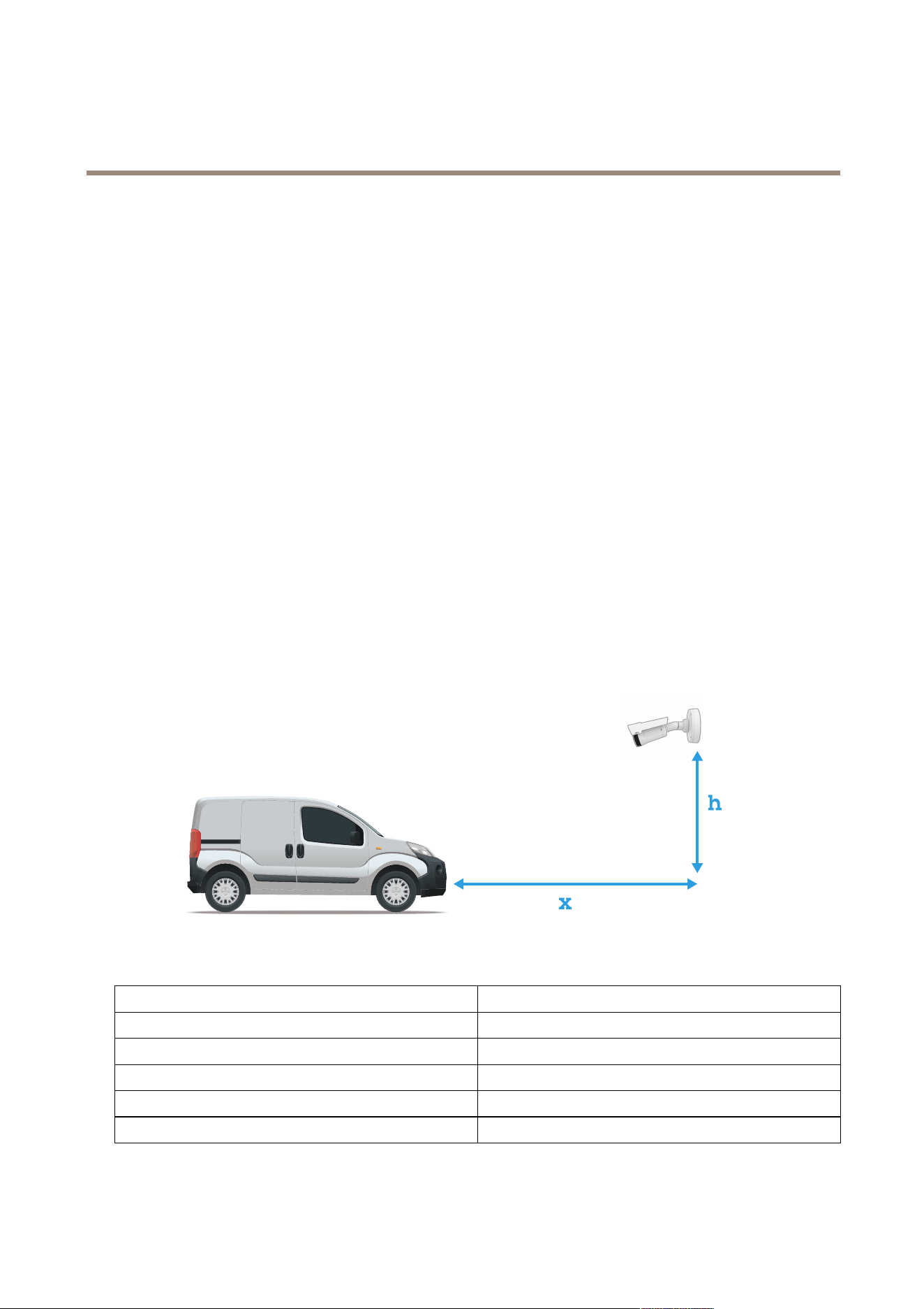
Camera mounting recommendations
• When you select the mounting location, remember that direct sunlight can distort the image, for example, during sunrise
and sunset.
• The mounting height for a camera in a Access control scenario should be half of the distance of that between the
vehicle and the camera.
• The mounting height for camera in a Free ow (slow trafc license plate recognition) scenario should be less than half of
the distance of that between the vehicle and the camera.
Access control capture distance: 2–7 m (6.6–23 ft). This example is based on the AXIS P3265–LVE-3 License Plate Verier kit.
Capture distance: (x) Mounting height (y)
2.0 m (6.6 ft) 1.0 m (3.3 ft)
3.0 m (9.8 ft) 1.5 m (4.9 ft)
4.0 m (13 ft) 2.0 m (6.6 ft)
5.0 m (16 ft) 2.5 m (8.2 ft)
7.0 m (23 ft) 3.5 m (11 ft)
Free ow capture distance: 7–20m (23–65 ft). This example is based on the AXIS P1465–LE-3 License Plate Verier kit.
4

AXIS P1465-LE-3 License Plate Verifier Kit
Basic setup
Capture distance (x) Mounting height (y)
7.0 m (23 ft) 3.0 m (9.8 ft)
10.0 m (33 ft) 4.0 m (13 ft)
15.0 m (49 ft) 6.0 m (19.5 ft)
20.0 m (65 ft) 10.0 m (33 ft)
• The camera’s mounting angle should not be larger than 30° in any direction.
Mounting angle from the side.
Mounting angle from above.
• The image of the license plate should not tilt more than 5° horizontally. If the image is tilted more than 5°, we
recommended that you adjust the camera so that the license plate is displayed horizontally in the live stream.
5

AXIS P1465-LE-3 License Plate Verifier Kit
Basic setup
Horizontal tilt.
Step-by-step guide
When you rst run the application, set up Free ow or Access control using the step-by-step guide. If you want to make changes
later on, it can be found in the Settings tab under Conguration wizard.
Free ow
In Free ow, the application can detect and read license plates in slow speed trafc on larger access roads, city centers and enclosed
areas like campuses, ports or airports. This allows for LPR-forensic search and LPR triggered events in a VMS.
1. Select Free ow and click Next.
2. Select the image rotation that corresponds to how your camera is mounted.
3. Select the number of areas of interest. Note that one area can detect plates in both directions.
4. Select the region where the camera is located.
5. Select capture type.
- License plate crop saves only the license plate.
- Vehicle crop saves the entire captured vehicle.
- Frame downsized 480x270 saves the entire image and reduces the resolution to 480x270.
- Full frame saves the entire image at full resolution.
6. Drag the anchor points to adjust the area of interest. See Adjust the area of interest on page 8 .
7. Adjust the direction of the area of interest. Click the arrow and rotate to set the direction. The direction determines how
the application registers vehicles entering or exiting the area.
8. Click Next
9. In the Protocol drop-down list, select one of the following protocols:
- TCP
- HTTP POST
6

AXIS P1465-LE-3 License Plate Verifier Kit
Basic setup
10. In the Server URL eld, type the server address and port in the following format: 127.0.0.1:8080
11. In the Device ID eld, type the name of the device or leave as is.
12. Under Event types, select one or more of the following options:
- New means the rst detection of a license plate.
- Update is either a correction of a character on a previously detected license plate, or when a a direction is
detected as the plate moves and is tracked across the image.
- Lost is the last tracked event of the license plate before it exits the image. It also contains the direction of
the license plate.
13. To turn on the feature, select Send event data to server.
14. To reduce bandwidth when using HTTP POST, you can select Do not to send images through HTTP POST.
15. Click Next.
16. If you already have a list of registered plates, choose to import as either a blocklist or allowlist.
17. Click Finish.
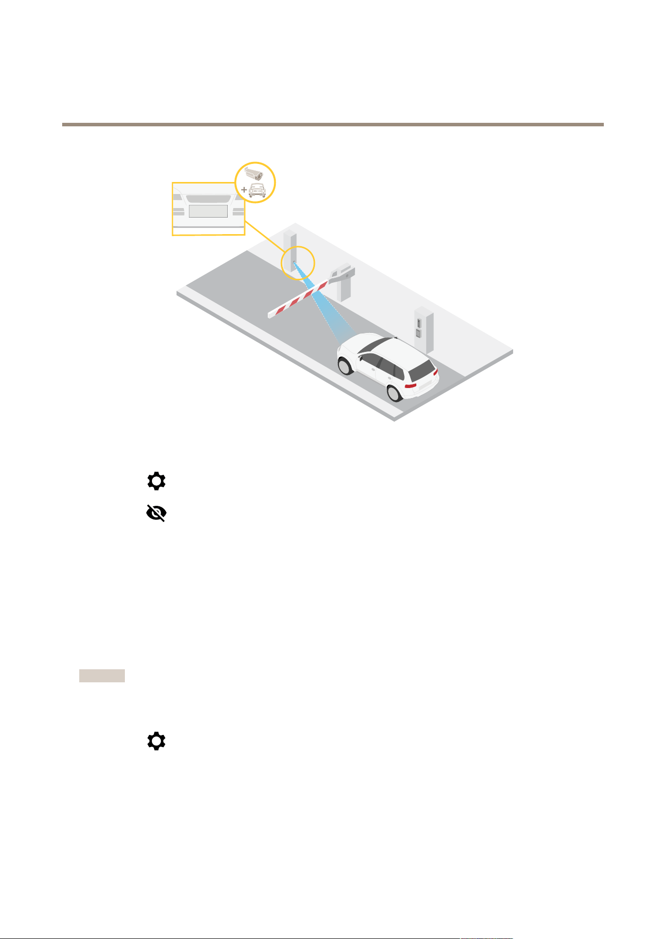
Access control
Use the setup wizard for quick and easy conguration. You can choose to Skip to leave the guide at any time.
1. Select Access control and click Next.
2. Select the type of access control to use:
- Internal I/O if you want keep list management in the camera. See Open a barrier for known vehicles using the
camera's I/O on page 24.
- Controller if you want to connect a Door controller. See .
- Relay if you want to connect to a relay module. See .
3. In the Barrier mode drop-down list, under Open from lists, select Allowlist.
4. In the Vehicle direction drop-down list, select out.
5. In the ROI drop-down-list, select the area of interest you would like to use, or if you would like to use all.
6. Click Next.
On the Image settings page:
1. Select the number of areas of interest.
2. Select the region where the camera is located.
3. Select capture type. See Adjust the image capture settings on page 9 .
4. Drag the anchor points to adjust the area of interest. See Adjust the area of interest on page 8 .
5. Adjust the direction of the area of interest. The direction determines how the application registers vehicles entering
or exiting the area.
6. Click Next
On the Event data page:
7

AXIS P1465-LE-3 License Plate Verifier Kit
Basic setup
Note
For detailed settings see: Push event information to third-party software on page 31.
1. In the Protocol drop-down list, select one of the following protocols:
- TCP
- HTTP POST
2. In the Server URL eld, type the server address and port in the following format: 127.0.0.1:8080.
3. In the Device ID eld, type the name of the device or leave as is.
4. Under Event types, select one or more of the following options:
- New means the rst detection of a license plate.
- Update is either a correction of a character on a previously detected license plate, or when a a direction is
detected as the plate moves and is tracked across the image.
- Lost is the last tracked event of the license plate before it exits the image. It also contains the direction of
the license plate.
5. To turn on the feature, select Send event data to server.
6. To reduce bandwidth when using HTTP POST, you can select Do not to send images through HTTP POST.
7. Click Next
On the Import list from a .csv le page:
1. If you already have a list of registered plates, choose to import as either a blocklist or allowlist.
2. Click Finish.
Access the application settings
1. In the camera’s webpage, go to Apps, start the application and click Open.
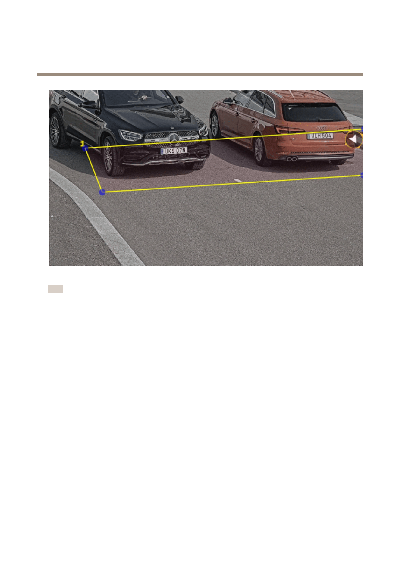
Adjust the area of interest
Note
If you move the area of interest more than 60º or if you place it outside the live view, it will automatically jump back to
default position. Make sure the region of interest stays in position after you have saved the settings.
1. Go to Settings .
2. Click Edit area of interest.
3. To improve verication and captured images, go to Zoom and adjust the slider to your needs.
4. To have the camera automatically focus on the vehicles, click Autofocus. To set the focus manually, go to Focus and
adjust it with the slider.
5. To adjust the area of interest, click anywhere in the area and drag the anchor points highlighted in blue.
6. To get the correct direction feedback in the Event log, turn the arrow to the driving direction. Click outside the area of
interest, and then click the arrow and rotate to set the direction. The direction feedback shows up in the Direction column.
Note that one area can detect plates in both directions
• To add a second of interest, select 2 in the Area of interest drop-down menu.
8
AXIS P1465-LE-3 License Plate Verifier Kit
Basic setup
Example with one area of interest.
Note
For performance reasons, keep the area of interest as small as possible.
Select region
1. Go to Settings > Image.
2. In the Region drop-down list, select your region.
Adjust the image capture settings
1. Go to Settings > Image.
2. To change the resolution of captured images, go to Resolution
3. To change the rotation of the captured image, go to Image rotation
4. To change how you save your captured images, go to Save full frame:
- License plate crop saves only the license plate.
- Vehicle crop saves the entire captured vehicle.
- Frame downsized 480x270 saves the entire image and reduces the resolution to 480x270.
- Full frame saves the entire image at full resolution.
Set up event storage
An event consists of the captured image, the license plate, the area of interest number, vehicle direction, access, and the date and time.
9

AXIS P1465-LE-3 License Plate Verifier Kit
Basic setup
This example use case explains how to store events of allowlisted license plate numbers for 30 days.
Requirements:
• Camera physically installed and connected to the network.
• AXIS License Plate Verier up and running on the camera.
• Internal storage or an SD card installed in the camera.
1. Go to Settings > Events.
2. Under Save events, select Allowlisted.
3. Under Delete events after, select 30 days.
Note
To detect an inserted SD card when the app is running, you need to restart the app. If an SD card is installed in the camera,
the app will automatically choose the SD card as the default storage.
AXIS License Plate Verier uses the cameras internal memory to save up to 1,000 events, using license plate crops as the
frame. If you use larger frames, it will vary the amount of events you can save.
To change the image capture settings, go to Settings > Image. An SD card can save up to 100,000 events using any
type of frame.
10

AXIS P1465-LE-3 License Plate Verifier Kit
Installation
Installation
To watch this video, go to the web version of this document.
help.axis.com/?&piaId=89968§ion=get-started
Installation video for the product.
Preview mode
Preview mode is ideal for installers when ne tuning the camera view during the installation. No login is required to access the
camera view in preview mode. It is available only in factory defaulted state for a limited time from powering up the device.
To watch this video, go to the web version of this document.
help.axis.com/?&piaId=89968§ion=preview-mode
This video demonstrate how to use preview mode.
11

AXIS P1465-LE-3 License Plate Verifier Kit
Configure your device
Configure your device
For users of AXIS Camera Station
Set up AXIS License Plate Verier
When a device is congured with AXIS License Plate Verier, it is considered as an external data source in AXIS Camera Station. You
can connect a view to the data source, search for the license plates that are captured by the device, and view the related image.
Note
• It requires AXIS Camera Station 5.38 or later.
• AXIS License Plate Verier requires a license.
1. Download and install the application on your device.
2. Congure the application. See AXIS License Plate Verier user manual.
3. For an existing AXIS Camera Station installation, renew your server certicate that is used to communicate with the
client. See Certicate renewal.
4. Turn on time synchronization to use the AXIS Camera Station server as the NTP server. See Server settings.
5. Add the device to AXIS Camera Station. See Add devices.
6. When the rst event is received, a data source is automatically added under Conguration > Devices > External data
sources.
7. Connect the data source to a view. See External data sources.
8. Search for license plates that are captured by the device. See Data search.
9. Click
to export the search results to a .txt le.
Basic settings
Set the scene prole
1. Go to Video > Image > Appearance.
2. In Scene prole, click Change.
Set the power line frequency
1. Go to Video > Installation > Power line frequency.
2. Click Change.
3. Select a power line frequency and click Save and restart.
Adjust the image
This section includes instructions about conguring your device.
Level the camera
To adjust the view in relation to a reference area or an object, use the level grid in combination with a mechanical adjustment
of the camera.
12

AXIS P1465-LE-3 License Plate Verifier Kit
Configure your device
1. Go to Video > Image > and click .
2. Click
to show the level grid.
3. Adjust the camera mechanically until the position of the reference area or the object is aligned with the level grid.
Reduce image processing time with low latency mode
You can optimize the image processing time of your live stream by turning on low latency mode. The latency in your live stream is
reduced to a minimum.
1. Go to System > Plain cong.
2. Select ImageSource from the drop-down list.
3. Go to ImageSource/I0/Sensor > Low latency mode and select On.
4. Click Save.
Select exposure mode
To improve image quality for specic surveillance scenes, use exposure modes. Exposure modes lets you control aperture, shutter
speed, and gain. Go to Video > Image > Exposure and select between the following exposure modes:
• For most use cases, select Automatic exposure.
• For environments with certain articial lighting, for example uorescent lighting, select Flicker-free.
Select the same frequency as the power line frequency.
• For environments with certain articial light and bright light, for example outdoors with uorescent lighting at night and
sun during daytime, select Flicker-reduced.
Select the same frequency as the power line frequency.
• To lock the current exposure settings, select Hold current.
Compensate for barrel distortion
Barrel distortion is a phenomenon where straight lines appear increasingly bent closer to the edges of the frame. A wide eld of view
often creates barrel distortion in an image. Barrel distortion correction compensates for this distortion.
Note
Barrel distortion correction affects the image resolution and eld of view.
1. Go to Video > Installation > Image correction.
2. Turn on Barrel distortion correction (BDC).
3. Use the slider to improve the image.
Verify the pixel resolution
To verify that a dened part of the image contains enough pixels to, for example, recognize license plates, you can use the pixel
counter.
13
AXIS P1465-LE-3 License Plate Verifier Kit
Configure your device
ABC 123
1. Go to Video > Image.
2. Click
.
3. Click for Pixel counter.
4. In the camera’s live view, adjust the size and position of the rectangle around the area of interest, for example where you
expect license plates to appear.
5. You can see the number of pixels for each of the rectangle’s sides, and decide if the values are enough for your needs.
View and record video
This section includes instructions about conguring your device. To learn more about how streaming and storage works, go to .
Reduce bandwidth and storage
Important
Reducing the bandwidth can result in loss of details in the image.
1. Go to Video > Stream.
2. Click
in the live view.
3. Select Video format H.264.
4. Go to Video > Stream > General and increase Compression.
5. Go to Video > Stream > H.264 and H.265 encoding and do one or more of the following:
- Select the Zipstream level that you want to use.
14

AXIS P1465-LE-3 License Plate Verifier Kit
Configure your device
Note
The Zipstream settings are used for both H.264 and H.265.
- Turn on Dynamic FPS.
- Turn on Dynamic GOP and set a high Upper limit GOP length value.
Note
Most web browsers don’t support H.265 decoding and because of this the device doesn’t support it in its web interface.
Instead you can use a video management system or application that supports H.265 decoding.
Set up network storage
To store recordings on the network, you need to set up your network storage.
1. Go to System > Storage.
2. Click
Add network storage under Network storage.
3. Type the IP address of the host server.
4. Type the name of the shared location on the host server under Network share.
5. Type the username and password.
6. Select the SMB version or leave it on Auto.
7. Select Add share even if connection fails if you experience temporary connection issues, or if the share is not yet
congured.
8. Click Add.
Record and watch video
Record video directly from the camera
1. Go to Video > Image.
2. To start a recording, click
.
If you haven’t set up any storage, click
and . For instructions on how to set up network storage, see Set up
network storage on page 15
3. To stop recording, click
again.
Watch video
1. Go to Recordings.
2. Click
for your recording in the list.
Verify that no one has tampered with the video
With signed video, you can make sure that no one has tampered with the video recorded by the camera.
1. Go to Video > Stream > General and turn on Signed video.
15

AXIS P1465-LE-3 License Plate Verifier Kit
Configure your device
2. Use AXIS Camera Station (5.46 or later) or another compatible video management software to record video. For
instructions, see the AXIS Camera Station user manual.
3. Export the recorded video.
4. Use AXIS File Player to play the video. Download AXIS File Player.
indicates that no one has tampered with the video.
Note
To get more information about the video, right-click the video and select Show digital signature.
Set up rules for events
You can create rules to make your device perform an action when certain events occur. A rule consists of conditions and actions.
The conditions can be used to trigger the actions. For example, the device can start a recording or send an email when it detects
motion, or show an overlay text while the device is recording.
To learn more, check out our guide Get started with rules for events.
Trigger an action
1. Go to System > Events and add a rule. The rule denes when the device will perform certain actions. You can set
up rules as scheduled, recurring, or manually triggered.
2. Enter a Name.
3. Select the Condition that must be met to trigger the action. If you specify more than one condition for the rule, all of the
conditions must be met to trigger the action.
4. Select which Action the device should perform when the conditions are met.
Note
If you make changes to an active rule, the rule must be turned on again for the changes to take effect.
Note
If you change the denition of a stream prole that is used in a rule, then you need to restart all the rules that use that
stream prole.
Record video when the camera detects a license plate
This example explains how to set up the camera to start recording to the SD card when the camera detects an object. The recording
will include ve seconds before detection and one minute after detection ends.
Before you start:
• Make sure you have an SD card installed.
Make sure that AXIS Licence Plate Verier is running:
1. Go to Apps > AXIS License Plate Verier.
2. Start the application if it is not already running.
3. Make sure you have set up the application according to your needs.
Create a rule:
1. Go to System > Events and add a rule.
16

AXIS P1465-LE-3 License Plate Verifier Kit
Configure your device
2. Type a name for the rule.
3. In the list of conditions, under Application, select ALPV.PlateInView.
4. In the list of actions, under Recordings, select Record video while the rule is active.
5. In the list of storage options, select SD_DISK.
6. Select a camera and a stream prole.
7. Set the prebuffer time to 5 seconds.
8. Set the postbuffer time to 1 minute.
9. Click Save.
Send an email automatically if someone spray paints the lens
Activate the tampering detection:
1. Go to System > Detectors > Camera tampering.
2. Set a duration for Trigger after. The value indicates the time that must pass before an email is sent.
3. Turn on Trigger on dark images to detect if the lens is sprayed, covered, or rendered severely out of focus.
Add an email recipient:
4. Go to System > Events > Recipients and add a recipient.
5. Type a name for the recipient.
6. Select Email.
7. Type an email address to send the email to.
8. The camera doesn’t have it’s own email server, so it has to log into another email server to send mails. Fill in the rest of the
information according to your email provider.
9. To send a test email, click Test.
10. Click Save.
Create a rule:
11. Go to System > Events > Rules and add a rule.
12. Type a name for the rule.
13. In the list of conditions, under Video, select Tampering.
14. In the list of actions, under Notications, select Send notication to email and then select the recipient from the list.
15. Type a subject and a message for the email.
16. Click Save.
17

AXIS P1465-LE-3 License Plate Verifier Kit
Manage lists
Manage lists
Add detected license plate to list
A license plate can be added directly to a list after being detected by the application.
1. Click the Event log tab.
2. Go to Latest Event.
3. Click Add to list next to the license plate that you’d like to add.
4. Select the list you would like to add the license plate in the list drop down menu.
5. Click Append.
Add descriptions to license plates
To add a description to a license plate in the list:
• Go to List management.
• Select the license plate you want to edit and click the pen icon.
• Type the relevant information in the Description eld at the top of the list
• Click the disk icon to save.
Customize list names
You can change the name of any of the lists to t your specic use case.
1. Go to List management.
2. Go to the list menu of the list you want to change.
3. Select Rename.
4. Type the name of the list.
The new list name will be updated in any existing congurations.
Import allowlisted license plate numbers
You can import allowlisted license plate numbers from a .csv le on the computer. In addition to the license plate number, you can
also add comments for each license plate number in the .csv le.
The structure of the .csv le must look like this: license plate,date,description
Example
Only license plate: AXIS123
License plate + description: AXIS123,,John Smith
License plate + date + description: AXIS123,2022-06-08,John Smith
1. Go to List management
2. Go to the context menu next to Allowlist and select Import from le.
18

AXIS P1465-LE-3 License Plate Verifier Kit
Manage lists
3. Browse to select a .csv le on the computer.
4. Click OK.
5. Check that the imported license plate numbers appear in the Allowlist.
Share license plate lists with other cameras
You can share the license plate lists with other cameras on the network. The synchronization will override all current license plate
lists in the other cameras.
1. Go to List management.
2. Under Camera synchronization, type the IP address, username and password.
3. Click +.
4. Click Camera synchronization.
5. Check that the date and time under Last sync updates accordingly.
Schedule lists
Lists can be scheduled to only be active during certain times during certain days of the week. To schedule a list:
• Go to List management.
• Go the list menu of the list you want to schedule.
• Select Schedule in the pop-up menu.
• Select the start and end time, and the day when the list should be active.
• Click the button next to Enabled.
• Click Save.
19

AXIS P1465-LE-3 License Plate Verifier Kit
Additional settings
Additional settings
Congure text overlay
A text overlay shows the following event information in the live view: weekday, month, time, year, license
plate number.
1. Go to Settings > Image.
2. Activate Text overlay.
3. Set Overlay duration to a value between 1 and 9 seconds.
4. Select either date, time and license plate (Datetime + LP), or just the license plate (LP).
5. Check that the overlay appears in the live view.
Detect license plates in low-light conditions
Each detection gets a score by the algorithm, this is called the sensitivity level (condence parameter). Detections that have a lower
score than the selected level will not show up in the list of events.
For scenes with low lighting you can lower the sensitivity level.
1. Go to Settings > Detection parameters.
2. Adjust the slider under Sensitivity level. To avoid false detections, we recommend that you lower the threshold value
with 0.05 at a time.
3. Check that the algorithm detects the license plates as expected.
Allow fewer characters on license plates
The application has a default minimum number of characters for a license plate to be detected. The default minimum number of
characters is ve. You can congure the application to detect license plates with fewer characters.
1. Go to Settings > Detection parameters.
2. In the Minimum number of characters eld, type the minimum number of characters you want to allow.
3. Check that the application detects license plates as expected.
Allow only exact matches of license plates
The matching algorithm automatically allows a deviation of one character when matching the detected license plate against the
allowlist or blocklist. However, some scenarios need an exact match of all characters of the license plate.
1. Go to List management.
2. Click to activate Strict matching.
3. Check that the application matches the license plates as expected.
Allow more than one character deviation when matching license plates
The matching algorithm automatically allows a deviation of one character when matching the detected license plate against the
allowlist or blocklist. However, you can allow more than one character deviation.
20

AXIS P1465-LE-3 License Plate Verifier Kit
Additional settings
1. Go to Settings > Detection parameters.
2. Under Allowed character deviation, select the number of characters that are allowed to be different.
3. Check that the application matches the license plates as expected.
Give limited access to operators
Operators can be given a limited access to the app using an URL. This way they only have access to the Event log and List
management. The URL can be found under Settings > User rights.
Set up secure connection
To protect communication and data between devices, for example between the camera and the door controller, set up a secure
connection with HTTPS using certicates.
1. Go to Settings > Security.
2. Under HTTPS, Enable HTTPS.
3. Select either Self-signed or CA-signed.
Note
Find out more about HTTPS and how to use it at .
Backup and restore app settings
You can backup and restore settings made in the app related to image capture, security, detection and integration. If something
should go wrong, you can now restore the settings you have backed up.
To backup app settings:
• Go to Settings > Maintenance.
• Click Backup conguration.
A JSON le will be downladed to you downloads folder.
To restore app settings:
• Go to Settings > Maintenance.
• Click Restore conguration.
Select the JSON le containing the backup.
The setting are restored automatically.
Clear all events
After you set up the app, it can be a good idea to clear the records of any images or captured plates from the setup process.
To clear all images and plates from the database:
Go to Settings > Maintenance.
• Click Clear all recognition results.
• Click Yes.
21

AXIS P1465-LE-3 License Plate Verifier Kit
Additional settings
Use virtual ports to trigger actions
Virtual ports can be used together with access control to trigger any kind of action. This example explains how to set up
AXIS License Plate Verier together with the camera’s I/O port to display a text overlay using a virtual port.
Requirements:
• Camera physically installed and connected to the network.
• AXIS License Plate Verier up and running on the camera.
• Cables connected between the barrier and the camera’s I/O port.
• Basic setup done. See .
1. Go to the application’s webpage and select the Settings tab.
2. Go to Access control.
3. Under Access control , select the Type drop-down list, select Internal I/O.
4. Select the I/O output #.
5. Select a port in the Virtual port drop-down list.
6. In the Barrier mode drop-down list, select Open to all.
7. In the Vehicle direction drop-down list, select any.
8. In the ROI drop-down-list, select the area of interest you would like to use, or if you would like to use all.
9. In the camera’s webpage, go to System > Events.
10. Click Add rule.
11. Under Condition select Virtual input is active and the port number you have selected.
12. Under Action, select Use overlay text.
13. Select Video channels.
14. Type the text you want displayed.
15. Add the duration of the text.
16. Click Save.
17. Go to Video > Overlays.
18. Go to Overlays.
19. Select Text in the drop-down menu and click +.
20. Type #D or select the modier in the Modiers drop-down list.
21. Check that the text overlay is displayed when a vehicle enters the region of interest in the live view.
22
AXIS P1465-LE-3 License Plate Verifier Kit
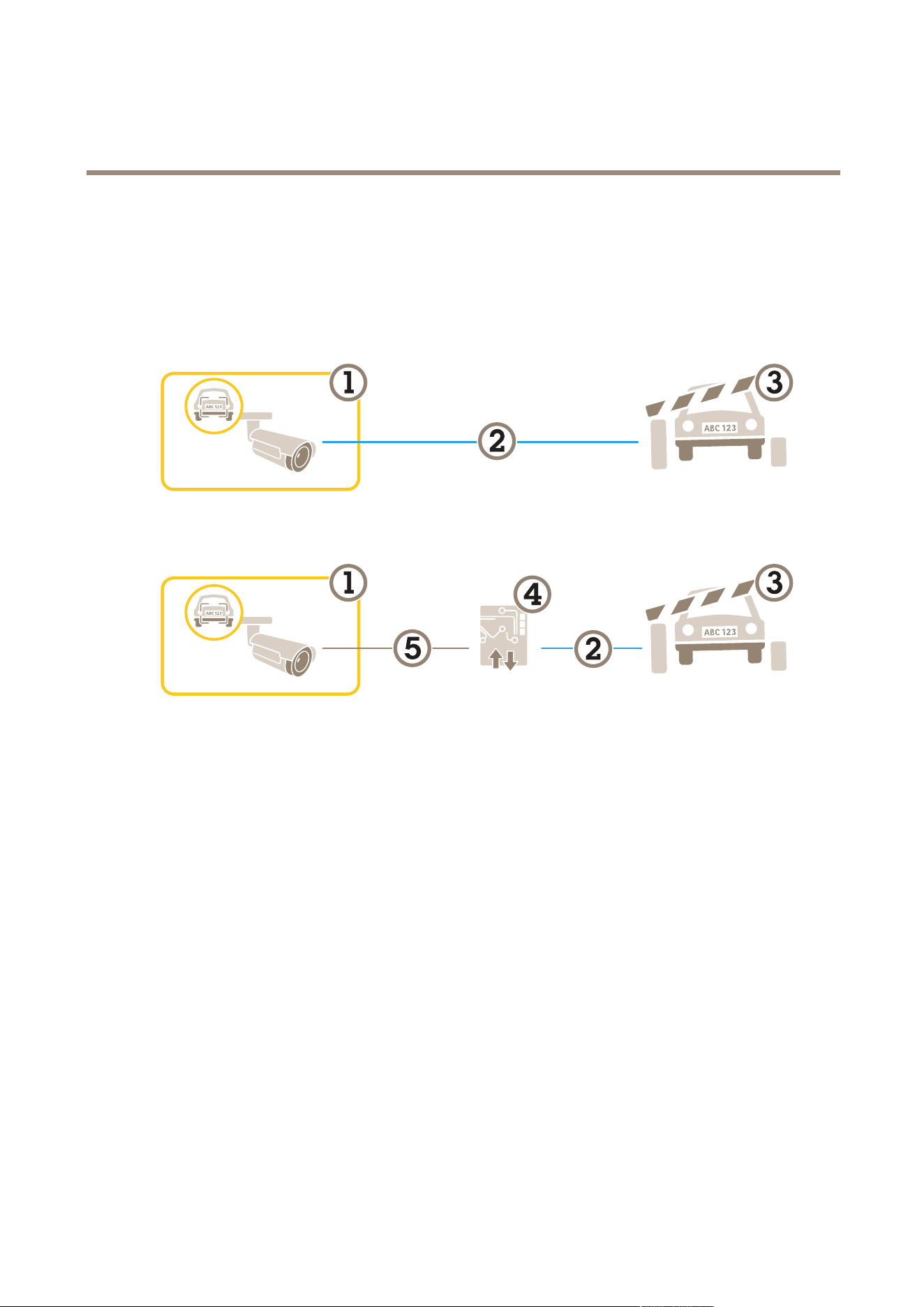
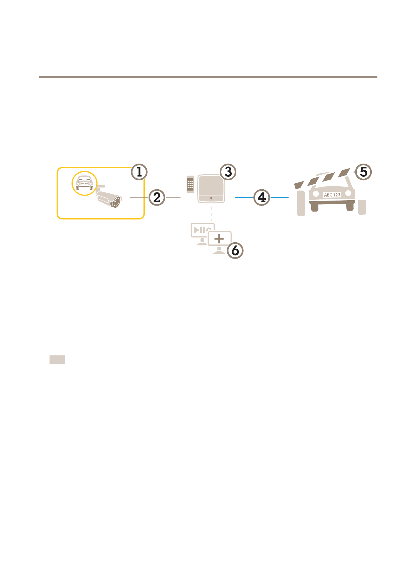
Vehicle entry and exit scenario
Vehicle entry and exit scenario
In the scenario for vehicle entry and exit, the application reads the vehicle license plate captured by the camera and veries the
license plate against a list of authorized or unauthorized license plate numbers stored in the camera.
This scenario requires the application embedded in a camera with I/O support or a connected I/O relay module to open and close the
barrier.
Two possible setups for the vehicle entry and exit scenario.
1
Axis camera with AXIS License Plate Verier
2
I/O communication
3
Barrier
4
Axis I/O relay module
5
IP communication
Open a barrier for known vehicles using a relay module
This example use case explains how to set up AXIS License Plate Verier together with a relay module to open a barrier for a known
vehicle driving through a specic region of interest (ROI) into, let’s say a parking area.
Requirements:
• Camera physically installed and connected to the network.
• AXIS License Plate Verier up and running on the camera.
• Cables connected between the barrier and the relay module.
• Basic setup done. See Basic setup on page 4 .
1. Go to the camera’s webpage, select Settings and open AXIS License Plate Verier.
2. Go to the relay module’s webpage and make sure the relay port is connected to the camera’s I/O port.
3. Copy the relay module’s IP address.
4. Go back to AXIS License Plate Verier.
23

AXIS P1465-LE-3 License Plate Verifier Kit
Vehicle entry and exit scenario
5. Go to Settings > Access control.
6. Go to Type and select Relay in the drop-down list.
7. In the I/O output drop-down list, select the I/O port that is connected to the barrier.
8. In the Barrier mode drop-down list, select Open from lists and then check Allowlist.
9. In the Vehicle direction drop-down list, select in.
10. In the ROI drop-down list, select the area of interest that covers the trafc lane.
11. Enter the following information:
- the IP address for the relay module in format 192.168.0.0
- the username for the relay module
- the password for the relay module
12. To make sure the connection works, click Connect.
13. To activate the connection, click Turn on integration.
14. Go to the List management tab
15. Enter the license plate number in the Allowlist eld.
Note
The physical input ports 1 to 8 on the relay module correspond to ports 1 to 8 in the drop-down list. However, the relay ports
1 to 8 on the relay module correspond to ports 9 to 16 in the drop-down list. This is valid even if the relay module only
has 8 ports.
16. Check that the application identies the license plate number in the allowlist as a known vehicle and that the barrier
opens as expected.
Open a barrier for known vehicles using the camera's I/O
This example explains how to set up AXIS License Plate Verier together with the camera’s I/O port to open a barrier for a known
vehicle entering, for example, a parking area.
Requirements:
• Camera physically installed and connected to the network.
• AXIS License Plate Verier up and running on the camera.
• Cables connected between the barrier and the camera’s I/O port.
• Basic setup done. See .
24

AXIS P1465-LE-3 License Plate Verifier Kit
Vehicle entry and exit scenario
To watch this video, go to the web version of this document.
help.axis.com/?&piaId=89968§ion=open-a-barrier-for-known-vehicles-using-the-cameras-io
Open a barrier for known vehicles using the camera's I/O
1. Go to the application’s webpage and select the Event log tab and add detected license plates to a list. See Add detected
license plate to list on page 18
2. To edit the lists directly, go to the List management tab.
3. Enter the authorized license plate numbers in the Allowlist eld.
4. Go to the Settings tab.
5. Under Access control , select the Type drop-down list, select Internal I/O.
6. Select the I/O output #.
7. In the Barrier mode drop-down list, select Open from lists and then check Allowlist.
8. In the Vehicle direction drop-down list, select in.
9. In the ROI drop-down-list, select the area of interest you would like to use, or if you would like to use all.
10. Check that the application identies the license plate number in the allowlist as a known vehicle and that the barrier
opens as expected.
Note
You can change the name of any of the lists to t your specic use case.
Get notied about an unauthorized vehicle
This example explains how to set up the application so that an event that triggers a notication can be created in the camera.
Requirements:
• Basic setup done. See Basic setup on page 4 .
1. Go to List management.
2. Enter the license plate number in the Blocklist eld.
3. Go to the camera’s webpage.
4. Go to Settings > Events and set up an action rule with the application as a condition and with a notication as an action.
5. Check that the application identies the added license plate number as an unauthorized vehicle and that the action
rule runs as expected.
25
AXIS P1465-LE-3 License Plate Verifier Kit
Vehicle access control scenario
Vehicle access control scenario
In the scenario for vehicle access control, the application can be connected to an Axis network door controller to congure access
rules, create schedules for access times, and handle vehicle access not only for employees, but also, for example, visitors and suppliers.
For backup, use an access system involving a door controller and card reader. To set up the door controller and the card reader, see
the user documentation at axis.com
1
Axis camera with AXIS License Plate Verier
2
IP communication
3
Axis network door controller with card reader
4
I/O communication
5
Barrier
6
Optional third-party software
Connect to a door controller
In this example we connect the camera to a network door controller which means the camera works as a sensor. The camera forwards
the information to the controller which in turn analyzes the information and triggers the events.
Note
When switching between the AXIS License Plate Verier and AXIS Entry Manager, make sure to refresh the webpages to get
access to all parameters.
Requirements:
• Camera and door controller physically installed and connected to the network.
• AXIS License Plate Verier up and running on the camera.
• Basic setup done. See Basic setup on page 4 .
26

AXIS P1465-LE-3 License Plate Verifier Kit
Vehicle access control scenario
To watch this video, go to the web version of this document.
help.axis.com/?&piaId=89968§ion=connect-to-a-door-controller
How to get the application up and running with AXIS A1001 Door Controller.
Hardware conguration in AXIS Entry Manager
1. Go to AXIS Entry Manager and start a new hardware conguration under Setup.
2. In the hardware conguration, rename the network door controller to “Gate controller”.
3. Click Next.
4. In Congure locks connected to this controller, clear the Door monitor option.
5. Click Next.
6. In Congure readers connected to this controller, clear the Exit reader option.
7. Click Finish.
Conguration in AXIS License Plate Verier
1. Go the AXIS License Plate Verier webpage.
2. Go to the Settings > Access control.
3. Go to Type and select Controller in the drop-down list.
4. Enter the following information:
- the IP address for the controller in format 192.168.0.0
- the username for the controller
- the password for the controller
5. Click Connect.
6. If the connection is successful, “Gatecontroller” shows up in the Network Door Controller name drop-down list. Select
“Gatecontroller”.
7. In the Reader name drop-down list, select the reader connected to the door “Gatecontroller”, for example “Reader
entrance”. These names can be changed in AXIS Entry Manager.
8. To activate the connection, select Turn on integration.
9. Enter one of the user’s license plate number, or use the default, in the test eld and click Test integration. Check that the
test was successful.
Congure users, groups, doors, and schedules in AXIS Entry Manager
1. Go to AXIS Entry Manager.
2. Go to Access Management.
3. Go to Doors > Add identication type.
27
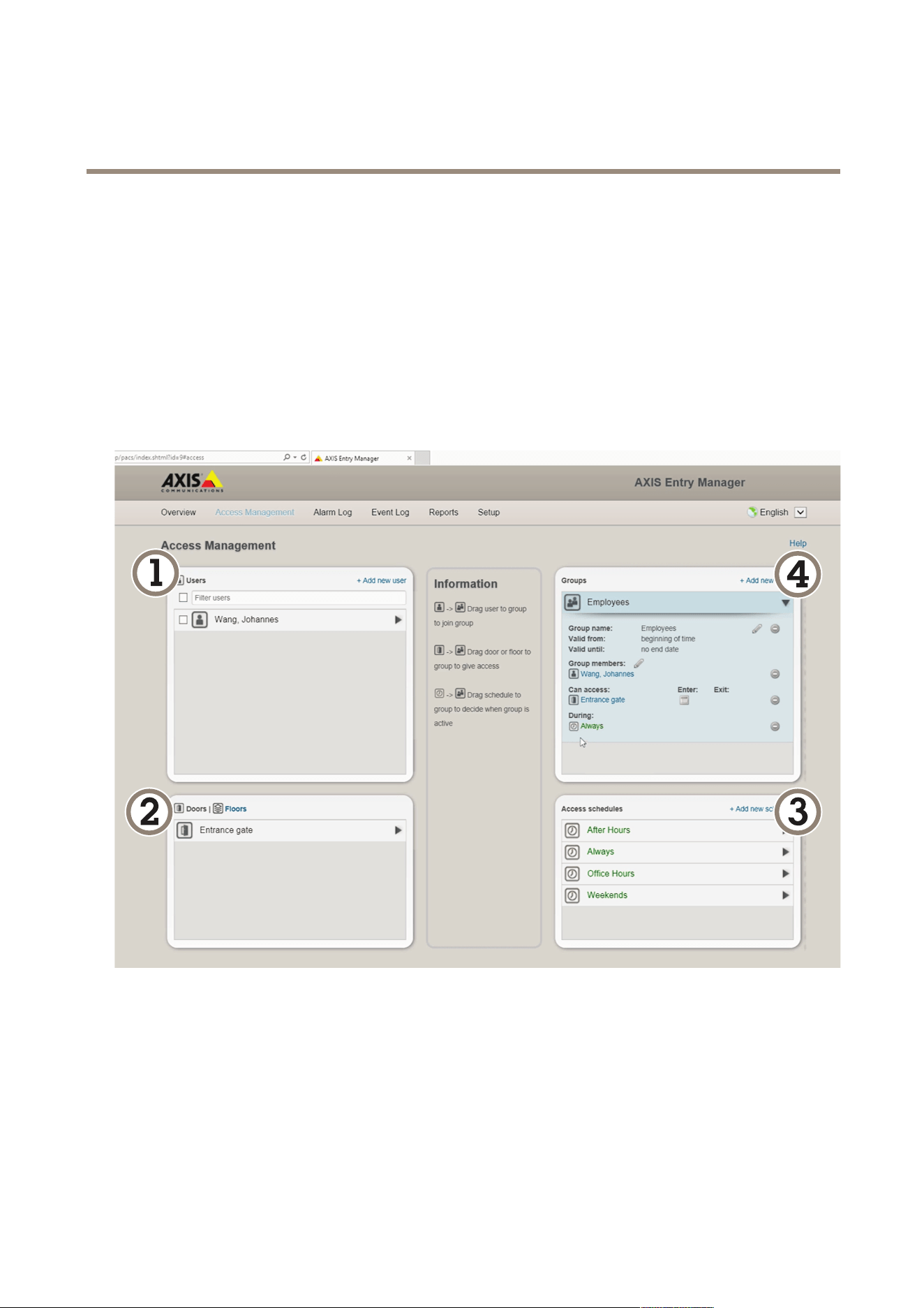
AXIS P1465-LE-3 License Plate Verifier Kit
Vehicle access control scenario
4. In the Credentials needed drop-down list, select License plate only.
5. To set limits for when the identication type can be used, drag and drop a Schedule to the door.
6. Add users and, for each user, add the credential License plate.
7. Click Add credential again and enter the license plate information.
8. Click Add new group and enter the information.
9. To add users to a group, drag and drop Users to the user group.
10. To give users access, drag and drop the Door to the user group.
11. To limit the access time, drag and drop a Schedule to the user group.
Overview of AXIS Entry Manager user interface.
1
Users
2
Doors
3
Schedules
4
User groups
Connect to AXIS Secure Entry
This example describes connecting an Axis door controller in AXIS Camera Station and AXIS Secure Entry with AXIS Licence Plate
Verier.
28

AXIS P1465-LE-3 License Plate Verifier Kit
Vehicle access control scenario
Requirements:
• Camera and door controller physically installed and connected to the network.
• AXIS License Plate Verier up and running on the camera.
• AXIS Camera Station client version 5.49.449 and up.
• Basic setup done. See Basic setup on page 4 .
In AXIS Camera Station, see Add a reader.
In the AXIS License Plate Verier app:
1. In the Settings tab, go to Conguration wizard and click Start.
2. Select Access Control.
3. Select Secure Entry, and click Next.
In AXIS Camera Station:
4. Type the IP address of the door controller, available in the device list in AXIS Camera Station > Conguration > Other
Devices.
5. To add a Authentication key, go to AXIS Camera Station > Conguration > Encrypted communication.
6. Go to External Peripheral Authentication Key and click Show authentication key.
7. Click Copy key.
In the AXIS License Plate Verier app:
8. Go to Authentication key in the conguration wizard and paste the key.
9. Click Connect.
10. Select the Door controller name in the drop-down menu.
11. Select the Reader name in the drop-down menu.
12. Check Turn on integration.
13. Click Next.
14. Adjust the area of interest. See Adjust the area of interest on page 8 .
15. Click Next twice and then Finish.
29

AXIS P1465-LE-3 License Plate Verifier Kit
Search for specific events
Search for specific events
Use the search feature to search for events using a number of criteria.
1. Go to the application’s webpage and select the Event log tab.
2. Select the date in the Start time and End time calendar menus.
3. Enter the license plate in the Plate eld, if you want to search for a plate.
4. Click the ROI drop down menu to select which region of interest, or if both should be relevant in the search.
5. select Direction to lter by entry or exit.
6. To lter out license plates that belong to either the allow- or blocklist, click the Access drop down menu.
7. Click Search.
To go back to the live updated log, click Live.
Note
Once a search has completed you can se a brief summary of statistics pertaining to that search.
To show any description related the license plates, click the settings icon and check Show description.
Export and share search results
To export any search result as a CSV le with the statistics at that time, click Export to save the results as a CSV le
To copy the API as a link which can be used to export data to third party systems, click Copy search link.
30

AXIS P1465-LE-3 License Plate Verifier Kit
Integration
Integration
Use proles to push events to multiple servers
With proles, you can push an event to different servers using different protocols at the same time. To use proles:
1. Select a prole in the Proles drop-down menu.
2. Congure the rule. See Push event information to third-party software on page 31.
3. Click Save.
4. Select a new prole in the Proles drop-down menu.
Push event information to third-party software
Note
The application sends the event information in JSON format. For more information, log in using your MyAxis account, go to
the AXIS VAPIX Library and select AXIS License Plate Verier
With this feature you can integrate third-party software by pushing the event data through TCP or HTTP POST.
Before you start:
• The camera must be physically installed and connected to the network.
• AXIS License Plate Verier must up and running on the camera.
1. Go to Integration > Push events.
2. In the Protocol drop-down list, select one of the following protocols:
- TCP
- HTTP POST
- Type the user name and password.
3. In the Server URL eld, type the server address and port in the following format: 127.0.0.1:8080
4. In the Device ID eld, type the name of the device or leave as is.
5. Under Event types, select one or more of the following options:
- New means the rst detection of a license plate.
- Update is either a correction of a character on a previously detected license plate, or when a a direction is
detected as the plate moves and is tracked across the image.
- Lost is the last tracked event of the license plate before it exits the image. It also contains the direction of
the license plate.
6. To turn on the feature, select Send event data to server.
7. To reduce bandwidth when using HTTP POST, you can select Do not to send images through HTTP POST.
8. Click Save.
Note
To push events using HTTP POST, you can use an authorization header instead of a user name and password, go to the
Auth-Header eld, and add a path to an authentication API.
31

AXIS P1465-LE-3 License Plate Verifier Kit
Integration
Send images of license plates to a server
With this feature you can push images of the license plates to a server through FTP.
Before you start:
• The camera must be physically installed and connected to the network.
• AXIS License Plate Verier must up and running on the camera.
1. Go to Integration > Push events.
2. In the Protocol drop-down list, select FTP.
3. In the Server URL eld, type the server address in the following format: ftp://10.21.65.77/LPR.
4. In the Device ID eld, type the name of the device. A folder with this name will be created for the images. Images are
created using the following format: timestamp_area of interest_direction_carID_license plate text_country.jpg.
5. Type the username and password for the FTP server.
6. Select the path and name modiers for the lenames.
7. Click Done.
8. Under Event types, select one or more of the following options:
- New means the rst detection of a license plate.
- Update is either a correction of a character on a previously detected license plate, or when a a direction is
detected as the plate moves and is tracked across the image.
- Lost is the last tracked event of the license plate before it exits the image. It also contains the direction of
the license plate.
Note
Direction is only included in the lename when Lost or Update is selected.
9. To turn on the feature, select Send event data to server.
10. Click Save.
Note
Note that the image varies depending on what type of capture mode you have selected, see Adjust the image capture
settings on page 9 .
Note
If push events fail, the app will resend up to the rst 100 failed events to the server.
When using FTP in push events to a Windows server, do not use %c for naming of images that gives you date and time.
This is due to the fact that Windows does not accept the naming set by the function %c for date and time. Note that
this is not an issue when using a Linux server.
Direct integration with 2N
This example describes direct integration with a 2N IP device.
Set up an account in your 2N device:
1. Go to 2N IP Verso.
2. Go to Services > HTTP API > Account 1.
32

AXIS P1465-LE-3 License Plate Verifier Kit
Integration
3. Select Enable account.
4. Select Camera access.
5. Select License plate recognition.
6. Copy the IP address.
In the AXIS License Plate Verier app:
1. Go to Integration > Direct integration.
2. Add the IP address or URL to the 2N device.
3. Select Connection type.
4. Select what the Barrier is used for.
5. Type your username and password.
6. Click Enable integration.
7. Click Save.
To check in the integration is working:
1. Go to 2N IP Verso.
2. Go to Status > Events.
Integrate with Genetec Security Center
This example describes setting up a direct integration with Genetec Security Center.
In Genetec Security Center:
1. Go to Overview.
2. Make sure that Database, Directory and License are online. If they’re not, run all Genetec and SQLEXPRESS services
in Windows.
3. Go to Genetec Cong Tool > Plugins.
4. Click Add an entity.
5. Go to Plugin and select LPR plugin.
6. Click Next.
7. Click Next.
8. Click Next.
9. Select the LPR plugin you’ve added and go to Data sources .
Under ALPR reads API:
10. Check Enabled.
11. In Name, type: Plugin REST API.
12. In API path prex, type: lpr.
13. In REST port, select 443.
33

AXIS P1465-LE-3 License Plate Verifier Kit
Integration
14. In WebSDK host, type: localhost.
15. In WebSDK port, select 443.
16. Check Allow self signed certicates.
Under Security Center events data source:
17. Check Enabled.
18. In Name, type Security Center Lpr Events.
19. In Processing frequency, select 5 sec in the drop-down menu.
20. Go to the Data sinks tab.
21. Click +.
22. In Type, select Database.
23. Select and congure the database:.
- Check Enabled.
- In Source, check Plugin REST API and Native ALPR Events.
- In Name, type Reads DB.
- In Include, check Reads, Hits and Images.
- Go to the Resources tab.
- Click Delete the database and then Create a database.
Create an API user:
24. Go to Cong Tool > User Management.
25. Click Add an entity.
26. Select User.
27. Type a username and password. Leave the other elds unchanged.
28. Select the added user and go to the Privileges tab.
29. Check to allow everything under Application privileges.
30. Check to allow Third-party ALPR reads API.
31. Click Apply.
In the AXIS License Plate Verier app:
1. Go to the Integration tab.
2. Select Genetec Security Center in the drop-down list.
3. In URL/IP, type your address according to this template: https://server-
address/api/V1/lpr/lpringestion/reads.
4. Type in your Genetec username and password.
5. Click Enable integration.
6. Go to the Settings tab.
34

AXIS P1465-LE-3 License Plate Verifier Kit
Integration
7. Under Security > HTTPS.
8. Select Self-signed, or CA-signed depending on the settings in Genetec Security Center.
In Genetec Security Center:
1. Go to Genetec Security desk.
2. Under Investigation, click Reads.
3. Go to the Reads tab.
4. Filter the result to your needs.
5. Click Generate report.
Note
You can also read Genetec’s documentation on integrating third party ALPR plugins. You can do that here (requires registration).
35
AXIS P1465-LE-3 License Plate Verifier Kit
The device interface
The device interface
To reach the device interface, type the device’s IP address in a web browser.
Note
Support for the features and settings described in this section varies between devices.
Show or hide the main menu.
Access the product help.
Change the language.
Set light theme or dark theme.
The user menu contains:
• Information about the user who is logged in.
•
Change user : Log out the current user and log in a new user.
•
Log out : Log out the current user.
The context menu contains:
• Analytics data: Accept to share non-personal browser data.
• Feedback: Share any feedback to help us improve your user experience.
• Legal: View information about cookies and licenses.
• About: View device information, including rmware version and serial number.
• Legacy device interface: Change the device interface to the legacy device interface.
Status
NTP sync
Shows NTP synchronization information, including if the device is in sync with an NTP server and the time remaining until
the next sync.
NTP settings: Click to go to the Date and time page where you can change the NTP settings.
Device info
Shows device information, including rmware version and serial number.
Upgrade rmware: Click to go to the Maintenance page where you can do a rmware upgrade.
Ongoing recordings
Recordings: Shows each ongoing recording and its source. For more information, see Recordings on page 48
Shows the storage space where the recording is saved.
36

AXIS P1465-LE-3 License Plate Verifier Kit
The device interface
Connected clients
The list shows all clients that are connected to the device.
Update: Click to refresh the list.
Video
Click to play the live video stream.
Click to freeze the live video stream.
Click to take a snapshot of the live video stream. The le is saved in the ‘Downloads’ folder on your computer. The image
le name is [snapshot_YYYY_MM_DD_HH_MM_SS.jpg]. The size of the snapshot depends on the compression that is applied
from the specic web-browser engine where the snapshot is received, therefore, the snapshot size may vary from the actual
compression setting that is congured in the device.
Click to show I/O output ports. Use the switch to open or close the circuit of a port, for example to test external
devices.
Click to manually turn on or turn off the IR illumination.
Click to access onscreen controls:
• Predened controls: Turn on to use the available onscreen controls.
• Custom controls: Click
Add custom control to add an onscreen control.
Click to manually turn on the heater for a selected period of time.
Click to start a continuous recording of the live video stream. Click again to stop the recording. If a recording is ongoing, it
will resume automatically after a reboot.
Click to show the storage that is congured for the device. To congure the storage you need to be logged in as an
administrator.
Click to access more settings:
• Video format: Select the encoding format to use in the live view.
• Client stream information: Turn on to show dynamic information about the video stream used by the browser that
shows the live video stream. The bitrate information differs from the information shown in a text overlay, because of
different information sources. The bitrate in the client stream information is the bitrate of the last second, and it
comes from the encoding driver of the device. The bitrate in the overlay is the average bitrate of the last 5 seconds,
and it comes from the browser. Both values cover only the raw video stream and not the additional bandwidth
generated when it’s transported over the network through UDP/TCP/HTTP.
• Adaptive stream: Turn on to adapt the image resolution to the viewing client’s actual display resolution, to improve
the user experience and help prevent a possible overload of the client’s hardware. The adaptive stream is only
applied when you view the live video stream in the web interface in a browser. When adaptive stream is turned on,
the maximum frame rate is 30 fps. If you take a snapshot while adaptive stream is turned on, it will use the image
resolution selected by the adaptive stream.
37

AXIS P1465-LE-3 License Plate Verifier Kit
The device interface
• Level grid: Click to show the level grid. The grid helps you decide if the image is horizontally aligned. Click
to hide it.
• Pixel counter: Click
to show the pixel counter. Drag and resize the box to contain your area of interest. You can
also dene the pixel size of the box in the Width and Height elds.
• Refresh: Click
to refresh the still image in the live view.
Click to show the live view at full resolution. If the full resolution is larger than your screen size, use the smaller image to
navigate in the image.
Click to show the live video stream in full screen. Press ESC to exit full screen mode.
Installation
Capture mode : A capture mode is a preset conguration that denes how the camera captures images. When you change
the capture mode, it can affect many other settings, such as view areas and privacy masks.
Mounting position
: The orientation of the image can change depending on how the camera is mounted.
Power line frequency: Select the frequency that is used in your region to minimize image icker. The American regions
usually use 60 Hz. The rest of the world mostly uses 50 Hz. If you're not sure of your region's power line frequency, check
with the local authorities.
Rotate: Select the preferred image orientation.
Zoom: Use the slider to adjust the zoom level.
Autofocus area: Click
to show the autofocus area. This area should include the area of interest.
Autofocus: Click to make the camera focus on the selected area. If you don’t select an autofocus area, the camera focuses
on the entire scene.
Reset focus: Click to make the focus return to its original position.
Focus: Use the slider to set the focus manually.
Image correction
Important
We recommend you not to use multiple image correction features at the same time, since it can lead to performance issues.
Barrel distortion correction (BDC)
: Turn on to get a straighter image if it suffers from barrel distortion. Barrel distortion
is a lens effect that makes the image appear curved and bent outwards. The condition is seen more clearly when the image is
zoomed out.
Crop : Use the slider to adjust the correction level. A lower level means that the image width is kept at the expense of
image height and resolution. A higher level means that image height and resolution are kept at the expense of image width.
38
AXIS P1465-LE-3 License Plate Verifier Kit
The device interface
Remove distortion : Use the slider to adjust the correction level. Pucker means that the image width is kept at the expense
of image height and resolution. Bloat means that image height and resolution are kept at the expense of image width.
Electronic image stabilization (EIS)
: Turn on to get a smoother and steadier image with less blur. We recommend you
to use EIS in environments where the device is mounted in an exposed location and subject to vibrations due to, for example,
wind or passing trafc.
Focal length
: Use the slider to adjust the focal length. A higher value leads to higher magnication and a narrower angle
of view, while a lower value leads to a lower magnication and a wider angle of view.
Stabilizer margin
: Use the slider to adjust the size of the stabilizer margin, which determines the level of vibration to
stabilize. If the product is mounted in an environment with a lot of vibration, move the slider towards Max. As a result, a smaller
scene is captured. If the environment has less vibration, move the slider towards Min.
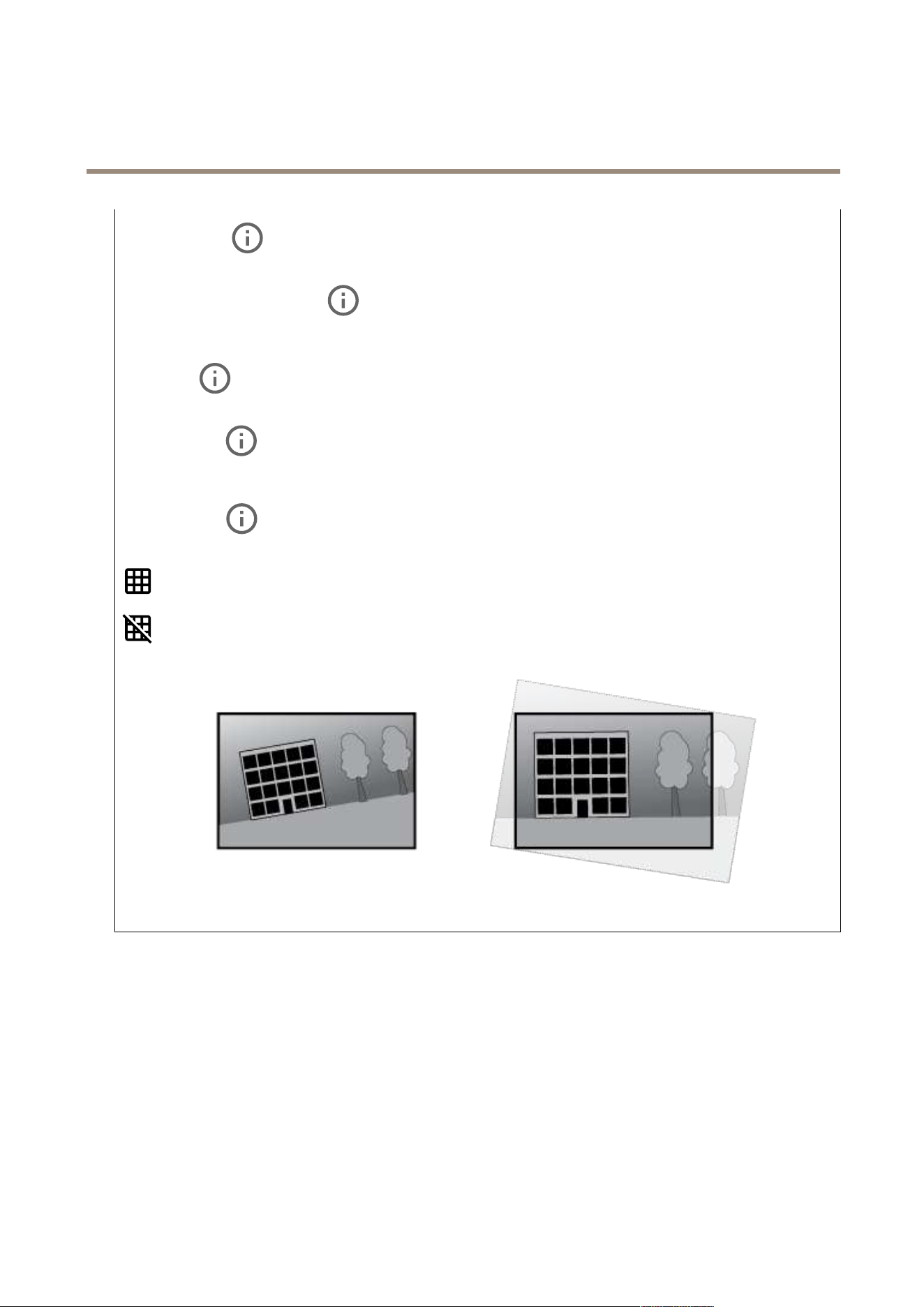
Straighten image
: Turn on and use the slider to straighten the image horizontally by rotating and cropping it digitally. The
functionality is useful when it’s not possible to mount the camera exactly level. Ideally, straighten the image during installation.
: Click to show a supporting grid in the image.
: Click to hide the grid.
The image before and after it has been straightened.
Image
Appearance
39
AXIS P1465-LE-3 License Plate Verifier Kit
The device interface
Scene prole : Select a scene prole that suits your surveillance scenario. A scene prole optimizes image settings,
including color level, brightness, sharpness, contrast, and local contrast, for a specic environment or purpose.
• Forensic: Suitable for surveillance purposes.
• Indoor
: Suitable for indoor environments.
• Outdoor
: Suitable for outdoor environments.
• Vivid: Useful for demonstration purposes.
• Trafc overview: Suitable for vehicle trafc monitoring.
Saturation: Use the slider to adjust the color intensity. You can for example get a grayscale image.
Contrast: Use the slider to adjust the difference between light and dark.
Brightness: Use the slider to adjust the light intensity. This can make objects easier to see. Brightness is applied after image
capture, and doesn’t affect the information in the image. To get more details from a dark area, it’s usually better to increase
gain or exposure time.
Sharpness: Use the slider to make objects in the image appear sharper by adjusting the edge contrast. If you increase the
sharpness, it may increase the bitrate and the amount of storage space needed as well.
Wide dynamic range
40

AXIS P1465-LE-3 License Plate Verifier Kit
The device interface
WDR : Turn on to make both bright and dark areas of the image visible.
Local contrast : Use the slider to adjust the contrast of the image. A higher value makes the contrast higher between
dark and light areas.
Tone mapping
: Use the slider to adjust the amount of tone mapping that is applied to the image. If the value is set to
zero only the standard gamma correction is applied, while a higher value increases the visibility of the darkest and brightest
parts in the image.
White balance
When the camera detects the color temperature of the incoming light, it can adjust the image to make the colors look more
natural. If this is not sufcient, you can select a suitable light source from the list.
The automatic white balance setting reduces the risk of color icker by adapting to changes gradually. If the lighting changes, or
when the camera is rst started, it can take up to 30 seconds to adapt to the new light source. If there is more than one type
of light source in a scene, that is they differ in color temperature, the dominating light source acts as a reference for the
automatic white balance algorithm. This behavior can be overridden by choosing a xed white balance setting that matches
the light source you want to use as a reference.
Light environment:
• Automatic: Automatic identication and compensation for the light source color. This is the recommended setting
which can be used in most situations.
• Automatic – outdoors
: Automatic identication and compensation for the light source color. This is the
recommended setting which can be used in most outdoor situations.
• Custom – indoors
: Fixed color adjustment for a room with some articial light other than uorescent lighting
and good for a normal color temperature around 2800 K.
• Custom – outdoors
: Fixed color adjustment for sunny weather conditions with a color temperature around
5500 K.
• Fixed – uorescent 1: Fixed color adjustment for uorescent lighting with a color temperature around 4000 K.
• Fixed – uorescent 2: Fixed color adjustment for uorescent lighting with a color temperature around 3000 K.
• Fixed – indoors: Fixed color adjustment for a room with some articial light other than uorescent lighting and
good for a normal color temperature around 2800 K.
• Fixed – outdoors 1: Fixed color adjustment for sunny weather conditions with a color temperature around 5500 K.
• Fixed – outdoors 2: Fixed color adjustment for cloudy weather condition with a color temperature around 6500 K.
• Street light – mercury
: Fixed color adjustment for ultraviolet emission in mercury vapor lights common
in street lighting.
• Street light – sodium
: Fixed color adjustment that compensates for the yellow orange color of sodium vapor
lights common in street lighting.
• Hold current: Keep the current settings and do not compensate for light changes.
• Manual
: Fix the white balance with the help of a white object. Drag the circle to an object that you want
the camera to interpret as white in the live view image. Use the Red balance and Blue balance sliders to adjust the
white balance manually.
Day-night mode
41

AXIS P1465-LE-3 License Plate Verifier Kit
The device interface
IR-cut lter:
• Auto: Select to automatically turn on and off the IR-cut lter. When the camera is in day mode, the IR-cut lter
is turned on and blocks incoming infrared light, and when in night mode, the IR-cut lter is turned off and the
camera’s light sensitivity increases.
• On: Select to turn on the IR-cut lter. The image is in color, but with reduced light sensitivity.
• Off: Select to turn off the IR-cut lter. The image is in black and white for increased light sensitivity.
Threshold: Use the slider to adjust the light threshold where the camera changes from day mode to night mode.
• Move the slider towards Bright to decrease the threshold for the IR-cut lter. The camera changes to night mode
earlier.
• Move the slider towards Dark to increase the threshold for the IR-cut lter. The camera changes to night mode later.
IR light
If your device doesn’t have built-in illumination, these controls are only available when you have connected a supporting Axis
accessory.
Allow illumination: Turn on to let the camera use the built-in light in night mode.
Synchronize illumination: Turn on to automatically synchronize the illumination with the surrounding light. The synchronization
between day and night only works if the IR-cut lter is set to Auto or Off.
Automatic illumination angle
: Turn on to use the automatic illumination angle.
Illumination angle : Use the slider to manually set the illumination angle, for example if the angle needs to be different
from the camera’s angle of view. If the camera has a wide angle of view, you can set the illumination angle to a narrower angle,
which equals a greater tele position. This will result in dark corners in the image.
IR wavelength
: Select the desired wavelength for the IR light.
White light
Allow illumination : Turn on to let the camera use white light in night mode.
Synchronize illumination
: Turn on to automatically synchronize the white light with the surrounding light.
Exposure
Exposure mode: Select an exposure mode to reduce rapidly changing irregular effects in the image, for example icker produced
by different types of light sources. We recommend you to use the automatic exposure mode, or the same frequency as your
power network.
• Automatic: The camera adjusts the aperture, gain and shutter automatically.
• Automatic aperture
: The camera adjusts the aperture and gain automatically. The shutter is xed.
• Automatic shutter
: The camera adjusts the shutter and gain automatically. The aperture is xed.
• Hold current: Locks the current exposure settings.
• Flicker-free
: The camera adjusts the aperture and gain automatically, and uses only the following shutter
speeds: 1/50 s (50 Hz) and 1/60 s (60 Hz).
• Flicker-free 50 Hz
: The camera adjusts the aperture and gain automatically, and uses the shutter speed 1/50 s.
42

AXIS P1465-LE-3 License Plate Verifier Kit
The device interface
• Flicker-free 60 Hz : The camera adjusts the aperture and gain automatically, and uses the shutter speed 1/60 s.
• Flicker-reduced
: This is the same as icker-free, but the camera might use shutter speeds faster than
1/100 s (50 Hz) and 1/120 s (60 Hz) for brighter scenes.
• Flicker-reduced 50 Hz
: This is the same as icker-free, but the camera might use shutter speeds faster
than 1/100 s for brighter scenes.
• Flicker-reduced 60 Hz
: This is the same as icker-free, but the camera might use shutter speeds faster
than 1/120 s for brighter scenes.
• Manual
: The aperture, gain and shutter are xed.
Exposure zone: Use exposure zones to optimize the exposure in a selected part of the scene, for example, the area in front
of an entrance door.
Note
The exposure zones are related to the original image (unrotated), and the names of the zones apply to the original image.
This means, for example, that if the video stream is rotated 90°, then the Upper zone becomes the Right zone in the
stream, and Left becomes Lower.
• Automatic: Suitable for most situations.
• Center: Uses a xed area in the center of the image to calculate the exposure. The area has a xed size and
position in the live view.
• Full
: Uses the entire live view to calculate the exposure.
• Upper
: Uses an area with a xed size and position in the upper part of the image to calculate the exposure.
• Lower
: Uses an area with a xed size and position in the lower part of the image to calculate the exposure.
• Left
: Uses an area with a xed size and position in the left part of the image to calculate the exposure.
• Right
: Uses an area with a xed size and position in the right part of the image to calculate the exposure.
• Spot: Uses an area with a xed size and position in the live view to calculate the exposure.
• Custom: Uses an area in the live view to calculate the exposure. You can adjust the size and position of the area.
Max shutter: Select the shutter speed to provide the best image. Low shutter speeds (longer exposure) might cause motion blur
when there is movement, and a too high shutter speed might affect the image quality. Max shutter works with max gain to
improve the image.
Max gain: Select the suitable max gain. If you increase the max gain, it improves the visible level of detail in dark images, but
also increases the noise level. More noise can also result in increased use of bandwidth and storage. If you set the max gain
to a high value, images can differ a lot if the light conditions are very different from day to night. Max gain works with max
shutter to improve the image.
Motion-adaptive exposure
: Select to reduce motion blur in low-light conditions.
Blur-noise trade-off: Use the slider to adjust the priority between motion blur and noise. If you want to prioritize low bandwidth
and have less noise at the expense of details in moving objects, move the slider towards Low noise. If you want to prioritize the
preservation of details in moving objects at the expense of noise and bandwidth, move the slider towards Low motion blur.
Note
You can change the exposure either by adjusting the exposure time or by adjusting the gain. If you increase the exposure
time, it results in more motion blur, and if you increase the gain it results in more noise. If you adjust the Blur-noise
trade-off towards Low noise, the automatic exposure will prioritize longer exposure times over increasing gain, and the
opposite if you adjust the trade-off towards Low motion blur. Both the gain and exposure time will eventually reach
their maximum values in low-light conditions, regardless of the priority set.
43
AXIS P1465-LE-3 License Plate Verifier Kit
The device interface
Lock aperture : Turn on to keep the aperture size set by the Aperture slider. Turn off to allow the camera to automatically
adjust the aperture size. You can, for example, lock the aperture for scenes with permanent light conditions.
Aperture
: Use the slider to adjust the aperture size, that is, how much light passes through the lens. To allow more light
to enter the sensor and thereby produce a brighter image in low-light conditions, move the slider towards Open. An open aperture
also reduces the depth of eld, which means that objects close to or far from the camera can appear unfocused. To allow more of
the image to be in focus, move the slider towards Closed.
Exposure level: Use the slider to adjust the image exposure.
Defog
: Turn on to detect the effects of foggy weather and automatically remove them for a clearer image.
Note
We recommend you not to turn on Defog in scenes with low contrast, large light level variations, or when the autofocus is
slightly off. This can affect the image quality, for example, by increasing the contrast. Furthermore, too much light can
negatively impact the image quality when defog is active.
Optics
Temperature compensation: Turn on if you want the focus position to be corrected based on the temperature in the optics.
IR compensation : Turn on if you want the focus position to be corrected when IR-cut lter is off and when there is IR light.
Calibrate zoom and focus: Click to reset the optics and the zoom and focus settings to the factory default position. You need to
do this if the optics have lost calibration during transport, or if the device has been exposed to extreme vibrations.
Stream
General
Resolution: Select the image resolution suitable for the surveillance scene. A higher resolution increases bandwidth and storage.
Frame rate: To avoid bandwidth problems on the network or reduce storage size, you can limit the frame rate to a xed amount.
If you leave the frame rate at zero, the frame rate is kept at the highest possible rate under the current conditions. A higher
frame rate requires more bandwidth and storage capacity.
Compression: Use the slider to adjust the image compression. High compression results in a lower bitrate and lower image quality.
Low compression improves the image quality, but uses more bandwidth and storage when you record.
Signed video
: Turn on to add the signed video feature to the video. Signed video protects the video from tampering by
adding cryptographic signatures to the video.
H.26x encoding
44

AXIS P1465-LE-3 License Plate Verifier Kit
The device interface
Zipstream: A bitrate reduction technology, optimized for video surveillance, that reduces the average bitrate in an H.264 or H.265
stream in real time. Axis Zipstream applies a high bitrate in scenes where there are multiple regions of interest, for example in
scenes with moving objects. When the scene is more static, Zipstream applies a lower bitrate, and thereby reduces the required
storage. To learn more, see Reducing the bit rate with Axis Zipstream
Select the desired level of bitrate reduction:
• Off: No bitrate reduction.
• Low: No visible quality degradation in most scenes. This is the default option and it can be used in all types
of scenes to reduce the bitrate.
• Medium: Visible effects in some scenes through less noise and a slightly lower level of detail in regions of lower
interest, for example where there’s no movement.
• High: Visible effects in some scenes through less noise and a lower level of detail in regions of lower interest,
for example where there’s no movement. We recommend this level for cloud-connected devices and devices that
use local storage.
• Higher: Visible effects in some scenes through less noise and a lower level of detail in regions of lower interest,
for example where there’s no movement.
• Extreme: Visible effects in most scenes. The bitrate is optimized for smallest possible storage.
Optimize for storage: Optimize settings for storing the stream by minimizing the bitrate while maintaining quality. The
optimization is not applied to the stream shown in the web client. Turning on Optimize for storage also turns on Dynamic GOP.
Dynamic FPS (frames per second): Turn on to allow the bandwidth to vary based on the level of activity in the scene. More
activity requires more bandwidth.
Lower limit
: Enter a value to adjust the frame rate between minimal fps and the stream default fps based on scene
motion. We recommend you to use lower limit in scenes with very little motion, where the fps could drop to 1 or lower.
Dynamic GOP (Group of Pictures): Turn on to dynamically adjust the interval between I-frames based on the level of activity
in the scene.
Upper limit
: Enter a maximum GOP length, that is, the maximum number of P-frames between two I-frames. An I-frame
is a self-contained image frame that is independent of other frames.
P-frames: A P-frame is a predicted image that shows only the changes in the image from the previous frame. Enter the desired
number of P-frames. The higher the number, the less bandwidth is required. However, if there are network congestion, there could
be a noticeable deterioration in the video quality.
Bitrate control:
• Average: Select to automatically adjust the bitrate over a longer time period and provide the best possible image
quality based on the available storage.
-
Click to calculate the target bitrate based on available storage, retention time, and bitrate limit.
- Target bitrate: Enter desired target bitrate.
- Retention time: Enter the number of days to keep the recordings.
- Storage: Shows the estimated storage that can be used for the stream.
- Maximum bitrate: Turn on to set a bitrate limit.
- Bitrate limit
: Enter a bitrate limit that is higher than the target bitrate.
• Maximum: Select to set a maximum instant bitrate of the stream based on your network bandwidth.
- Maximum: Enter the maximum bitrate.
• Variable: Select to allow the bitrate to vary based on the level of activity in the scene. More activity requires more
bandwidth. We recommend this option for most situations.
Orientation
Mirror: Turn on to mirror the image.
Audio
45
AXIS P1465-LE-3 License Plate Verifier Kit
The device interface
Include: Turn on to use audio in the video stream.
Source : Select what audio source to use.
Stereo : Turn on to include built-in audio as well as audio from an external microphone.
Overlays
: Click to add an overlay. Select the type of overlay from the dropdown list:
• Text: Select to show a text that is integrated in the live view image and visible in all views, recordings and snapshots.
You can enter your own text, and you can also include pre-congured modiers to automatically show for example
time, date, frame rate.
-
: Click to add the date modier %F to show yyyy-mm-dd.
-
: Click to add the time modier %X to show hh:mm:ss (24-hour clock).
- Modiers: Click to select any of the modiers shown in the list to add them to the text box. For example,
%a shows the day of the week.
- Size: Select the desired font size.
- Appearance: Select the text color and background color, for example, white text on a black background
(default).
-
: Select the position of the overlay in the image.
• Image: Select to show a static image superimposed over the video stream. You can use .bmp, .png, .jpeg, or .svg les.
To upload an image, click Images. Before you upload an image, you can choose to:
- Scale with resolution: Select to automatically scale the overlay image to t the video resolution.
- Use transparency: Select and enter the RGB hexadecimal value for that color. Use the format RRGGBB.
Examples of hexadecimal values: FFFFFF for white, 000000 for black, FF00000 for red, 6633FF for blue, and
669900 for green. Only for .bmp images.
• Streaming indicator
: Select to show an animation superimposed over the video stream. The animation
indicates that the video stream is live, even if the scene doesn’t contain any motion.
- Appearance: Select the animation color and background color, for example, red animation on a transparent
background (default).
- Size: Select the desired font size.
-
: Select the position of the overlay in the image.
View areas
: Click to create a view area.
Click the view area to access settings.
Name: Enter a name for the view area. The maximum length is 64 characters.
Aspect ratio: Select desired aspect ratio. The resolution adjusts automatically.
PTZ: Turn on to use pan, tilt, and zoom functionality in the view area.
46

AXIS P1465-LE-3 License Plate Verifier Kit
The device interface
Privacy masks
: Click to create a new privacy mask. The maximum number of masks depend on the complexity of all masks combined.
Each mask can have maximum 10 anchor points.
Privacy masks: Click to change the color of all privacy masks, or to delete all privacy masks permanently.
Cell size: If you choose mosaic color, the privacy masks appear as pixilated patterns. Use the slider to change the size of the pixels.
Mask x: Click to rename, disable, or permanently delete the mask.
Audio
Overview
Locate device: Click to play a sound that helps you identify the speaker. For some products, a LED will ash on the device.
Calibrate
: Click to calibrate the speaker.
Launch AXIS Audio Manager Edge: Click to launch the application.
Device settings
Input: Turn on or off audio input. Shows the type of input.
Allow stream extraction : Turn on to allow stream extraction.
Input type : Select the type of input, for instance if it’s internal microphone or line-in.
Power type
: Select power type for your input.
Apply changes
: Click to apply your selection.
Separate gain controls
: Turn on to adjust the gain separately for the different input types.
Automatic gain control : Turn on to dynamically adapt the gain to changes in the sound.
Gain: Use the slider to change the gain. Click the microphone icon to mute or unmute.
Output : Shows the type of output.
Gain: Use the slider to change the gain. Click the speaker icon to mute or unmute.
47
AXIS P1465-LE-3 License Plate Verifier Kit
The device interface
Stream
Encoding: Select the encoding to use for the input source streaming. You can only choose encoding if audio input is turned on. If
audio input is turned off, click Enable audio input to turn it on.
Recordings
Click to lter the recordings.
From: Show recordings done after a certain point in time.
To: Show recordings up until a certain point in time.
Source
: Show recordings based on source.
Event: Show recordings based on events.
Storage: Show recordings based on storage type.
Ongoing recordings: Show all ongoing recordings on the camera.
Select to start a recording on the camera.
Choose which storage device to save to.
Select to stop a recording on the camera.
Triggered recordings will end both when manually stopped and when the camera is shut down.
Continuous recordings will continue until manually stopped. Even if the camera is shut down, the recording will continue
when the camera starts up again.
Click to play the recording.
Click to stop playing the recording.
Click to show more information and options about the recording.
Set export range: If you only want to export part of the recording, enter from when to when.
Click to delete the recording.
Export: Click to export (part of) the recording.
48

AXIS P1465-LE-3 License Plate Verifier Kit
The device interface
Apps
Add app: Click to install a new app.
Find more apps: Click to go to an overview page of Axis apps.
Allow unsigned apps: Turn on to allow installation of unsigned apps.
Note
The device’s performance might be affected if you run several apps at the same time.
Use the switch next to the app name to start or stop the app.
Open: Click to access the app’s settings. The available settings depend on the application. Some applications don’t have any
settings.
The context menu can contain one or more of the following options:
• Open-source license: Click to view information about open-source licenses used in the app.
• App log: Click to view a log of the app events. The log is helpful when you contact support.
• Activate license with a key: If the app requires a license, you need to activate it. Use this option if your device
doesn’t have internet access.
If you don’t have a license key, go to axis.com/products/analytics. You need a license code and the Axis product serial
number to generate a license key.
• Activate license automatically: If the app requires a license, you need to activate it. Use this option if your device has
internet access. You need a license code to activate the license.
• Deactivate the license: Deactivate the license to use it in another device. If you deactivate the license, you also
remove it from the device. To deactivate the license requires internet access.
• Settings: Congure the parameters.
• Delete: Delete the app permanently from the device. If you don’t deactivate the license rst, it remains active.
System
Date and time
The time format depends on the web browser’s language settings.
Note
We recommend you to synchronize the device’s date and time with an NTP server.
Synchronization: Select an option for synchronizing the device’s date and time.
• Automatic date and time (manual NTS KE servers): Synchronize with the secure NTP key establishment servers
connected to the DHCP server.
- Manual NTS KE servers: Enter the IP address of one or two NTP servers. When you use two NTP servers,
the device synchronizes and adapts its time based on input from both.
• Automatic date and time (NTP servers using DHCP): Synchronize with the NTP servers connected to the DHCP server.
- Fallback NTP servers: Enter the IP address of one or two fallback servers.
• Automatic date and time (manual NTP servers): Synchronize with NTP servers of your choice.
- Manual NTP servers: Enter the IP address of one or two NTP servers. When you use two NTP servers, the
device synchronizes and adapts its time based on input from both.
• Custom date and time: Manually set the date and time. Click Get from system to fetch the date and time settings
once from your computer or mobile device.
Time zone: Select which time zone to use. Time will be automatically adjusted for daylight saving time and standard time.
49

AXIS P1465-LE-3 License Plate Verifier Kit
The device interface
Note
The system uses the date and time settings in all recordings, logs and system settings.
Network
IPv4
Assign IPv4 automatically: Select to let the network router assign an IP address to the device automatically. We recommend
automatic IP (DHCP) for most networks.
IP address: Enter a unique IP address for the device. Static IP addresses can be assigned at random within isolated networks,
provided that each address is unique. To avoid conicts, we recommend you to contact your network administrator before you
assign a static IP address.
Subnet mask: Enter the subnet mask to dene what addresses are inside the local area network. Any address outside the local
area network goes through the router.
Router: Enter the IP address of the default router (gateway) used to connect devices that are attached to different networks and
network segments.
IPv6
Assign IPv6 automatically: Select to turn on IPv6 and to let the network router assign an IP address to the device automatically.
Hostname
Assign hostname automatically: Select to let the network router assign a hostname to the device automatically.
Hostname: Enter the hostname manually to use as an alternative way of accessing the device. The Hostname is used in the server
report and in the system log. Allowed characters are A–Z, a–z, 0–9 and -.
DNS servers
Assign DNS automatically: Select to let the network router assign search domains and DNS server addresses to the device
automatically. We recommend automatic DNS (DHCP) for most networks.
Search domains: When you use a hostname that is not fully qualied, click Add search domain and enter a domain in which to
search for the hostname used by the device.
DNS servers: Click Add DNS server and enter the IP address of the DNS server. This provides the translation of hostnames to IP
addresses on your network.
HTTP and HTTPS
Allow access through: Select if a user is allowed to connect to the device through the HTTP, HTTPS, or both HTTP and HTTPS
protocols.
HTTPS is a protocol that provides encryption for page requests from users and for the pages returned by the web server. The
encrypted exchange of information is governed by the use of an HTTPS certicate, which guarantees the authenticity of the server.
To use HTTPS on the device, you must install an HTTPS certicate. Go to System > Security to create and install certicates.
Note
If you view encrypted web pages through HTTPS, you might experience a drop in performance, especially when you
request a page for the rst time.
HTTP port: Enter the HTTP port to use. Port 80 or any port in the range 1024-65535 are allowed. If you are logged in as an
administrator, you can also enter any port in the range 1-1023. If you use a port in this range, you get a warning.
50

AXIS P1465-LE-3 License Plate Verifier Kit
The device interface
HTTPS port: Enter the HTTPS port to use. Port 443 or any port in the range 1024-65535 are allowed. If you are logged in as an
administrator, you can also enter any port in the range 1-1023. If you use a port in this range, you get a warning.
Certicate: Select a certicate to enable HTTPS for the device.
Network discovery protocols
Bonjour
®
: Turn on to allow automatic discovery on the network.
Bonjour name: Enter a friendly name to be visible on the network. The default name is the device name and MAC address.
UPnP
®
: Turn on to allow automatic discovery on the network.
UPnP name: Enter a friendly name to be visible on the network. The default name is the device name and MAC address.
WS-Discovery: Turn on to allow automatic discovery on the network.
One-click cloud connection
One-click cloud connection (O3C) together with an O3C service provides easy and secure internet access to live and recorded video
from any location. For more information, see axis.com/end-to-end-solutions/hosted-services.
Allow O3C:
• One-click: The default setting. Press and hold the control button on the device to connect to an O3C service over the
internet. You need to register the device with the O3C service within 24 hours after you press the control button.
Otherwise, the device disconnects from the O3C service. Once you have registered the device, Always is enabled and
the device stays connected to the O3C service.
• Always: The device constantly attempts to connect to an O3C service over the internet. Once you have registered the
device, it stays connected to the O3C service. Use this option if the control button on the device is out of reach.
• No: Disables the O3C service.
Proxy settings: If needed, enter the proxy settings to connect to the proxy server.
Host: Enter the proxy server’s address.
Port: Enter the port number used for access.
Login and Password: If needed, enter username and password for the proxy server.
Authentication method:
• Basic: This method is the most compatible authentication scheme for HTTP. It’s less secure than the Digest method
because it sends the username and password unencrypted to the server.
• Digest: This method is more secure because it always transfers the password encrypted across the network.
• Auto: This option lets the device select the authentication method depending on the supported methods. It prioritizes
the Digest method over the Basic method.
Owner authentication key (OAK): Click Get key to fetch the owner authentication key. This is only possible if the device is
connected to the internet without a rewall or proxy.
SNMP
51

AXIS P1465-LE-3 License Plate Verifier Kit
The device interface
The Simple Network Management Protocol (SNMP) allows remote management of network devices.
SNMP: Select the version of SNMP to use.
• v1 and v2c:
- Read community: Enter the community name that has read-only access to all supported SNMP objects. The
default value is public.
- Write community: Enter the community name that has read/write access to all supported SNMP objects
(except read-only objects). The default value is write.
- Activate traps: Turn on to activate trap reporting. The device uses traps to send messages for important
events or status changes to a management system. In the device interface, you can set up traps for SNMP v1
and v2c. Traps are automatically turned off if you change to SNMP v3 or turn off SNMP. If you use SNMP v3,
you can set up traps through the SNMP v3 management application.
- Trap address: Enter the IP address or host name of the management server.
- Trap community: Enter the community to use when the device sends a trap message to the management
system.
- Traps:
- Cold start: Sends a trap message when the device starts.
- Warm start: Sends a trap message when you change an SNMP setting.
- Link up: Sends a trap message when a link changes from down to up.
- Authentication failed: Sends a trap message when an authentication attempt fails.
Note
All Axis Video MIB traps are enabled when you turn on SNMP v1 and v2c traps. For more information, see
AXIS OS Portal > SNMP.
• v3: SNMP v3 is a more secure version, which provides encryption and secure passwords. To use SNMP v3, we
recommend you to activate HTTPS, as the password is then sent through HTTPS. This also prevents unauthorized
parties to access unencrypted SNMP v1 and v2c traps. If you use SNMP v3, you can set up traps through the SNMP v3
management application.
- Password for the account “initial”: Enter the SNMP password for the account named “initial”. Although the
password can be sent without activating HTTPS, we don’t recommend it. The SNMP v3 password can only
be set once, and preferably only when HTTPS is enabled. Once the password is set, the password eld is no
longer displayed. To set the password again, you must reset the device to factory default settings.
Security
Certicates
Certicates are used to authenticate devices on a network. The device supports two types of certicates:
• Client/server certicates
A client/server certicate validates the device’s identity, and can be self-signed or issued by a Certicate Authority (CA).
A self-signed certicate offers limited protection and can be used before a CA-issued certicate has been obtained.
• CA certicates
You can use a CA certicate to authenticate a peer certicate, for example to validate the identity of an authentication
server when the device connects to a network protected by IEEE 802.1X. The device has several pre-installed CA
certicates.
These formats are supported:
• Certicate formats: .PEM, .CER, and .PFX
• Private key formats: PKCS#1 and PKCS#12
Important
If you reset the device to factory default, all certicates are deleted. Any pre-installed CA certicates are reinstalled.
Filter the certicates in the list.
Add certicate : Click to add a certicate.
52
AXIS P1465-LE-3 License Plate Verifier Kit
The device interface
The context menu contains:
• Certicate information: View an installed certicate’s properties.
• Delete certicate: Delete the certicate.
• Create certicate signing request: Create a certicate signing request to send to a registration authority to apply
for a digital identity certicate.
IEEE 802.1x
IEEE 802.1x is an IEEE standard for port-based network admission control providing secure authentication of wired and wireless
network devices. IEEE 802.1x is based on EAP (Extensible Authentication Protocol).
To access a network protected by IEEE 802.1x, network devices must authenticate themselves. The authentication is performed by
an authentication server, typically a RADIUS server (for example FreeRADIUS and Microsoft Internet Authentication Server).
Certicates
When congured without a CA certicate, server certicate validation is disabled and the device tries to authenticate itself
regardless of what network it is connected to.
When using a certicate, in Axis' implementation, the device and the authentication server authenticate themselves with digital
certicates using EAP-TLS (Extensible Authentication Protocol - Transport Layer Security).
To allow the device to access a network protected through certicates, a signed client certicate must be installed on the device.
Client certicate: Select a client certicate to use IEEE 802.1x. The authentication server uses the certicate to validate the
client’s identity.
CA certicate: Select a CA certicate to validate the authentication server’s identity. When no certicate is selected, the device
tries to authenticate itself regardless of what network it is connected to.
EAP identity: Enter the user identity associated with the client certicate.
EAPOL version: Select the EAPOL version that is used in the network switch.
Use IEEE 802.1x: Select to use the IEEE 802.1x protocol.
Prevent brute-force attacks
Blocking: Turn on to block brute-force attacks. A brute-force attack uses trial-and-error to guess login info or encryption keys.
Blocking period: Enter the number of seconds to block a brute-force attack.
Blocking conditions: Enter the number of authentication failures allowed per second before the block starts. You can set the
number of failures allowed both on page level and device level.
IP address lter
Use lter: Select to lter which IP addresses that are allowed to access the device.
Policy: Choose whether to Allow access or Deny access for certain IP addresses.
Addresses: Enter the IP numbers that are either allowed or denied access to the device. You can also use the CIDR format.
Custom-signed rmware certicate
53
AXIS P1465-LE-3 License Plate Verifier Kit
The device interface
To install test rmware or other custom rmware from Axis on the device, you need a custom-signed rmware certicate. The
certicate veries that the rmware is approved by both the device owner and Axis. The rmware can only run on a specic
device which is identied by its unique serial number and chip ID. Custom-signed rmware certicates can only be created
by Axis, since Axis holds the key to sign them.
Click Install to install the certicate. You need to install the certicate before you install the rmware.
Users
Add user: Click to add a new user. You can add up to 100 users.
Username: Enter a unique username.
New password: Enter a password for the user. Passwords must be 1 to 64 characters long. Only ASCII printable characters (code
32 to 126) are allowed in the password, for example letters, numbers, punctuation, and some symbols.
Repeat password: Enter the same password again.
Role:
• Administrator: Has full access to all settings. Administrators can also add, update, and remove other users.
• Operator: Has access to all settings except:
- All System settings.
- Adding apps.
• Viewer: Has access to:
- Watch and take snapshots of a video stream.
- Watch and export recordings.
- With PTZ user access: pan, tilt, and zoom.
The context menu contains:
Update user: Edit the user’s properties.
Delete user: Delete the user. You can’t delete the root user.
Anonymous users
Allow anonymous viewers: Turn on to allow anyone to access the device as a viewer without having to log in with a user account.
Allow anonymous PTZ operators: Turn on to allow anonymous users to pan, tilt, and zoom the image.
Events
Rules
A rule denes the conditions that must be met for the product to perform an action. The list shows all the currently congured
rules in the product.
Note
You can create up to 256 action rules.
Add a rule: Click to create a rule.
Name: Enter a name for the rule.
54

AXIS P1465-LE-3 License Plate Verifier Kit
The device interface
Wait between actions: Enter the minimum time (hh:mm:ss) that must pass between rule activations. It is useful if the rule is
activated by for example day-night mode conditions, to avoid that small light changes during sunrise and sunset activate
the rule repeatedly.
Condition: Select a condition from the list. A condition must be met for the device to perform an action. If multiple
conditions are dened, all of them must be met to trigger the action. For information about specic conditions, see
Get started with rules for events.
Use this condition as a trigger: Select to make this rst condition function only as a starting trigger. It means that once the rule
is activated it remains active for as long as all the other conditions are met, no matter the state of the rst condition. If you don’t
select this option, the rule will simply be active whenever all the conditions are met.
Invert this condition: Select if you want the condition to be the opposite of your selection.
Add a condition: Click to add an additional condition.
Action: Select an action from the list and enter its required information. For information about specic actions, see
Get started with rules for events.
Your product may have some of the following pre-congured rules:
Front-facing LED Activation: LiveStream: When the microphone is turned on and a live stream is received, then the front-facing
LED on the audio device will turn green.
Front-facing LED Activation: Recording : When the microphone is turned on and a recording is ongoing, then the front-facing
LED on the audio device will turn green.
Front-facing LED Activation: SIP : When the microphone is turned on and a SIP call is active, then the front-facing LED on the
audio device will turn green. SIP must be enabled on the audio device before this event can be triggered.
Pre-announcement tone: Play tone on incoming call: When a SIP call is made to the audio device, then a pre-dened audio clip
is played. SIP must be enabled for the audio device. For the SIP caller to hear a ring tone while the audio clip is played, the SIP
account for the audio device must be congured to not answer the call automatically.
Pre-announcement tone: Answer call after incoming call-tone: When the audio clip has ended, the incoming SIP-call is
answered. SIP must be enabled for the audio device.
Loud ringer : When a SIP call is made to the audio device, a pre-dened audio clip is played as long as the rule is active. SIP
must be enabled for the audio device.
Recipients
You can set up your device to notify recipients about events or send les. The list shows all the recipients currently congured in
the product, along with information about their conguration.
Note
You can create up to 20 recipients.
Add a recipient: Click to add a recipient.
Name: Enter a name for the recipient.
Type: Select from the list:
• FTP
- Host: Enter the server's IP address or hostname. If you enter a hostname, make sure that a DNS server is
specied under System > Network > IPv4 and IPv6.
- Port: Enter the port number used by the FTP server. The default is 21.
55

AXIS P1465-LE-3 License Plate Verifier Kit
The device interface
- Folder: Enter the path to the directory where you want to store les. If this directory doesn’t already exist
on the FTP server, you will get an error message when uploading les.
- Username: Enter the username for the login.
- Password: Enter the password for the login.
- Use temporary le name: Select to upload les with temporary, automatically generated lenames. The
les get renamed to the desired names when the upload completes. If the upload is aborted/interrupted,
you don’t get any corrupt les. However, you probably still get the temporary les. This way you know that
all les that have the desired name, are correct.
- Use passive FTP: Under normal circumstances the product simply requests the target FTP server to open the
data connection. The device actively initiates both the FTP control and data connections to the target server.
This is normally needed if there is a rewall between the device and the target FTP server.
• HTTP
- URL: Enter the network address to the HTTP server and the script that will handle the request. For example:
http://192.168.254.10/cgi-bin/notify.cgi.
- Username: Enter the username for the login.
- Password: Enter the password for the login.
- Proxy: Turn on and enter the required information if a proxy server must be passed to connect to the HTTP
server.
• HTTPS
- URL: Enter the network address to the HTTPS server and the script that will handle the request. For example:
https://192.168.254.10/cgi-bin/notify.cgi.
- Validate server certicate: Select to validate the certicate that was created by HTTPS server.
- Username: Enter the username for the login.
- Password: Enter the password for the login.
- Proxy: Turn on and enter the required information if a proxy server must be passed to connect to the HTTPS
server.
• Network storage
You can add network storage such as a NAS (Network Attached Storage) and use it as a recipient to store les.
The les are stored in the Matroska (MKV) le format.
- Host: Enter the IP address or hostname for the network storage.
- Share: Enter the name of the share on the host.
- Folder: Enter the path to the directory where you want to store les.
- Username: Enter the username for the login.
- Password: Enter the password for the login.
• SFTP
- Host: Enter the server's IP address or hostname. If you enter a hostname, make sure that a DNS server is
specied under System > Network > IPv4 and IPv6.
- Port: Enter the port number used by the SFTP server. The default is 22.
- Folder: Enter the path to the directory where you want to store les. If this directory doesn’t already exist on
the SFTP server, you will get an error message when uploading les.
- Username: Enter the username for the login.
- Password: Enter the password for the login.
- SSH host public key type (MD5): Enter the ngerprint of the remote host’s public key (a 32-digit
hexadecimal string). The SFTP client supports SFTP servers using SSH-2 with RSA, DSA, ECDSA, and ED25519
host key types. RSA is the preferred method during negotiation, followed by ECDSA, ED25519, and DSA. Make
sure to enter the right MD5 host key that is used by your SFTP server. While the Axis device supports both
MD5 and SHA-256 hash keys, we recommend using SHA-256 due to stronger security over MD5. For more
information on how to congure an SFTP server with an Axis device, go to the AXIS OS Portal.
- SSH host public key type (SHA256): Enter the ngerprint of the remote host’s public key (a 43-digit Base64
encoded string). The SFTP client supports SFTP servers using SSH-2 with RSA, DSA, ECDSA, and ED25519 host
key types. RSA is the preferred method during negotiation, followed by ECDSA, ED25519, and DSA. Make
sure to enter the right MD5 host key that is used by your SFTP server. While the Axis device supports both
MD5 and SHA-256 hash keys, we recommend using SHA-256 due to stronger security over MD5. For more
information on how to congure an SFTP server with an Axis device, go to the AXIS OS Portal.
- Use temporary le name: Select to upload les with temporary, automatically generated lenames. The
les get renamed to the desired names when the upload completes. If the upload is aborted/interrupted,
you don’t get any corrupt les. However, you probably still get the temporary les. This way you know that
all les that have the desired name, are correct.
• SIP or VMS
:
SIP: Select to make a SIP call.
VMS: Select to make a VMS call.
56

AXIS P1465-LE-3 License Plate Verifier Kit
The device interface
- From SIP account: Select from the list.
- To SIP address: Enter the SIP address.
- Test: Click to test that your call settings works.
• Email
- Send email to: Enter the email address to send emails to. To enter multiple addresses, use commas to
separate them.
- Send email from: Enter the email address of the sending server.
- Username: Enter the username for the mail server. Leave this eld empty if the mail server does not
require authentication.
- Password: Enter the password for the mail server. Leave this eld empty if the mail server does not require
authentication.
- Email server (SMTP): Enter the name of the SMTP server, for example smtp.gmail.com, smtp.mail.yahoo.com.
- Port: Enter the port number for the SMTP server, using values in the range 0-65535. The default value is 587.
- Encryption: To use encryption, select either SSL or TLS.
- Validate server certicate: If you use encryption, select to validate the identity of the device. The certicate
can be self-signed or issued by a Certicate Authority (CA).
- POP authentication: Turn on to enter the name of the POP server, for example pop.gmail.com.
Note
Some email providers have security lters that prevent users from receiving or viewing large amount of
attachments, from receiving scheduled emails and similar. Check the email provider's security policy to avoid
your email account being locked or missing out on your expected emails.
• TCP
- Host: Enter the server's IP address or hostname. If you enter a hostname, make sure that a DNS server is
specied under System > Network > IPv4 and IPv6.
- Port: Enter the port number used to access the server.
Test: Click to test the setup.
The context menu contains:
View recipient: Click to view all the recipient details.
Copy recipient: Click to copy a recipient. When you copy, you can make changes to the new recipient.
Delete recipient: Click to delete the recipient permanently.
Schedules
Schedules and pulses can be used as conditions in rules. The list shows all the schedules and pulses currently congured in the
product, along with information about their conguration.
Add schedule: Click to create a schedule or pulse.
Manual trigger
The manual trigger is used to manually trigger a rule. The manual trigger can for example be used to validate actions during
product installation and conguration.
57

AXIS P1465-LE-3 License Plate Verifier Kit
The device interface
MQTT
MQTT (Message Queuing Telemetry Transport) is a standard messaging protocol for the Internet of Things (IoT). It was designed for
simplied IoT integration and is used in a wide variety of industries to connect remote devices with a small code footprint and
minimal network bandwidth. The MQTT client in Axis device rmware can simplify integration of data and events produced in the
device to systems which are not video management systems (VMS).
Set up the device as an MQTT client. MQTT communication is based on two entities, the clients and the broker. The clients can
send and receive messages. The broker is responsible for routing messages between clients.
You can learn more about MQTT in AXIS OS Portal.
MQTT client
Connect: Turn on or off the MQTT client.
Status: Shows the current status of the MQTT client.
Broker
Host: Enter the hostname or IP address of the MQTT server.
Protocol: Select which protocol to use.
Port: Enter the port number.
• 1883 is the default value for MQTT over TCP
• 8883 is the default value for MQTT over SSL
• 80 is the default value for MQTT over WebSocket
• 443 is the default value for MQTT over WebSocket Secure
Username: Enter the username that the client will use to access the server.
Password: Enter a password for the username.
Client ID: Enter a client ID. The client identier is sent to the server when the client connects to it.
Clean session: Controls the behavior at connection and disconnection time. When selected, the state information is discarded
at connect and disconnect.
Keep alive interval: The keep alive interval enables the client to detect when the server is no longer available without having
to wait for the long TCP/IP timeout.
Timeout: The time interval in seconds to allow a connect to complete. Default value: 60
Device topic prex: Used in the default values for the topic in the connect message and LWT message on the MQTT client tab,
and in the publication conditions on the MQTT publication tab.
Reconnect automatically: Species whether the client should reconnect automatically after a disconnect.
Connect message
Species if a message should be sent out when a connection is established.
Send message: Turn on to send messages.
Use default: Turn off to enter your own default message.
Topic: Enter the topic for the default message.
Payload: Enter the content for the default message.
Retain: Select to keep the state of client on this Topic
QoS: Change the QoS layer for the packet ow.
58

AXIS P1465-LE-3 License Plate Verifier Kit
The device interface
Last Will and Testament message
The Last Will Testament (LWT) lets a client provide a testament along with its credentials when connecting to the broker. If the
client disconnects ungracefully at some point later (maybe because his power source died), it can let the broker deliver a message
to other clients. This LWT message has the same form as an ordinary message and gets routed via the same mechanics.
Send message: Turn on to send messages.
Use default: Turn off to enter your own default message.
Topic: Enter the topic for the default message.
Payload: Enter the content for the default message.
Retain: Select to keep the state of client on this Topic
QoS: Change the QoS layer for the packet ow.
MQTT publication
Use default topic prex: Select to use the default topic prex, that is dened in the device topic prex in the MQTT client tab.
Include topic name: Select to include the topic that describes the condition in the MQTT topic.
Include topic namespaces: Select to include ONVIF topic namespaces in the MQTT topic.
Include serial number: Select to include the device’s serial number in the MQTT payload.
Add condition: Click to add a condition.
Retain: Denes which MQTT messages are sent as retained.
• None: Send all messages as non-retained.
• Property: Send only stateful messages as retained.
• All: Send both stateful and stateless messages as retained.
QoS: Select the desired level for the MQTT publication.
MQTT subscriptions
Add subscription: Click to add a new MQTT subscription.
Subscription lter: Enter the MQTT topic that you want to subscribe to.
Use device topic prex: Add the subscription lter as prex to the MQTT topic.
Subscription type:
• Stateless: Select to convert MQTT messages into a stateless message.
• Stateful: Select to convert MQTT messages into a condition. The payload is used as the state.
QoS: Select the desired level for the MQTT subscription.
Storage
Network storage
59

AXIS P1465-LE-3 License Plate Verifier Kit
The device interface
Add network storage: Click to add a network share where you can save recordings.
• Address: Enter the IP address or host name of the host server, typically a NAS (Network Attached Storage). We
recommend you to congure the host to use a xed IP address (not DHCP since a dynamic IP address can change) or
that you use DNS. Windows SMB/CIFS names are not supported.
• Network share: Enter the name of the shared location on the host server. Several Axis devices can use the same
network share, since each device gets its own folder.
• User: If the server requires a login, enter the username. To log in to a specic domain server, type
DOMAIN\username.
• Password: If the server requires a login, enter the password.
• SMB version: Select the SMB storage protocol version to connect to the NAS. If you select Auto, the device tries
to negotiate one of the secure versions SMB: 3.02, 3.0, or 2.1. Select 1.0 or 2.0 to connect to older NAS that don’t
support higher versions. You can read more about SMB support in Axis devices here.
• Add share even if connection test fails: Select to add the network share even if an error is discovered during the
connection test. The error can be, for example, that you didn’t enter a password even though the server requires one.
Remove network storage: Click to remove the connection to the network share. This removes all settings for the network share.
Write protect: Turn on to stop writing to the network share and protect recordings from being removed. You can’t format a
write-protected network share.
Ignore: Turn on to stop storing recordings on the network share.
Retention time: Select how long to keep recordings, to limit the amount of old recordings or to comply with regulations regarding
data storage. If the network storage becomes full, old recordings are removed before the selected time period has passed.
Tools
• Test connection: Test the connection to the network share.
• Format: Format the network share, for example when you need to quickly erase all data. cifs is the available le
system option.
Click Use tool to activate the selected tool.
Onboard storage
Important
Risk of data loss and corrupted recordings. Do not remove the SD card while the device is running. Unmount the SD
card before you remove it.
Unmount: Click to safely remove the SD card.
Write protect: Turn on to stop writing to the SD card and protect recordings from being removed. You can’t format a
write-protected SD card.
Autoformat: Turn on to automatically format a newly inserted SD card. It formats the le system into ext4.
Ignore: Turn on to stop storing recordings on the SD card. When you ignore the SD card, the device no longer recognizes that the
card exists. The setting is only available for administrators.
Retention time: Select how long to keep recordings, to limit the amount of old recordings or to comply with regulations regarding
data storage. If the SD card becomes full, old recordings are removed before the selected time period has passed.
Tools
• Check: Check for errors on the SD card. This only works for the ext4 le system.
• Repair: Repair errors in the ext4 le system. To repair an SD card with the VFAT le system, eject the SD card, insert it
in a computer and perform a disk repair.
• Format: Format the SD card, for example when you need to change the le system or quickly erase all data. VFAT
and ext4 are the two available le system options. The recommended format is ext4, due to its resilience against
data loss if the card is ejected or if there is an abrupt power loss. However, you need a third-party ext4 driver or
application to access the le system from Windows®.
60
AXIS P1465-LE-3 License Plate Verifier Kit
The device interface
• Encrypt: Use this tool to format the SD card and enable encryption. Encrypt deletes all data stored on the SD card.
After using Encrypt data that’s stored on the SD card is protected using encryption.
• Decrypt: Use this tool to format the SD card without encryption. Decrypt deletes all data stored on the SD card. After
using Decrypt data that’s stored on the SD card is not protected using encryption.
• Change password: Change the password required to encrypt the SD card.
Click Use tool to activate the selected tool.
Wear trigger: Set a value for the SD card wear level at which you want to trigger an action. The wear level ranges from 0–200%.
A new SD card that has never been used has a wear level of 0%. A wear level of 100% indicates that the SD card is close to
its expected lifetime. When the wear-level reaches 200% there is a high risk of the SD card malfunctioning. We recommend
setting the wear trigger between 80–90%. This gives you time to download any recordings as well as replace the SD card in
time before it potentially wears out. The wear trigger allows you to set up an event and get a notication when the wear
level reaches your set value.
Stream proles
Click to create and save groups of video stream settings. You can use the settings in different situations, for example in
continuous recording or when you use action rules to record.
ONVIF
ONVIF users
ONVIF (Open Network Video Interface Forum) is a global interface standard that makes it easier for end-users, integrators,
consultants, and manufacturers to take advantage of the possibilities offered by network video technology. ONVIF enables
interoperability between different vendor products, increased exibility, reduced cost and future-proof systems.
When you create an ONVIF user, you automatically enable ONVIF communication. Use the username and password for all ONVIF
communication with the device. For more information see the Axis Developer Community at axis.com.
Add user: Click to add a new ONVIF user.
Username: Enter a unique username.
New password: Enter a password for the user. Passwords must be 1 to 64 characters long. Only ASCII printable characters (code
32 to 126) are allowed in the password, for example letters, numbers, punctuation, and some symbols.
Repeat password: Enter the same password again
Role:
• Administrator: Has full access to all settings. Administrators can also add, update, and remove other users.
• Operator: Has access to all settings except:
- All System settings.
- Adding apps.
• Media user: Allows access to the video stream only.
The context menu contains:
Update user: Edit the user’s properties.
Delete user: Delete the user. You can’t delete the root user.
ONVIF media proles
61
AXIS P1465-LE-3 License Plate Verifier Kit
The device interface
An ONVIF media prole consists of a set of congurations that you can use to change media stream settings.
Add media prole: Click to add a new ONVIF media prole.
prole_x: Click a prole to edit.
Analytics metadata
Metadata producers
Metadata producers lists the channels used by apps and the metadata they are streaming from the device.
Producer: The app producing the metadata.
Channel: The channel used by the app. Check to enable the metadata stream. Uncheck to disable the stream for compatibility
or resources management reasons.
Detectors
Camera tampering
The camera tampering detector generates an alarm when the scene changes, for example because the lens is covered, sprayed
or severely put out of focus, and the time in Trigger after has passed. The tampering detector only activates when the camera
has not moved for at least 10 seconds. During this period the detector sets up a scene model to use as a comparison to detect
tampering in current images. For the scene model to be set up properly, make sure that the camera is in focus, the lighting
conditions are correct, and the camera doesn’t point at a scene that lacks contours, for example a blank wall. Camera tampering
can be used as a condition to trigger actions.
Trigger after: Enter the minimum time that the tampering conditions must be active before the alarm triggers. This can help
prevent false alarms for known conditions that affect the image.
Trigger on dark images: It is very difcult to generate alarms when the camera lens is sprayed, since it is impossible to distinguish
that event from other situations where the image turns dark in a similar way, for example when the lighting conditions change.
Turn on this parameter to generate alarms for all cases where the image turns dark. When it’s turned off, the device doesn’t
generate any alarm when the image turns dark.
Audio detection
These settings are available for each audio input.
Sound level: Adjust the sound level to a value from 0–100, where 0 is the most sensitive and 100 the least sensitive. Use the
activity indicator as a guide when you set the sound level. When you create events, you can use the sound level as a condition.
You can choose to trigger an action if the sound level rises above, falls below or passes the set value.
Shock detection
Shock detector: Turn on to generate an alarm if the device is hit by an object or if it is tampered with.
Sensitivity level: Move the slider to adjust the sensitivity level at which the device should generate an alarm. A low value
means that the device only generates an alarm if the hit is powerful. A high value means that the device generates an alarm
even with mild tampering.
Accessories
Network speaker pairing
62
AXIS P1465-LE-3 License Plate Verifier Kit
The device interface
Network speaker pairing allows you to use a compatible Axis network speaker as if it is connected directly to the camera. Once
paired, the speaker acts as an audio out device where you can play audio clips and transmit sound through the camera.
Important
For this feature to work with a video management software (VMS), you must rst pair the camera with the network
speaker, then add the camera to your VMS.
Address: Enter host name or IP address to the network speaker.
Username: Enter username.
Password: Enter password for the user.
Clear elds: Click to clear all elds.
Connect: Click to establish connection to the network speaker.
I/O ports
Use digital input to connect external devices that can toggle between an open and closed circuit, for example PIR sensors, door or
window contacts, and glass break detectors.
Use digital output to connect external devices such as relays and LEDs. You can activate connected devices through the VAPIX®
Application Programming Interface or in the device interface.
Port
Name: Edit the text to rename the port.
Direction:
indicates that the port is an input port. indicates that it’s an output port. If the port is congurable,
you can click the icons to change between input and output.
Normal state: Click
open circuit, and for closed circuit.
Current state: Shows the current state of the port. The input or output is activated when the current state is different from the
normal state. An input on the device has an open circuit when it’s disconnected or when there is a voltage above 1 V DC.
Note
During restart the output circuit is open. When the restart is complete, the circuit goes back to the normal position. If you
change any settings on this page, the output circuits go back to their normal positions regardless of any active triggers.
Supervised
: Turn on to make it possible to detect and trigger actions if someone tampers with the connection to digital
I/O devices. In addition to detecting if an input is open or closed, you can also detect if someone has tampered with it (that is, cut
or shorted). To supervise the connection requires additional hardware (end-of-line resistors) in the external I/O loop.
Logs
Reports and logs
63
AXIS P1465-LE-3 License Plate Verifier Kit
The device interface
Reports
• View the device server report: Click to show information about the product status in a pop-up window. The Access
Log is automatically included in the Server Report.
• Download the device server report: Click to download the server report. It creates a .zip le that contains a complete
server report text le in UTF–8 format, as well as a snapshot of the current live view image. Always include the server
report .zip le when you contact support.
• Download the crash report: Click to download an archive with detailed information about the server's status. The
crash report contains information that is in the server report as well as detailed debug information. This report might
contain sensitive information such as network traces. It can take several minutes to generate the report.
Logs
• View the system log: Click to show information about system events such as device startup, warnings and critical
messages.
• View the access log: Click to show all failed attempts to access the device, for example when a wrong login
password is used.
Network trace
Important
A network trace le might contain sensitive information, for example certicates or passwords.
A network trace le can help you troubleshoot problems by recording activity on the network. Select the duration of the trace in
seconds or minutes, and click Download.
Remote system log
Syslog is a standard for message logging. It allows separation of the software that generates messages, the system that stores
them, and the software that reports and analyzes them. Each message is labeled with a facility code, which indicates the software
type generating the message, and assigned a severity level.
Server: Click to add a new server.
Host: Enter the hostname or IP address of the server.
Format: Select which syslog message format to use.
• RFC 3164
• RFC 5424
Protocol: Select the protocol and port to use:
• UDP (Default port is 514)
• TCP (Default port is 601)
• TLS (Default port is 6514)
Severity: Select which messages to send when triggered.
CA certicate set: See the current settings or add a certicate.
Plain cong
Plain cong is for advanced users with experience of Axis device conguration. Most parameters can be set and edited from
this page.
64

AXIS P1465-LE-3 License Plate Verifier Kit
The device interface
Maintenance
Restart: Restart the device. This does not affect any of the current settings. Running applications restart automatically.
Restore: Return most settings to the factory default values. Afterwards you must recongure the device and apps, reinstall any
apps that didn’t come preinstalled, and recreate any events and PTZ presets.
Important
The only settings saved after restore are:
• Boot protocol (DHCP or static)
• Static IP address
• Default router
• Subnet mask
• 802.1X settings
• O3C settings
Factory default: Return all settings to the factory default values. Afterwards you must reset the IP address to make the device
accessible.
Note
All Axis device rmware is digitally signed to ensure that you only install veried rmware on your device. This further
increases the overall minimum cybersecurity level of Axis devices. For more information, see the white paper “Signed
rmware, secure boot, and security of private keys” at axis.com.
Firmware upgrade: Upgrade to a new rmware version. New rmware releases can contain improved functionality, bug
xes, and completely new features. We recommend you to always use the latest release. To download the latest release, go
to axis.com/support.
When you upgrade, you can choose between three options:
• Standard upgrade: Upgrade to the new rmware version.
• Factory default: Upgrade and return all settings to the factory default values. When you choose this option, you can’t
revert to the previous rmware version after the upgrade.
• Autorollback: Upgrade and conrm the upgrade within the set time. If you don’t conrm, the device reverts to the
previous rmware version.
Firmware rollback: Revert to the previously installed rmware version.
65
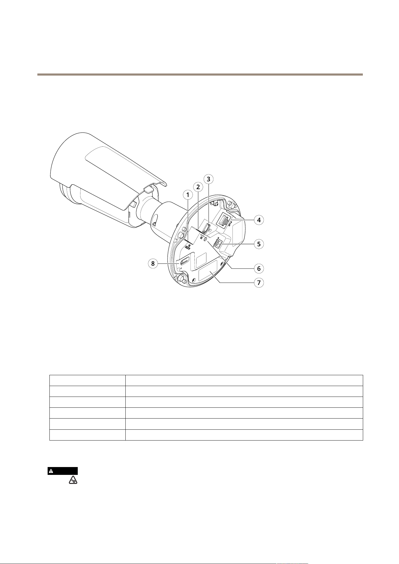
AXIS P1465-LE-3 License Plate Verifier Kit
Specifications
Specifications
Product overview
1
Audio connector
2
I/O connector
3
microSD card slot
4
Network connector
5
DC power input
6
Status LED indicator
7
Part number (P/N) & serial number (S/N)
8
Control button
LED indicators
Status LED
Indication
Unlit
Connection and normal operation.
Green Shows steady green for 10 seconds for normal operation after startup completed.
Amber
Steady during startup. Flashes during rmware upgrade or reset to factory default.
Amber/Red Flashes amber/red if network connection is unavailable or lost.
Red Firmware upgrade failure.
SD card slot
CAUTION
Risk of injury. Moving parts. Keep your body parts away from the product when in operation. Disconnect from power
supply before installing or performing maintenance on the product.
66

AXIS P1465-LE-3 License Plate Verifier Kit
Specifications
CAUTION
Risk of injury. Hot surface. Do not touch the product when in operation. Disconnect from power supply and allow the
surfaces to cool before performing maintenance on the product.
NONO
NO
TICETICE
TICE
• Risk of damage to SD card. Do not use sharp tools, metal objects, or excessive force when inserting or removing the
SD card. Use your ngers to insert and remove the card.
• Risk of data loss and corrupted recordings. Unmount the SD card from the product’s webpage before removal. Do not
remove the SD card while the product is running.
This product supports microSD/microSDHC/microSDXC cards.
For SD card recommendations, see axis.com.
microSD, microSDHC, and microSDXC Logos are trademarks of SD-3C LLC. microSD, microSDHC, microSDXC are
trademarks or registered trademarks of SD-3C, LLC in the United States, other countries or both.
Buttons
Control button
The control button is used for:
• Resetting the product to factory default settings. See Reset to factory default settings on page 70.
• Connecting to a one-click cloud connection (O3C) service over the internet. To connect, press and hold the button
for about 3 seconds until the status LED ashes green.
Connectors
Network connector
RJ45 Ethernet connector with Power over Ethernet (PoE).
Audio connector
• Audio in – 3.5 mm input for a mono microphone, or a line-in mono signal (left channel is used from a stereo signal).
• Audio in – 3.5 mm input for two mono microphones, or two line-in mono signals (using the supplied stereo-to-mono
adapter).
Audio input
1 Tip 2 Ring
3 Sleeve
Unbalanced microphone (with or without electret
power) or line
Electret power if selected
Ground
67
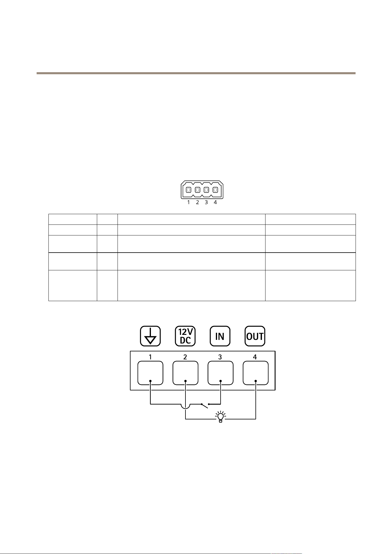
AXIS P1465-LE-3 License Plate Verifier Kit
Specifications
I/O connector
Use the I/O connector with external devices in combination with, for example, motion detection, event triggering, and alarm
notications. In addition to the 0 V DC reference point and power (12 V DC output), the I/O connector provides the interface to:
Digital input - For connecting devices that can toggle between an open and closed circuit, for example PIR sensors, door/window
contacts, and glass break detectors.
Digital output - For connecting external devices such as relays and LEDs. Connected devices can be activated by the VAPIX®
Application Programming Interface, through an event or from the product’s webpage.
4-pin terminal block
Function Pin Notes
Specications
DC ground
1
0 V DC
DC output
2
Can be used to power auxiliary equipment.
Note: This pin can only be used as power out.
12 V DC
Max load = 25 mA
Digital Input
3
Connect to pin 1 to activate, or leave oating (unconnected)
to deactivate.
0 to max 30 V DC
Digital Output
4
Internally connected to pin 1 (DC ground) when active,
and oating (unconnected) when inactive. If used with an
inductive load, e.g., a relay, connect a diode in parallel with
the load, to protect against voltage transients.
0 to max 30 V DC, open drain,
100 mA
Example
1
DC ground
2
DC output 12 V, max 25 mA
3
Digital input
4
Digital output
Connection example
68

AXIS P1465-LE-3 License Plate Verifier Kit
Specifications
Power connector
2-pin terminal block for DC power input. Use a Safety Extra Low Voltage (SELV) compliant limited power source (LPS) with either
a rated output power limited to ≤100 W or a rated output current limited to ≤5 A.
69

AXIS P1465-LE-3 License Plate Verifier Kit
Troubleshooting
Troubleshooting
Reset to factory default settings
WARNING
Possibly hazardous optical radiation is emitted from this product. It can be harmful to the eyes. Do not stare at
the operating lamp.
Important
Reset to factory default should be used with caution. A reset to factory default resets all settings, including the IP address, to
the factory default values.
Note
The camera has been precongured with AXIS License Plate Verier. If you reset to factory default, you will keep the license
key. You will not need to reinstall the application after a factory reset.
To reset the product to the factory default settings:
1. Disconnect power from the product.
2. Press and hold the control button while reconnecting power. See Product overview on page 66.
3. Keep the control button pressed for 15–30 seconds until the status LED indicator ashes amber.
4. Release the control button. The process is complete when the status LED indicator turns green. The product has been reset
to the factory default settings. If no DHCP server is available on the network, the default IP address is 192.168.0.90.
5. Use the installation and management software tools to assign an IP address, set the password, and access the device.
The installation and management software tools are available from the support pages on axis.com/support.
You can also reset parameters to factory default through the device’s webpage. Go to Maintenance > Factory default and click
Default.
Firmware options
Axis offers product rmware management according to either the active track or the long-term support (LTS) tracks. Being on the
active track means continuously getting access to all the latest product features, while the LTS tracks provide a xed platform with
periodic releases focused mainly on bug xes and security updates.
Using rmware from the active track is recommended if you want to access the newest features, or if you use Axis end-to-end system
offerings. The LTS tracks are recommended if you use third-party integrations, which are not continuously validated against the latest
active track. With LTS, the products can maintain cybersecurity without introducing any signicant functional changes or affecting
any existing integrations. For more detailed information about Axis product rmware strategy, go to axis.com/support/rmware.
Check the current rmware version
Firmware is the software that determines the functionality of network devices. When you troubleshoot a problem, we recommend
you to start by checking the current rmware version. The latest rmware version might contain a correction that xes your
particular problem.
To check the current rmware:
1. Go to the device interface > Status.
2. See the rmware version under Device info.
70

AXIS P1465-LE-3 License Plate Verifier Kit
Troubleshooting
Upgrade the rmware
Important
• Precongured and customized settings are saved when you upgrade the rmware (provided that the features are available in
the new rmware) although this is not guaranteed by Axis Communications AB.
• Make sure the device remains connected to the power source throughout the upgrade process.
Note
When you upgrade the device with the latest rmware in the active track, the product receives the latest functionality
available. Always read the upgrade instructions and release notes available with each new release before you upgrade the
rmware. To nd the latest rmware and the release notes, go to axis.com/support/rmware.
1. Download the rmware le to your computer, available free of charge at axis.com/support/rmware.
2. Log in to the device as an administrator.
3. Go to Maintenance > Firmware upgrade and click Upgrade.
When the upgrade has nished, the product restarts automatically.
You can use AXIS Device Manager to upgrade multiple devices at the same time. Find out more at
axis.com/products/axis-device-manager.
Technical issues, clues, and solutions
If you can’t nd what you’re looking for here, try the troubleshooting section at axis.com/support.
Problems upgrading the rmware
Firmware upgrade failure If the rmware upgrade fails, the device reloads the previous rmware. The most common reason
is that the wrong rmware le has been uploaded. Check that the name of the rmware le
corresponds to your device and try again.
Problems after rmware
upgrade
If you experience problems after a rmware upgrade, roll back to the previously installed version
from the Maintenance page.
Problems setting the IP address
The device is located on a
different subnet
If the IP address intended for the device and the IP address of the computer used to access the
device are located on different subnets, you cannot set the IP address. Contact your network
administrator to obtain an IP address.
The IP address is being used
by another device
Disconnect the Axis device from the network. Run the ping command (in a Command/DOS window,
type ping and the IP address of the device):
• If you receive: Reply from <IP address>: bytes=32; time=10...
this means that the IP address may already be in use by another device on the network.
Obtain a new IP address from the network administrator and reinstall the device.
• If you receive: Request timed out, this means that the IP address is available
for use with the Axis device. Check all cabling and reinstall the device.
Possible IP address conict
with another device on the
same subnet
The static IP address in the Axis device is used before the DHCP server sets a dynamic address.
This means that if the same default static IP address is also used by another device, there may
be problems accessing the device.
71

AXIS P1465-LE-3 License Plate Verifier Kit
Troubleshooting
The device can’t be accessed from a browser
Can’t log in
When HTTPS is enabled, ensure that the correct protocol (HTTP or HTTPS) is used when attempting
to log in. You may need to manually type http or https in the browser’s address eld.
If the password for the user root is lost, the device must be reset to the factory default settings.
See Reset to factory default settings on page 70.
The IP address has been
changed by DHCP
IP addresses obtained from a DHCP server are dynamic and may change. If the IP address has been
changed, use AXIS IP Utility or AXIS Device Manager to locate the device on the network. Identify
the device using its model or serial number, or by the DNS name (if the name has been congured).
If required, a static IP address can be assigned manually. For instructions, go to axis.com/support.
Certicate error when using
IEEE 802.1X
For authentication to work properly, the date and time settings in the Axis device must be
synchronized with an NTP server. Go to System > Date and time.
The device is accessible locally but not externally
To access the device externally, we recommend you to use one of the following applications for Windows
®
:
• AXIS Companion: free of charge, ideal for small systems with basic surveillance needs.
• AXIS Camera Station: 30-day trial version free of charge, ideal for small to mid-size systems.
For instructions and download, go to axis.com/vms.
Problems with streaming
Multicast H.264 only
accessible by local clients
Check if your router supports multicasting, or if you need to congure the router settings between
the client and the device. You might need to increase the TTL (Time To Live) value.
No multicast H.264
displayed in the client
Check with your network administrator that the multicast addresses used by the Axis device
are valid for your network.
Check with your network administrator to see if there is a rewall that prevents viewing.
Poor rendering of H.264
images
Ensure that your graphics card uses the latest driver. You can usually download the latest drivers
from the manufacturer’s website.
Color saturation is different
in H.264 and Motion JPEG
Modify the settings for your graphics adapter. Go to the adapter’s documentation for more
information.
Lower frame rate than
expected
• See Performance considerations on page 73.
• Reduce the number of applications running on the client computer.
• Limit the number of simultaneous viewers.
• Check with the network administrator that there is enough bandwidth available.
• Lower the image resolution.
• Log in to the device’s webpage and set a capture mode that prioritizes frame rate. If
you change the capture mode to prioritize frame rate it might lower the maximum
resolution, depending on the device used and capture modes available.
• The maximum frames per second is dependent on the utility frequency (60/50 Hz)
of the Axis device.
Can't select H.265 encoding
in live view
Web browsers don’t support H.265 decoding. Use a video management system or application
that supports H.265 decoding.
Unknown vehicles are marked as accepted
If the application lets in vehicles with license plates that are not in the allowlist, one probable reason is that the comparison
allows a deviation of one character.
For example, if AXI S1234 is in the allowlist the application accepts AXI SI234.
Similarly, if AXIS 1234 is in the allowlist the application accepts AXI 1234.
Go to Additional settings on page 20 to set the characters allowed.
72

AXIS P1465-LE-3 License Plate Verifier Kit
Troubleshooting
The connection between the application and controller or relay module doesn’t work
Make sure the controller, or relay module, allows data trafc through HTTP. To nd out how to change this setting, go to the user
manual for the corresponding device.
Performance considerations
When setting up your system, it is important to consider how various settings and situations affect the performance. Some factors
affect the amount of bandwidth (the bitrate) required, others can affect the frame rate, and some affect both. If the load on the
CPU reaches its maximum, this also affects the frame rate.
The following factors are the most important to consider:
• High image resolution or lower compression levels result in images containing more data which in turn affects the
bandwidth.
• Rotating the image in the GUI can increase the product's CPU load.
• Access by large numbers of Motion JPEG or unicast H.264 clients affects the bandwidth.
• Access by large numbers of Motion JPEG or unicast H.265 clients affects the bandwidth.
• Simultaneous viewing of different streams (resolution, compression) by different clients affects both frame rate and
bandwidth.
Use identical streams wherever possible to maintain a high frame rate. Stream proles can be used to ensure that
streams are identical.
• Accessing Motion JPEG and H.264 video streams simultaneously affects both frame rate and bandwidth.
• Accessing Motion JPEG and H.265 video streams simultaneously affects both frame rate and bandwidth.
• Heavy usage of event settings affects the product’s CPU load which in turn affects the frame rate.
• Using HTTPS may reduce frame rate, in particular if streaming Motion JPEG.
• Heavy network utilization due to poor infrastructure affects the bandwidth.
• Viewing on poorly performing client computers lowers perceived performance and affects frame rate.
• Running multiple AXIS Camera Application Platform (ACAP) applications simultaneously may affect the frame rate and
the general performance.
Contact support
Contact support at axis.com/support.
73

User manual Ver. M1.7
AXIS P1465-LE-3 License Plate Verier Kit
Date: April 2023
© Axis Communications AB, 2023
Part no. T10191704