LED Poster Display
Installation Guide

LED Poster Display Installation Guide
i
Legal Information
© 2022 Hangzhou Hikvision Digital Technology Co., Ltd. All rights reserved.
About this Manual
The Manual includes instructions for using and managing the Product. Pictures, charts, images and
all other information hereinafter are for description and explanation only. The information
contained in the Manual is subject to change, without notice, due to firmware updates or other
reasons. Please find the latest version of this Manual at the Hikvision website
(https://www.hikvision.com/).
Please use this Manual with the guidance and assistance of professionals trained in supporting the
Product.
Trademarks
and other Hikvision's trademarks and logos are the properties of
Hikvision in various jurisdictions.
Other trademarks and logos mentioned are the properties of their respective owners.
: The terms HDMI and HDMI High-Definition Multimedia Interface, and the HDMI
Logo are trademarks or registered trademarks of HDMI Licensing Administrator, Inc. in the United
States and other countries.
Disclaimer
TO THE MAXIMUM EXTENT PERMITTED BY APPLICABLE LAW, THIS MANUAL AND THE PRODUCT
DESCRIBED, WITH ITS HARDWARE, SOFTWARE AND FIRMWARE, ARE PROVIDED "AS IS" AND
"WITH ALL FAULTS AND ERRORS". HIKVISION MAKES NO WARRANTIES, EXPRESS OR IMPLIED,
INCLUDING WITHOUT LIMITATION, MERCHANTABILITY, SATISFACTORY QUALITY, OR FITNESS FOR
A PARTICULAR PURPOSE. THE USE OF THE PRODUCT BY YOU IS AT YOUR OWN RISK. IN NO EVENT
WILL HIKVISION BE LIABLE TO YOU FOR ANY SPECIAL, CONSEQUENTIAL, INCIDENTAL, OR INDIRECT
DAMAGES, INCLUDING, AMONG OTHERS, DAMAGES FOR LOSS OF BUSINESS PROFITS, BUSINESS
INTERRUPTION, OR LOSS OF DATA, CORRUPTION OF SYSTEMS, OR LOSS OF DOCUMENTATION,
WHETHER BASED ON BREACH OF CONTRACT, TORT (INCLUDING NEGLIGENCE), PRODUCT
LIABILITY, OR OTHERWISE, IN CONNECTION WITH THE USE OF THE PRODUCT, EVEN IF HIKVISION
HAS BEEN ADVISED OF THE POSSIBILITY OF SUCH DAMAGES OR LOSS.
YOU ACKNOWLEDGE THAT THE NATURE OF THE INTERNET PROVIDES FOR INHERENT SECURITY
RISKS, AND HIKVISION SHALL NOT TAKE ANY RESPONSIBILITIES FOR ABNORMAL OPERATION,
PRIVACY LEAKAGE OR OTHER DAMAGES RESULTING FROM CYBER-ATTACK, HACKER ATTACK,
VIRUS INFECTION, OR OTHER INTERNET SECURITY RISKS; HOWEVER, HIKVISION WILL PROVIDE
TIMELY TECHNICAL SUPPORT IF REQUIRED.
YOU AGREE TO USE THIS PRODUCT IN COMPLIANCE WITH ALL APPLICABLE LAWS, AND YOU ARE
SOLELY RESPONSIBLE FOR ENSURING THAT YOUR USE CONFORMS TO THE APPLICABLE LAW.
ESPECIALLY, YOU ARE RESPONSIBLE, FOR USING THIS PRODUCT IN A MANNER THAT DOES NOT
INFRINGE ON THE RIGHTS OF THIRD PARTIES, INCLUDING WITHOUT LIMITATION, RIGHTS OF

LED Poster Display Installation Guide
ii
PUBLICITY, INTELLECTUAL PROPERTY RIGHTS, OR DATA PROTECTION AND OTHER PRIVACY RIGHTS.
YOU SHALL NOT USE THIS PRODUCT FOR ANY PROHIBITED END-USES, INCLUDING THE
DEVELOPMENT OR PRODUCTION OF WEAPONS OF MASS DESTRUCTION, THE DEVELOPMENT OR
PRODUCTION OF CHEMICAL OR BIOLOGICAL WEAPONS, ANY ACTIVITIES IN THE CONTEXT RELATED
TO ANY NUCLEAR EXPLOSIVE OR UNSAFE NUCLEAR FUEL-CYCLE, OR IN SUPPORT OF HUMAN
RIGHTS ABUSES.
IN THE EVENT OF ANY CONFLICTS BETWEEN THIS MANUAL AND THE APPLICABLE LAW, THE
LATTER PREVAILS.

LED Poster Display Installation Guide
i
Symbol Conventions
The symbols that may be found in this document are defined as follows.
Symbol
Description
Danger
Indicates a hazardous situation which, if not avoided, will or could
result in death or serious injury.
Caution
Indicates a potentially hazardous situation which, if not avoided,
could result in equipment damage, data loss, performance
degradation, or unexpected results.
Note
Provides additional information to emphasize or supplement
important points of the main text.
Safety Instruction
For safety concerns, the device has been strictly tested before shipment. However, incorrect
installation or usage may lead to hazardous results such as electric shock and fire. To ensure the
service life and best performance of the device, please read the notice and plate signs carefully
and follow the safety instructions. Keep this guide properly for later use.
Caution
● To ensure safety, the installation parts and the wall should support four times the weight of the
device.
● Install the device no more than 5 mm away from the wall or other metal racks in case of lamp
board drop resulting in electric shock.
● Please set the brightness of the LED display within 500 nits to avoid power overload.
● The device may generate radio interference in indoor environment. Necessary precautions may
be required.
● To reduce the risk of fire or electric shock, please do not expose the device to rain or humid
environment.
● Electric discharge may last for a short period of time after the power is shut down. Please wait
two minutes after the power is shut down before operating the device.
● To avoid the risk of electric shock, please do not operate when the power is on.
● Please do not plug and unplug the power cable when the power is on.
● Ensure the correct wire sequence of the terminals connected to the AC power supply.
● Do not place anything containing liquid on the device to avoid the risk of fire or electric shock
caused by liquid-splashing.
● The device is only suitable for installation on the concrete or non-flammable surfaces, to
prevent molten material from dripping to the bottom during fire caused by internal failure.
● Keep 90 degrees when moving and using the device.

LED Poster Display Installation Guide
ii
● After installation, there should be no openings around the LED module. The bottom bracket
under the wire outlet position should completely cover the bottom hole only to let the wire out,
to prevent the molten material from dripping to the bottom during fire caused by internal
failure.
Warning
● In the use of the product, you must be in strict compliance with the electrical safety regulations
of the nation and region.
● Disconnect the power plug before maintenance.
● Make sure the power supply is well-grounded.
● The protective grounding of the device should be reliably connected to the building protective
grounding.
● To reduce the risk of electric shock, install protective shield on the exposed connector after
installing LED screen.
● Disconnect the power plug before installing the protective shield.
● A disconnecting device should be provided on the outside of the equipment. A single device is
recommended for AC 220 V / 230 V / 240 V, 6 A circuit breakers. When multiple devices are
superimposed, a suitable circuit breaker should be selected according to the total rated current,
but it must not exceed the building equipped circuit specifications.
● To prevent injury, the device must be securely fixed to the ground, wall, ceiling, or steel frame.
The all-in-one rack should be fixed to the ground with expansion screws.
● The supporting rack can only be used with the device. Using it with other devices may cause
instability and injury.
● The device can only be used with the supporting rack. Using it with other equipment (such as a
cart, shelf, or handling device) may cause instability and injury.
● Please strictly follow the installation method in this guide.
● The external wire connection between device and hazardous electronic terminals should be
operated by professionals.
● This is a class A product and may cause radio interference in which case the user may be
required to take adequate measures.

LED Poster Display Installation Guide
iii
Contents
Chapter 1 Introduction ............................................................................................................... 1
1.1 Product Introduction ............................................................................................................. 1
1.2 Key Features .......................................................................................................................... 1
Chapter 2 Installation ................................................................................................................. 2
2.1 About the Display .................................................................................................................. 2
2.1.1 Structure ..................................................................................................................... 2
2.1.2 Installation Methods .................................................................................................. 2
2.1.3 Precautions ................................................................................................................. 2
2.2 Single Display Installation ..................................................................................................... 3
2.2.1 Installation Holes ........................................................................................................ 3
2.2.2 Mobile Base Type ....................................................................................................... 3
2.2.3 Tilt Bracket Type ......................................................................................................... 8
2.2.4 Wall Mounting Type ................................................................................................. 11
2.3 Multi-Screen Splicing ........................................................................................................... 13
Chapter 3 Wiring ...................................................................................................................... 17
3.1 Interfaces ............................................................................................................................. 17
3.2 Instructions .......................................................................................................................... 17
Chapter 4 Installation Guide QR Code ......................................................................................... 1

LED Poster Display Installation Guide
1
Chapter 1 Introduction
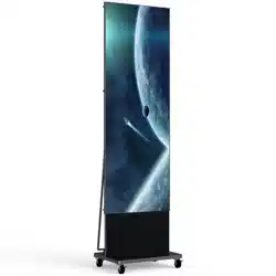
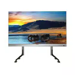
1.1 Product Introduction
LED poster display is an all-in-one vertical product. Made with two-color alloy, this thin display
features magnetic butterfly bezel design and supports seamless splicing of multiple screens. It can
either be served as a single display or be horizontally combined into a 1080p display. It presents
videos with high brightness and high contrast. From whichever perspective, you can always enjoy
its high-quality image. It supports various installation methods, such as conventional wall-
mounting, decorative wall-mounting, hanging, tilt bracket mounting, and mobile base mounting.
1.2 Key Features
● Even the thickest part of this thin display is only 28.1 mm or so. Its die-casting aluminum back
shell has perfect heat dissipation performance. It supports seamless splicing of multiple
screens.
● With strong magnetic absorption, the high-precision fool-proofing design of lamp boards
prevents being installed from the wrong side. The interior of the cabinets is infused with
simplicity and one-piece design, for better reliability, simple installation, and easy
maintenance. The cabinets support front maintenance, making it possible to dissemble lamp
boards, power supply, and receiving cards from the front side.
● Adopts Pix Master underlying image processing technology to optimize low-resolution source
images in one click and improve their clarity, contrast, and saturation.
● No need for professional equipment or operation, you can fast eliminate bright and dark lines
between screens with our advanced technology.
● Equipped with sending cards, this display supports HDMI input and network port output. You
can release materials and programs on the remote mobile or PC client.

LED Poster Display Installation Guide
2
Chapter 2 Installation
2.1 About the Display
2.1.1 Structure
The display should be used with a bracket, a mobile base, or a wall-mounting plate. You can
choose the appropriate installation method to assemble the display and the bracket according to
the actual situation.
Figure 2-1 Structure of LED Poster Display (Tilt Bracket Mounting)
2.1.2 Installation Methods
The display supports three types of installation: mobile base mounting, tilt bracket mounting, and
wall mounting.
2.1.3 Precautions
● Installation personnel must wear protective gear.
● Take safety measures when working at heights.
● Check that all structural parts and fasteners are fully mounted without missing.
● After all the accessories are mounted, clean all the debris in the bracket to avoid metal debris
being remained.
LED Poster Display Installation Guide
3
2.2 Single Display Installation
2.2.1 Installation Holes
The back decoration board of each cabinet is pre-designed with mounting holes for different
installation methods.
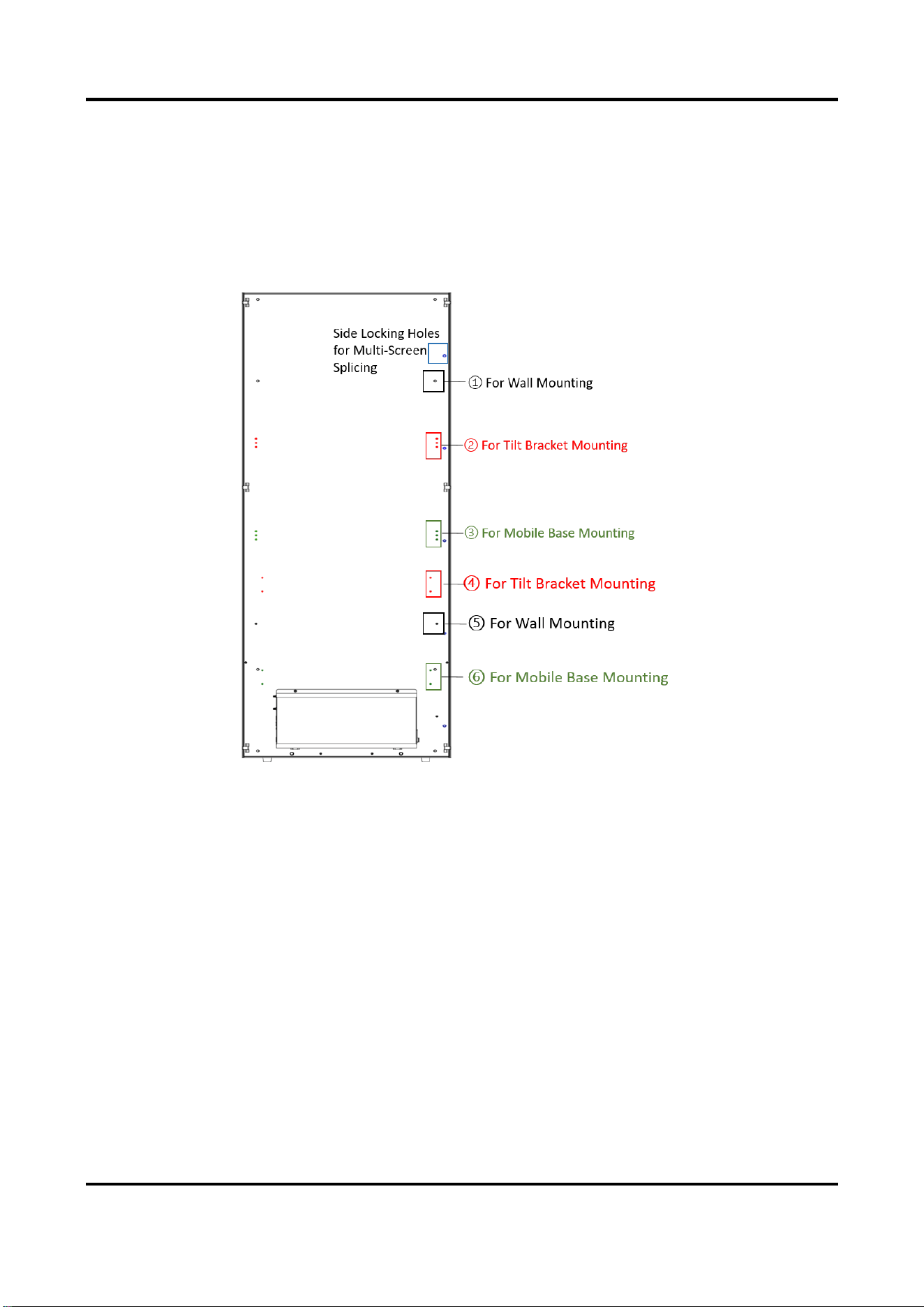
Figure 2-2 Installation Holes
There are six pairs of holes from top to bottom, including the first and fifth pairs for wall
mounting, the second and fourth pairs for tilt bracket mounting, and the third and sixth pairs for
mobile base mounting. Five side locking holes are reserved on one side of the board for multi-
screen splicing.
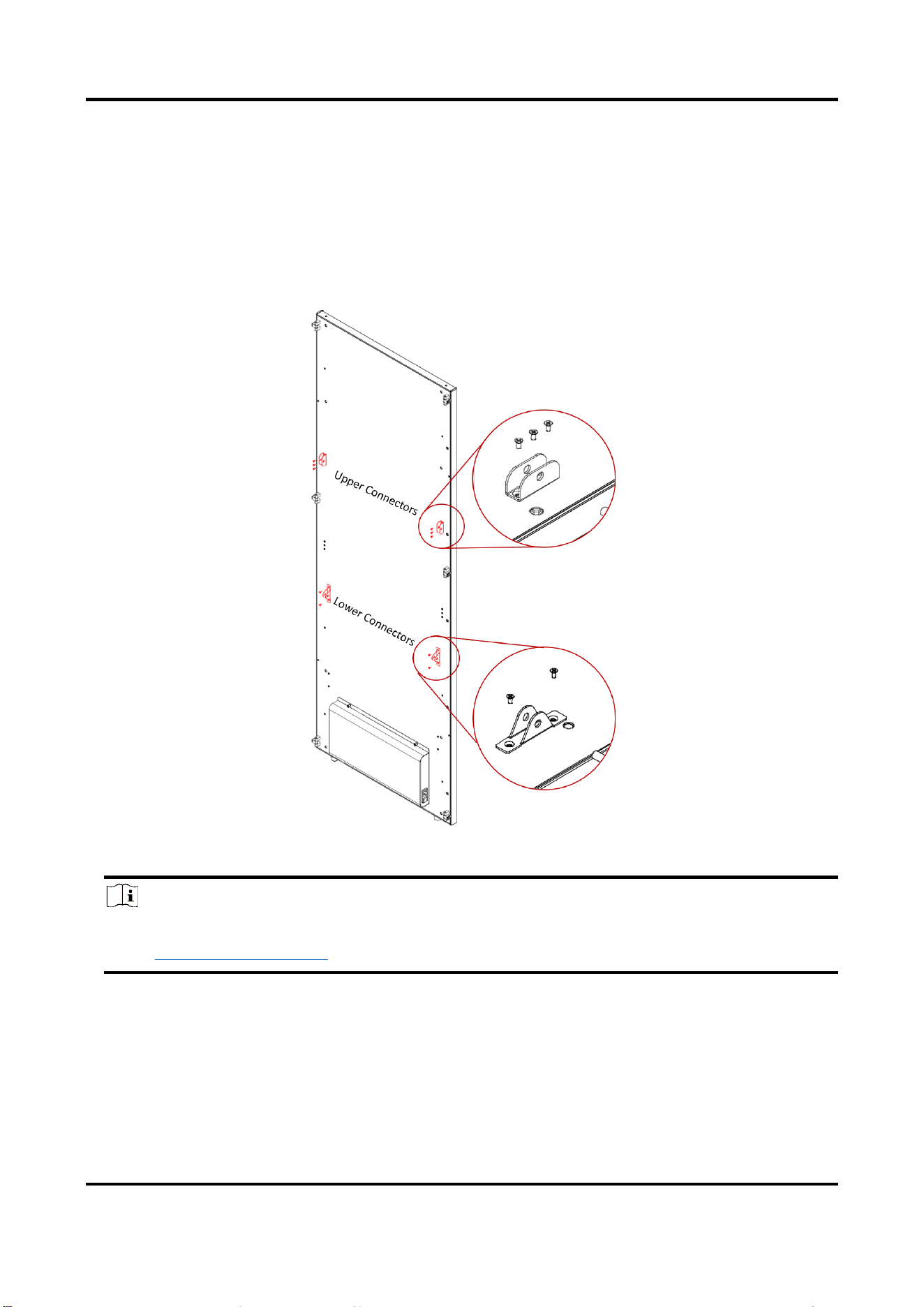
2.2.2 Mobile Base Type
Steps
1. Install connectors. Use three M3 screws and two M3 screws respectively to fix the upper and
lower connectors to the back decoration board of the cabinet.


LED Poster Display Installation Guide
5
2. Install the tilt bracket. Install the tilt bracket to the connectors and fasten the limit screws.
Figure 2-5 Install Tilt Bracket (Mobile Base)
Warning
When installing the tilt bracket with a mobile base, place the cabinet on a protected
horizontal surface and keep its back up, to protect the cabinet from falling over.
3. Install safety components. After determining where to place the display, install safety
components on the base and fix the components to the ground to prevent the display from
moving or falling over. Two components are set on the front side and two on the back side.

LED Poster Display Installation Guide
6
Figure 2-6 Install Safety Components (Mobile Base)
Note
In some cases, it is not possible to install safety components. You can choose whether to
install or not according to the actual situation.
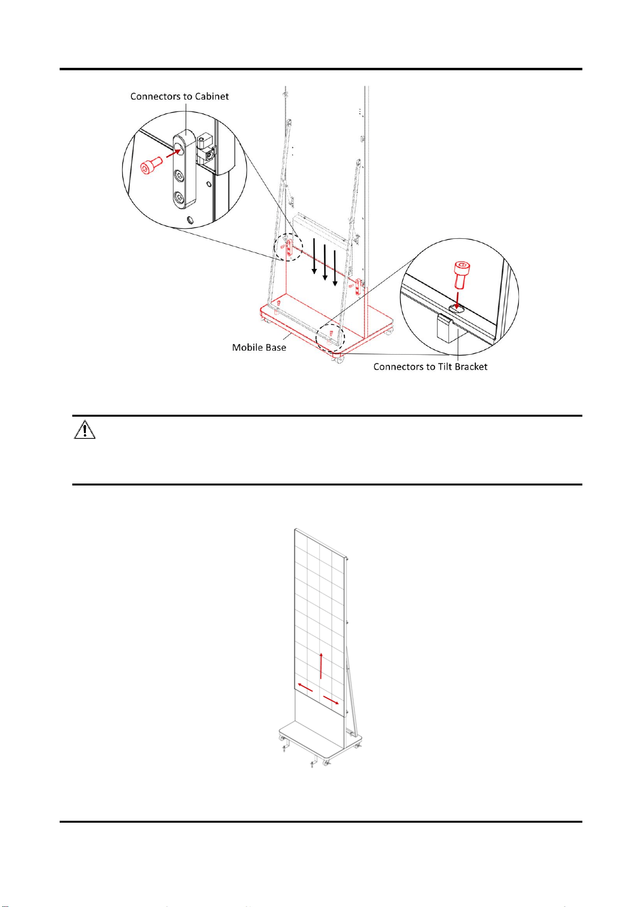
4. Install the mobile base. Place the cabinet with tilt bracket on the mobile base, and fix the
connectors to the cabinet and the tilt bracket with limit screws respectively.
LED Poster Display Installation Guide
7
Figure 2-7 Install Mobile Base
Warning
At least two people are needed to lift the cabinet and place it on the mobile base for
installation. Working alone is risky.
5. Install the modules. Attach the modules to the cabinet from bottom to top and from middle to
both sides.
LED Poster Display Installation Guide
8
Figure 2-8 Install Modules (Mobile Base)
2.2.3 Tilt Bracket Type
Steps
1. Install connectors. Use three M3 screws and two M3 screws respectively to fix the upper and
lower connectors to the back decoration board of the cabinet.
Figure 2-9 Install Connectors (Tilt Bracket)
Note
The second and fourth pairs of reserved holes are used for tilt bracket installation. For details,
see 2.2.1 Installation Holes.
2. Install the tilt bracket. Install the tilt bracket to the connectors and fasten the limit screws.

LED Poster Display Installation Guide
9
Figure 2-10 Install Tilt Bracket
3. Install safety components. After determining where to place the display, install safety
components at the bottom of the cabinet and fix the components to the ground to prevent the
display from moving or falling over.

LED Poster Display Installation Guide
10
Figure 2-11 Install Safety Components (Tilt Bracket)
Note
In some cases, it is not possible to install safety components. You can choose whether to
install or not according to the actual situation.
4. Install the modules. Attach the modules to the cabinet from bottom to top and from middle to
both sides.
Figure 2-12 Install Modules (Tilt Bracket)

LED Poster Display Installation Guide
11
2.2.4 Wall Mounting Type
Caution
● It must be a vertical load-bearing wall with clean surface for the display to be mounted on.
● The wall should be thicker than the length of installation screws. The reserved installation
area on the wall should be larger than the size of the display.
Steps
1. Install the wall-mounting plate. As shown in the following figure, drill holes at the given distance
and fix the wall-mounting plate to the wall by screws.
Figure 2-13 Installation Dimension
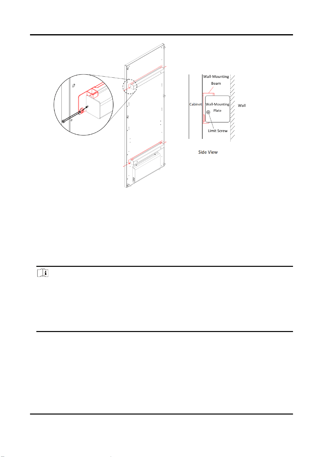
2. Install wall-mounting beams. As shown in the following figure, use M3 screws to fix wall-
mounting beams on the back decoration board of the cabinet.

LED Poster Display Installation Guide
12
Figure 2-14 Install Wall-Mounting Beams
Note
The first and fifth pairs of reserved holes are used for wall mounting. For details, see 2.2.1
Installation Holes.
3. Fix the cabinet. Hang wall-mounting beams of the cabinet to the wall-mounting plate, and drill
limit screws into both ends of the wall-mounting beams.
LED Poster Display Installation Guide
13
Figure 2-15 Fix Cabinet
4. Install the modules. Attach the modules to the cabinet from bottom to top and from middle to
both sides.
2.3 Multi-Screen Splicing
The display supports horizontal splicing of multiple screens, to meet the demand of different
screen sizes.
Note
● Displays of mobile base type and tilt bracket type can be spliced directly. For displays of wall
mounting type, direct splicing is not recommended. You need to customize wall-mounting
bracket according to your actual demand.
● After displays of mobile base type and tilt bracket type are spliced, do not move the displays.
Otherwise, the lamp beads may be broken. If you have to move the display, please remove
the lamp boards first.
Before You Start
The single display has been assembled with the bracket or mobile base.
Steps
1. Fold bezels. Fold the bezels of the cabinets that need to be spliced.

LED Poster Display Installation Guide
14
Figure 2-16 Fold Bezels
2. Splice cabinets. Align the cabinets side to side to splice.
Figure 2-17 Left-to-Right Splicing (Front View)
LED Poster Display Installation Guide
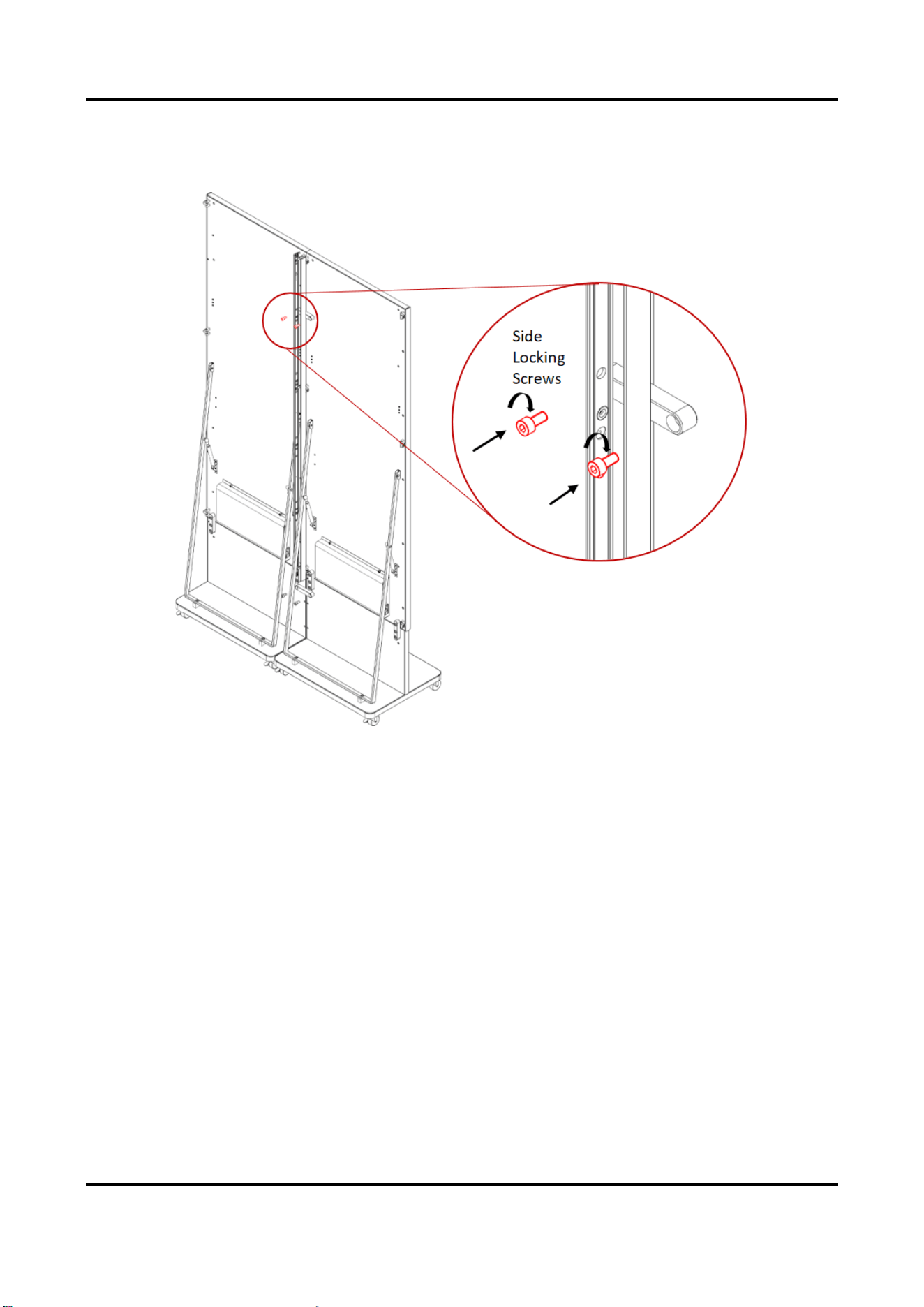
15
3. Lock side locks. Insert a 5 mm L-shaped hex wrench into the side locking holes and turn
clockwise from the back side of the cabinet or counterclockwise from the front side to lock the
side locks.
Figure 2-18 Lock Side Locks (Rear View)
4. Complete the splicing. Repeat the above steps to complete the splicing of other cabinets.

LED Poster Display Installation Guide
16
Figure 2-19 Splicing Completed
5. Install the modules. Attach the modules to the cabinets from bottom to top and from middle to
both sides.
Figure 2-20 Install Modules (Multi-Screen Splicing)
LED Poster Display Installation Guide
17
Chapter 3 Wiring
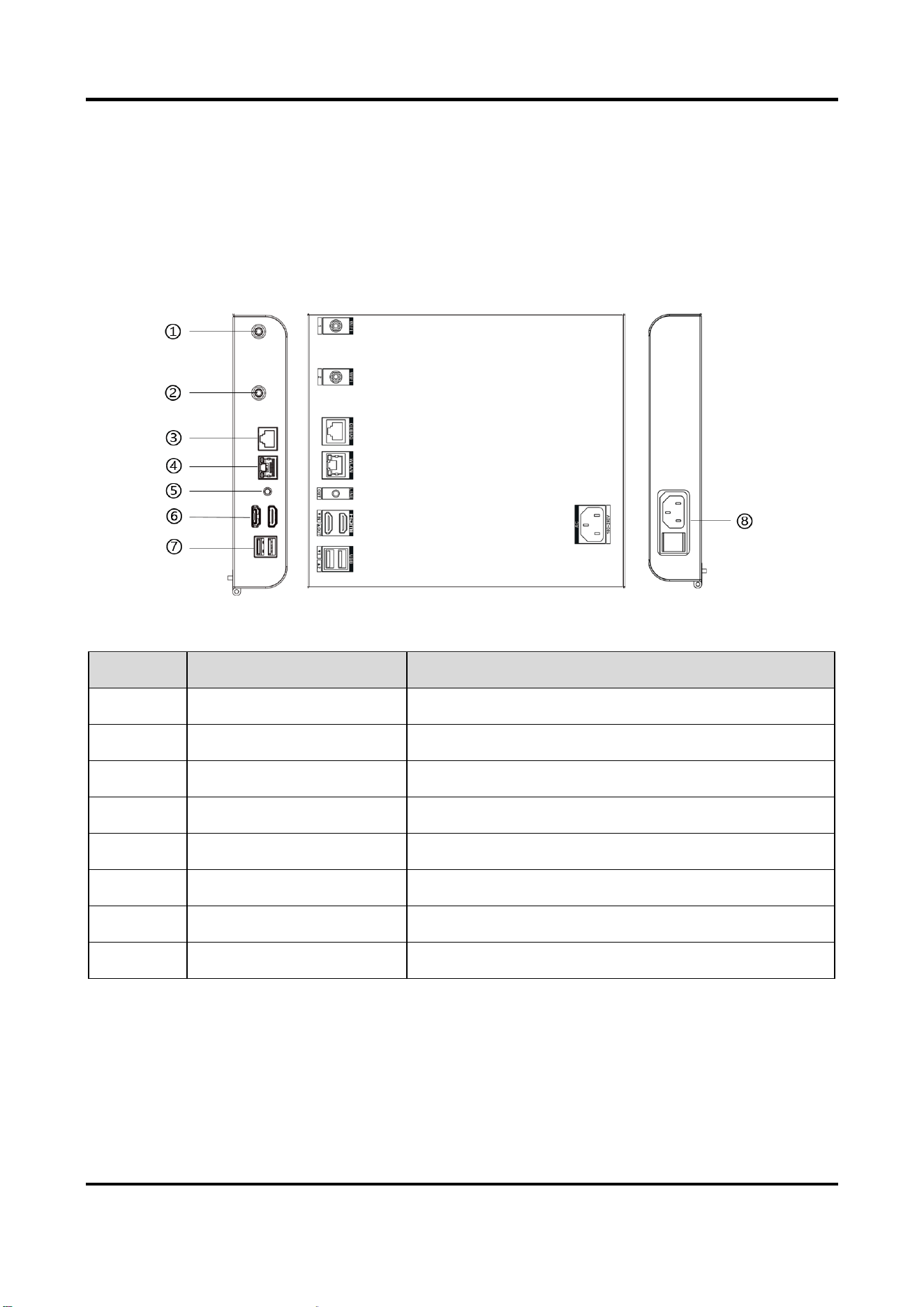
3.1 Interfaces
All the interfaces of the display can be found in the interface box on the back of the display.
Figure 3-1 Interface Box
Table 3-1 Interface Description
3.2 Instructions
After the installation is completed, connect the power cord and signal cables to the corresponding
No.
Name
Description
①
WIFI 1
Wi-Fi signal interface 1
②
WIFI 2
Wi-Fi signal interface 2
③
DEBUG
Serial port for debugging
④
WLAN
Network port for main control
⑤
LINE OUT
Audio signal output port
⑥
HDMI
HDMI signal input port
⑦
USB 1/2
USB 1/2
⑧
AC 100-240V
Power input

LED Poster Display Installation Guide
18
interfaces on the interface box.
LED Poster Display Installation Guide
1
Chapter 4 Installation Guide QR Code
Scan the QR code to read the installation guide online.
Figure 4-1 Installation Guide QR Code

UD29826B