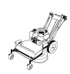
Wide-Cut
TM
33"
Combination Mower
Models 753B
E753B
Operator’s Manual
Warning: This unit is equipped with an internal combustion engine and should not be used on or near any unimproved forest-covered, brush-cov-
ered or grass-covered land unless the engine’s exhaust system is equipped with a spark arrester meeting applicable local or state laws (if any). If a
spark arrester is used, it should be maintained in effective working order by the operator. In the State of California the above is required by law
(Section 4442 of the California Public Resources Code). Other states may have similar laws. Federal laws apply on federal lands. A spark arrester
for the muffler is available by contacting the service department at Troy-Bilt LLC, P.O. Box 361131 Cleveland, Ohio 44136-0019.
IMPORTANT:READ SAFETY RULES AND INSTRUCTIONS CAREFULLY
TROY-BILT LLC, P.O. BOX 361131, CLEVELAND, OH 44136-0019
PRINTED IN USA FORM NO. 770-10602A
(01/2002)

For more details about your unit, visit our website at www.troybilt.com
TABLE OF CONTENTS
Content Page
Safety . . . . . . . . . . . . . . . . . . . . . . . . . . . . . . . . . . . . . . . . . . . . . . . . . . . . . . . . . . . . . . . . . . . 1
Assembly. . . . . . . . . . . . . . . . . . . . . . . . . . . . . . . . . . . . . . . . . . . . . . . . . . . . . . . . . . . . . . . . . 4
Features and Controls. . . . . . . . . . . . . . . . . . . . . . . . . . . . . . . . . . . . . . . . . . . . . . . . . . . . . . . 9
Operation . . . . . . . . . . . . . . . . . . . . . . . . . . . . . . . . . . . . . . . . . . . . . . . . . . . . . . . . . . . . . . . . 12
Maintenance . . . . . . . . . . . . . . . . . . . . . . . . . . . . . . . . . . . . . . . . . . . . . . . . . . . . . . . . . . . . . . 17
Lubrications. . . . . . . . . . . . . . . . . . . . . . . . . . . . . . . . . . . . . . . . . . . . . . . . . . . . . . . . . . . . . . . 25
Off-Season Storage . . . . . . . . . . . . . . . . . . . . . . . . . . . . . . . . . . . . . . . . . . . . . . . . . . . . . . . . 25
Troubleshooting . . . . . . . . . . . . . . . . . . . . . . . . . . . . . . . . . . . . . . . . . . . . . . . . . . . . . . . . . . . 28
Parts List . . . . . . . . . . . . . . . . . . . . . . . . . . . . . . . . . . . . . . . . . . . . . . . . . . . . . . . . . . . . . . . . . 29
Warrany Information . . . . . . . . . . . . . . . . . . . . . . . . . . . . . . . . . . . . . . . . . . . . . . . . . . . . . . . . Back Cover
FINDING MODEL NUMBER
This Operator’s Manual is an important part of your new Wide-Cut
TM
mower. It will help you assemble, prepare and
maintain the unit for best performance. Please read and understand what it says.
Before you start assembling your new equipment, please locate the model plate on the equipment and copy the infor-
mation from it in the space provided below. This information is very important if you need help from our Customer
Support Department or an authorized dealer.
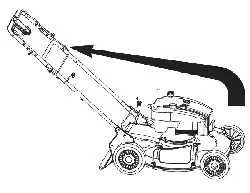
• You can locate the model number by looking at the rear surface of the tine shield. A sample model plate is ex-
plained below. For future reference, please copy the model number and the serial number of the equipment in
the space below
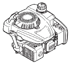
ENGINE INFORMATION
The engine manufacturer is responsible for all engine-related issues with regards to performance, power-rating,
specifications, warranty and service. Please refer to the engine manufacturer’s Owner’s/Operator’s Manual packed
separately with your unit for more information.
CALLING CUSTOMER SUPPORT
If you have difficulty assembling this product or have any questions regarding the controls, operation or maintenance
of this unit, please call the Customer Support Department.
Call 1- (330) 558-7220 or 1- (866) 840-6483 to reach a Customer Support representative. Please have
your unit’s model number and serial number ready when you call. See previous section to locate this in-
formation. You will be asked to enter the serial number in order to process your call .
Copy Model Number Here
Copy Serial Number Here
www.troybilt.com
TROY-BILT LLC
P. O. BOX
361131
CLEVELAND, OH 44136
866-840-6483
330-558-7220
Safety Alert Symbol
This is a safety alert symbol. It is used in this
Owner’s Manual to alert you to potential
hazards. Whenever you see this symbol, read and obey the
safety message that follows it. Failure to obey the safety
message could result in personal injury or property
damage.
The engine exhaust from this product contains
chemicals known to the State of California
to cause cancer, birth defects, or other reproduc-
tive harm.
WARNING:
1
IMPORTANT
Safe Operation Practices for Walk-Behind Mowers
This cutting machine is capable of amputating hands and feet and throwing objects. Failure to observe the
following safety instructions could result in serious injury or death.
1. Read, understand, and follow all in-
structions on the machine and in the
manuals. Be thoroughly familiar with
the controls and the proper use of
the mower before starting.
2. Do not put hands or feet near or
under rotating parts. Keep clear of
the mower blade and discharge
opening at all times.
3. Only allow responsible individuals,
who are familiar with the instruc-
tions, to operate the mower.
4. Clear the area of objects such as
rocks, toys, wire, bones, sticks, etc.,
which could be picked up and
thrown by the blade.
5. Be sure the area is clear of other
people before mowing. Stop mower
if anyone enters the area. Keep by-
standers at least 25 feet away from
the area of operation.
6. Do not operate the mower when
barefoot or wearing open sandals.
Always wear substantial foot wear.
7. Do not pull mower backwards
unless absolutely necessary. Look
down and behind before and while
moving backwards.
8. Do not operate the mower without
proper guards, plates, grass catcher
or other safety protective devices in
place.
9. Refer to provided instructions for
proper operation and installation of
accessories. Only use accessories
approved by Garden Way
Incorporated.
10. Stop the blade when crossing gravel
drives, walks, or roads.
11. Stop the engine and disconnect the
spark plug wire from the spark plug
whenever you leave the unit, before
cleaning the mower or unclogging
the chute.
12. Shut the engine off, wait until the
blade comes to a complete stop, and
disconnect the spark plug wire be-
fore installing or removing the
mulcher cover or the optional grass
catcher. Make certain that the grass
catcher is securely attached before
operating the mower. Empty the
grass catcher after each use–
decomposing debris could generate
enough heat to catch fire.
13. Mow in daylight or good artificial
light.
14. Do not operate the mower while
under the influence of alcohol or
drugs.
I. GENERAL OPERATION
Safety
1
Section

2
15. Never operate mower in wet grass.
Always be sure of your footing; keep
a firm hold on the handle and walk;
never run.
16. Disengage the Wheel Drive Lever on
self-propelled models before starting
the engine.
17. If the unit should start to vibrate ab-
normally, stop the engine and dis-
connect the spark plug wire. Then
check immediately for the cause.
Vibration is generally a warning of
trouble.
18. Always wear safety goggles or safety
glasses with side shields when oper-
ating mower.
19. Watch for traffic when operating
near, or when crossing roadways.
20. Never attempt to carry children or
other passengers on the mower.
They could fall off and be seriously
injured, or they could interfere with
the safe operation of the mower.
21. Check the operation of the Operator
Presence Control Bar before each
use. See the Maintenance Section of
this manual for instructions. If the
engine runs longer than three sec-
onds after the Operator Presence
Control Bar is released, the system
is not working properly. Immediately
contact your local service dealer or
the factory Technical Service
Department for instructions. Do not
use the mower until the mechanism
is repaired.
22. The mower is equipped with a safety
discharge chute, comes with special
mulcher covers, and offers an op-
tional grass catcher. The safety dis-
charge chute must be working prop-
erly at all times. Never attempt to
disconnect or otherwise cause this
discharge chute to cease working. If
used, mulcher cover or grass
catcher attachment must be installed
properly and function correctly. Do
not use your equipment otherwise.
23. Never run the engine in an enclosed
area. Engine exhaust contains carbon
monoxide, a deadly gas that is odor-
less, colorless, and tasteless. Always
run the engine outdoors and make
sure there is adequate ventilation.
II. SLOPE OPERATION
Slopes are a major factor related to
slip and fall accidents which can result
in severe injury. All slopes require
extra caution. If you feel uneasy on a
slope, do not mow it.
DO:
Mow across the face of slopes; never
up and down. Exercise extreme cau-
tion when changing direction on
slopes. Avoid slopes greater than
15
o
.
Remove objects such as rocks, tree
limbs, etc.
Watch for holes, ruts, or bumps. Tall
grass can hide obstacles.
DO NOT:
Do not mow near drop-offs, ditches,
or embankments. The operator could
loose footing or balance.
Do not mow excessively steep slopes.
Do not mow on wet grass. Reduced
footing could cause slipping.
III. CHILDREN
Tragic accidents can occur if the opera-
tor is not alert to the presence of chil-
dren. Children are often attracted to the
mower and to the mowing activity.
Never assume that children will remain
where you last saw them.
1. Keep children out of the mowing
area and under the watchful care of
a responsible adult.
2. Be alert and turn mower off if chil-
dren enter the area.
3. Before and while moving backwards,
look behind and down for small
children.
4. Never allow children to operate the
mower.
5. Use extra care when approaching
blind corners, shrubs, trees, or other
objects that may obscure vision.
IV. SERVICE
1. Use extra care in handling gasoline
and other fuels. They are flammable
and their vapors are explosive.
a) Use only an approved container.
b) Never remove gas cap or add
fuel when the engine is running.
Allow engine to cool before refu-
eling. Do not smoke.
c) Never refuel the machine
indoors.
d) Never store the machine or fuel
container inside where there is
an open flame, such as a water
heater, etc.
e) Move mower away from any
gasoline fumes before starting
the engine.
2. Never run an engine inside a closed
area.
3. Never make adjustments or repairs
with the engine running. Disconnect
the spark plug wire and keep the
wire away from the plug to prevent
accidental starting.
4. Keep all nuts and bolts, especially
the blade attachment bolts, tight and
keep equipment in good condition.
5. Never tamper with safety devices.
Check their operation regularly.
6. Keep mower free of grass, leaves or
other debris build-up. Clean up oil or
fuel spillage. Allow mower to cool
before storing.
7. After striking an object, stop the en-
gine and disconnect the spark plug
wire. Inspect the mower and repair,
if necessary, before restarting.
8. Never attempt to make mower cut-
ting height adjustments while the
engine is running.
9. Grass catcher components are sub-
ject to wear, damage and deteriora-
tion, which could expose moving
parts or allow objects to be thrown.
Frequently check components and
replace with factory recommended
parts, when necessary.
Section 1: Safety

3
10. Mower blades are sharp and can
cut. Wrap the blade or wear gloves,
and use extra caution when servic-
ing them.
11. Do not change the engine governor
setting or overspeed the engine.
12. Do not touch engine parts which
may be hot from operation. Allow
parts to cool completely before in-
specting, cleaning or repairing the
mower.
13. To access the underside of the
mower, tip the mower rearward. Do
not tip the mower forward or on ei-
ther of its sides, unless specifically
advised to do so in this manual.
14. Maintain or replace safety and in-
structional decals. Refer to the sep-
arate Parts Catalog for replacement
decal information.
15. For units equipped with electric
start:
a) Batteries produce explosive
gases. Keep sparks, flame,
cigarettes, etc., away. Ventilate
the area when charging the bat-
tery. Do not charge the battery in
an airtight space.
b) Do not use a battery charger
other than the one provided with
the mower.
c) The battery contains toxic mate-
rials. Do not damage the battery
case. If the case is broken or
damaged, avoid contact with the
battery contents.
d) Properly dispose of a damaged
or worn out battery. Check with
local authorities for proper dis-
posal methods.
e) Do not short circuit the battery.
Severe burns and fire can result.
Section 1: Safety
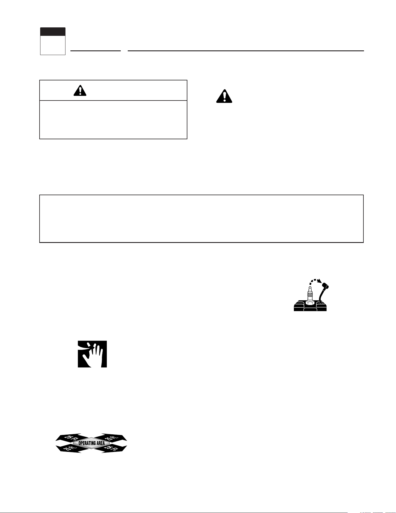
SAFETY DECALS
Make certain all safety decals on this equipment are kept clean and in good condition. The decals are shown (at reduced sizes)
below. If you need a replacement decal, please refer to the Parts Catalog that accompanied this Manual.
CAUTION
PINCH POINTS.
Do not operate with-
out all belt guards in
place.
Beneath belt/pulley
cover
On Control Panel (for electric start model)
On Control Panel (for recoil start model)
On left side of
mower deck
On top, rear of engine platform
A
CK
DANGER
KEEP HANDS and FEET AWAY
OBJECTS MAY BE THROWN
FROM MOWER.
• Before mowing, clear lawn
of all debris.
• Disengage wheel drive
before adjusting height.
WARNING
MAXIMUM SAFE OPERATING
ANGLE IS 15
O
.
• Exceeding maximum safe
operating angle may cause
tipping or loss of footing.
• Do not mow on wet slopes.
• Mow across slopes, not up
and down
WARNING
PLACE FOOT ON TIRE WHEN STARTING
1915475.A (11/97)
RELEASE OPERATOR
PRESENCE CONTROL
TO DISENGAGE
MOWER.
LIFT FOR
REVERSE
WARNING
TO AVOID SERIOUS INJURY READ ALL SAFETY
PRECAUTIONS CAREFULLY.
• Read owner/operator manual.
• Do not allow children or untrained adults to
operate machine.
• Use caution when approaching obstacles that
block your view.
• Keep all safety devices in place and in working
order.
• Do not mow when children or others are near.
• Disengage wheel drive before adjusting height.
3
2
1
N
R
4
4
INTRODUCTION
Please carefully follow these assembly
steps to properly prepare your machine
for use. We recommend that you read
this Section in its entirety before begin-
ning assembly.
NOTE: All references to left, right, front
and rear of the machine are determined
by standing behind the handlebars and
facing the direction of forward travel.
INSPECTION AFTER DELIVERY
Inspect the shipping crate and machine
immediately after delivery. Make sure
neither the carton nor the contents have
been damaged.
If you find or suspect any damage, con-
tact the carrier (trucking company)
immediately. Inform them of the specific
damage and that you wish to file a claim.
To protect your rights, be sure to put
this in writing to the carrier within 15
days. The carrier will let you know how
to proceed with your claim. Please let us
know if you need any assistance.
TOOLS/MATERIALS NEEDED:
• Wire Cutter
• 7/16” Wrench
• 3/8” Wrench
• Two 1/2” Wrenches
• Scissors or Pen Knife
• Needle-nose Pliers
• Motor Oil (see Step 5)
• Tire Gauge
ASSEMBLY STEPS
IMPORTANT: MOTOR OIL MUST BE
ADDED TO THE ENGINE BEFORE IT IS
STARTED. FOLLOW INSTRUCTIONS IN
THIS “ASSEMBLY” SECTION.
STEP 1: Unpacking Mower
NOTE: LEFT and RIGHT sides of the unit
are as viewed from the operator’s posi-
tion behind the handlebars.
1. Cut metal straps, if present, securing
unit to pallet. Leave unit on pallet during
assembly (to safely remove unit from
pallet, wait until you have completed as-
sembly steps 1-4).
2. Remove any protective packaging
from around the handlebars. Cut the
plastic tie straps holding the four long
control rods to the handlebars. Do not
remove the two long handlebar struts
that are attached to the top of the
handlebars.
STEP 2: Attach Handlebars
to Engine Deck
1. Remove the plastic ties holding the
wheel drive rod (F, Figure 2-7) to the left
handlebar and the blade drive rod (C,
Figure 2-7) to the right handlebar. Put
the rods aside.
NOTE: Four screws (D, Figure 2-2) are
used to connect the handlebars to the
engine deck. At the factory, these
screws are threaded into lock nuts
welded to the back sides of the deck .
2. Remove and save the four 5/16"-18
x 3/4" screws mentioned in the NOTE
above.
3. From the front of the unit, tilt the
right-side handlebar up over the air
cleaner cover and lift the other handlebar
upward. Rotate the handlebars over the
engine and position the handlebar ends
(E, Figure 2-2) against the sides of the
engine deck.
4. Swing the handlebar struts (A, Figure
2-2) forward and align the handlebar
ends (E, Figure 2-2) with the holes in the
engine deck. Loosely install two 5/16"-
18 x 3/4" hex flange screws removed
earlier (D) into the rear holes.
5. Align the loose ends of the handlebar
struts (A, Figure 2-2) over the front
holes in the handlebar ends. Attach the
struts and handlebars with two more
5/16"-18 x 3/4" hex flange screws.
Securely tighten all four screws.
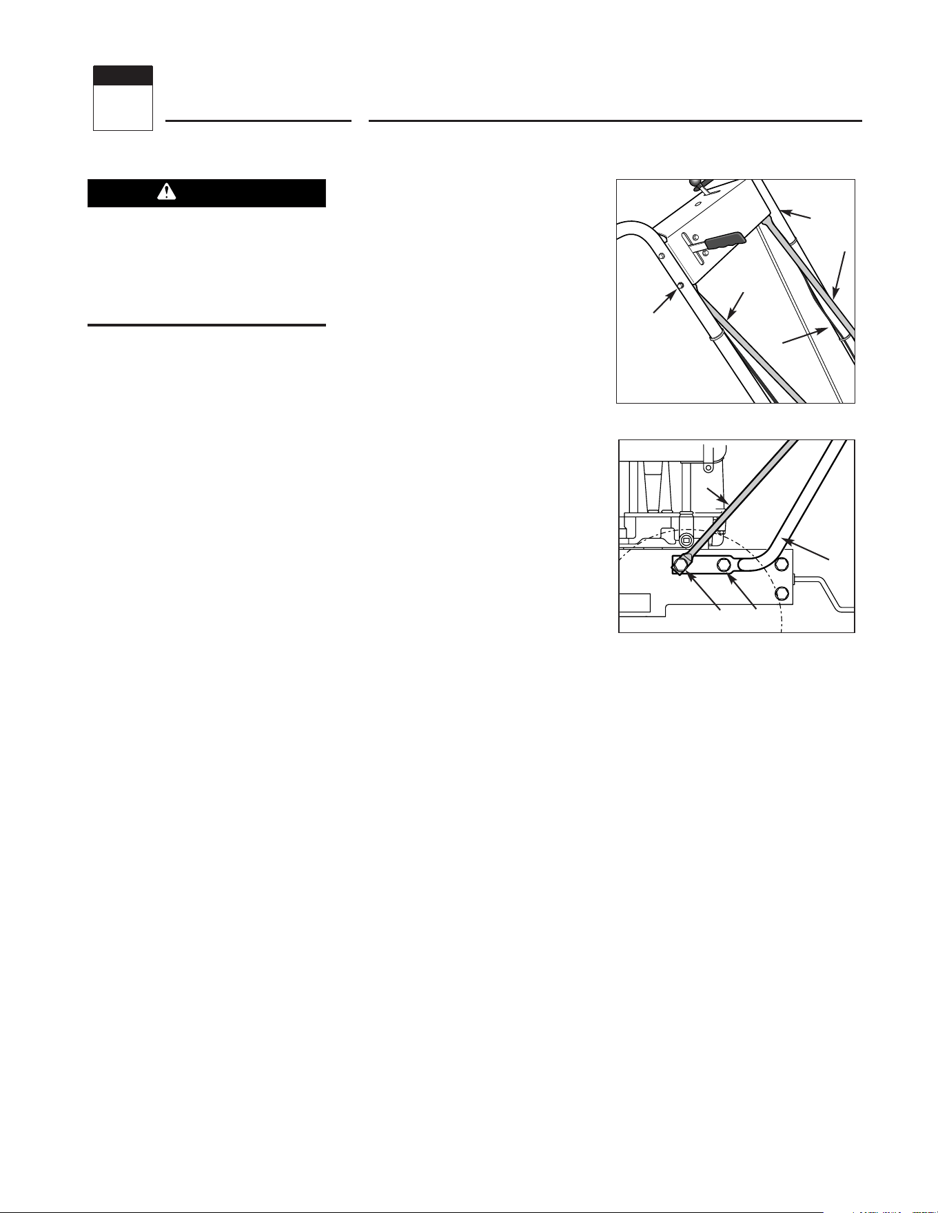
6. Securely tighten the screws (B, Figure
2-1) at the upper ends of the struts.
STEP 3: Electric Start Model
A. Secure Wire Harness
1. At the unattached end of the electrical
wire harness, there are four wires at-
tached to a large plastic connector and
two wires attached to a small plastic
connector.
To prevent personal injury or property
damage, do not attempt to start the
engine until all assembly steps are
complete and you have read and
understand the safety, controls and
operating instructions in this manual.
WARNING
Figure 2-1
B
B
C
A
A
A
D
E
D
Figure 2-2: Attach handlebars and struts
to engine deck.
Assembly
2
Section
Section 2: Assembly
2. Plug the large connector into the bot-
tom of the ignition keyswitch that is lo-
cated on the underside of the handlebar
console (not pictured).
3. Use two cable ties to secure the wire
harness to the right handlebar and away
from any moving parts. Place the ties an
equal distance apart.
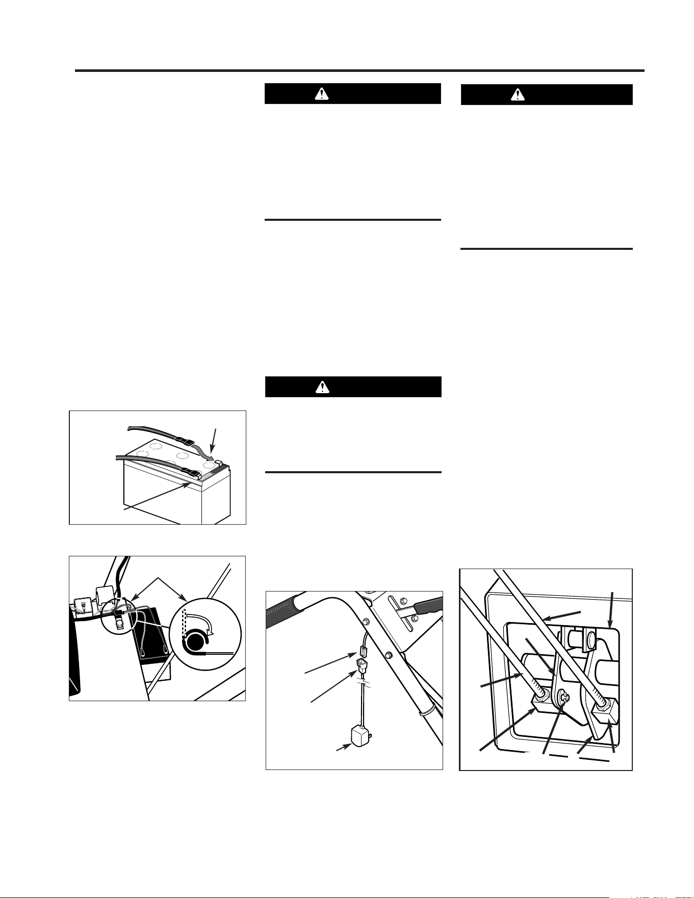
B. Attach Wire Leads to Battery
1. The battery is located at the rear,
right-side of the engine deck.
2. At the lower end of the electrical
wiring harness, locate a red wire lead
and a black wire lead.
• Plug terminal on red (positive) wire into
red terminal (U, Figure 2-3) on battery.
• Plug terminal on black (negative) wire
into black terminal (V).
3. If applicable, attach wire harness to
engine deck using J-clips (W, Figure
2-4) as shown. Bend J-clips over to
secure.
C. Charge the Battery
Charge a new battery for 24-48 hours to
ensure a full charge. If the mower must
be used immediately, the battery may
have enough of a charge to start the en-
gine. If not, the engine can be started
with the rope pull starter. NOTE: Charge
the battery after the initial use of the
mower to help ensure it is fully charged.
1. To charge the battery, locate the plas-
tic connector (T, Figure 2-5) that hangs
from the wire harness below the handle-
bar console.
2. Plug the connector on the battery
charger (Z, Figure 2-5) into the connec-
tor on the wire harness (T).
3. Plug the battery charger into a 120V
grounded wall outlet. NOTE: The battery
charger is designed for use indoors and
should not be exposed to rain or snow.
4. Charge battery for 24-48 hours.
5. After charging, unplug battery
charger from wall outlet, then unplug
charger from wire harness.
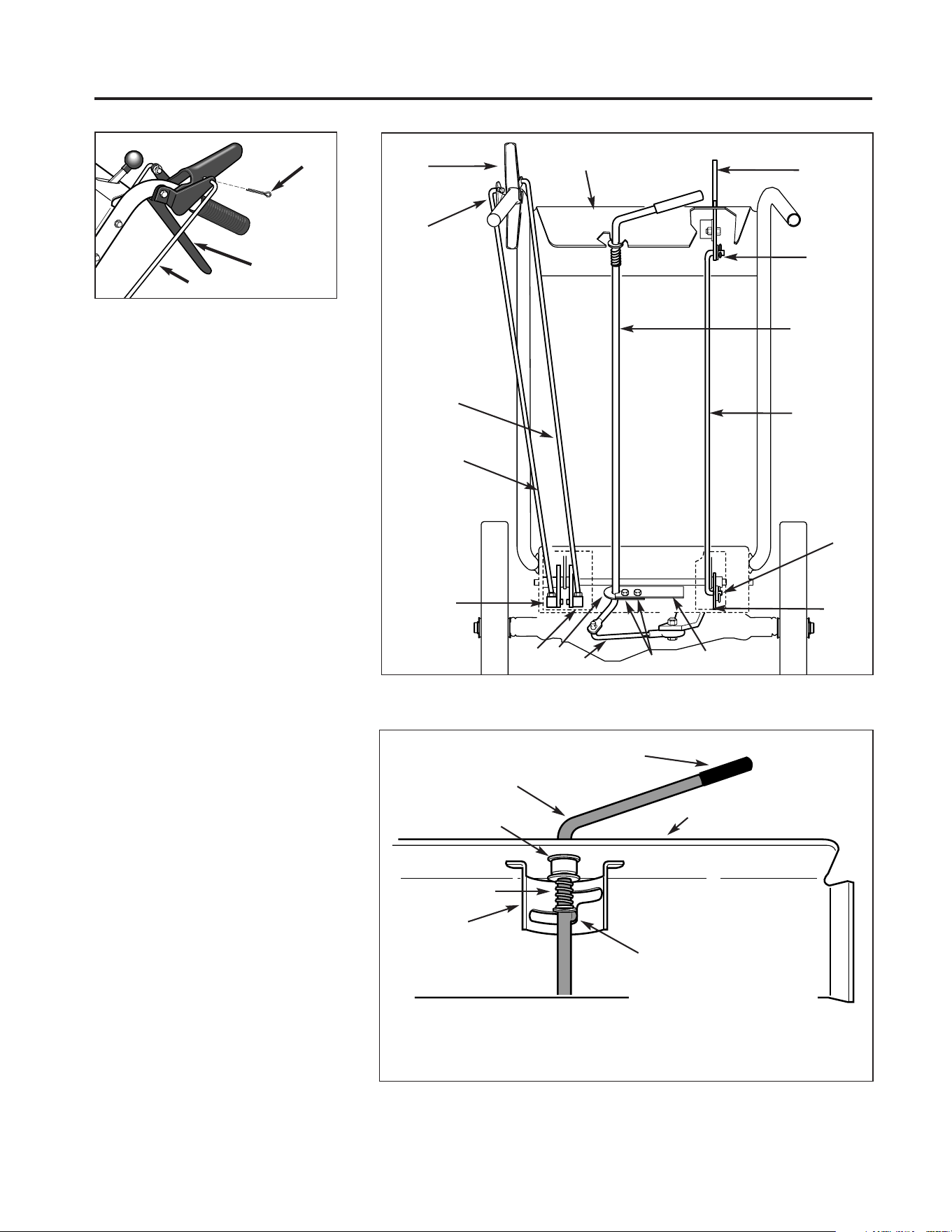
STEP 4: Attach Control Rods
A. Attach Wheel Drive Control Rod
1. Locate the wheel drive control rod (F,
Figures 2-6 & 2-7) that was removed
from the left handlebar in Step 2. This
rod has a swivel block (H, Figure 2-6) on
one end.
2. At left side of engine deck, insert
swivel block (H, Figures 2-6 & 2-7) on
wheel drive control rod into wheel drive
control arm (U, Figure 2-6).
Charge battery only with charger sup-
plied with machine. Do not short circuit
battery wires. Remove any jewelry be-
fore working on or near the battery or
electric start system.
Failure to follow these instructions
could result in personal injury or prop-
erty damage.
WARNING
Control rods are adjusted at the fac-
tory and should not require additional
adjustment during assembly. After as-
sembling unit, control rod
adjustment should be checked (and
re-adjusted, if necessary) according to
information in Maintenance Section.
Failure to follow this instruction could
result in severe personal injury or
property damage.
WARNING
If battery is removed, do not operate
engine without insulating positive (+)
battery cable terminal with electrical
tape or sparking from battery cells can
result.
CAUTION
(
Positive Lead)
Black (Ground Lead)
Figure 2-3: Connect wire terminals to
battery terminals.
Figure 2-4: Attach wire harness with J-
clips.
V
U
(-)
(+)
Red
(Positive
Lead)
Black (Ground Lead)
W
Figure 2-5
T
Z
To grounded
wall outlet
Figure 2-6: Left-hand control rods detail.
F
H
E
W
G
U
A, B
T
5
Section 2: Assembly
3. Add a 5/16" washer (A, Figure 2-6)
and attach with a hairpin clip (B).
4. At upper end of control rod, insert
angled end into Wheel Drive Control
lever (V, Figure 2-6A) and attach with a
cotter pin (BB). Bend ends of cotter pin
over rod to secure.
B. Attach Operator Presence Control
Rod
1. Locate control rod (E, Figures. 2-6
and 2-7) attached at upper end to
Operator Presence Control lever (W,
Figure 2-7).
2. At bottom of control rod, insert
swivel block (G, Figures 2-6 & 2-7) into
control arm (T, Figure 2-6).
3. Add one 5/16" washer and attach with
cotter pin. Bend ends of cotter pin to se-
cure.
C. Attach Blade Drive Control Rod
1. Locate the blade drive control rod (C,
Figure 2-7) that you removed in Step 2.
Insert one end of control rod into blade
drive bracket (D, Figure 2-7). Add one
5/16" washer and attach with hairpin clip
(CC).
2. Insert upper end of rod into bottom
end of Blade Drive Control lever (J,
Figure 2-7). Add one 5/16" washer and
attach with cotter pin (AA). Bend ends of
cotter pin to secure.
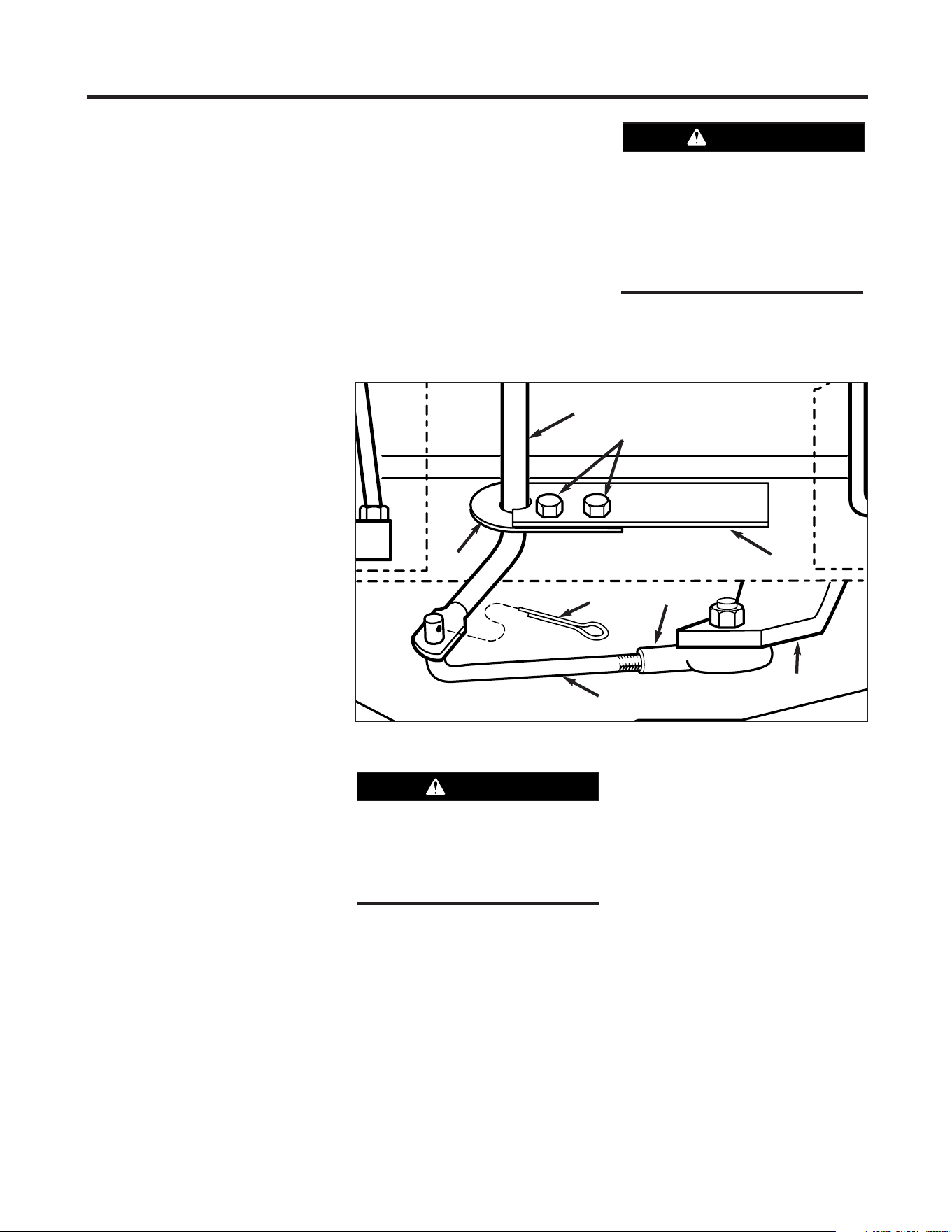
D. Attach and Adjust Gear Select Lever
NOTE: The retaining plate (N, Figure 2-7)
mentioned in the following steps is se-
cured to the rear of the mower with two
screws (O, Figure 2-7) and 1/4”-20 lock-
nuts. Remove the retaining plate and
save it, along with the two screws, be-
fore proceeding with assembly.
Figure 2-6A: Attach wheel drive control rod
to lever.
V
F
BB
Figure 2-7: Rear view of control rods.
G
N
P
O
H
F
E
I
C
J
AA
CC
D
L
M
V
W
Figure 2-8: Detail – Gear Select Lever in Neutral (N) position.
I
L
K
P
B
Z
Pin (K) must be in this detent
when transmission neutral is
adjusted.
J
6
7
Section 2: Assembly
1. Hold lower part of gear select lever
(I, Figure 2-9) against bracket (M).
Position retaining plate (N), removed
earlier, as shown in Figure 2-9 (plate
below bracket). Secure plate with two
1/4"-20 x 1/2" screws (O) and 1/4”-20
locknuts.
6. Slide grip (B, Figure 2-8) back onto
gear select lever (I).
7. Rotate gear select lever (I, Figures 2-
8 & 2-9) clockwise until spur (K - short
rod) on gear select rod stops in the neu-
tral position detent on the shift pattern
quadrant (Figure 2-8).
8. At bottom of control rod, thread shift
link (P, Figure 2-9) partially into ball-
joint (Y).
9. Move shift arm (X, Figure 2-9) from
side to side as necessary into each
transmission gear detent until transmis-
sion is in neutral.
NOTE: Moving shift arm (X) all the way
to the left, and then one notch back to
the right, should put transmission into
neutral. When transmission is in neutral,
unit will move freely when pushed while
holding the Operator Presence Control
lever (W, Figure 2-7) down. If transmis-
sion is NOT in neutral, there will be a
slight drag on the wheels when pushing
unit.
10. When shift arm (X) is in neutral po-
sition, rotate shift link (P) toward end of
gear select lever rod (I). Adjust length
of shift link (P) as necessary to fit into
hole in bottom of gear select lever (I).
NOTE: Pin (K) on Gear Select Lever (I)
must be held in the neutral position
detent on the shift quadrant (see Figure
2-8) while shift link (P, Figure 2-9) is
adjusted.
11. Insert hooked end of shift link (P,
Figure 2-9) into hole in bottom end of
gear select lever (I) and secure with cot-
ter pin (Q). Bend ends of cotter pin.
NOTE: It may be necessary to lift gear
select lever (I) to install shift link (P).
12. Remove unit from shipping crate.
To remove, hold down Operator
Presence Control lever (W, Figure 2-7)
which releases the wheel brake.
13. With unit on level ground, hold
down Operator Presence Control lever
(W, Figure 2-7) and push unit forward
and backward. The wheels should move
freely. If not, adjust length of shift link
(P, Figure 2-9) as necessary.
14. Put the Gear Select Lever in neutral
(N), release all of the control levers and
try to push the unit forward and back-
ward. The wheels should not turn. If
they do turn, an adjustment is neces-
sary. DO NOT OPERATE THE UNIT
UNTIL THE WHEEL BRAKE MECHANISM
HAS BEEN ADJUSTED AND IS WORK-
ING PROPERLY. See “Wheel Brake
Adjustment” in Section 5 “Maintenance.”
STEP 5: Add Motor Oil to Engine
1. Move mower to a level area. Press
and hold Operator Presence Control
lever (W, Figure 2-7) to move mower.
2. Add motor oil according to the speci-
fications and instructions provided in the
separate Engine Owner’s Manual that was
included in the unit’s literature package.
• Keep oil level at the FULL mark on the
dipstick to avoid engine damage.
• Change oil according to schedule and
instructions in Section 5 “Maintenance.”
STEP 6: Check Tire Pressure
1. Use a tire gauge to check the air
pressure in the rear tires. The air pres-
sure should be between 15-20 PSI (20
PSI maximum).
2. Keep both tires equally inflated to
help prevent machine from pulling to
one side.
STEP 7: After Assembling and
Before Using Unit
1. Read this entire Owner’s Manual for
proper safety, operation and mainte-
nance information.
2. Make sure spark plug wire is con-
nected to spark plug before starting unit.
Figure 2-9: Detail – Transmission Neutral Adjustment.
P
I
X
Y
Q
M
N
O
Do not use the mower if the wheels
continue to turn after releasing the
Operator Presence Control and the
Wheel Drive Control.
Severe personal injury or property
damage could result if this instruction
is not followed.
WARNING
Unit is shipped without oil in engine
crankcase. Do not start engine until oil
has been added. Severe engine dam-
age will result if this instruction is not
followed.
CAUTION
8
IMPORTANT: THE MOWER IS
EQUIPPED WITH A BLADE-BRAKE-
CLUTCH CONTROL SYSTEM WHICH IS
DESIGNED TO STOP THE MOWER
BLADES WITHIN THREE (3) SECONDS
AFTER RELEASE OF THE OPERATOR
PRESENCE CONTROL. THIS SYSTEM
WILL STOP THE BLADES BUT NOT THE
ENGINE. THEREFORE, YOU CAN DISEN-
GAGE THE BLADE DRIVE AT ANYTIME
WITHOUT HAVING TO STOP AND
RESTART THE ENGINE. THIS FEATURE
IS PARTICULARLY USEFUL WHEN YOU
NEED TO CROSS GRAVEL DRIVES OR
ROUGH TERRAIN AND YOU DO NOT
WANT THE SPINNING BLADES
TO STRIKE STONES OR HIDDEN
OBSTACLES.
MOWER FEATURES AND
CONTROLS
This section describes the various
features and controls on the unit. Refer
to the next section “Operation” for
detailed operating instructions. Also,
read the separate Engine Owner’s
Manual for a detailed explanation of the
proper use of the engine controls.
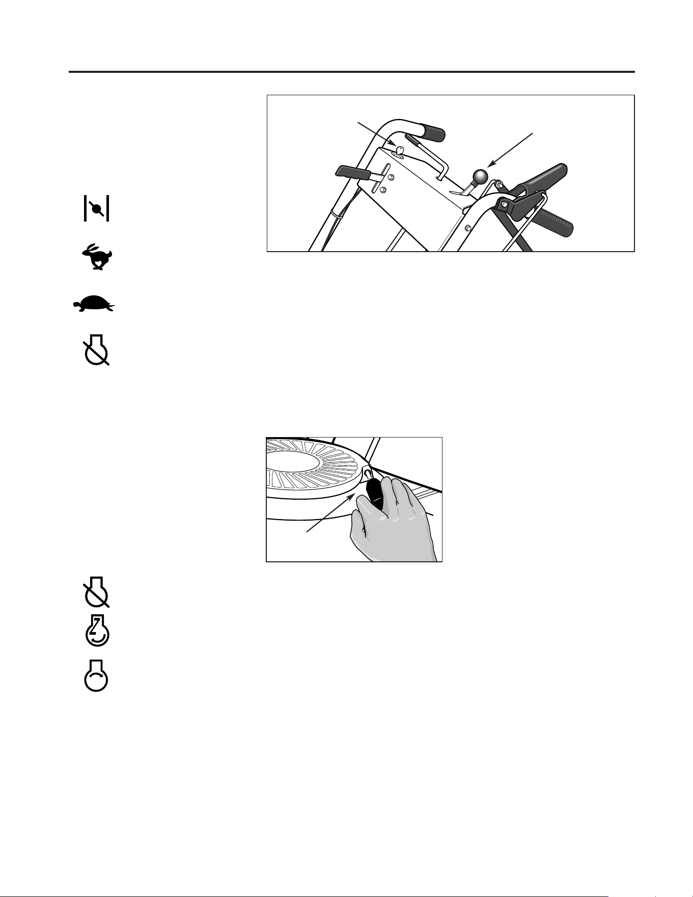
Operator Presence Control
The Operator Presence Control lever
(A, Figure 3-1) regulates the operation of
the rear wheel brake and the separate
Blade Drive Control. Always engage this
control before engaging the separate
blade drive or wheel drive controls.
Always disengage this control before
starting the engine.
To engage the Operator Presence
Control, press and hold the lever against
the handlebar grip. Doing so releases
the brake on the rear wheels, allowing
the wheels to turn. The engaged position
also permits the separate Blade Drive
Control to lock in its engaged position
(allows the mower blades to turn).
Releasing the lever (disengaged
position) applies the rear wheel brake
and quickly stops the wheels. Releasing
the lever will also disengage the Blade
Drive Control, which will apply a brake
that stops the blades within three (3)
seconds.
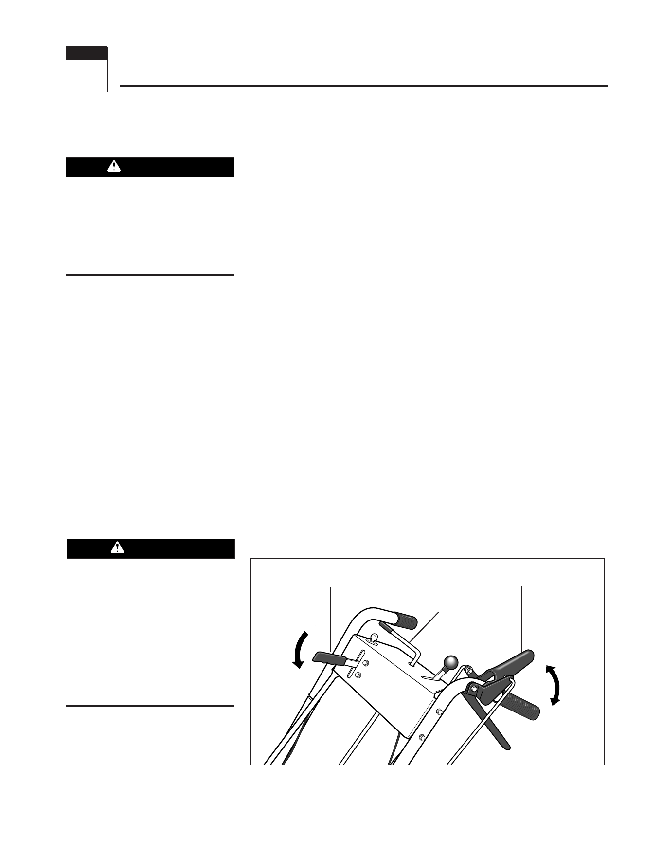
Blade Drive Control
Use this lever (B, Figure 3-1) to en-
gage drive to the mower blades.
To engage the blades, first engage the
Operator Presence Control (A, Figure 3-
1). Then, push the spring-loaded Blade
Drive Control lever (B) forward until it
stays in the engaged position.
To stop the blades, release the
Operator Presence Control (A). Doing so
will disengage the Blade Drive Control
(B) and automatically apply the brake
that stops the blades.
Always disengage the Blade Drive
Control before starting the engine. This
helps to ensure that the blades will not
start turning when the engine starts.
NOTE: Pushing the Blade Drive Control
forward will engage the blades even
though the Operator Presence Control is
not engaged. However, this procedure is
NOT RECOMMENDED as you must main-
tain constant pressure on the lever (re-
leasing lever disengages blades). Always
engage the Operator Presence Control
before engaging the Blade Drive Control.
Before operating mower, be sure to
read all safety, controls and operating
instructions in this Manual and on
decals located on machine.
Severe personal injury or property
damage could result if this instruction
is not followed.
WARNING
The blade-brake-clutch control system
should stop the mower blades within
three (3) seconds after release of the
Operator Presence Control.
If the blades do not stop within three
(3) seconds, put the Engine Throttle
Control in the STOP position.
Disconnect the spark plug wire and do
not operate the mower until the blade-
brake-clutch control system has been
repaired.
WARNING
B – BLADE
DRIVE CONTROL
A – OPERATOR
PRESENCE CONTROL
C – GEAR
SELECT LEVER
Disengage
Engage
Figure 3-1
Features and Controls
3
Section
Engage
9
Section 3: Features and Controls
Gear Select Lever
Use this lever (C, Figure 3-1) to select
any of four forward ground speeds (1 -
Slow, 2 and 3 - Medium, 4 - Fast), N
(Neutral) and R (Reverse). The gear shift
pattern is shown in Figure 3-2.
To avoid damaging the transmis-
sion, do not shift gears when the
mower is moving.
For forward travel, use one of the four
numbered settings. To select reverse,
shift to neutral and then pull up on the
lever. Turn the lever to the R (reverse)
position and release the lever.
Put the lever in N (neutral) to manu-
ally push the mower and when the
mower is not in use.
Wheel Drive Control
Use this lever (D, Figure 3-3) to en-
gage and disengage drive to the wheels.
To engage the wheels, first select a
forward or reverse gear with the Gear
Select Lever and squeeze the Operator
Presence Control (A, Figure 3-3). Then,
squeeze the Wheel Drive Control lever
(D) against the handlebar grip. The
ground speed can be varied by increas-
ing or decreasing pressure on the lever.
To avoid sudden acceleration, slowly
squeeze the lever when first engaging
the wheels.
Release the Wheel Drive Control to
disengage the wheels. The wheels will
gradually slow to a stop. NOTE: To stop
the wheels quickly, release the Operator
Presence Control along with the Wheel
Drive Control.
When starting the engine, the Wheel
Drive Control should be disengaged (re-
leased). This helps to ensure that the
wheels will not start turning when the
engine starts.
Cutting Height Control Lever
Use this lever (E, Figure 3-4) to adjust
the cutting height from 1 to 4 inches.
Note that actual cutting heights will vary
according to soil conditions.
Turn the lever clockwise to raise the
height or counterclockwise to lower the
height. A decal and pointer (not illus-
trated) on the right side of the mower
deck show the cutting height settings
ranging from A (highest) to G (lowest).
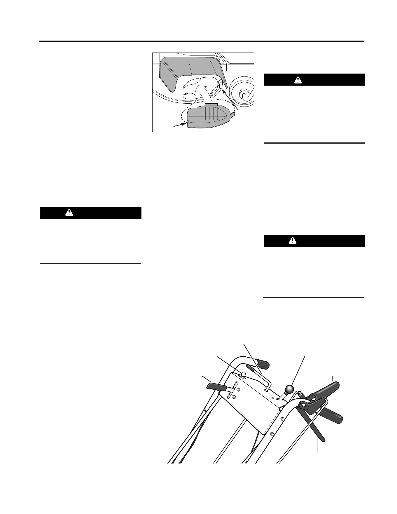
Mulcher Cover
The mulcher cover (F, Figure 3-5) is
pre-installed at the factory. It must be
kept in place when using the unit as a
mulching mower. The mulcher cover is
designed to keep the discharge chute
raised up while you mow. When the
cover is removed for side-discharge
mowing, the discharge chute lowers.
Refer to “4. Select Mulching or Side-
Discharge Mowing” in the Operation
Section for mulcher cover installation
instructions.
Figure 3-2:
Shift pattern
on console.
LIFT FOR
REVERSE
3
2
1
N
R
4
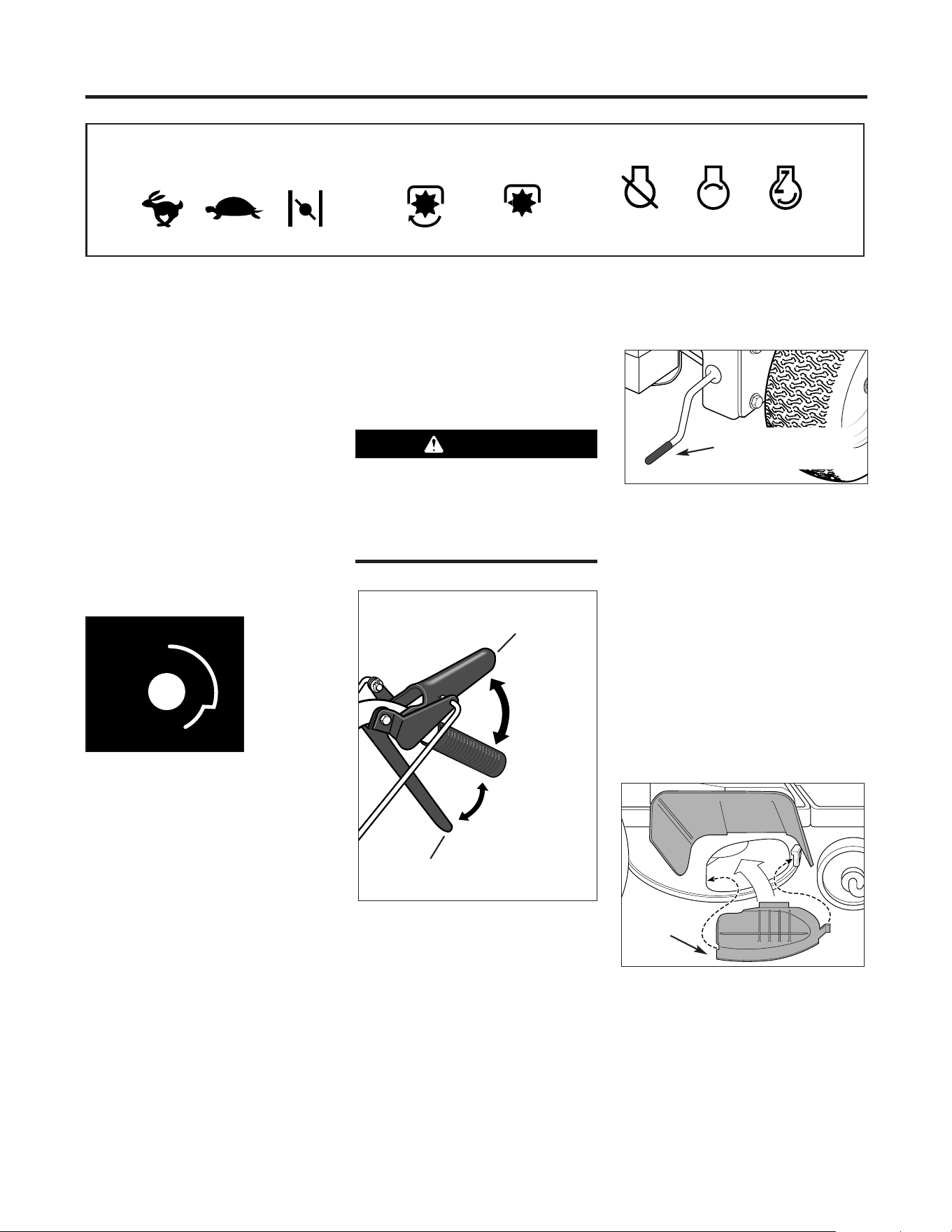
Operating Symbols Various symbols are used on the mower to indicate control settings (your model may not have all of the
symbols). These symbols are shown below with a description of their meaning.
FAST
SLOW
CHOKE
ENGINE
STOP
ENGINE
START
ENGINE
RUN
ENGAGE
DISENGAGE
Do not engage the Wheel Drive Control
without first engaging the Operator
Presence Control. Doing so could
result in wear or damage to the wheel
brake mechanism.
CAUTION
A – OPERATOR
PRESENCE CONTROL
D – WHEEL
DRIVE CONTROL
Disengage
Disengage
Engage
Engage
Figure 3-3
Figure 3-4
E – CUTTING HEIGHT
CONTROL LEVER
F
Figure 3-5
10
Engine Throttle Control
This lever (G, Figure 3-6) is used to
adjust engine speeds and to stop the en-
gine. Always run engine at fast speed
setting for best mower performance.
The throttle settings are shown below.
Ignition/Starter Switch -
(Electric Start Model)
This three-position switch (H, Figure
3-6) is used to start and stop the
engine on electric start models. The ig-
nition key settings are shown below. Do
not turn the key until you have read the
Operation Section in this Manual.
Always remove ignition key when
leaving mower unattended or when in-
specting, cleaning or servicing mower.
Engine Recoil Starter
The recoil starter (I, Figure 3-7) is
used to “pull-start” the engine. Detailed
instructions for using the recoil starter
are found in the Operation Section of this
Manual and in the Engine Owner's
Manual. Do not pull the recoil starter
until you have read the Operation
Section.
Section 3: Features and Controls
STOP - Stops engine.
RUN - After starting, key
returns to run position.
START - Starts engine.
Release key when engine
starts.
Figure 3-6
G – THROTTLE CONTROL
H – IGNITION/STARTER
SWITCH
CHOKE
- Use when
starting a cold engine.
FAST - Use during mower
operation.
SLOW - Use when idling
engine.
STOP - Stops engine.
I – RECOIL
STARTER
Figure 3-7

11
BEFORE OPERATING MOWER
1. Pre-Operation Checklist
With the spark plug wire disconnected
from the spark plug, perform the follow-
ing checks and services before each use:
1. Review Section 1: “Safety” and Section
3, “Features and Controls” in this man-
ual. Read the separate Engine Owner’s
Manual provided with the unit.
2. Check unit for loose or missing hard-
ware. Tighten or replace as needed.
3. With the unit on level ground, check
the engine oil level according to the
instructions in the Engine Owner’s
Manual. The oil level should be at the
FULL mark on the dipstick or up to the
top of the oil fill hole on engines with-
out a dipstick.
4. Check all levers for freedom of move-
ment. Readjust or repair as needed
before starting engine.
5. Check that all guards and shields are
in place and properly secured.
6. Inspect the area to mowed and re-
move any debris which could be
picked up and thrown by the mower
blades.
7. Check that the mulcher cover is prop-
erly installed in the discharge opening
(see instructions in this Section).
Remove the mulcher cover to use the
side-discharge mowing feature.
8. On electric start models, check that
all wiring connections are clean and
tight.
9. Check the air pressure in the rear
tires (15-20 PSI). Keep tires inflated
equally.
10. Remove the fuel cap and check the
level of gasoline according to the in-
structions in the Engine Owner’s
Manual. Clean around fuel fill area
before removing fuel cap. Do not
check fuel level or add fuel while in-
doors or if engine is running or hot.
Allow engine to cool for three (3)
minutes. Fill the tank with fresh,
clean unleaded gasoline with a mini-
mum octane rating of 77. Leave 1/2"
of space for fuel expansion. Do not
mix oil with gasoline. Do not use
gasoline which contains Methanol.
See the Engine Owner’s Manual for
instructions and precautions regard-
ing the use of gasolines that are
blended with alcohols or ethers
(called oxygenated or reformulated
gasolines). Securely replace caps on
fuel tank and fuel container.
11. Attach spark plug wire to spark plug
after completing above checklist.
2. Set Mower Cutting Height
1. Release all controls before adjusting
the cutting height.
2. Adjust the cutting height from 1 to 4
inches by rotating the Cutting Height
Control lever (Figure 3-4) either clock-
wise to raise the height or counterclock-
wise to lower the height. Note that ac-
tual cutting heights will vary according
to grass and soil conditions. A decal and
pointer on the right side of the mower
deck indicates the height setting.
3. In heavy or tall grass, it is usually
better to make the first cut at a higher
setting and then make a second cut at
the desired height. In rough terrain, a
higher setting is recommended as it will
minimize the chances of the blade strik-
ing the ground or hidden obstructions.
Before operating mower, be sure to
read all safety, controls and operating
instructions in this Manual and on
decals located on machine.
Severe personal injury or property
damage could result if this instruction
is not followed.
WARNING
GASOLINE IS HIGHLY FLAMMABLE AND
ITS VAPORS ARE EXPLOSIVE. To help
prevent severe personal injury or prop-
erty damage:
• Follow gasoline safety rules in
Section 1: “Safety” of this Manual and
in the separate Engine Owner’s
Manual.
• Never remove the gasoline fill cap or
add fuel when indoors or when engine
is running or still hot. Allow engine to
cool at least three (3) minutes before
refueling.
• Keep smoking materials, sparks or
flames far away from fuel tank and fuel
container.
• Store gasoline in an approved fuel
container and in a well-ventilated area.
Store it safely out of the reach of chil-
dren. Do not store gasoline where va-
pors can reach an open spark or flame
or where ignition sources are present
(such as hot water or space heaters,
furnaces, clothes dryers, stoves, elec-
tric motors, etc.).
• Fill tank to 1/2" below bottom of filler
neck to allow for fuel expansion. Wipe
up spilled gasoline immediately and
move mower away from gasoline fumes
before starting engine. Securely re-
place caps on fuel tank and fuel
container.
DANGER
To avoid personal injury, do not adjust
cutting height while wheels or blades
are turning. Release all handlebar
controls and wait for all motion to stop
before adjusting cutting height.
CAUTION
Operation
4
Section
12
3. Test Blade-Brake-Clutch
Control System
The mower is equipped with a blade-
brake-clutch which is designed to stop
the mower blades within three (3)
seconds after release of the Operator
Presence Control or the Blade Drive
Control. Never tamper with, or attempt
to defeat the purpose of this safety
device.
The control system is a mechanical
device which is subject to wear.
Therefore, test the operation of the
blade-brake-clutch control system before
each use of the mower. Refer to "Blade
Brake Control Test" at the end of this
Section.
4. Select Mulching or Side-
Discharge Mowing
You can use the mower either as a
mulching mower or as a side-discharge
mower. To use the mulching feature, in-
sert the mulcher cover as described
below. Remove the mulcher cover to
side-discharge grass clippings. The
mulcher cover is designed to keep the
discharge chute raised up while mowing.
When the cover is removed, the dis-
charge chute will lower itself for side-
discharge mowing.
To install or remove mulcher cover:
1. Stop the engine and wait for all parts
to stop moving. Disconnect the spark
plug wire from the spark plug. Remove
the ignition key on electric start models.
2. To install the cover, insert the right-
side tab of the cover into the front sup-
port bracket (A, Figure 4-1). Insert the
cover into the discharge opening, mak-
ing sure that the slot (B) in the left side
of the cover is completely engaged in the
rear edge of the deck opening.
3. To remove the cover, slide the cover
to the right (front of mower) to disen-
gage the slot (B) from the mower deck
and then pry the left-side of the cover
out and off.
MOVING THE MOWER WITHOUT
ENGINE POWER
The mower can be manually pushed
or pulled by putting the Gear Select
Lever (C, Figure 4-2) in N (neutral) and
pressing and holding the Operator
Presence Control (A, Figure 4-2) down
against the handlebar grip.
To stop the wheels at anytime,
release the Operator Presence Control.
STARTING AND STOPPING
THE ENGINE
To Start the Engine
1. Move mower to a level area.
2. Release all controls on mower to pre-
vent wheels or mower blades from rotat-
ing when engine starts.
3. Move Engine Throttle Control (E,
Figure 4-2) fully upward to choke setting
to start a cold engine or to fast (rabbit)
setting to start a warm engine.
Section 4: Operation
Before installing or removing mulching
cover, stop engine, wait for parts to
stop moving, and disconnect spark plug
wire. Remove ignition key on electric
start models.
WARNING
To avoid injury:
• Keep hands and feet clear of mower
blades or other rotating parts.
• Look behind you to be sure there are
no obstacles before pulling recoil
starter rope.
WARNING
Figure 4-1: Mulcher cover
B
A
Figure 4-2: Mower Controls
A – Operator
Presence Control
B – Blade Drive
Control
C – Gear Select Lever
D – Wheel Drive Control
E – Engine Throttle
Control
F – Ignition/Starter
Do not operate the engine in an
enclosed area. Engine exhaust
contains carbon monoxide, a deadly
gas that is odorless, colorless and
tasteless. Always run engine outdoors
and make sure there is adequate
ventilation.
DANGER

Section 4: Operation
4. To start engine using recoil starter:
A. Stand on left side (as viewed from
behind handlebars) of machine. Be
sure your feet are safely away from
the underside of the mower deck and
all mower controls are released.
Place one foot on top of tire.
B. Grasp starter rope handle (Figure 3-
7) and pull slowly until rope pulls
slightly harder. Let rope rewind
slowly. Then pull rope with a rapid,
full arm stroke. Let rope return
slowly. If engine fails to start after
three pulls, repeat instructions start-
ing with Step 2 (try setting throttle at
fast setting).
C. When engine starts, operate in fast
throttle setting (move throttle from
choke setting to fast setting).
5. To start engine using electric starter:
A. Stand behind the handlebars and re-
lease all mower controls.
B. Turn ignition key (F, Figure 4-2) fully
clockwise to crank engine. To avoid
damage to starter motor, do not
crank engine for longer than five sec-
onds at a time. Also, allow 15 sec-
onds between each start attempt. If
engine fails to start after three at-
tempts, repeat instructions starting
with Step 2 (try setting throttle at fast
setting).
C. When engine starts, release key and it
will return to the run (middle) posi-
tion.
D. Operate engine at fast throttle setting
(move throttle from choke setting to
fast setting).
NOTE: If the electric start system is not
functioning, the engine can be started
with the recoil starter. To do so, first put
the ignition key in the run (middle) posi-
tion. Then follow Steps 1-4 above.
Leave the key in the run position during
engine operation.
To Stop the Engine
1. Release all mower controls to stop
wheels or mower blade.
2. Move throttle control down to slow
(turtle) position. (Whenever possible,
gradually reduce engine speed before
stopping engine.)
3. Move Throttle Control all the way
down to stop position or turn ignition
key (electric start models) fully counter-
clockwise to stop position.
4. On electric start models, remove the
ignition key before leaving the mower
unattended.
ENGAGING THE BLADES
To Engage the Blades
1. Start engine as described in “To Start
the Engine” instructions. Put engine
throttle in fast speed setting.
2. Press and hold Operator Presence
Control (A, Figure 4-2) against handle-
bar grip.
3. Slowly push Blade Drive Control (B,
Figure 4-2) fully forward until it stays in
the engaged position. The blades are
now rotating.
To Stop the Blades
To stop the blades, release the Operator
Presence Control.
TO ENGAGE THE WHEELS
1. Start engine as described in “To
Start the Engine” instructions.
2. FOR FORWARD TRAVEL:
A. Press and hold Operator Presence
Control (A, Figure 4-2) against han-
dlebar grip.
B. Put the Gear Select Lever (C, Figure
4-2) into one of the numbered set-
tings (1 - Slow, 2 and 3 - Medium, 4
- Fast). When first practicing with
the mower, put lever in No. 1 setting.
Select forward speeds according to
mowing conditions and terrain. Use
slower speeds on rough terrain or
when grass is heavy or thick. The
forward speed can be increased on
smooth terrain or if the grass cover
is light. Allow the wheels to stop
completely before shifting from one
forward speed into another.
C. To start the wheels, slowly squeeze
the Wheel Drive Control (D, Figure 4-
2). The harder you squeeze, the
faster the wheels will turn. To avoid
sudden acceleration, slowly squeeze
the lever.
D. TO STOP THE WHEELS:
• To stop drive power to the wheels,
release the Wheel Drive Control. The
wheels will gradually slow to a stop.
• To quickly stop the wheels, release
both the Wheel Drive Control and
the Operator Presence Control.
3. FOR REVERSE TRAVEL:
A. Stop the mower blades and wheels by
releasing the Operator Presence
Control (A, Figure 4-2).
B. Press and hold Operator Presence
Control against handlebar grip.
To avoid injury from rotating blades,
keep face, hands and feet clear of
mower blades at all times.
DANGER
To avoid injury or property damage:
• Look behind the mower before
and during reverse operation.
• Stop the mower blades before operat-
ing in reverse.
WARNING
Before engaging the Wheel Drive Lever
for the very first time, check that the
neutral (N) position on the Gear Select
Lever is properly adjusted. See
“Neutral Adjustment” in Section 5:
Maintenance for the procedure to
follow.
Failure to follow this instruction could
result in personal injury or property
damage.
WARNING
• To avoid damaging the transmission,
do not shift gears while in motion.
• To avoid damaging the wheel brake
mechanism, do not engage the Wheel
Drive Control without first engaging the
Operator Presence Control.
CAUTION
13
Section 4: Operation
C. Put the Gear Select Lever (C, Figure
4-2) in R (reverse) setting by first
moving lever to N (neutral). Then
pull lever up, turn it to R position,
and release lever.
D. To start the wheels, slowly squeeze
Wheel Drive Control (D, Figure 4-2).
To avoid sudden acceleration, slowly
squeeze the lever.
E. TO STOP THE WHEELS:
• To stop drive power to the wheels,
release the Wheel Drive Control. The
wheels will gradually slow to a stop.
• To quickly stop the wheels, release
both the Wheel Drive Control and
the Operator Presence Control.
• Return the Gear Select Lever to the
N (neutral) position when you have
completed reverse operation. Allow
the wheels to stop completely be-
fore shifting from R (reverse) into a
forward speed.
The mower turns easily by pushing
the handlebars in the opposite direction
that you want to turn. The differential
mechanism inside the transaxle will
allow the inside turning wheel to stop or
slow down while the outside turning
wheel is powered by the drive system.
Reduce the wheel speed before turn-
ing the mower. For tight turns, disen-
gage the Wheel Drive Control and manu-
ally push the mower through the turn (if
needed, put the Gear Select Lever in
neutral so the wheels turn freely).
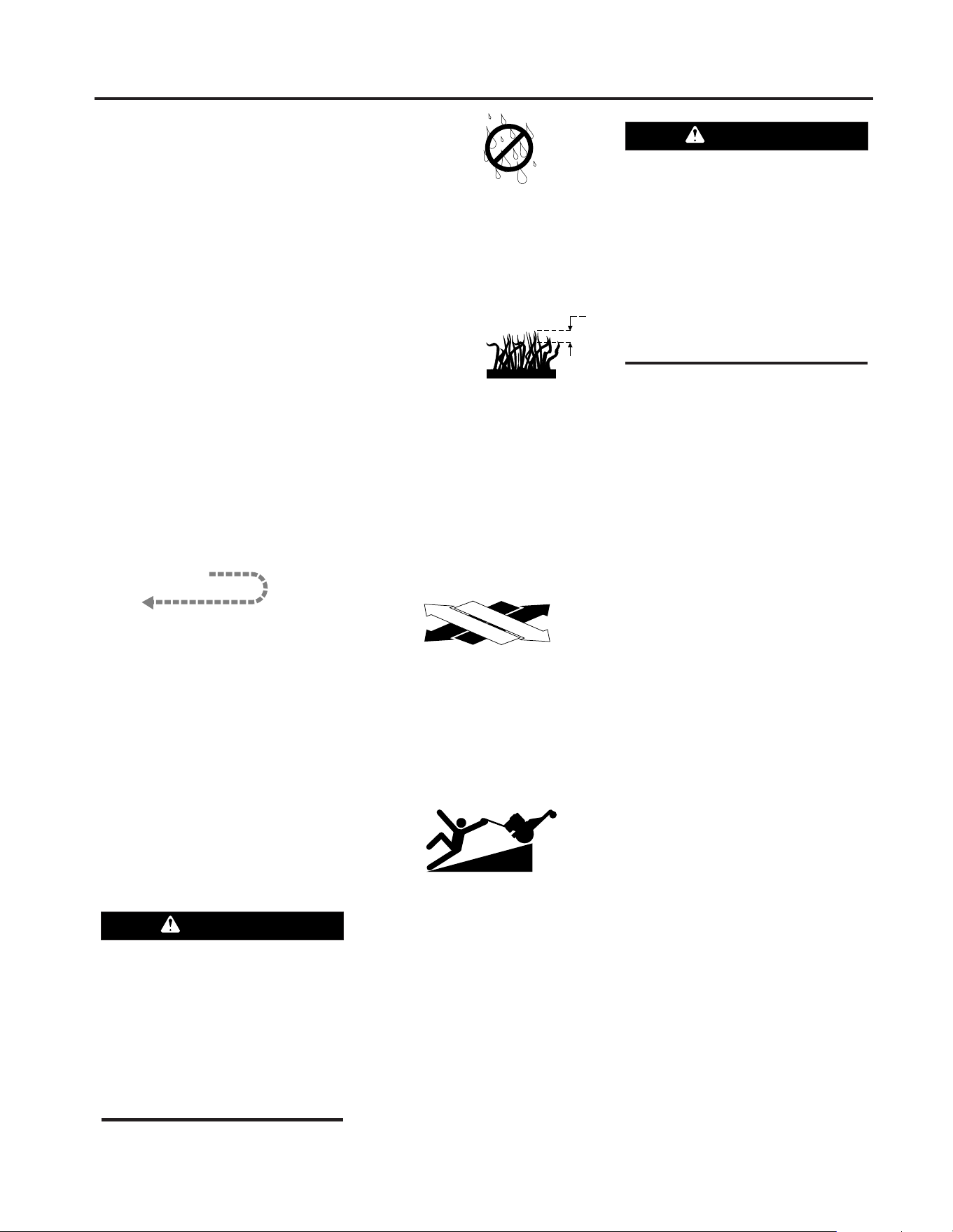
MOWING TIPS AND HINTS
Mow When
Lawn Is Dry
For best results, avoid cutting grass
when it is wet. Wet grass tends to form
clumps which interfere with the cutting
action. The best time to mow is in the
late afternoon or early evening when the
grass is usually dry.
Cut Top 1/3 of
Grass Blades
Cutting more than 1/3 of grass length
may cause the grass to become exces-
sively dry. In tall grass, it may be neces-
sary to mow at a higher setting and then
mow again at the desired height. NOTE:
The cutting height is critical to achieving
a well-groomed lawn. You should exper-
iment with various settings to find that
“just right” cutting height.
Vary Cutting Pattern
Vary the cutting pattern from week to
week to help prevent matting of the
grass. One week, mow from north to
south, the next week mow from east to
west. Overlap several inches when
mowing to obtain an even appearance.
Mowing on Slopes
Do not mow excessively steep slopes
(see WARNING statement that follows).
Slow down and exercise extreme caution
when changing direction on slopes.
Before mowing on slopes, check the en-
gine oil level and make sure that the level
is at the FULL mark. Maintaining a FULL
oil level is particularly important when
operating on slopes as oil can be drained
away from vital engine parts.
Mulching Leaves
• The mower can be used to mow fallen
leaves. The leaf particles filter down into
the lawn and provide added fertilizer.
• The leaves must be dry in order to be
mulched.
• Use a slower ground speed if the
leaves are not mulched into fine parti-
cles.
• If you mulch oak leaves (which add acid
to the soil), add lime to the lawn in the
spring to reduce the acidity of the soil.
Keep Mower Blades Sharp
For best mower performance, keep the
blades sharp. Dull blades will tear,
bruise and split the ends of grass. See
blade sharpening instructions in Section
5: Maintenance.
Clean Mower Frequently
Clean the underside of the mower deck
frequently to remove grass build-up.
See mower cleaning instructions in
Section 5: Maintenance.
Precision Trimming
For precision trimming, use the slow-
est gear and inch the mower along by
“feathering” the Wheel Drive Control
lever. Or, disengage the wheel drive by
releasing the Wheel Drive Control so that
you can manually maneuver the mower
(if needed, put the Gear Select Lever in
neutral so that the wheels turn freely).
Mowing Ditches
If you have to mow ditches, stop the
engine and adjust the cutting height to
its highest setting. Mow in the direction
of the ditch. Mow both sides of the ditch
MAKING TURNS
1
3
To avoid injury or property damage:
• Before mowing, thoroughly inspect
area where mower is to be used and
remove all stones, sticks, wires,
bones, nails and other foreign objects.
• Disengage mower blades before
crossing gravel drives, roads, or side-
walks to prevent blades from throwing
stones or other hazardous objects.
WARNING
To avoid injury or property damage:
• Maximum safe operating angle
is 15
o
.
• Exceeding maximum safe operating
angle may cause tipping or loss of
footing.
• Do not mow wet slopes.
• Mow across slopes, not up and down.
• Exercise extreme caution when
changing direction on slopes.
WARNING
14

15
Section 4: Operation
first, and then mow the bottom. When
mowing ditches, watch out for cans,
bottles, or other debris.
BLADE BRAKE CONTROL TEST
When the Operator Presence Control
is released during operation of the
mower, the engine does not stop, but
the blades should stop within three (3)
seconds. The following test provides a
visual test of whether the Blade Brake
Control System is functioning. Perform
this test before each use of the mower.
1. Park mower on a portion of lawn
which has not been recently mowed.
2. Set the cutting height so the mower
cuts 1/3 of the grass height.
3. Start the engine.
4. Press the Operator Presence Control
down against the handlebar grip and
push the Blade Drive Control fully for-
ward until it stays in the engaged posi-
tion.
5. Put the Gear Select Lever in the No. 1
setting.
6. Engage the wheels with the Wheel
Drive Control and drive the mower for
several feet. Then release the Operator
Presence Control.
A. Look at the lawn just mowed. The
lawn should be cut up to the point
where the Operator Presence Control
was released.
B. Press the Operator Presence Control
against the handlebar grip but DO
NOT re-engage the Blade Drive
Control. Drive the mower forward
for several more feet. Release the
Operator Presence Control and look
at the lawn. The grass should NOT
have been cut. This indicates that
the Operator Presence Control has
disengaged the blade drive and
stopped the blades.
7. If the mower cuts the grass in Step
6-B, the Operator Presence Control is
NOT disengaging the blade drive.
Immediately stop the engine, discon-
nect the spark plug wire, and move the
wire away from the spark plug.
8. Do not use the mower until the Blade
Brake Control System has been in-
spected, adjusted or repaired by an au-
thorized dealer.
To avoid personal injury or property
damage, make sure that the mower is
on grass, and that the test area is clear
of foreign objects and bystanders be-
fore you begin the Blade Brake Control
Test.
If the Operator Presence Control or the
Blade Drive Control are not adjusted
correctly, the blades may continue to
rotate after release of the Operator
Presence Control. If the blades do not
stop within three (3) seconds of release
of the Operator Presence Control, move
the Engine Throttle Control to the STOP
position, disconnect the spark plug
wire, and move the wire away from the
spark plug. Do not operate the mower
until the Blade Brake Control System
has been repaired.
Failure to do this could result in per-
sonal injury or property damage.
WARNING
Carefully read this Section on mower
and engine maintenance and service.
Performing the required maintenance
according to schedule will ensure the
proper performance and long life of your
machine.
NOTE: All references to left, right, front
and rear of the machine are determined by
standing behind the handlebars and facing
the direction of forward travel.
IMPORTANT: REFER TO
MAINTENANCE CHART IN THIS
SECTION FOR A LISTING OF REGU-
LARLY SCHEDULED MAINTENANCE
PROCEDURES.
ENGINE SERVICE
Routine engine service is described
below. For more complete engine ser-
vice information, refer to the engine
manual provided with your machine.
For complete engine service, contact an
authorized engine dealer.
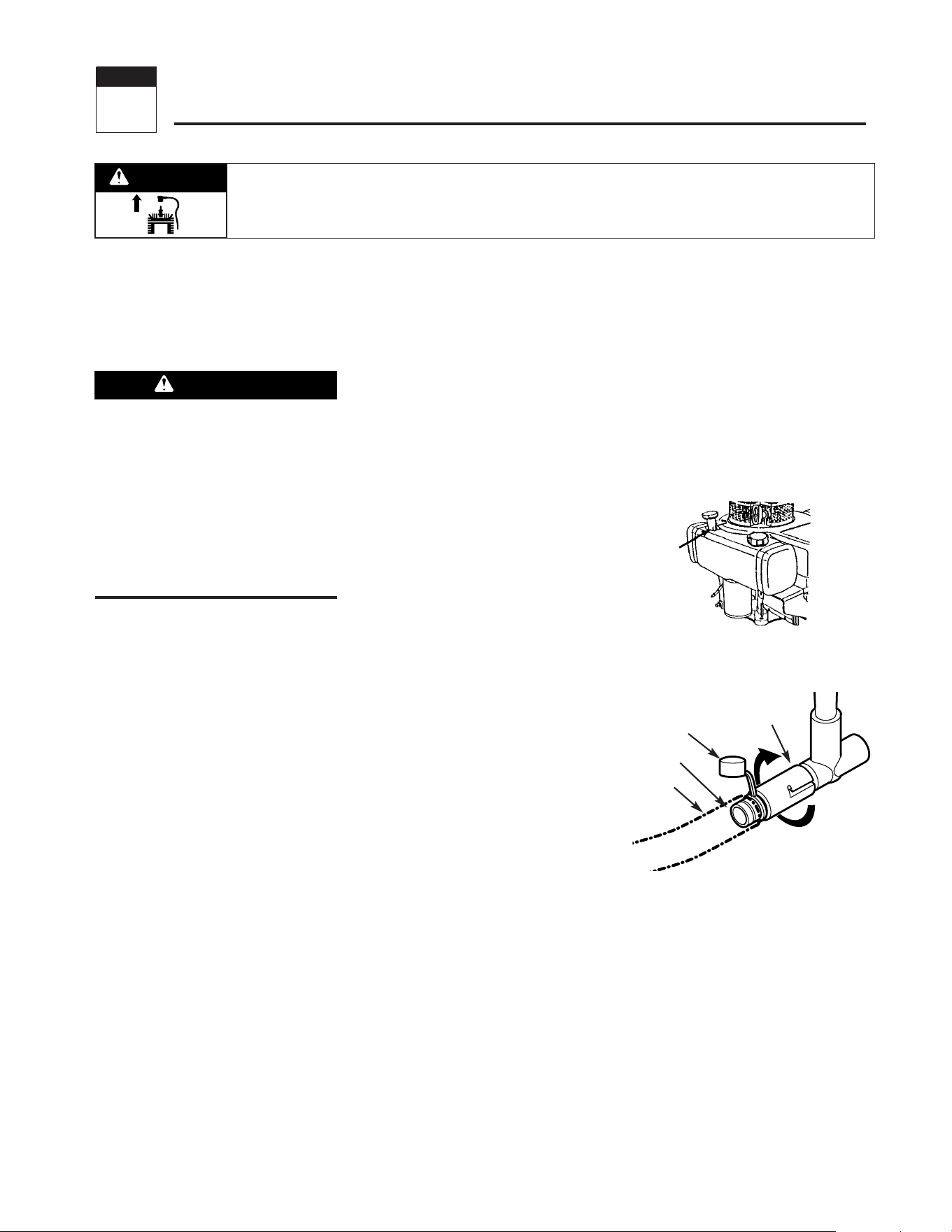
ENGINE OIL
OIL LEVEL: With mower on level
ground, the engine oil level must be be-
tween the "ADD" and "FULL" marks on
the dipstick at all times. Check before
each use and every 5 operating hours.
OIL CHANGE: On a new engine, change
oil after first 2 hours of use, then change
oil regularly as specified on the
Maintenance Chart. Refer to Engine
Owner's Manual for oil capacity.
OIL TYPE: Use clean, high quality deter-
gent oil having an A.P.I. service classifi-
cation of SE, SF or SG. Use no special
additives with oil. Refer to the Engine
Owner’s Manual for recommended SAE
viscosity grades that match the starting
temperature anticipated before the next
oil change.
Checking Oil Level:
1. Park machine on level ground.
2. Stop engine, wait for parts to stop
moving, and disconnect spark plug
wire.
3. Clean area around dipstick (Z, Figure
5-1) to prevent dirt from entering oil fill
hole.
4. Remove dipstick. Oil level must be
between “ADD” and “FULL” marks. Do
not exceed “FULL” mark on dipstick.
5. To add oil, pour slowly into dipstick
opening. While adding, check oil level
frequently by securely replacing dipstick
and removing to read oil level. Wipe dip-
stick clean each time oil level is
checked.
6. After filling to “FULL” mark, securely
replace dipstick.
Changing Oil:
Change oil while engine is still warm
from recent operation. Warm oil flows
more freely and carries away more im-
purities.
1. Stop engine, wait for parts to stop
moving, and disconnect spark plug
wire.
2. Remove dipstick (Z, Figure 5-1).
3. Remove protective cap (A, Figure 5-
2) to expose oil drain port (B).
4. Push oil drain hose (D) (included in
hardware bag with unit) onto oil drain
port. Route other end of hose to an ap-
propriate oil collection receptacle.
5. Twist oil drain fixture (C) to the open
position. Pull out. Drain oil completely.
6. Push in and twist oil drain fixture to
the closed position. Remove drain
hose. Replace protective cap (A).
7. Refill engine with fresh oil and se-
curely replace dipstick.
NOTE: Please dispose of all waste mate-
rials in an ecologically responsible man-
ner. Use proper waste material storage
containers.
Before inspecting, cleaning or servicing
the machine, shut off engine, make
sure that all moving parts have come to
a complete stop, disconnect spark plug
wire and move wire away from spark
plug. Remove ignition key on electric
start models.
Failure to follow these instructions can
result in personal injury or property
damage.
WARNING
Figure 5-1: Briggs and Stratton engine oil
fill.
Z
Figure 5-2: Oil drain.
C
A
B
D
Maintenance
5
Section
Before inspecting, cleaning or servicing the machine, shut off engine, wait for moving parts to stop, disconnect spark
plug wire and move wire away from spark plug. Remove ignition key (electric start models).
Failure to follow these instructions can result in serious personal injury or property damage.
WARNING
16
17
Section 5: Maintenance
ENGINE CLEANING
• Stop engine, wait for parts to stop
moving, disconnect spark plug wire,
and allow engine to cool before in-
specting or cleaning engine.
• Daily or more often, before running en-
gine, remove grass and chaff from recoil
finger guard or rotating screen to prevent
engine damage caused by overheating.
Also keep cooling vanes, governor link-
age, springs and controls free of debris.
• Daily or more often, before running en-
gine, clean muffler area (be sure muffler
is cool) to remove all grass and com-
bustible debris. If engine is equipped
with a spark arrestor screen, remove as-
sembly every 50 hours for cleaning and
inspection. Replace if damaged.
• Grass or chaff may clog engine's air
cooling system, especially after pro-
longed operation cutting tall, dry grass.
See Engine Owner's Manual for instruc-
tions on cleaning underneath the engine
blower housing.
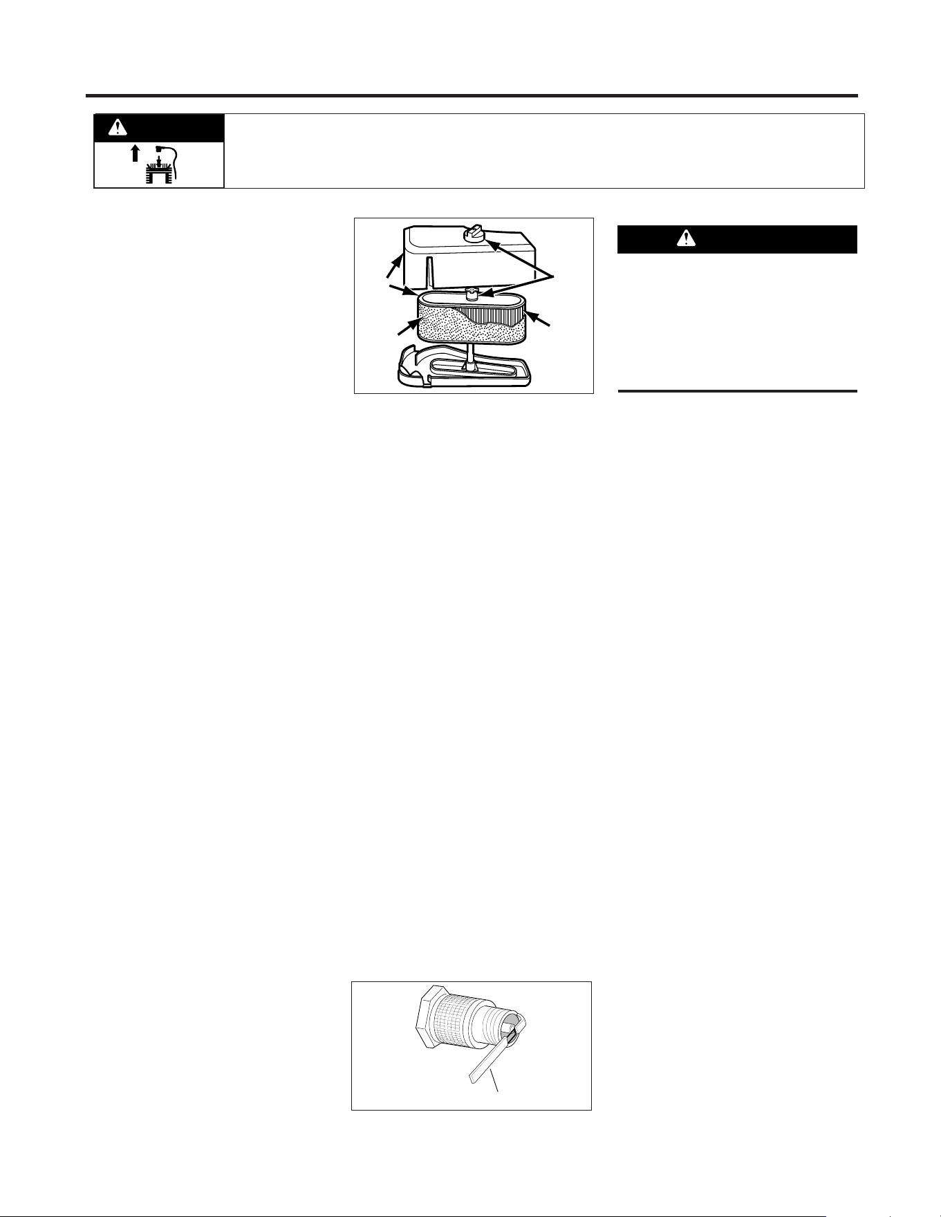
AIR CLEANER SERVICE
Improper air cleaner maintenance can
cause engine damage. Refer to the
Engine Owner's Manual for more com-
plete air cleaner service information.
SERVICE SCHEDULE:
Outer foam pre-cleaner - wash and re-oil
every 25 operating hours or every sea-
son, whichever occurs first.
Inner paper cartridge - clean or replace
every 100 operating hours or every sea-
son, whichever occurs first.
To Service Air Cleaner (Figure 5-3):
1. Stop engine, wait for parts to stop
moving, and disconnect spark plug
wire.
2. Unscrew mounting screws and/or re-
move knobs (D). Remove covers (E).
Remove paper cartridge (B) and foam
pre-cleaner (A). Separate foam pre-
cleaner from paper cartridge.
3. Wash foam pre-cleaner (A) in liquid
detergent and warm water. Squeeze dry
in a clean cloth.
4. Saturate foam pre-cleaner in clean
engine oil. Wrap in clean, absorbent
cloth and squeeze to remove all excess
oil.
5. Replace paper cartridge (B), if
necessary.
6. Reassemble air cleaner components.
Tighten knobs/screws (D) securely.
Secure cover assembly (E) on air
cleaner body.
SPARK PLUG
Inspect the spark plug (Figure 5-4) after
every 100 hours of operation. Be sure
the gap is set at .030". Do not reuse plug
if it is severely worn or damaged.
Best results are obtained with a new
plug. See Engine Owner's Manual to de-
termine proper replacement plug. Use
of incorrect plug can cause engine dam-
age.
NOTE: Do not clean spark plug in ma-
chines which use abrasive grit. Clean
spark plug by scraping or wire brushing,
or washing with a commercial solvent.
BATTERY (if applicable)
Charge battery if unit is to be stored for
longer than three weeks. During the
mowing season, the battery is kept
charged by the charging system on the
engine.
To Charge Battery:
1. Plug charger connector into wire har-
ness connector located below ignition
switch in handlebar console.
2. Plug charger into 120V wall outlet.
(Note that battery charger is designed for
use indoors and should not be exposed to
rain or snow.)
3. Charge battery for 24-48 hours if unit
is to be stored for longer than three
weeks.
4. After charging, unplug charger from
outlet, then unplug charger from con-
nector on wire harness located below
handlebar console.
CARBURETOR
The carburetor is adjusted at the factory.
It should not need to be reset. If black
exhaust is noted, check the air cleaner
first. An over-rich mixture is usually
caused by a poorly serviced or clogged
air cleaner element, not an improperly
adjusted carburetor. If readjustment is
necessary, refer to Engine Owner's
Manual or contact your engine dealer.
Figure 5-3: Briggs and Stratton air cleaner
assembly.
E
D
B
A
Figure 5-4: Spark plug.
.030" Feeler Gauge
Charge battery only with charger sup-
plied with machine. Do not short circuit
battery wires. Remove any jewelry be-
fore working on or near the battery or
electric start system. Failure to follow
these instructions could result in per-
sonal injury or property damage.
WARNING
Before inspecting, cleaning or servicing the machine, shut off engine, wait for moving parts to stop, disconnect spark
plug wire and move wire away from spark plug. Remove ignition key (electric start models).
Failure to follow these instructions can result in serious personal injury or property damage.
WARNING
18
ENGINE STORAGE
If engine will be unused for 30 days or
more, prepare it for storage by following
the recommended procedures found in
the Engine Owner’s Manual.
MOWER SERVICE
The following maintenance/repair proce-
dures can be performed by either the
owner or an authorized service dealer.
See an authorized service dealer for
complete mower service.
TIPPING MOWER FOR SERVICE
When servicing the underside of the
mower for any reason, the mower
should only be tipped backward on its
rear wheels (and securely propped up to
prevent it from falling). Tipping the
mower forward or to either side could
result in damage to engine.
TIP: Before tipping mower, install a
small plastic sandwich style bag under
the gas cap and tighten securely. This
will virtually eliminate any fuel weepage
from the cap. Be sure to remove the
plastic bag before re-using mower.
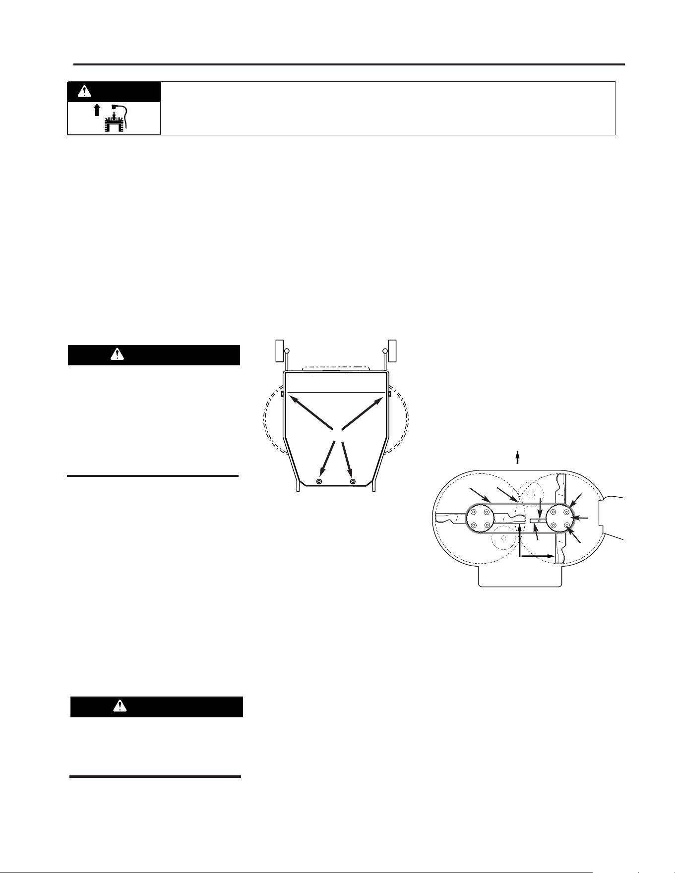
BELT COVER REMOVAL
The belt cover must be removed to per-
form several maintenance procedures.
To Remove Belt Cover:
1. Stop engine, wait for all parts to
stop moving, and disconnect spark
plug wire.
2. Remove four screws (R, Figure 5-5)
and remove cover.
To Reinstall Belt Cover:
1. Position belt cover in place.
2. Secure with the four screws removed
earlier.
BLADE SPINDLE BELT
REPLACEMENT
Follow this procedure to remove and re-
place the blade spindle drive belt (re-
move blade drive belt first; see “Blade
Drive Belt Replacement” in this Section).
1. Stop engine, wait for all parts to
stop moving and disconnect spark plug
wire.
2. Remove belt cover (see “Belt Cover
Removal”).
3. Align sight holes (O, Figure 5-6) in
pulley with spindle housing-to-mower
deck mounting bolts (L).
4. Loosen screw (J) and rotate arm (K)
to the rear.
5. Loosen four mounting bolts (L) se-
curing spindle housing (beneath mower
deck) to mower deck.
6. Slide spindle housing (with pulley at-
tached) toward center.
7. Replace belt (N) with new belt.
IMPORTANT: SET BLADES PERPEN-
DICULAR (90°) TO EACH OTHER.
8. Rotate arm (K) to move spindle
housing and apply tension to belt. Belt
cogs and pulley grooves must mesh to-
gether. When applying moderate finger
tension (8-12 lbs.), belt should deflect
approximately 1/2” (12.7 mm) at (P),
midpoint of deck.
9. Tighten bolts (L) to 15 ft.-lbs. (20.3
Nm). Tighten screw (J).
10. Blades must not contact deck.
Check and readjust as needed.
11. Reinstall blade drive belt and belt
cover (removed earlier).
Section 5: Maintenance
Before servicing underside of mower,
stop engine, wait for all parts to stop
moving, and disconnect spark plug
wire. Remove ignition key from
keyswitch on electric start models.
Failure to follow this instruction could
result in personal injury or property
damage.
WARNING
Do not operate unit without belt cover
installed. Failure to follow this instruc-
tion could result in personal injury or
property damage.
WARNING
Figure 5-5: Belt cover removal.
R
BLADES
MUST BE PERPENDICULAR
TO EACH OTHER
FRONT
Figure 5-6: Blade Spindle Belt.
N
P
J
O
M
L
K
Before inspecting, cleaning or servicing the machine, shut off engine, wait for moving parts to stop, disconnect spark
plug wire and move wire away from spark plug. Remove ignition key (electric start models).
Failure to follow these instructions can result in serious personal injury or property damage.
WARNING
19
Section 5: Maintenance
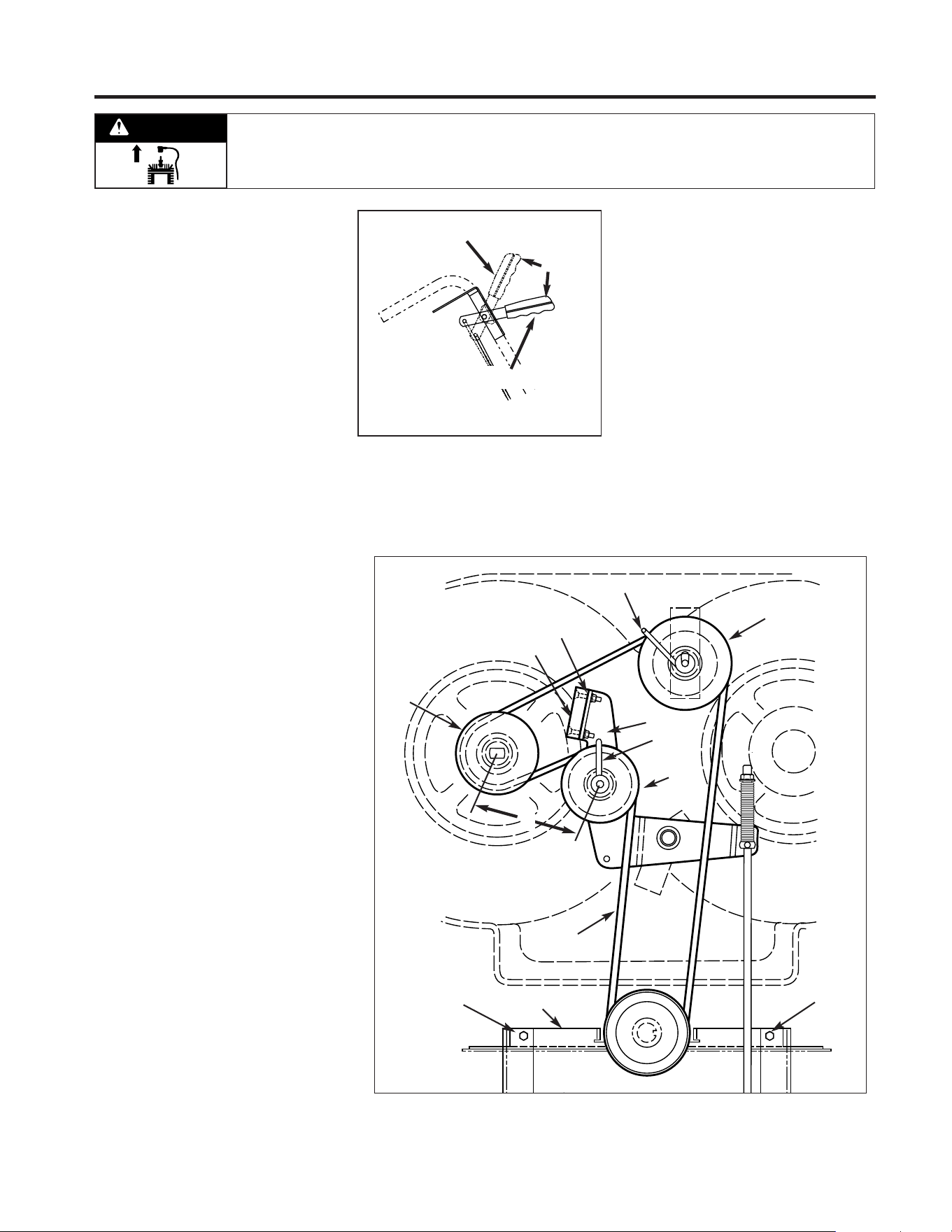
BLADE DRIVE BELT
REPLACEMENT
Follow this procedure to remove and re-
place the blade drive belt. An assistant
will be needed.
To Remove Belt:
1. Stop engine, wait for all parts to
stop moving, and disconnect spark
plug wire.
2. Disengage blade drive control (Figure
5-7) by releasing all controls on the
mower.
3. Remove belt cover (see “Belt Cover
Removal”).
4. Loosen belt guides (B and C,
Figure 5-8).
5. Move flap bracket (N, Figure 5-8) out
of the way by loosening two screws (M).
6. Remove belt (A, Figure 5-8) from
around sheaves.
To Install Belt:
1. Route belt (A, Figure 5-8) around
sheaves as shown.
2. Have an assistant hold down
Operator Presence Control and then
push the Blade Drive Control forward
until it latches in place (Figure 5-7).
3. With the Blade Drive Control lever en-
gaged, adjust and tighten belt guide (B)
to 1/32 - 1/16" away from tensioned
belt. (Be sure that belt does not contact
belt guide when belt is under tension.)
Secure belt guide (C) rotated into posi-
tion as shown in Figure 5-8.
4. Disengage Blade Drive Control.
5. Re-tighten two screws (M, Figure
5-8) that secure flap bracket (N).
6. Reinstall belt cover securely.
Figure 5-7: Blade Drive Control.
RIGHT VIEW
Blade Drive Disengaged
Blade Drive Engaged
A
Figure 5-8: Blade drive.
B
J
C
I
H
G
K
L
A
X
M
M
N
Before inspecting, cleaning or servicing the machine, shut off engine, wait for moving parts to stop, disconnect spark
plug wire and move wire away from spark plug. Remove ignition key (electric start models).
Failure to follow these instructions can result in serious personal injury or property damage.
WARNING
20
Section 5: Maintenance
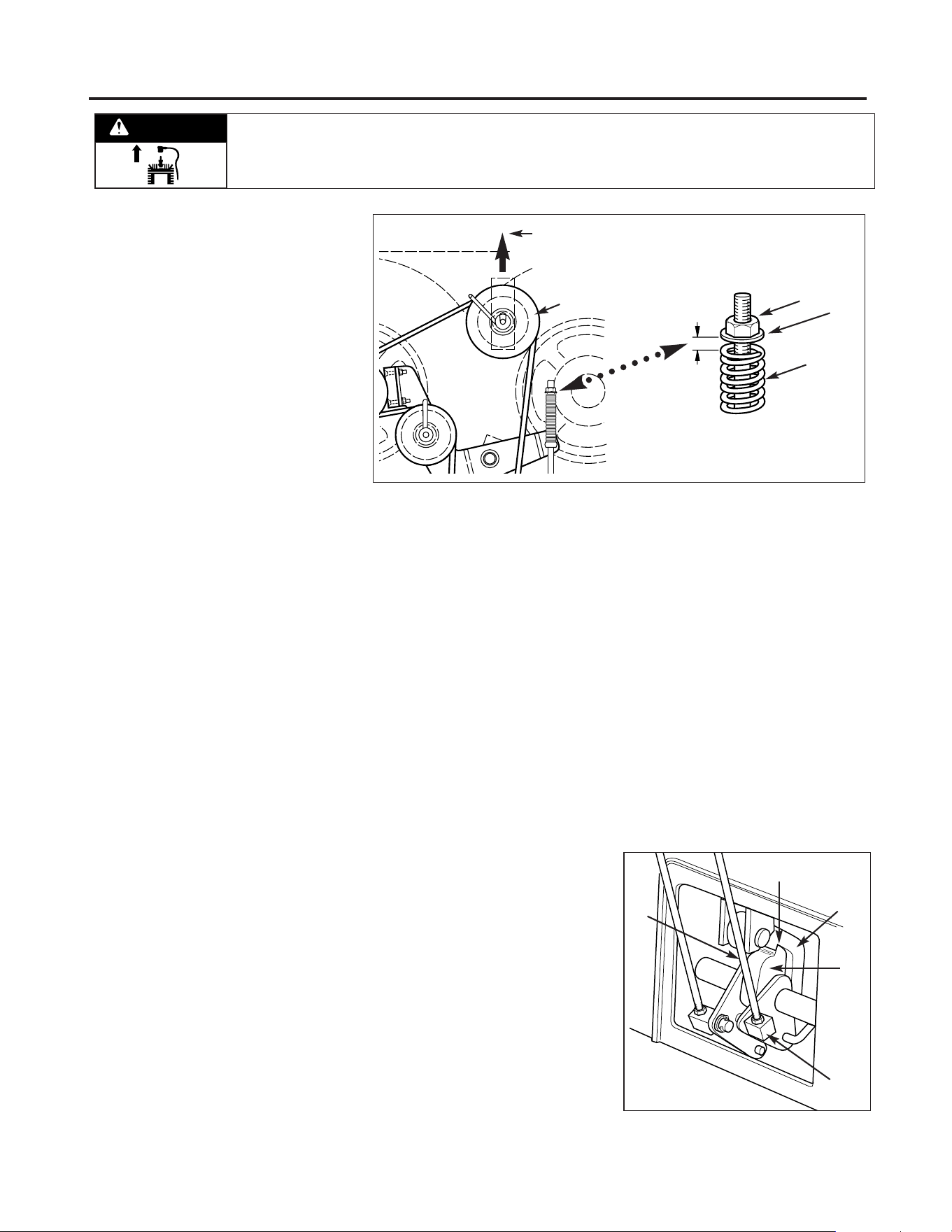
BLADE BRAKE REPLACEMENT
Follow this procedure to install a new
blade brake.
To Remove Blade Brake:
1. Stop engine, wait for all parts to
stop moving, and disconnect spark
plug wire.
2. Remove belt cover as described in
“Belt Cover Removal” instructions.
3. Remove hardware (G, Figure 5-8)
securing blade brake (H).
4. Remove old brake (H) from idler
arm (I).
To Install Brake:
1. Position new brake (H) in place on
idler arm (I).
2. Center brake in sheave groove and
secure brake (H) with hardware (G) re-
moved earlier.
3. Reinstall belt cover securely.
4. Test operation of blade brake (see
“Blade Brake Control Test” in Operation
section).
BLADE DRIVE BELT
ADJUSTMENT
If the blade drive belt is slipping due to
lack of belt tension, follow the steps
below.
1. Stop engine, wait for all parts to
stop moving, and disconnect spark
plug wire.
2. Remove belt cover as described in
“Belt Cover Removal” instructions.
3. With mower on level ground, adjust
blade cutting height at about 3" (mea-
sure from ground to flat portion of
blade).
4. With the Blade Drive Control (Figure
5-7) in the disengaged position, set a
gap of 1/8" between the spring (F, Figure
5-9) and flat washer (E) by adjusting the
nut (D).
5. Reinstall the belt cover securely.
6. Test the operation of the blade brake
(see “Blade Brake Control Test” in the
Operation section).
7. If the drive belt slips during opera-
tion, it may be necessary to
relocate idler (J, Figure 5-9) in the slot
provided in the mounting bracket. With
the engine stopped and the spark plug
wire disconnected, loosen the hardware
on the idler (J) and slide it forward to
take up slack in the belt.
8. Engage the blade drive and measure
the distance (X, Figure 5-8) between the
centers of pulleys (K) and (L). The dis-
tance should be 5-1/2 to 5-5/8". After
obtaining the correct dimension, rein-
stall the belt cover securely and test the
operation of the blade brake.
BLADE DRIVE CONTROL LEVER
ADJUSTMENT
Make the following adjustment if the
Blade Drive Control Lever releases dur-
ing operation.
1. Stop engine, wait for all parts to
stop moving, and disconnect spark
plug wire.
2. Engage the Operator Presence
Control and the Blade Drive Control.
Without releasing the controls, look in-
side the cutout at the rear of the frame
and make sure the Operator Presence
Control latches (A and B, Fig. 5-10) are
fully engaged at point (C). If they are not
fully engaged, improper operation or
premature wear could result. To adjust,
loosen hex nut (D) and shorten length of
control rod (E). To avoid over-adjusting,
turn rod only 1 to 2 turns per adjust-
ment.
3. Tighten hex nut securely after adjust-
ing control rod.
4. Test by releasing the Operator
Presence Control. If properly adjusted,
the Blade Drive Control will disengage
when the Operator Presence Control is
released. Re-adjust as necessary by
repeating Steps 2 and 3.
Figure 5-9: Blade drive adjustment.
1/8"
J
D
E
F
Adjust idler in direction
of arrow to tighten blade
drive belt
Figure 5-10: Blade Drive Control Lever
adjustment.
B
E
D
A
C
Before inspecting, cleaning or servicing the machine, shut off engine, wait for moving parts to stop, disconnect spark
plug wire and move wire away from spark plug. Remove ignition key (electric start models).
Failure to follow these instructions can result in serious personal injury or property damage.
WARNING
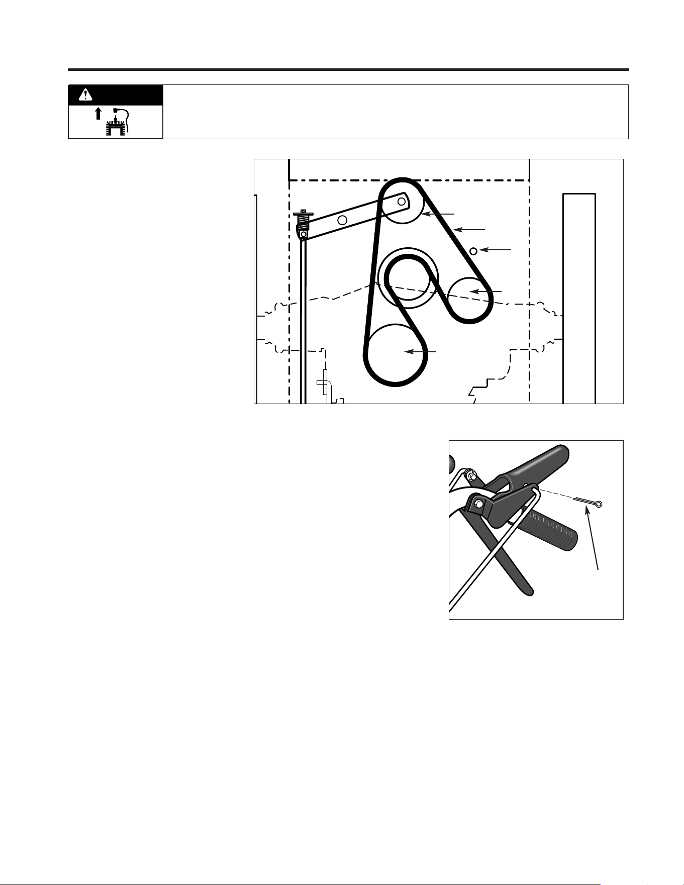
21
Section 5: Maintenance
WHEEL DRIVE BELT
REPLACEMENT
Follow this procedure to replace the
wheel drive belt.
1. Stop engine, wait for all parts to
stop moving, and disconnect spark
plug wire.
2. Release all mower controls.
3. Remove belt cover as described in
“Belt Cover Removal” instructions.
4. Locate wheel drive belt (O, Figure 5-
11) and remove it from top sheave of
engine sheave, backsided idlers (P and
Q) and transmission sheave (R).
5. Install new belt as shown in Figure 5-
11. Belt must be installed “inside out ”–
“V” side of belt lies against
engine sheave only. Flat side of belt lies
against transmission sheave (R) and
back-sided idlers (P and Q).
6. Make sure belt is inside belt guide (S,
Figure 5-11).
7. Reinstall belt cover securely.
8. An adjustment to the drive belt may
be necessary. See “Wheel Drive Belt
Adjustment” in this Section.
WHEEL DRIVE BELT
ADJUSTMENT
The wheel drive belt requires an adjust-
ment if loss of drive belt tension (slip-
page) occurs. This is most noticeable
when more traction is required (such as
going up slopes).
To Test Wheel Traction:
1. Park machine on a paved (concrete,
etc.) surface with front edge up against
a sturdy wall, fence, etc.
2. Put Gear Select Lever in No. 1 setting.
IMPORTANT: DO NOT PARK AGAINST A
PAINTED OR SIDED WALL. TESTING
THE WHEEL DRIVE SYSTEM REQUIRES
MACHINE TO BE FORCIBLY PUSHED
AGAINST WALL. DAMAGE TO PAINT OR
SIDING COULD RESULT.
3. With engine running, and machine
placed firmly up against wall, hold down
Operator Presence Control and fully en-
gage wheel drive by squeezing Wheel
Drive Control until it contacts handlebar.
4. Wheels should slip on paved surface.
If they do not, an adjustment is required.
To Adjust Wheel Drive Belt:
1. Stop engine, wait for all parts to
stop moving, and disconnect spark
plug wire.
2. Remove cotter pin (A, Figure 5-12A)
from upper end of Wheel Drive Control
rod. Slide rod out of lever assembly.
3. Loosen jam nut (D, Figure 5-12).
4. Thread rod (E, Figure 5-12) one or
two turns clockwise for more tension or
counterclockwise for less tension.
5. Insert rod back into hole in Wheel
Drive Control lever and install cotter pin.
Bend ends of cotter pin to secure.
6. Retest wheel traction. Repeat adjust-
ment procedure, if necessary. Most
comfortable operation will be obtained
when the adjustment allows the lever to
just make contact with the handgrip as
sufficient wheel traction is achieved.
When adjustment is complete, tighten
jam nut (D) firmly against block (B).
WHEEL BRAKE ADJUSTMENT
This adjustment may be required if the
machine does not hold on a hill with the
Operator Presence Control disengaged,
or if the brake drags with the Operator
Presence Control engaged and the trans-
mission in neutral.
1. Stop engine, wait for all parts to
stop moving, and disconnect spark
plug wire.
2. Disengage (release) the Operator
Presence Control (M, Figure 5-13).
Figure 5-11: Wheel drive belt replacement.
S
O
Q
P
R
Figure 5-12A
A
Before inspecting, cleaning or servicing the machine, shut off engine, wait for moving parts to stop, disconnect spark
plug wire and move wire away from spark plug. Remove ignition key (electric start models).
Failure to follow these instructions can result in serious personal injury or property damage.
WARNING
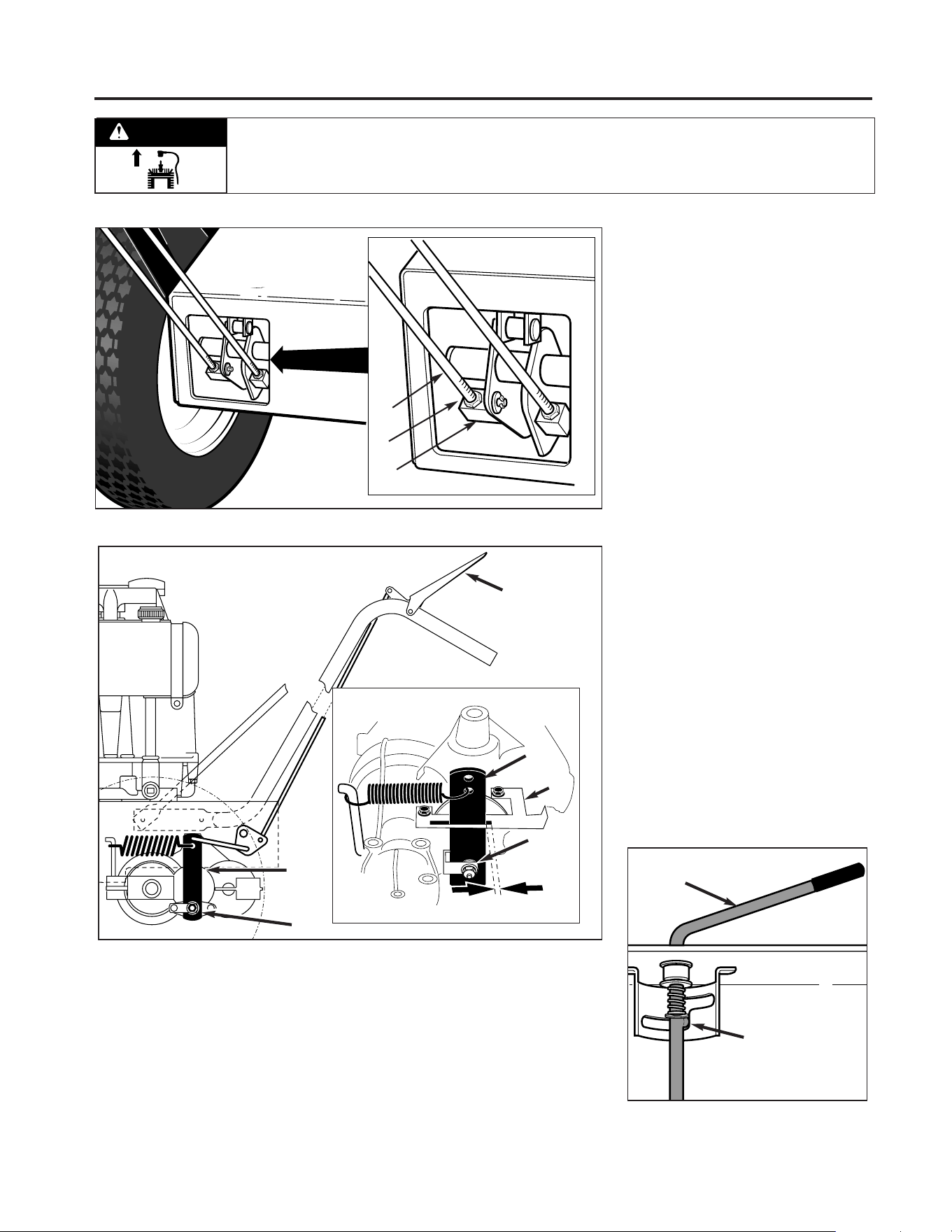
Section 5: Maintenance
3. Slowly adjust at nut (O), if necessary,
until the distance between the back of
brake arm (N) and bracket (P) is 3/8”-
5/16". Use small adjustments (1/4 turn
maximum). NOTE: It may be necessary
to relieve spring tension when decreas-
ing distance. To do so, have an assis-
tant engage the Operator Presence
Control while you adjust the nut.
TRANSMISSION NEUTRAL
ADJUSTMENT
Follow this procedure to adjust neutral
on the transmission.
1. Stop engine, wait for all parts to
stop moving, and disconnect spark
plug wire.
2. Rotate shift rod (I, Figures 5-14 and
5-15) clockwise until it stops in the neu-
tral (N) position (from forward gear
positions).
3. Hold down Operator Presence Control
(M, Figure 5-13) and push unit forward
and backward. Unit should move freely.
If not, continue with Step 4.
4. Remove cotter pin securing shift link
(P, Figure 5-15) to shift rod (I).
5. Move shift arm (X) back and forth as
necessary into each detent until trans-
mission is in neutral. NOTE: Moving
shift arm (X) clockwise all the way to the
left, and then one notch back counter-
clockwise, should put transmission into
neutral. When transmission is in neutral,
unit will move freely when pushed while
holding the Operator Presence Control
lever down. If transmission is NOT in
neutral, there will be a slight drag on the
wheels when pushing unit.
6. When shift arm (X) is in neutral posi-
tion, rotate shift link (P) until hooked
end fits back into hole in bottom end of
shift rod (I). NOTE: Shift rod (I) must be
held in the neutral position (see Figure
5-14) while shift link (P) is adjusted.
7. Secure shift link (P) into shift rod (I)
with cotter pin removed earlier.
8. Re-check neutral by pushing unit
back and forth and shifting lever (I) from
reverse to neutral. A small fine-tune
adjustment may be required.
Figure 5-12: Wheel drive belt adjustment.
E
D
B
Figure 5-13: Wheel brake adjustment.
Figure 5-14: Lever in neutral (N) position.
M
N
O
N
O
P
I
Detent for
Neutral Position
3/8"-
5/16"
Before inspecting, cleaning or servicing the machine, shut off engine, wait for moving parts to stop, disconnect spark
plug wire and move wire away from spark plug. Remove ignition key (electric start models).
Failure to follow these instructions can result in serious personal injury or property damage.
WARNING
22
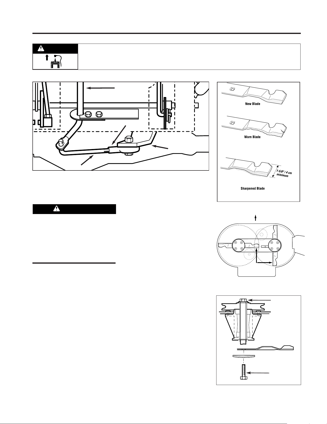
Section 5: Maintenance
MOWER BLADES
Examine mower blades before operation.
For efficient mowing, cutting edges of
blades should always be kept sharp.
Check for blade wear or damage. See
Figure 5-16. Replace a severely worn or
damaged blade with a new one.
To Inspect Blades:
1. Stop engine, wait for all parts to
stop moving, and disconnect spark
plug wire.
2. Tip mower on rear wheels by follow-
ing instructions “Tipping Mower For
Service” in this Section of Manual.
To Remove Blades:
Remove bolt (Figure 5-18) and
washer(s). Remove mower blade.
To Sharpen Blades:
Grind or file the same amount from each
blade end to maintain blade balance. An
unbalanced mower blade produces ex-
cessive vibration and may damage spin-
dle bearings. Sharpen cutting edge
straight across, parallel to rear edge of
mower blade. See Figure 5-16. After
sharpening, blade balance must be
checked.
IMPORTANT: PROFESSIONAL SHARP-
ENING SERVICES OR YOUR AUTHO-
RIZED DEALER ARE EQUIPPED TO
SHARPEN MOWER BLADES SAFELY.
To Install Blades:
Blades must be installed perpendicular
to each other (see Figure 5-17).
Install mower blade as shown in Figure
5-18 with flat side down. Install washer
on bolt. Tighten bolts to a torque value
of 35 ft. lbs. (47 Nm).
NOTE: If top bolt is removed, reinstall
using LOCTITE #242 thread sealant.
Figure 5-15: Transmission neutral (N) adjustment.
P
I
X
Y
Mower blades are sharp.
• When working near blades, wear
heavy leather gloves or wrap blades in
thick rags to protect yourself from the
sharp edges.
• Wear eye protection when sharpening
blades.
WARNING
Figure 5-16: Blade Inspection
Replace if separation
begins to form.
Sharpen blade cutting edge straight
across, parallel to blade trailing edge.
Figure 5-17
BLADES
MUST BE PERPENDICULAR
TO EACH OTHER
FRONT
Figure 5-18: Blade spindle.
Torque to
35 Ft. Lbs.
Torque to
35 Ft. Lbs.
Mower Blade
Washer
Bolt
Before inspecting, cleaning or servicing the machine, shut off engine, wait for moving parts to stop, disconnect spark
plug wire and move wire away from spark plug. Remove ignition key (electric start models).
Failure to follow these instructions can result in serious personal injury or property damage.
WARNING
23

24
Section 5: Maintenance
CLEANING UNDERSIDE OF
MOWER DECK
Frequently check, and clean if necessary,
the underside of the mower deck. Grass
build-up in this area can affect the cut-
ting performance. Before inspecting or
cleaning, make sure that the engine is
shut off and the spark plug wire is
disconnected from the spark plug.
Inspection/Cleaning of Mower Deck:
1. Stop engine, wait for all parts to
stop moving, and disconnect spark
plug wire.
2. Tip mower on rear wheels by follow-
ing instructions "Tipping Mower For
Service" in this Section.
3. Use a plastic or metal scraper to
remove grass build-up from deck or
blades. If needed, spray with a garden
hose.
LUBRICATION
Oil and grease the mower according to
the recommendations listed in the
Lubrication Chart on the next page.
• Stop engine, wait for all parts to stop
moving, and disconnect spark plug
wire before performing any lubrication
procedures.
• The transmission has been factory
sealed and requires no lubrication. If a
leak should develop, contact the factory
or your local authorized dealer for
service information.
OFF-SEASON STORAGE
• Stop engine, wait for all parts to stop
moving, and disconnect spark plug
wire before performing any storage
procedures. Review the storage safety
rules in the Safety Section of this
Manual.
• If engine will be unused for 30 days or
more, prepare it for storage by following
the recommended procedures found in
the Engine Owner's Manual.
• Inspect all parts for damage, breakage,
and wear. Tighten or replace fasteners.
Contact the factory or your local
authorized dealer for factory-approved
replacement parts.
• Clean the exterior of the mower thor-
oughly and touch up all chipped or
scratched surfaces to prevent rust from
forming.
Mower blades are sharp.
When working near blades, wear heavy
leather gloves or wrap blades in thick
rags to protect yourself from the sharp
edges.
WARNING
Never store machine with fuel in the
fuel tank inside a building where fumes
may reach an open flame or spark, or
where ignition sources are present
such as hot water and space heaters,
furnaces, clothes dryers, stoves, elec-
tric motors, etc.
WARNING
Before inspecting, cleaning or servicing the machine, shut off engine, wait for moving parts to stop, disconnect spark
plug wire and move wire away from spark plug. Remove ignition key (electric start models).
Failure to follow these instructions can result in serious personal injury or property damage.
WARNING

25
Section 5: Maintenance
Lubrication Chart
LUBRICATION TYPE
Change Oil
Change Oil
(Lubrication Intervals Vary
with Operating Conditions
and Type of Oil Used)
Grease
Light Oil
Grease
ITEM
Engine Crankcase
Front Wheel Bearings
Control Linkages/Pivots
Transmission Output Shaft
INTERVAL
First 2 hours
25-50 hours
50 hours
25 hours
100 hours or Annually
AMOUNT REQUIRED
See Engine Manual
Change oil more often
in extremely dirty or
dusty conditions.
1-3 Strokes*
A Few Drops
1-3 Strokes*
* A hand-type grease gun is recommended.
Before inspecting, cleaning or servicing the machine, shut off engine, wait for moving parts to stop, disconnect spark
plug wire and move wire away from spark plug. Remove ignition key (electric start models).
Failure to follow these instructions can result in serious personal injury or property damage.
WARNING

26
Section 5: Maintenance
*Interval describes running time.
**A hand-type grease gun is recommended when greasing your
unit. High-pressure type grease guns could cause damage to fit-
tings/seals.
***Consult engine manual for more detailed engine service infor-
mation.
****Clean more often under dusty conditions or when airborne
debris is present. Replace air cleaner parts, if very dirty.
ATTENTION! This chart describes service guidelines only. It does not provide complete service information. Complete service
is available from your authorized mower or engine dealer. Before performing any of the maintenance procedures, refer to the
appropriate information contained in this Manual or the Engine Owner’s Manual for the correct safety precautions and mainte-
nance procedures.
ITEM
Mower Blade
Loose or Missing Hardware
Belts
Engine Oil Level
Controls
Mulching Cover
Engine Oil
Engine Oil***
Foam Air Filter****
Mower Blade(s)
Control Linkages and Pivots
Engine Oil***
Blade Drive Belt Adjust
Engine Cooling Fins
Grease Fittings**
Air Filter Element****
Spark Plug
Transmission Output Shaft
Linkages
Belts
Front Wheel Bearings
SERVICE
As Required
Tighten or Replace
Check
Check
Check for Proper Operation
Check for Proper Cover Installation
Change
Change
Clean
Sharpen and Balance
Lube with Light Oil
Change
Adjust Tension
Clean
Grease
Replace
Clean/Replace, Re-gap
Grease
Adjust
Check/Replace, Adjust
Grease
Maintenance Chart
INTERVAL*
Each use
1st 2 hours
25 hours
50 hours
Annually or 100 hours
Monthly
Annually or 50 hours
Before inspecting, cleaning or servicing the machine, shut off engine, wait for moving parts to stop, disconnect spark
plug wire and move wire away from spark plug. Remove ignition key (electric start models).
Failure to follow these instructions can result in serious personal injury or property damage.
WARNING

27
Engine does not turn over.
Engine turns over but will not start.
Engine starts only after repeated tries.
Engine runs roughly.
Engine stalls in a few seconds.
Engine runs but unit does not move.
Wheel drive always engaged.
Engine stalls when hot.
Engine overheats.
Engine does not shut off.
Blade drive inoperative.
Blade drive always engaged.
Battery not charging (if applicable).
Poor mowing performance.
Blade does not stop when Operator
Presence Control is released.
Excessive vibration.
Engine malfunction (refer to engine manual). ••••• ••• •
Improperly adjusted drive linkage. •• •• • • •
Dirty engine cooling fins or flywheel screen. •
Faulty ignition. ••••• • •
Faulty spark plug. •••• •
Empty fuel tank. ••••
Battery or charging malfunction (if applicable). •• • •
Improperly adjusted or dirty carburetor. •••• •
Improper oil level. ••
Dirty air cleaner element. ••• •
Improperly adjusted choke (if applicable). •••• •
Transmission malfunction. ••
Improperly adjusted drive linkage. •• •• •
Broken, loose or worn belt(s). ••• •••
Dull blade(s). ••
Throttle control out of adjustment. •• •
Blade/brake system out of adjustment. •• •
Blade(s) out of balance. ••
Loose hardware. •• •
Troubleshooting Chart
ATTENTION! This table describes service
guidelines only. It does not provide com-
plete service information. Complete service
is available from your authorized mower or
engine dealer. Before performing any of the
corrections in this table, refer to the appro-
priate information contained in this Manual
or the Engine Owner’s Manual for the cor-
rect safety precautions and operating or
maintenance procedures.
Possible cause
Symptom
Section 5: Maintenance
Before inspecting, cleaning or servicing the machine, shut off engine, wait for moving parts to stop, disconnect spark
plug wire and move wire away from spark plug. Remove ignition key (electric start models).
Failure to follow these instructions can result in serious personal injury or property damage.
WARNING
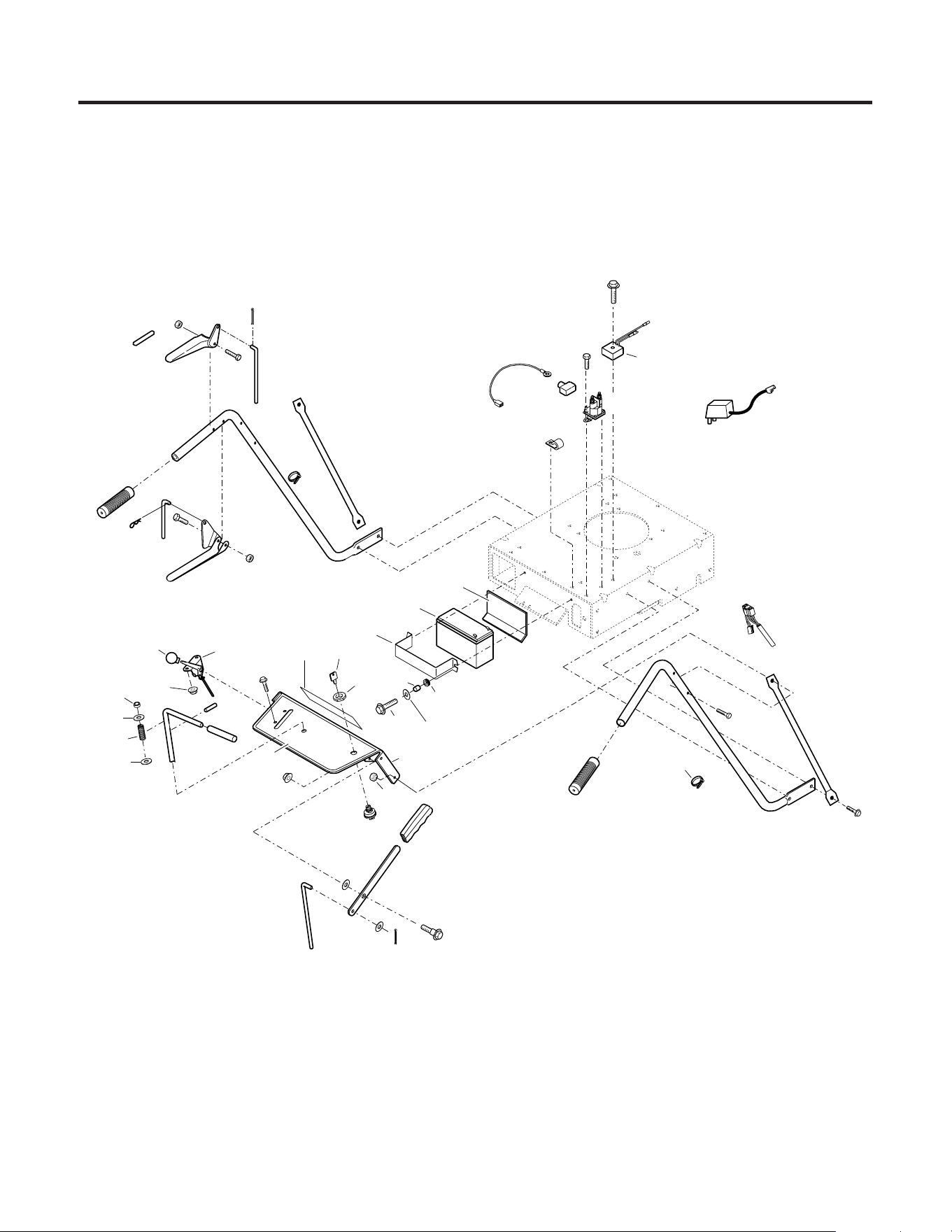
28
Wide-Cut Combination Mower
111
112
78
115
116
114
113
118
72
117
119
120
33
122
123
124
80
121
84
403
126
11
129
114
97
97
142
146
135
148
134
17
141
140
139
172
19
137
138
130
131
92
16
19
116
142
113
143
110
145
125
301
82
136
153
300
SEE PAGES 4 AND 5
FOR BREAKDOWN.
43
114
16
113
96
68
124
HANDLEBAR AND CONSOLE ASSEMBLY

29
Models 753B, E753B
11 1186393 Flange Locknut, 3/8-16........................... 1
16 1185147 Cotter Pin, 3/32 x 5/8 ............................. 2
17 1721252 J-Clip...................................................... 1
19 1107382 Flat Washer, 5/16 ................................... 4
33 1186389 Flange Locknut, 1/4-20........................... 2
43 1702646 Flat Washer, 1/2 ..................................... 1
68 1769888 Upper Blade Rod .................................... 1
72 1773607 Upper Transmission Rod........................ 1
78 1769872 Upper Brake Rod.................................... 1
80 1769874 Shift Rod ................................................ 1
82 1724492 Thread Cut. Screw, 1/4-20 x 1/2 (B)....... 2
84 1186308 Flange Lock Screw, 1/4–20 x 1/2 ........... 2
92 1703051 Shoulder Bolt ......................................... 1
96 1185279 Roll Pin, 1/4 x 2-1/4 ............................... 1
97 1915545010 Brace, Handlebar (A) (B) ........................ 2
110 1186329 Flange Lock Screw, 5/16 x 3/4 ............... 4
111 1770445001 Control Handle ....................................... 1
112 777I00001 Operator Presence Control Decal ........... 1
113 1915793 Screw, 1/4–20 x 1-3/4, Grade 8 ............. 6
114 1734398 Locknut, 1/4–20 ..................................... 2
115 1764922010 Left Handlebar (A) (B) ............................ 1
116 1703539 Handle Grip ............................................ 2
117 1773605001 Control Handle ....................................... 1
118 1717897 Hair Pin, 5/64 ......................................... 1
119 1768191 Throttle Control ...................................... 1
120 1737118 Knob....................................................... 1
121 1737041 Handle Grip ............................................ 1
122 1715716 Nylon Bushing........................................ 1
123 1721492 Compression Spring............................... 1
124 736-0326 Flat Washer, 1/2 ..................................... 1
125 777S00003 Warning Decal (A) ................................. 1
126 777D06080 Logo Decal (A) (B) ................................. 1
129 1734196 Ignition Switch (B) ................................. 1
130 1764984 Handle Grip ............................................ 1
131 1768223 Mower Engage Lever.............................. 1
134 1752137 Solenoid (B) ........................................... 1
135 1747027 Thread-Cut. Screw, 1/4–20 x 1-1/2 (B).... 1
136 1768464 Regulator ............................................... 1
137 1749778 Spacer (B) .............................................. 2
138 1769080 Grommet (B) .......................................... 2
139 1915696010 Battery Bracket (B) ................................. 1
140 1915750 Battery (B).............................................. 1
141 1769081 Battery Pad (B)....................................... 1
142 1735531 Plastic Tie............................................... 5
143 1764923010 Right Handlebar (A) (B).......................... 1
145 1915758 Wiring Harness (B)................................. 1
146 1915759 Lead (B) ................................................. 1
148 1734364 Boot (B).................................................. 1
153 1768449 Battery Charger (shipped loose) (B)....... 1
172 1724491 Screw, 5/16-18 x 3/4"............................. 1
300 1753986 Ignition Key (B) ...................................... 1
301 1768640 Console Assembly (Incl. Ref. 125) (A) ... 1
1768493 Console Assembly (Incl. Ref. 125) (B) ... 1
403 1770592 Nut, Ignition Switch ............................... 1
Ref. Part Description Qty.
Ref. Part Description Qty.
(A) Model 753B
(B) Model 34343
HANDLEBAR AND CONSOLE ASSEMBLY
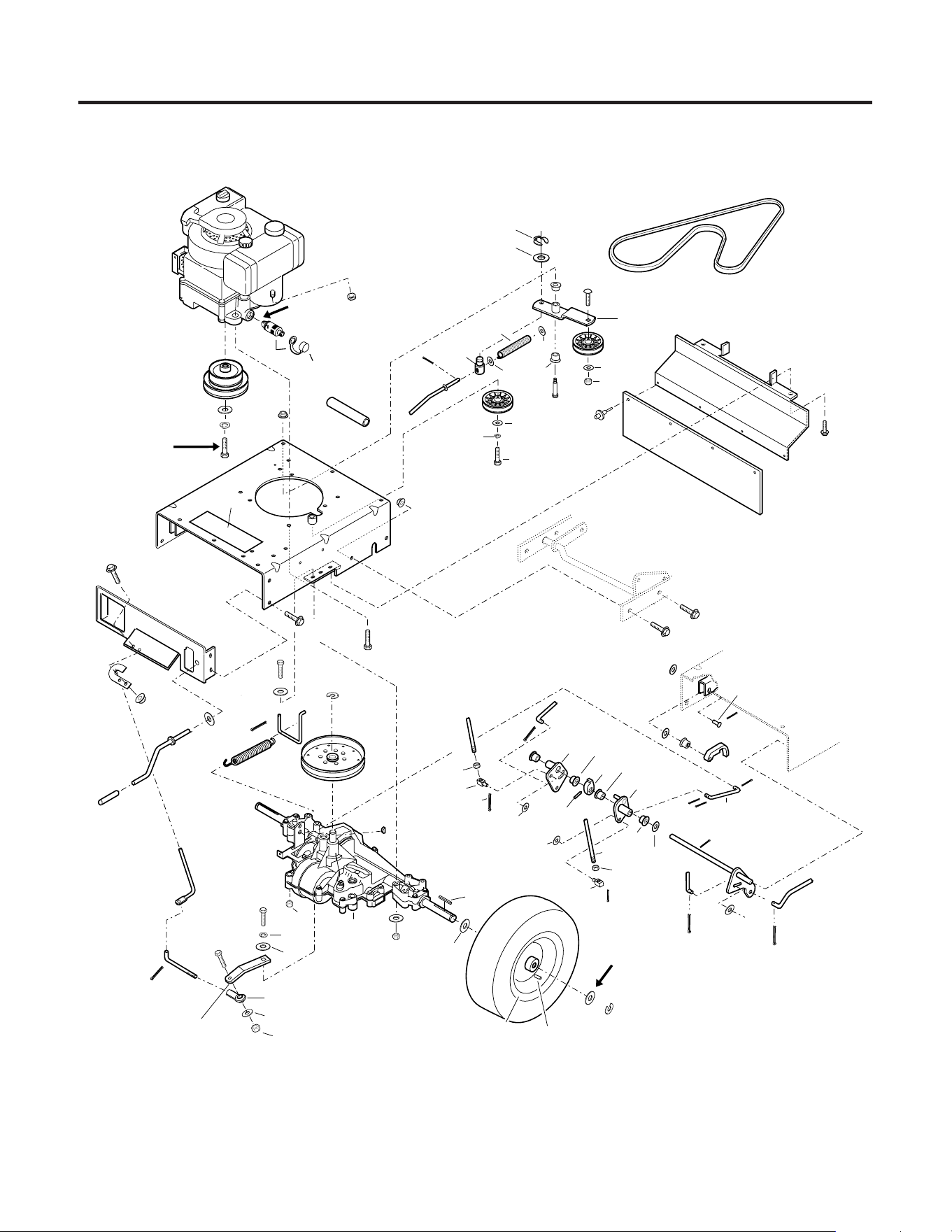
30
1
9
10
2
3
403
4
11
84
83
33
177
79
19
5
16
76
75
61
60
56
80
71
16
67
70
69
28
65
63
66
62
64
29
31
57
19
54
51
303
53
50
68
58
16
42
39
87
11
32
36
28
27
15
23
21
19
72
49
48
16
16
15
81
19
19
78
49
48
16
23
25
26
27
28
30
90
91
(RIGHT REAR ONLY)
7
302
85
TORQUE TO
40 FT. LBS.
LOCTITE IN PLACE
55
APPLY
SEALANT
AS
REQUIRED
8 (CAP ONLY)
304
305
23
41
23
168
170
23
18
167
13
14
12
172
16
44
23
171
16
18
16
19
159
403
402
169
ITEMS 316 & 307
PAGES 6 AND 7
20
102
16
16
19
43
Wide-Cut Combination Mower
DRIVE ASSEMBLY

31
Models 753B, E753B
1
*
Engine, Electric Start .............................. 1
*
Engine, Recoil Start................................ 1
2 1769904 Engine Pulley ......................................... 1
3 736-0171 Lock Washer, 7/16 ................................. 1
4 1740949 Bolt, 7/16-20 x 1-3/4.............................. 1
5 1773599 Washer, Nylon........................................ 1
7 777S00006 Warning Decal ....................................... 1
8 1766326 Oil Valve Cap .......................................... 1
9 1768865 Oil Valve (Incl. Ref. 8) ............................ 1
10 1769006 Oil Drain Hose ........................................ 1
11 1186393 Flange Locknut, 3/8-16........................... 5
12 1727379 Pop Rivet, 3/16 ...................................... 4
13 1769870 Flap ........................................................ 1
14 1769869001 Flap Bracket............................................ 1
15 1769885 Lower Transmission Rod ....................... 1
16 1185147 Cotter Pin, 3/32 x 5/8 ............................. 8
18 1890234 Flat Washer, 1/2 ..................................... 1
19 1107382 Flat Washer, 5/16 ................................... 5
20 1711864 Compression Spring............................... 1
21 1763219 Shoulder Bolt ......................................... 1
23 1715538 Nyliner, 1/2............................................. 2
25 1748393 Carriage Bolt, 3/8-16 x 1-3/4.................. 1
26 1918370 Idler Arm .............................................. 1
27 1756151 Idler Pulley ............................................. 2
28 736-3050 Flat Washer, 3/8 ..................................... 3
29 1715685 Plastic Grip............................................. 1
30 712-3000 Top Locknut, 3/8-16............................... 1
31 1915831 Lift Crank Assembly ............................... 1
32 710-0347 Bolt, 3/8-16 x 1-3/4................................ 1
33 1186389 Flange Locknut, 1/4-20........................... 4
36 736-0169 Lock Washer, 3/8 ................................... 1
39 1186347 Flange Lock Screw, 3/8-16 x 1 ............... 4
41 1769881 Interlock Cam......................................... 1
42 1769877 Lower Brake Rod.................................... 1
43 1702646 Washer, Flat 1/2 ..................................... 3
44 1770361 Interlock Latch ....................................... 1
48 1725264 Swivel Block........................................... 2
49 1186258 Jam Nut, 5/16-18 ................................... 2
50 1185388 Retaining Ring........................................ 2
51 1708012 Flat Washer ............................................ 4
53 1701447 Special Washer .................................... A/R
54 1769781 Square Key, 3/16 x 2-1/2........................ 2
55 • Transmission Assembly, Model 915-027
(See page 10 for breakdown.) ............. 1
56 1104436 Woodruff Key, 3/16 x 3/4 ....................... 1
57 1732499 Top Locknut, 5/16-18............................. 4
58 1770247 Lower Blade Rod.................................... 1
60 1770326 Transaxle Pulley .................................... 1
61 1118808 Retaining Ring........................................ 1
62 736-0463 Flat Washer, 1/4 ..................................... 3
63 1100002 Screw, 1/4-28 x 3/4................................ 1
64 712-3004A Flange Locknut, 5/16-18......................... 1
65 712-3000 Locknut, 3/8-16...................................... 2
66 736-0329 Lock Washer, 1/4 ................................... 1
67 712-3005 Screw, 3/8 x 1-1/4.................................. 1
68 1769888 Upper Blade Rod .................................... 1
69 1768140 Transmission Arm.................................. 1
70 1767837 Ball Joint ................................................ 1
71 1768628 Shift Link Rod ........................................ 1
72 1769873 Upper Transmission Rod........................ 1
75 1768624 Spring Attachment Rod.......................... 1
76 1768636 Extension Spring .................................... 1
78 1769872 Upper Brake Rod.................................... 1
79 1111609 Screw, 5/16-18 x 2-3/4 .......................... 2
80 1769874 Shift Rod ................................................ 1
81 1769875 Clutch Arm Pivot .................................... 1
83 1768630001 Shift Rod Bracket ................................... 1
84 1186308 Flange Lock Screw, 1/4–20 x 1/2 ........... 2
85 1769852010 Backplate (A) (B).................................... 1
87 1770334 V-Belt ..................................................... 1
90 1768194 Thread Forming Screw, 3/8–16 x 1-1/2.. 1
91 1762042 Thread Forming Screw, 3/8–16 x 1 ........ 3
102 1186229 Hex Nut, 1/4-20...................................... 1
159 1916897 Pivot....................................................... 1
167 1769882 Pivot Shaft Assembly ............................. 1
169 1100350 Cotter Pin ............................................... 3
168 1769878 Brake Arm .............................................. 1
170 1187961 Drive Pin, 5/32 x 1.................................. 1
171 1730851 Clevis Pin, 1/2 x 1-1/4 ............................ 1
172 1724491 Screw, 5/16-18 x 3/4.............................. 2
177 1740496 Flange Screw, 5/16-18 x 3/4................... 2
302 1915752 Frame Weldment Ass’y
(Incl. Ref. 7) (A) (B) ............................ 1
303 1768180 Wheel Rim.............................................. 2
304 1774129 Tire......................................................... 2
305 1718086 Valve Stem ............................................. 2
400 GW-97092 Loctite 242, 0.02 oz. Tube...................... N/I
401 1900706 Red Spray Paint Can, 13 oz. ................. N/I
402 GW-9532 Clip Ring ................................................ 1
403 GW-20546 Washer................................................... 2
*
Order parts from your local authorized engine dealer. Refer to engine for model/type number.
• Order parts from your local Peerless - Tecumseh dealer.
A/R As required.
N/I Item not included with unit; order separately.
Ref. Part Description Qty.
Ref. Part Description Qty.
DRIVE ASSEMBLY
(A) Model 753B
(B) Model E753B
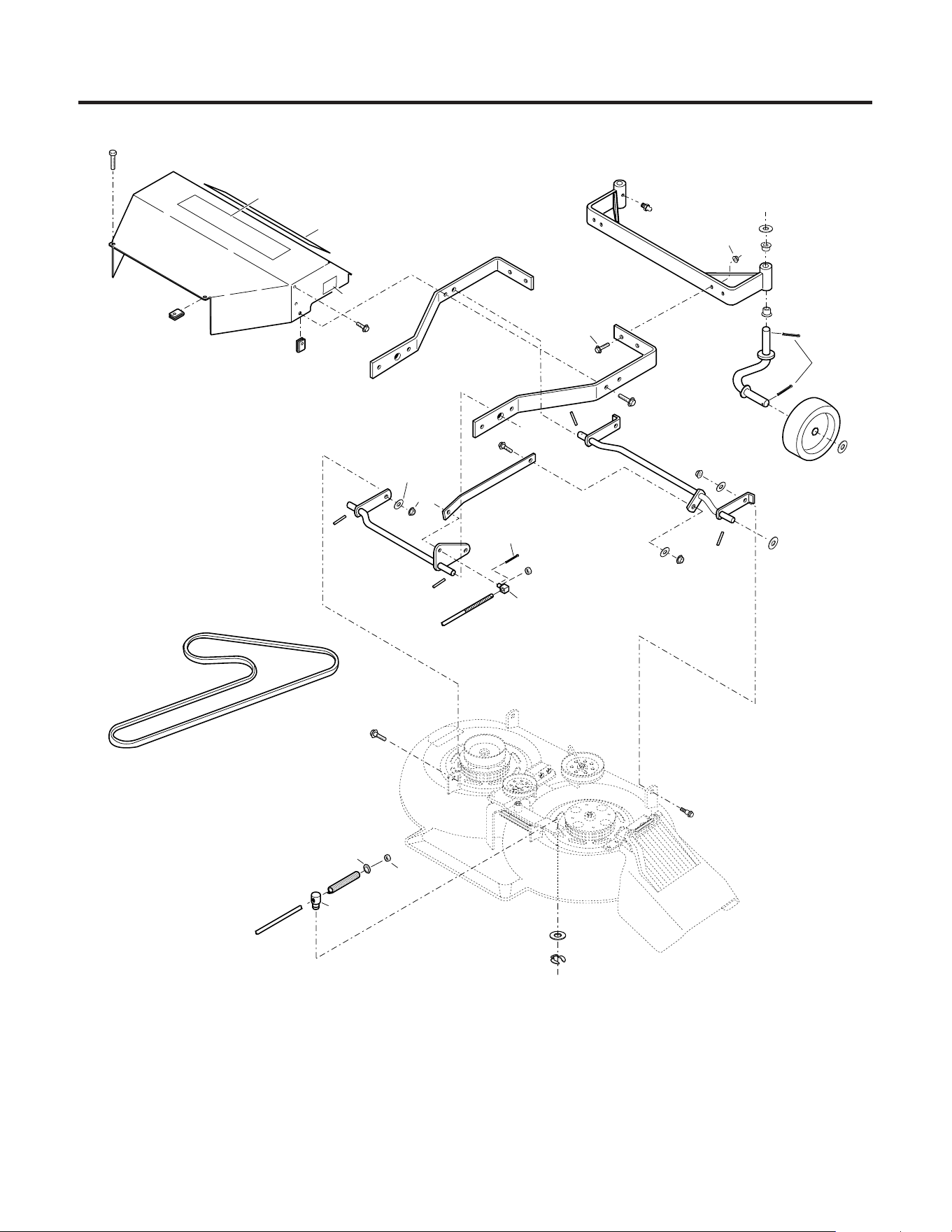
32
Wide-Cut Combination Mower
FRONT FRAME ASSEMBLY
151
149
105
103
104
316
100
158
110
95
106
108
53
31
94
47
165
58
1
101
165
11
315
307
310
317
53
312
312
311
110
28
SEE PAGES 8 AND 9
FOR MOWER DECK ASSEMBLY BREAKDOWN.
309
402 Black Spray Paint Can, 13 oz.
314
313
12
308
12
73
73
165
73
97
30
2
3
28
174
28
28
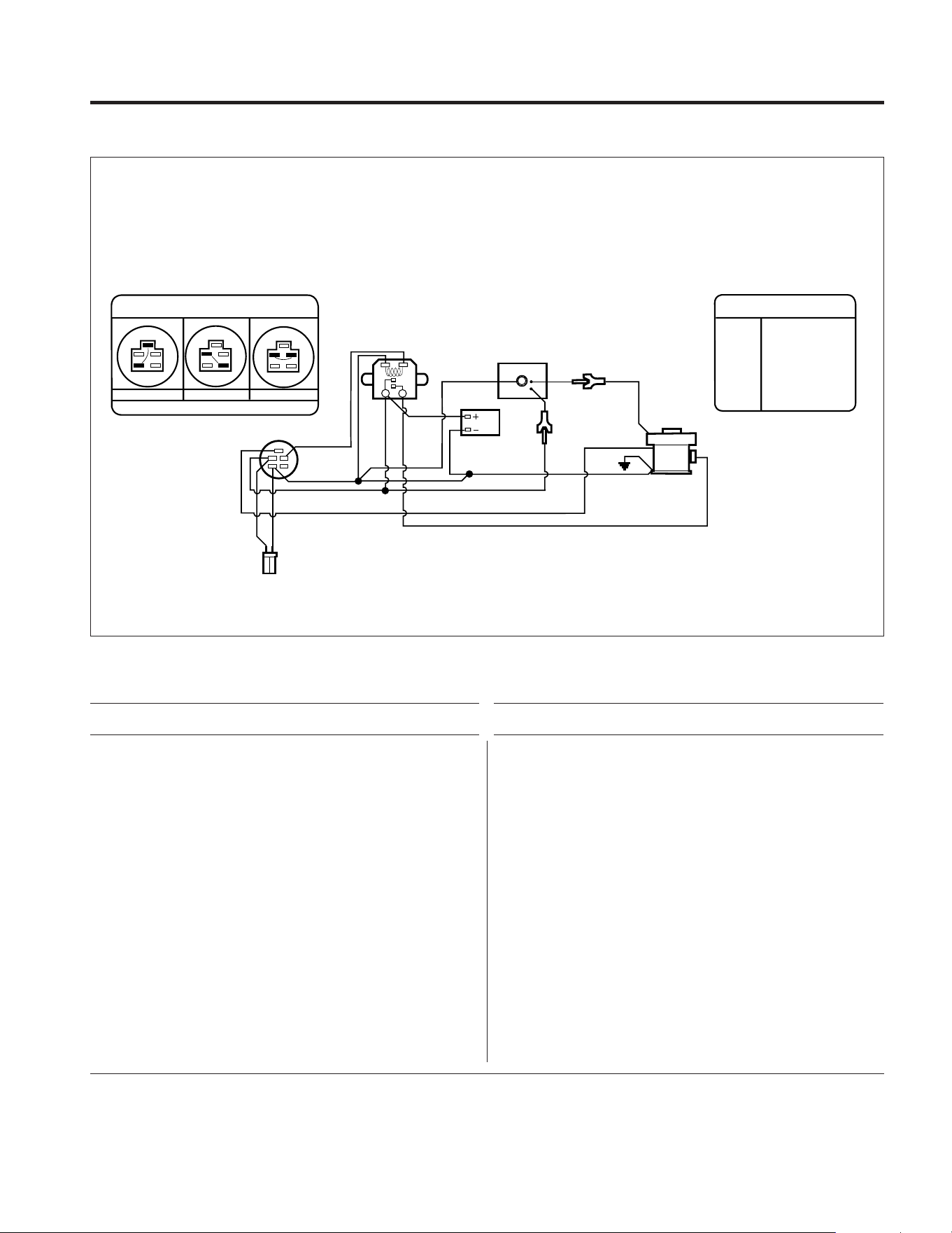
33
Models 753B, E753B
1 1916897 Pivot....................................................... 1
2 GW-20546 Washer................................................... 1
3 GW-9532 Clip Ring ................................................ 1
11 1186393 Flange Locknut, 3/8-16........................... 9
16 1185147 Cotter Pin, 3/32 x 5/8 ............................. 2
28 736-3050 Flat Washer, 3/8 ..................................... 6
30 712-3000 Locknut, 3/8-16...................................... 1
31 1769895 Lift Crank................................................ 1
47 714-0474 Cotter Pin ............................................... 1
53 1701447 Special Washer....................................... 4
58 1770247 Lower Blade Rod.................................... 1
73 1185506 Flange Locknut, 3/8-16........................... 5
94 1768231 Pivot Block ............................................. 1
95 1769521001 Leveler Bar ............................................. 1
97 777I00006 Cutting Height Decal............................... 1
100 1769344 Tap Screw, #8 x 3/8 ............................... 8
101 1769007 Compression Spring............................... 1
103 1185498 Speed Nut, 5/16–18 ............................... 2
104 1764996010 Belt Guard ............................................. 1
105 1185873 Speed Nut, 5/16–18 ............................... 2
106 1100352 Cotter Pin ............................................... 4
108 1743891 Gage Wheel ............................................ 2
110 1186329 Flange Lock Screw, 5/16 x 3/4 ............... 2
149 777D06078 Logo Decal ............................................ 1
151 777D06077 33" Combination Deck Decal .................. 1
158 1769767 V-Belt ..................................................... 1
165 1754125 Shoulder Bolt ......................................... 5
174 1770355 Toplock Nut............................................ 1
307 1769903001 Rear Lift Assembly ................................. 1
308 1185469 Roll Pin, 1/4 x 1...................................... 2
309 736-0156 Flat Washer, 5/8 ..................................... 1
310 1770248001 Front Lift Assembly ................................ 1
311 1768477001 Spindle Assembly................................... 2
312 1764140 Flange Bearing........................................ 4
313 1769743001 Gage Support ......................................... 1
314 1185976 Grease Fitting ......................................... 2
315 1185759 Drive Pin, 1/4 x 3.................................... 2
316 1769899001 Mower Support ...................................... 2
317 1186347 Whizlock Screw, 3/8-16 x 1.................... 4
402 1735222 Black Spray Paint Can, 13 Oz. ............... N/I
Ref. Part Description Qty.
Ref. Part Description Qty.
FRONT FRAME ASSEMBLY
R/W
To Charger
B
R
Gnd
Mag
Starter
BL
W/B
B
R
B
R
Y
Alt
Solenoid
Regulator
Battery
Ignition
Switch
Engine
WIRE COLOR CODE
B
BL
R
W
Y
R/W
W/B
Black
Blue
Red
White
Yellow
Red/White
White/Black
REAR VIEW
OFF
RUN
START
M
S
R
B
G
M
S
R
B
G
M
S
R
B
G
IGNITION SWITCH
ELECTRICAL DIAGRAM – MODEL E753B ONLY
N/I Item not included with unit; order separately.
(A) Model 753B
(B) Model E753B
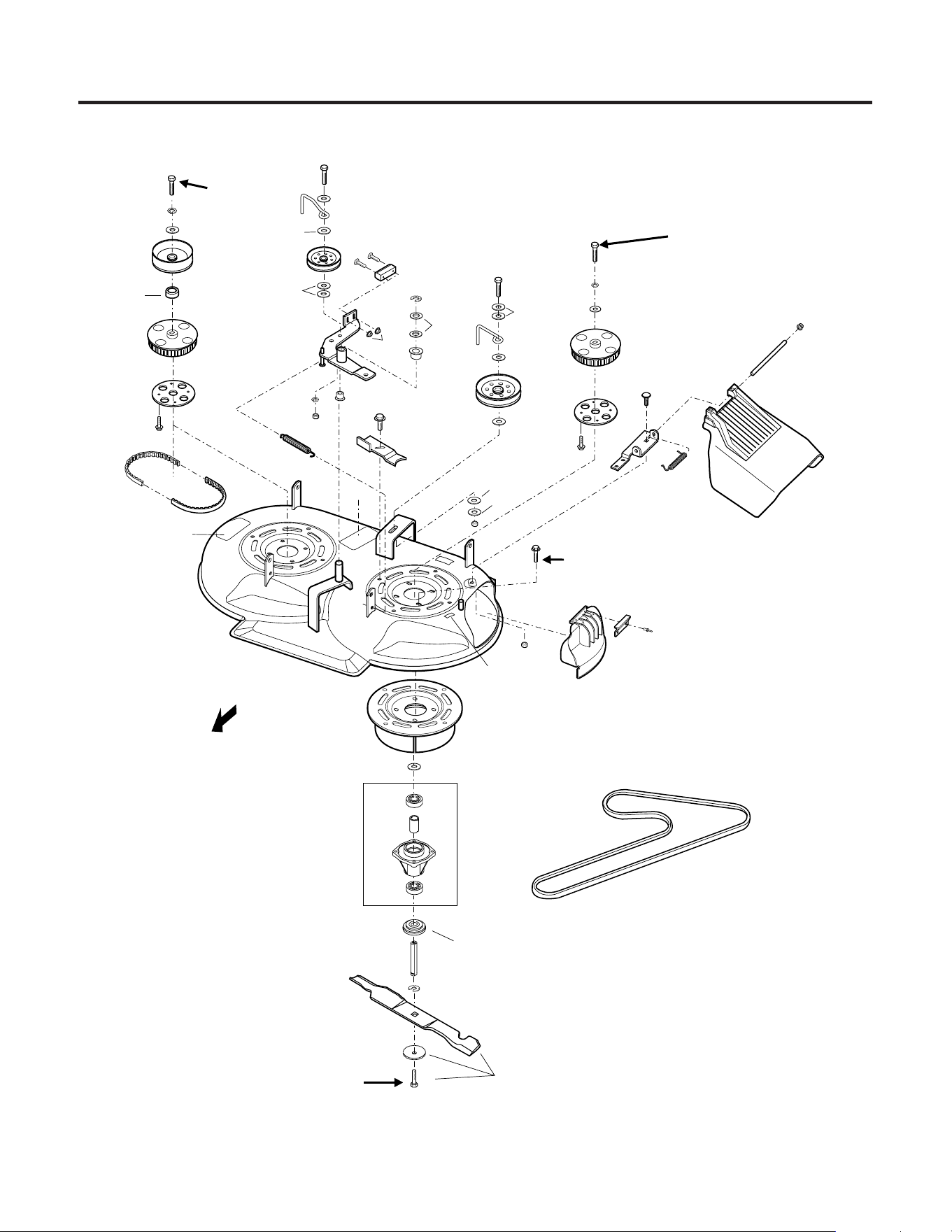
34
MOWER DECK ASSEMBLY
Wide-Cut Combination Mower
39
23
TORQUE TO
15 FT. LBS.
19
21
22
44
36
37
55
27
40
34
32
31
59
24
41
36
14
27
40
40
43
25
26
35
44
22
21
20
19
38
50
51
17
7
8
5
TORQUE TO
35 FT. LBS.
319
18
320
2
3
4
2
318
6
9
10
12
LOCTITE INTO
PLACE
TORQUE TO
35 FT. LBS.
33
LOCTITE INTO PLACE
TORQUE TO
35 FT. LBS.
158 (ALSO APPEARS ON PAGE 6-7)
13
29
15
46
42
24
40
40
40
Rear of Unit
400 LOCTITE 242, 0.02 OZ. TUBE
48
50
51
54
58
53
56
57
60
52
28
30
11
47

35
Models 753B, E753B
2 1185574 Ball Bearing ............................................ 4
3 1746869 Spacer.................................................... 2
4 1765092 Mower Spindle ....................................... 2
5 Ref. No. not used ...................................
6 1765029 Blade Spacer .......................................... 2
7 1766061 Right Spindle Shaft ............................... 1
8 1768169 Left Spindle Shaft (long) ........................ 1
9 1765196 Screw, 7/16-14 x 1................................ 2
10 1765197 Belleville Washer .................................... 2
11 1910917 Blade, 33" Mulching................................ 2
12 1185649 Retaining Ring........................................ 2
13 1771081 Flat Head Screw, #10-24 x 1-1/4........... 2
14 1771083 Brake Pad............................................... 1
15 1185985 Nylon Locknut, #10-24 .......................... 2
17 1773600 Toothed Drive Belt ................................. 1
18 777S00004 Caution Decal ........................................ 1
19 1774220 Cogged Pulley, 56T ................................ 2
20 1769362 Drive Pulley ............................................ 1
21 1736484 Flat Washer, 7/16 ................................... 2
22 736-0171 Lock Washer, 7/16 ................................. 2
23 1773523 Flange Lock Screw, 5/16-18 x 1 ............. 8
24 1764140 Flange Bushing....................................... 2
25 1701055 Flat Washer ............................................ 2
26 1762794 Idler Pulley ............................................. 1
27 1100062 Hex Head Capscrew, 3/8-16 x 2-1/2....... 2
28 1911054 Adapter Trim .......................................... 1
29 1918371 Idler Arm ................................................ 1
30 1186059 Pop Rivet ............................................... 2
31 1911021001 Belt Tension Adjustment Bracket ........... 1
32 1749911 Idler Pulley ............................................. 1
33 1766787 Special Thrust Washer ........................... 2
34 1720717 Belt Guide............................................... 1
35 1756595 Extension Spring .................................... 1
36 1186231 Nut, 3/8-16............................................. 2
37 1732499 Locknut, 5/16-18.................................... 1
38 1723996 Pulley Spacer ......................................... 1
39 777S30118 Danger Decal.......................................... 1
40 1768818 Flat Washer, 3/8 x 3/4 ............................ 7
41 736-0169 Lock Washer, 3/8 ................................... 1
42 1701447 Flat Washer ............................................ 2
43 1764135 Belt Guide............................................... 1
44 1769397 Screw, 7/16-14 x 1-1/4 ......................... 2
46 716-0101 Retaining Ring........................................ 1
47 777S00008 Warning Decal........................................ 1
48 1185715 Pyramid Washer, 3/8.............................. 1
50 1771925 Triplask Screw, 1/4-20 x 5/8 .................. 8
51 1771922001 Sprocket Plate ........................................ 2
52 1773642 Mulcher Cover, Fold-Up Style
(Incl. Ref. 28 and 30) ......................... 1
53 1727342 Cap......................................................... 2
54 1910931 Discharge Chute..................................... 1
55 1910948001 Weldment Doubler ................................. 2
56 1910951001 Bracket, Chute Hinge.............................. 1
57 1910971 Spring, Discharge Chute......................... 1
58 1910972 Pin, Discharge Chute.............................. 1
59 1740496 Screw, Thread-Forming.......................... 8
60 GW-90077 Bolt, Carriage, 3/8-18 x 3/4 .................... 1
158 1769767 V-Belt ..................................................... 1
318 1773595 Mulching Blade Kit
(Incl. Refs. 9 ,10 and 11).................... 1
319 1773587 Mower Deck Assembly
(Incl. Refs. 18, 39 & 47) (A) (B).......... 1
320 1769048 Mower Spindle Assembly
(Incl. Refs. 2, 3, 4 & 5)........................ 2
400 GW-97092 Loctite 242, 0.02 oz. Tube...................... N/I
401 1735222 Black Spray Paint Can, 13 oz. ................ N/I
Ref. Part Description Qty.
Ref. Part Description Qty.
MOWER DECK ASSEMBLY
N/I Item not included with unit; order separately.
(A) Model 753B
(B) Model E753B
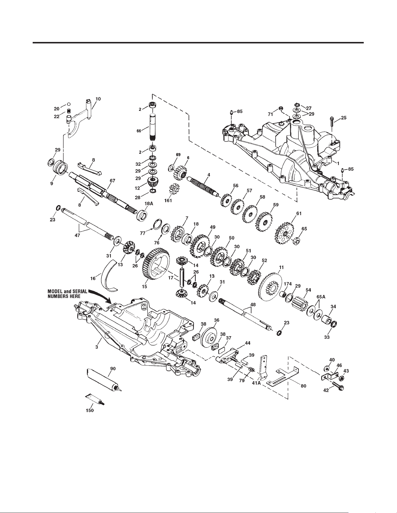
36
Peerless Transaxle

37
Model 915-027
Ref. Part Description Qty.
Ref. Part Description Qty.
ORDER ALL TRANSAXLE PARTS FROM YOUR LOCAL PEERLESS-TECUMSEH DEALER
1 772113 Transaxle Cover ............................... 1
1 772135 Transaxle Cover ............................... 1
2 780086 Needle Bearing ................................ 2
3 770110 Transaxle Case ................................ 1
4 776300 Countershaft ................................... 1
6 778281 Spur Gear (16 teeth) ........................ 1
7 778122A Spur Gear (22 teeth) ........................ 1
8 792160 Shift Key ......................................... 4
9 784373 Shift Collar ...................................... 1
10 784365 Shift Rod & Fork ............................. 1
11 778261 Bevel Gear & Bearing (Incl. 174) ..... 1
12 778262 Bevel Pinion (14 teeth)..................... 1
13 778221 Bevel Gear (16 teeth) ..................... 2
14 778068 Differential Pinion ......................... 2
15 778260 Ring Gear ........................................ 1
16 786150 Bearing Strip .................................. 1
17 786139 Drive Pin ......................................... 1
18 786147 Neutral Spacer ................................ 1
18A 786159 Neutral Spacer ................................ 1
20 792077 Ball, 5/16” dia. ................................ 1
22 792079 Spring ............................................. 1
23 788061 Seal Ring ......................................... 2
25 792073 Screw, 1/4-20 x 1-1/4” .................... 17
26 792125 Retaining Ring ................................ 4
27 792035 Retaining Ring ................................ 1
28 788040 Retaining Ring ................................ 1
29 780072 Washer ............................................ 6
30 780108 Washer ............................................ 3
31 780001 Washer ............................................ 2
32 792001 “O” Ring .......................................... 1
33 788076 “O” Ring .......................................... 1
34 780159 Bushing ........................................... 1
36 790071 Brake Disk ....................................... 1
37 790007 Brake Pad Plate ............................... 1
38 799021 Brake Pad (pkg. of 2) ...................... 2
39 786026 Dowel Pin ........................................ 2
40 792076A Washer ............................................ 1
41 790045 Brake Lever ..................................... 1
42 792073 Screw, 1/4-20 x 1-1/4” .................... 2
43 792075 Locknut, 5/16-24 ............................ 1
44 790025 Brake Pad Holder ............................ 1
46 786086 Brake Lever Bracket ........................ 1
47 774747 Axle (16-1/4” long) ......................... 1
48 774888 Axle (11” long) ................................ 1
49 778124A Spur Gear (30 teeth) ........................ 1
50 778123A Spur Gear (25 teeth) ...................... 1
51 778122A Spur Gear (22 teeth) ....................... 1
52 778273 Spur Gear (19 teeth) ....................... 1
54 778263 Spur Gear (11 teeth) ....................... 1
56 778126A Spur Gear (20 teeth) ....................... 1
57 778127A Spur Gear (25 teeth) ...................... 1
58 778128A Spur Gear (28 teeth) ....................... 1
59 778129A Spur Gear (30 teeth) ....................... 1
61 778265 Spur Gear (34 teeth) ....................... 1
65 780162 Washer ............................................ 1
65A 780160 Washer ............................................ 2
66 776299 Input Shaft ...................................... 1
67 776352 Shifter & Brake Shaft ...................... 1
69 780161 Washer ............................................ 1
71 788069 Square Cut Ring .............................. 1
76 780090 Washer ............................................ 1
77 788078A Inverted Retaining Ring (pkg. of 2) . 1
79 792144 Spring ............................................. 1
80 790063A Brake Bracket .................................. 1
85 792137 Lubrication Fitting ........................... 2
90 788067B Grease
(32 oz. bottle Bentonite grease) .. 1
150 510334 Gasket Eliminator (Loctite #515) ..... 1
161 776302 Reverse Idler ................................... 1
174 780085 Needle Bearing ............................... 1
TRANSAXLE ASSEMBLY

38
MANUFACTURER’S LIMITED WARRANTY FOR:
The limited warranty set forth below is given by Troy-Bilt LLC
with respect to new merchandise purchased and used in the
United States, its possessions and territories.
Troy-Bilt LLC warrants this product against defects for a period
of two (2) years commencing on the date of original purchase
and will, at its option, repair or replace, free of charge, any part
found to be defective in materials or workmanship. This limited
warranty shall only apply if this product has been operated and
maintained in accordance with the Operator’s Manual furnished
with the product, and has not been subject to misuse, abuse,
commercial use, neglect, accident, improper maintenance, alter-
ation, vandalism, theft, fire, water, or damage because of other
peril or natural disaster. Damage resulting from the installation
or use of any accessory or attachment not approved by Troy-Bilt
LLC for use with the product(s) covered by this manual will void
your warranty as to any resulting damage.
Normal wear parts or components thereof are subject to sepa-
rate terms as follows: All normal wear parts or component fail-
ures will be covered on the product for a period of 90 days re-
gardless of cause. After 90 days, but within the two year period,
normal wear part failures will be covered ONLY IF caused by de-
fects in materials or workmanship of OTHER component parts.
Normal wear parts and components include, but are not limited
to: batteries, belts, blades, blade adapters, grass bags, rider
deck wheels, seats, snow thrower skid shoes, shave plates,
auger spiral rubber, tires.
HOW TO OBTAIN SERVICE: Warranty service is available,
WITH PROOF OF PURCHASE, through your local authorized
service dealer. To locate the dealer in your area, check your
Yellow Pages, or contact Troy-Bilt LLC at P.O. Box 361131,
Cleveland, Ohio 44136-0019, 1-866-840-6483, or log on to our
Web site at www.troybilt.com.
This limited warranty does not provide coverage in the following
cases:
a. The engine or component parts thereof. These items
carry a separate manufacturer’s warranty. Refer to the
applicable manufacturer’s warranty for terms and cond
tions.
b. Log splitter pumps, valves, and cylinders have a separate
one year warranty.
c. Routine maintenance items such as lubricants, filters,
blade sharpening, tune-ups, brake adjustments, clutch
adjustments, deck adjustments, and normal deterioration of
the exterior finish due to use or exposure.
d. Troy-Bilt LLC does not extend any warranty for products
sold or exported outside of the United States, its pos-
sessions and territories, except those sold through Troy-
Bilt LLC’s authorized channels of export distribution.
e. Parts that are not genuine Troy-Bilt parts are not covered by
this warranty.
f. Service completed by someone other than an authorized
service dealer is not covered by this warranty.
g. Transportation charges and service calls are not covered.
No implied warranty, including any implied warranty of mer-
chantability of fitness for a particular purpose, applies after
the applicable period of express written warranty above as
to the parts as identified. No other express warranty,
whether written or oral, except as mentioned above, given
by any person or entity, including a dealer or retailer, with
respect to any product, shall bind Troy-Bilt LLC. During the
period of the warranty, the exclusive remedy is repair or re-
placement of the product as set forth above.
The provisions as set forth in this warranty provide the sole
and exclusive remedy arising from the sale. Troy-Bilt LLC
shall not be liable for incidental or consequential loss or
damage including, without limitation, expenses incurred for
substitute or replacement lawn care services or for rental
expenses to temporarily replace a warranted product.
Some states do not allow the exclusion or limitation of incidental
or consequential damages, or limitations on how long an implied
warranty lasts, so the above exclusions or limitations may not
apply to you.
In no event shall recovery of any kind be greater than the
amount of the purchase price of the product sold.
Alteration of
the safety features of the product shall void this warranty.
You assume the risk and liability for loss, damage, or injury to
you and your property and/or to others and their property arising
out of the misuse or inability to use the product.
This limited warranty shall not extend to anyone other than the
original purchaser or to the person for whom it was purchased
as a gift.
HOW STATE LAW RELATES TO THIS WARRANTY: This
limited warranty gives you specific legal rights, and you
may also have other rights which vary from state to state.
TROY-BILT LLC, P.O. BOX 361131, CLEVELAND, OHIO 44136-0019, 1-866-840-6483