Loading ...
Loading ...
Loading ...

14 SECTION 3 — CONTROLS & OPERATION
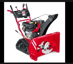
Engine Controls
Refer to your Engine Operator’s Manual for
location and description of engine controls
pertaining to your engine. Yours may differ
slightly from the one pictured in Figure 3-2.
Choke Lever
Electric Starter
Outlet
Electric
Starter
Button
Throttle
Control
Safety Key
Primer
Figure 3-2
Choke Lever
Activating the choke control closes the choke
plate on carburetor and aids in starting engine.
The choke lever slides between the RUN and
CHOKE positions.
Primer
Pressing the primer, making sure to cover the
vent hole when pushing, forces fuel directly
into the engine’s carburetor to aid in cold-
weather starting.
Safety Key
The safety key is a safety device. It must be
fully inserted in order for the engine to start.
Remove the safety key when the snow thrower
is not in use.
Electric Starter Outlet
Requires the use of a grounded, three-prong
outdoor extension cord and a 120V power
source/wall outlet.
Electric Starter Button
Pressing the electric starter button engages
the engine’s electric starter when plugged into
a 120V power source.
Throttle Control
The throttle control regulates the speed of
the engine and will shut OFF the engine when
moved into the STOP position.
Shift Lever
The shift lever is located on the handle panel
and is used to determine ground speed and
direction of travel.
Forward
There are six forward (F) speeds. Position
one (1) is the slowest and position six (6) is the
fastest.
Reverse
There are two reverse (R) speeds. Position one
(1) is the slower and position two (2) is the
faster.
Chute Assembly
Snow drawn into the auger housing is
discharged out the chute assembly.
Skid Shoes
Position skid shoes based on surface
conditions. Adjust upward for hard-packed
snow. Adjust downward when operating on
gravel or crushed rock surfaces. See Skid Shoe
Adjustment section on page 12.
Augers
When engaged, the augers rotate and draw
snow into the auger housing.
Headlight
The headlight is located on top of the handle
panel and is automatically turned ON when the
engine is started.
LED Light Bar (If Equipped)
The LED headlight is located on top of the
auger housing and is automatically turned ON
when the engine is started.
Heated Grips
CAUTION: It is recommended
that you wear gloves when using
the heated grip. If the heated
grips become too hot, turn it
OFF.
To activate the heated grips, move switch
found on rear of dash panel into the ON
position. See Figure 3-3. To turn OFF heated
grips, move switch found on rear of dash panel
to OFF position.
Switch
ON
Switch
OFF
Figure 3-3
Auger Control Lever
The auger control lever is located on the left
handle. Squeeze the control lever against the
handle to engage the augers and start snow
throwing action. Release to stop.
See Figure 3-4.
Figure 3-4
Drive Control Lever / Auger Clutch
Lock
The drive control lever is located on the right
handle. Squeeze the control lever against the
handle to engage the wheel drive. Release to
stop. See Figure 3-5.
Figure 3-5
The drive control lever also locks the auger
control lever so that you can operate the chute
directional control without interrupting the
snow throwing process. If the auger control
lever is engaged simultaneously with the drive
control lever, the operator can release the
auger control lever (on the left handle) and
the augers will remain engaged. Release both
control levers to stop augers and wheel drive.
NOTE: Always release drive control lever
before changing speeds. Failure to do so will
result in increased wear on your machine’s
drive system.
Steering Trigger Controls
The left and right wheel steering trigger
controls are located on the underside of the
handles. Refer to Figure 3-6.
Figure 3-6
Loading ...
Loading ...
Loading ...