Part of ASSA ABLOYP/N YRD400-KF-0022 Rev ATrusted every day
1
Failure to follow these instructions could result in damage to the product, voiding the factory warranty and could lead to failure of the product to provide access.
Yale Assure Lock® 2 Key-Free Deadbolt Installation Guide
(Keypad YRD430 or Touchscreen YRD450)
Notice: Before installing your lock, be sure to follow the steps on the yellow Quick Start Guide.
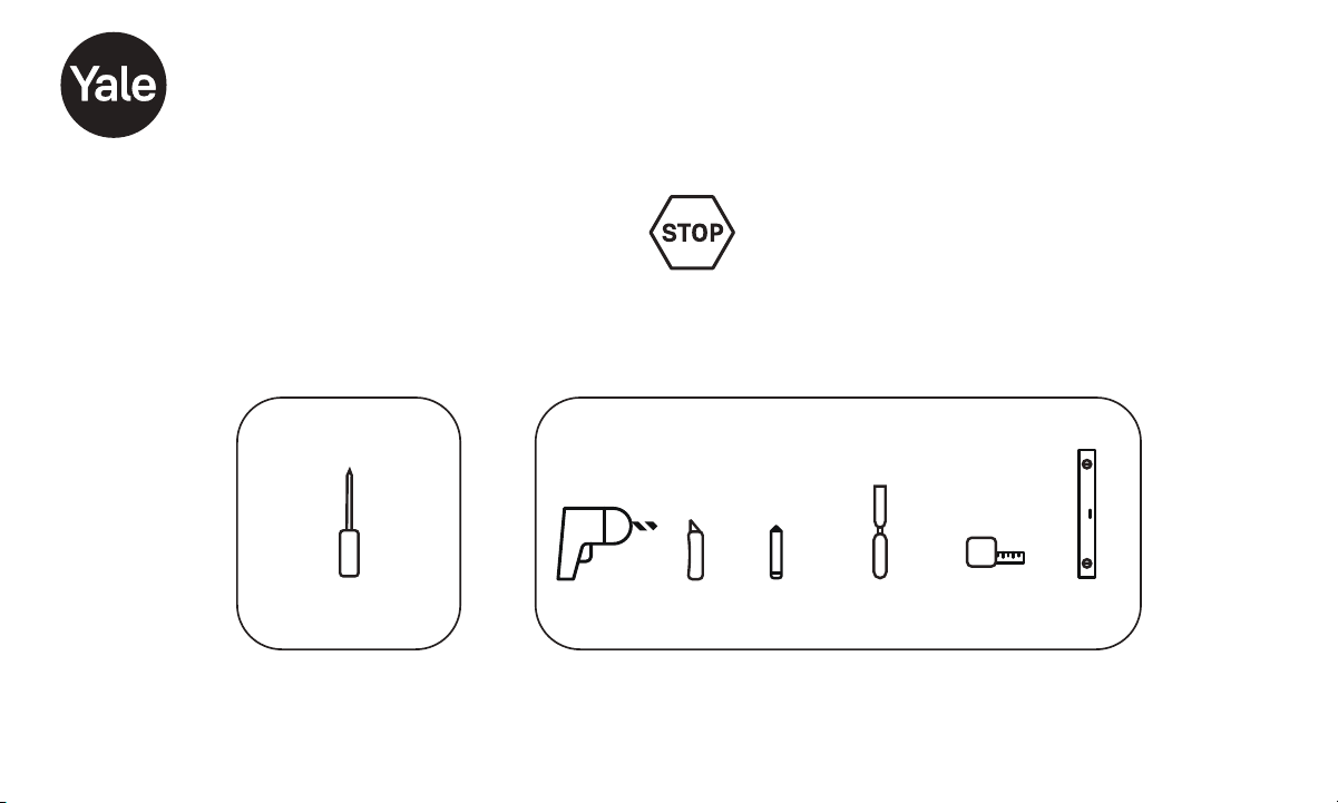
Tools Needed
Standard Phillips
Head Screwdriver
Tools Needed To Adjust An Existing Door
or Prep a New Door
Drill Utility
Knife
Wood
Mortise Chisel
Tape
Measure
Level
Pencil

Part of ASSA ABLOYP/N YRD400-KF-0022 Rev ATrusted every day
2
In The Box
AA
AA
AA
AA
Yale Smart Module
(with select models)
Exterior Keypad
Interior Lock
Mounting Plate
Batteries
Screws and
Plastic Clips
(pre-installed)
Battery Cover
Guide
Hardware Components
x4
x2
Note: You must use the provided screws from the
hardware pack when installing this lock.
Adjustable Deadbolt
Latch (AYRDB DRIVE
Adjustable Drive-In Deadbolt
Latch available for purchase)
Reset Pin
Strike
Plate
x2
Screw Set D
Silver for
2 to 2-1/4"
Door Thickness
x2
Screw Set C
Black for
Standard 1-3/4"
Door Thickness
x2
Screw Set B
Blue for
1-3/8"
Door Thickness
x2
Optional
Security
Strike Plate
Screws
x4
Strike Plate
and Deadbolt
Screws
x20mm
DoorSense
DoorSense
Screws
Cover
Housing
Mounting Tape
Flush Mount Cap

Part of ASSA ABLOYP/N YRD400-KF-0022 Rev ATrusted every day
3
1
Remove Existing Deadbolt
Keep your old deadbolt until your new lock has been successfully installed.
Door
Frame

Part of ASSA ABLOYP/N YRD400-KF-0022 Rev ATrusted every day
4
Check Door:
Tear off the Door Checker page of this guide and follow
instructions to verify your door measurements and make any
needed adjustments.
Note: There are some cases where existing holes cannot be
adjusted to be compatible.
New Door:
Tear off the Template page of this guide and use either 2-1/8" or
1-1/2" template to prepare a new door that has no holes or to
adjust existing holes to be compatible.
Check Door Measurements and Adjust If Needed
2
Check Your Door Guide
1/4
1/8 3/8 5/8
3/4
7/8
0123
1/4
1/8 3/8 5/8
3/4
7/8
1/4
1/8 3/8 5/8
3/4
7/8
1/2 1/2 1/2
I
B
Blue
C
Black
D
Silver
EF
45
1/2 1/2
1/4 3/4 1/4 1/4
1/2
1/8 3/8 5/8 7/8 1/8 3/8 5/8 1/8 3/8
A
A. 2" Minimum clearance between top of
existing lever/knob rose (trim) and center
of deadbolt hole.
2" tolerance for optimal Door Sense
location.
B. 1-3/8" Door Thickness se blue Screw; u
Set B (shortest set).
C. 1-3/8" - 1-3/4" DoorThickness; use black
Screw Set C.
D. 1-3/4" - 2-1/4" Door Thickness; use silver
Screw Set D (longest set).
E; u. 2-3/8" Backset se Out of Box latch
setting.
F. 2-3/4" Backset; adjust latch setting.
Instructions on how to adjust the latch
are included in manual.
G. 1-1/2" Face Bore Diameter. Instructions
on how to remove the black adapter from
the lock are included in manual.
1-1/2"tolerance from inside door frame
edgefor optimal Door Sense location.
H. 2-1/8" Face Bore Diameter.
I. Ed ge Bore Diameter and Depth.
Cross Bore Diameter.
H
3/4
7/8
67
1/2
1/4 3/4
1/8 3/8 5/8 7/8
3/4
7/85/8
CAUTION:
If printed from electronic file,
Measure ruler to check scale.
set print scale to 1:1
G
To ensure a successful installation, measure each aspect of your door and frame as shown in panels (left side of sheet) using
the ruler above. Make sure all of your dimensions are a . See letter definitions below for guidance.
FO LD OV ER DO OR E DGE
Centerline
Center
of 1" (25mm)
hole through
edge of door
For 1-3/8"
35mm()
Thick Door
2-3/8" 60mm Backset()
2-3/4"70mm Backset()
For 1-3/"4
mm(44.5 )
Thick Door
Center
of 2-1/8" (54mm)
hole through face
of door
Center
of 2-1/8" (54mm)
hole through face
of door
Center
of 1" (25mm)
hole through
edge of door
Door
CAUTION:
If printed from electronic file,
Measurea dimension
to check scale.
set print scale to 1:1

Part of ASSA ABLOYP/N YRD400-KF-0022 Rev ATrusted every day
5
Verify Measurements with the Check Your Door Guide
Equals I
Less than I
(Adjust diameter
to 1")
Greater than I
(Your door is not
a match for a
Yale smart lock)
X
1"
(25mm)
Dia.
1" (25mm) Dia.
1" (25mm) Deep
Frame
Equals I
Less than I
(Adjust diameter
and depth to 1")
Greater than I
(Your door is not
a match for a
Yale smart lock)
X
X
2- /8" ( mm)154
OR
1-1/2" (38mm)
Equals G or H
Less than G
(Adjust diameter
to G or H)
Greater than H
(Your door is not
a match for a
Yale smart lock)
X
X
MeasureStrike Pocket
Diameter and Depth
Measure Cross Bore
Supérieur à A
Moins que A
(votre porte n’est
pas compatible avec
une serrure
intelligente Yale)
X
Mesure du dégagement
B, C ou D
X
Mesurer l’épaisseur de la porte
X
2- /8" ( mm)360
or
2-3/4" (70mm)
Backset
Equals E or F
Less than E or F
(Your door is not
a match for aYale
smart lock)
Greater than E or F
(Your door is not
a match for aYale
smart lock)
X
X
Measure Backset
Measure Face Bore
Recommended Location
of DoorSense
X
A: Within
2" of Yale
logo on
battery
cover.
G: Within
1-1/2" from
inside
frame
edge.
"2
51(mm)
"1-1/2
38(mm)
Moins que B
(votre porte n’est
pas compatible
avec une serrure
intelligente Yale)
Supérieur à D
(votre porte n’est
pas compatible
avec une serrure
intelligente Yale)
Cut Here

Part of ASSA ABLOYP/N YRD400-KF-0022 Rev ATrusted every day
6
Check Your Door Guide
1/4
1/8 3/8 5/8
3/4
7/8
0123
1/4
1/8 3/8 5/8
3/4
7/8
1/4
1/8 3/8 5/8
3/4
7/8
1/21/2 1/2
I
B
Blue
C
Black
D
Silver
EF
45
1/21/2
1/4 3/4 1/41/4
1/2
1/8 3/8 5/8 7/8 1/8 3/8 5/8 1/8 3/8
A
A. 2" Minimum clearance between top of
existing lever/knob rose (trim) and center
of deadbolt hole.
2" tolerance for optimal Door Sense
location.
B. 1-3/8" Door Thickness se blue Screw; u
Set B (shortest set).
C. 1-3/8" - 1-3/4" Door Thickness; use black
Screw Set C.
D. 1-3/4" - 2-1/4" Door Thickness; use silver
Screw Set D (longest set).
E; u. 2-3/8" Backset se Out of Box latch
setting.
F. 2-3/4" Backset; adjust latch setting.
Instructions on how to adjust the latch
are included in manual.
G. 1-1/2" Face Bore Diameter. Instructions
on how to remove the black adapter from
the lock are included in manual.
1-1/2" tolerance from inside door frame
edgefor optimal DoorSense location.
H. 2-1/8" Face Bore Diameter.
I. Edge Bore Diameter and Depth.
Cross Bore Diameter.
H
3/4
7/8
67
1/2
1/4 3/4
1/8 3/8 5/8 7/8
3/4
7/85/8
CAUTION:
If printed from electronic file,
Measure ruler to check scale.
set print scale to 1:1.
G
To ensure a successful installation, measure each aspect of your door and frame, as shown in panels (left side of sheet) using
the ruler above. Make sure all of your dimensions are a . See letter definitions below for guidance.
Cut Here

Part of ASSA ABLOYP/N YRD400-KF-0022 Rev ATrusted every day
7
Template to Mark a Door for 2-1/8" Face Bore
FOLD OVER DOOR
EDGE
Centerline
Center
of 1" (25mm)
hole through
edge of door
For 1-3/8"
35mm()
Thick Door
2-3/8" 60mm Backset()
2-3/4" 70mm Backset()
For 1-3/ "4
mm(44.5)
Thick Door
Center
of 2-1/8" (54mm)
hole through face
of door
Center
of 2-1/8" (54mm)
hole through face
of door
Center
of 1" (25mm)
hole through
edge of door
Door
CAUTION:
If printed from electronic file,
Measure a dimension
to check scale.
set print scale to 1:1.
Cut Here

Part of ASSA ABLOYP/N YRD400-KF-0022 Rev ATrusted every day
8
Template to Mark a Door for 1-1/2" Face Bore
FOLD OVER DOOR
EDGE
2-3/4" 70mm Backset()
For 1-3/ "4
mm(44.5)
Thick Door
CAUTION:
If printed from electronic file,
Measurea dimension
to check scale.
set print scale to 1:1.
Centerline
For 1-3/8"
35mm()
Thick Door
2-3/8" 60mm Backset()
Center
of -1/"12
( mm)38
hole through
face of door
Center
of -1/2"1
( mm)38
hole through
face of door
Center
of 1" (25mm)
hole through
edge of door
Center
of 1" (25mm)
hole through
edge of door
Door
Cut Here

Part of ASSA ABLOYP/N YRD400-KF-0022 Rev ATrusted every day
9
Install Deadbolt Latch and Strike Plate
3
*Correct deadbolt latch length is based on backset. Choose 2-3/8" or 2-3/4".
Door Checker measurements E and F can help you verify your backset measurement.
2-3/8"Backset, Out of Box
2-3/4" Backset, optional
*Backset
To Adjust:
Twist neck while holding body stable.
If the deadbolt latch is extended,
use your fingers or a small
flathead screwdriver to rotate slot
until deadbolt latch is retracted.
Security screws can be
used here, in place of the
small strike plate screws.
Deadbolt latch must be
in unlocked position. UP
arrow must face upwards.
Fr
ame
Door
Align
strike
with
deadbolt
latch
2-
3
/
8
2-
3
/
8
2-
3
/
4
x2
For Deadbolt
Latch
(Actual Size)
For Strike Plate
(Actual Size)
x2

Part of ASSA ABLOYP/N YRD400-KF-0022 Rev ATrusted every day
10
Verifying Bore Face Measurement for Exterior Keypad
4
Install the lock with the door open.
Do not close until all steps are completed.
Measurement G on the Door Checker will help
verify your bore face measurement.
If hole is less than 2-1/8", remove adapter by
unscrewing the two screws on either side, using a
Phillips #2 screwdriver.
Inside of Door Outside of Door
2 screws
installed
here, one on
each side
Adapter
Screws
Top of Adapter
Once confirming your bore face measurement is correct, you are ready
to install the Mounting Plate and Keypad.
Feed keypad wire under
deadbolt latch.
Part of ASSA ABLOYP/N YRD400-KF-0022 Rev ATrusted every day
11
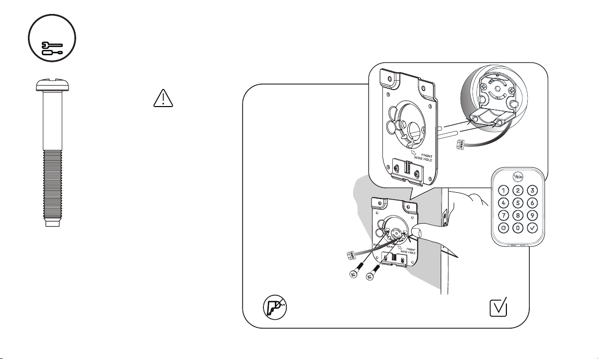
Install Mounting Plate and Exterior Keypad
5
IMPORTANT:
There are 3 bolt sets with your
lock. Choose the bolt length for
your door thickness.
Measurement B, C, or D on
the Door Checker will help you
identify which bolts to use.
1-3/8" Door Thickness;
use blue Screw Set B
(shortest set)
1-3/8" - 1-3/4" Door Thickness;
use black Screw Set C
1-3/4" - 2-1/4" Door Thickness;
use silver Screw Set D
(longest set)
Position keypad on the
outside of door, feeding wire
as shown.
Hold keypad to front of door,
while positioning plate to
inside of door.
Guide wire through the
‘front wire hole’ in plate.
Insert 2 bolts through
the plate.
Hand tighten bolts with a
Phillips screwdriver,
ensuring plate and
keypad are straight.
Inside and Outside of Door
Use Phillips screwdriver when attaching mounting
plate bolts to keypad.
x2
Bolt Set C, Black
foraStandard
1-3/4" Door
Thickness
Keypad
Wire
Front Wire
Hole

Part of ASSA ABLOYP/N YRD400-KF-0022 Rev ATrusted every day
12
Make sure wire is
attached securely.
Ridges face outward
Attach Wire to Inside of Interior Lock
6

Part of ASSA ABLOYP/N YRD400-KF-0022 Rev ATrusted every day
13
Install Interior Lock
7
Screws are pre-installed. Tighten
when lock is seated on plate.
When fully tightened, lock should
be flush to door.
Tailpiece must
be vertical.
Insert tailpiece
through deadbolt
latch slot.
Push the lock
towards the door,
adjusting the
position until the
plate spring latch
‘clicks’ into place
and holds the
bottom of the lock.
Hook
Spring
Latch
Tailpiece
Thumbturn
Lock
Tailpiece
Part of ASSA ABLOYP/N YRD400-KF-0022 Rev ATrusted every day
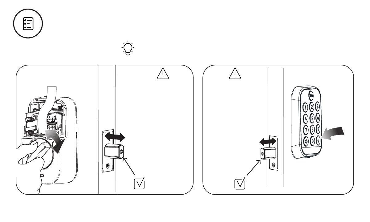
14
Test Thumbturn and Key
Smooth deadbolt latch operation will enhance your battery life.
If deadbolt latch
does not lock or
unlock when turning
thumbturn:
Ensure tailpiece is
inserted through
deadbolt latch slot.
Step 7
If deadbolt latch
does not lock or
unlock when using
the keypad or lock
door button:
Ensure deadbolt
latch is centered
in face bore hole.
Step 3
Ensure tailpiece is
inserted through
deadbolt latch slot.
Step 7

Part of ASSA ABLOYP/N YRD400-KF-0022 Rev ATrusted every day
15
Install Yale Smart Module
Included with select models
S
Select
Models
Batteries must not be installed
when inserting or removing
Yale Smart Module.

Part of ASSA ABLOYP/N YRD400-KF-0022 Rev ATrusted every day
16
Install Batteries and Replace Cover
8
Congratulations, you’ve installed the Yale Assure Lock® 2 Keyed Deadbolt!
1st
2nd
Place ribbon behind
batteries for easy
battery removal.
Deadbolt latch must
be unlocked before
installing batteries.
Pink Light and Audio Sounds
Successful Power up
The numbers will begin to light up in a
clockwise motion. Once this happens, the
lock is in pairing mode and can be set up
using the Yale Access App.
Try to connect your lock quickly as this mode
will turn off after 5 minutes. After 5 minutes,
simply touch the Yale logo to re-start the
connection to the app.

Part of ASSA ABLOYP/N YRD400-KF-0022 Rev ATrusted every day
17
Surface Mount Installation
1.5"
2"
Door Frame
9
Installing DoorSense®
Installation options:
1. Surface Mount: Only requires only the use of a screwdriver.
2. Flush Mount: Provides a cleaner and less visible look with more
robust performance, but does require drilling a ⅝" hole into your
door frame.
What’s in the box?
DoorSense
Flush Mount
Cap
Mounting Tape Housing Cover
Screws
What you’ll need
Phillips Screwdriver
Step 1. Determine mounting location
For optimal performance, DoorSense should be mounted
within 1.5" from the edge of your door frame, and align with
your lock’s Smart Module (if you are installing one).
Ensure it is in the proper position with its center aligned
with the Yale logo.

Part of ASSA ABLOYP/N YRD400-KF-0022 Rev ATrusted every day
18
9
Installing DoorSense®
Step 2. Attach mounting tape
A. Remove one side of the adhesive.
B. Attach tape to the
back of the DoorSense,
ensuring it is aligned with
the edges of the device
and screw holes.
C. Remove the remaining
piece of adhesive.
Door
Frame
Step 3. Place on door
frame
Press the adhesive side
to the frame.

Part of ASSA ABLOYP/N YRD400-KF-0022 Rev ATrusted every day
19
Step 4. Screw into frame
Hand tighten to the frame
using the included screws.
You may wish to complete
this step after your lock is set
up and calibrated to ensure
you are able to retrieve
accurate door state readings
before modifying your door
frame.
Notes: Once the lock has been set up, navigate to the
Lock Settings and select Calibrate Lock.
Follow the instructions in the app.
Open and close the door to validate the door state is
accurate. If it is not accurate or the calibration was
unsuccessful, relocate the DoorSense closer to the smart
lock and repeat the calibration process until you get
accurate results.
If you elected to not insert the screws into the door frame,
go back and secure them into your door frame or wall.
Place the cover over the housing.
If you notice that your readings are not accurate over time,
perform another Calibration.
9
Step 5. Attach the cover
Press the cover onto the
DoorSense unit.
Installing DoorSense®

Part of ASSA ABLOYP/N YRD400-KF-0022 Rev ATrusted every day
20
9
Installing DoorSense®
Flush Mount Installation
What you’ll need
• Flush Mount Cap (shown in illustration on page 16.)
• 5/8" drill blade bit • Electric drill
Step 1. Remove magnet
from the housing
Use a small blunt object to
push the magnet carrier out
of the housing.
This may require some force.
Magnet
Magnet
Carrier
PUSH
B. Press the cap onto
the notched side of
the magnet carrier.
The two shapes
should interlock.
Step 2. Assemble
magnet to cap
A. Expose the adhesive
by removing the blue
backing.
Door
Frame
Door
1.5"
Strike
Plate
DoorSense
5/8" Hole
1.5"
DoorSense is mounted 1.5" at most from the top edge of the
strike plate and centered on the door frame.
Step 3. Determine mounting location
Clips
Notches
Blue
Backing
Adhesive

Part of ASSA ABLOYP/N YRD400-KF-0022 Rev ATrusted every day
21
9
Step 4. Tape drill bit
It may be helpful to
attach tape to your
drill bit to mark the
proper depth of
hole to drill.
Although DoorSense
requires a 1/2"
deep hole, it may
be helpful to use
the assembled
DoorSense Flush
Mount as a guide.
Step 5. Drill hole
Drill the hole in the proper location on your door frame.
5/8
Tape set at 1/2"
Depth Mark
Step 7. Calibrate your Lock
Follow the instructions in the app until you have successfully
calibrated your lock and DoorSense.
Installing DoorSense®
Door
Frame
Step 6. Insert
DoorSense into
the hole
If it is too snug to push
in by hand, protect
the frame with a piece
of scrap wood and
use light blows with a
hammer or mallet.
DoorSense
Flush Mount
Door
Frame

Part of ASSA ABLOYP/N YRD400-KF-0022 Rev ATrusted every day
22
Using Your Lock
To Unlock the Door
1. Press the Yale logo on the
exterior keypad.
2. Enter the entry code.
3. Press the .
Interior Lock
Battery
Cover
Passage
Button
Indicator
Light
Thumbturn
Exterior Keypad
Warnings
Lock door
Wake or
One Touch
Locking
Yale Logo
Checkmark
Button

Part of ASSA ABLOYP/N YRD400-KF-0022 Rev ATrusted every day
23
Features
Feature
Description
DoorSense
Entry Codes
Auto-Lock
Auto-Unlock
Passage Mode
• DoorSense tells you if your door is closed or open.
Note: You can only ask a Voice Assistant if the door is locked or unlocked.
• Entry Codes are used to unlock your door.
• Create entry codes from the “Guest List” screen in our app.
• You can set the entry code to work permanently, recurring, or on a temporary schedule.
• An unlimited number of entry codes can be created or deleted at any time.
• Auto-Lock automatically locks your door for you.
• It can be set to lock on a timer, as short as 30 seconds, or as long as 30 minutes.
• When using the Auto-Lock feature with the DoorSense, your door will not lock until it is in the closed position.
• Auto-Lock can be set up in the lock settings of the app.
• Auto-Unlock knows when you arrive and unlocks the door as you approach.
• Auto-Unlock can be set up in the lock settings of the app.
• Use passage mode when you want to disable Auto-Lock for an extended period of time.
Simply press the button on the inside of the lock to turn it on.
• To turn passage mode off, simply lock your door.
Integrations
• Yale Access products work in harmony with some of your favorite smart home brands to make
life more simple and secure.
• Integrations can be set up in the Yale Access App from the “Works With” screen.

Part of ASSA ABLOYP/N YRD400-KF-0022 Rev ATrusted every day
24
Setting Definitions
Setting
Default
Definition
Codes
Programming Code
Automatically
created by theYale
Access App
This code is used to access programming features: Handing, Smart Module integration, and
Diagnostics. This code cannot be used to unlock the door. Find your programming code in the
Yale Access App, enter this code on the keypad and press the gear symbol.
Entry Codes
Entry codes can be created,from the Yale Access App, for users to allow them to lock/unlock
the door from the lock keypad.
Security Settings
Hide Entry Codes Off If turned on, all entry codes within the app will be hidden from view.
VerifiedAccessOff If turned on, biometric/passcode authentication is required from the app to operate the lock.
Notifications
Smart Alerts OffCreate alerts you wish to receive from the app.
Automation
Auto-Lock
Off
Door will automatically lock, either when door is closed (with DoorSense), or based on a timer.
Auto-Unlock Door will automatically unlock when you arrive home.
DoorSense
Must be installed Allows you to know when your door is opened or closed.
Off

Part of ASSA ABLOYP/N YRD400-KF-0022 Rev ATrusted every day
25
Setting Definitions
Setting
Default
Definition
Advanced Device Settings
Volume
Operating Mode:
Normal
Operating Mode:
Vacation
Inside Indicator
Light
One Touch Locking
Passage Button
On
On
Off
Off
On
Off
This feature can be changed in theYaleAccess App.You can turn the lock volume on or off.
When the lock is in normal operating mode all entry codes will work and the lock can be
unlocked/locked from the app and voice assistants.
This feature can be enabled in theYaleAccess App. When enabled all entry code access will be
restricted. Users can still lock and unlock the door with the app.
This feature can be enabled in theYale accesspp. WhenAturned on, it will show the active status
(locked) of the lock. This light will also inform you when the batteries are low, passage mode is
enabled, and successful pairing.
Lock the keypad by touching the Yale logo.
The passage button can be used to temporarily turn off auto-lock, so you can easily come and go
without needing to unlock your door each time. To turn on passage mode, press the passage
button on the inside of the lock.To turn off passage mode, simply lock your door.
Keypad Security:
Shutdown Timing
60 seconds
The lock will shutdown (flashing RED) for sixty seconds and not allow operation after the
wrong code entry limit (3 attempts) has been made. This timing can be changed between 10
seconds to 3 minutes in the app.
Keypad Security:
Wrong Code Limit
5 times
After five unsuccessful attempts at entering avalid ntry ode, the lock will shut down and notec
allow operation for sixty seconds. This timing can be changed from the app from 3 to 10.

Part of ASSA ABLOYP/N YRD400-KF-0022 Rev ATrusted every day
26
Symptom
Suggested Action
Lock does not respond -
door is open and accessible.
•Keypad becomes active when the Yale logo is pressed.
•Verify contact with the logo.
• If keypad numbers arevisible, check they respond when pressed.
• Check batteries are installed and oriented correctly (polarity) in battery case.
Replace batteries* if dead.
• Check to ensure keypad wire is fully connected and not pinched.
Lock does not respond -
door is locked and inaccessible.
• Batteries may not have enough power. Replace batteries*.
•Use mechanical key to unlock the door.
Lock is on for a while then shows no
reaction. Lights dim.
• Batteries do not have enough power. Replace batteries*.
Lock chimes indicating code
acceptance, but door will not open.
• Check for any foreign objects between door and frame.
• Check that the wire is firmly connected to inside lock.
Lock operates to allow access, but
will not automatically unlock.
• Check to see if Auto-Lock is enabled.
•Disable Auto-Lock to lock the door (manually).
Lock responds "Low Battery".
• This is the alert to replace the batteries. Replace all four (4) batteries* with newAAAlkaline batteries.
Troubleshooting
*When batteries are replaced, Smart Module locks have a real time clock that will be set through the User Interface.
It is recommended to verify correct date and time; particularly those locks operating under Daylight Savings Time.

Part of ASSA ABLOYP/N YRD400-KF-0022 Rev ATrusted every day
27
Troubleshooting
Symptom
Suggested Actio n
• If low battery indicator is lit, change batteries*.
• Entry code must consist of 4 to 8 digits.
• The same ntry ode cannot be used for multiple users.ec
• Entry ode must be entered within 5 seconds (while keypad is active) or process willc
have to be restarted.
Entry ode will not register.c
Upon entering an ntry ode andec
pressing the check key, the lock
displays “invalid code” error or lock
times out without responding.
•Verify entered code is avalid, previously programmed, 4 to 8 digit code.
•Vacation mode is on. Only an admin user can changevacation mode. Contact the admin.
Upon entering an ntry ode andec
pressing the check key, lock
responds “Wrong number of digits”.
• The digits entered were incorrect or incomplete. Re-enter the correct code followed by the check key.
Deadbolt does not extend when
locking the door with keypad.
• Lock was not handed properly. Rehand lock through Settings Menu.
Lock operates, but makes no sound.
• Check in the Yale Access App to see if Volume is set to off.
*When batteries are replaced, Smart Module locks have a real time clock that will be set through the User Interface.
It is recommended to verify correct date and time; particularly those locks operating under Daylight Savings Time.
Part of ASSA ABLOYP/N YRD400-KF-0022 Rev ATrusted every day
28
Hardware Troubleshooting
Symptom
Solution
Deadbolt grinds and will not extend to
lock when using an ntry ode butec
thumbturn locks and unlocks smoothly.
Attempt re-handing using the Settings Menu.
You must use Code to access the Settings Menu.Programming
Deadbolt is hitting the strike plate.Reposition the strike plate to align with deadbolt.
Deadbolt is not fully extending. Increase depth of the deadbolt strike pocket in frame.
Resistance when locking deadbolt that
requires pushing or pulling on the door
to align deadbolt and latch.
Adjust your existing knob, lever or handleset strike plate. Latch engagement into the
strike is the main component used for door alignment.
To adjust Knob/Lever/Handleset strike plate:
1. Remove plate from door frame with a hand screwdriver.
(Using an electric driver may strip screw heads or enlarge screw holes.)
2. Locate tab on strike plate. Bend the tab towards surface of strike.
Note: A small change may be all that is required.
3. Reinstall strike plate using a screwdriver and test again.
4. If door cannot be adjusted sufficiently with strike tab, both knob/lever/handleset
latch and deadbolt could require adjustment –we suggest you contact a local
locksmith for assistance.
For help with misalignments, watch our door alignment video:
US.YaleHome.com/Support
Ta b

Part of ASSA ABLOYP/N YRD400-KF-0022 Rev ATrusted every day
29
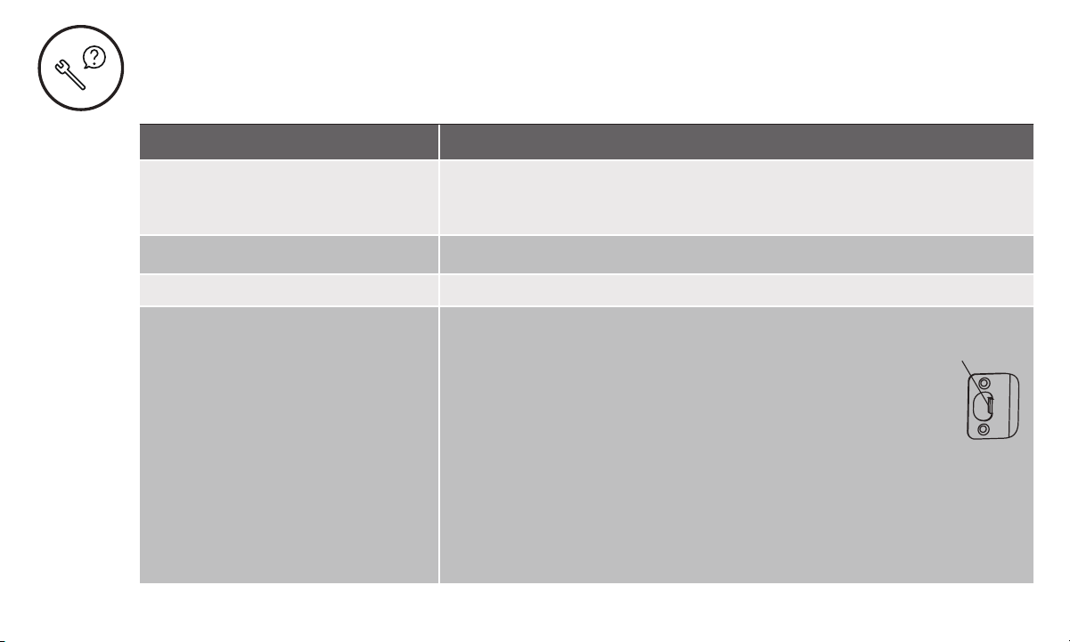
Resetting Lock to Factory Defaults
When lock is reset*, it will remove the lock from the Yale
Access App and remove all pin codes and settings that
were changed.
To Reset Lock:
1. Remove battery cover and one battery.
2. Press reset button for 1 minute with the reset tool
provided in the hardware box.
3. Replace cover.
Note: If the lock was enrolled in a Z-Wave network prior to
reset, it will need to be set up again.
*After reset, lock must be set up with the Yale Access App.
Remove 1 battery to
reset lock.
Do not install
Smart Module with
batteries installed.
Interior Lock
Reset Pin

Part of ASSA ABLOYP/N YRD400-KF-0022 Rev ATrusted every day
30
Keypad Alerts
Keypad Meaning
Gear flashes Amber Low Battery Level 1
Gear flashes Red Low Battery Level 2
Gear flashes Red then stays red
until batteries are replaced
Low Battery Level 3
Checkmark flashes Pairing Success
X then gear flashes Red Jammed Lock
Gear flashes White Pairing/successful pairing
Gear flashes Red during pairing Failed Pair
Part of ASSA ABLOYP/N YRD400-KF-0022 Rev ATrusted every day
31
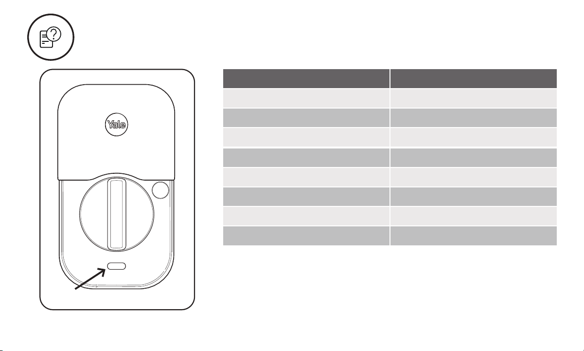
Interior Lock Light Alerts
Inside Lock Light Meaning
Blue flashing Low Battery Level 1
Blue flashing Low Battery Level 2
Blue flashing Low Battery Level 3
Pink flashing Passage Mode enabled
Red flashLocked state
Green flash Unlocked state
Green 3 second solid Pairing Success
Red 3 second solid Pairing Fail
Light

32
Part of ASSA ABLOYP/N YRD400-KF-0022 Rev ATrusted every day
Yale Home
24/7 Support: 1-855-213-5841 • US.YaleHome.com
Yale® and Assure Lock® 2 are registered trademarks of Yale Home. Other products’ brand names may be trademarks
or registered trademarks of their respective owners and are mentioned for reference purposes only. ©Copyright 2022.
All rights reserved. Reproduction in whole or in part without the express written permission of Yale Home is prohibited.
FCC:
FCC ID: 2ABFG-YRD450BLEV1
IC ID: 11626A-YRD450BLEV1
Class B Equipment
This equipment has been tested and found to comply
with the limits for a Class B digital device, pursuant to Part
15 of the FCC Rules. These limits are designed to provide
reasonable protection against harmful interference in a
residential installation. This equipment generates, uses,
and can radiate radio frequency energy and, if not installed
and used in accordance with the instructions, may cause
harmful interference to radio communications. However,
there is no guarantee that interference will not occur in a
particular installation. If this equipment does cause harmful
interference to radio or television reception, which can be
determined by turning the equipment off and on, the user is
encouraged to try to correct the interference by one or more of
the following measures:
• Reorient or relocate the receiving antenna.
• Increase the separation between the equipment
and receiver.
• Connect the equipment into an outlet on a circuit different
from that to which the receiver is connected.
• Consult the dealer or an experienced radio/TV technician
for help.
Warning:
Changes or modifications to this device, not expressly
approved by Yale Home could void the user’s authority to
operate the equipment.
Industry Canada:
FCC ID: 2ABFG-YRD450BLEV1
IC ID: 11626A-YRD450BLEV1
This Class A digital apparatus meets all requirements of the
Canadian Interference Causing Equipment Regulations.
Use:
Use of the Works with Apple badge means that an accessory
has been designed to work specifically with the technology
identified in the badge and has been certified by the
developer to meet Apple performance standards.
Apple is not responsible for the operation of this device or its
compliance with safety and regulatory standards.
Apple®, Apple Home™, Apple Watch®, HomeKit®, and
iPhone® are trademarks of Apple Inc., registered in the U.S.
and other countries and regions.
Google, Google Play and Google Home are trademarks of
Google LLC.
Amazon, Alexa and all related logos are trademarks of
Amazon.com, Inc. or its affiliates.
Wi-Fi is a registered trademark of Wi-Fi Alliance®.
The Bluetooth® word mark and logos are registered
trademarks owned by Bluetooth SIG, Inc. and any use of such
marks by [licensee name] is under license. Other trademarks
and trade names are those of their respective owners.