23
Engine Manual for Kawasaki Engine
SAFETY AWARENESS
FORWARD
We wish to thank you for purchasing this Kawasaki engine. Please read this Owner's manual carefully before
starting your new engine so that you will be thoroughly familiar with the proper operation of your engine's
control, its features, capabilities and limitations. Also read the manual of the equipment to which this engine
is attached. To ensure a long, trouble-free life for your engine, give it the proper care and maintenance
described in this manual.
Always keep this manual at your fingertip so that you can refer to it whenever you need information. This
manual should be considered a permanent part of the engine and should remain with the engine when it is
sold. All rights reserved. No part of this publication may be reproduced without our prior written permission.
This publication includes the latest information available at the time of printing. However, there may be minor
differences between the actual product and illustrations and text in this manual. All products are subject to
change without prior notice or obligation.
EMISSION CONTROL INFORMATION.................................................. 24
GENERAL INFORMATION..................................................................... 26
FUEL AND OIL RECOMMENDATIONS.................................................. 27
PREPARATION ...................................................................................... 27
Fuel............................................................................................. 27
Engine Oil................................................................................... 27
STARTING.............................................................................................. 28
Starting Engine........................................................................... 28
OPERATING........................................................................................... 28
Anti-engine inclination................................................................. 28
STOPPING.............................................................................................. 28
Stopping Engine ......................................................................... 28
ADJUSTMENT........................................................................................ 29
Engine Speed Adjustment .......................................................... 29
MAINTENANCE...................................................................................... 29
Periodic Maintenance Chart ....................................................... 29
Oil Level Check........................................................................... 29
Oil Change.................................................................................. 29
Air Cleaner Service..................................................................... 30
Spark Plug Service ..................................................................... 30
STORAGE............................................................................................... 32
TROUBLESHOOTING GUIDE................................................................ 33
ENVIRONMENTAL PROTECTION......................................................... 33
SPECIFICATIONS.................................................................................. 33
WARNING: Whenever you see the symbols shown on the left, heed their instructions! Always follow safe
operating and maintenance practices.
ENGINE MANUAL

24
READ THIS FIRST
Emission Control Information
Fuel Information
THIS ENGINE IS CERTIFIED TO OPERATE ON
UNLEADED REGULAR GRADE GASOLINE ONLY.
A minimum of 87 octane of the antiknock index is
recommended. The antiknock index is posted on
service station pumps in the U.S.A.
To protect the environment in which we all live,
Kawasaki has incorporated an exhaust emission
control system in compliance with applicable
regulations of the United States Environmental
Protection Agency and the California Air Resources
Board. Also, depending on when your engine was
produced, it may have an assigned emissions durability
period. * See below for the engine emissions durability
period that may apply to your engine.
Exhaust Emission Control System
The exhaust emission control system applied to this
engine consists of a fuel system and an ignition system
having optimum ignition timing characteristics. The fuel
system has been calibrated to provide lean air/fuel
mixture characteristics and optimum fuel economy with
a suitable air cleaner and exhaust system
A sealed-type crankcase emission control system is
also used to eliminate blow-by gasses. The blow-by
WARNING: Never allow children to operate the engine or equipment.
Keep people and pets out of area where you are using the engine or equipment.
Never wear loose, torn, or bulky clothing. It may catch on moving parts or controls, leading to the risk of
accident.
Never consume alcohol or drug before or while operating this engine.
Do not run the engine in a closed area. Exhaust gas contains carbon monoxide, an odorless and deadly
poison.
Gasoline is extremely flammable and can be explosive under certain condition.
Stop engine and allow the engine to cool before refueling.
Do not smoke. Make sure area is well ventilated and free from any source of flame or sparks including the
pilot light of any appliance while refueling, servicing fuel system, draining gasoline and/or adjusting
carburetor.
Do not fill the tank so the fuel level rises into the filler neck. If the tank is overfilled, heat may cause the fuel
to expand and overflow through the vents in the tank cap.
Wipe off any spilled gasoline immediately.
To prevent fire hazard:
Keep the engine at least 1 m (3.3 ft.) away from buildings, obstructions and other burnable objects.
Do not place flammable objects close to the engine.
Do not expose combustible materials to the engine exhaust.
Do not use the engine on any forest covered, bush covered or grass covered unimproved land unless spark
arrester is installed on the muffler.
To avoid getting an electric shock, do not touch spark plug, plug cap or spark plug lead during engine
running.
To avoid a serious burn, do not touch a hot engine or muffler. The engine becomes hot during operation.
Before you service or remove parts, stop engine and allow the engine to cool.
Do not place hands or feet near moving or rotating parts.
Do not run engine at excessive speeds. This may result in injury.
Always remove the spark plug lead from spark plug when servicing the engine to prevent accidental
starting.

25
gasses are led to a breather chamber through the
crankcase and from there to the air cleaner.
Engine Emissions Compliance Period
California
Model Year - 2006 and later Vertical Crankshaft
Durability Period - 500 hours
All Other States
Model Year - 2003 and later (new)
2007 and later (carry over)
Durability Period - 500 hours (Category A}
If your engine has an assigned emissions durability
period it will be located on the certification label
attached to the engine (IMPORTANT ENGINE
INFORMATION).
High Altitude Performance Adjustment Information
To improve the EMISSIONS CONTROL
PERFORMANCE of engines operated above 1,000
meters (3,300 feet), Kawasaki recommends the
following Environmental Protection Agency (EPA) and
the California Air Resources Board (CARB) approved
modifications.
NOTE: When properly performed, these specified
modifications only are not considered to be emissions
system "tampering" and engine performance is
generally unchanged as a result.
Installation Instructions:
High altitude adjustment requires replacement of
carburetor main jet. Installation of these optional parts
may be performed by an authorized Kawasaki dealer,
or the consumer, following repair recommendations
specified in the appropriate Kawasaki Service Bulletin.
Maintenance and Warranty
Proper maintenance is necessary to ensure that your
engine will continue to have low emission levels. This
Owner's Manual contains those maintenance
recommendations for your engine. Those items
identified by the Periodic Maintenance Chart are
necessary to ensure compliance with the applicable
standards.
As the owner of the engine, you have the responsibility
to make sure that the recommended maintenance is
carried out according to the instructions in this Owner's
Manual at your own expense.
The Kawasaki Limited Emission Control System
Warranty requires that you return your engine to an
authorized Kawasaki dealer for remedy under warranty.
Please read the warranty carefully, and keep it valid by
complying with the owner's obligations it contains.
Tampering with Emission Control System Prohibited
Federal law and California State law prohibit the
following acts or the causing thereof: (1) the removal or
rendering inoperative by any person other than for
purposes of maintenance, repair, or replacement, of
any device or element of design incorporated into any
new engine for the purposes of emission control prior to
its sale or delivery to the ultimate purchaser or while it is
in use, or (2) the use of the engine after such device or
element of design has been removed or rendered
inoperative by any person.
Among those acts presumed to constitute tampering
are the acts listed below:
Do not tamper with the original emission related parts:
• Carburetor and internal parts
•Spark Plug
• Magneto or electronic ignition system
• Fuel filter element
• Air cleaner elements
• Crankcase
• Cylinder head
• Breather chamber and internal parts
• Intake pipe and tube
26
General Information
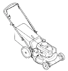
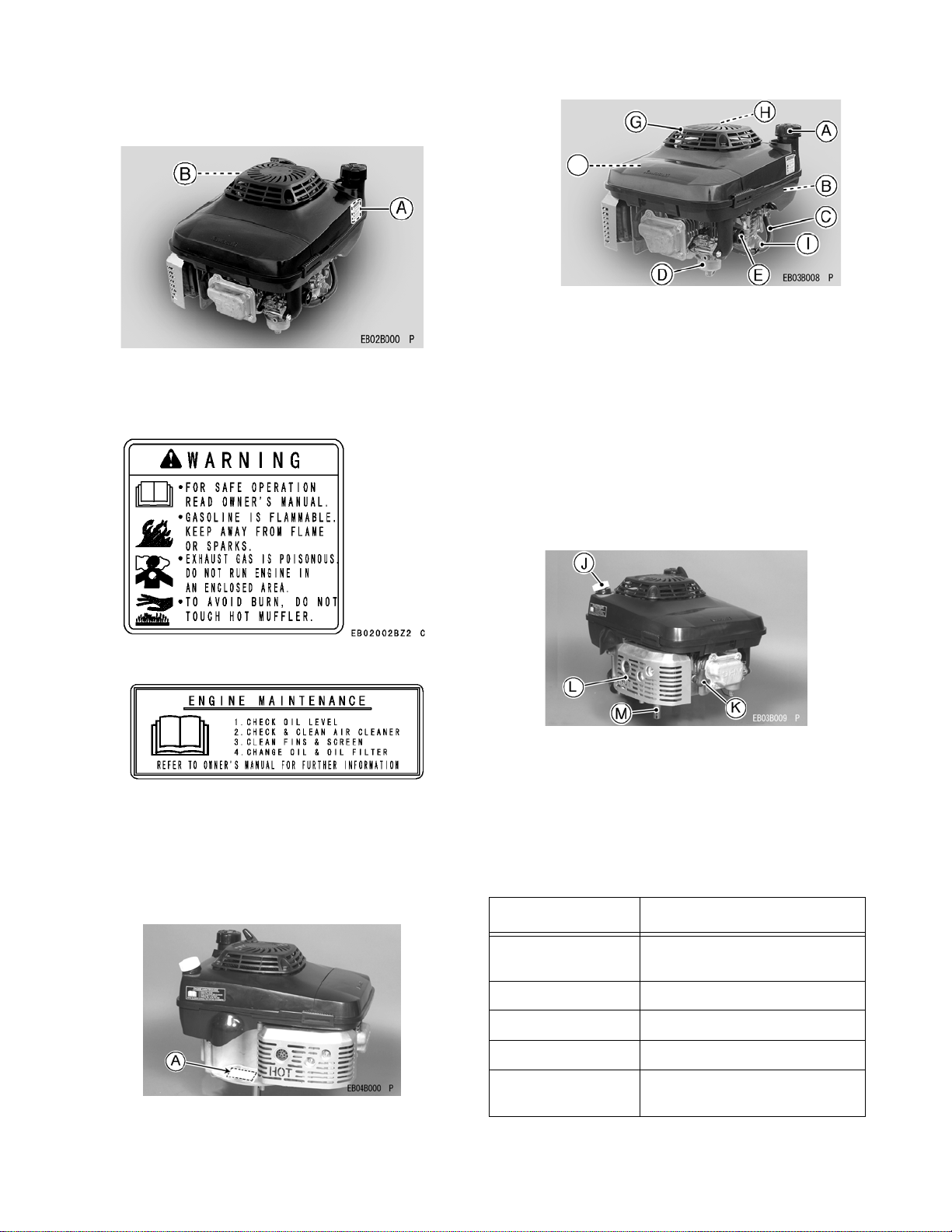
Location of Safety Related Labels
Figure 1
a. Warning
b. Engine Maintenance
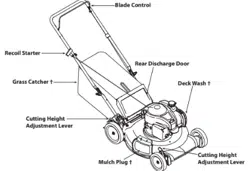
Engine Serial Number
The engine serial number is your only means of
identifying your particular engine from others of the
same model type.This engine serial number is needed
by your dealer when ordering parts. Refer to Figure 2.
Figure 2
Figure 3
A. Fuel Tank Cap
B. Fuel Tank (capacity 2.0L [0.528US gal.])
C. Fuel Tube
D. Carburetor
E. Priming Pump
F. Air Cleaner
G. Recoil starter
H. Recoil Starter Grip
I. Oil Drain Plugs (engine oil capacity 0.65L [0.69US
gal.])
Figure 4
J. Oil Gauge / Filler Cap
K. Spark Plug Cap / Spark Plug
L. Muffler
M. P.T.O. Shaft
Tune-up Specifications
ITEM SPECIFICATION
• Valve Clearance • IN 0.12mm(0.005 in.)
• EX 0.12mm{0.005 in.}
• Ignition Timing • Unadjustable
• High Idle Speed • 3200 r/min (rpm)
• Spark Plug Gap • 0.7- 0.8mm(0.028-0.032 in.)
• Other Specifica-
tions
• NO OTHER ADJUSTMENT
NEEDED
F
27
Fuel And Oil Recommendations
Fuel
Use only clean, fresh, unleaded regular grade
gasoline.
Octane Rating
The octane rating of a gasoline is a measure of its
resistance to "knocking".Use a minimum of 87 octane of
the antiknock index is recommended. The antiknock
index is posted on service station pumps in the U.S.A.
NOTE: If "knocking or pinging" occurs, use a different
brand of gasoline or higher octane rating.
CAUTION: Do not mix oil with gasoline
Oxygenated Fuel
Oxygenates (either ethanol or MTBE) are added to the
gasoline. If you use the oxygenated fuel be sure it is
unleaded and meets the minimum octane rating
requirement.The following are the EPA approved
percentages of fuel oxygenates.
ETHANOL: (Ethyl or Grain Alcohol)
You may use gasoline containing up to 10% ethanol by
volume.
MTBE: (Methyl Tertiary Butyl Ether)
You may use gasoline containing up to 15% MTBE by
volume.
METHANOL: (Methyl or Wood Alcohol) 5% by volume
You may use gasoline containing up to 5% methanol by
volume, as long as it also contains co solvents and
corrosion inhibitors to protect the fuel system.
Gasoline containing more than 5% methanol by volume
may cause starting and/or performance problems. It
may also damage metal, rubber, and plastic parts of
your fuel system.
Engine Oil
The following engine oils are recommended:
API Service Classification: SF, SG, SH, or SJ.
Oil Viscosity
Choose the viscosity according to the temperature
following chart in Figure 5.
Figure 5
NOTE: Using multi grade oils (5W-20, 10W-30, and
10W-40) will increase oil consumption. Check oil level
more frequently when using them.
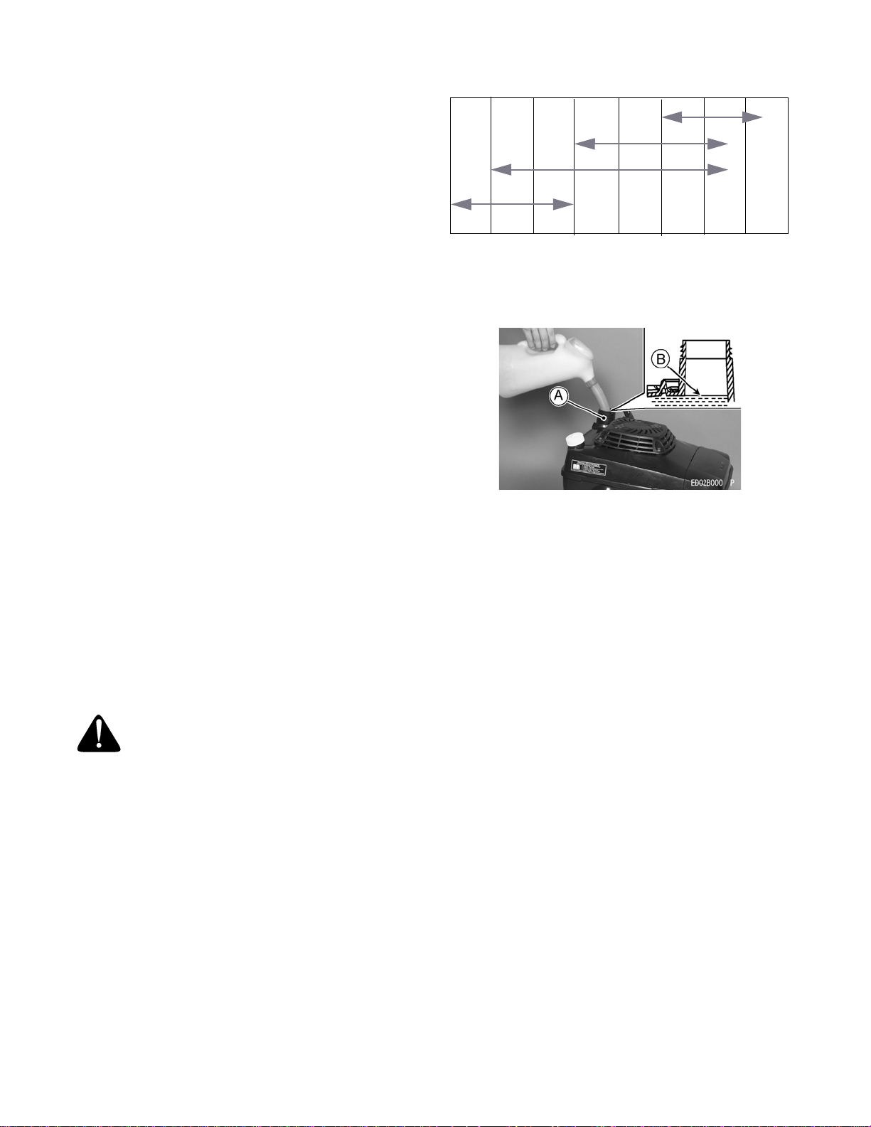
Figure 6
Preparation
Fuel
• Level the engine (equipment) before fueling.
• Remove the fuel tank cap.
• Slowly pour fuel into the fuel tank to bottom (B) of
the filler (A).
Do not over fill the fuel tank, fill only to bottom (B) of the
filler (A) to prevent spill out of the fuel from the tank cap.
Fuel Tank Capacity, 2.0 L (0.528 us.gal)
• Close the tank cap securely by turning it clockwise
as far as it will go.
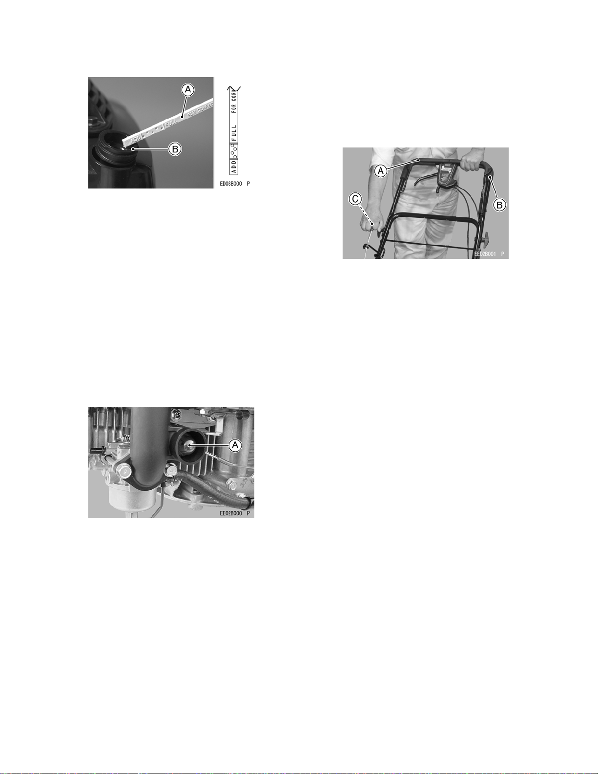
Engine Oil
Check the engine oil level daily before starting the
engine otherwise shortage of the engine oil may cause
serious damage to the engine such as seizure.
• Place the engine (equipment) on level surface.
Clean area around the oil gauge before removing it.
• Remove the oil gauge (A) and wipe it with clean
cloth.
• Pour the oil slowly to "FULL" mark on the oil gauge.
• Insert the oil gauge into the oil filler (B)WITHOUT
SCREWING IT IN.
• Remove the oil gauge to check the oil level. Level
should be between "ADD" and "FULL" marks. Do
not overfill.
• Install and tighten the oil gauge.
Engine Oil Capacity, 0.65 L (0.69 us.qt)
WARNING: Gasoline is extremely
flammable and can be explosive under certain
conditions. Do not smoke. Make sure the area
is well ventilated and free from any source of
flame or sparks; this includes any appliance
with a pilot light. Never fill the tank so the fuel
level rises into the filler neck. If the tank is
overfilled, heat may cause the fuel to expand
and overflow through the vents in the tank cap.
-20°C -10°C 0°C 10°C 20°C 30°C 40°C
SAE 5W-20
SAE 10W-30/10W-40
SAE 30
SAE 40
28
CAUTION: The engine is shipped without
engine oil.
Figure 7
Starting
Band Pad System
Upon releasing the brake control lever on the
equipment, the cutting blade and the engine will stop
automatically.
Therefore, the brake control lever must be held against
the handle while the engine is started and running.
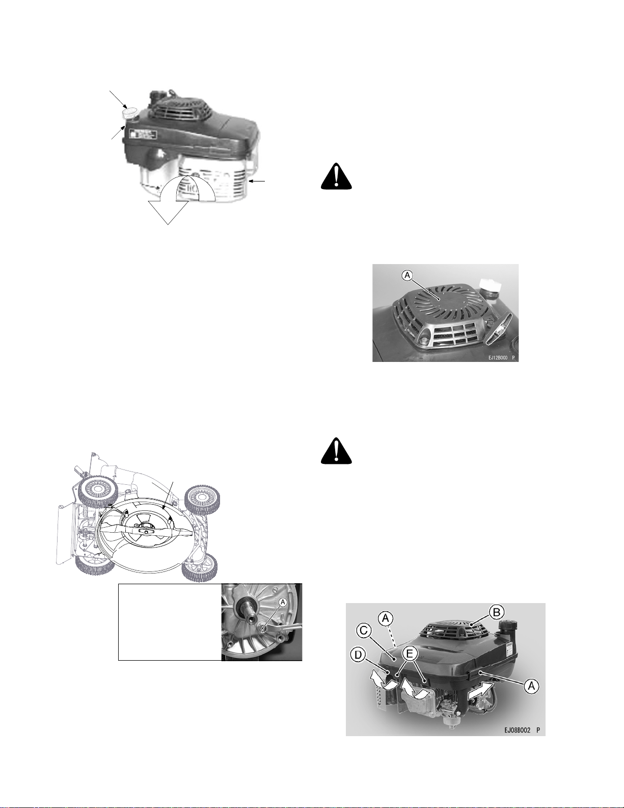
Starting Engine
• Fully push the priming button (A) by thumb only
once.
NOTE: When the engine is already warm or on hot
days, do not push the priming button to prevent faulty
starting engine caused by flooding carburetor.
Figure 8
CAUTION:
• DO NOT start the engine when the cutting blade
is in contact with long, uncut grass, it may
cause difficulties in starting and damage to the
recoil starter.
• DO NOT attempt to start the engine when the
brake control lever on the equipment is
released from your hands; this may cause
damage to the recoil starter or pad system of
the engine.
• DO NOT pull the recoil starter grip out of the
end.
• DO NOT let the recoil starter grip snap back
itself. This may cause damage to the recoil
starter assembly.
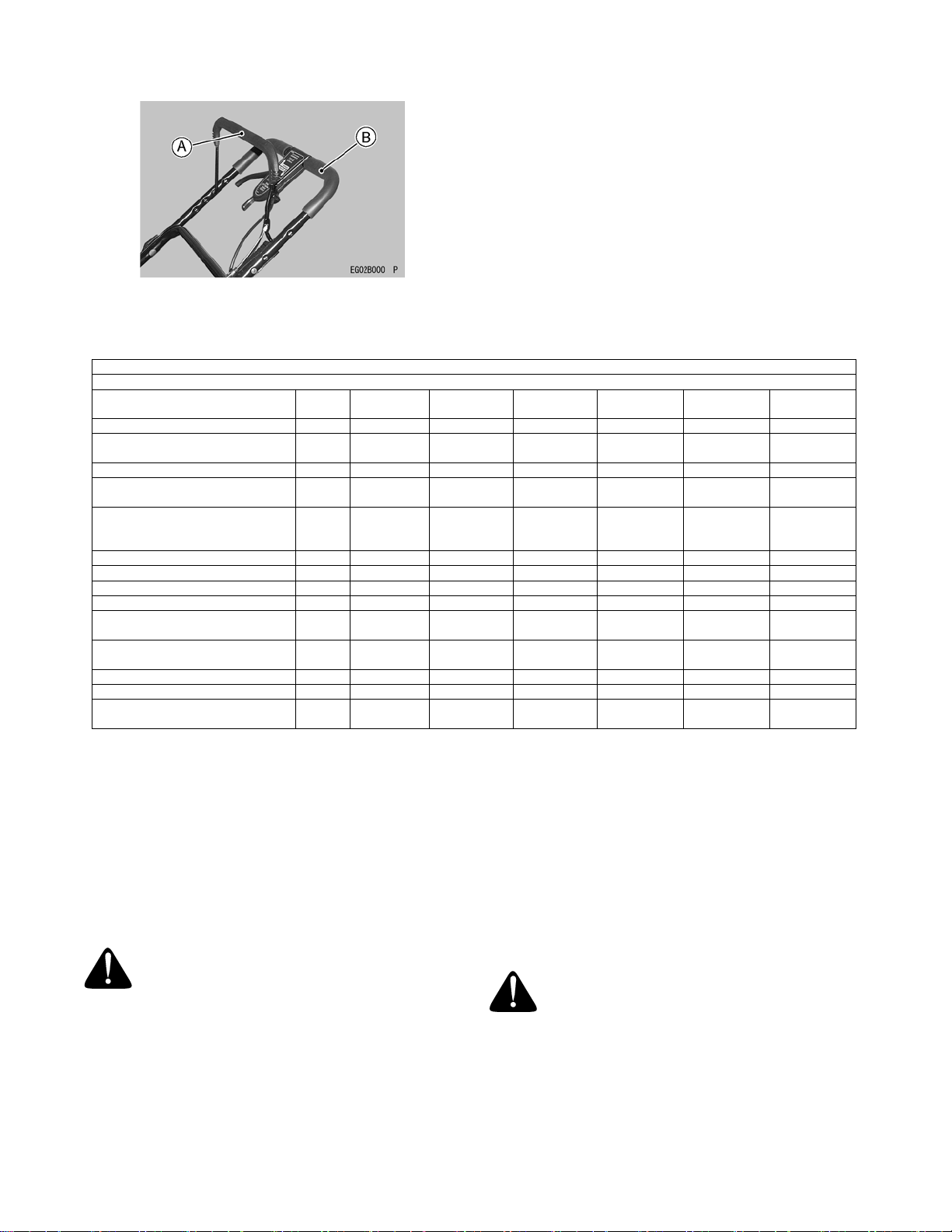
• Hold the brake control lever (A) on the equipment
against the handle (B) on the equipment.
• Pull the recoil starter grip (C) slowly until you feel
compression, then pull fast and steady.
Figure 9
A. Brake Control Lever
B. Handle
C. Recoil Starter Grip
Warming up
CAUTION: Allow engine to warm up before loading.
This will allow oil to reach all the engine parts, and
the piston clearance to reach design specification,
before the engine is ready for loading.
• After engine starts, warm up the engine, run it for a
few minutes.
Operating
• Anti-engine inclination
• This engine will operate continuously at angles up
to 30°in any direction.
• Refer to the operating instructions of the equipment
this engine powers.
• Because of equipment design or application, there
may be more stringent restrictions regarding the
angle of operation.
CAUTION: Do not operate this engine continuously
at angles exceeding 30° in any direction. Engine
damage could result from insufficient lubrication.
Stopping
Stopping Engine
Release the brake control lever (A) on the equipment
from the handle (B) on the equipment to stop the engine
and the cutting blade.
A. Brake Control Lever
29
B. Handle
Figure 10
Adjustment
Engine Speed Adjustment
NOTE: Do not tamper with the governor setting or the
carburetor setting to increase the engine speed. Each
carburetor is adjusted at the factory with either a cap or
stop plate installed on the mixture screw. Any
adjustments must be performed an authorized
Kawasaki dealer.
MAINTENANCE
Oil Level Check
Check oil level daily and before each operation. Be sure
oil level is maintained. See PREPARATION .
Oil Change
Change oil after first 8 hours of operation. Thereafter
change oil every 50 hours.
• Run the engine to warm oil.
• Be sure the engine (equipment) is level.
• Stop the engine.
Two alternate methods of draining oil are described in
the following lines. For convenient handling, the first
method is recommended.
1. Draining Oil From
Crank Case
• Tip the mower as shown in Figure 11 below.
Remove the dipstick from the engine and pour
entire oil from the crank case into an appropriate
container.
Periodic Maintenance Chart
MAINTENANCE
INTERVAL
DAILY FIRST 8
HOURS
EVERY 25
HOURS
EVERY 50
HOURS
EVERY 100
HOURS
EVERY 200
HOURS
EVERY 300
HOURS
Check oil level and add engine oil
z
Check for loose or lost nuts and
screws
z
Check for fuel and oil leakage
z
Check for brake control lever
function
z
Check or clean recoil starter and
air intake screen Tighten nuts
and screws
z
z
Clean air cleaner foam element
z
z
z
Clean air cleaner paper element
z
z
Change engine oil
z
z
Clean and re-gap spark Plug
z
Replace air cleaner paper
element
z
Clean dust and dirt from cylinder
and cylinder head fins
z
Clean combustion chamber
z
Check and adjust valve clearance
z
Clean and lap valve seating
surface
z
NOTE: The service intervals indicated are to be used as a guide. Service should be performed more frequently as
necessary by operating condition. Service more frequently under dusty conditions.
WARNING: Hot engine oil can cause severe
burns. Allow engine temperature to drop from
hot to warm before draining and handling oil.
WARNING: Before tipping the equipment,
make sure to run the engine till fuel runs dry.
WARNING: While tipping the engine, keep
muffler side down as shown below.
30
• Put the mower back to its operating position (on all
four wheels).
Figure 11
2. Using Oil Drain Plug
IMPORTANT:
The oil drain plug on this engine is located
at the bottom and can only be accessed by removing
the baffle and other components . This method of
draining oil involves complicated steps. The first
method, described earlier, is simpler and takes less
time; hence it is the preferred method.
• Run the engine for a few minutes and stop the
engine. Tip the mower as shown in Figure 12.
• Access the oil drain plug by removing the baffle and
other components following instructions in
“Changing Belts” section on page 14. See Figure
12 for location of the baffle.
• Remove the oil drain plug from bottom of the
engine. See Figure 12 inset for location of the oil
drain plug. Drain oil into suitable container.
Figure 12
• Reinstall the oil drain plug.
• Reinstall the baffle and other components removed
earlier. Make sure to secure these now.
• Put the mower back on its four wheels and on level
ground.
Refilling Fresh Oil
• Remove dipstick and refill with new oil (See FUEL
AND OIL RECOMMENDATIONS chapter).
NOTE: If you followed the second method of draining
oil, the dipstick is already removed from the engine.
• Check the oil level (See PREPARATION chapter),
and secure dipstick to the filler plug.
Cooling System Cleaning
Before each use, make sure recoil starter (A) is free
from grass and debris to prevent engine overheating.
Figure 13
Air Cleaner Service
CAUTION: To prevent excessive engine wear, do
not run the engine with the air cleaner
• Unfasten the air cleaner case (C) fastened with the
air cleaner body (D) by sliding the two fasteners (A)
toward the recoil starter (B).Then, with two hands,
pulling the two latches (E) toward you and upward
as shown, separate the air cleaner case from the air
cleaner body.
Figure 14
Dipstick
Crank Case
Muffler
Tilt mower so engine
tips this way
A. Oil Drain Plug (on
bottom of engine)
Baffle
WARNING: Engine oil is toxic substance.
Dispose of used oil properly. Contact your local
authorities for approved disposal methods for
possible recycling.
WARNING: Clean the elements in a well-
ventilated area and take care that there are no
sparks or flame anywhere near the working
area, this includes any appliance with a pilot
light. Do not use gasoline or low flash-point
solvents to clean the element. A fire or
explosion could result.
31
A. Fasteners
B. Recoil Starter
C. Air Cleaner Case
D. Air Cleaner body
E. Latches
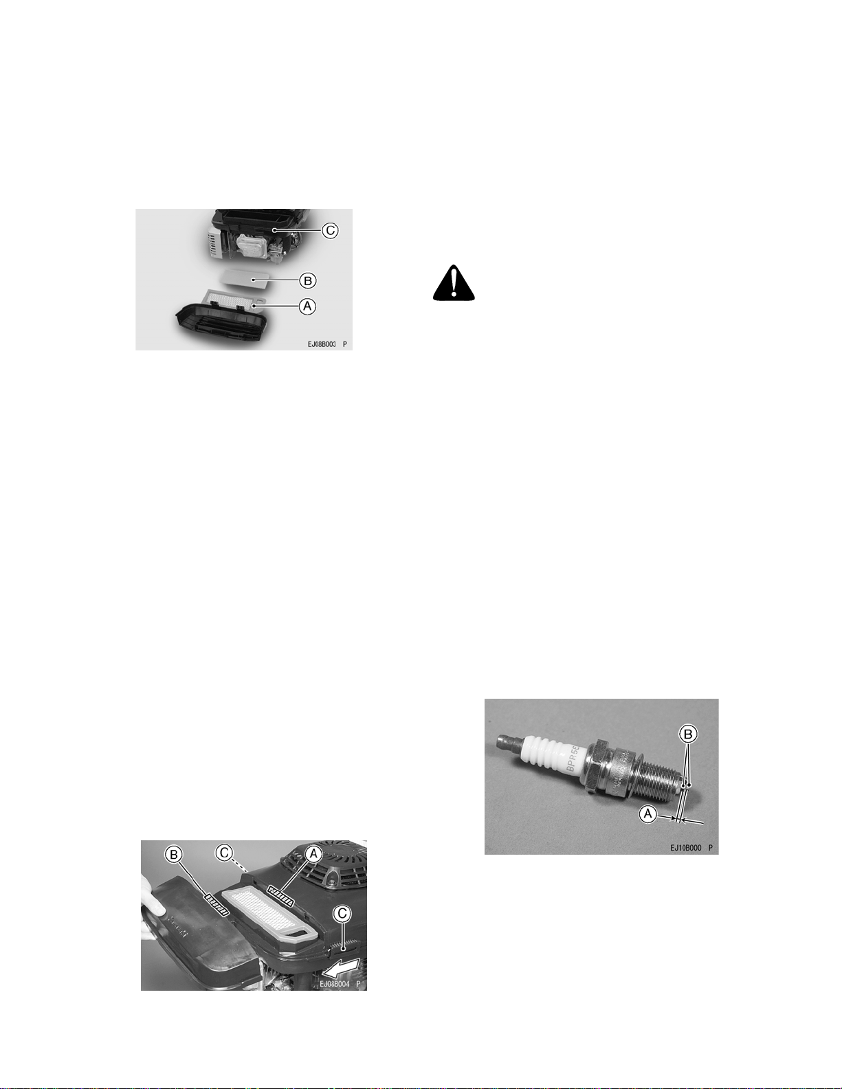
Remove the paper element (A) and the foam element
(B) from the air cleaner body (C).
Figure 15
A. Paper Element
B. Foam Element
C. Air Cleaner body
Foam Element
Clean the foam element every 25 hours.
Wash the element in detergent and water, and dry it
thoroughly.
CAUTION: Do not oil foam element.
Paper Element
• Clean the paper element every 100 hours.
• Clean the element by tapping gently to remove
dust. If very dirty, replace the element .
• Replace paper-element yearly or every 300 hours.
CAUTION: Do not wash paper-element. Do not use
pressurized air to clean or dry paper element.
NOTE: Operating in a dusty condition may require
more frequent maintenance than above.
• Reinstall the foam element and then the paper
element on the air cleaner body.
• Reinstall the air cleaner case on the air cleaner
body by first fitting the projection (B) on the edge of
the air cleaner case into the slit (A) in the air cleaner
body. Then, sliding the fasteners (C) toward the air
cleaner case, securely fasten the air cleaner case
with the air cleaner body.
Figure 16
A. Slit in the air cleaner body
B. Projection on the air cleaner case
C. Fasteners
CAUTION: After servicing the air cleaner, be sure
all the removed parts are reinstalled properly in
place. Failure to secure fastening of the air cleaner
case with the air cleaner body may cause dirt or
other foreign materials to enter the engine, while it
is running, through the air cleaner, resulting in
engine troubles or failures.
• Clean or replace the spark plug and reset gap (A)
every 100 hours of operation.
• Disconnect the spark plug cap from spark plug and
remove the spark plug.
• Clean the electrodes (B) by scraping or with a wire
brush to remove carbon deposits.
• Inspect for cracked porcelain or other wear and
damage. Replace the spark plug with a new one if
necessary.
• Check the spark plug gap and reset it if necessary.
The gap must be between 0.7 and 0.8 mm (0.028
and 0.032").
To change the gap, bend only the side-electrode, using
a spark plug tool.
-Install and tighten the spark plug to 23 N-m (2.3kgf-m,
17fMb).
-Fit the spark plug cap on the spark plug securely.
-Pull up the spark plug cap lightly to make sure of the
installation of the spark plug cap.
Recommended Spark Plug
NGK... BPR5ES
Figure 17
A. Spark Plug Gap
B. Electrodes
CAUTION: Be sure to use the same type of spark
plug for change. Resistor spark plug is required in
some areas by local law.
WARNING: Hot engine components can
cause severe burns. Stop engine and allow it to
cool before checking spark plug.
32
Storage
Engine to be stored over 30 days should be completely
drained of fuel (gasoline) to prevent gum deposits
forming on essential carburetor parts and fuel system.
• Remove the spark plug cap from spark plug to
prevent accidental starting the engine.
• Empty the fuel from the fuel tank with a pump or
siphon.
• Fit the plug cap on the spark plug securely
• Start and run the engine at idle speed to used up
the fuel in the fuel system.
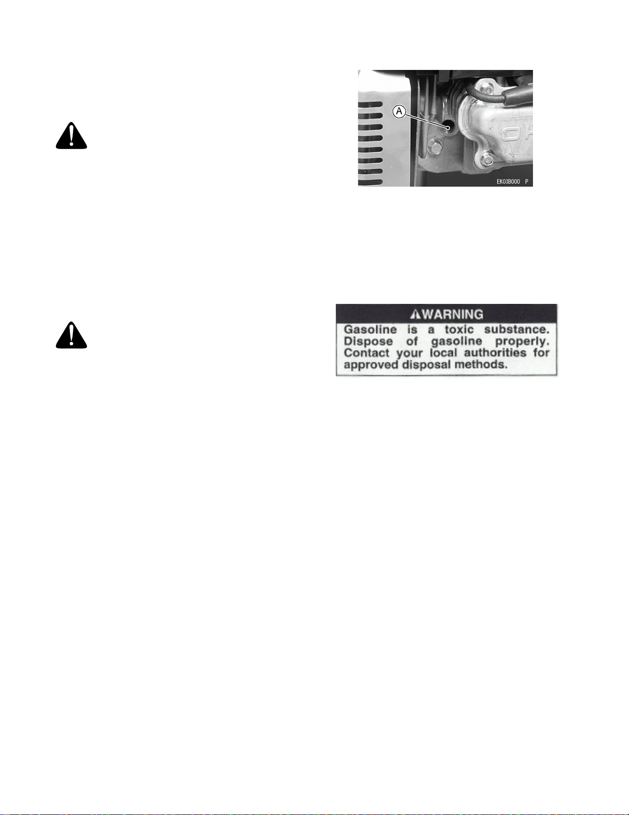
• Remove the spark plug and pour approx. 1-2 mL
(0.06-0.1 cu.in) of new engine oil through the plug
hole (A), slowly pull the recoil starter grip several
times and reinstall the spark plug.
Figure 18
A. Spark Plug Hole
• Slowly pull the recoil starter grip until you feel
compression and leave it there.
• Clean every part of the engine.
• After period of storage, change engine oil.
• (Refer to "Oil Change" section in
"MAINTENANCE" section).
WARNING: Gasoline is extremely
flammable and can be explosive under certain
conditions. Drain gasoline before storing the
equipment for extended periods. Drain
gasoline in a well-ventilated area away from
any source of flame or sparks, including any
appliances with a pilot light. Store gasoline in
an approved container in safe location.
WARNING: Before maintaining engine, stop
the engine and allow it cool.

33
Troubleshooting Guide
If the engine malfunctions, carefully examine the symptoms and the operating conditions, and use the table above
as a guide to troubleshooting.‡ Have an authorized Kawasaki dealer perform these service
Environmental Protection
To protect our environment, properly discard used batteries, engine oil, gasoline, coolant, or other components that
you might dispose of in the future.
Consult your authorized Kawasaki dealer or local environmental waste agency for their proper disposal procedure.
Specifications
Specifications subject to change without notice
Symptom Probable Cause Remedy
Engine won't start
output is low
Insufficient
compression
1. Faulty piston, cylinder, piston ring,
and head gasket
2. Faulty valves
3. Loose spark plug
4. Loose cylinder head bolts
1. Tighten properly
2. Tighten properly
3. Tighten properly
4. Tighten properly
No fuel to
combustion chamber
1. No fuel in fuel tank
2. Blocked rue tube
3. Blocked air vent in fuel tank cap
4. Faulty carburetor
1. Fill fuel tank
2. Clean
3. Clean
4. ‡
Spark plug fouled by
fuel
1. Over-rich fuel/air mixture
2. Clogged air cleaner
3. Faulty carburetor
4. Incorrect grade/type of fuel
5. Water in fuel
1. Slowly pull the recoil starter grip with
spark plug removed to discharge
excess fuel. clean spark plug
2.Clean
3.‡
4. Change Gasoline
5. Change Gasoline
No spark or weak
spark
1. Faulty spark plug
2. Faulty ignition coil
3. Faulty engine switch
1. Replace spark plug
2.‡
3.‡
Low Output Engine Overheats 1. Clogged air cleaner
2. Recoil Starter or cooling air path
clogged with dirt
3. Insufficient engine oil
4. carbon built -up in combustion
chamber
5. Poor ventilation around engine
1. Clean
2. Clean
3. Replenish or change oil
4.‡
5. Select a better location
1. Engine speed
won’t increase
1. Faulty Governor ‡
Type of Engine Air-cooled, 4-stroke OHV, single cylinder, gasoline Engine
• Bore X Stroke • 65 x 54mm (2.6 x 2.1 in.)
• Displacement • 179mL (109. cu.in.)
• Ignition system • Solid-state ignition
• Starting system • Recoil starter
• Dry weight • 13.5kg (29.lb)

34
Kawasaki Limited Warranty: California And Federal
Emission Control Systems: Small Off-Road Engines
The California Air Resources Board, the Environmental Protection Agency (EPA), and Kawasaki Motors Corp., U.S.A. (hereinafter "Kawasaki") are
pleased to explain the Emission Control Systems Warranty on your Kawasaki small off-road engine. In California and other states, new small off-
road engines must be designed, built and equipped to meet stringent anti-smog standards. Kawasaki must warrant the emission control system on
your small off-road engine for the period of time listed below provided there has been no abuse, neglect or improper maintenance of your small off-
road engine. Your emission control system may include parts such as the carburetor or fuel-injection system, the ignition system, and catalytic
converter. Also included may be hoses, belts, connectors and other emission related assemblies. Where a warrantable condition exists, Kawasaki
will repair your small off-road engine at no cost to you including diagnosis (if the diagnostic work is Performed at a Kawasaki small off-road engine
dealer), parts and labor.
OWNERS WARRANTY RESPONSIBILITIES. The following obligations must be fulfilled by the owner to maintain the validity of the Kawasaki
California / EPA Emissions Systems Warranty:
(a) As the small off-road engine owner, you are responsible for the performance of the required maintenance listed in your owner's manual.
Kawasaki recommends that you retain all receipts covering maintenance on your small off-road engine, but Kawasaki cannot deny warranty
solely for the lack of receipts or for your failure to ensure the performance of all scheduled maintenance.
(b) You are responsible for presenting your small off-road engine to an authorized Kawasaki small off-road engine Dealer as soon as a problem
exists. The warranty repairs should be completed in a reasonable amount of time, not to exceed 30 days.
(c) AS the small off-road engine owner, you should also be aware that Kawasaki may deny you warranty coverage if your small off-road engine or
a part has failed due to abuse, neglect, improper maintenance or unapproved modifications.
(d) If you have any questions regarding your warranty rights and responsibilities, you should contact Kawasaki Motors Corp., U.S.A., Consumer
Services Department, 5080 36th Street, S.E., Grand Rapids, Ml 49512, 616/949-6500.
1. COVERAGE. Kawasaki warrants to the initial owner and each subsequent purchaser that the small off-road engine is free from defects in
materials and workmanship which cause a failure of a warranted part for a period of two years. Kawasaki is liable for damages to other engine
components caused by the failure of a warranted part still under warranty. The 1995 and later small off-road engines are warranted for two
years in California. In all other states, 1997 and later model year small off-road engines are warranted for two years. If any emission-related
part on your engine is defective, the part will be repaired or replaced by Kawasaki. This warranty time period shall begin on the date the small
off?road engine is delivered to the initial purchaser, or on the date the small off?road engine is first placed in service.
Warranty defects shall be remedied during customary business hours at any authorized Kawasaki small off-road engine dealer located within the
United States of America. Any manufacturer-approved replacement part may be used in the performance of any warranty maintenance or repairs
on emission-related parts, and must be provided without charge to the owner if the part is still under warranty. Any part or parts replaced under this
warranty shall become the property of Kawasaki.
The emission related warranted parts are specifically defined by the California Air Resources Board's Emission Warranty Parts List. (EPA's
regulations do not include a parts list, but EPA considers emission-related parts to include all parts listed here.) These warranted parts are:
carburetor and internal parts, spark advance/retard system. cold start enrichment system, magneto or electronic ignition system, catalytic
converter, intake manifold, exhaust manifold, air cleaner element, and spark plugs if failure occurs prior to the first required scheduled
replacement, hoses, clamps, fittings, gaskets, sealing devices, mounting hardware and tubing used directly in these parts.
Since emission related parts may vary slightly from model to model,certain models may not contain all of these parts and certain models may
contain functionally equivalent parts.
2. LIMITATIONS. This Emission Control Systems Warranty shall not cover any of the following:
(a) Repair or replacement required as a result of (i) misuse or neglect, (ii) lack of required maintenance. (iii) repairs improperly performed or
replacements improperly installed, (iv) use of replacement parts or accessories not conforming to Kawasaki specifications which adversely
affect performance and/or durability, (v) alterations or modifications not recommended or approved in writing by Kawasaki.
(b) Replacement of parts, other services and adjustments necessary for required maintenance at and after the first scheduled replacement point.
LIMITED LIABILITY.
(a) The liability of Kawasaki under this Emission Control Systems Warranty is limited solely to the remedying of defects in materials or
workmanship by any authorized Kawasaki small off-road engine dealer at its place of business during customary business hours. This
warranty does not cover inconvenience or loss of use of the small off-road engine or transportation of the small off-road engine to or from the
Kawasaki Dealer. KAWASAKI SHALL NOT BE LIABLE FOR ANY OTHER EXPENSE, LOSS OR DAMAGE, WHETHER DIRECT,
INCIDENTAL, CONSEQUENTIAL (EXCEPTION LISTED UNDER COVERAGE) OR EXEMPLARY ARISING IN CONNECTION WITH THE
SALE OR USE OF OR INABILITY TO USE THE KAWASAKI SMALL OFF-ROAD ENGINE FOR ANY PURPOSE.
(b) NO EXPRESS EMISSION CONTROL SYSTEMS WARRANTY IS GIVEN BY KAWASAKI WITH RESPECT TO THE KAWASAKI SMALL
OFF-ROAD ENGINE EXCEPT AS SPECIFICALLY SET FORTH HEREIN. ANY EMISSION CONTROL SYSTEMS WARRANTY IMPLIED BY
LAW, INCLUDING ANY WARRANTY OF MERCHANTABILITY OR FITNESS FOR A PARTICULAR PURPOSE, IS EXPRESSLY LIMITED
TO THE EMISSION CONTROL SYSTEMS WARRANTY TERMS SET FORTH HEREIN. THE FOREGOING STATEMENTS OF WARRANTY
ARE EXCLUSIVE AND IN LIEU OF ALL OTHER REMEDIES.
(c) No dealer is authorized to modify this Kawasaki Limited Emission Control Systems Warranty.
(d) Kawasaki is not liable for parts which are not genuine Kawasaki parts except when genuine Kawasaki parts cause damage to non-Kawasaki
parts.
LEGAL RIGHTS: THIS WARRANTY GIVES YOU SPECIFIC LEGAL RIGHTS, AND YOU MAY ALSO HAVE OTHER RIGHTS. THIS WARRANTY
IS IN ADDITION TO THE KAWASAKI LIMITED SMALL OFF-ROAD ENGINE WARRANTY.