MIG TORCHES WITH 3M EURO CONNECTOR
MB15 , MB25
MODEL NO: MIG/T15.V2, MI/T25.V2
Thank you for purchasing a Sealey product. Manufactured to a high standard, this product will, if used according to these
instructions, and properly maintained, give you years of trouble free performance.
IMPORTANT: PLEASE READ THESE INSTRUCTIONS CAREFULLY. NOTE THE SAFE OPERATIONAL REQUIREMENTS, WARNINGS & CAUTIONS. USE
THE PRODUCT CORRECTLY AND WITH CARE FOR THE PURPOSE FOR WHICH IT IS INTENDED. FAILURE TO DO SO MAY CAUSE DAMAGE AND/OR
PERSONAL INJURY AND WILL INVALIDATE THE WARRANTY. KEEP THESE INSTRUCTIONS SAFE FOR FUTURE USE.
1. SAFETY
■ BEFORE USE, ALWAYS ENSURE THAT YOU ARE FAMILIAR WITH THE SAFETY WARNINGS AND INSTRUCTIONS FOR
THE WELDER TO WHICH THIS TORCH IS TO BE FITTED.
8 DO NOT exceed the rated current of the torch.
8 DO NOT use if any part of the torch, cable or connector is damaged in any way. Use only genuine Sealey replacement parts for
repairs.
8 DO NOT allow the cable to come into contact with any sharp or hot items.
9 Alwaysusethecorrectpersonalprotectiveequipmentasspeciedinthewelderinstructions.
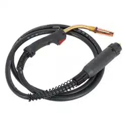
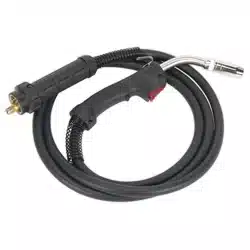
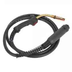
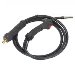
2. INTRODUCTION
Professional torches with contoured grip and heat-proof cable. Euro connection enables quick and simple plug connection to welder.
No wiring means torch can be disconnected and stored safely. Made in Europe.
3. SPECIFICATION
4. OPERATION
WARNING: Disconnect from power source while setting up.
NOTE: The type and quantity of the shielding gas quantity depends on the welding task and the gas nozzle geometry. Make all
shielding gas connections gas-tight.
NOTE: As the MIG/MAG welding torch is part of an integrated welding system, the operating instructions and safety guidelines of the
of the welding power source, must be observed during operation.
4.1. Using a standard welding torch, the two-position mode of the trigger can be activated (press to weld, release to stop welding).
4.2. Further operating modes and handle modules depend on the corresponding welding power source.
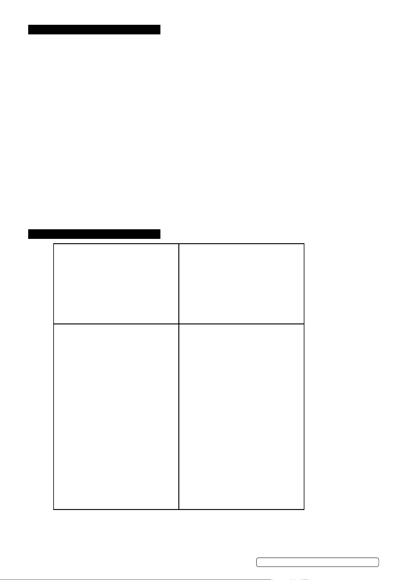
4.3. To connect the torch to the power source:
4.3.1. Remove the tip adaptor and contact tip.
4.3.2. Inch the wire from the exit of the wire guide on the feed unit as Figure 1. Ensure that it does not short out on any machine panels.
4.3.3. Carefully slide the electrode wire into the torch liner and slowly locate the torch gun
plug body into the feed unit central connector
and tighten the gun plug nut as Figure 2.
4.3.4. Keeping the torch as straight as possible, use the power source inch facility or torch trigger to feed the electrode wire 50mm from the
end of the liner conduit.
4.3.5. Oncetheelectrodewirehasstopped,retthetipadaptor,diuser,contacttipandgasnozzle.
MIG/T15.V2, MIG/T25.V2 Issue 1 31/10/22
Original Language Version
© Jack Sealey Limited
g.2
Refer to
instruction
manual
Wear a
welding
mask
Wear protective
gloves
Warning!
Electricity
shock hazard
Warning!
Keep away
from rain
Caution
required
Arc rays can
burn eyes and
injure skin
Breathing
welding fumes
can be
hazardous to
your health
Electric shock
from welding
electrodes can
kill
Electromagnetic
fields can cause
pacemaker
malfunction
Welding sparks
can cause
explosions
or fire
Model No. MIG/T15 MIG/T25
Rated Current CO
2
140A 140A
Rated Current M21 160A 184A
Wire diameter 0.6 - 1.0mm 0.8 - 1.2mm
Gas Flow 10 - 18 l/m 10 - 18 l/m
Length 3m 3m
Torch Type MB15 MB25
g.1
5. MAINTENANCE
▲ DANGER: Risk of injury due to unexpected start-up.
Switchothepowersupplyandcloseothegassupply,whenconnectingordisconnectingtorch
Switchothepowersupplywhenchangingconsumableparts
5.1. GENERAL MAINTENANCE
5.1.1. CLEANING
5.1.1.1. Remove the nozzle from the front of the neck.
5.1.1.2. Removeallspatterfromthehead,gasdiuserandthenozzle.Thesecomponentsmustbecleanandfreeofalldebristoensure
ecientgasowandtopreventshortcircuit.
5.1.1.3. Check all front end consumables for damage and wear. Replace with new genuine parts if necessary.
5.1.1.4. To maintain the best performance repeatedly check and clean the front end tip and shield periodically. Also use an anti-spatter
spray on the tip and shield to reduce the build up of debris.
5.1.2. LINER REPLACEMENT (STEEL LINER)
WARNING: Risk of injury such as piercing or puncture caused by electrode tip, wear protective gloves and glasses
5.1.2.1. Switchothepowersourceanddisconnectthetorchfromthepowersource(removethewirefrominsidethetorchbuywinding
back inside the machine.)
5.1.2.2. Lay down the hose assembly straight and remove gas nozzle, contact tip and tip adaptor from torch neck.
5.1.2.3. Unscrew liner retention nut from central plug and pull the liner out of the torch.
5.1.2.4. Fitthenewlinerusingapushandtwistactionuntilthelinerisfullyinserted.Retthelinerretentionnut.
5.1.2.5. Cutotheexcesslengthofthespiralwirelinerushwiththetorchneckorthetipadaptor.
5.1.2.6. Retthetorchtothemachine
NOTE: Ensure the cut end of the liner does not protrude into the hole where the wire passes. it is recommended to grind the front
of the liner to 40 Deg and deburr.
5.1.2.7. Screwdownlinerretentionnutbyhandandcutotheexcesslengthofthespiralwirelinerushwithtorchneckortipadaptor.
5.1.2.8. Unscrew liner retention nut and pull out spiral wire liner.
5.1.2.9. Sharpen the spiral wire liner at the front to an angle of approx. 40° and deburr.
6. TROUBLESHOOTING
1. Wire feed unit operates but no gas
flow:
Gas cylinder empty
Gas regulator closed
Faulty solenoid
Restriction in torch cables
3. Burnback
Improper voltage setting
Contact tip overheating
Incorrect or blocked liner
Excessive cable kinking
Erratic wire feed
Improper stick out
2. Bird nesting
Contact tip overheating/Burnback
Incorrect contact tip size
Incorrect or blocked liner
Restriction in torch cable
Excessive cable kinkage
Excessive feed roll pressure
Misaligned drive rolls or wire guides
4 Erratic Wire Feeding or Arc
Adjust welding voltage
Improper drive roll tension
Improper drive roll size
Worn drive rolls
Incorrect or blocked liner
Incorrect wire guide size
Misaligned drive rolls or wire guide
Gaps at liner or wire guide junctions
Incorrect contact tip size
Contact Tip overheating
Spatter adhesion on exit geometry of
tip bore
Excessive cable kinkage
Poor earth or cable connections
Weld joint area dirty
MIG/T15.V2, MIG/T25.V2 Issue 1 31/10/22
Original Language Version
© Jack Sealey Limited

Sealey Group, Kempson Way, Suffolk Business Park, Bury St Edmunds, Suffolk. IP32 7AR
01284 757500 sales@sealey.co.uk www.sealey.co.uk
ENVIRONMENT PROTECTION
Recycle unwanted materials instead of disposing of them as waste. All tools, accessories and packaging should be sorted, taken to
a recycling centre and disposed of in a manner which is compatible with the environment. When the product becomes completely
unserviceable and requires disposal, drain any fluids (if applicable) into approved containers and dispose of the product and fluids
according to local regulations.
Note: It is our policy to continually improve products and as such we reserve the right to alter data, specifications and component parts
without prior notice.
Important: No Liability is accepted for incorrect use of this product.
Warranty: Guarantee is 12 months from purchase date, proof of which is required for any claim.
REGISTER YOUR
PURCHASE HERE
MIG/T15.V2, MIG/T25.V2 Issue 1 31/10/22
Original Language Version
© Jack Sealey Limited