User Manual of Network Traffic Camera
0
User Manual
Network Traffic Camera

User Manual of Video Vehicle Detector
1
User Manual
COPYRIGHT ©2017 Hangzhou Hikvision Digital Technology Co., Ltd.
ALL RIGHTS RESERVED.
Any and all information, including, among others, wordings, pictures, graphs are the
properties of Hangzhou Hikvision Digital Technology Co., Ltd. or its subsidiaries
(hereinafter referred to be “Hikvision”). This user manual (hereinafter referred to be
“the Manual”) cannot be reproduced, changed, translated, or distributed, partially or
wholly, by any means, without the prior written permission of Hikvision. Unless
otherwise stipulated, Hikvision does not make any warranties, guarantees or
representations, express or implied, regarding to the Manual.
About this Manual
This Manual is applicable to Video Vehicle Detector (hereinafter referred to as
“camera”).
The Manual includes instructions for using and managing the product. Pictures, charts,
images and all other information hereinafter are for description and explanation only.
The information contained in the Manual is subject to change, without notice, due to
firmware updates or other reasons. Please find the latest version in the company
website (http://overseas.hikvision.com/en/).
Please use this user manual under the guidance of professionals.
Trademarks Acknowledgement
and other Hikvision’s trademarks and logos are the properties of
Hikvision in various jurisdictions. Other trademarks and logos mentioned below are
the properties of their respective owners.
Legal Disclaimer
TO THE MAXIMUM EXTENT PERMITTED BY APPLICABLE LAW, THE
PRODUCT DESCRIBED, WITH ITS HARDWARE, SOFTWARE AND
FIRMWARE, IS PROVIDED “AS IS”, WITH ALL FAULTS AND ERRORS, AND
HIKVISION MAKES NO WARRANTIES, EXPRESS OR IMPLIED, INCLUDING

User Manual of Video Vehicle Detector
2
WITHOUT LIMITATION, MERCHANTABILITY, SATISFACTORY QUALITY,
FITNESS FOR A PARTICULAR PURPOSE, AND NON-INFRINGEMENT OF
THIRD PARTY. IN NO EVENT WILL HIKVISION, ITS DIRECTORS, OFFICERS,
EMPLOYEES, OR AGENTS BE LIABLE TO YOU FOR ANY SPECIAL,
CONSEQUENTIAL, INCIDENTAL, OR INDIRECT DAMAGES, INCLUDING,
AMONG OTHERS, DAMAGES FOR LOSS OF BUSINESS PROFITS, BUSINESS
INTERRUPTION, OR LOSS OF DATA OR DOCUMENTATION, IN
CONNECTION WITH THE USE OF THIS PRODUCT, EVEN IF HIKVISION HAS
BEEN ADVISED OF THE POSSIBILITY OF SUCH DAMAGES.
REGARDING TO THE PRODUCT WITH INTERNET ACCESS, THE USE OF
PRODUCT SHALL BE WHOLLY AT YOUR OWN RISKS. HIKVISION SHALL
NOT TAKE ANY RESPONSIBILITES FOR ABNORMAL OPERATION,
PRIVACY LEAKAGE OR OTHER DAMAGES RESULTING FROM CYBER
ATTACK, HACKER ATTACK, VIRUS INSPECTION, OR OTHER INTERNET
SECURITY RISKS; HOWEVER, HIKVISION WILL PROVIDE TIMELY
TECHNICAL SUPPORT IF REQUIRED.
SURVEILLANCE LAWS VARY BY JURISDICTION. PLEASE CHECK ALL
RELEVANT LAWS IN YOUR JURISDICTION BEFORE USING THIS PRODUCT
IN ORDER TO ENSURE THAT YOUR USE CONFORMS THE APPLICABLE
LAW. HIKVISION SHALL NOT BE LIABLE IN THE EVENT THAT THIS
PRODUCT IS USED WITH ILLEGITIMATE PURPOSES.
IN THE EVENT OF ANY CONFLICTS BETWEEN THIS MANUAL AND THE
APPLICABLE LAW, THE LATER PREVAILS.
Regulatory Information
FCC Information
FCC compliance: This equipment has been tested and found to comply with the
limits for a digital device, pursuant to part 15 of the FCC Rules. These limits are
designed to provide reasonable protection against harmful interference when the
equipment is operated in a commercial environment. This equipment generates, uses,

User Manual of Video Vehicle Detector
3
and can radiate radio frequency energy and, if not installed and used in accordance
with the instruction manual, may cause harmful interference to radio communications.
Operation of this equipment in a residential area is likely to cause harmful
interference in which case the user will be required to correct the interference at his
own expense.
FCC Conditions
This device complies with part 15 of the FCC Rules. Operation is subject to the
following two conditions:
1. This device may not cause harmful interference.
2. This device must accept any interference received, including interference that may
cause undesired operation.
EU Conformity Statement
This product and - if applicable - the supplied accessories too are
marked with "CE" and comply therefore with the applicable
harmonized European standards listed under the EMC Directive
2004/108/EC, the RoHS Directive 2011/65/EU.
2012/19/EU (WEEE directive): Products marked with this symbol
cannot be disposed of as unsorted municipal waste in the European
Union. For proper recycling, return this product to your local
supplier upon the purchase of equivalent new equipment, or dispose
of it at designated collection points. For more information see:
www.recyclethis.info.
2006/66/EC (battery directive): This product contains a battery that
cannot be disposed of as unsorted municipal waste in the European
Union. See the product documentation for specific battery
information. The battery is marked with this symbol, which may
include lettering to indicate cadmium (Cd), lead (Pb), or mercury
(Hg). For proper recycling, return the battery to your supplier or to a designated
collection point. For more information see: www.recyclethis.info.
User Manual of Video Vehicle Detector
4
Safety Instruction
These instructions are intended to ensure that the user can use the product correctly to
avoid danger or property loss.
The precaution measure is divided into ‘Warnings’ and ‘Cautions’:
Warnings: Serious injury or death may be caused if any of these warnings are
neglected.
Cautions: Injury or equipment damage may be caused if any of these cautions are
neglected.
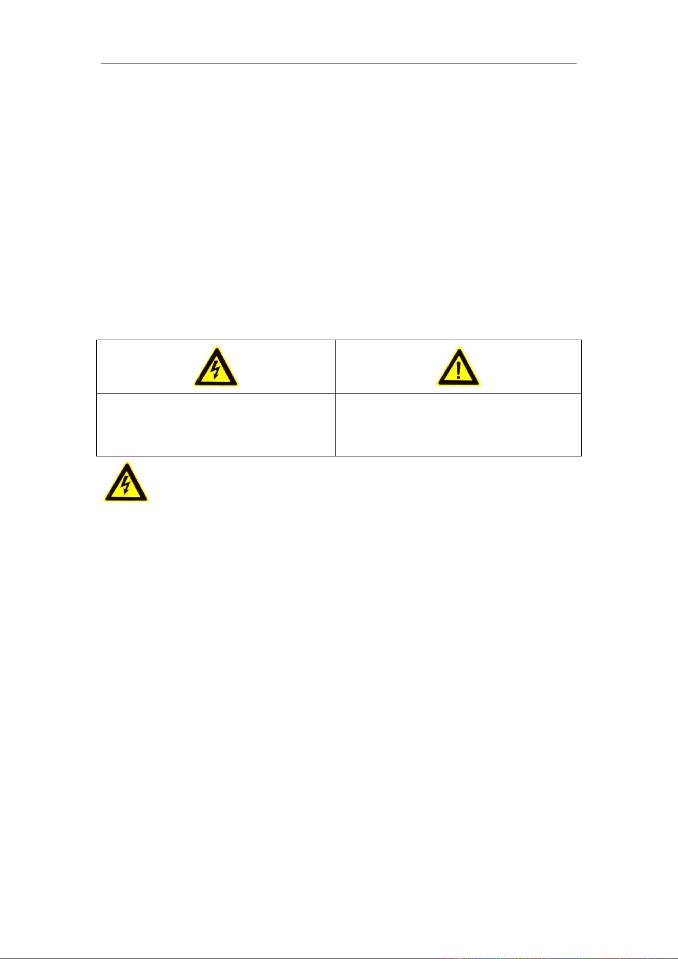
Warnings Follow these safeguards to
prevent serious injury or death.
Cautions Follow these precautions to
prevent potential injury or material
damage.
Warnings:
Please adopt the power adapter which can meet the safety extra low voltage
(SELV) standard. And source with 12 VDC according to the IEC60950-1 and
Limited Power Source standard.
To reduce the risk of fire or electrical shock, do not expose this product to rain or
moisture.
This installation should be made by a qualified service person and should conform
to all the local codes.
Please install blackouts equipment into the power supply circuit for convenient
supply interruption.
Please make sure that the ceiling can support more than 50(N) Newton gravities if
the camera is fixed to the ceiling.
If the product does not work properly, please contact your dealer or the nearest
service center. Never attempt to disassemble the camera yourself. (We shall not

User Manual of Video Vehicle Detector
5
assume any responsibility for problems caused by unauthorized repair or
maintenance.)
Cautions:
Make sure the power supply voltage is correct before using the camera.
Do not drop the camera or subject it to physical shock.
Do not touch sensor modules with fingers. If cleaning is necessary, use a clean
cloth with a bit of ethanol and wipe it gently. If the camera will not be used for an
extended period of time, put on the lens cap to protect the sensor from dirt.
Do not aim the camera lens at the strong light such as sun or incandescent lamp.
The strong light can cause fatal damage to the camera.
The sensor may be burned out by a laser beam, so when any laser equipment is
being used, make sure that the surface of the sensor not be exposed to the laser
beam.
Do not place the camera in extremely hot, cold temperatures (the operating
temperature should be between -30°C ~ 70°C), dusty or damp environment, and
do not expose it to high electromagnetic radiation.
To avoid heat accumulation, good ventilation is required for a proper operating
environment.
Keep the camera away from water and any liquid.
While shipping, the camera should be packed in its original packing.
Improper use or replacement of the battery may result in hazard of explosion.
Please use the manufacturer recommended battery type.

User Manual of Video Vehicle Detector
6
Table of Contents
Chapter 1 System Requirement ................................................................................ 8
Chapter 2 Network Connection ................................................................................ 9
2.1 Wiring over the LAN......................................................................................... 9
2.2 Activating the Camera .................................................................................... 10
2.2.1 Activation via Web Browser ............................................................................................ 10
2.2.2 Activation via SADP Software.......................................................................................... 11
2.3 Modifying the IP Address ............................................................................... 12
Chapter 3 Access to the Video Vehicle Detector .................................................... 14
Chapter 4 Live View................................................................................................. 16
4.1 Live View Page ............................................................................................... 16
4.2 Starting Live View .......................................................................................... 17
4.3 Recording and Capturing Pictures Manually .................................................... 17
4.4 Checking Live Traffic Statistics ........................................................................ 17
Chapter 5 Picture Search ........................................................................................ 21
Chapter 6 Log Search .............................................................................................. 22
Chapter 7 Local Configuration ............................................................................... 23
Chapter 8 System Configuration ............................................................................ 25
8.1 Device Information ........................................................................................ 25
8.2 Configuring Serial Ports .................................................................................. 26
8.3 Configuring TCP/IP Settings ............................................................................ 26
8.4 Port Settings .................................................................................................. 28
8.5 DDNS Settings ................................................................................................ 28
8.6 Time Configuration ........................................................................................ 29
8.7 Service ........................................................................................................... 31
Chapter 9 Encoding and Storage ............................................................................ 32
9.1 Video Encoding .............................................................................................. 32
9.2 ROI Settings ................................................................................................... 33
9.3 Storage Management ..................................................................................... 35
Chapter 10 Text Overlay ........................................................................................... 36
10.1 OSD Setting .................................................................................................... 36
Chapter 11 Capture Parameters ............................................................................... 38

User Manual of Video Vehicle Detector
7
11.1 Flash Light Parameters ................................................................................... 38
11.2 Traffic Light Synchronization ........................................................................... 39
Chapter 12 Image Parameters .................................................................................. 40
12.1 General Parameters ....................................................................................... 40
12.2 Video ............................................................................................................ 41
12.3 ICR................................................................................................................. 42
Chapter 13 Application Mode ................................................................................... 43
13.1 Application Mode .......................................................................................... 43
Chapter 14 Exception ................................................................................................ 45
Chapter 15 Maintenance ........................................................................................... 46
15.1 Checking Device Status ................................................................................... 46
15.2 Managing Users ............................................................................................. 46
15.3 Rebooting the Camera .................................................................................... 49
15.4 Resetting the Camera ..................................................................................... 49
15.5 Exporting/Importing Configuration File .......................................................... 49
15.6 Upgrading the System .................................................................................... 51
Appendix 52
Appendix 1 SADP Software Introduction ................................................................. 52

User Manual of Video Vehicle Detector
8
Chapter 1 System Requirement
Operating System: Microsoft Windows XP SP1 and above version / Vista / Win7 /
Server 2003 / Server 2008 32bits
CPU: 1.0 GHz or higher
RAM: 1G or higher
Display: 1024×768 resolution or higher
Web Browser: Internet Explorer 8.0 and above version, Apple Safari 5.0.2 and above
version, Mozilla Firefox 5.0 and above version and Google Chrome 18 and above
version.

User Manual of Network Traffic Camera
9
Chapter 2 Network Connection
Note:
You shall acknowledge that the use of the product with Internet access might be
under network security risks. For avoidance of any network attacks and
information leakage, please strengthen your own protection. If the product does
not work properly, please contact with your dealer or the nearest service center.
To ensure the network security of the camera, we recommend you to have the
camera assessed and maintained termly. You can contact us if you need such
service.
Purpose:
To view and configure the camera via a LAN, you need to connect the camera in the
same subnet with your computer, and install the SADP to search and change the IP of
the camera.
Note: For the detailed introduction of SADP, please refer to Appendix 1.
2.1 Wiring over the LAN
The following figures show the two ways of cable connection of a camera and a
computer:
Purpose:
To test the camera, you can directly connect the camera to the computer with a
network cable as shown in Figure 2-1.
Refer to the Figure 2-2 to set camera over the LAN via a switch or a router.
Network Cable
Computer
Traffic Camera
Figure 2-1 Connecting Directly
User Manual of Video Vehicle Detector
10
Network Cable
Network Cable
Switch
ComputerTraffic Camera
Figure 2-2 Connecting via a Switch or a Router
2.2 Activating the Camera
You are required to activate the camera first by setting a strong password for it before
you can use the camera.
Activation via Web Browser and Activation via SADP Software are supported.
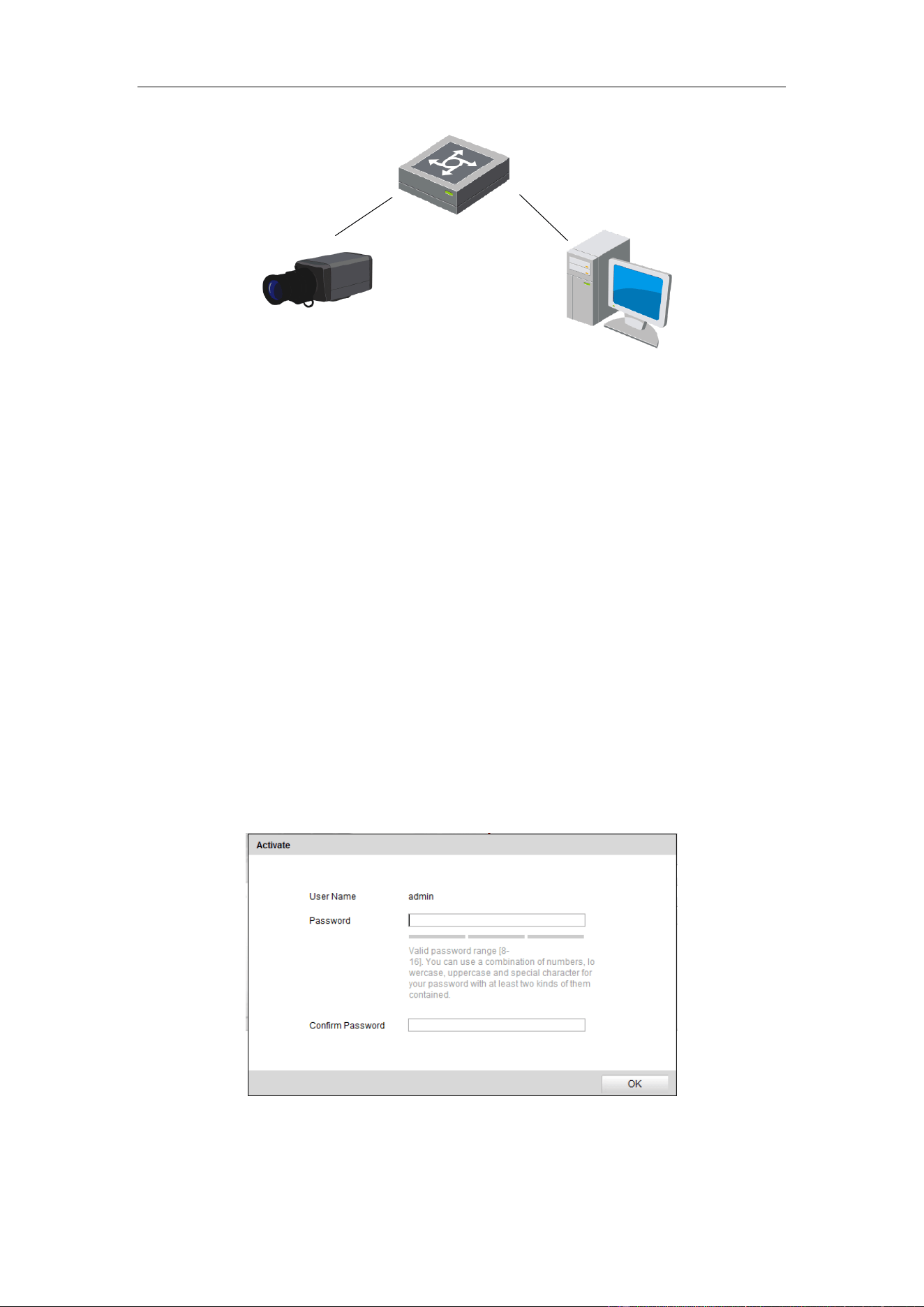
2.2.1 Activation via Web Browser
Steps:
1. Power on the camera, and connect the camera to the network.
2. Input the IP address into the address bar of the web browser, and press Enter to
enter the activation interface.
Note: The default IP address of the camera is 192.0.0.64.
Figure 2-3 Activation Interface (Web)
3. Create a password and input the password into the password field.
User Manual of Video Vehicle Detector
11
STRONG PASSWORD RECOMMENDED– We highly recommend
you create a strong password of your own choosing (using a minimum of
8 characters, including upper case letters, lower case letters, numbers,
and special characters) in order to increase the security of your product.
And we recommend you reset your password regularly, especially in the
high security system, resetting the password monthly or weekly can better
protect your product.
4. Confirm the password.
5. Click OK to save the password and enter the live view interface.
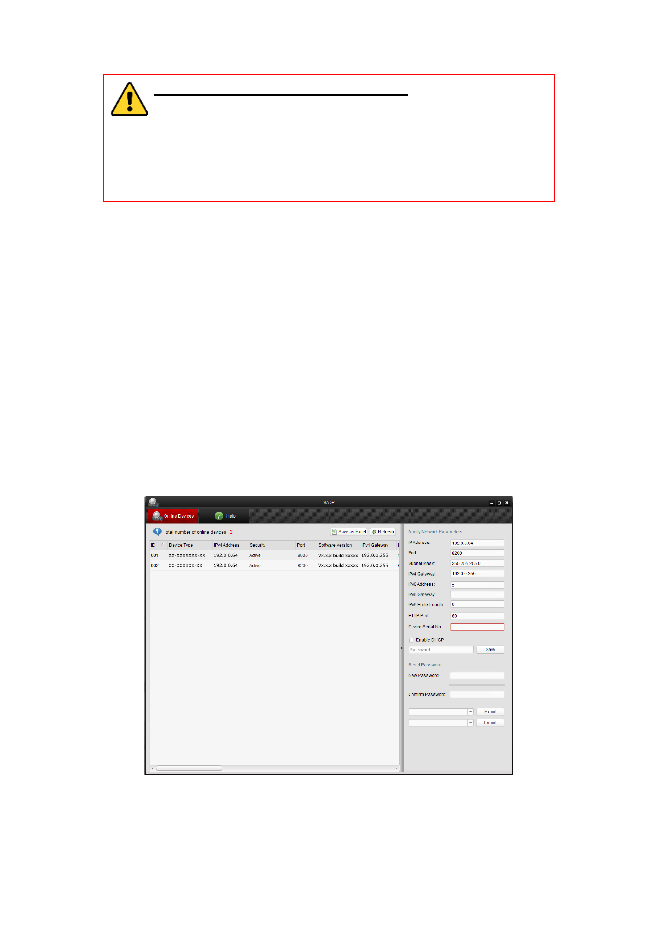
2.2.2 Activation via SADP Software
SADP software is used for detecting the online device, activating the camera, and
resetting the password.
Get the SADP software from the supplied disk or the official website, and install the
SADP according to the prompts.
Steps:
1. Run the SADP software to search the online devices.
2. Check the device status from the device list, and select the inactive device.
Figure 2-4 SADP Interface
Note: The SADP software supports activating the camera in batch. Please refer to
User Manual of Video Vehicle Detector
12
the user manual of SADP software for details.
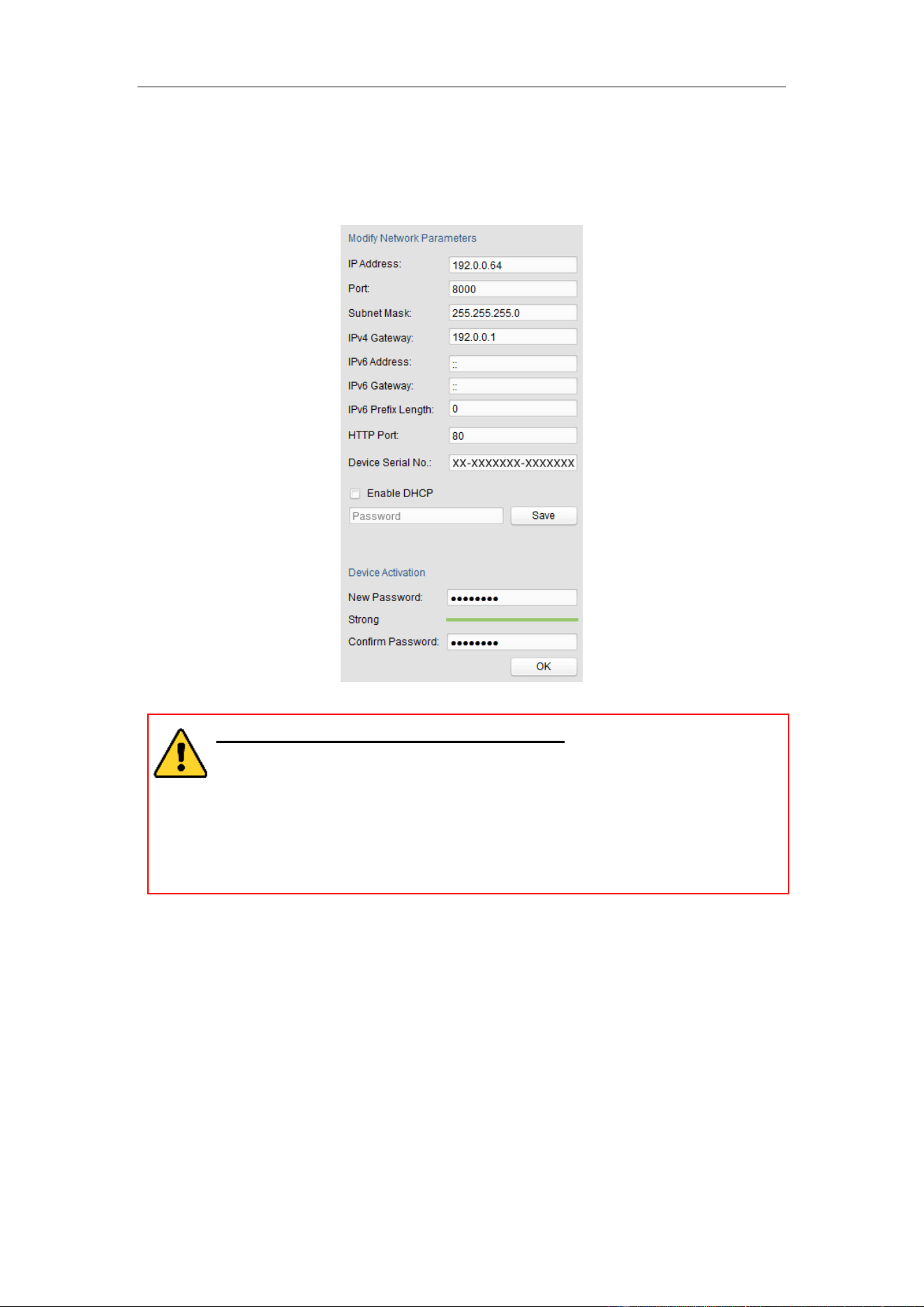
3. Create a password and input the password in the password field, and confirm the
password.
Figure 2-5 Create Password
STRONG PASSWORD RECOMMENDED– We highly recommend you
create a strong password of your own choosing (using a minimum of 8
characters, including upper case letters, lower case letters, numbers, and
special characters) in order to increase the security of your product. And
we recommend you reset your password regularly, especially in the high
security system, resetting the password monthly or weekly can better
protect your product.
4. Click OK to save the password.
You can check whether the activation is completed on the popup window. If
activation failed, please make sure that the password meets the requirement and
try again.
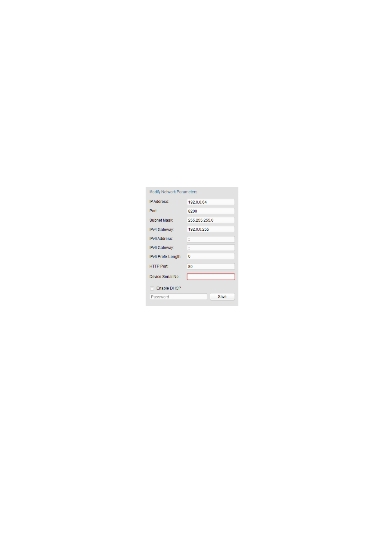
2.3 Modifying the IP Address
Purpose:
To view and configure the camera via LAN (Local Area Network), you need to
User Manual of Video Vehicle Detector
13
connect the camera in the same subnet with your PC. Then, install the SADP software
to search and change the IP of camera. We will take modifying the IP Address via
SADP software as an example to introduce the IP address modification.
Steps:
1. Run the SADP software.
2. Select an active device.
Note: Please refer to Chapter 2.2 to activate the camera if the camera is inactive.
3. Change the device IP address to the same subnet with your computer by
modifying the IP address manually.
Figure 2-6 Modify the IP Address
4. Input the password to activate your IP address modification.
The batch IP address modification is supported by the SADP; please refer to the
User Manual of SADP for details.
User Manual of Network Traffic Camera
14
Chapter 3 Access to the Video
Vehicle Detector
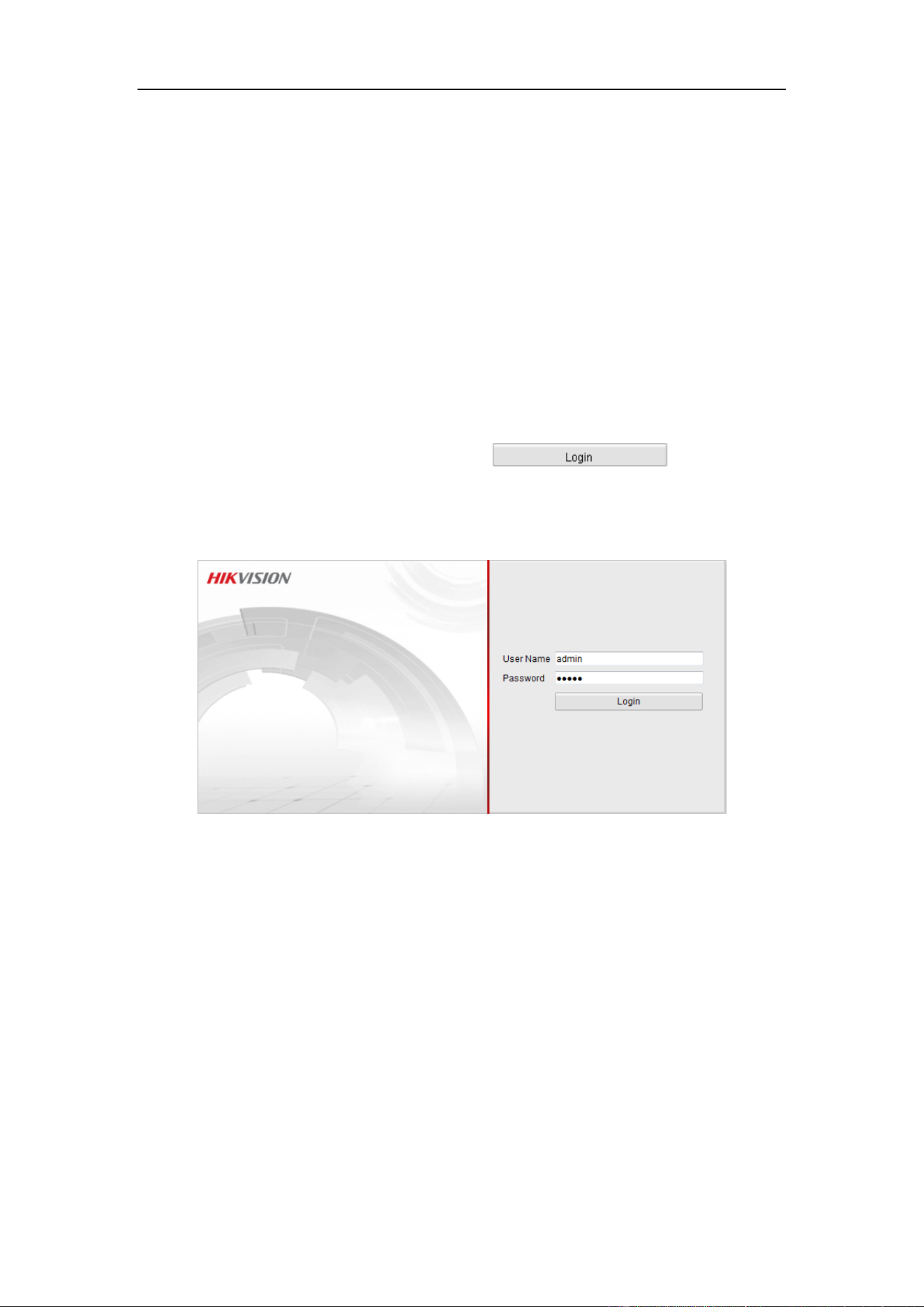
Steps:
1. Open the web browser.
2. In the browser address bar, input the IP address of the camera, and press the Enter
key to enter the login interface.
Note:
The default IP address is 192.0.0.64.
3. Input the user name and password and click .
The admin user should configure the device accounts and user/operator permissions
properly. Delete the unnecessary accounts and user/operator permissions.
Figure 3-1 Login Interface
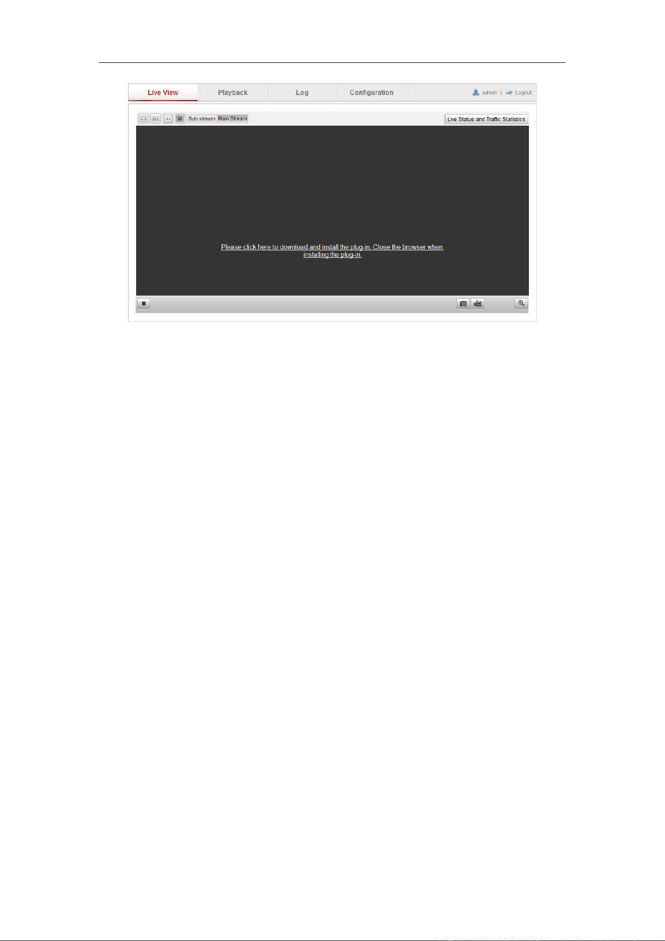
4. Install the plug-in before viewing the live video and operating the camera. Please
follow the installation prompts to install the plug-in.
User Manual of Video Vehicle Detector
15
Figure 3-2 Download and Install Plug-in
Note: You may have to close the web browser to install the plug-in. Please reopen
the web browser and log in again after installing the plug-in.
User Manual of Network Traffic Camera
16
Chapter 4 Live View
4.1 Live View Page
Purpose:
The live view page allows you to view the real-time video and capture images.
Log in the camera to enter the live view page, or you can click Live View on the
menu bar of the main page to enter the live view page.
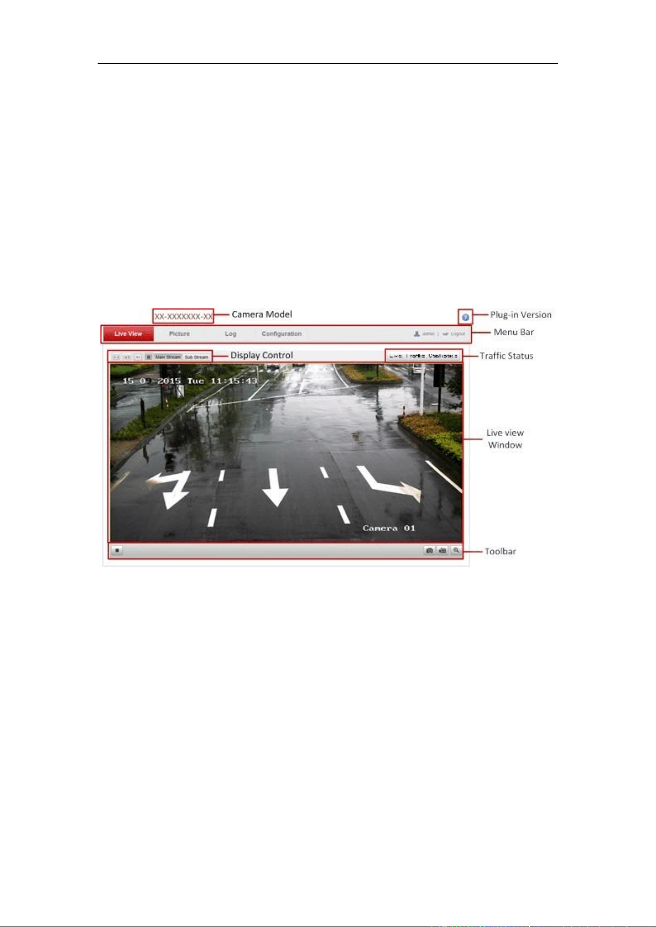
Descriptions of the live view page:
Figure 4-1 Live View Page
Menu Bar:
Click each tab to enter Live View, Picture, Log, and Configuration page respectively.
Display Control:
Click each tab to adjust the layout and the stream type of the live view.
Live View Window:
Display the live video.
Toolbar:
Operations on the live view page, e.g., start/stop live view, capture, record,
enable/disable digital zoom, etc.
User Manual of Video Vehicle Detector
17
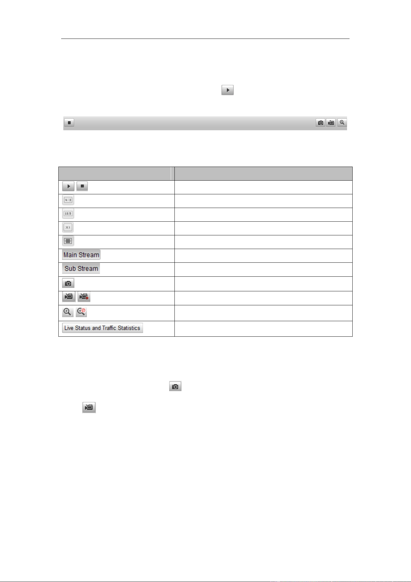
4.2 Starting Live View
In the live view window as shown below, click on the toolbar to start the live
view of the camera.
Figure 4-2 Live View Toolbar
Table 4-1 Descriptions of the Toolbar
Icon
Description
/
Start/Stop live view.
The window size is 4:3.
The window size is 16:9.
The original widow size.
Self-adaptive window size.
Live view with the main stream.
Live view with the sub stream.
Manually capture the picture.
/
Manually start/stop recording.
/
Turn on/off digital zoom function.
Enter the live status and traffic statistics interface
4.3 Recording and Capturing Pictures Manually
In the live view interface, click on the toolbar to capture the live pictures or
click to record the live view. The saving paths of the captured pictures and
recorded videos can be set on the Configuration > Local Configuration page.
Note: The captured image will be saved as JPEG file in your computer.
4.4 Checking Live Traffic Statistics
Click Live Traffic Statistics on the upper right of the live view window to enter the
live traffic statistics configuration interface.
User Manual of Video Vehicle Detector
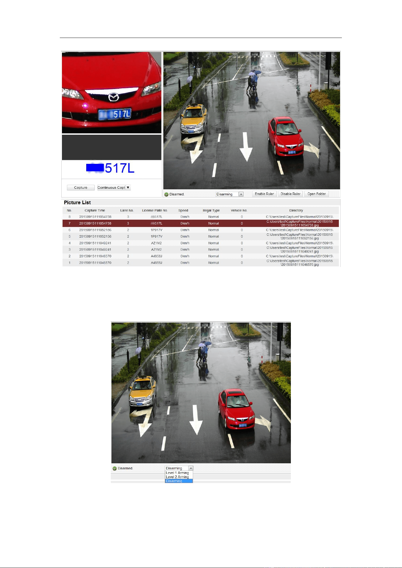
18
Figure 4-3 Live Status and Traffic Statistics Interface
As displayed on the figure above, the picture area can be divided into three parts:
scene shot area, digital zoom area, license plate area.
Figure 4-4 Scene Shot
Arm the camera: Level 1 Arming, Level 2 Arming, and disarming are selectable.
User Manual of Video Vehicle Detector
19
Level 1 Arming: The camera is allowed to connect to only one data storage
device for image and information uploading. It is recommended when you
develop products, that is, if you use SDK, level 1 arming is the only option.
Level 2 Arming: The camera is allowed to connect to three data storage
devices for image and information uploading.
Note: Level 2 Arming is recommended for debugging. Because when the
device is running, Level 1 Arming cannot be activated.
Open Folder: Open the folder that saves the captured pictures.
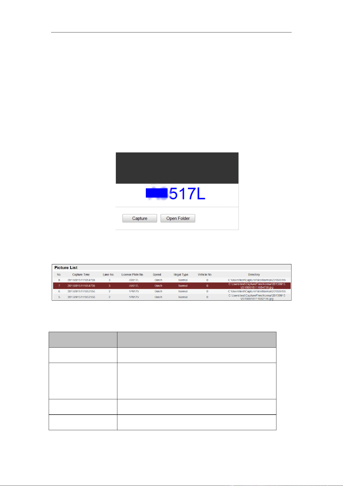
Figure 4-5 Plate Area
Capture: Click Capture to capture the image.
Figure 4-6 Picture List
Table 4-2 Description
Item
Description
No.
Picture No.
Capture Time
The time of capturing the picture with millisecond
precision. For example, 20150915111054738 means
the picture is captured at 11:10:54:738, on September
15
th
, in 2015.
Lane No.
The lane where the vehicle is captured.
License Plate No.
The license plate number of the vehicle.

User Manual of Video Vehicle Detector
20
Speed
The speed of the captured vehicle.
Illegal Type
The captured type, normal, over speed, wrong
direction are selectable.
Vehicle No.
The vechile counting No., ranges from 1 to 65535,
overwrites if it reachs the max. value.
Directory
The file path of the saved picture.
User Manual of Network Traffic Camera
21
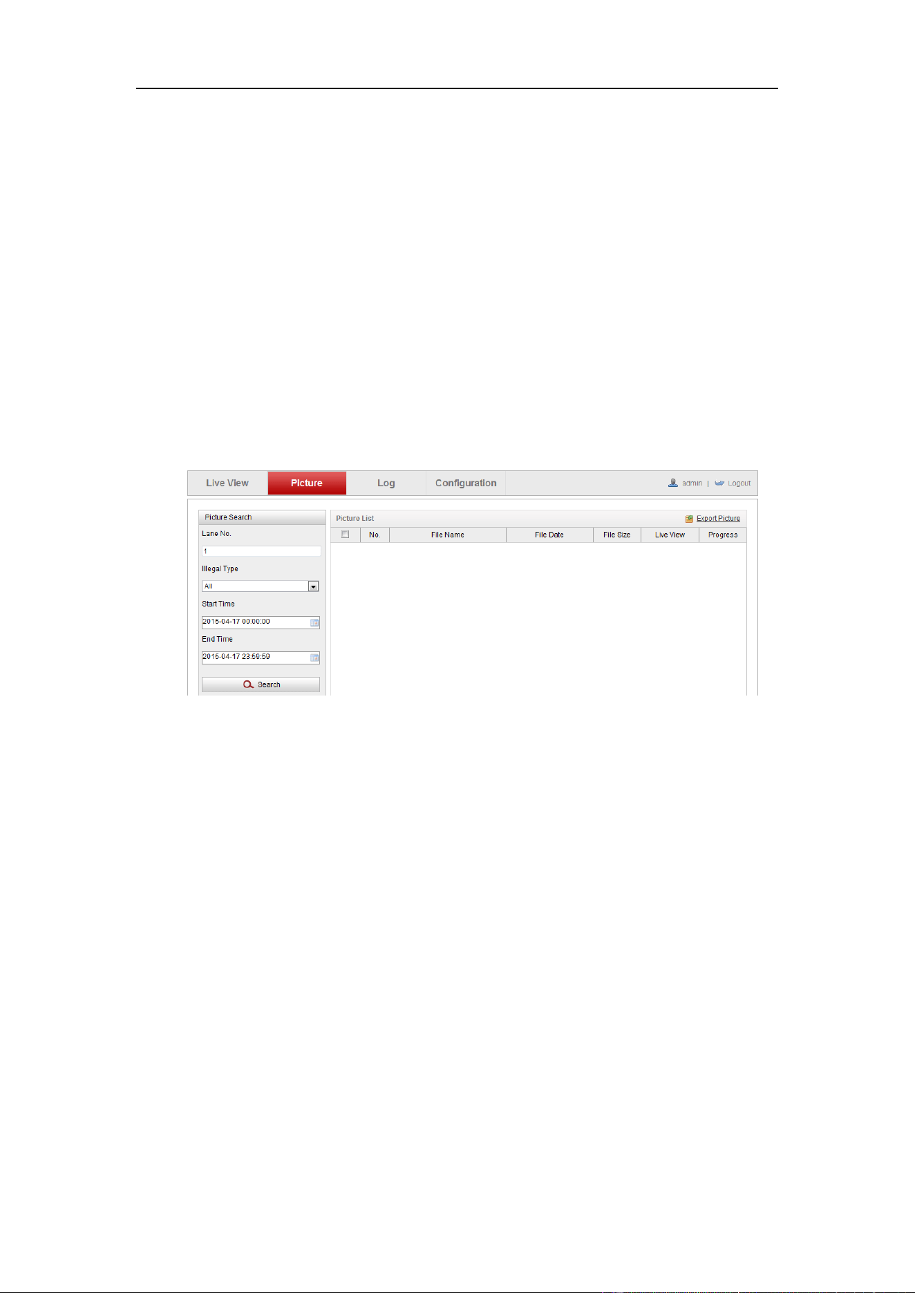
Chapter 5 Picture Search
Purpose:
The captured picture of all types, including normal, overspeed, reverse driving, etc.,
can be searched from this page. You can also export the pictures to the PC local
directory.
Before you start:
Please insert a SD card in the camera for picture storage.
Steps:
1. Click Picture on the menu bar to enter picture searching interface.
Figure 5-1 Picture Searching Interface
2. Set the picture search conditions to specify the search, including the Lane No.,
Illegal Type, Start Time and End Time.
3. Click Search to search pictures. The matched pictures will be displayed on the
Picture List interface.
4. Click Export Picture to export the pictures in your computer.
User Manual of Network Traffic Camera
22
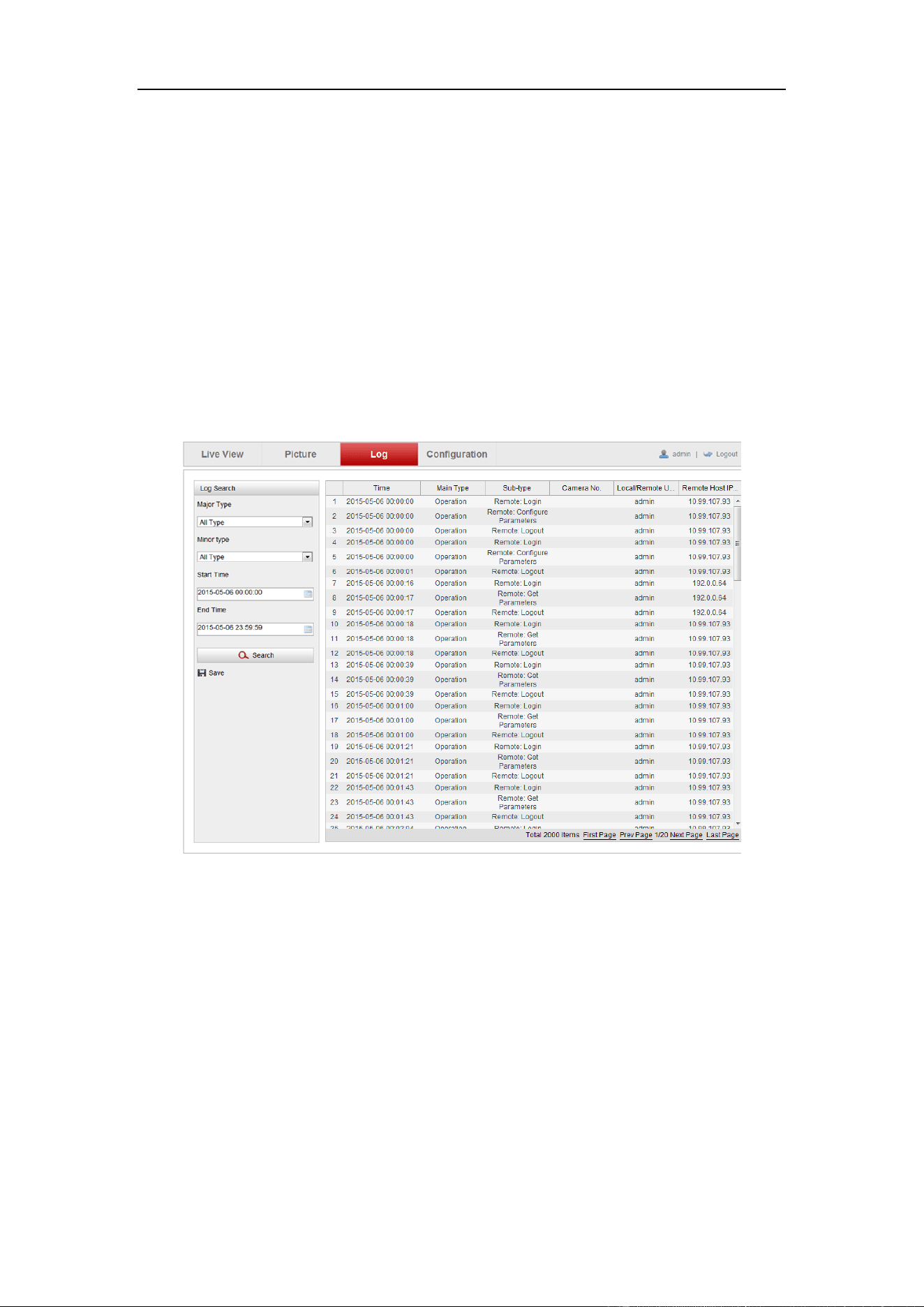
Chapter 6 Log Search
Purpose:
The operation, alarm, exception and information of the camera can be stored in log
files. You can also export the log files on your demand.
Before you start:
Please configure network storage for the camera or insert a SD card in the camera.
Steps:
1. Click Log on the menu bar to enter log searching interface.
Figure 6-1 Log Searching Interface
2. Set the log search conditions to specify the search, including the Major Type,
Minor Type, Start Time and End Time.
3. Click Search to search log files. The matched log files will be displayed on the
Log interface.
4. To export the log files, click Save to save the log files in your computer.
User Manual of Network Traffic Camera
23
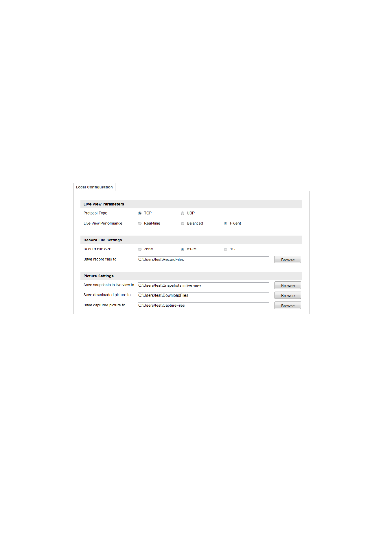
Chapter 7 Local Configuration
Purpose:
You can configure the live view parameters, recording files settings, and picture
settings from this page.
Note:
The record files and captured pictures are the ones you record and captured using the
web browser and thus the saving paths of them are on the PC running the browser.
Enter the local configuration interface: Configuration > Local Configuration.
Figure 7-1 Local Configuration
Steps:
1. Configure the following settings:
Live View Parameters: Set the protocol type and live view performance.
Protocol Type: TCP and UDP are selectable.
TCP: Ensures complete delivery of streaming data and better video quality,
yet the real-time transmission will be affected.
UDP: Provides real-time audio and video streams.
Live View Performance: Set the live view performance to Real-time, Balanced
or Fluent.
Save record files to: Set the manual recorded video parameters.
Record File Size: Select the packed size of the manually recorded and

User Manual of Video Vehicle Detector
24
downloaded video files to 256M, 512M or 1G. After the selection, the maximum
record file size is the value you selected.
Save record files to: Set the saving path for the manually recorded video files in
the live view page.
Picture Settings: Set the saving path of pictures under the different conditions.
Save snapshots in live view to: Set the saving path of the manually captured
pictures in live view.
Save downloaded pictures to: Set the saving path of the captured pictures in
picture search interface.
Save captured pictures to: Set the saving path of the captured pictures in the
live status and traffic statistic interface.
Note: You can click Browse to change the directory for saving the videos and
pictures.
2. Click Save to save the settings.
User Manual of Network Traffic Camera
25
Chapter 8 System Configuration
Purpose:
You can configure the parameters on this page, including device information, serial
ports, network parameters, time configuration, service, etc..
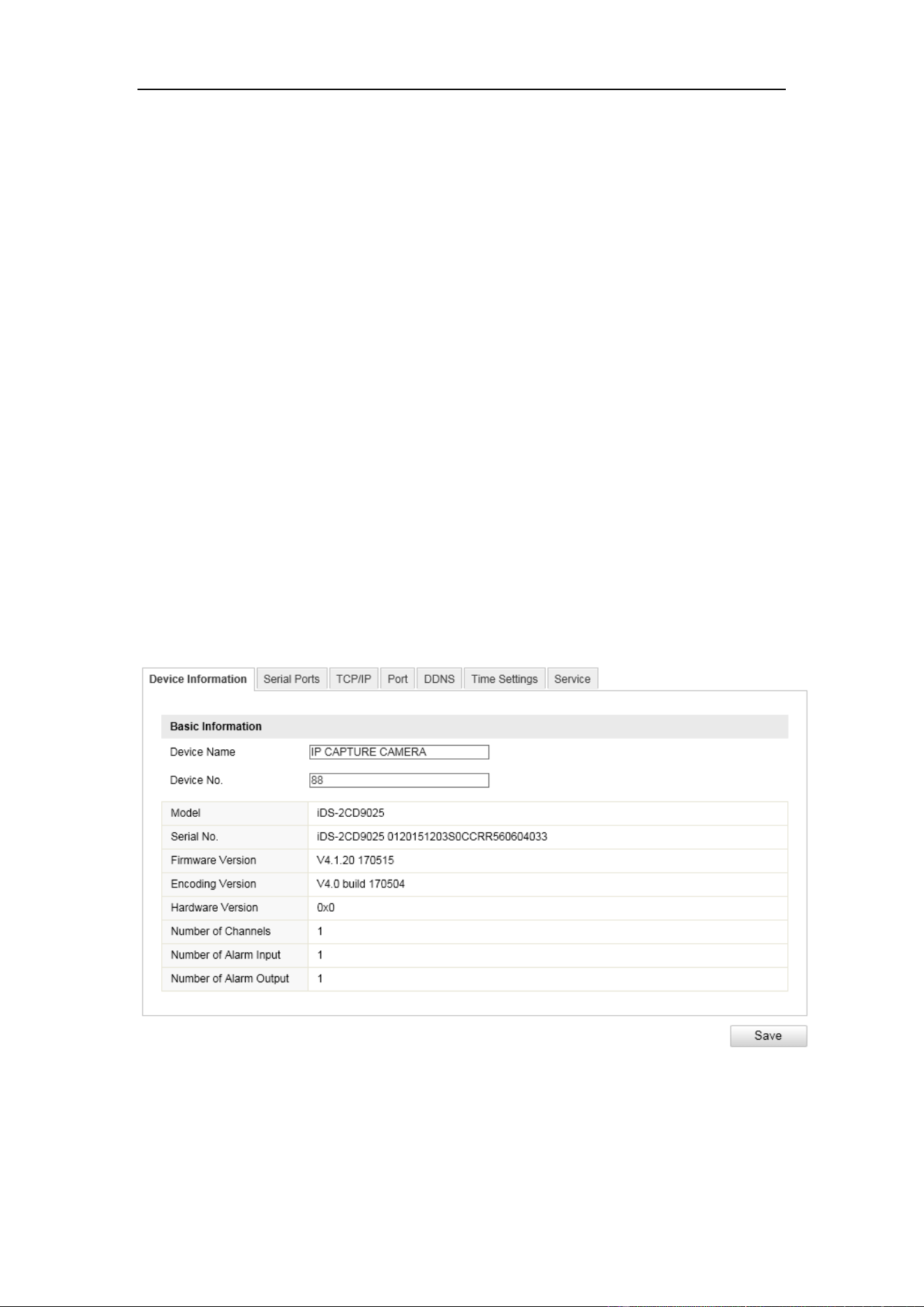
8.1 Device Information
Go to the device information interface to check the device information:
Configuration > Device Configuration > System Configuration > Device
Information
Device Name and Device No. can be changed as desired.
Other information of the camera, such as Model, Serial No., Firmware Version,
Encoding Version, Hardware Version, Camera No., Linkage Trigger Input, Linkage
Trigger Output are displayed for your reference. And those information cannot be
edited in this menu.
Figure 8-1 Device Information
User Manual of Video Vehicle Detector
26
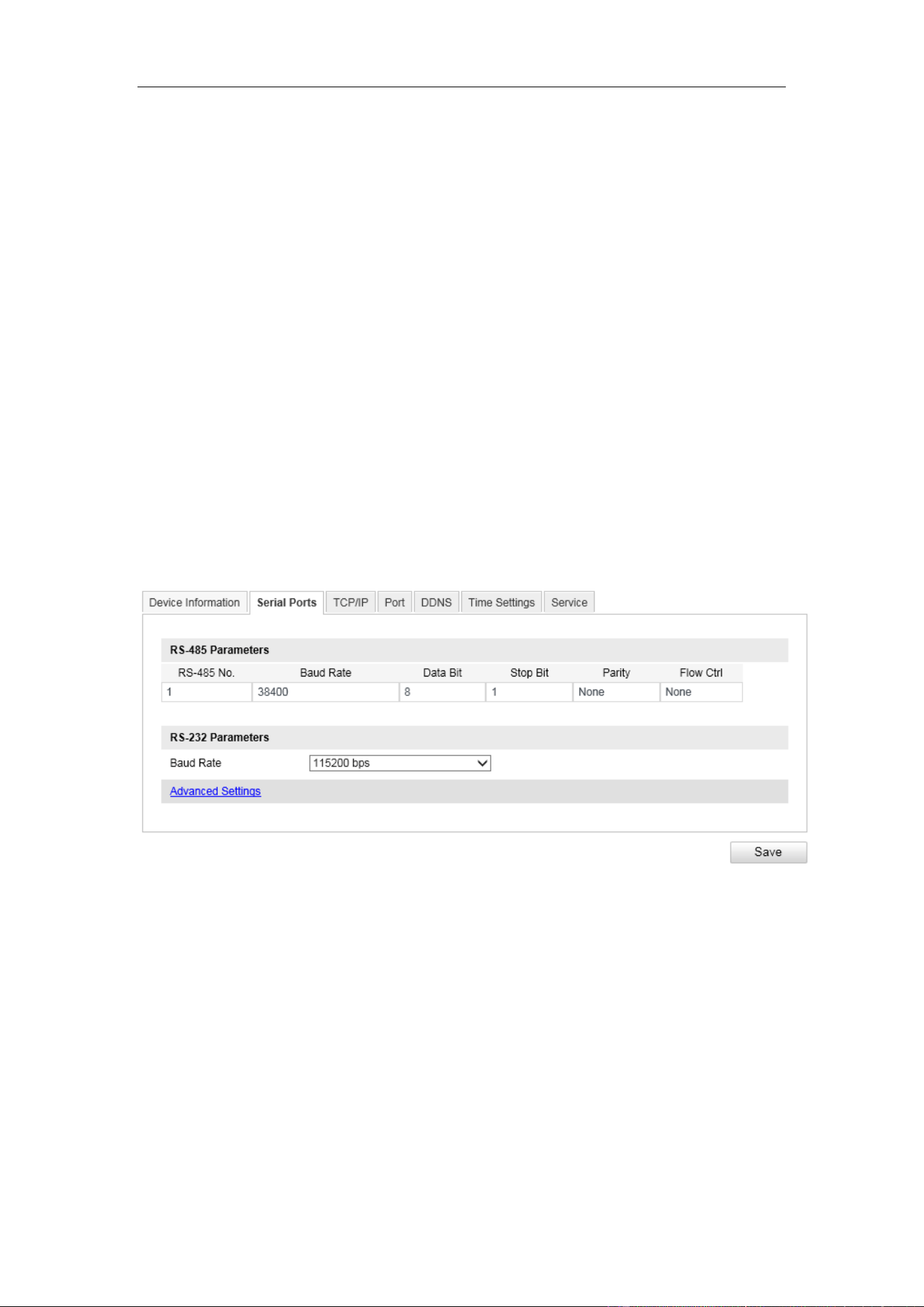
8.2 Configuring Serial Ports
Configure the RS-485 parameters and RS-232 parameters in this page.
The RS485 ports are used to input signals related to traffic control. The number
of available RS485 ports can be different according to different camera models.
The RS-232 port can be used in two ways:
• Parameters Configuration: Connect a computer to the camera through the
serial port. Device parameters can be configured by using software such as
HyperTerminal. The serial port parameters must be the same as the serial port
parameters of the camera.
• Transparent Channel: Connect a serial device directly to the camera. The
serial device will be controlled remotely by the computer through the
network.
Figure 8-2 Serial Port Parameters
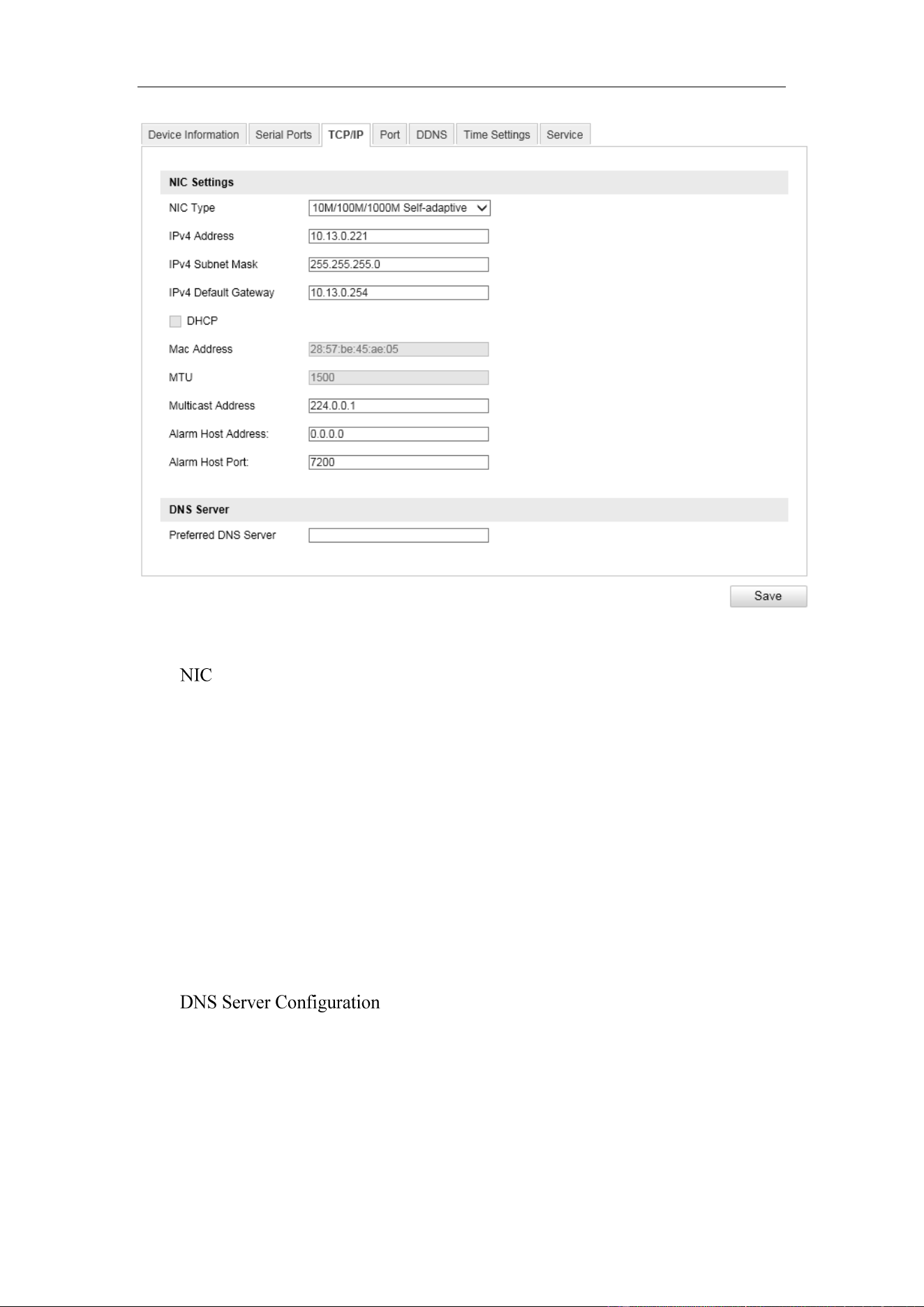
8.3 Configuring TCP/IP Settings
Purpose:
TCP/IP settings must be properly configured before you operate the camera over
network.
User Manual of Video Vehicle Detector
27
Figure 8-3 Network Parameters
Settings
Configure the NIC parameters, including the NIC Type, IPv4 Address, IPv4 Subnet
Mask, IPv4 Default Gateway, MAC Address (read-only), MTU settings (read-only),
Multicast Address and Alarm Management Host Address/Port.
Notes:
The Multicast sends a stream to the multicast group address and allows multiple
clients to acquire the stream at the same time by requesting a copy from the multicast
group address. Before utilizing this function, you have to enable the Multicast
function of your router.
DNS (Domain Name System) is a network system used to translate names into IP
address.
User Manual of Video Vehicle Detector
28
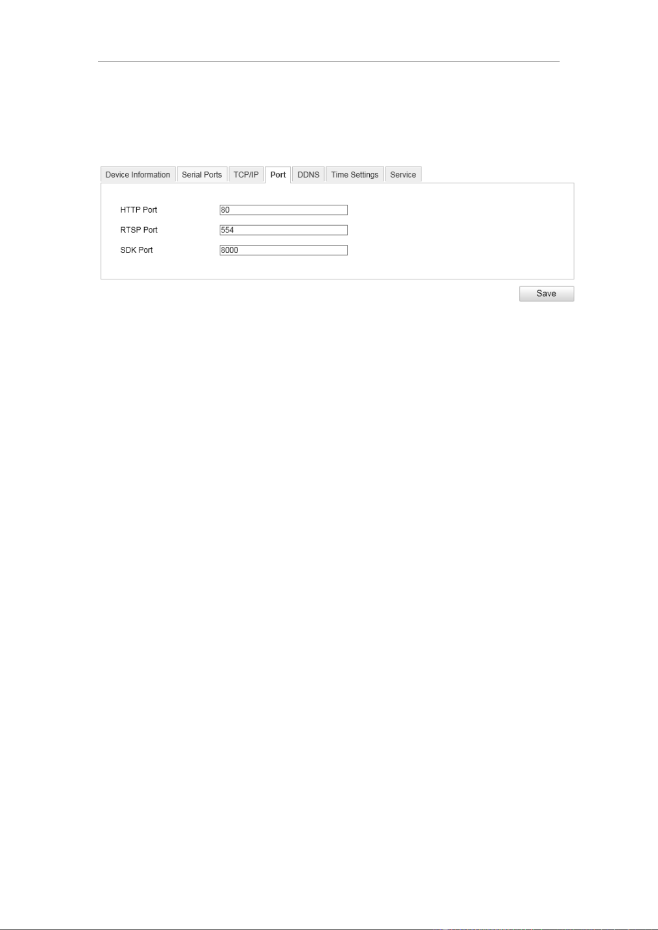
8.4 Port Settings
Configure the HTTP port, RTSP port, SDK port information on this page.
Figure 8-4 Port Configuration Interface
HTTP Port: The default port number is 80, and it can be changed to any port No.
ranges from 1 to 65536 which is not occupied, except 21(FTP port) and 23(Telnet
port).
RTSP Port: The default port number is 554 and it can be changed to any port No.
ranges from 1to 65536 which is not occupied, except 21(FTP port) and 23(Telnet
port).
SDK Port: The default server port number is 8000, and it can be changed to any
port No. ranges from 2000 to 65535 which is not occupied.
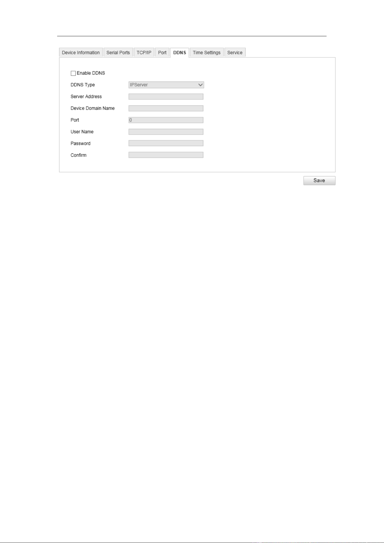
8.5 DDNS Settings
If your camera is set to use PPPoE as its default network connection, you can use the
Dynamic DNS (DDNS) for network access.
User Manual of Video Vehicle Detector
29
Figure 8-5 DDNS Settings
Steps:
1. Enter the DDNS Settings interface: Configuration > Device Configuration >
System Configuration > DDNS.
2. Check the Enable DDNS checkbox to enable this feature.
3. Enter the Server Address of the IP Server.
4. Click Save to save the settings.
Note: For the IPServer DDNS, you have to apply a static IP, subnet mask, gateway
and preferred DNS from the ISP. The Server Address should be entered with the
static IP address of the computer that runs the IP Server software.
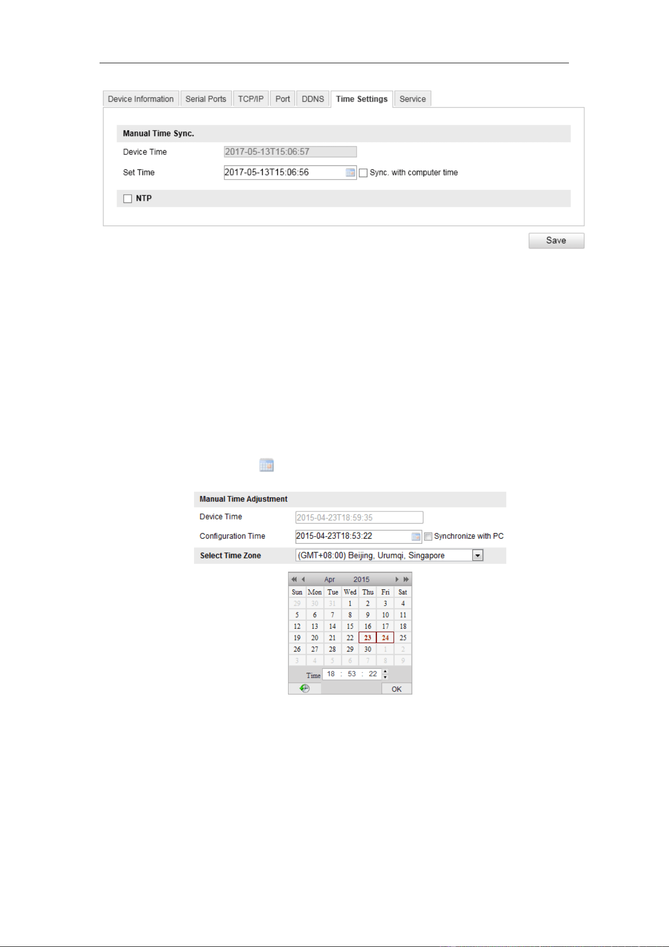
8.6 Time Configuration
You can follow the instructions in this section to configure the time synchronization
and DST settings.
Time Setting
Steps:
1. Enter the Time Settings interface: Configuration > Device Configuration >
System Configuration> Time Configuration
User Manual of Video Vehicle Detector
30
Figure 8-6 Time Settings
2. Select the time zone of your region.
3. You can adjust time manually. Or you can enable NTP (National Time Protocol)
to synchronize time of your camera to the configured NTP server.
● Manual Time Adjustment
Steps:
1) Check the Device Time. The grayed out device time shows the current
camera time.
2) Click the time icon to set the system time from the pop-up calendar.
Figure 8-7 Time Sync Manually
3) (Optional) you can also check the checkbox of Synchronize with PC. The
camera time is synchronized with the time of your computer.
● Time Adjustment by NTP
Steps:
1. Check the checkbox of Enable NTP.
2. Configure the following settings:
User Manual of Video Vehicle Detector
31
Server Address: IP address of NTP server.
NTP Port: Port of NTP server.
Time Adjustment Interval: The time interval between the two
synchronizing actions with NTP server.
Note: If the camera is connected to a public network, you should use a NTP
server that has a time synchronization function, such as the server at the National
Time Center (IP Address: 210.72.145.44). If the camera is set in a customized
network, NTP software can be used to establish a NTP server for time
synchronization.
4. Click Save to save the settings.
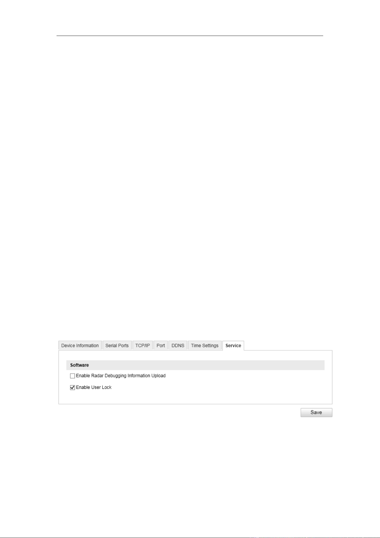
8.7 Service
User lock is a function that limits the failed login attempts, thus to secure the data
viewed, captured and recorded on the camera.
When the user lock function is enabled, the admin and operator users would be locked
for 30 minutes after 6 failed login attempts.
Figure 8-8 User Lock Setting
User Manual of Video Vehicle Detector
32
Chapter 9 Encoding and Storage
Purpose:
You can configure the encoding and storage related parameters from this page,
including video encoding, image encoding, ROI, redundant storage, network storage,
and cloud storage,
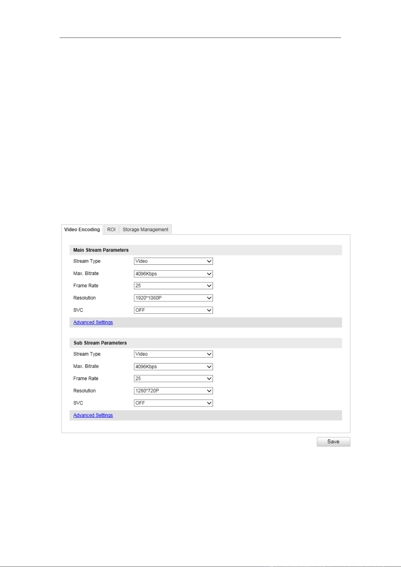
9.1 Video Encoding
Steps:
1. Enter the Video Encoding interface: Configuration >Device Configuration >
Encoding and Storage > Video Encoding
Figure 9-1 Video Settings
2. Configure the Main Stream Parameters:
The main stream is usually for recording and live viewing with good bandwidth.
Stream Type: The Video is supported currently.

User Manual of Video Vehicle Detector
33
Bitrate: Set the max. bitrate to 32 to16384 Kbps, or custom. The higher value
corresponds to the higher video quality, and the higher bandwidth is required.
Note: The maximum limit of the max. bitrate value varies according to different
cameras. For some certain cameras, the maximum limit is 8192Kbps or
12288Kbps.
Frame Rate: Set the frame rate to 1/16~25 fps. The frame rate is to describe the
frequency at which the video stream is updated and it is measured by frames per
second (fps). A higher frame rate is advantageous when there is movement in the
video stream, as it maintains image quality throughout.
Resolution: Select the resolution of the video output.
SVC: Scalable Video Coding is an extension of the H.264/AVC standard. Select
close/enable to disable/enable the SVC function.
Bitrate Type: Select the bitrate type to Constant or Variable.
Image Quality: When bitrate type is selected as Variable, 6 levels of video
quality are selectable from the dropdown list.
Profile: Basic profile, Main Profile and High Profile for coding are selectable.
I Frame Interval: The default I frame interval is 50. It is not configurable for
cameras of this series.
Video Encoding: H.264 and MJPEG are selectable for both main stream and sub
stream.
3. Configure the sub-stream parameters. Sub-stream can be used for live viewing
when the bandwidth is limited.
4. Click Save to save the settings.
9.2 ROI Settings
Purpose:
ROI (Region of Interest) encoding helps to discriminate the ROI and background
information in video compression, which means, the technology assigns more
encoding resource to the region of interest, thus to increase the quality of the ROI
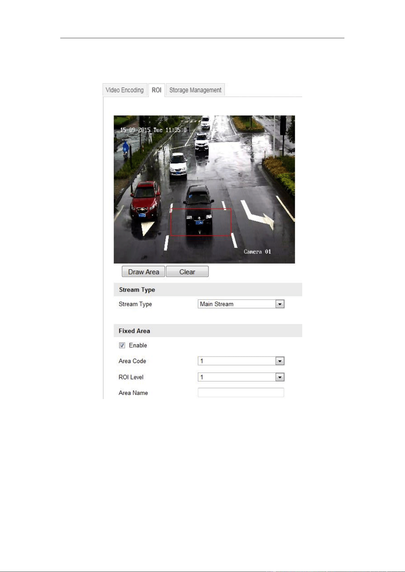
User Manual of Video Vehicle Detector
34
whereas the background information is less focused.
Note: ROI function varies according to different camera models.
Figure 9-2 ROI Settings
Steps:
1. Enter the ROI settings interface:
Configuration> Device Configuration> Encoding and Storage > ROI
2. Select the stream type for ROI encoding.
3. Select the region from the drop-down list for ROI settings. There are four fixed
regions selectable.
User Manual of Video Vehicle Detector
35
4. Click the Draw Area button, and then click-and-drag the mouse to draw the
region of interest on the live video.
5. Select the ROI level to set the image quality enhancing level. The larger the value
is, the better the image quality is.
6. Input the region name for ROI as desired.
7. Click Save to save the settings.
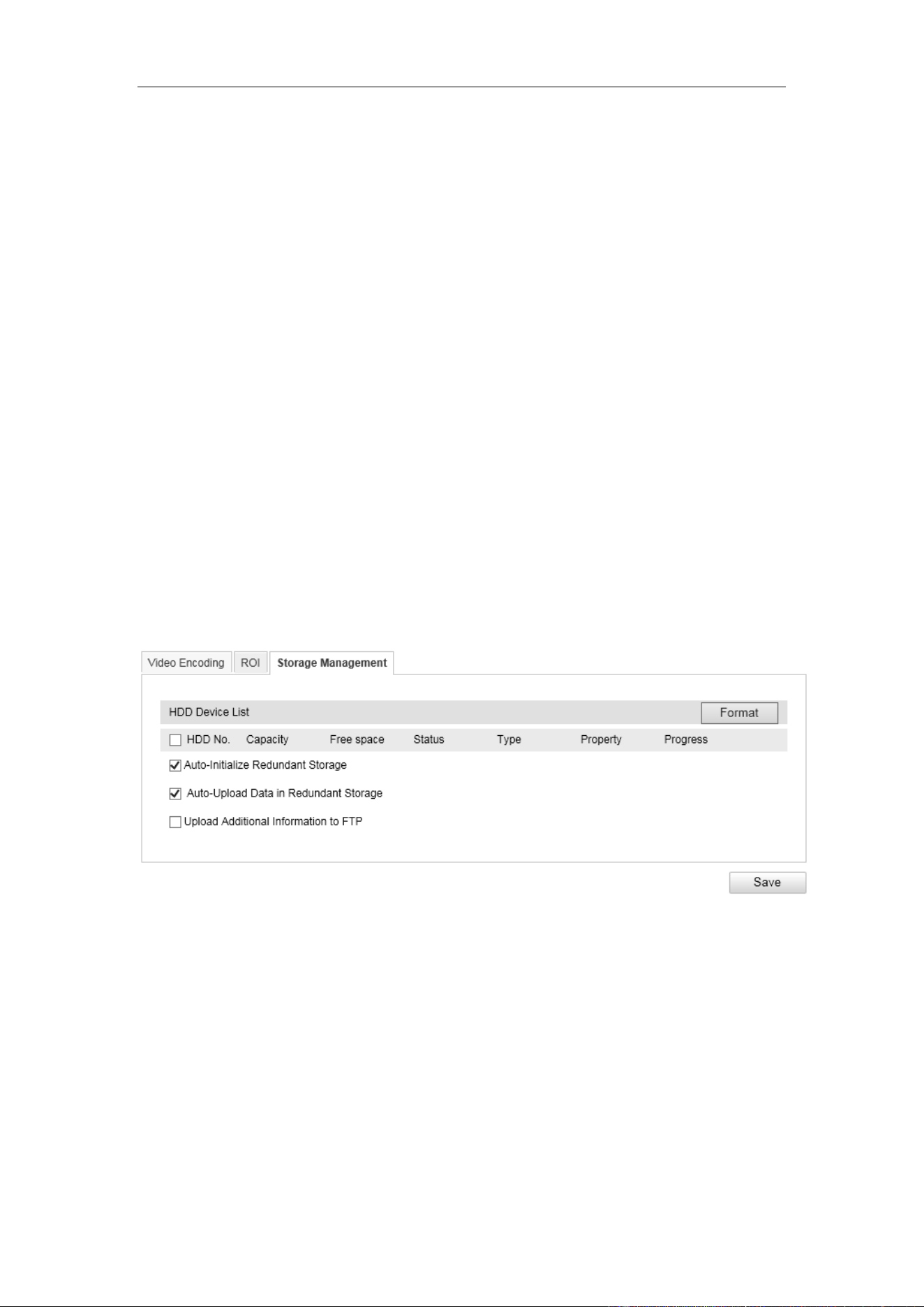
9.3 Storage Management
To configure record settings, please make sure that you have an SD card inserted in
your camera.
The local storage should be properly configured to store the recorded files, log files,
etc.
You can configure the FTP server related information to enable the uploading of the
captured pictures to the FTP server.
Figure 9-3 Storage Management Interface
User Manual of Video Vehicle Detector
36
Chapter 10 Text Overlay
Purpose:
Configure the OSD on the videos.
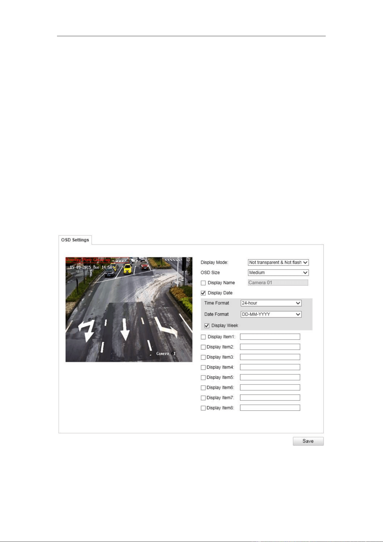
10.1 OSD Setting
Purpose:
You can customize the camera name, time format, and the additional information on
the screen.
Steps:
1. Enter the video text overlay configuration interface: Configuration > Device
Configuration > Text Overlay > OSD Setting.
Figure 10-1 OSD on Video
2. Set the OSD property and font size in the dropdown list as desired.
3. Check the corresponding checkbox to select the display of camera name, date,

User Manual of Video Vehicle Detector
37
week or additional display items if required.
4. Edit the camera name in the text field of Camera Name.
5. Select from the drop-down list to set the time format, date format.
6. You can use the mouse to click and drag the text frame in the live view window to
adjust the OSD position.
7. (Optional)Use the mouse to click and drag the red text frame in the live view
window to adjust the text overlay position.
8. Edit the Display Item in the text field Item1-Item8.
9. Click Save to activate the settings.
User Manual of Video Vehicle Detector
38
Chapter 11 Capture Parameters
Purpose:
You can configure the license plate parameters, flash light parameters, traffic light
synchronization, and image composition on this page.
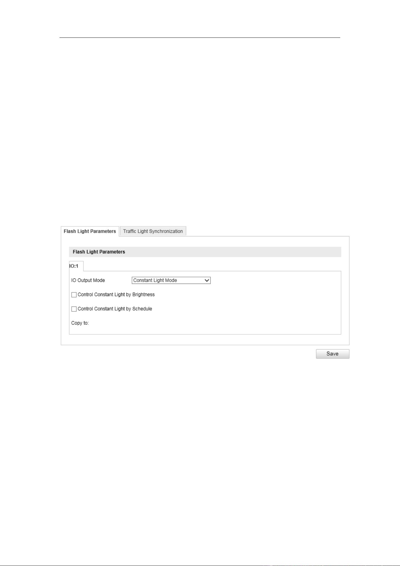
11.1 Flash Light Parameters
Steps:
1. Enter the flash light configuration interface. Configuration > Device
Configuration > Capture Parameters > Flash Light Parameters.
2. Select a tab corresponded with the flash light control port.
Figure 11-1 Flash Light Parameters
3. Check the checkbox to enable flash light, and select flash light plan according to
the actual environment.
Enable Constant Light according to Brightness Condition: Set the brightness
threshold from 0 to 100, and the flash light takes into effect when the brightness
comes to the threshold.
Enable Constant Light according to Time Schedule: Set the start time and the
end time. The flash light takes into effects according to the time schedule you
configured.
4. (Optional) You can copy the same settings to other channels by checking the
User Manual of Video Vehicle Detector
39
checkbox of channel number.
5. Click Save to activate the settings.
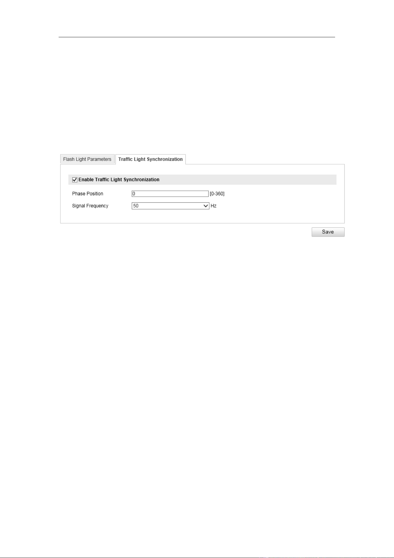
11.2 Traffic Light Synchronization
1. Enter the Traffic Light Synchronization: Configuration> Device
Configuration > Capture Parameters > Traffic Light Synchronization
Figure 11-2 Traffic Light Synchronization
2. Enable Traffic Light Synchronization.
3. Input Phase Position time.
4. Select the Signal Frequency.
5. Click Save to activate the settings.
User Manual of Video Vehicle Detector
40
Chapter 12 Image Parameters
Purpose:
Configure the general parameters, video image parameters, capture image parameters,
and ICR from this page.
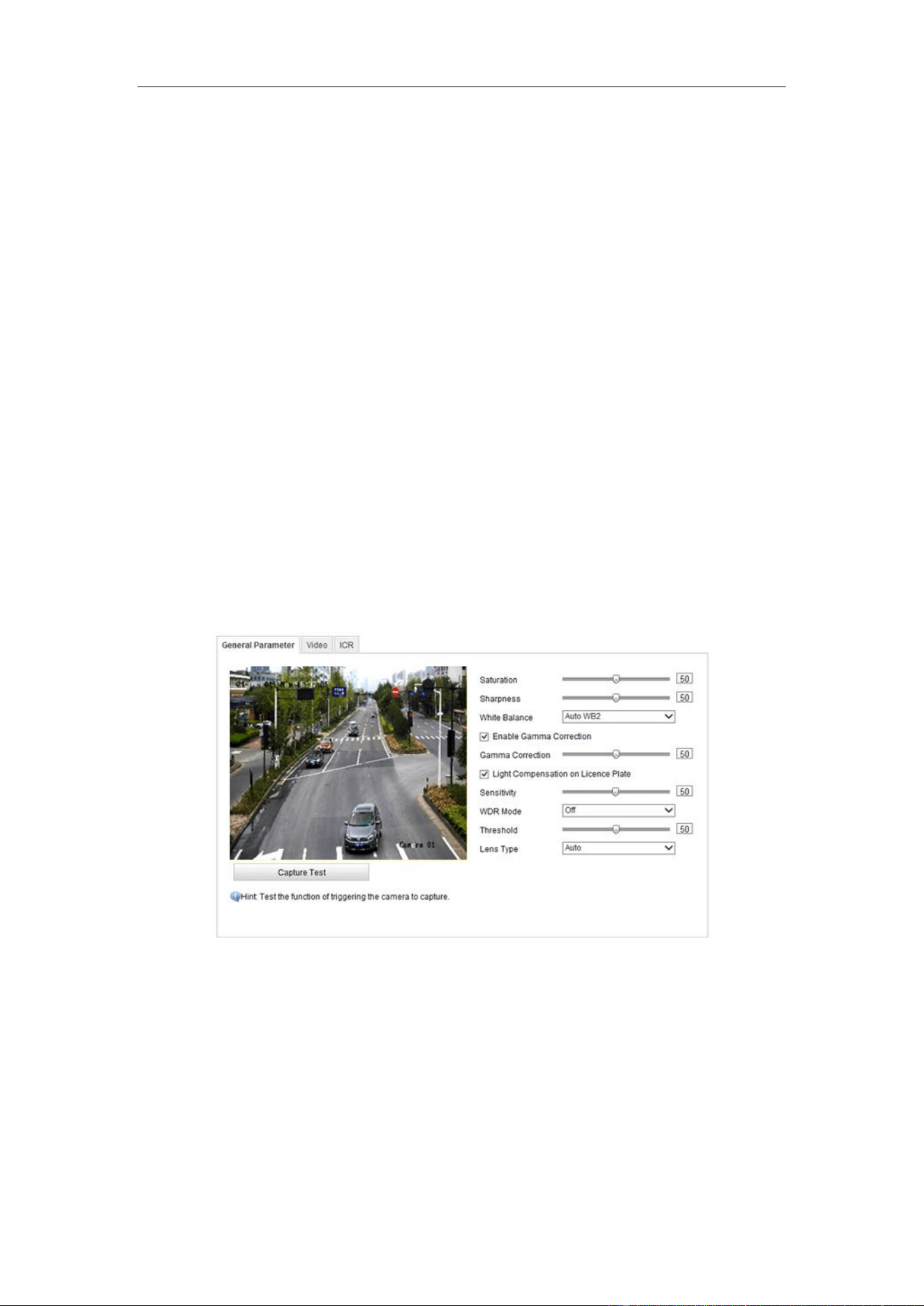
12.1 General Parameters
Purpose:
General parameters configure the image parameters apply to both video image and
capture image, including saturation, sensitivity, picture size, sharpness, white balance,
gamma correction and brightness enhancement.
Steps:
1. Enter the general parameters configuration interface: Configuration > Device
Configuration > Image Parameters > General Parameter.
Figure 12-1 General Parameters
2. Set the image saturation, sharpness and white balance mode.
Saturation describes the colorfulness of the image color, which ranges from
0 to 100.
Sharpness describes the edge contrast of the image, which ranges from 1 to
100.
White Balance is the white rendition function of the camera used to adjust
User Manual of Video Vehicle Detector
41
the color temperature according to the environment.
3. Input the JPEG picture size. The captured pictures are saved as JPEG files, and
you can define the picture size by manually input the value.
4. (Optional) Enable gamma correction by checking the checkbox. And adjust the
correction level from 0 to 100.
5. (Optional) Enable the light compensation on license plate by checking the
checkbox. Adjust the sensitivity to 0 to 100 if you enable the function.
6. You can click Capture Test to see the effects after you complete the adjustment.
7. Click Save to activate the settings.
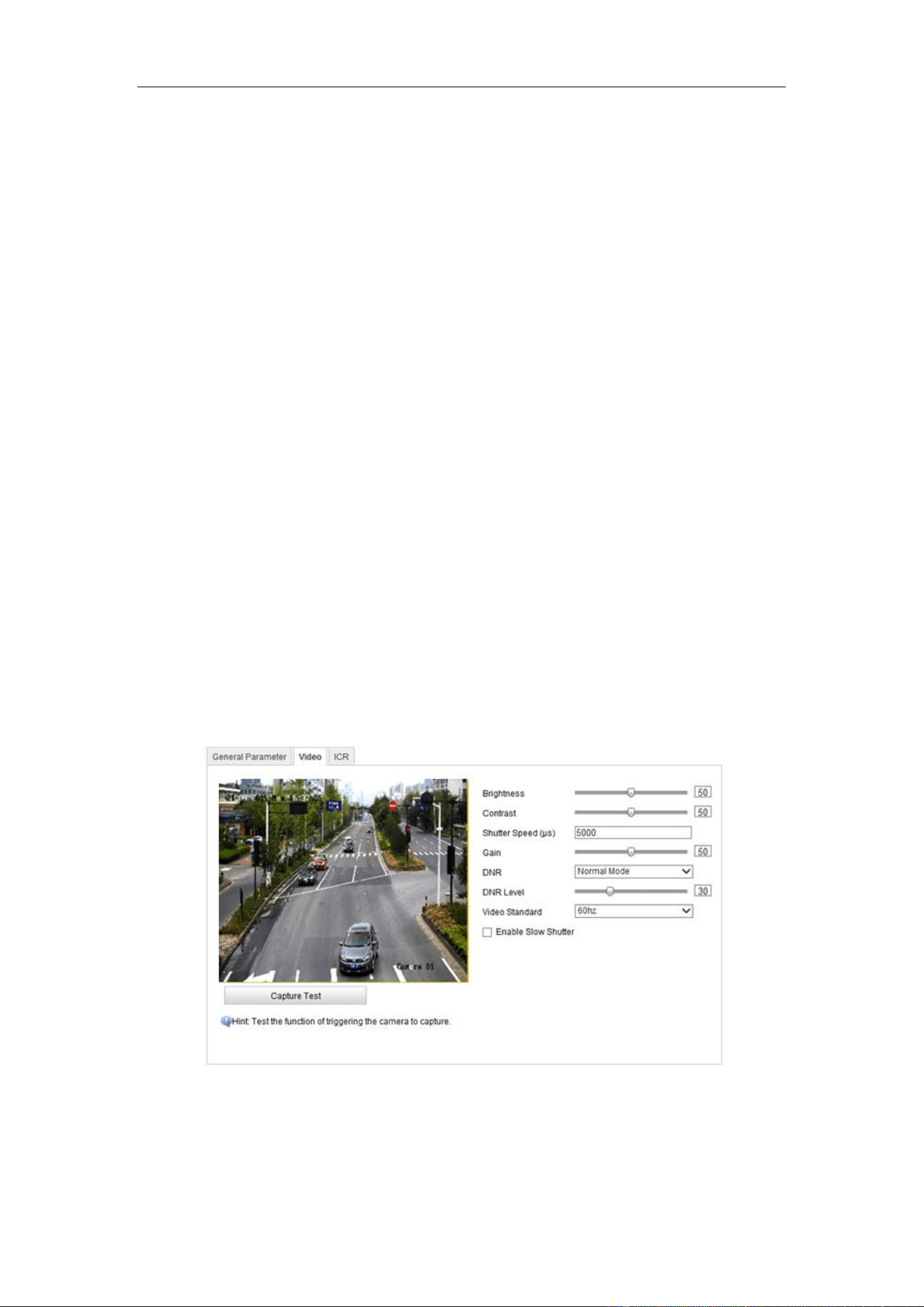
12.2 Video
Purpose:
The camera supports dual-shutter. One shutter for video image, and the other one for
capture image. You can configure shutter parameters for video image on Video tab.
Steps:
1. Enter the video parameters configuration interface: Configuration > Device
Configuration > Image Parameters > Video
Figure 12-2 Video Image
2. Adjust the brightness [0 to100].
3. Adjust the contrast [0 to 100].
User Manual of Video Vehicle Detector
42
4. Input the shutter speed [120 to 40000] μs.
5. Adjust the gain [0 to 100].
6. Select the Video Standard in the dropdown list as 50Hz or 60 Hz.
Note: For countries that adopt PAL Standard, select 50Hz. For countries that adopt
NTSC Standard, select 60Hz.
7. (Optional) Click Capture Test to check the adjustment effects.
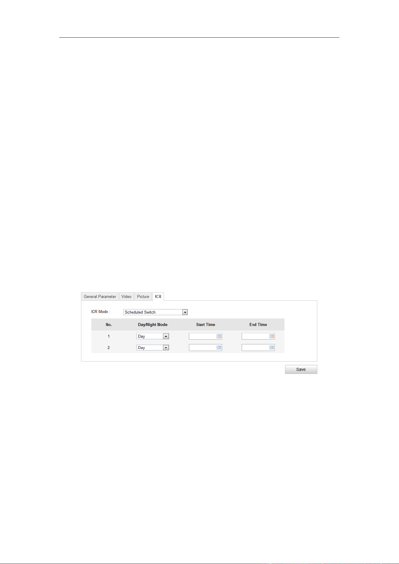
12.3 ICR
Purpose:
IR Cut Filter is used to block or reflect infrared wavelengths but pass visible light.
This series of camera support auto switch of ICR to realize the 24-hour surveillance.
Note: ICR configuration is not supported by all camera models of this series.
Steps:
1. Enter the ICR configuration interface: Configuration > Device Configuration >
Image Parameters > ICR.
Figure 12-3 ICR Interface
2. Select the ICR mode from the drop-down list. Do not Switch, Auto-switch,
Manual Switch, and Scheduled Switch are selectable.
Do not switch: The ICR always stays in day mode by default.
Auto Switch: The ICR switches according to the brightness.
Manual Switch: If you set the ICR mode as Manual Switch, it offers you an
option to select day or night.
Scheduled Switch: The ICR switches according to the configured time schedule.
3. Click Save to save the settings.
User Manual of Video Vehicle Detector
43
Chapter 13 Application Mode
Purpose:
This chapter introduces the parameters configuration under different trigger mode.
The supported trigger modes vary according to the camera models.
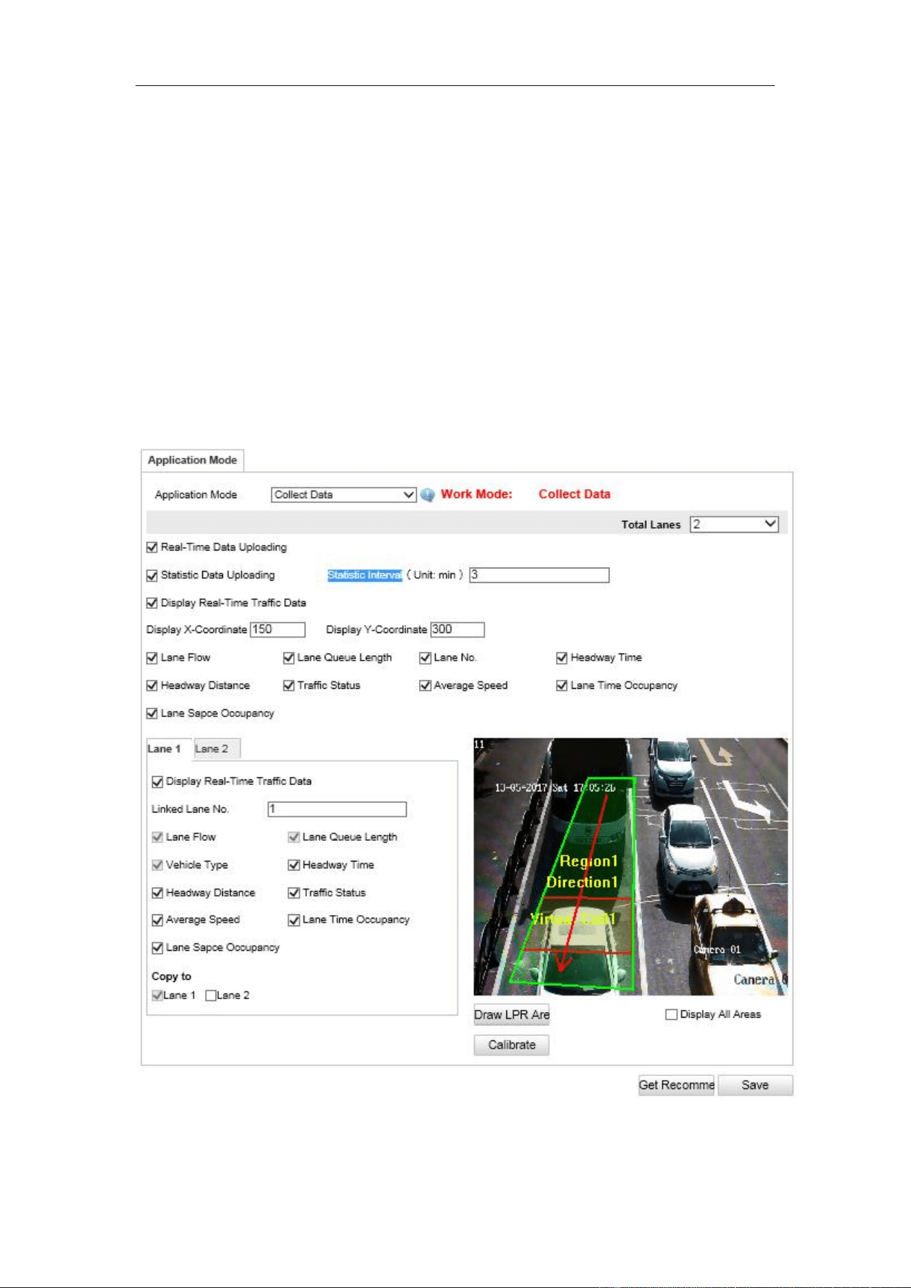
13.1 Application Mode
1. Enter the Application Mode configuration interface. Configuration > Device
Configuration > Application Mode.
Figure 13-1 Application Mode Configuration

User Manual of Video Vehicle Detector
44
2. Select Trigger mode Collect Data.
3. Select the number of lanes to collect data.
4. select“real-time”data upload or “upload statistical data”.
5. Using real-time data upload: vehicle inspection data collection will be uploaded to
the server. Statistical data upload: sensors will collect data according to the time
interval of the upload server set.
6. Set the associated lane number, Select data collection types according to
requirements, such as traffic flow, average vehicle speed, distance between cars of
vertical and horizontal, time & space occupancy, lane queue length, vehicle type,
lane running state etc.
7. Click the "draw area" to enter the lane area configuration interface. Click the
"draw area". In the scene, the left mouse button frames the detection area of the
lane, and right click on the completed area to draw.
8. Click "draw the direction" and draw the direction of the lane in the scene.
9. Click "draw virtual coil" and select one to draw virtual coil in the drawn area.
10. Click OK to complete the zone rendering.
11. Select the remaining lanes and plot the remaining lanes respectively.
12. Click the "calibration" to enter the calibration settings interface. In the actual
scene, select a rectangular area and measure its width and height. The actual width
is high at the calibration interface.
13. Draw the area of the rectangle in the scene. Click OK to complete the calibration
configuration.
14. Click on "save" in the trigger mode tab to complete the data acquisition function
configuration.
15. (Optional) Copy the configuration of current external input to other external
inputs by checking the corresponding checkboxes.
16. Click Save to save the settings.
Note:
You can click the Default button to restore the parameters to default values.
User Manual of Video Vehicle Detector
45
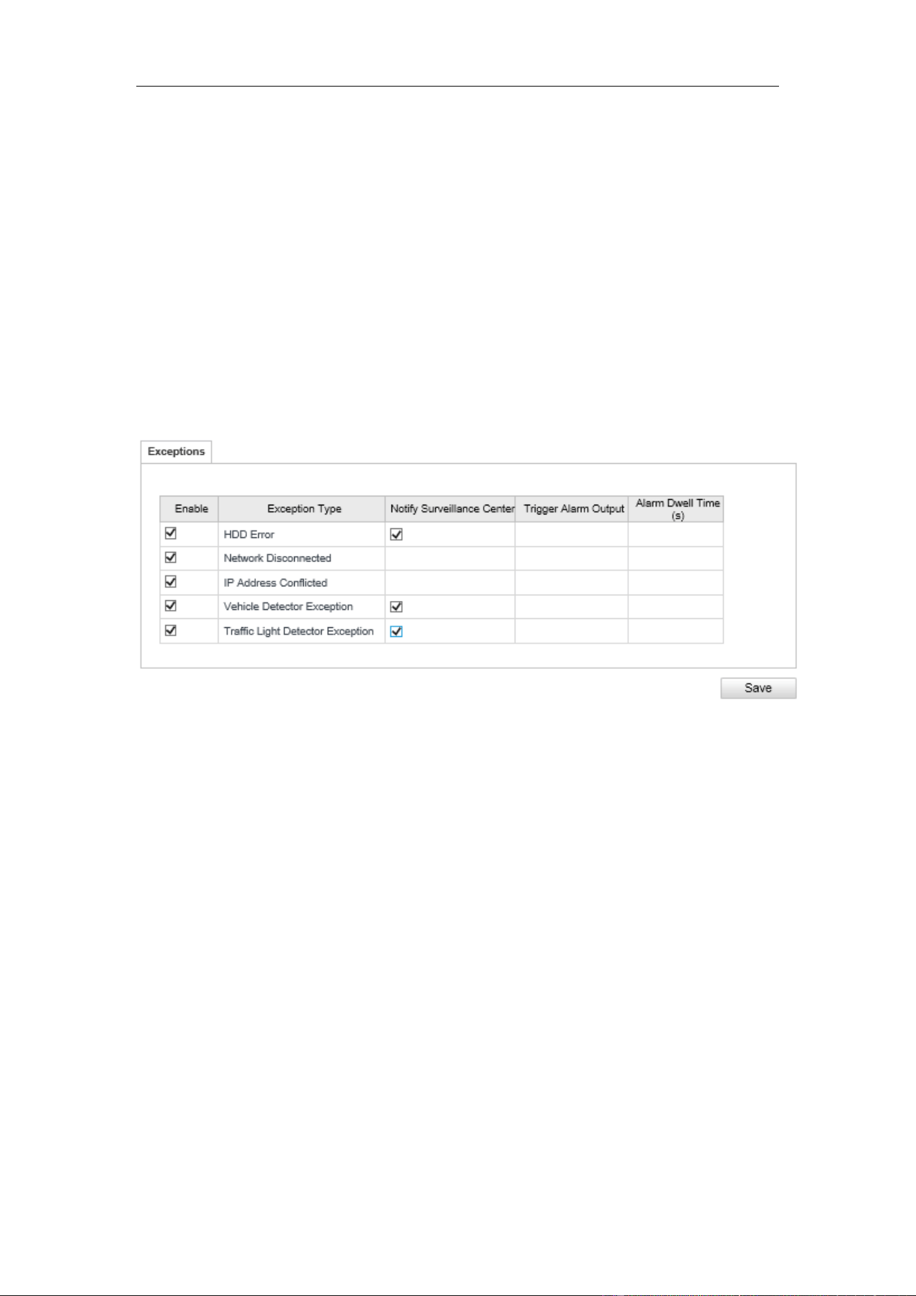
Chapter 14 Exception
The exception type can be HDD error, network disconnected, IP address conflicted
and vehicle detector exception, and traffic light detector exception.
Steps:
1. Enter the Exception Settings interface:
Configuration > Events> Exception
2. Select the exception type and the corresponding trigger methods.
Figure 14-1 Exception Settings
Notify Surveillance Center
Send an exception or alarm signal to remote management software when an event
occurs.
Trigger Alarm Output
Trigger one or more external alarm outputs when an event occurs.
Alarm Dwell Time(s)
The waiting time for the alarm triggered. And you can set the alarm dwell time from 0
to 180s.
3. Click Save to save the settings.
User Manual of Network Traffic Camera
46
Chapter 15 Maintenance
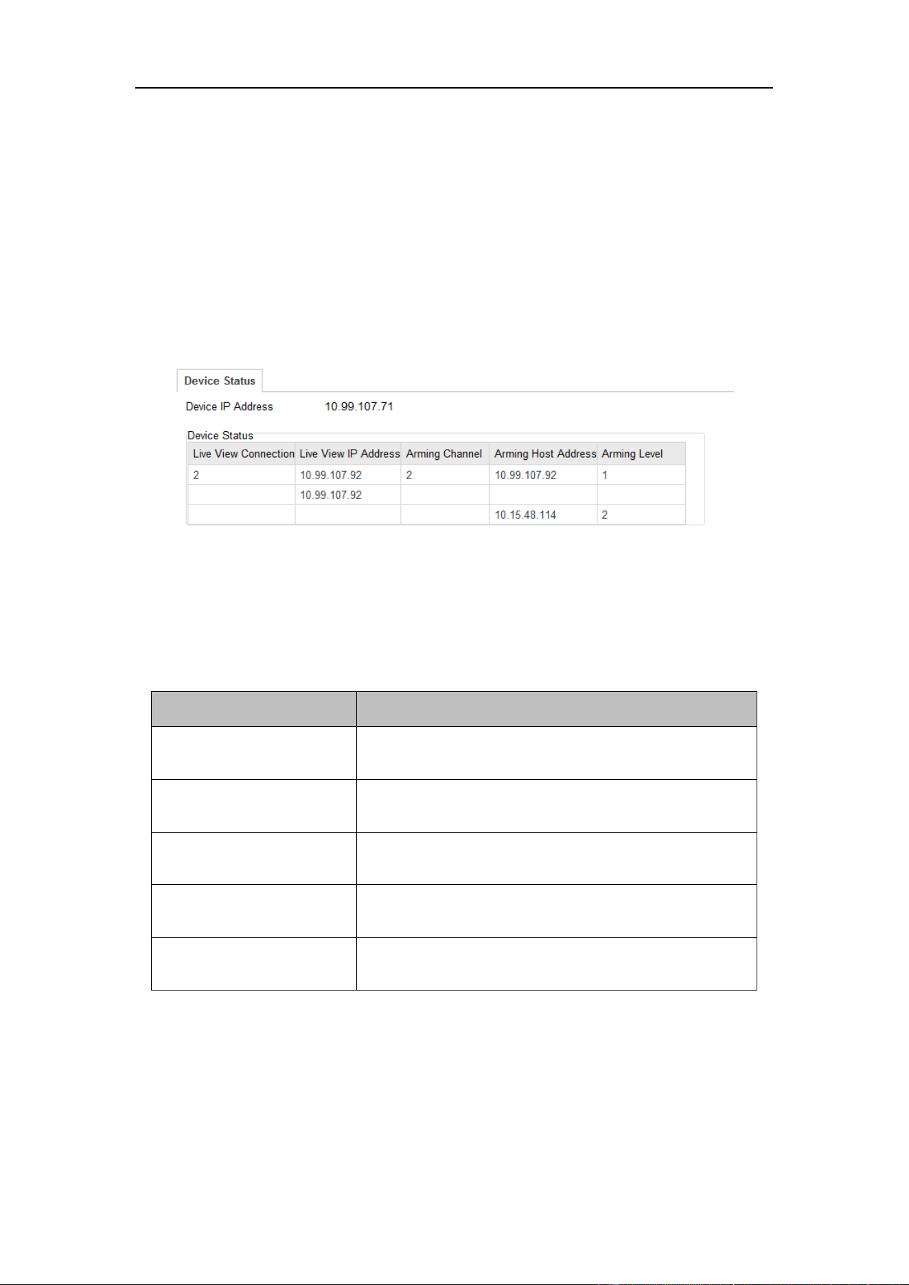
15.1 Checking Device Status
Purpose:
You can check the device status and vehicle detector status from this page.
Check the device and vehicle detector status by click Configuration>Device Status.
Figure 15-1 Device Status
Device IP Address: display the current IP address of the camera.
Device Status: Detailed descriptions are shown in the following table.
Table 15-1 Description of Device Status
Item
Description
Live View Connection
The current number of established live view
connection.
Live View IP Address
The IP address of the PC that is viewing the live
video.
Arming Channel
The number of channel(s) that armed by arming
host(s).
Arming Host Address
The IP address of the host that enables the arming
channel.
Arming Level
Arming level 1 and arming level 2 are available.
Refer to Section 4.4 for detailed explanation.
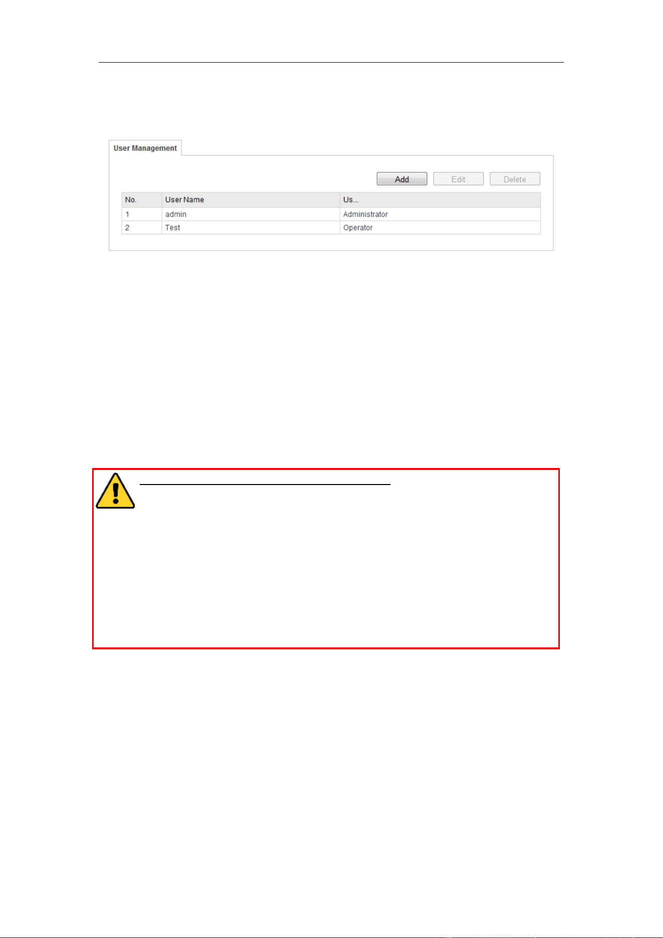
15.2 Managing Users
The admin user should configure the device accounts and user/operator permissions
properly. Delete the unnecessary accounts and user/operator permissions.
User Manual of Video Vehicle Detector
47
Enter the User Management interface:
Configuration >Device Configuration> User Management
Figure 15-2 User Management Interface
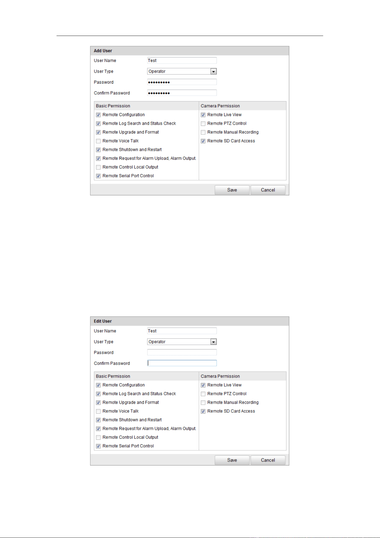
Adding a User
The admin user has all permissions by default and can create / modify / delete other
accounts.
The admin user cannot be deleted and you can only change the admin password.
Steps:
1. Click Add to add a user.
2. Input the User Name and Password.
STRONG PASSWORD RECOMMENDED– We highly recommend you
create a strong password of your own choosing (using a minimum of 8
characters, including at least three of the following categories: upper case
letters, lower case letters, numbers, and special characters) in order to
increase the security of your product. And we recommend you reset your
password regularly, especially in the high security system, resetting the
password monthly or weekly can better protect your product.
Notes:
● Up to 31 user accounts can be created.
● Different level user owns different permissions. Operator and user are
selectable
3. In the Basic Permission field and Camera Permission field, you can check or
uncheck the permissions for the new user.
4. Click Save to finish the user addition.
User Manual of Video Vehicle Detector
48
Figure 15-3 Add a User
Modifying a User
Steps:
1. Left-click to select the user from the list and click Modify.
2. Modify the User Name and Password.
3. In the Basic Permission field and Camera Permission field, you can check or
uncheck the permissions.
4. Click OK to finish the user modification.
Figure 15-4 Modify a User
Deleting a User
User Manual of Video Vehicle Detector
49
Steps:
1. Click to select the user you want to delete and click Delete.
2. Click OK on the pop-up dialogue box to delete the user.
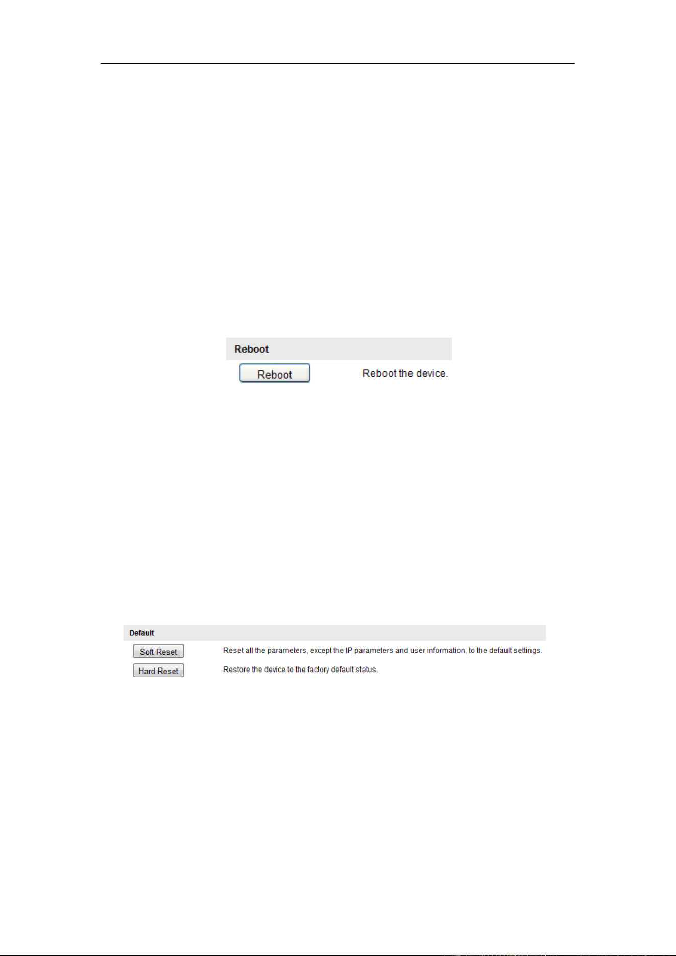
15.3 Rebooting the Camera
Steps:
1. Enter the Maintenance interface:
Configuration > Device Configuration > Maintenance:
2. Click Reboot to reboot the camera.
Figure 15-5 Reboot the Device
15.4 Resetting the Camera
Steps:
1. Enter the Maintenance interface:
Configuration > Device Configuration> Maintenance
2. Two resetting types are supported: Soft Reset and Hard Reset. Click the button to
reset the camera.
Figure 15-6 Restore Default Settings
Note: Use the Hard Reset function with caution.
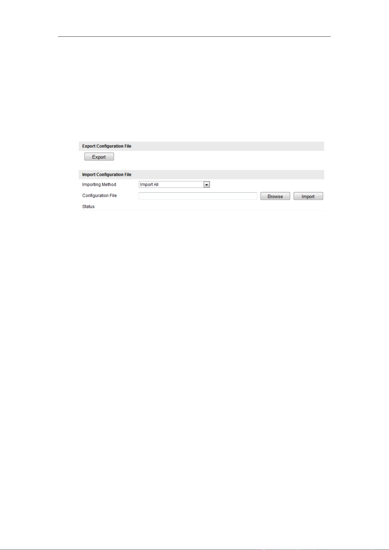
15.5 Exporting/Importing Configuration File
Exporting the Configuration File
Purpose:
User Manual of Video Vehicle Detector
50
If you have configured a camera and want to use the configured parameters as the
example for other cameras, you can export the configuration file to your local PC
directory.
Steps:
1. Enter the Maintenance interface: Configuration > Device Configuration>
Maintenance
Figure 15-7 Import/Export Configuration File
2. Click Export and set the saving path to save the configuration file in local
storage.
Importing the Configuration File
Purpose:
Configuration file is used for the batch configuration of the camera, which can
simplify the configuration steps when there are a lot of cameras needing
configuring.
Steps:
1. Enter the Maintenance interface: Configuration > Device Configuration>
Maintenance
2. Click Export to export the current configuration file, and save it to the certain
place.
3. Select the importing method from the drop-down list. Import all and partial
import are selectable.
4. (Optional) For Partial Import mode, you should select configuration type(s) to
import by checking the corresponding checkbox(s).
5. Click Browse to select the saved configuration file and then click Import to
User Manual of Video Vehicle Detector
51
start importing the configurations.
Note: You need to reboot the camera after importing configurations.
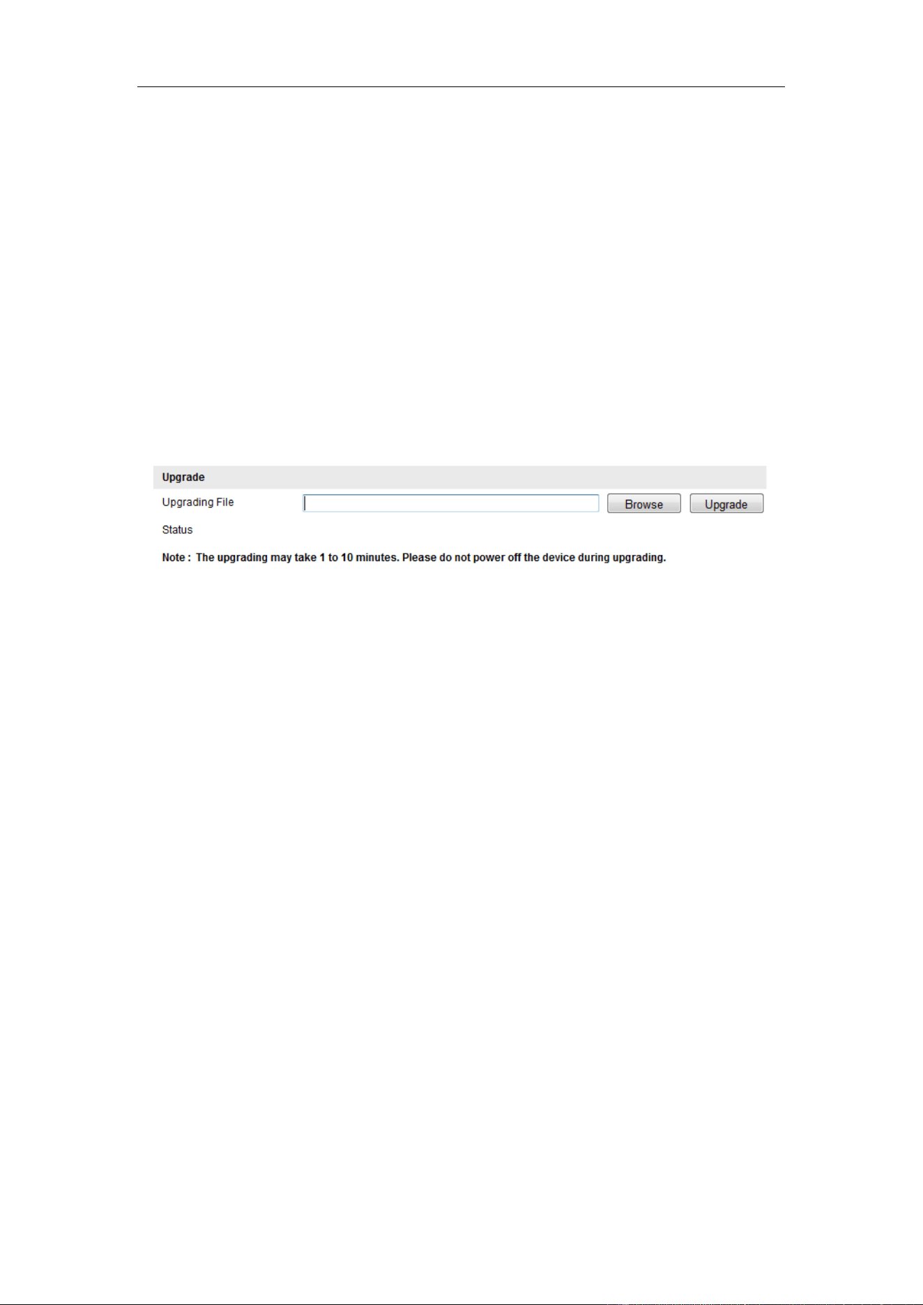
15.6 Upgrading the System
Steps:
1. Enter the Maintenance interface: Configuration > Device Configuration>
Maintenance
2. Click Browse to select the local upgrade file and then click Upgrade to start
remote upgrade.
Figure 15-8 Remote Upgrade
Note: The upgrading process will take 1 to 10 minutes. Do not disconnect power of
the camera during the process, and the camera reboots automatically after upgrade.
User Manual of Network Traffic Camera
52
Appendix
Appendix 1 SADP Software Introduction
Description of SADP
SADP (Search Active Devices Protocol) is a kind of user-friendly and installation-free
online device search tool. It searches the active online devices within your subnet and
displays the information of the devices. You can also modify the basic network
information of the devices using this software.
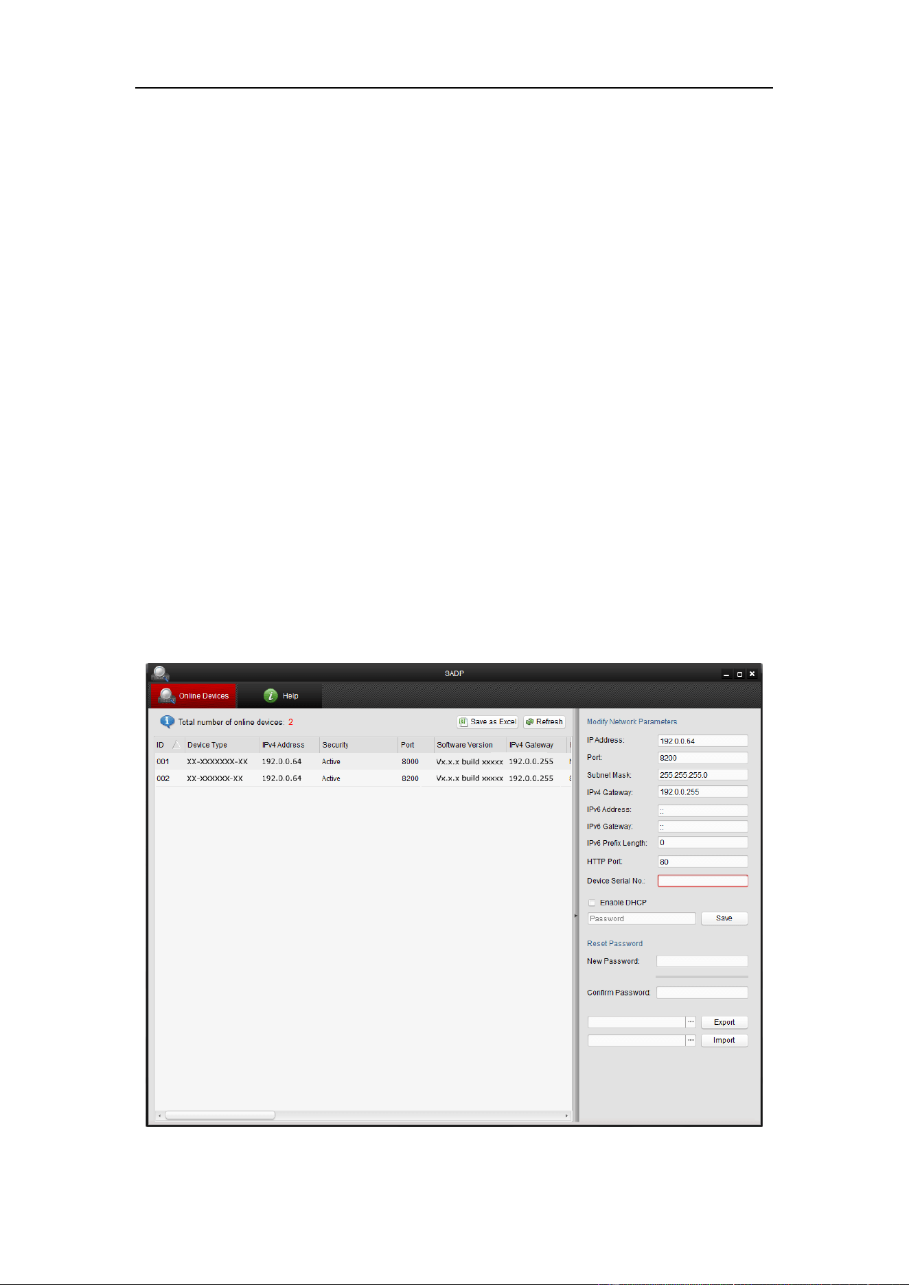
Search active devices online
Search online devices automatically
After launch the SADP software, it automatically searches the online devices
every 15 seconds from the subnet where your computer locates. It displays the
total number and information of the searched devices in the Online Devices
interface. Device information including the device type, IP address and port
number, etc. will be displayed.
Figure A.1.1 Searching Online Devices
User Manual of Video Vehicle Detector
53
Note:
Device can be searched and displayed in the list in 15 seconds after it went
online; it will be removed from the list in 45 seconds after it went offline.
Search online devices manually
You can also click to refresh the online device list manually. The
newly searched devices will be added to the list.
You can click or on each column heading to order the information; you
can click to expand the device table and hide the network parameter panel on the
right side, or click to show the network parameter panel.
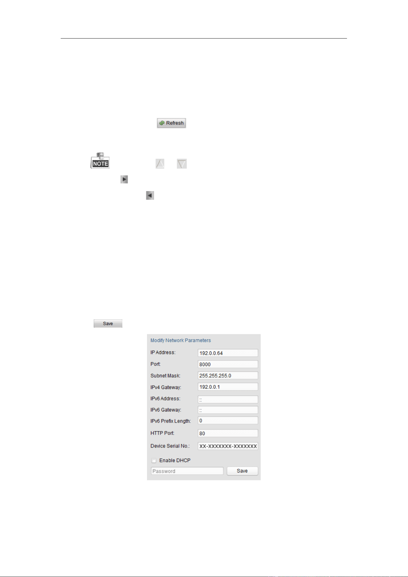
Modify network parameters
Steps:
1. Select the device to be modified in the device list and the network parameters of
the device will be displayed in the Modify Network Parameters panel on the
right side.
2. Edit the modifiable network parameters, e.g. IP address and port number.
3. Enter the password of the admin account of the device in the Password field and
click to save the changes.
Figure A.1.2 Modify Network Parameters
0401001050928

User Manual of Network Traffic Camera
54