February 24, 2022
1
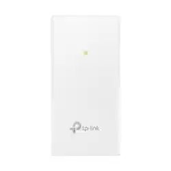
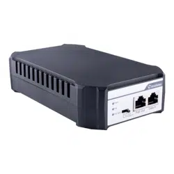
GV-PA903BT Gigabit BT PoE++ Adapter
GV-PA903BT is a Gigabit PoE (Power over Ethernet) adapter. The adapter supports the
IEEE802.3af/at/bt Power over Ethernet standard, with a maximum power output of 95 W over
a single Ethernet cable. You can mount an IP camera anywhere in a building where power
outlets are scarce by using the PoE adaptor.
IP Camera
HUB
Computer
RJ-45
(
Ethernet Cable
)
RJ-45
(
Ethernet Cable
)
Power
Outlet
GV-PA903BT
Packing List
1. GV-PA903BT x 1
2. Power Cord x 1
3. Rubber Feet x 4
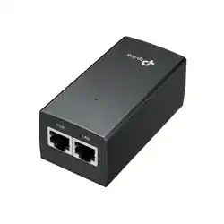
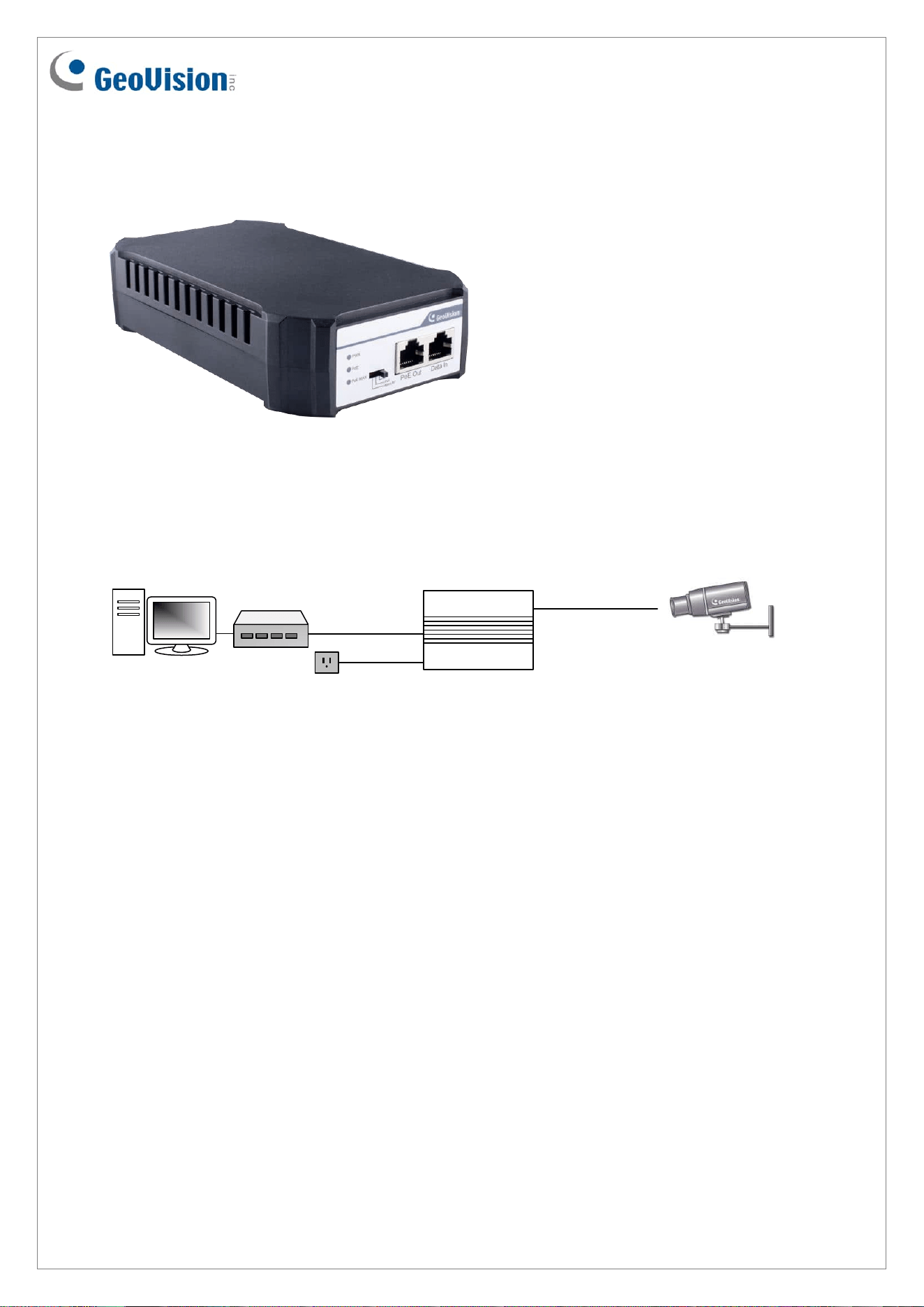
Connections
Two Ethernet cables are required for the connection.
1. Connect one end of the first Ethernet cable into the “Data in” port on the GV-PA903BT,
and the other end to the LAN port on a Hub / Router.
2. Connect one end of the second Ethernet cable into the “PoE Out” port on the GV-
PA903BT, and the other end to the IP camera.
3. Connect the GV-PA903BT to power using the supplied power cord.

February 24, 2022
2
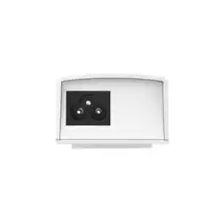
Hardware Description
Front Panel
Intelligent display of PoE power supply
When using the PoE power supply to connect the PD equipment, wait patiently for about 10
seconds while connecting.
LED indicator
LED
Color/Status
Description
PWR
Green On
Power on
Off
Power off
PoE
Green On
Power is supplied to connected devices
PoE MAX
Green On
(Power output
reaches 80%)
Power is supplied to connected devices when the suitable
mode is switched on. 3 modes are available: BT (default),
UPoE, and Legacy BT.
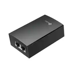
Rear Panel

February 24, 2022
3
Mount Installation
Desktop
To install GV-PA903BT on a leveled surface, attach the four supplied rubber feet at the
bottom of the adapter as illustrated and place it on a leveled surface.
Wall
For wall mount, insert on the desired wall two self-prepared screws that align to the base of
the GV-PA903BT. Tighten the screws to the point where there are about 1.5 mm left hanging
out and hang the GV-PA903BT onto the screws.
Specifications
For detailed specifications, see Datasheet