
2 MP Series Audio PT
Turret Camera
User Manual
User Manual
Thank you for purchasing our product. If there are any
questions, or requests, do not hesitate to contact the
dealer.
This manual applies to the models below:
Type
Model
I
DS-2CE70DF3T-PTS
II
DS-2CE70D0T-LPTS
This manual may contain several technical incorrect
places or printing errors, and the content is subject to
change without notice. The updates will be added to
the new version of this manual. We will readily improve
or update the products or procedures described in the
manual.
01000020220421

Initiatives on the Use of Video Products
Thank you for choosing Hikvision products.
Technology affects every aspect of our life. As a
high-tech company, we are increasingly aware of the
role technology plays in improving business efficiency
and quality of life, but at the same time, the potential
harm of its improper usage. For example, video
products are capable of recording real, complete and
clear images. This provides a high value in retrospect
and preserving real-time facts. However, it may also
result in the infringement of a third party’s legitimate
rights and interests if improper distribution, use and/or
processing of video data takes place. With the
philosophy of “Technology for the Good”, Hikvision
requests that every end user of video technology and
video products shall comply with all the applicable laws
and regulations, as well as ethical customs, aiming to
jointly create a better community.
Please read the following initiatives carefully:
1. Everyone has a reasonable expectation of privacy,
and the installation of video products should not
be in conflict with this reasonable expectation.
Therefore, a warning notice shall be given in a
reasonable and effective manner and clarify the
monitoring range, when installing video products
in public areas. For non-public areas, a third
party’s rights and interests shall be evaluated
when installing video products, including but not
limited to, installing video products only after
obtaining the consent of the stakeholders, and
not installing highly-invisible video products.
2. The purpose of video products is to record real
activities within a specific time and space and
under specific conditions. Therefore, every user
shall first reasonably define his/her own rights in
such specific scope, in order to avoid infringing
on a third party’s portraits, privacy or other
legitimate rights.
3. During the use of video products, video image
data derived from real scenes will continue to be
generated, including a large amount of biological
data (such as facial images), and the data could
be further applied or reprocessed. Video
products themselves could not distinguish good
from bad regarding how to use the data based
solely on the images captured by the video
products. The result of data usage depends on
the method and purpose of use of the data
controllers. Therefore, data controllers shall not
only comply with all the applicable laws and
regulations and other normative requirements,
but also respect international norms, social
morality, good morals, common practices and
other non-mandatory requirements, and respect
individual privacy, portrait and other rights and
interests.
4. The rights, values and other demands of various
stakeholders should always be considered when
processing video data that is continuously
generated by video products. In this regard,
product security and data security are extremely
crucial. Therefore, every end user and data
controller, shall undertake all reasonable and
necessary measures to ensure data security and
avoid data leakage, improper disclosure and
improper use, including but not limited to,
setting up access control, selecting a suitable
network environment (the Internet or Intranet)

where video products are connected,
establishing and constantly optimizing network
security.
Video products have made great contributions to the
improvement of social security around the world, and
we believe that these products will also play an active
role in more aspects of social life. Any abuse of video
products in violation of human rights or leading to
criminal activities are contrary to the original intent of
technological innovation and product development.
Therefore, each user shall establish an evaluation and
tracking mechanism of their product application to
ensure that every product is used in a proper and
reasonable manner and with good faith.

Regulatory Information
FCC Information
Please take attention that changes or modification not
expressly approved by the party responsible for
compliance could void the user’s authority to operate
the equipment.
FCC compliance: This equipment has been tested and
found to comply with the limits for a Class A digital
device, pursuant to part 15 of the FCC Rules. These
limits are designed to provide reasonable protection
against harmful interference when the equipment is
operated in a commercial environment. This equipment
generates, uses, and can radiate radio frequency energy
and, if not installed and used in accordance with the
instruction manual, may cause harmful interference to
radio communications. Operation of this equipment in a
residential area is likely to cause harmful interference in
which case the user will be required to correct the
interference at his own expense.
FCC Conditions
This device complies with part 15 of the FCC Rules.
Operation is subject to the following two conditions:
1. This device may not cause harmful interference.
2. This device must accept any interference received,
including interference that may cause undesired
operation.
EU Conformity Statement
This product and - if applicable - the
supplied accessories too are marked with
"CE" and comply therefore with the
applicable harmonized European
standards listed under the Low Voltage Directive
2014/35/EU, the EMC Directive 2014/30/EU.
2012/19/EU (WEEE directive): Products
marked with this symbol cannot be
disposed of as unsorted municipal waste in
the European Union. For proper recycling,
return this product to your local supplier
upon the purchase of equivalent new
equipment, or dispose of it at designated collection
points. For more information see: www.recyclethis.info.
2006/66/EC (battery directive): This product contains a
battery that cannot be disposed of as
unsorted municipal waste in the European
Union. See the product documentation for
specific battery information. The battery is
marked with this symbol, which may
include lettering to indicate cadmium (Cd), lead (Pb), or
mercury (Hg). For proper recycling, return the battery
to your supplier or to a designated collection point. For
more information, see: www.recyclethis.info.
Industry Canada ICES-003 Compliance
This device meets the CAN ICES-3 (A)/NMB-3(A)
standards requirements.
Safety Instruction
These instructions are intended to ensure that user can
use the product correctly to avoid danger or property
loss.
The precaution measure is divided into “Warnings” and
“Cautions”.
Warnings: Serious injury or death may occur if any of
the warnings are neglected.
Cautions: Injury or equipment damage may occur if any
of the cautions are neglected.
Warnings
In the use of the product, you must be in strict
compliance with the electrical safety regulations of
the nation and region.
Input voltage should meet both the SELV (Safety Extra
Low Voltage) and the Limited Power Source with 12
VDC according to the IEC60950-1 and IEC62368-1
standard. Refer to technical specifications for detailed
information.
The socket-outlet shall be installed near the
equipment and shall be easily accessible.
An all-pole mains switch shall be incorporated in the
electrical installation of the building.
Do not connect multiple devices to one power
adapter to avoid over-heating or a fire hazard caused
by overload.
Make sure that the plug is firmly connected to the
power socket.
If smoke, odor or noise rise from the device, turn off
the power at once and unplug the power cord, and
then contact the service center.
Never attempt to disassemble the camera by
unprofessional personal.
Cautions
No naked flame sources, such as lighted candles,
should be placed on the equipment.
Install the equipment according to the instructions in
this manual.
To prevent injury, this equipment must be securely
attached to the floor/wall in accordance with the
installation instructions.
Do not drop the camera or subject it to physical
shock.
Do not touch senor modules with fingers.
Do not place the camera in extremely hot, cold (the
operating temperature shall be -40°C to 60°C), dusty
or damp locations, and do not expose it to high
electromagnetic radiation.
If cleaning is necessary, use clean cloth with a bit of
ethanol and wipe it gently.
Do not aim the camera at the sun or extra bright
places.
Warnings Follow
these safeguards to
prevent serious injury
or death.
Cautions Follow these
precautions to prevent
potential injury or
material damage.
The sensor may be burned out by a laser beam, so
when any laser equipment is in using, make sure that
the surface of sensor will not be exposed to the laser
beam.
Do not expose the device to high electromagnetic
radiation or extremely hot, cold, dusty or damp
environment.
To avoid heat accumulation, good ventilation is
required for the operating environment.
Keep the camera away from liquid while in use for
non-water-proof device.
While in delivery, the camera shall be packed in its
original packing, or packing of the same texture.
Mark Description
Table 0-1 Mark Description
Mark
Description
DC Voltage
1 Introduction
1.1 Main Features
1.1.1 Type I Camera
High performance CMOS sensor
Low illumination, 0.0005 Lux @ (F1.0, AGC ON), 0 Lux
with white light
24/7 Color Imaging
OSD menu with configurable parameters
Auto white balance
SMART Light
2-axis adjustment
1.1.2 Type II Camera
High performance CMOS sensor
Low illumination, 0.01 Lux @ (F1.2, AGC ON), 0 Lux
with IR
IR cut filter
Support white and IR supplement light
OSD menu with configurable parameters
Auto white balance
SMART IR
2-axis adjustment
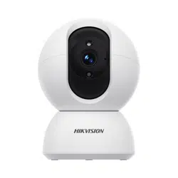
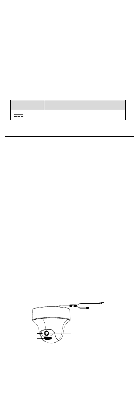
1.2 Overview
Power Cord
Video Output
Lens
Microphone
Supplement Light
Figure 1-1 Overview of the Camera

2 Installation
Before you start:
Make sure that the device in the package is in good
condition and all the assembly parts are included.
Make sure that all the related equipment is power-off
during the installation.
Check the specification of the products for the
installation environment.
Check whether the power supply is matched with
your power output to avoid the damage.
Make sure the wall is strong enough to withstand
three times the weight of the camera and the
bracket.
If the wall is cement, insert expansion bolts before
installing the camera. If the wall is wooden, use
self-tapping screws to secure the camera.
If the product does not function properly, contact
your dealer or the nearest service center. DO NOT
disassemble the camera for repair or maintenance by
yourself.
2.1 Ceiling Mounting
Steps:
1. Secure the adapter plate to the ceiling with three
screws.
Figure 2-1 Secure the Adapter Plate to the Wall
2. Align the camera with the adapter plate and rotate
the camera to finish installation.
Figure 2-2 Finish Installation
3. Connect the corresponding cables.
4. Power on the camera to check whether the image
on the monitor is gotten from the optimum angle. If
not, adjust the camera according to the figure below
to get an optimum angle.
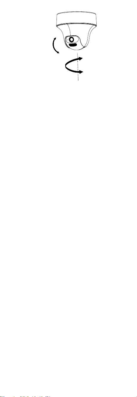
0° to 75°
0° to 350°
Figure 2-3 2-Axis Adjustment
NOTE:
DO NOT adjust the angle of the main body or enclosure
manually. Adjust the pan and tilt angle through the DVR
menu or Hik-Connect.
3 Menu Description
Please follow the steps below to call the menu.
NOTE:
The menu description part is for your reference only. It
might have some differences due to the specific model
that you have.
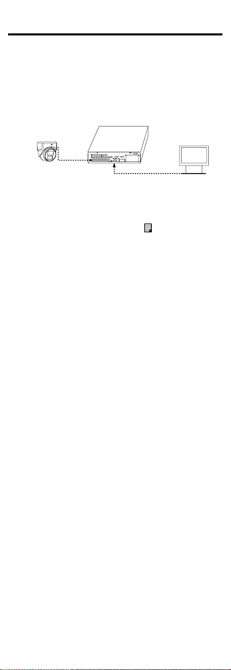
Steps:
1. Connect the camera with the TVI DVR, and the
monitor, shown as the figure 3-1.
Camera
TVI DVR
Monitor
Figure 3-1 Connection
2. Power on the camera, TVI DVR, and the monitor to
view the image on the monitor.
3. Click PTZ Control to enter the PTZ Control interface.
4. Call the camera menu by clicking button, or call
preset No. 95.
EXPOSURE
EXPOSURE MODE
MAIN MENU
VIDEO
SETTINGS
EXIT
SAVE & EXIT
CONTRAST
SHARPNESS
SATURATION
MIRROR
BACK
VIDEO
FORMAT
FACTORY
DEFAULT
BRIGHTNESS
EXIT
SAVE & EXIT
*LIGHTNING
SETTINGS
BACK
EXIT
SAVE & EXIT
IMAGE MODE
BACK
*DNR
AUDIO
SETTINGS
VOLUME
BACK
EXIT
AGC
EXIT
SAVE&EXIT
LIGHTNING MODE
WHITE BALANCE
AUDIO
SAVE & EXIT
*SMART
LIGHT
THRESHOLD
LEVEL
MODE
LIGHT
BACK
*FUNCTIONS
PRIVACY
BACK
EXIT
MOTION DET
SAVE & EXIT
*SLOW SHUTTER
*ANTI-BANDING
*3DNR
SAVE & EXIT
EXIT
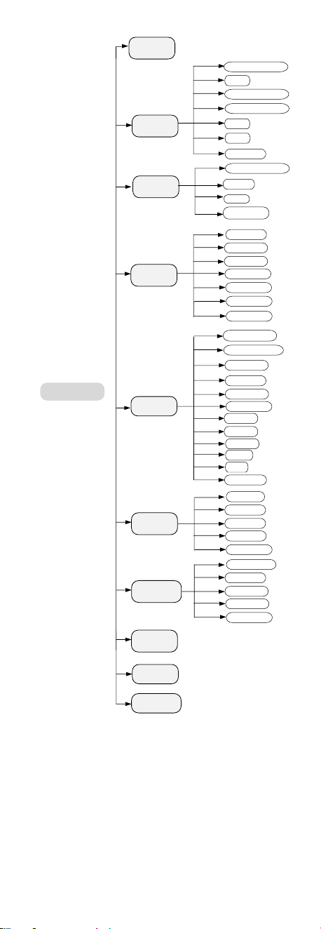
Figure 3-2 Main Menu Overview
Note:
* indicates that the function is supported by some
models.
5. Click the direction arrow to control the camera.
1) Click up/down direction button to select the
item.
2) Click Iris + to confirm the selection.
3) Click left/right direction button to adjust the
value of the selected item.

3.1 VIDEO FORMAT
You can select the video format as 2 MP @ 25 fps or 2
MP @ 30 fps.
You can also select PAL, or NTSC in CVBS mode.
3.2 EXPOSURE
EXPOSURE MODE
You can set the EXPOSURE MODE to GLOBAL, BLC, HLC,
WDR (supported by Type I camera), DWDR (supported
by Type II camera), or HLS (supported by Type I
camera).
GLOBAL
GLOBAL refers to the normal exposure mode which
adjusts lighting distribution, variations, and
non-standard processing.
BLC (Backlight Compensation)
The BLC (backlight compensation) function can
compensate light to the object in the front to make it
clear, but this causes the over-exposure of the
background where the light is strong.
HLC (Highlight Compensation)
HLC stands for highlight compensation. The camera
detects the strong spots (the over-exposure portion of
image), then reduce the brightness of the strong spots
to improve the overall images.
WDR (Wide Dynamic Range)
The wide dynamic range (WDR) function helps the
camera provide clear images even under back light
circumstances. When there are both very bright and
very dark areas simultaneously in the field of view, WDR
balances the brightness level of the whole image and
provide clear images with details.
Note:
WDR is only supported by Type I camera.
DWDR (Digital Wide Dynamic Range)
Digital wide dynamic range gives the camera the ability
to view dark areas of the given image as well as
extremely lighted portions of the image, or areas of
high contrast.
Note:
DWDR is only supported by Type II camera.
HLS (Highlight Suppression)
It is the same visual effect as the solar eclipse. If the
brightness of a part in the image exceeds the threshold,
this part will become black. Then whole image can be
clear.
Note:
HLS is only supported by Type I camera.
AGC
It optimizes the clarity of the image in poor light
conditions. The AGC level can be set to HIGH, MEDIUM,
or LOW.
Note:
The noise will be amplified when setting the AGC level.
SLOW SHUTTER
SLOW SHUTTER increases the exposure time on a single
frame, which makes a camera more sensitive to the
light so it can produce images even in low lux
conditions.
You can set the SLOW SHUTTER function to OFF, ×2, ×4,
×8, or ×16 according to the different light conditions.
Note:
SLOW SHUTTER is only supported by Type I camera.

ANTI-BANDING
ANTI-BANDING is to prevent the phenomenon of
horizontal lines (banding) when photographing images
in low frequency light or high brightness environments.
Note:
ANTI-BANDING is only supported by Type I camera.
3.3 LIGHTNING SETTINGS
Note:
LIGHTNING SETTINGS is only supported by Type II
camera.
LIGHTNING MODE
You can set the LIGHTNING MODE to IR or WHITE
LIGHT.
IR
Set the LIGHTNING MODE to IR.
IR LIGHT
You can turn on/off the IR LIGHT to meet the
requirements of different circumstances.
SMART IR
The Smart IR function is used to adjust the light to its
most suitable intensity, and prevent the image from
over exposure. The SMART IR value can be adjusted
from 0 to 3 as shown below. The greater the value is,
the more obvious effects are.
LIGHTNING SETTINGS
MODE
IR LIGHT
SMART IR
D-N THRESHOLD
N-D THRESHOLD
BACK
EXIT
SAVE&EXIT
AUTO
ON
2
2
7
Figure 3-3 DAY/NIGHT
DN THRESHOLD (Day to Night Threshold)
Day to Night Threshold is used to control the sensitivity
of switching the day mode to the night mode. You can
set the value from 1 to 9. The larger the value is, the
more sensitive the camera is.
ND THRESHOLD (Night to Day Threshold)
Night to Day Threshold is used to control the sensitivity
of switching the night mode to the day mode. You can
set the value from 1 to 9. The larger the value is, the
more sensitive the camera is.
WHITE LIGHT
Set the LIGHTNING MODE to WHITE LIGHT.
WHITE LIGHT
You can set the WHITE LIGHT as AUTO or OFF.
AUTO
Under the AUTO mode, the white light turns on
automatically as the environment becomes dark.
The THRESHOLD is the environmental light level at
which the white light turns on. You can set the value
from 1 to 3. The greater the value is, the darker the
environment should be to activate the light.
The value of LEVEL controls the brightness of the white
light. The greater the value is, the brighter the light is.
OFF

The white light is always off except when alarm is set
and triggered.
3.4 SMART LIGHT
Note:
SMART LIGHT is only supported by Type I camera.
LIGHT
SMART LIGHT is used to control the integrated white
light and avoid overexposure when the light is on. You
can set the light as AUTO or OFF.
SMART LIGHT
LIGHT
THRESHOLD
LEVEL
MODE
BACK
EXIT
SAVE & EXIT
AUTO
2
5
MODE 1/MODE2
Figure 3-4 SMART LIGHT
AUTO
Under the AUTO mode, the white light turns on
automatically as the environment becomes dark.
The THRESHOLD is the environmental light level at
which the white light turns on. The greater the value is,
the darker the environment should be to activate the
light.
The value of LEVEL controls the brightness of the white
light. The greater the value is, the brighter the light is.
OFF
The white light is always off except when alarm is set
and triggered.
MODE
You can set the MODE to MODE1 or MODE2.
The function is to reduce frame rate in low-light
environment in order to increase SNR and enhance the
brightness of the image.
MODE1: Turn on the function.
MODE2: Turn off the function.
3.5 VIDEO SETTINGS
Move the cursor to VIDEO SETTINGS and click Iris+ to
enter the submenu. IMAGE MODE, WHITE BALANCE,
BRIGHTNESS, CONTRAST, SHARPNESS, SATURATION,
3DNR (for Type I), DNR (for Type II), and MIRROR are
adjustable.
IMAGE MODE
IMAGE MODE is used to adjust the image saturation,
and you can set it to STD (Standard), HIGH-SAT (High
Saturation) or HIGHLIGHT.
WHITE BALANCE
White balance, the white rendition function of the
camera, is to adjust the color temperature according to
the environment. It can remove unrealistic color casts in
the image. You can set WHITE BALANCE mode to AUTO,
or MANUAL.
BRIGHTNESS
Brightness refers to the brightness of the image. You
can set the brightness value from 1 to 9 to darken or
brighten the image. The greater the value is, the
brighter the image is.

CONTRAST
This feature enhances the difference in color and light
between parts of an image. You can set the CONTRAST
value from 1 to 9.
SHARPNESS
Sharpness determines the amount of detail an imaging
system can reproduce. You can set the SHARPNESS
value from 1 to 9.
SATURATION
Adjust this feature to change the saturation of the color.
The value ranges from 1 to 9.
3DNR (Digital Noise Reduction)
The 3DNR function can decrease the noise effect,
especially when capturing moving images in poor light
conditions and delivering more accurate and sharp
image. You can set the 3DNR value from 1 to 9.
Note:
3DNR is only supported by Type I camera.
DNR (Digital Noise Reduction)
DNR refers to digital noise reduction. This function
reduces noise in video stream.
Note:
DNR is only supported by Type II camera.
MIRROR
OFF, H, V, and HV are selectable for mirror.
OFF: The mirror function is disabled.
H: The image flips 180° horizontally.
V: The image flips 180° vertically.
HV: The image flips 180° both horizontally and
vertically.
3.6 AUDIO SETTINGS
AUDIO
Under the AUTO SETTINGS sub-menu, you can set the
mode to ON or OFF.
VOLUME
Adjust the LEVEL to a higher value to raise the volume.
3.7 FUNCTIONS
Note:
FUNCTIONS is only supported by Type I.
MOTION DET
In the user-defined motion detection surveillance area,
the moving object can be detected and the alarm will
be triggered. Up to 4 motion detection areas can be
configured.
Select a MOTION area. Set the MODE to ON. Click the
up/down/left/right button to define the position, and
the size of the area. Set the SENSITIVITY from 1 to 9.
PRIVACY
The privacy mask allows you to cover certain areas
which you don’t want to be viewed, or recorded. Up to
4 privacy areas are configurable.
Select a PRIVACY area. Set the MODE to ON. Click
up/down/left/right button to define the position, and
the size of the area.
3.8 FACTORY DEFAULT
Reset all the settings to the factory default.
3.9 EXIT
Move the cursor to EXIT and click Iris+ to exit the menu.

3.10 SAVE & EXIT
Move the cursor to SAVE & EXIT and click Iris+ to save
the settings, and exit the menu.
UD28106B-A