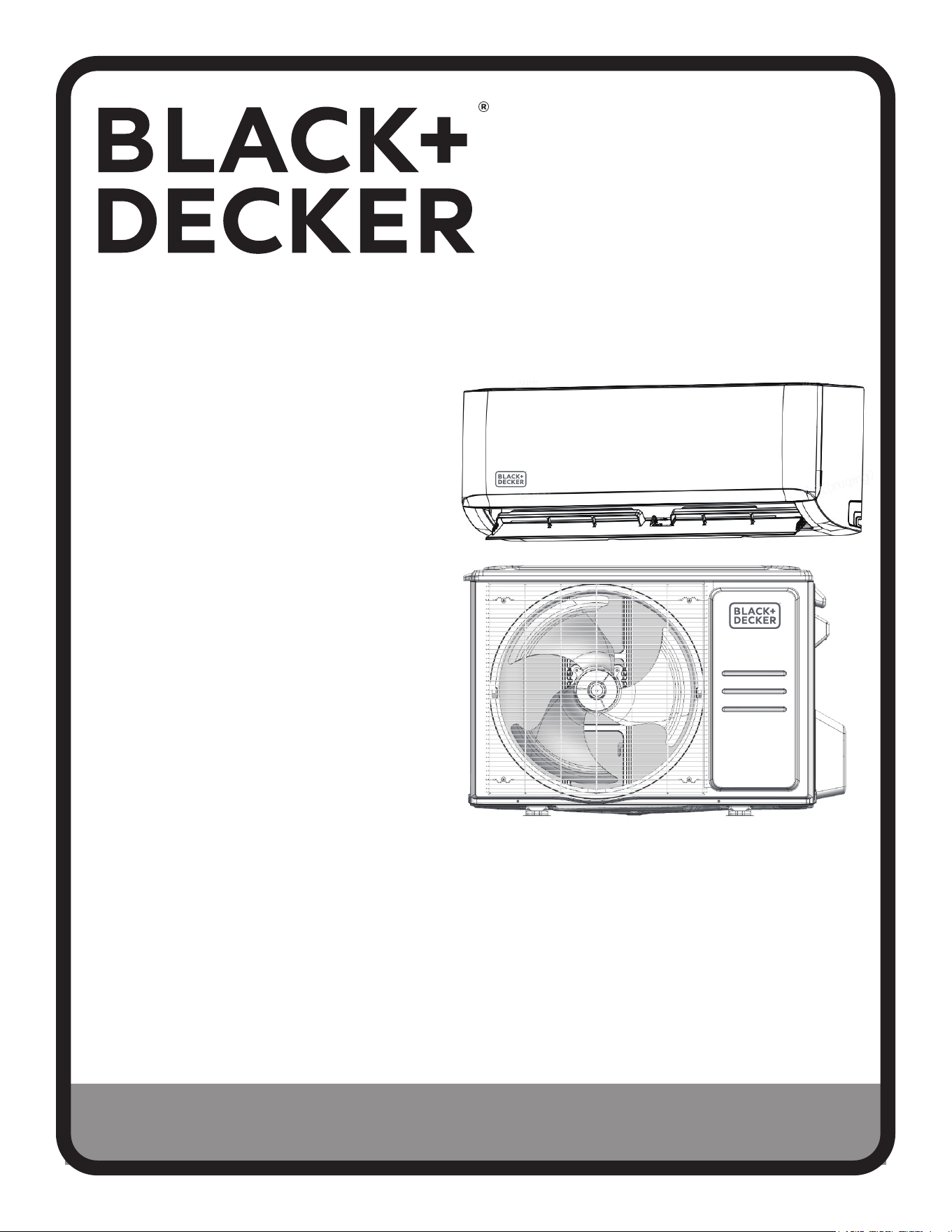
INSTRUCTION MANUAL
INVERTER TECHNOLOGY
SPLIT AIR CONDITIONER
Thank you for choosing BLACK+DECKER!
PLEASE READ BEFORE RETURNING THIS PRODUCT FOR ANY
REASON.
If you have a question or experience a problem with your BLACK+DECKER
purchase, go to www.blackanddecker.com/instantanswers
If you can’t find the answer or do not have access to the Internet, call
844-299-0879 from 10:30 a.m. to 6:30 p.m. EST Mon. - Fri. to speak with an
agent. Please have the catalog number available when you call.
SAVE THIS MANUAL FOR FUTURE REFERENCE.
CATALOG NUMBER
BSA1215MC


Page 3
Thank you for purchasing our
BLACK+DECKER product. This
easy-to-use manual will guide you
in getting the best use of your
split AC.
Remember to record the model and
serial numbers. They are on a label
in the rear.
Staple your receipt to your manual.
You will need it to obtain warranty service.
Model number
Serial number
Date of purchase
CONTENTS
PRODUCT REGISTRATION
SAFETY INFORMATION ............................................................................................................................4-8
SET UP & USE
Operating Conditions ........................................................................................................................................................9
Parts & Features ...........................................................................................................................................................10-14
Indoor Unit Installation .............................................................................................................................................. 15-21
Outdoor Unit Installation ........................................................................................................................................22-24
Refrigerant Piping Connection ............................................................................................................................25-32
Handling Alkaline Batteries ................................................................................................................................... 33-34
Remote Control ..........................................................................................................................................................35-39
CLEANING & CARE ................................................................................................................................... 40-43
TROUBLESHOOTING & WARRANTY ..................................................................................44-45
Page 4
IMPORTANT SAFETY INSTRUCTIONS
• Read this instruction manual before installing and using the appliance.
• All electrical connections, wiring and installation should be performed by a
licensed professional. Otherwise, it may cause personal injury or damage.
Heat pumps, air conditioners & heating equipment should be installed,
started up, and serviced only by qualified licensed professionals and service
technicians. Air conditioning, heat pumps and refrigeration systems are
hazardous due to high voltage electrical components, high refrigerant
pressures, and moving parts.
• This appliance is not intended for use by children without responsible adult supervision.
Proper care should be taken to ensure safety.
• Disconnect electrical power to the indoor and outdoor units before performing any
maintenance or cleaning.
• Do not attempt to repair the system yourself. Incorrect repairs may cause electric shock or
fire. Contact a qualified service technician for all service requirements.
• Keep combustible materials away from the unit.
• DO NOT share the electrical circuit with other appliances. Improper or insucient power
supply can cause fire or electrical shock.
• When connecting refrigerant piping, DO NOT let substances or gases other than the
refrigerant enter the unit. The presence of other gases or substances will lower the unit’s
capacity, and may cause abnormally high pressure in the operation cycle. This may cause
explosion and injury.
• DO NOT allow children to play with the air conditioner. Children should be supervised
around the unit at all times.
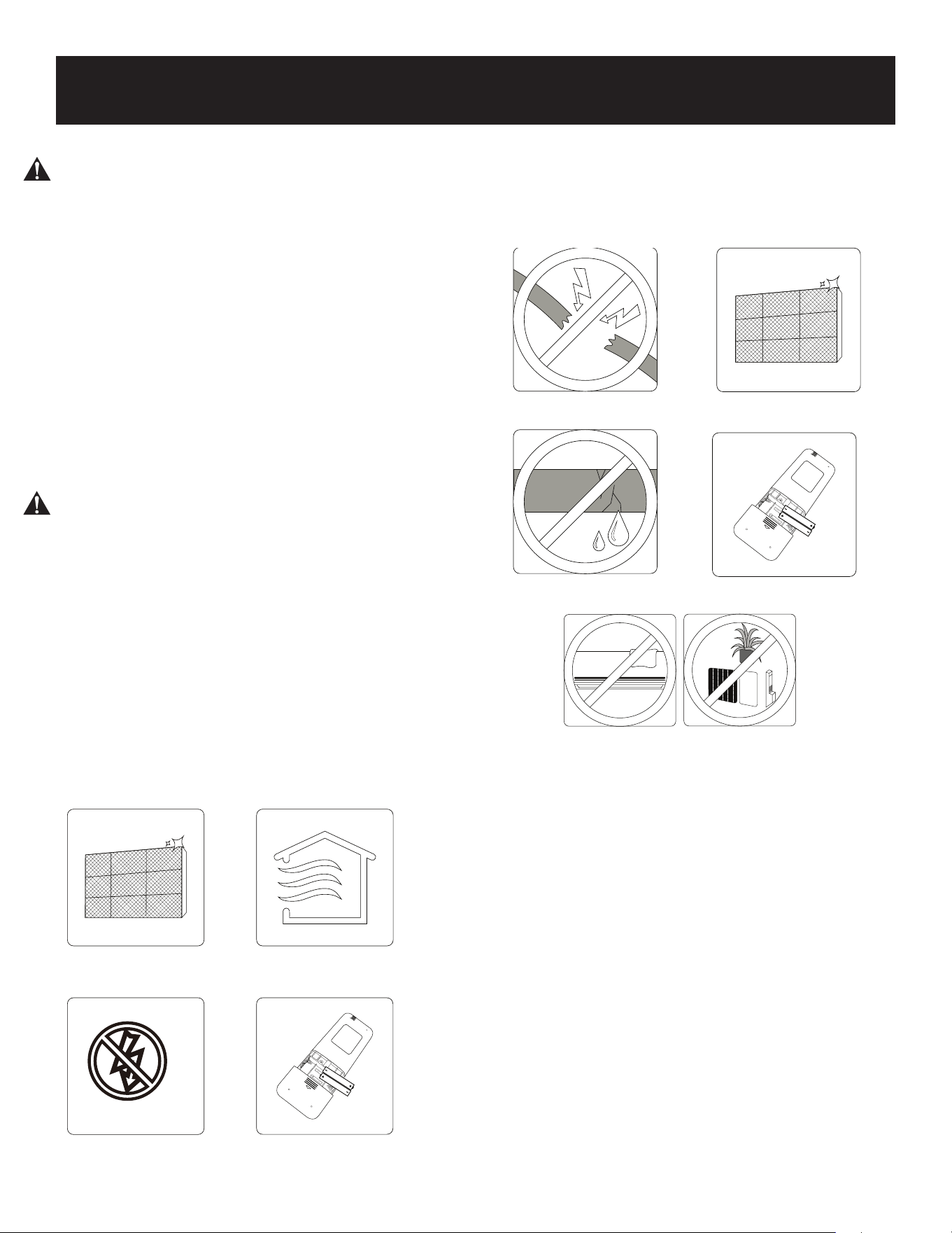
WARNING
When using electrical appliances, basic safety precautions
should be followed, including the following:
SAFETY INFORMATION
DANGER
DANGER - Immediate hazards
which WILL result in severe
personal injury or death
WARNING
WARNING - Hazards or unsafe
practices which COULD result in
severe personal injury or death
CAUTION
CAUTION - Hazards or unsafe
practices which COULD result in
minor personal injury

Page 5
• Installation must be performed according to installation instructions. Improper installation
may cause water leakage, electrical shock, fire, or may void the warranty.
• In North America, service or repair must be performed in accordance with the requirement
of NEC and CEC (by authorized personnel or authority having jurisdiction only.) Contact an
authorized service technician for repair or maintenance of the unit.
• Only use the included accessories and specified parts for installation. Using non-standard
parts can cause water leakage, electrical shock, or fire and may cause the unit to fail.
• For all electrical work. Connect cables tightly, and clamp them securely to prevent external
forces from damaging the terminal. Improper electrical connections may overheat causing
fire and/or electrical shock.
• All wiring must be properly arranged to ensure that the control board cover can close
properly. If the control board cover is not closed properly, it can lead to corrosion and cause
the connection points on the terminal to overheat, causing fire and / or electrical shock.
• This appliance can be used by children aged 8 years and above and persons with reduced
physical, sensory or mental capabilities or lack of experience and knowledge if they have
been given supervision or instruction concerning use of the appliance in a safe way and
understand the hazards involved. Children should not play with the appliance. Cleaning and
user maintenance should not be made by children without supervision.
SAVE THESE INSTRUCTIONS
HOUSEHOLD USE ONLY
NOTE: Your actual air conditioning & heating system and related devices may dier from the
images shown in this manual.
SAFETY INFORMATION
Page 6
• Do not put hands or any objects into the air inlets or outlets. This may cause personal
injury or damage to the unit.
• When cleaning, be careful not to splash water on the unit. Doing this may cause electric
shock or damage to the unit.
• Do not use or place any flammable, combustible or noxious substance next to the unit.
• In the event of a failure (burning smell, etc.), immediately disconnect all electrical
power to indoor and outdoor units.
• Never try repairing the system yourself; contact a qualified service technician for all
repairs.
• During the installation of the indoor and outdoor units, access to the working area
should be o limits to children. Unforeseeable accidents can occur.
• Make sure that the base of the outdoor unit is securely installed and stable before use.
• Check that air cannot enter the refrigerant system and check for refrigerant leaks when
moving the air conditioner.
• Do not install the appliance closer than 20” (50 cm) from flammable substances
(alcohol, etc.) or pressurized containers(e.g. spray cans).
• If the appliance is used in areas without the possibility of ventilation, precautions must
be taken to prevent any leaks of refrigerant gas from remaining in the environment to
avoid creating a fire hazard.
• The packaging materials are recyclable and should be disposed of in separate waste
bins. The air conditioner itself must be taken to a special waste collection center for
proper disposal.
• Only use the air conditioner as instructed in this booklet. These instructions are not
intended to cover every possible condition or situation. As with only electric household
appliance, common sense and caution are therefore always recommended for
installation, operation, and maintenance.
• The appliance must be installed In accordance with NEC and local codes.
• Before accessing the terminals, all the power circuits must be disconnected from the
power supply.
• Do not try to install the air conditioner alone; always contact trained, experienced
personal.
• Cleaning and maintenance must be carried out by a trained and experienced individual
or technician. Make sure to disconnect the appliance from the main’s electrical supply
prior to cleaning or maintenance of the unit.
• Never remain directly exposed to the flow of cold air for extended periods. Direct and
prolonged exposure to cold air could be dangerous to your health.
CAUTION
Please read the following before operation. Safety Rules and
recommendations for the installer.
SAFETY INFORMATION

Page 7
• Particular care should be taken in rooms where there are children, elderly, or sick
individuals.
• If the appliance gives o smoke or there is a burning smell, immediately disconnect the
power supply and contact the Service Center. Prolonged use of the device afterword
could cause fire or electrocution.
• Have repairs or maintenance carried out only by licensed mechanical contractor.
Incorrect repair could expose the user to risk of electric shock, fire hazard, etc..
• The air conditioner itself must be taken to a special waste collection center for proper
disposal.
• This appliance has been made for air conditioning domestic environments and must not
be used for any other purpose, such as for drying clothing, cooling food, etc..
• Always use the appliance with the air filter mounted. The use of the conditioner without
the air filter could cause an excessive accumulation of dust or waste on the inner parts
of the device with possible subsequent failures.
• The user is responsible for having the appliance installed by a licensed mechanical
contractor.
• Disable automatic functions if you foresee not using the device for an extended period
of time. The air flow direction must also be properly adjusted.
• Check all building codes for applicable building permits or requirements.
• Only use the air conditioner as instructed in this manual. These instructions are not
intended to cover every possible condition or situation.
• Ensure that the appliance is disconnected from the power supply when it will not be in
operation for an extended period and before carrying out any cleaning or maintenance.
• Do not use extension cords.
• Do not touch the appliance when barefoot or parts of the body are wet or damp.
• Do not obstruct the air inlet or outlet of the indoor or outdoor units. Obstruction of
these openings causes a reduction in the operating eciency of the air conditioner and
can lead to consequent failures or damages.
• Do not alter the characteristics of the appliance in any way.
• Do not install the appliance in environments where the air could contain gas, oil or
sulphur or near sources of heat.
• This appliance is not intended for use by persons [including children] with reduced
physical, sensory, or mental capabilities, or lack of experience and knowledge unless
they have been given supervision or instruction concerning use of the appliance by a
person responsible for their safety.
• Do not climb onto or place any heavy or hot objects on top of either the indoor or
outdoor unit.
• Do not leave windows or doors open for long when the air conditioner is in operation.
• Do not direct the flow of cold air onto plants or animals. Prolonged direct exposure
to cold air produced by the air conditioner could have negative eects on plants and
animals.
• Do not put the air conditioner in contact with water. The electrical insulation could be
damaged and lead to electrocution.
• Never insert a stick or similar object into the appliance. Such misuse can lead to injury
or damage to the operation of the units.
SAFETY INFORMATION

Page 8
• Children should be supervised to ensure that they do not play with the appliance.
• DO NOT install the unit in a location that may be exposed to combustible gases.
If combustible gas accumulates around the unit, it may cause fire.
• DO NOT operate your air conditioner in a wet room such as a bathroom or laundry
room. Too much exposure to water may cause electrical components to short circuit.
• DO NOT operate the air conditioner with wet hands. This may cause electrical shock.
• DO NOT climb onto or place objects on top of the outdoor unit.
• The product must be properly grounded during installation, or electrical shock may
occur.
• Install drainage piping according to the instructions in this manual. Improper drainage
may cause water damage to your home and property.
SAFETY INFORMATION
TAKE NOTE OF FUSE SPECIFICATIONS
• The air conditioner's circuit board (PCB) is designed with a fuse to provide overcurrent
protection.
• The specifications of the fuse are printed on the circuit board ,such as:
T3.15AL/250VAC, T5AL/250VAC, T3.15A/250VAC, T5A/250VAC, T20A/250VAC,
T30A/250VAC,etc..
Page 9
OPERATING CONDITIONS
• If the air conditioner is operated outside of the specied temperature ranges, certain safety
protection features may activate, leading to the unit to be disabled.
• When the temperature is too high, the air conditioner may activate the automatic
protection device, so that the air conditioner could be shut down.
• When the temperature is too low, the heat exchanger of the air conditioner may freeze,
leading to water leakage or other malfunction.
• In long-term cooling or dehumidication with a relative humidity of above 80% (doors and
windows are open), there may be water condensation or dripping near the air outlet.
NOTES FOR HEATING
• The fan of the indoor unit will not start running immediately after the heating is started to
avoid blowing out cool air.
• When it is cold and wet outside, the outdoor unit will develop frost over the heat exchanger
which will compromise the heating capacity. This is when the air conditioner will start to
defrost.
• During defrost, the air conditioner will stop heating for about 5-12 minutes. Vapor may
come out from the outdoor unit during defrost. This is not a malfunction, but a result of fast
defrost.
• Heating will resume after defrost is complete.
NOTE: When the outdoor temperature is below 32°F (0°C) it is recommended to keep the unit
plugged in at all times to ensure smooth ongoing performance.
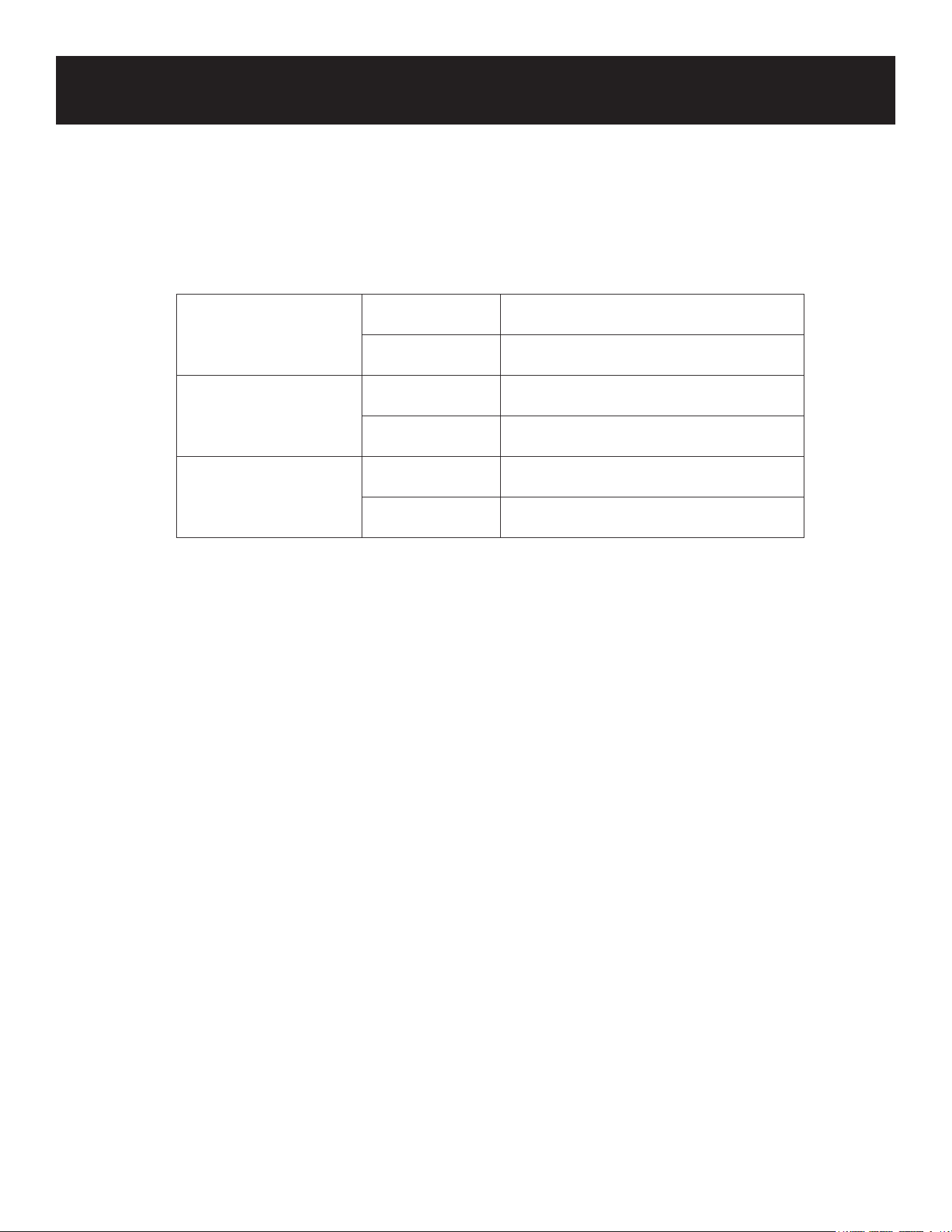
Cool Mode
Outdoor 32°F - 122°F (0°C - 50°C)
Indoor 60°F - 90°F (16°C - 32°C)
Heat Mode
Outdoor 5°F - 75°F (15°C - 24°C)
Indoor 32°F - 86°F (0°C - 30°C)
Dry Mode
Outdoor 32°F - 122°F (0°C - 50°C)
Indoor 50°F - 90°F (10°C - 32°C)
SET UP & USE
Page 10
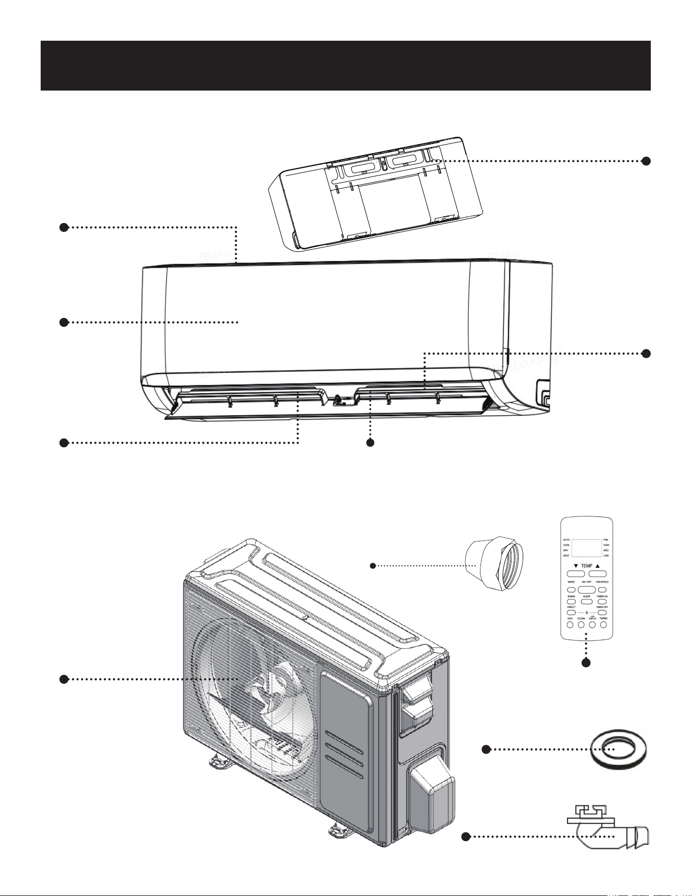
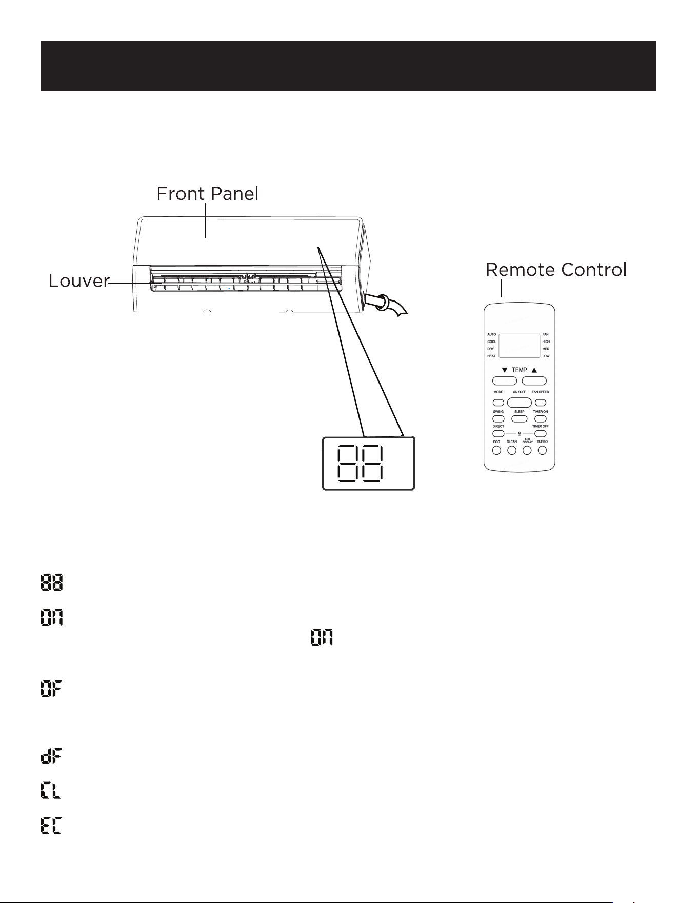
PARTS & FEATURES
INDOOR UNIT
Air Inlet Grill
Panel
Air Vent
Remote Control
Seal
SET UP & USE
Louver
Mounting Plate
5 screws and 5 wall
anchors for the
mounting plate
OUTDOOR UNIT
1 Large filter (not shown; inside unit)
1 small filter packed with indoor unit
Copper flare nut
(2 pcs)
Air Outlet Grill
Drain Joint
Page 11
SET UP & USE
Accessory Kits:
The following Black + Decker Refrigerant
Accessory Kits are sold separately and
compatible with BSA1215MC
Black + Decker Model: BSAK1
9.8 Ft. Refrigerant Line Set with Copper Flared
Fittings.
• ¼” diameter x 9 ft. 10 in. length liquid line
• ½” diameter x 9 ft. 10 in. length suction line
Includes:
• 16 ft. 4.85 in. Drainage Tubing
• Wall Hole Cover
• Wall Hole Sleeve
• Sealant
• Tape
Black + Decker Model: SAK2
16.4 Ft. Refrigerant Line Set with Copper Flared
Fittings.
• ¼” diameter x 16 ft. 4.85 in. length liquid line
• ½” diameter x 16 ft. 4.85 in. length suction line
Includes:
• 16 ft. 4.85 in. Drainage Tubing
• Wall Hole Cover
• Wall Hole Sleeve
• Sealant
• Tape
BSAK3
24.6 Ft. Refrigerant Line Set with Copper Flared
Fittings.
• ¼” diameter x 24 ft. 7.27 in. length liquid line
• ½” diameter x 24 ft. 7.27 in. length suction line
Includes:
• 16 ft. 4.85 in. Drainage Tubing
• Wall Hole Cover
• Wall Hole Sleeve
• Sealant
• Tape
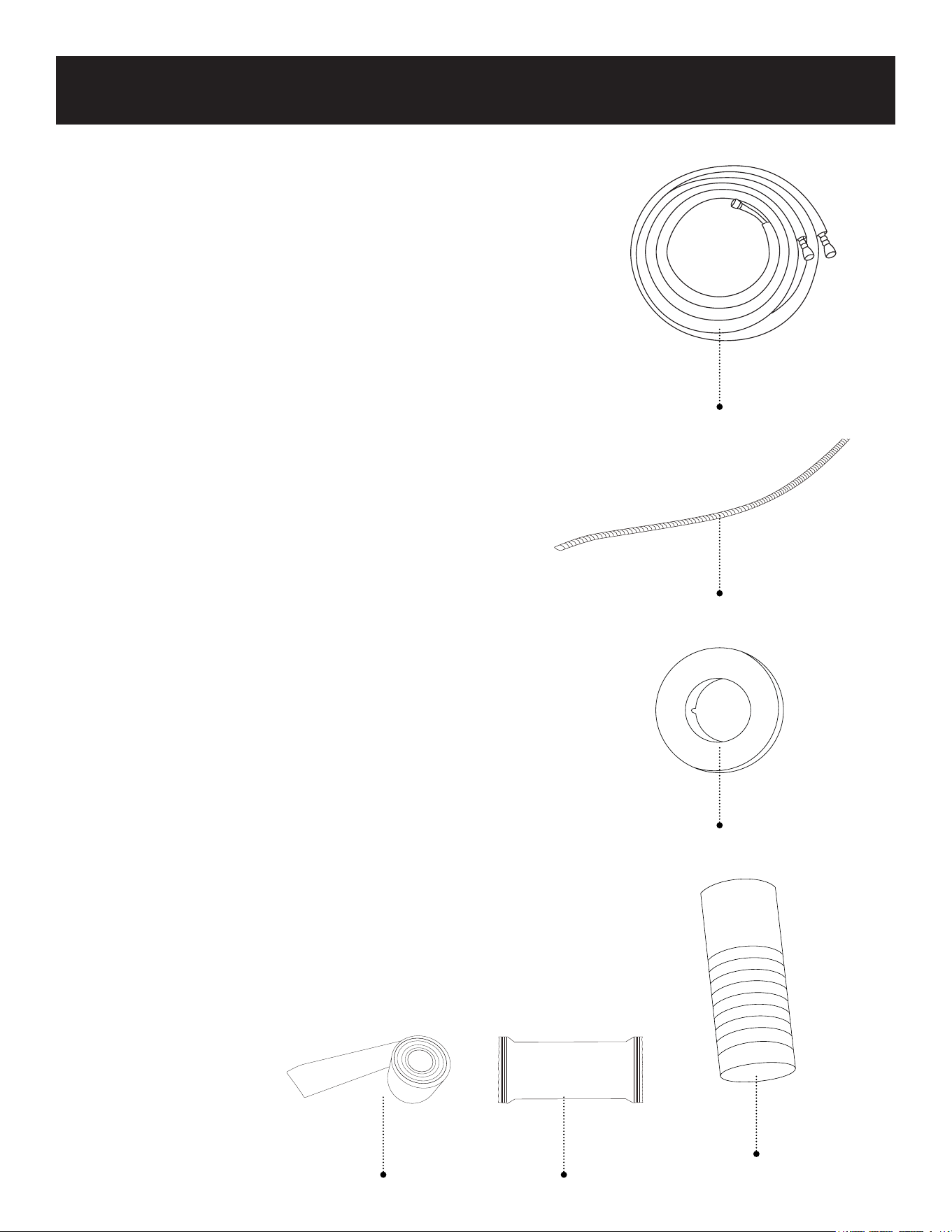
Refrigerant Pipe
Drainage Tubing
Wall Hole Cover
Wall Hole Sleeve
Tape
Sealant

Page 12
SET UP & USE
TO BE SUPPLIED BY INSTALLER BASED ON
SPECIFIC INSTALLATION LOCATION. (not included with the unit)
Refrigerant Piping
Liquid line 1/4" (6.35 mm) diameter
Suction Line 1/2" (12.7 mm) diameter
Drain hose/Condensate drain
Wall Hole Sleeve
Sealant
Wiring supplies, Wrapping Tape, etc.
M10 bolts (to secure the outdoor unit)
SUGGESTED TOOLS FOR INSTALLATION (Not included)
• Adjustable wrenches
• Screwdriver
• Core Drill
• Tape measure
• Power drill
• Hammer
Page 13
SET UP & USE
WARNING: All electrical connections, wiring and installation should be performed by a
licensed professional. The installation must be performed in accordance with
the requirement of local and national standards.
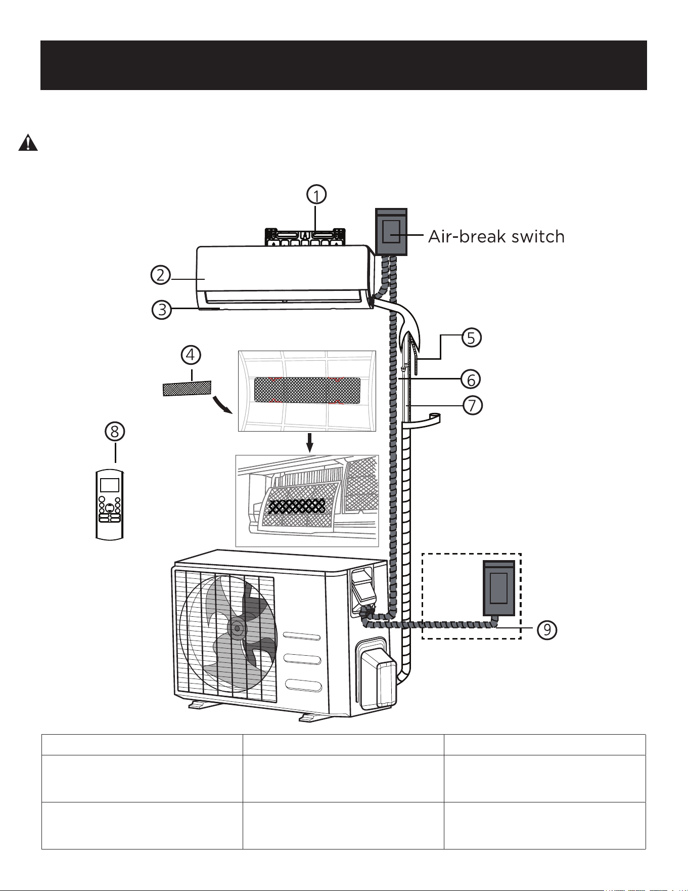
UNIT PARTS
1. Wall Mounting Plate 2. Front Panel 3. Louver
4. Filters (2 pieces)
1 Large Filter,
1 Small Filter
5. Drainage Tubing 6. Electrical Wiring
7. Refrigerant Piping
1/4” diameter liquid line
1/2” gas/suction line
8. Remote Control 9. Outdoor Unit Power Cable
Page 14
SET UP & USE
INDOOR UNIT
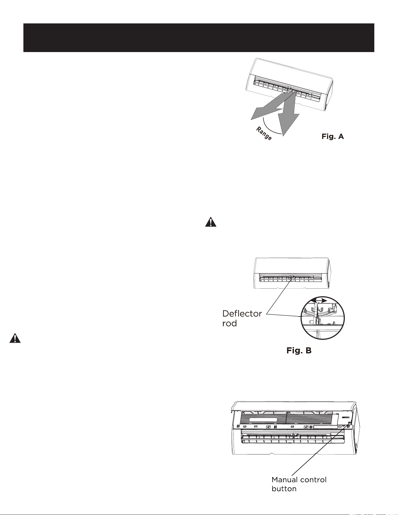
Setting Angle of Air Flow
Setting vertical angle of air flow
While the unit is on, use the SWING/DIRECT
button on remote control to set the direction
(vertical angle) of airflow. Please refer to the
Remote Control Manual for details.
NOTE ON LOUVER ANGLES
When using COOL or DRY mode, do not set
louver at too vertical an angle for long
periods of time. This can cause water to
condense on the louver blade, which will drop
on your floor or furnishings.
When using COOL or HEAT mode, setting the
louver at too small an angle can reduce the
performance of the unit due to restricted air
flow.
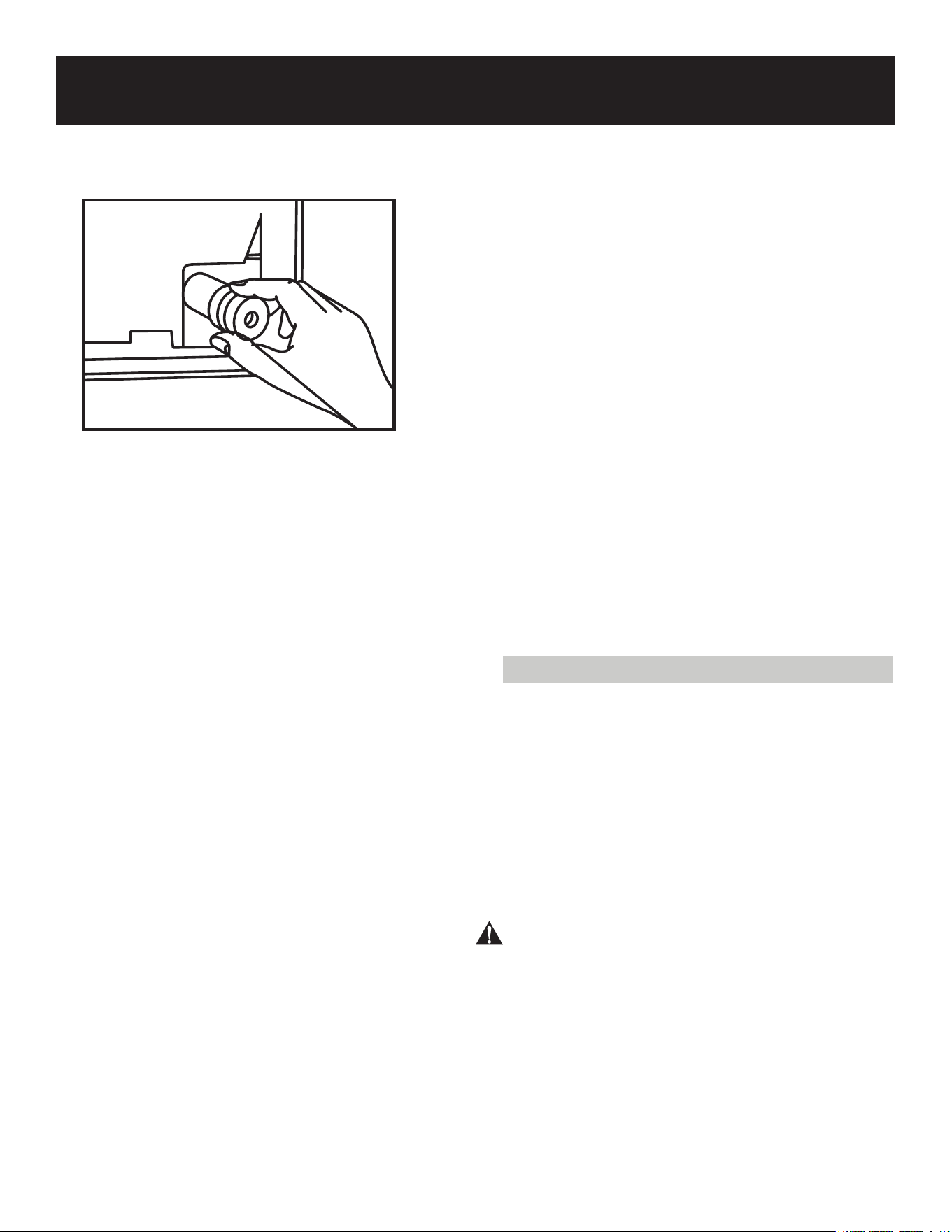
Setting horizontal angle of air flow
The horizontal angle of the airflow must be set
manually. Grip the deflector rod (See Fig. B)
and manually adjust it to your preferred
direction.
The DIRECT button on the remote will adjust
the angle of the louvers 6 degrees at a time.
Manual Operation (without remote)
CAUTION
The manual button is intended for testing
purposes and emergency operation only.
Please do not use this function unless the
remote control is lost and it is absolutely
necessary. To restore regular operation, use the
remote control to activate the unit. Unit must
be turned o before manual operation.
To operate your unit manually:
1. Open the front panel of the indoor unit.
2. Locate the MANUAL CONTROL button on the right
hand side of the unit.
3. Press the MANUAL CONTROL button one time to
activate FORCED AUTO mode.
4. Press the MANUAL CONTROL button again to
activate FORCED COOLING mode.
5. Press the MANUAL CONTROL button a third time to
turn the unit o.
6. Close the front panel.
NOTE: Do not move louver by hand.
This will cause the louver to become
out of sync. If this occurs, turn o the
unit and unplug it for a few seconds,
then restart the unit. This will reset the
louver.
CAUTION: Do not put your fingers in
or near the blower and suction side of
the unit. The high-speed fan inside the
unit may cause injury.
Page 15
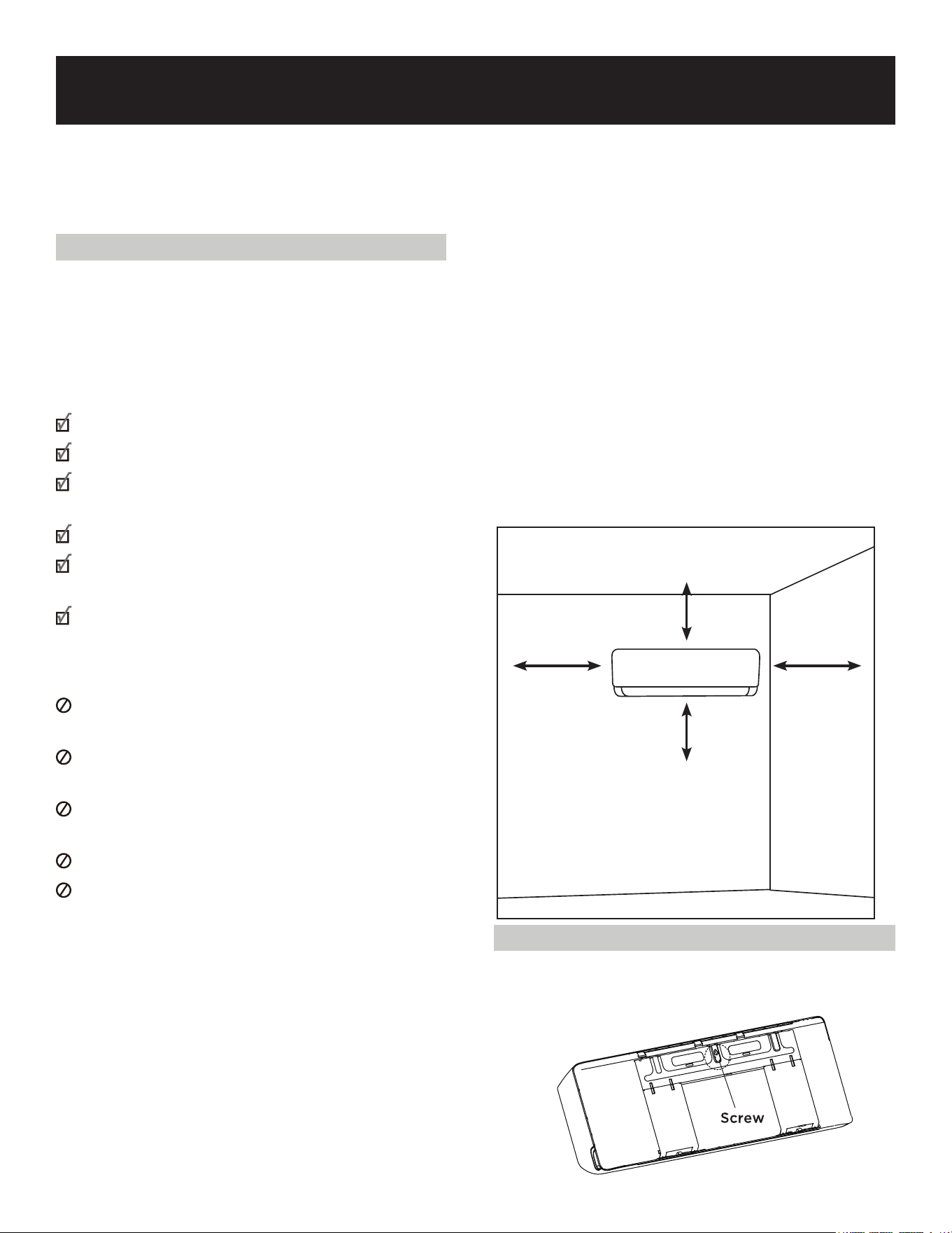
Minimum Space to the ceiling 5.9
inches (15 cm)
Minimum Space to
Adjacent Wall 4.75
inches (12 cm)
Minimum Space
to Adjacent Wall
4.75 inches
(12 cm)
Minimum Space to the floor
78.7 inches
SET UP & USE
INDOOR UNIT INSTALLATION
Installation Instructions - Indoor unit
Step 1: Select installation location
Before installing the indoor unit, you must
choose an appropriate location. The following
are standards that will help you choose an
appropriate location for the unit.
Proper installation locations meet the
following standards:
Good air circulation
Convenient drainage
Noise from the unit will not disturb other
people
Firm and solid-the location will not vibrate
Strong enough to support the weight of the
unit
A location at least one meter from all other
electrical devices (e.g. TV, radio, computer)
DO NOT install unit in the following locations:
Near any source of heat, steam, or
combustible gas
Near flammable items such as curtains or
clothing
Near any obstacle that might block air
circulation
Near the doorway
In a location subject to direct sunlight
NOTE ABOUT WALL HOLE:
If there is no existing refrigerant piping:
While choosing a location, be aware that you
should leave ample room for a wall hole (see
Drill wall hole for connective piping step)
for the signal cable and refrigerant piping
that connect the indoor and outdoor units.
The default position for all piping is the right
side of the indoor unit (while facing the unit).
However, the unit can accommodate piping
to both the left and right.
Refer to the following diagram to ensure
proper distance from walls and ceiling:
Step 2: Attach mounting plate to wall
• Remove the screw that attaches the
mounting plate to the back of the indoor
unit.
Page 16
SET UP & USE
• Secure the mounting plate to the wall with the screws provided. Make sure that mounting
plate is flat against the wall. Screws should be secured into studs in the wall.
NOTE FOR CONCRETE OR BRICK WALLS:
If the wall is made of brick, concrete, or similar material, drill 0.2” (5mm) diameter holes in the
wall and insert the wall anchors provided. Then secure the mounting plate to the wall by
tightening the screws directly into the wall anchors.
WARNING: Suitable screws will need to be used for the specific type of wall to properly anchor
the air conditioner.
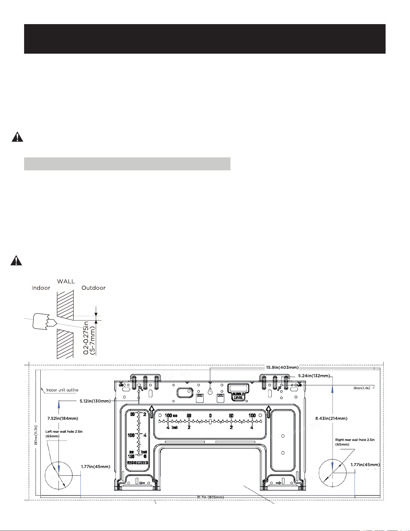
Step 3: Drill wall hole for connective piping
1. Determine the location of the wall hole based on the position of the mounting plate.
Refer to Mounting Plate Dimensions.
2. Using a 2.5” (65mm) core drill, drill a hole in the wall. Make sure that the hole is drilled
at a slight downward angle, so that the outdoor end of the hole is lower than the indoor
end by about 0.2”-0.275” (5mm to 7mm). This will ensure proper water drainage.
3. Place the protective wall cu in the hole. This protects the edges of the hole and will
help seal it when you finish the installation process.
CAUTION:
Make sure there are no pipes or wires behind the wall before drilling or cutting the hole.
Page 17
SET UP & USE
Step 4: Prepare refrigerant piping
The refrigerant piping is inside an
insulating sleeve attached to the back of
the unit. You must prepare the piping
before passing it through the hole in the
wall.
1. Based on the position of the wall hole
relative to the mounting plate, choose
the side from which the piping will exit
the unit.
2. If the wall hole is behind the unit, keep
the knock-out panel in place. If the wall
hole is to the side of the indoor unit,
remove the plastic knock-out panel
from that side of the unit. This will
create a slot through which your piping
can exit the unit. Use needle nose
pliers if the plastic panel is too dicult
to remove by hand.
3. If existing connective piping is already
embedded in the wall, proceed directly
to the Connect Drain Hose step. If there
is no embedded piping, connect the
indoor unit’s refrigerant piping to the
connective piping that will join the
indoor and outdoor units. Refer to the
Refrigerant Piping Connection section
of this manual for detailed instructions.
NOTE ON PIPING ANGLE
Refrigerant piping can exit the indoor unit
from four dierent angles: Left-hand side,
Right-hand side, Left rear, Right rear.
CAUTION
Be extremely careful not to dent or damage
the piping while bending them away from the
unit. Any dents in the piping will aect the
unit’s performance.
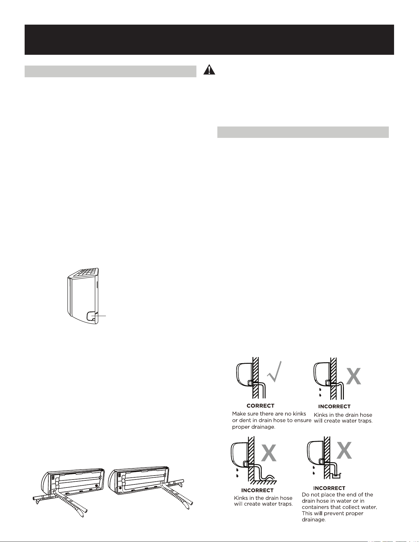
Step 5: Connect drain hose
To ensure proper drainage, attach a drain
hose on the same side that your refrigerant
piping exits the unit. Attach drain hose
extension (purchased separately) to the
end of drain hose.
• Wrap the connection point firmly with
Teflon tape to ensure a good seal and to
prevent leaks.
• For the portion of the drain hose that
will remain indoors, wrap it with foam
pipe insulation to prevent condensation.
• Remove the air filter and pour a small
amount of water into the drain pan to
make sure that water flows from the
unit smoothly.
NOTE ON DRAIN HOSE PLACEMENT
Make sure to arrange the drain hose
according to the following figures.
Knock-out Panel
Page 18
SET UP & USE
PLUG THE UNUSED DRAIN HOLE
To prevent unwanted leaks you must plug
the unused drain hole with the rubber
plug provided.
BEFORE PERFORMING ANY
ELECTRICAL WORK, READ THESE
REGULATIONS
1. All wiring must comply with local and
national electrical codes, regulations and
must be installed by a licensed
electrician.
2. All electrical connections must be made
according to the Electrical Connection
Diagram located on the panels of the
indoor and outdoor units.
3. If there is any safety issue with the
power supply, stop working immediately.
Do not install the unit until the safety
issue is properly resolved.
4. Power voltage should be within 90-110%
of rated voltage. Insucient power
supply can cause malfunction, electrical
shock, or fire.
5. If connecting power to fixed wiring, a
surge protector and main power switch
should be installed.
6. If connecting power to fixed wiring, a
switch or circuit breaker that
disconnects all poles and has a
contact separation of at least 1/8in
(3mm) must be incorporated in the fixed
wiring. The qualified technician must use
an approved circuit breaker or switch.
7. Only connect the unit to an individual
branch circuit outlet. Do not connect an-
other appliance to that outlet.
8. Make sure to properly ground the air
conditioner.
9. Every wire must be firmly connected.
Loose wiring can cause the terminal to
overheat resulting in product
malfunction and possible fire.
10. Do not let wires touch or rest against
refrigerant tubing, the compressor, or any
moving parts within the unit.
11. If the unit has an auxiliary electric
heater, it must be installed at least 1
meter (40in) away from any combustible
materials.
12. To avoid getting an electric shock, never
touch the electrical components soon
after the power supply has been turned
o. After turning o the power, always
wait 10 minutes or more before you
touch the electrical components.
Step 6: Connect signal and power cables
The signal cable enables communication
between the indoor and outdoor units. You
must first choose the right cable size before
preparing it for connection.
CHOOSE THE CORRECT CABLE SIZE
NOTE: Choose the right cable size
according to the Minimum Circuit
Amps indicated on the rating label of
the unit.
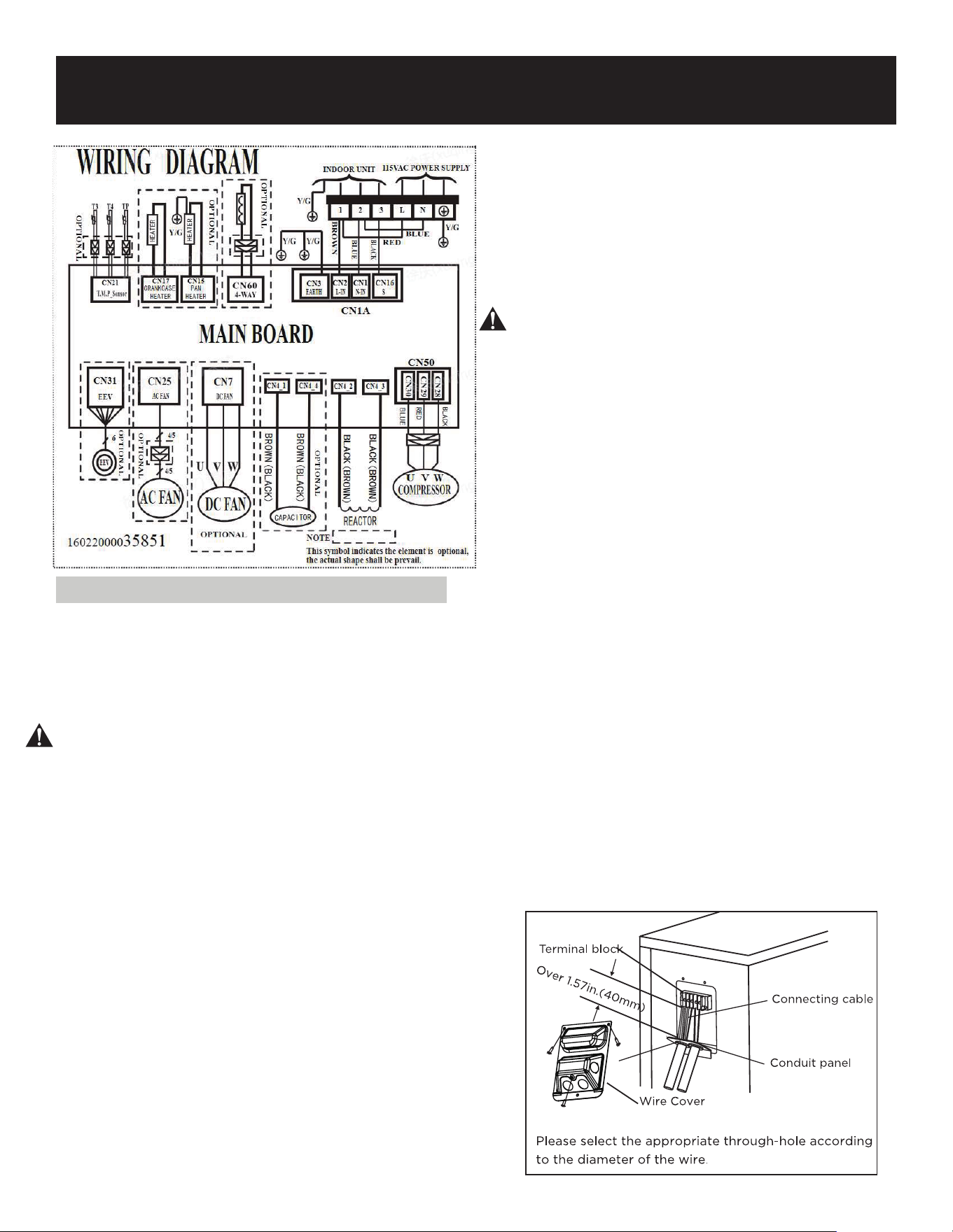
WARNING
All wiring must be performed strictly in
accordance with the wiring diagram located
on the back of the indoor unit’s front panel.
See wiring diagram on top of Page 19.

Page 19
SET UP & USE
1. Open front panel of the indoor unit.
2. Using a screwdriver, open the wire box cover
on the right side of the unit. This will reveal the
terminal block.
WARNING
Before performing any electrical or wiring work, turn o main power to the system.
CAUTION
DO NOT MIX UP LIVE AND NULL WIRES
This is dangerous, and can cause the air
conditioning unit to malfunction.
For the units with five-core cable, remove
the middle small plastic knock-out panel
to create a slot through which the cable
can exit.
Use needle nose pliers if the plastic panel
is too dicult to remove by hand.
3. Unscrew the cable camp below the terminal
block and place it to the side.
4. Facing the back of the unit, remove the plastic
panel on the bottom left-hand side.
5. Feed the signal wire through this slot, from the
back of the unit to the front.
6. Facing the front of the unit, connect the wire
according to the indoor unit’s wiring diagram
connect the u-lug and firmly screw each wire
to its corresponding terminal.
7. After checking to make sure every connection
is secure, use the cable clamp to fasten the
signal cable to the unit. Screw the cable clamp
down tightly.
8. Replace the wire cover on the front of the unit,
and the plastic panel on the back.
Page 20
NOTE ABOUT WIRING
THE WIRING CONNECTION PROCESS MAY DIFFER SLIGHTLY BETWEEN UNITS AND
REGIONS
1. Bundle the drain hose, refrigerant pipes, and signal cable as shown below.
DRAIN HOSE MUST BE ON BOTTOM
Make sure that the drain hose is at the bottom of the bundle. Putting the drain hose at the top
of the bundle can cause the drain pan to overflow, which can lead to fire or water damage.
DO NOT INTERTWINE SIGNAL CABLE WITH OTHER WIRES
While bundling these items together, do not intertwine or cross the signal cable with any other
wiring.
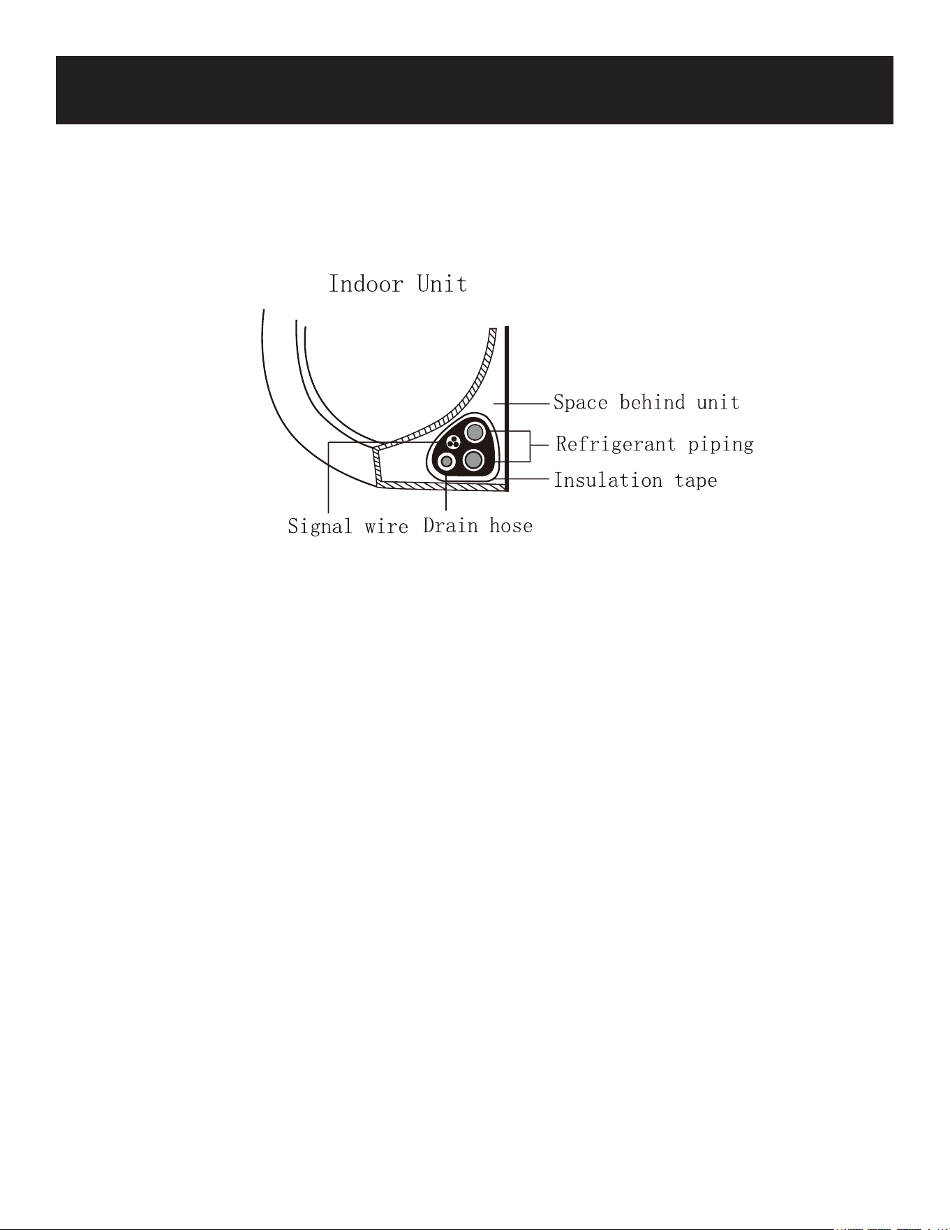
2. Using adhesive vinyl tape, attach the drain hose to the underside of the refrigerant pipes.
3. Using insulation tape, wrap the signal wire
refrigerant pipes, and drain hose tightly
together. Double-check that all items are bundled.
DO NOT WRAP ENDS OF PIPING
When wrapping the bundle, keep the ends of the piping unwrapped. You need to access them
to test for leaks at the end of the installation process (refer to Electrical and Gas Leak Checks
section, Page 30 of this manual).
SET UP & USE
Page 21
SET UP & USE
Step 7: Mount indoor unit
If you installed new connective piping to
the outdoor unit, do the following:
1. If you have already passed the refrigerant
piping through the hole in the wall, skip
#2 & 3, and proceed to #4 below.
2. Otherwise, double-check that the ends of
the refrigerant pipes are sealed to
prevent dirt or foreign materials from
entering the pipes.
3. Slowly pass the wrapped bundle of
refrigerant pipes, drain hose, and signal
wire through the hole in the wall.
4. Hook the top of the indoor unit on the
upper hook of the mounting plate.
5. Check that unit is hooked firmly on
mounting by applying slight pressure to
the left and right-hand sides of the unit.
The unit should not jiggle or shift.
6. Using even pressure, push down on the
bottom half of the unit. Keep pushing
down until the unit snaps onto the hooks
along the bottom of the mounting plate.
7. Again, check that the unit is firmly
mounted by applying slight pressure to
the left and the right-hand sides of the
unit.
If refrigerant piping is already embedded in
the wall, do the following:
1. Hook the top of the indoor unit on the
upper hook of the mounting plate.
2. Use a bracket or wedge to prop up the
unit giving you enough room to connect
the refrigerant piping, signal cable, and
drain hose. (See illustration to the right)
3. Connect drain hose and refrigerant
piping (refer to Refrigerant Piping
Connection section on Page 25 of this
manual for instructions).
4. Keep pipe connection point exposed to
perform the leak test (refer to Electrical
and Gas Leak Checks section, Page 28
of this manual).
5. After the leak test, wrap the connection
point with insulation tape.
6. Remove the bracket or wedge that is
propping up the unit.
7. Using even pressure, push down on the
bottom half of the unit. Keep pushing
down until the unit snaps onto the hooks
along the bottom of the mounting plate.
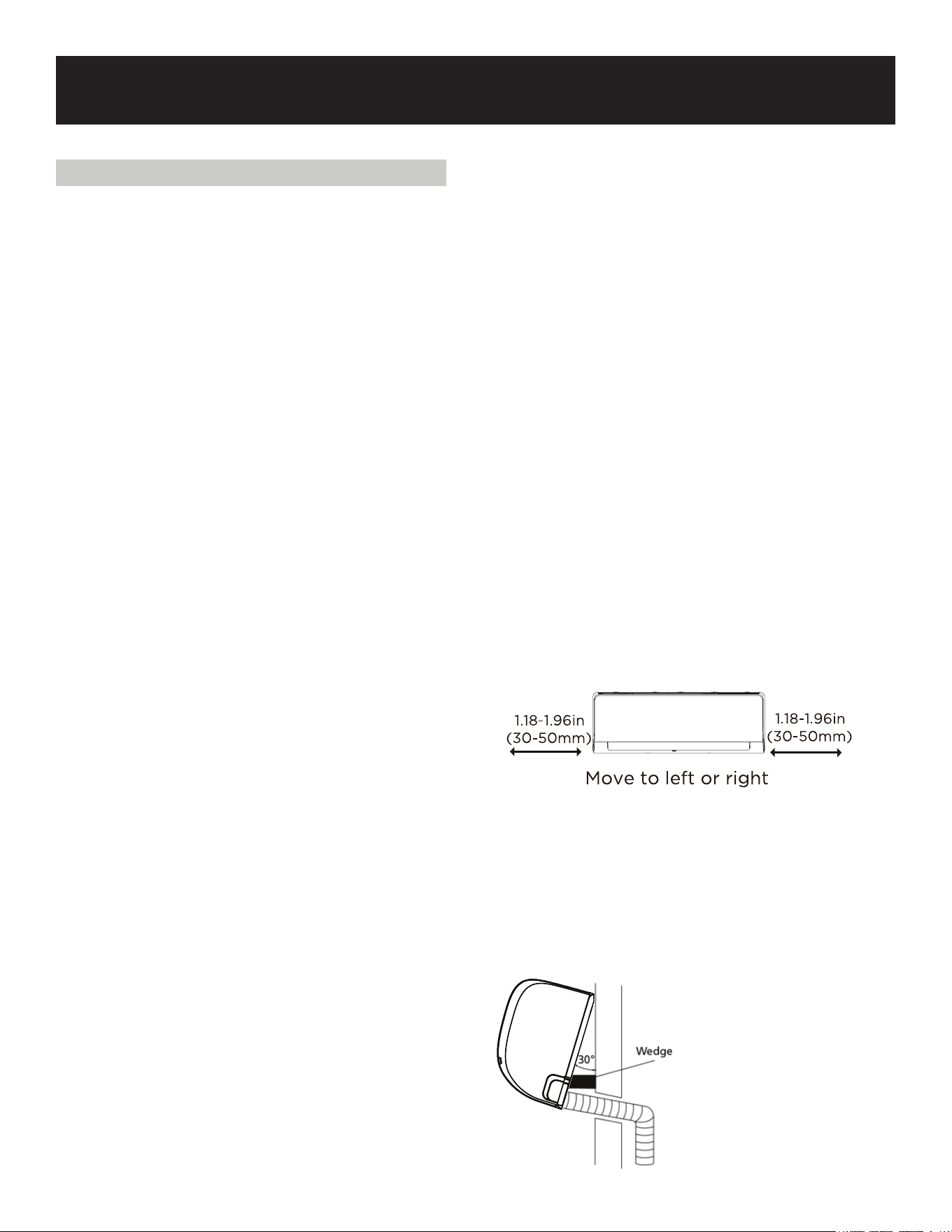
UNIT IS ADJUSTABLE
Keep in mind that the hooks on the mounting
plate are smaller than the holes on the back of the
unit. If you find that you don’t have ample room to
connect embedded pipes to the indoor unit, the
unit can be adjusted left or right by about
1.18”-1.96” (30-50 mm), depending on the model.
Page 22
SET UP & USE
OUTDOOR UNIT INSTALLATION
Install the unit by following local codes and
regulations, there may be dier slightly between
dierent regions.
Installation Instructions - Outdoor unit
Step 1: Select installation location
Before installing the outdoor unit, you must
choose an appropriate location. The following
are standards that will help you choose an
appropriate location for the unit.
Proper installation locations meet the following
standards:
Meets all spatial requirements shown in
Installation Space Requirements above.
Good air circulation and ventilation.
Firm and solid-the location can support the
unit and will not vibrate.
Noise from the unit will not disturb others.
Protected from prolonged periods of direct
sunlight or rain.
Where snowfall is anticipated, take
appropriate measures to prevent ice buildup
and coil damage.
DO NOT install unit in the following
locations:
Near an obstacle that will block air
inlets and outlets.
Near a public street, crowded areas, or
where noise from the unit will disturb
others.
Near animals or plants that will be
harmed by hot air discharge.
Near any source of combustible gas.
In a location that is exposed to large
amounts of dust.
In a location exposed to an excessive
amounts of salty air.
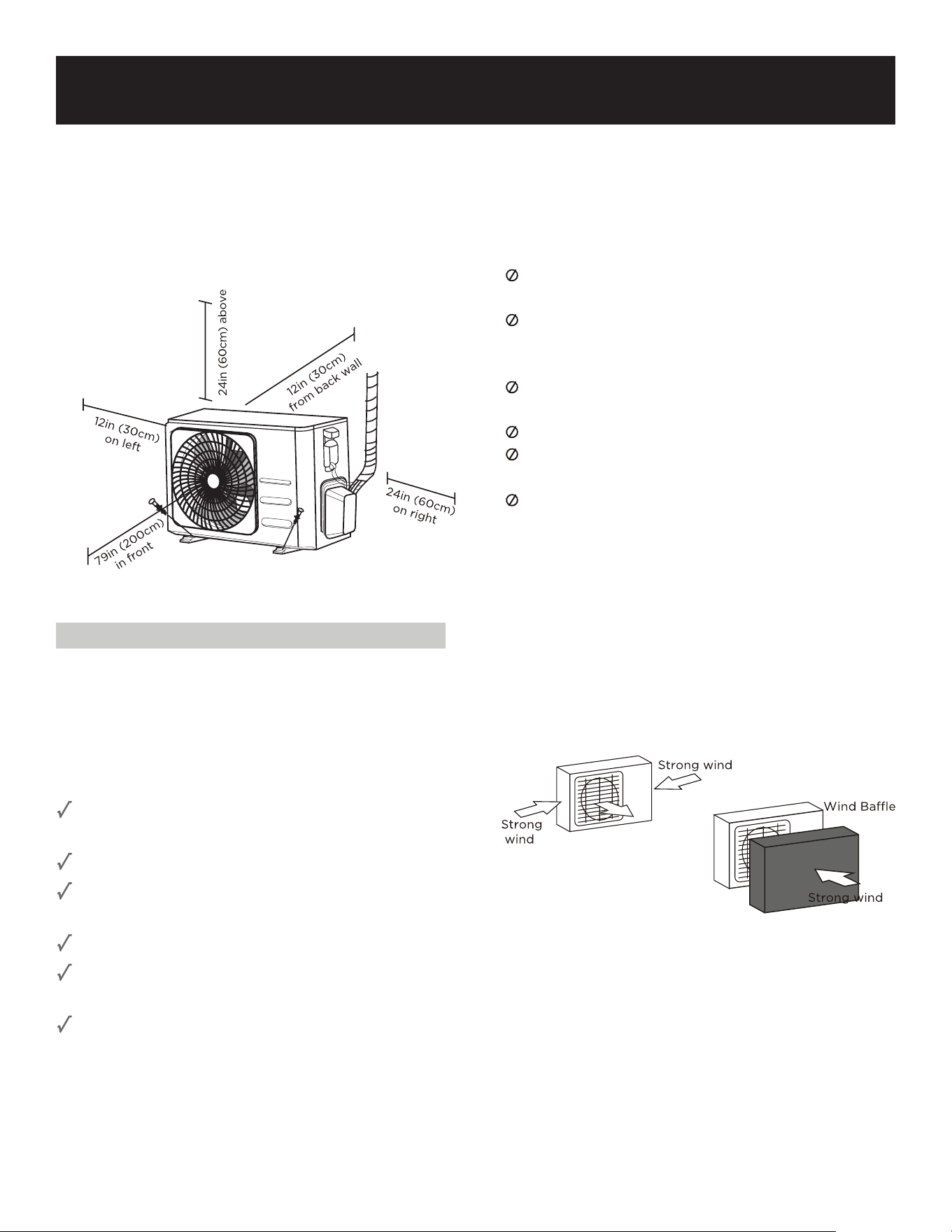
SPECIAL CONSIDERATIONS FOR
EXTREME WEATHER
If the unit is exposed to heavy wind:
Install unit so that air outlet fan is at a
90
o
angle to the direction of the wind. If
needed, build a barrier in front of the unit
to protect it from extremely heavy winds
see figs below.
If the unit is frequently exposed to heavy
rain or snow:
Build a shelter above the unit to protect
it from the rain or snow. Be careful not to
obstruct air flow around the unit.
If the unit is frequently exposed to salty
air (seaside):
Use outdoor unit that is specially
designed to resist corrosion.
Page 23
SET UP & USE
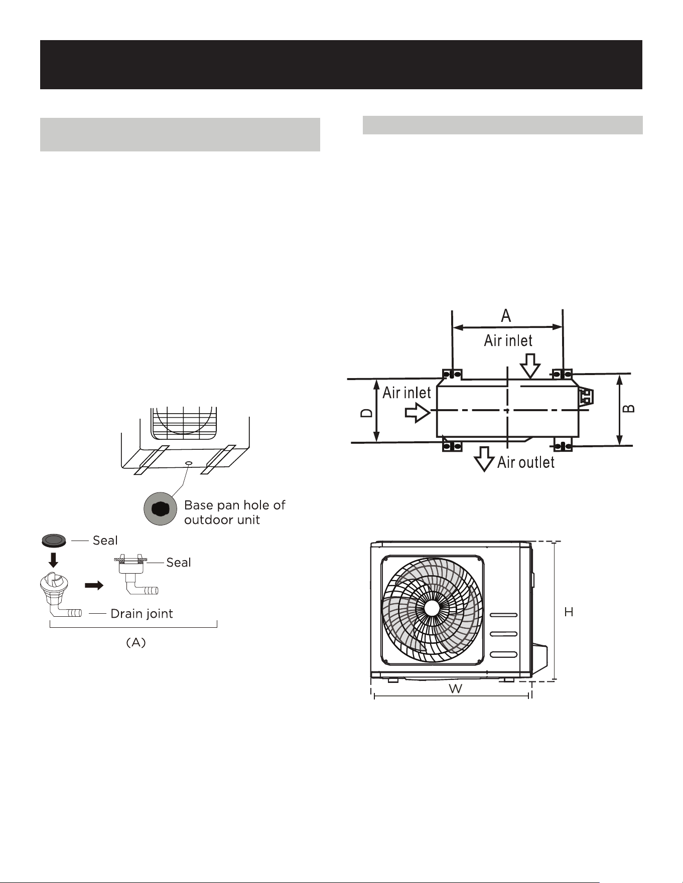
Step 2: Install drain joint (Heat pump unit
only)
Before bolting the outdoor unit in place,
you must install the drain joint at the
bottom of the unit. (see Fig. A)
1. Fit the rubber seal on the end of the
drain joint that will connect to the
outdoor unit.
2. Insert the drain joint into the hole in the
base pan of the unit.
3. Rotate the drain joint 90° until it clicks in
place facing the front of the unit.
4. Connect a drain hose extension (not
included) to the drain joint to redirect
water from the unit during heating
mode.
IN COLD CLIMATES
In cold climates, make sure that the drain
hose is as vertical as possible to ensure
swift water drainage. If water drains too
slowly, it can freeze in the hose and flood
the unit.
Step 3: Anchor outdoor unit
The outdoor unit can be anchored to the
ground or to a wall-mounted bracket with
M10 bolts (not included). Prepare the
installation base of the unit according to the
dimensions below.
UNIT MOUNTING DIMENSIONS
Prepare the installation base of the unit
according to the dimensions below.
21.85”
30.12”
Page 24
SET UP & USE
Step 4: Connect signal and power cables
The outside unit’s terminal block is
protected by an electrical wiring cover on
the side of the unit. A comprehensive wiring
diagram is printed on the inside of the
wiring cover.
WARNING
BEFORE PERFORMING ANY ELECTRICAL
OR WIRING WORK, TURN OFF THE MAIN
POWER TO THE SYSTEM.
1. Prepare the cable for connection:
USE THE RIGHT CABLE
Please choose the right cable refer to Cable
types in page 18.
CHOOSE THE RIGHT CABLE SIZE
Please choose the right cable size
according to the Minimum Circuit Ampacity
indicated on the name plate of the unit.
a. Using wire strippers, strip the rubber
jacket from both ends of cable to reveal
about 1.57” (40mm) of the wires inside.
b. Strip the insulation from the ends of the
wires. Using a wire crimper, crimp u-lugs
on the ends of the wires.
c. Using a wire crimper, crimp u-lugs on the
ends of the wires.
PAY ATTENTION TO LIVE WIRE
While crimping wires, make sure you clearly
distinguish the Live (“L”) Wire from other
wires
WARNING
ALL WIRING WORK MUST BE
PERFORMED STRICTLY IN
ACCORDANCE WITH THE WIRING
DIAGRAM LOCATED INSIDE OF WIRE
COVER OF THE OUTDOOR UNIT.
In North America
1. Remove the wire cover from the unit by
loosening the 3 screws.
2. Dismount caps on the conduit panel.
3. Temporarily mount the conduit tubes
(not included) on the conduit panel.
4. Properly connect both the power supply
and low voltage lines to the
corresponding terminals on the terminal
block.
5. Ground the unit in accordance with local
codes.
6. Be sure to size each wire allowing
several inches longer than the required
length for wiring.
7. Use lock nuts to secure the conduit
tubes.
Page 25
SET UP & USE
Connection Instructions - Refrigerant Piping
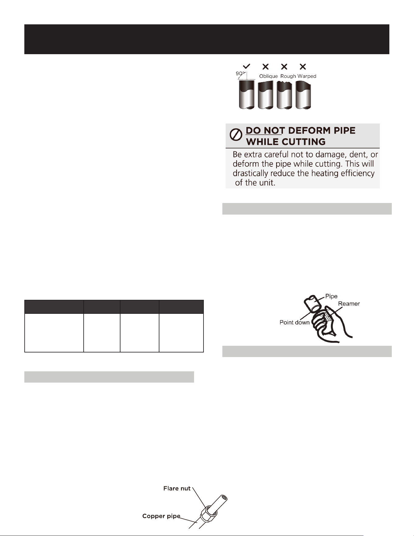
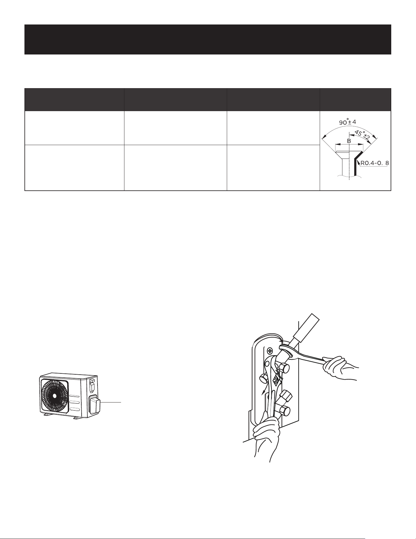
Step 1: Cut pipes
When preparing refrigerant pipes, take extra
care to cut and flare them properly. This will
ensure ecient operation and minimize the
need for future maintenance.
1. Measure the distance between the indoor
and outdoor units.
2. Using a pipe cutter, cut the pipe a little
longer than the measured distance.
3. Make sure that the pipe is cut at a perfect
90° angle.
Step 2: Remove burrs
Burrs can aect the air-tight seal of
refrigerant piping connection. They must
be completely removed.
1. Hold the pipe at a downward angle to
prevent burrs from falling into the pipe.
2. Using a reamer or deburring tool,
remove all burrs from the cut section of
the pipe.
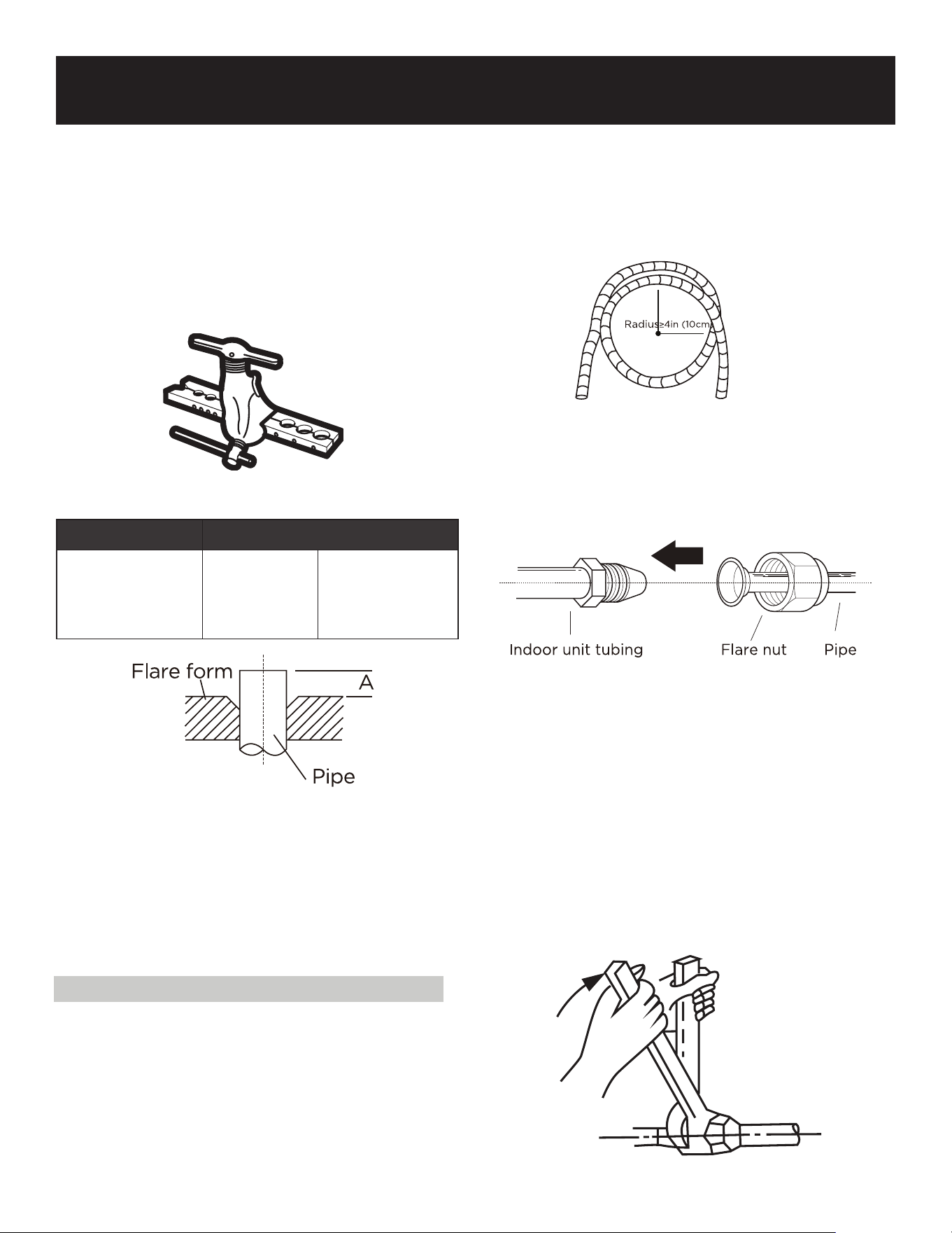
Step 3: Flare pipe ends
Proper flaring is essential to achieve an
airtight seal.
1. After removing burrs from cut pipe,
seal the ends with PVC tape to prevent
foreign materials from entering the
pipe.
2. Sheath the pipe with insulating
material.
3. Place flare nuts on both ends of pipe.
Make sure they are facing in the right
direction, because you can’t put them
on or change their direction after
flaring.
REFRIGERANT PIPING
CONNECTION
When connecting refrigerant piping, do not
let substances or gases other than the
specified refrigerant enter the unit. The
presence of other gases or substances will
lower the unit’s capacity and can cause
abnormally high pressure in the refrigeration
cycle. This can cause explosion and injury.
Note on Pipe Length
The length of refrigerant piping will aect
the performance and energy eciency of
the unit. Nominal eciency is tested on units
with a pipe length of 16.5 feet (5 meters)
North America, the standard pipe length is 25’
(7.5m). A minimum pipe run of 10’ (3 meters)
is required to minimize vibration & excessive
noise.
Maximum Length and Drop Height of
Refrigerant Piping per Unit Model
Model
Capacity
(BTU/h)
Max. Length
(Feet)
Max. Drop
Height (Feet)
R410A,R32 Inverter
Split Air Conditioner
<15,000
82 ft. (25
meters)
33 ft. (10
meters)
Page 26
SET UP & USE
4. Remove PVC tape from ends of pipe
when ready to perform flaring work.
5. Clamp flare form on the end of the
pipe. The end of the pipe must extend
beyond the edge of the flare form in
accordance with the dimensions shown
in the table below.
PIPING EXTENSION BEYOND FLARE FORM
Outer Diameter of
Pipe
A
Min. Max.
Ø .25” (6.35 mm) .275” (.7 mm) .5” (1.3 mm)
6. Place flaring tool onto the form.
7. Turn the handle of the flaring tool
clockwise until the pipe is fully flared.
8. Remove the flaring tool and flare form,
then inspect the end of the pipe for
cracks and even flaring.
Step 4: Connect pipes
When connecting refrigerant pipes, be
careful not to use excessive torque or to
deform the piping in any way. You should
first connect the low-pressure pipe, then the
high-pressure pipe.
MINIMUM BEND RADIUS
When bending connective refrigerant piping,
the minimum bending radius is 4” (10 cm).
Instructions for Connecting Piping to Indoor
Unit
1. Align the center of the two pipes that you
will connect.
2. Tighten the flare nut as tightly as
possible by hand.
3. Using a spanner, grip the nut on the unit
tubing.
4. While firmly gripping the nut on the unit
tubing, use a torque wrench to tighten
the flare nut according to the torque
values in the Torque Requirements table
on Page 25. Loosen the flaring nut
slightly, then tighten again.
Page 27
SET UP & USE
TORQUE REQUIREMENTS
DO NOT USE EXCESSIVE TORQUE
Excessive force can break the nut or damage the refrigerant piping. You must not exceed
torque requirements shown in the table above.
1. Unscrew the cover from the packed
valve on the side of the outdoor unit.
2. Remove protective caps from ends of
valves.
3. Align flared pipe end with each valve,
and tighten the flare nut as tightly as
possible by hand.
4. Using a spanner, grip the body of the
valve. Do not grip the nut that seals the
service valve.
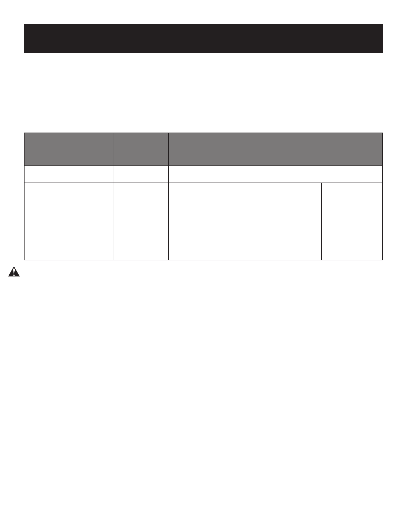
INSTRUCTIONS FOR CONNECTING PIPING TO OUTDOOR UNIT
Outer Diameter of Pipe
Tightening Torque
(N*m)
Flare dimension (B) Flare shape
Ø 0.25” (Ø 6.35 mm) 18~20 (180~200kgf.cm)
0.33” -.34” (8.4-8.7
mm)
Ø 0.5” (Ø 12.7 mm) 49~59 (490~590kgf.cm)
0.64” -.65” (16.2 - 16.5
mm)
Valve cover
5. While firmly gripping the body of the
valve, use a torque wrench to tighten
the flare nut according to the correct
torque values.
6. Loosen the flaring nut slightly, then
tighten again.
7. Repeat steps 3 to 6 for the remaining
pipe.
USE SPANNER TO GRIP MAIN BODY OF
VALVE
Torque from tightening the flare nut can
snap o other parts of valve.
Page 28
SET UP & USE
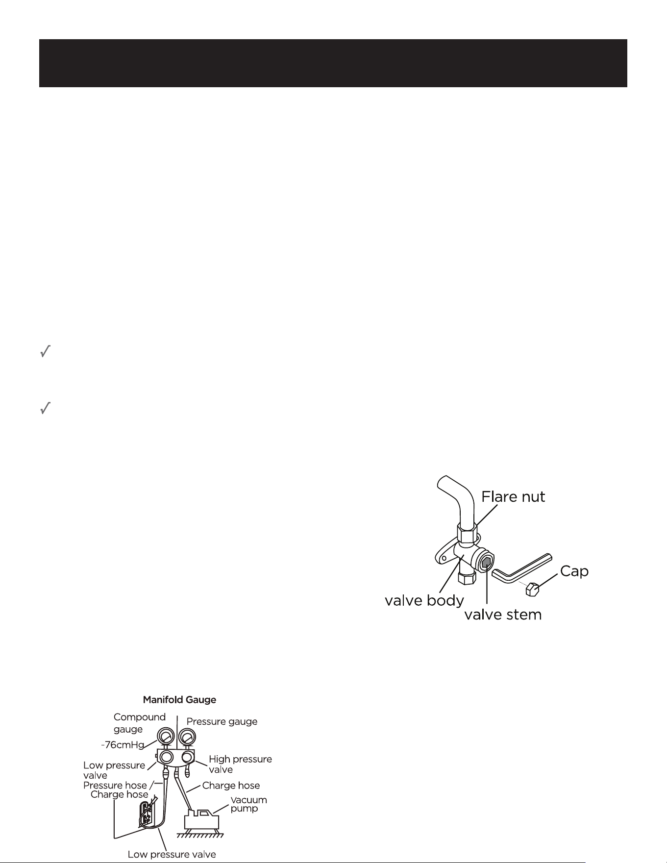
AIR EVACUATION
Preparations and Precautions
Air and foreign matter in the refrigerant
circuit can cause abnormal rises in
pressure, which can damage the air
conditioner, reduce its eciency, and cause
injury. Use a vacuum pump and manifold
gauge to evacuate the refrigerant circuit,
removing any non-condensable gas and
moisture from the system.
Evacuation should be performed upon initial
installation and when unit is relocated.
BEFORE PERFORMING EVACUATION
Check to make sure the connective pipes
between the indoor and outdoor units are
connected properly.
Check to make sure all wiring is connected
properly.
Evacuation Instructions
1. Connect the charge hose of the manifold
gauge to service port on the outdoor
unit’s low pressure valve.
2. Connect another charge hose from the
manifold gauge to the vacuum pump.
3. Open the Low Pressure side of the
manifold gauge. Keep the High Pressure
side closed.
4. Turn on the vacuum pump to evacuate
the system.
5. Run the vacuum for at least 15 minutes,
or until the Compound Meter reads
-76cmHG (-105Pa).
6. Close the Low Pressure side of the
manifold gauge, and turn o the vacuum
pump.
7. Wait for 5 minutes, then check that there
has been no change in system pressure.
8. If there is a change in system pressure,
refer to Gas Leak Check section for
information on how to check for leaks.
If there is no change in system pressure,
unscrew the cap from the packed valve
(high pressure valve).
9. Insert hexagonal wrench into the packed
valve (high pressure valve) and open the
valve by turning the wrench in a 1/4
counterclockwise turn. Listen for gas to
exit the system, then close the valve after
5 seconds.
10. Watch the Pressure Gauge for one minute
to make sure that there is no change in
pressure. The Pressure Gauge should read
slightly higher than atmospheric pressure.
11. Remove the charge hose from the service
port.
12. Using hexagonal wrench, fully open both
the high pressure and low pressure valves.
13. Tighten valve caps on all three valves
(service port, high pressure, low pressure)
by hand. You may tighten it further using
a torque wrench if needed.
OPEN VALVE STEMS GENTLY
When opening valve stems, turn the
hexagonal wrench until it hits against the
stopper. Do not try to force the valve to open
further.
Page 29
SET UP & USE
Note on Adding Refrigerant
Some systems require additional charging depending on pipe lengths. In North America, the
standard pipe length is 15’ (7.5 meters). The refrigerant should be charged from the service port
on the outdoor unit’s low pressure valve. The additional refrigerant to be charged can be
calculated using the following formula.
ADDITIONAL REFRIGERANT PER PIPE LENGTH
Connective Pipe
Length (m)
Air Purging
Method
Additional Refrigerant
≤ Standard pipe length
Vacuum
Pump
N/A
> Standard pipe length
Vacuum
Pump
Liquid Side: Ø 0.25” (Ø 6.35 mm)
R410A:
(Pipe length – standard length) x 0.16 Oz./ft
(Pipe length – standard length) x 30g/meters
Liquid Side:
Ø 0.375”
(Ø 9.52 mm)
CAUTION: DO NOT mix refrigerant types.

Page 30
SET UP & USE
ELECTRICAL AND GAS LEAK
CHECKS
Before Test Run
Only perform test run after you have
completed the following steps:
• Electrical Safety Checks - Confirm that
the unit’s electrical system is safe and
operating properly
• Gas Leak Checks - Check all flare nut
connections and confirm that the system
is not leaking
• Confirm that gas and liquid (high and low
pressure) valves are fully open
Electrical Safety Checks
After installation, confirm that all electrical
wiring is installed in accordance with local
and national regulations, and according to
the Installation Manual.
BEFORE TEST RUN
Check Grounding Work
Measure grounding resistance by visual
detection and with grounding resistance
tester. Grounding resistance must be less
than 0.1Ω.
NOTE: This may not be required for some
locations in North America.
DURING TEST RUN
Check for Electrical Leakage
During the Test Run, use an electro probe
and multimeter to perform a comprehensive
electrical leakage test.
If electrical leakage is detected, turn o the
unit immediately and call a licensed
electrician to find and resolve the cause of
the leakage.
NOTE: This may not be required for some
locations in North America.
WARNING - RISK OF ELECTRIC SHOCK
ALL WIRING MUST COMPLY WITH LOCAL
AND NATIONAL ELECTRICAL CODES, AND
MUST BE INSTALLED BY A LICENSED
ELECTRICIAN.
Gas Leak Checks
There are two dierent methods to check
for gas leaks.
Soap and Water Method
Using a soft brush, apply soapy water or
liquid detergent to all pipe connection
points on the indoor unit and outdoor unit.
The presence of bubbles indicates a leak.
Leak Detector Method
lf using leak detector, refer to the device’s
operation manual for proper usage
instructions.
AFTER PERFORMING GAS LEAK CHECKS
After confirming that all pipe connection
points DO NOT leak, replace the valve
cover on the outside unit.
Page 31
SET UP & USE
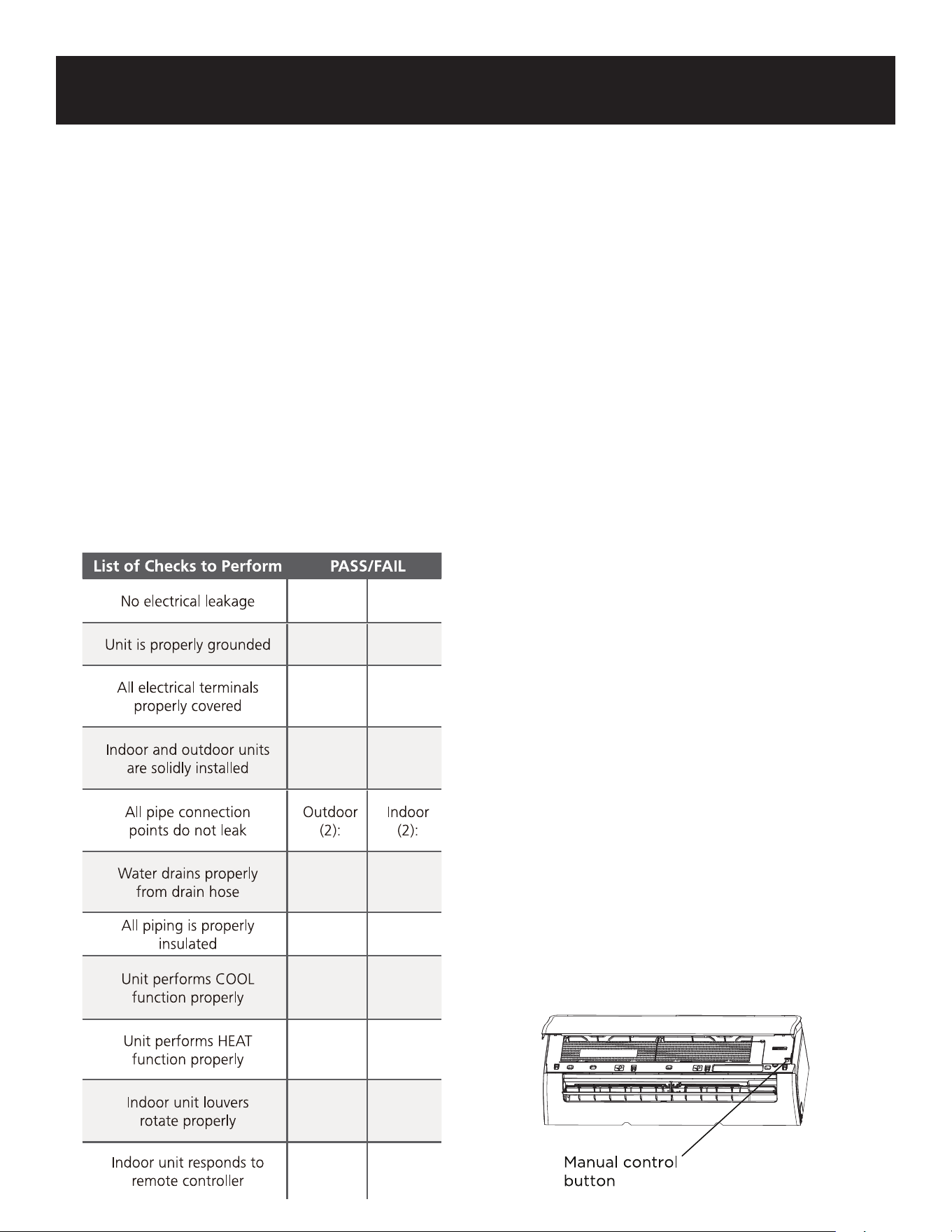
TEST RUN
Test Run Instructions
You should perform the Test Run for at least
30 minutes.
1. Connect power to the unit.
2. Press the ON/OFF button on the remote
control to turn it on.
3. Press the MODE button to scroll through
the following functions, one at a time:
• COOL - Select lowest possible
temperature
• HEAT - Select highest possible
temperature
4. Let each function run for 5 minutes, and
perform the following checks.
DOUBLE-CHECK PIPE CONNECTIONS
During operation, the pressure of the
refrigerant circuit will increase. This may
reveal leaks that were not present during
your initial leak check. Take time during the
Test Run to double-check that all refrigerant
pipe connection points do not have leaks.
Refer to Gas Leak Check section for
instructions.
IF AMBIENT TEMPERATURE IS BELOW
60°F (16°C)
Do not use the remote control to turn on the
COOL function when the ambient
temperature is below 60°F. Use the
MANUAL CONTROL button to test the
COOL function.
1. Lift the front panel of the indoor unit,
and raise it until it clicks in place.
2. The MANUAL CONTROL button is
located on the right-hand side of the
unit. Press it 2 times to select the COOL
function.
3. Perform Test Run as normal.
5. After the Test Run is successfully
completed, and you confirm that all
check points in List of Checks to
perform have PASSED do the
following:
a. Using remote control, return unit to
normal operating temperature.
b. Using insulation tape, wrap the
indoor refrigerant pipe connections
that you left uncovered during the
indoor unit installation process.
Page 32
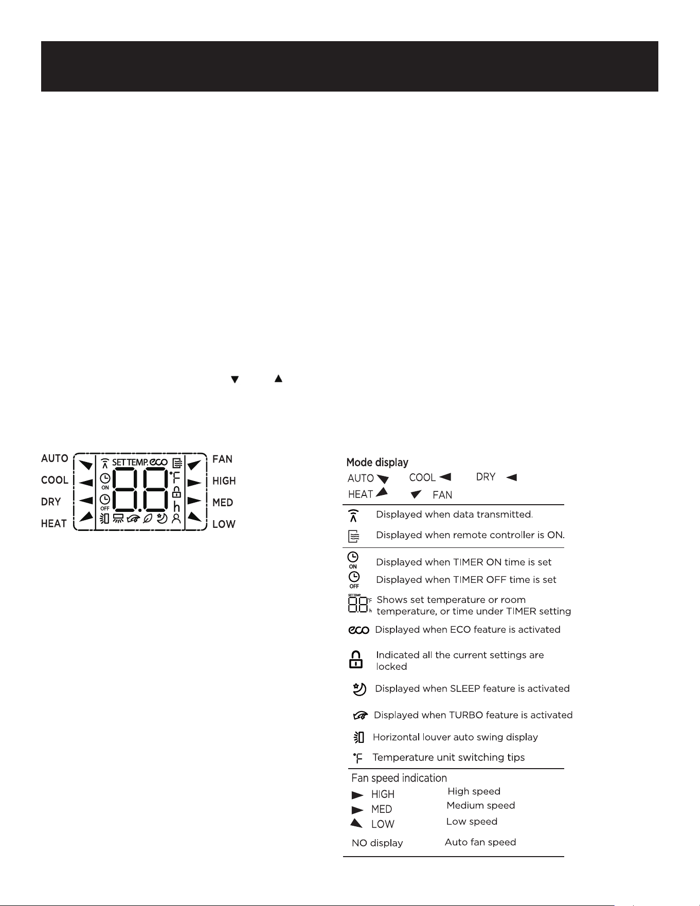
SET UP & USE
Display Code Meanings
Displays temperature, operation feature and error codes:
for 3 seconds when:
• TIMER ON is set (If the unit is OFF, remains on when TIMER ON is set)
• SWING, TURBO, ECO feature is turned on.
for 3 seconds when:
• TIMER OFF is set.
• SWING, TURBO, ECO feature is turned o.
when defrosting.
when Clean feature is turned on.
when unit detects refrigerant leakage.
Indoor unit display
Page 33
SET UP & USE
HANDLING ALKALINE BATTERIES
1. NEVER mix alkaline, standard (carbon-zinc), rechargeable (nickel-cadmium) batteries with
this product.
2. Should fluid from the battery accidentally get into your eyes, there is a threat of loss of
eyesight, do not rub them. Immediately rinse your eyes with clean tap water and then
consult a physician immediately.
3. Do not put the battery in a fire expose it to heat dismantle or modify it. If the insulation or
safety valve is damaged, the battery may leak fluid, overheat or explode.
4. Do not insert the battery with the poles reversed. Doing so may cause some abnormality or
a short and the battery may leak fluid, overheat or explode.
5. Keep the battery out of the reach of children. If the battery is swallowed, contact a physician
immediately.
6. If the alkali fluid gets in your mouth, rinse your mouth with water and contact a physician
immediately.
7. If the alkali fluid gets on your skin or clothes, it may burn your skin, thoroughly rinse the
aected area with tap water. If a chemical burn occurs or if irritation persists, seek medical
attention.
8. Do not mix new and old batteries or other makes of batteries. The dierent attributes may
cause the battery to leak fluid, overheat or explode.
9. This battery was not made to be recharged. Recharging this battery may damage the
insulation or internal structure and may cause the battery to leak fluid, overheat or explode.
10. Do not damage or remove the label on the exterior of the battery. Doing so may cause the
battery to short, leak fluid, overheat or explode.
11. Do not drop, throw or expose the battery to extreme impact. Doing so may cause the
battery to leak fluid, overheat or explode.
12. Do not alter the shape of the battery. If the insulation or safety valve is damaged the battery
may leak fluid, overheat or explode.
13. Immediately remove batteries when they have lost all power. Leaving the batteries in the
unit for a long time may cause the batteries to leak fluid, overheat or explode due to gas
that is generated by the batteries.
14. Remove the batteries from the unit when not using the unit for an extended period of time.
The batteries may leak fluid, overheat or explode due to gas that is generated by the
batteries.
15. Do not apply solder directly to the batteries. The heat may cause the batteries to leak fluid,
overheat or explode.
16. Do not get the batteries wet. Doing so may cause the batteries to overheat.
17. Store batteries someplace out of direct sunlight where the temperature and humidity are
not high. Not doing so may cause the batteries to leak fluid, overheating explode. Also, it
may cause the life and performance of the batteries to decline.
18. Follow the regulations of the local government when disposing of these batteries.
When handling alkaline batteries, basic safety precautions should be followed,
including the following:
SAVE THESE INSTRUCTIONS
HOUSEHOLD USE ONLY
Page 34
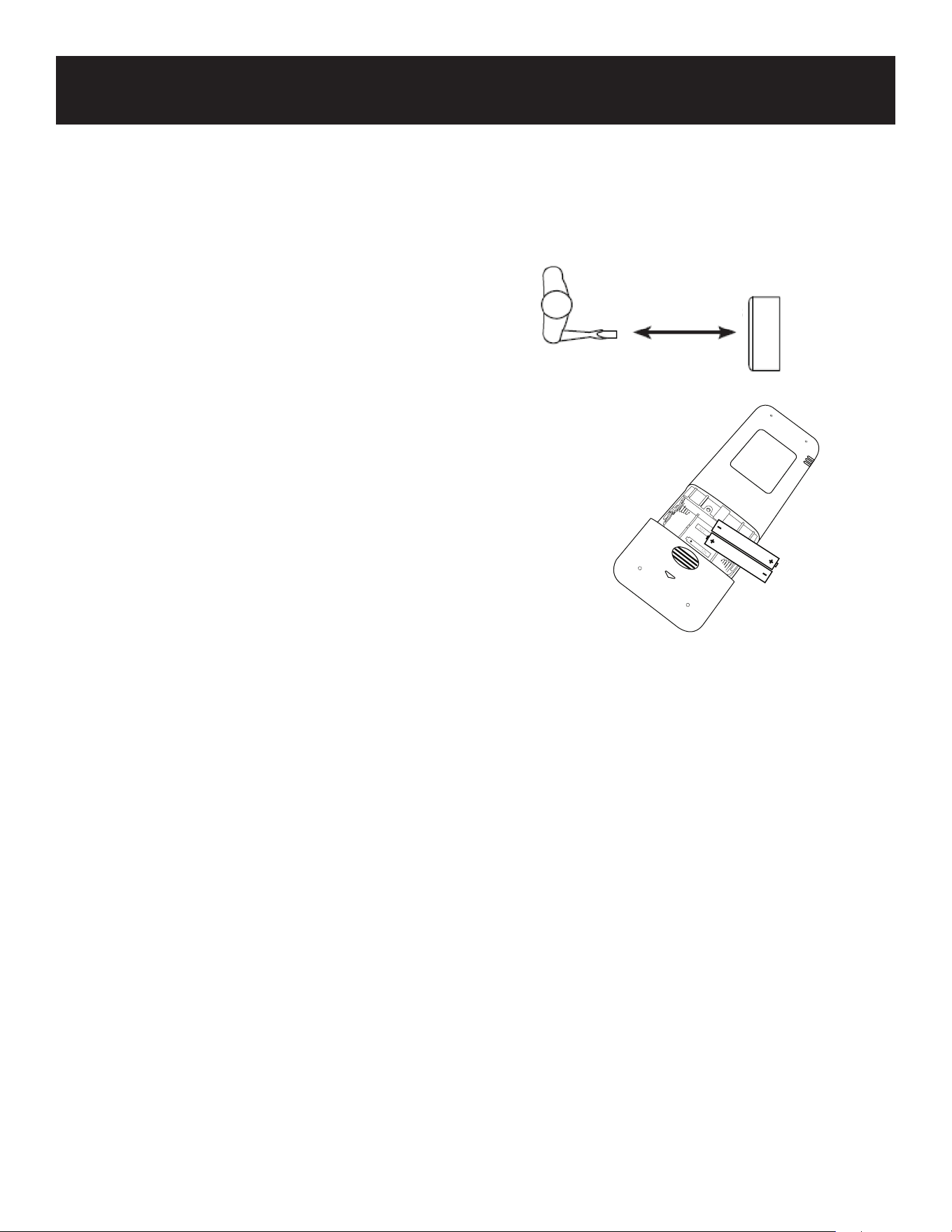
SET UP & USE
CORRECT USE
Point the remote control at the receiver on the appliance, The remote control must be no more
than MAX: 26 Feet (8 Meters) away from the appliance (without obstacle between the remote
control and the receiver).
The remote control must be handled with
extreme care. Do not drop it or expose it to
direct sun light or sources of heat.
BATTERY INSTALLATION (BATTERIES NOT INCLUDED)
1. Slide open the battery compartment cover.
2. Insert 2 x “AAA” batteries as shown below.
3. Slide back the battery cover.
If the remote control unit is replaced or disposed of,
the batteries must be removed and discarded in
accordance with current legislation as they are
harmful to the environment.
MAX: 26 Feet (8 Meters)
Page 35
SET UP & USE
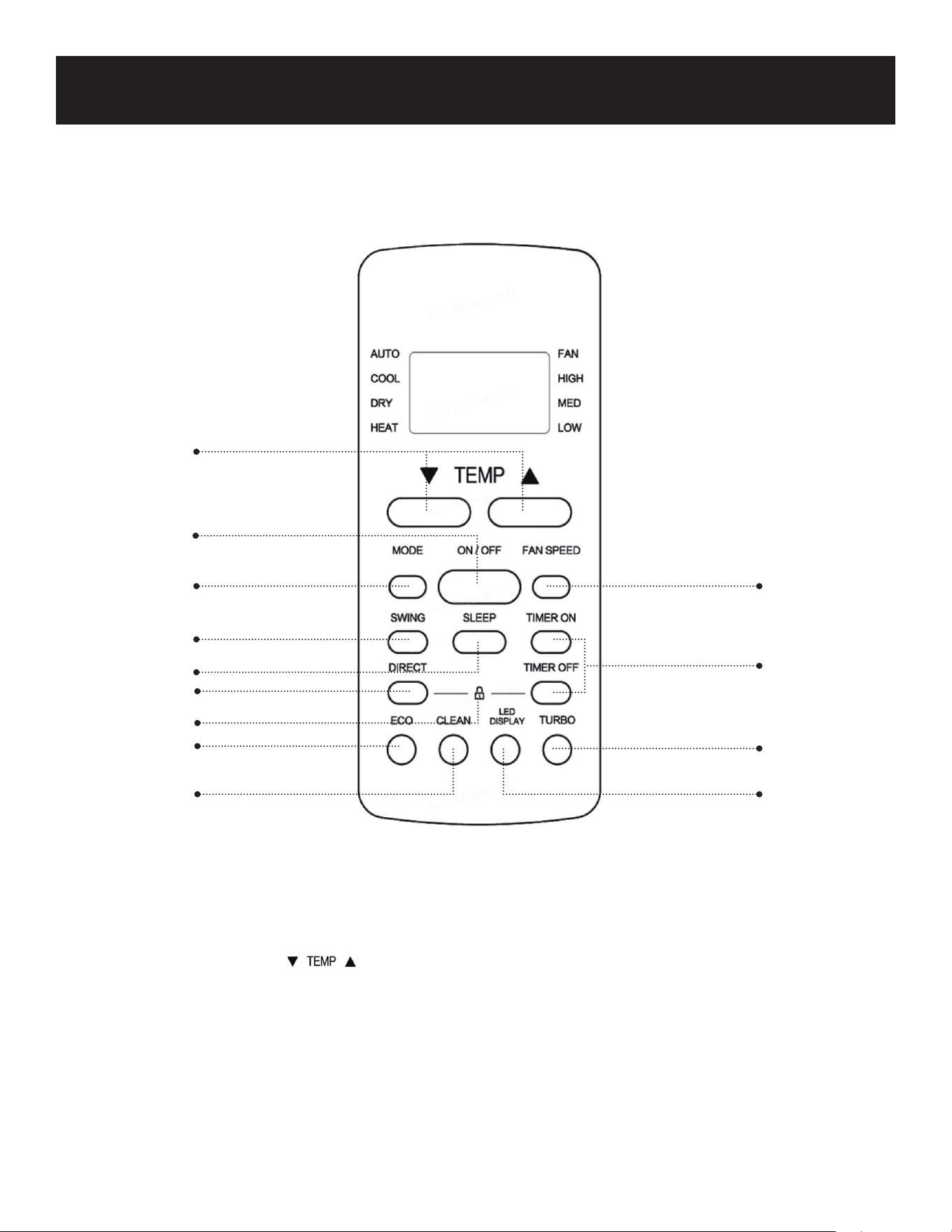
REMOTE CONTROL
1
2
3
5
8
9
10
12
11
13
4
7
6
1. ON/OFF: Press to Turn ON or OFF.
2. Increases temperature in 1°F (1°C) increments. Max. temperature is 86°F (30°C).
Decreases temperature in 1°F (1°C) increments. Min. temperature is 60°F (16°C).
These buttons are also used to set time.
3. MODE: Press to scroll through AUTO, COOL, DRY, HEAT, FAN
4. FAN SPEED: Used to select the HIGH, MED, LOW or AUTO fan speed.
5. SWING: Activates the louver to swing UP/DOWN.
6. SLEEP: Gradually increase the temperature in COOL mode or decrease the temperature in
HEAT mode.
Page 36
SET UP & USE
7. TIMER ON: Set the TIMER for AUTO START.
TIMER OFF: Set the TIMER for AUTO STOP.
8. DIRECT: Adjust the angle of the louvers 6 degrees at a time.
9. ECO: Once the selected temperature has been achieved, the compressor will turn o and
only the fan will work to continue circulating the air in the room.
10. CLEAN: START/STOP the CLEAN function.
11. TURBO: High fan speed brings the unit to set cooling temperature as soon as possible.
12. LOCK: Press DIRECT and TIMER OFF buttons at the same time for 5 seconds to lock the
remote buttons. This can prevent inadvertently making changes to the air
conditioner settings. Press DIRECT and TIMER OFF buttons at the same time for 2
seconds to unlock the keys.
13. LED DISPLAY: Press to turn o the LED Display on the indoor unit.
14. ˚C / ˚F SELECTOR: Press and at the same time for 3 seconds to change temperature
units from Fahrenheit or Celsius.
Information is displayed when the remote controller is powered up.
NOTE: All indicators shown in the figure
are for information only. During
the actual operation, only the
relevant functions are shown on
the LED display.
Page 37
SET UP & USE
ON/OFF: Press to Turn ON or OFF.
Increases temperature in 1°F (1°C) increments. Max. temperature is 86°F (30°C)
Decreases temperature in 1°F (1°C) increments. Min. temperature is 60°F (16°C)
These buttons are also used to set time.
MODE: Press to scroll through AUTO, COOL, DRY, HEAT. FAN
The corresponding symbol will illuminate on the LED display of the remote to indicate
which mode is selected.
AUTO: Select the target temperature 60-86°F (16-30°C) by pressing the buttons until
the desired temperature is displayed on the LED screen of the remote. Unit will
automatically select the COOL or HEAT mode and corresponding fan speed based on
the set temperature.
COOL: Select the target temperature 60-86°F (16-30°C) by pressing the buttons until
the desired temperature is displayed on the LED screen of the remote. Press the Fan
Speed Button to select Low, Medium, High or Auto Speed.
DRY: Ideal for reducing humidity.
Select the target temperature 60-86°F (16-30°C). The fan speed cannot be selected in
this mode.
Keep window and door closed for the best dehumidifying eect.
HEAT: Select the target temperature 60-86°F (16-30°C) by pressing until the desired
temperature is displayed on the LED screen.
Press the Fan Speed Button to select Low, Medium, High or Auto Speed.
FAN: Press the Fan Speed Button to select Low, Medium, High or Auto Speed.
FAN SPEED: Used to select the HIGH, MED, LOW or AUTO fan speed.
SWING: Activates the louver to swing UP/DOWN.
Page 38
SET UP & USE
SLEEP: Gradually increase the temperature in COOL mode or decrease the temperature in
HEAT mode.
The SLEEP function is used to gradually decrease energy use while you sleep and don’t
need the same temperature settings to stay comfortable. This function can only be
activated by the remote control. The SLEEP function is not available in FAN or DRY
mode.
Press the SLEEP button when you are ready to go to sleep.
When in COOL mode, the unit will increase the temperature by 2°F (1°C) after 1 hour,
and will increase an additional 2°F (1°C) after another hour.
When in HEAT mode, the unit will decrease the temperature by 2°F (1°C) after 1 hour,
and will decrease an additional 2°F (1°C) after another hour.
The sleep feature will stop after 8 hours and the unit will continue to operate.
TIMER ON/TIMER OFF
The timer can be used to delay the appliance start up or shutdown, this avoids wasting
electricity by optimizing operating periods.
TIMER ON: The TIMER ON function allows you to set a period of time after which the unit will
automatically turn ON.
Press the buttons to set the start up time from 30 minute increments up to
24 hours.
Point the remote to the indoor unit and wait 1 second. The TIMER ON will be
activated.
TIMER OFF: The TIMER OFF function allows you to set a period of time after which the unit will
automatically turn OFF.
Press the buttons to set the start up time from 30 minute increments up
to 24 hours.
DIRECT: Pressing this button adjusts the angle of the louvers 6 degrees at a time.
ECO: This is an energy saving function that operates in COOL mode.
When the set temperature is below 75°F (24°C) the temperature will automatically adjust
to 75°F (24°C) and the fan speed will change to AUTO.
When the temperature is above 75°F (24°C) the temperature will remain unchanged and
the fan speed will change to AUTO.
Pressing the ECO button again or adjusting the temperature to less than 75°F (24°C) will
stop ECO mode.

Page 39
SET UP & USE
CLEAN: Press CLEAN to activate. This function clears dust when it adheres to the heat
exchanger by automatically freezing and then rapidly thawing the frost. A “pi-pi”
sound will be heard. The CLEAN operation will produce more condensed water and
the cold air will blow out. After cleaning, the internal wind wheel then keeps operating
with hot air to blow-dry the evaporator, thus keeping the inside clean.
NOTE: This is a high temperature cleaning process, and the temperature of the air outlet is very
high. Keep away from the air outlet. The room temperature will also increase during this
time. When this function is activated, the indoor unit display window appears “CL ”. The
process will take approximately 20 to 130 minutes and will turn o automatically.
TURBO: High fan speed brings the unit to set cooling temperature as soon as possible.
LOCK: Press DIRECT and TIMER OFF buttons at the same time for 5 seconds. to lock the
remote buttons. This can prevent inadvertently making changes to the air conditioner
settings. Press DIRECT and TIMER OFF buttons at the same time for 2 seconds to
unlock the keys.
LED DISPLAY: Press to turn o the LED Display on the indoor unit.
°C / ˚F SELECTOR:
Press and at the same time for 3 seconds to change temperature units from Fahrenheit
or Celsius.
OTHER FUNCTIONS:
If the unit loses power, it will automatically restart with the prior settings once power has been
restored.
Page 40
CLEANING & CARE
CLEANING YOUR INDOOR UNIT
BEFORE CLEANING OR MAINTENANCE
ALWAYS TURN OFF YOUR AIR
CONDITIONER SYSTEM AND DISCONNECT
ITS POWER SUPPLY BEFORE CLEANING
OR MAINTENANCE
CAUTION
Only use a soft, dry cloth to wipe the unit
clean. If the unit is especially dirty, you can
use a cloth soaked in warm water to wipe it
clean.
• Do not use chemicals or chemically
treated cloths to clean the unit.
• Do not use benzene, paint thinner,
polishing powder or other solvents to
clean the unit. They can cause the plastic
surface to crack or deform.
• Do not use water hotter than 104°F
(40°C) to clean the front panel. This can
cause the panel to deform or become
discolored.
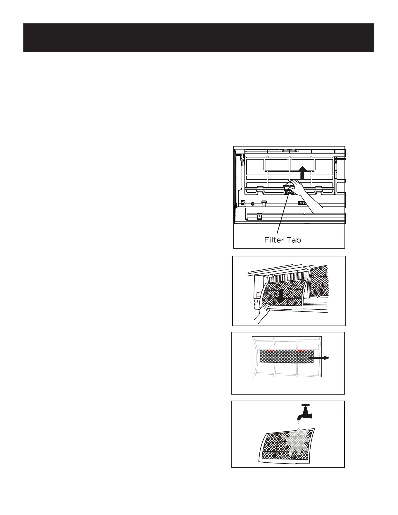
CLEANING YOUR FILTER
A clogged air conditioner can reduce the
cooling eciency of your unit, and can also
be bad for your health. Make sure to clean
the filters once every two weeks.
1. Lift the front panel of the indoor unit.
2. First press the tab on the end of filter to
loosen the buckle, lift it up, then pull it
towards yourself.
3. Now pull the filter out.
4. Detach the small filter from the larger
one. Clean this filter with a hand-held
vacuum.
5. Clean the large air filter with warm, soapy
water. Be sure to use a mild detergent.
6. Rinse the filter with fresh water, then
shake o excess water.
7. Dry it in a cool, dry place, and refrain
from exposing it to direct sunlight.
8. When dry, reattach the air filter to the
larger filter, then slide it back into the
indoor unit.
9. Close the front panel of the indoor unit.
Remove the small air filter, from the
larger one.
Remove
Page 41
CLEANING & CARE
CAUTION
• Before changing the filter or cleaning,
turn o the unit and disconnect its power
supply.
• When removing filter, do not touch metal
parts in the unit. The sharp metal edges
can cut you.
• Do not use water to clean the inside of
the indoor unit. This can destroy
insulation and cause electrical shock.
• Do not expose filter to direct sunlight
when drying. This can shrink the filter.
Maintenance - Long Periods of Non-Use
If you plan not to use your air conditioner for
an extended period of time, do the
following!
Maintenance - Pre-Season Inspection
After long periods of non-use, or before
periods of frequent use, do the following:
CAUTION
• Any maintenance and cleaning of
outdoor unit should be performed by
an authorized dealer or a licensed
service provider.
• Any unit repairs should be performed
by an authorized dealer or a licensed
service provider
Clean all filters
Turn on FAN function until
unit dries out completely
Turn o the unit and
disconnect the power
Remove batteries
from remote control
Check for damaged wires
Check for leaks
Make sure nothing is blocking all air inlets and outlets
Replace batteries
Clean all filters
Page 42
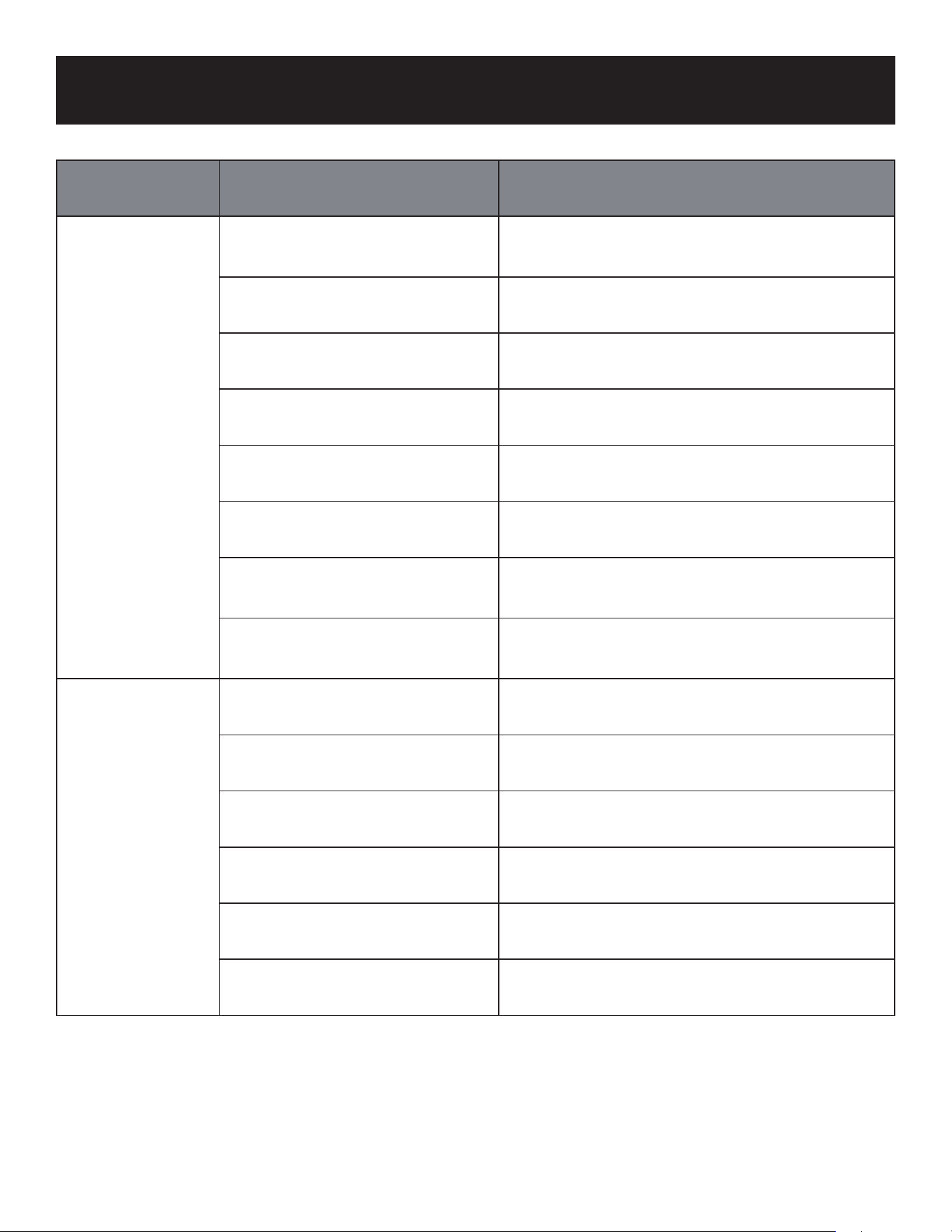
TROUBLESHOOTING & WARRANTY
Problem Cause Solution
Poor Cooling
Performance
Temperature setting may be
higher than ambient room
temperature
Lower the temperature setting
The heat exchanger on the
indoor or outdoor unit is dirty
Clean the aected heat exchanger
The air filter is dirty
Remove the filter and clean it according to
instructions
The air inlet or outlet of either
unit is blocked
Turn the unit o, remove the obstruction
and turn it back on
Doors and windows are open
Make sure that all doors and windows are
closed while operating the unit
Excessive heat is generated by
sunlight
Close windows and curtains during periods
of high heat or bright sunshine
Too many sources of heat in
the room (people, computers,
electronics, etc.)
Reduce amount of heat sources
Low refrigerant due to leak or
long-term use
Have a qualified service technician check
for leaks, re-seal if necessary and top o
refrigerant
The unit is not
working
Power failure Wait for the power to be restored
The power is turned o Turn on the power
The fuse is burned out Replace the fuse
Remote control batteries are
dead
Replace batteries
The Unit’s 3 minutes
protection has been activated
Wait three minutes after restarting the unit
Timer is activated Turn timer o
Page 43
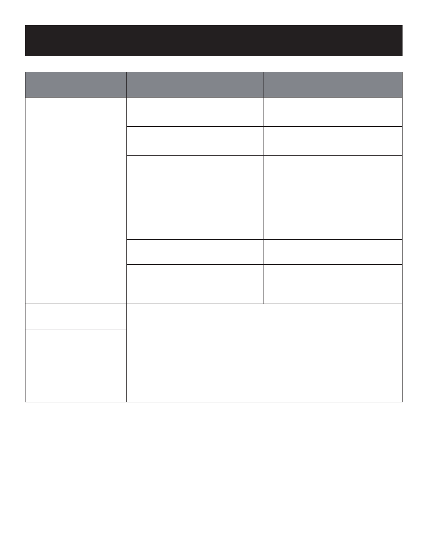
TROUBLESHOOTING & WARRANTY
Problem Cause Solution
The unit starts and stops
frequently
There’s too much or too little
refrigerant in the system
Have a qualified service technician
check for leaks and recharge the
system with refrigerant.
Incompressible gas or moisture
has entered the system.
Have a qualified service technician
evacuate and recharge the system
with refrigerant
The compressor is broken
The compressor may need to be
replaced. Call a qualified service
technician.
The voltage is too high or too
low
Have a qualified service
technician install a manostat to
regulate the voltage
Poor heating
performance
The outdoor temperature is
extremely low
Use auxiliary heating device
Cold air is entering through doors
and windows
Make sure that all doors and
windows are dosed during use
Low refrigerant due to leak or
long-term use
Have a qualified service
technician check for leaks,
re-seal if necessary and top o
refrigerant
Indicator lamps
continue flashing
The unit may stop operation or continue to run safely. If the
indicator lamps continue to flash or error codes appear, wait for
about 10 minutes. The problem may resolve itself. If not, disconnect
the power, then connect it again. Turn the unit on. If the problem
persists, disconnect the power and the BLACK+DECKER Customer
Satisfaction Center at 844-299-0879.
Error code
appears and begins with
the letters as the
following in the window
display of indoor unit:
• E(x). P(x). F(x)
• EH(xX), EL(xx), EC(xx)
• PH(xx), PL(xx), PC(xx)

Page 44
TROUBLESHOOTING & WARRANTY
IF THE AIR CONDITIONER FAILS TO OPERATE:
A) Check to make sure that the air conditioner was installed correctly by a qualied
installer.
B) Check for a blown circuit fuse or a tripped main circuit breaker.
C) Check if electricity to the main power switch of the unit appears to be working.
D) Make sure that both units are in the upright position.
IF NONE OF THE ABOVE SOLVES THE PROBLEM, CONTACT A QUALIFIED
TECHNICIAN.
WARNING: DO NOT TRY TO ADJUST OR REPAIR THE AIR CONDITIONER
YOURSELF.
BEFORE YOU CALL FOR SERVICE
CUSTOMER SERVICE
IMPORTANT
DO NOT RETURN THIS PRODUCT TO THE STORE
If you have a problem with this product, please contact the
W Appliance Co. Customer Satisfaction Center at 844-299-0879 or
DATED PROOF OF PURCHASE, MODEL # AND SERIAL # REQUIRED
FOR WARRANTY SERVICE

Page 45
TROUBLESHOOTING & WARRANTY
LIMITED WARRANTY
Any repair, replacement, or warranty service, and all
questions about this product should be directed to
W Appliance Co. at 844-299-0879 from the USA or Puerto
Rico.
W Appliance Co. warrants to the original purchaser that
the product will be free from defects in material, parts and
workmanship for the period designated for this product. The
warranty commences the day the product is installed and
covers up to a period of 5 years limited compressor/2 years
limited parts (manufacturing defects only). W Appliance Co.
agrees that it will, at its option, replace the defective product
with either a new or remanufactured unit equivalent to your
original purchase during the warranty period.
Exclusions: This warranty does not apply to the
below:
1. If the appearance or exterior of the product has been
damaged or defaced, altered or modied in design or
construction.
2. If the product original serial number has been altered
or removed or cannot be readily determined.
3. If there is damaged due to power line surge, user
damage to the AC power cord or connection to
improper voltage source.
4. If damage is due to general misuse, accidents or acts
of God.
5. If unit was not installed by a licensed technician.
6. If repair attempts are done by unauthorized service
agents, use of parts other than genuine parts or parts
obtained from persons other than authorized service
companies.
7. If the installation was not in compliance with local and
building codes.
8. On units that have been transferred from the original
owner or not located at the original installation
address.
9. On products that have been purchased as
refurbished, like new, second-hand, in a “As-Is” or
“Final Sale” terms.
10. To products used in a commercial or rental setting.
11. To products used in settings other than ordinary
household use or used other than in accordance with
the provided instructions.
12. To damages for service calls for improper
installations.
13. Labor, transportation and shipping costs associated
with the replacement of the unit.
14. Service calls to instruct you how to use your product.
15. Service calls to repair or replace the house fuse, reset
the circuit breaker or correct the wiring in the house.
16. Costs to charge, recharge or dispose of refrigerant.
17. Installation parts or supplies purchased by the
installer or service agent.
REPAIR OR REPLACEMENT AS PROVIDED UNDER
THIS WARRANTY IS THE EXCLUSIVE REMEDY OF THE
CUSTOMER; W APPLIANCE CO. SHALL NOT BE LIABLE
FOR ANY INCIDENTAL OR CONSEQUENTIAL DAMAGES
FOR BREACH OF ANY EXPRESS OR IMPLIED WARRANTY
ON THIS PRODUCT, EXCEPT TO THE EXTENT PROHIBITED
BY APPLICABLE LAW. ANY IMPLIED WARRANTY OF
MERCHANTABILITY OF FITNESS FOR A PARTICULAR
PURPOSE ON THIS PRODUCT IS LIMITED TO THE
DURATION OF THE WARRANTY.
Some states do not allow the exclusion or limitations of
incidental or consequential damages, or limitations on how
long the warranty lasts. In these cases the above exclusions
or limitations may not apply to you. This warranty gives you
specic legal rights and you may also have other rights which
vary from state to state.
Obtaining Service: To obtain service, product literature,
supplies or accessories please call 844-299-0879 to create
a ticket for exchange/repair. Please make sure to provide
receipt and proof of the original installation date, model
number and a brief description of the problem. Our customer
service representative will contact you or send detailed
return instructions.
W Appliance Co. does not warrant that the appliance will
work properly in all environmental conditions, and makes no
warranty and representation, either implied or expressed,
with respect to the quality, performance, merchantability,
or tness for a particular purpose other than the purpose
identied within this user’s manual. W Appliance Co. has
made every effort to ensure that this user’s manual is
accurate and disclaims liability for any inaccuracies or
omissions that may have occurred. Information in this user’s
manual is subject to change without notice and does not
represent a commitment on the part of W Appliance Co..
W Appliance Co. reserves the right to make improvements
to this user’s manual and/or to the products described in
this user’s manual at any time without notice. If you nd
information in this manual that is incorrect, misleading, or
incomplete, please contact us at 844-299-0879.
W Appliance Co.
New York, NY 10018

BLACK & DECKER, BLACK+DECKER, the BLACK & DECKER and
BLACK+DECKER logos and product names are trademarks of The Black &
Decker Corporation, used under license. All rights reserved.
Product in this box may differ slightly from that pictured. Does not affect
function. Not all accessories shown in photography are included in this
package.
Imported by W Appliance, Inc., 1356 Broadway, New York, NY 10018
October 2023 Printed in China
Page 47
MANUAL DE
INSTRUCCIONES
AIRE ACONDICIONADO SPLIT
CON TECNOLOGÍA INVERTER
NÚMERO DE CATÁLOGO
BSA1215MC
¡Gracias por elegir BLACK+DECKER!
POR FAVOR, LEA ESTE MANUAL ANTES DE DEVOLVER ESTE PRODUCTO
POR CUALQUIER MOTIVO.
Si tiene alguna pregunta o experimenta un problema con su compra de
BLACK+DECKER, vaya a www.blackanddecker.com/instantanswers.
Si no puede encontrar la respuesta o no tiene acceso a Internet, llame al 844-299-0879
desde 10:30 a.m. a 6:30 p.m. EST de lunes a viernes para hablar con un agente. Por
favor, tenga el número de catálogo a mano cuando llame.
GUARDE ESTE MANUAL PARA CONSULTARLO NUEVAMENTE MÁS
ADELANTE.

Page 48

Page 49
Gracias por comprar nuestro
producto BLACK+DECKER. Este
manual fácil de usar le guiará para
hacer el mejor uso de su calentador.
Recuerde anotar los números de
modelo y de serie. Están en una
etiqueta en la parte trasera.
Grape o adjunte su recibo de compra a este manual.
Lo necesitará para acceder el servicio de garantía.
Número de modelo
Número de serie
Fecha de compra
CONTENIDO
REGISTRO DEL PRODUCTO
INFORMACIÓN DE SEGURIDAD ............................................................................................... 50-54
CONFIGURACIÓN Y USO
Condiciones de funcionamiento................................................................................................................................55
Piezas y características .......................................................................................................................................... 56-60
Instalación de la unidad interior ..........................................................................................................................61-67
Instalación de la unidad exterior ........................................................................................................................58-70
Conexión de tuberías de refrigerante ............................................................................................................... 71-78
Manejo de pilas alcalinas ....................................................................................................................................... 79-80
Control remoto .............................................................................................................................................................81-85
LIMPIEZA Y CUIDADO ...........................................................................................................................86-89
RESOLUCIÓN DE PROBLEMAS Y GARANTÍA ......................................................... 90-91
Page 50
• Lea este manual de instrucciones antes de instalar y utilizar el aparato.
• Todas las conexiones eléctricas, el cableado y la instalación deben ser realizados por un
profesional autorizado. De lo contrario, podría causar lesiones personales o daños. Las
bombas de calor, los acondicionadores de aire y los equipos de calefacción sólo deben
ser instalados, puestos en marcha y reparados por profesionales y técnicos de servicio
cualificados y autorizados. Los sistemas de aire acondicionado, bombas de calor y
refrigeración son peligrosos debido a los componentes eléctricos de alto voltaje, las altas
presiones de refrigerante y las piezas móviles.
• Este aparato no está diseñado para ser utilizado por niños sin la supervisión de un adulto
responsable. Deben tomarse las debidas precauciones para garantizar la seguridad.
• Desconecte la corriente eléctrica de las unidades interior y exterior antes de realizar cualquier
operación de mantenimiento o limpieza.
• No intente reparar el sistema usted mismo. Las reparaciones incorrectas pueden causar
descargas eléctricas o incendios. Póngase en contacto con un técnico de servicio cualificado
para todas las necesidades de servicio.
• Mantenga los materiales combustibles alejados de la unidad
• NO comparta el circuito eléctrico con otros aparatos. Un suministro eléctrico inadecuado o
insuficiente puede provocar un incendio o una descarga eléctrica.
• Cuando conecte las tuberías del refrigerante, NO deje que entren en la unidad sustancias
o gases distintos del refrigerante. La presencia de otros gases o sustancias disminuirá
la capacidad de la unidad y puede causar una presión anormalmente alta en el ciclo de
funcionamiento. Esto podría causar una explosión y lesiones.
• NO permita que los niños jueguen con el aire acondicionado. Los niños deben ser siempre
supervisados alrededor de la unidad.
• La instalación debe realizarse de acuerdo con las instrucciones de instalación. Una instalación
incorrecta puede causar fugas de agua, descargas eléctricas, incendios o puede anular la
garantía.
ADVERTENCIA
Al utilizar aparatos eléctricos, deben seguirse unas precauciones básicas de seguridad, entre las
que se incluyen las siguientes:
INFORMACIÓN DE SEGURIDAD
PELIGRO
PELIGRO - Amenazas inmediatas
que RESULTARÁN en lesiones
personales graves o la muerte
ADVERTENCIA
ADVERTENCIA - Peligros o
prácticas inseguras que PUEDEN
RESULTAR en lesiones personales
graves o la muerte
PRECAUCIÓN
PRECAUCIÓN - Peligros o prácticas
inseguras que PODRÍAN resultar en
lesiones personales menores
INSTRUCCIONES IMPORTANTES DE SEGURIDAD

Page 51
• En Norteamérica, el servicio o la reparación deben realizarse de acuerdo con los requisitos de
NEC y CEC (únicamente por personal autorizado o por la autoridad competente.) Póngase
en contacto con un técnico de servicio autorizado para la reparación o el mantenimiento de la
unidad.
• Utilice únicamente los accesorios incluidos y las piezas especificadas para la instalación. El uso
de piezas no estándar puede causar fugas de agua, descargas eléctricas o incendios y puede
provocar el fallo de la unidad.
• Para todos los trabajos eléctricos, Conecte los cables firmemente y sujételos con abrazaderas
para evitar que fuerzas externas dañen el terminal. Las conexiones eléctricas inadecuadas
pueden sobrecalentarse y provocar un incendio y/o una descarga eléctrica.
• Todo el cableado debe estar correctamente dispuesto para asegurar que la cubierta del
tablero de control pueda cerrarse correctamente. Si la tapa de la placa de control no se cierra
correctamente, puede producirse corrosión y hacer que los puntos de conexión del terminal se
sobrecalienten, provocando un incendio y/o una descarga eléctrica.
• Este aparato puede ser utilizado por niños a partir de 8 años y por personas con capacidades
físicas, sensoriales o mentales reducidas o con falta de experiencia y conocimientos si han
recibido supervisión o instrucciones sobre el uso del aparato de forma segura y comprenden los
peligros que conlleva. Los niños no deben jugar con el aparato. La limpieza y el mantenimiento
por parte del usuario no deben ser realizados por niños sin supervisión.
GUARDE ESTAS INSTRUCCIONES
USO EXCLUSIVAMENTE DOMÉSTICO
NOTA: Su sistema de aire acondicionado y calefacción y dispositivos relacionados pueden
diferir de las imágenes mostradas en este manual.
INFORMACIÓN DE SEGURIDAD
Page 52
• No introduzca las manos ni ningún objeto en las entradas o salidas de aire. Esto puede
causar lesiones personales o daños a la unidad.
• Al limpiar, tenga cuidado de no salpicar agua sobre la unidad. Si lo hiciera, podría provocar
una descarga eléctrica o dañar la unidad.
• No utilice ni coloque sustancias inflamables, combustibles o nocivas junto a la unidad. En
caso de avería (olor a quemado, etc.), desconecte inmediatamente la corriente eléctrica de
las unidades interior y exterior. Nunca intente reparar el sistema usted mismo; póngase en
contacto con un técnico de servicio cualificado para todas las reparaciones.
• Durante la instalación de las unidades interior y exterior, el acceso a la zona de trabajo
debe estar prohibido a los niños. Pueden producirse accidentes imprevisibles.
• Asegúrese de que la base de la unidad exterior esté bien instalada y estable antes de
utilizarla.
• Compruebe que no pueda entrar aire en el sistema refrigerante y verifique que no haya
fugas de refrigerante al mover el aparato de aire acondicionado.
• No instale el aparato a menos de 50 cm (20”) de sustancias inflamables (alcohol, etc.) o
recipientes a presión (por ejemplo, botes de spray).
• Si el aparato se utiliza en zonas sin posibilidad de ventilación, deben tomarse precauciones
para evitar que cualquier fuga de gas refrigerante permanezca en el ambiente, para evitar
crear un riesgo de incendio.
• Los materiales de empaque son reciclables y deben desecharse en basureros separados. El
propio aire acondicionado debe llevarse a un centro especial de recogida de residuos para
su correcta eliminación.tilice el aire acondicionado sólo como se indica en este manual.
Estas instrucciones no pretenden cubrir todas las condiciones o situaciones posibles.
Como con cualquier aparato eléctrico doméstico, se recomienda siempre sentido común y
precaución para la instalación, funcionamiento y mantenimiento.
• El aparato debe instalarse de acuerdo con NEC y los códigos locales.
• Antes de acceder a los terminales, todos los circuitos de energía deben estar
desconectados de la fuente de energía.
• No intente instalar el aire acondicionado solo; póngase siempre en contacto con personal
cualificado y experimentado.
• La limpieza y el mantenimiento deben ser realizados por una persona o un técnico formado
y con experiencia. Asegúrese de desconectar el aparato de la red eléctrica antes de
proceder a su limpieza o mantenimiento.
• Nunca permanezca expuesto directamente al flujo de aire frío durante períodos
prolongados. La exposición directa y prolongada al aire frío podría ser peligrosa para su
salud.
• Se debe tener especial cuidado en habitaciones donde haya niños, ancianos o personas
enfermas.
PRECAUCIÓN
Por favor, lea las siguientes instrucciones antes de utilizar el equipo.
Normas de seguridad y recomendaciones para el instalador.
INFORMACIÓN DE SEGURIDAD

Page 53
• Si el aparato desprende humo o hay olor a quemado, desconecte inmediatamente la
corriente y póngase en contacto con el Centro de Servicio. El uso prolongado del aparato
después podría provocar un incendio o una electrocución.
• Encargue las reparaciones o el mantenimiento sólo a mecánicos autorizados. Una
reparación incorrecta podría exponer al usuario a riesgos de descarga eléctrica, peligro de
incendio, etc.
• El propio aire acondicionado debe ser llevado a un centro especial de recogida de residuos
para su correcta eliminación.
• Este aparato ha sido fabricado para climatizar ambientes domésticos y no debe ser
utilizado para ningún otro fin, como por ejemplo para secar ropa, enfriar alimentos, etc.
• Utilice siempre el aparato con el filtro de aire montado. El uso del aire acondicionado sin
el filtro de aire podría causar una acumulación excesiva de polvo o residuos en las partes
internas del aparato con posibles averías posteriores.
• El usuario es responsable de que el aparato sea instalado por un instalador mecánico
autorizado.
• Desactive las funciones automáticas si prevé no utilizar el aparato durante un periodo de
tiempo prolongado. La dirección del flujo de aire también debe ajustarse correctamente.
• Compruebe todos los códigos de construcción para conocer los permisos o requisitos de
construcción aplicables.
• Utilice el aire acondicionado sólo como se indica en este manual. Estas instrucciones no
pretenden cubrir todas las condiciones o situaciones posibles.
• Asegúrese de desconectar el aparato de la red eléctrica cuando no vaya a estar en
funcionamiento durante un periodo prolongado y antes de realizar cualquier operación de
limpieza o mantenimiento.
• No utilice extensiones.
• No toque el aparato si está descalzo o con partes del cuerpo mojadas o húmedas.
• No obstruya la entrada o salida de aire de las unidades interior o exterior. La obstrucción
de estas aberturas provoca una reducción de la eficiencia de funcionamiento del aire
acondicionado y puede provocar averías o daños consecuentes.
• No altere de ninguna manera las características del aparato.
• No instale el aparato en ambientes donde el aire pueda contener gas, aceite o azufre o
cerca de fuentes de calor.
• Este aparato no está destinado a ser utilizado por personas [incluidos niños] con
capacidades físicas, sensoriales o mentales reducidas, o con falta de experiencia y
conocimientos, a menos que hayan recibido supervisión o instrucciones sobre el uso del
aparato por parte de una persona responsable de su seguridad.
• No se suba ni coloque objetos pesados o calientes encima de la unidad interior o exterior.
• No deje ventanas o puertas abiertas durante mucho tiempo cuando el aire acondicionado
esté en funcionamiento.
• No dirija el flujo de aire frío hacia plantas o animales. La exposición directa prolongada al
aire frío producido por el aire acondicionado podría tener efectos negativos en plantas y
animales.
• No ponga el aire acondicionado en contacto con agua. El aislamiento eléctrico podría
dañarse y provocar una electrocución.
• No introduzca nunca un palo u objeto similar en el aparato. Este uso indebido puede
provocar lesiones o dañar el funcionamiento del aparato.
• Los niños deben ser supervisados para impedir que jueguen con el aparato.
INFORMACIÓN DE SEGURIDAD

Page 54
• NO instale la unidad en un lugar que pueda estar expuesto a gases combustibles. Si se
acumula gas combustible alrededor de la unidad, puede provocar un incendio.
• NO haga funcionar su aire acondicionado en una habitación húmeda, como un cuarto de
baño o un lavadero. Una exposición excesiva al agua puede provocar un cortocircuito en
los componentes eléctricos.
• NO opere el aire acondicionado con las manos mojadas. Esto puede causar una descarga
eléctrica.
• NO se suba ni coloque objetos encima de la unidad exterior.
• El producto debe estar correctamente conectado a tierra durante la instalación, de lo
contrario podría producirse una descarga eléctrica.
• Instale las tuberías de drenaje de acuerdo con las instrucciones de este manual. Un drenaje
inadecuado puede causar daños por agua a su hogar y a su propiedad.
TENGA EN CUENTA LAS ESPECIFICACIONES DEL FUSIBLE
• La placa de circuito impreso (PCB) del aire acondicionado está diseñada con un fusible para
proporcionar protección contra sobrecorriente.
• Las especificaciones del fusible están impresas en la placa de circuito, tales como: T315AL/250V
AC,T5AL/250VAC,T315A/250VAC,T5A/250VAC,T20A/250VACT30A/250VAC,etc
INFORMACIÓN DE SEGURIDAD

Page 55
CONDICIONES DE FUNCIONAMIENTO
• Si el aire acondicionado funciona fuera de los rangos de temperatura especificados, es posible
que se activen ciertas funciones de protección de seguridad pueden activarse, provocando la
desactivación de la unidad.
• Cuando la temperatura es demasiado alta, el aire acondicionado puede activar el dispositivo
automático de protección, por lo que el aire acondicionado podría apagarse.
• Cuando la temperatura es demasiado baja, el intercambiador de calor del aire acondicionado
puede congelarse, provocando fugas de agua u otras averías.
• En refrigeración o deshumidicación de larga duración con una humedad relativa superior al
80% (puertas y ventanas abiertas), puede producirse condensación de agua o goteo cerca de
la salida de aire.
NOTAS PARA LA CALEFACCIÓN
• El ventilador de la unidad interior no se pondrá en marcha inmediatamente después de poner
en marcha la calefacción para evitar que salga aire frío.
• Cuando hace frío y hay humedad en el exterior, la unidad exterior desarrollará escarcha sobre el
intercambiador de calor, lo que comprometerá la capacidad de calefacción. Es entonces cuando
el aire acondicionado comenzará a descongelarse.
• Durante la descongelación, el aire acondicionado dejará de calentar durante unos 5-12 minutos.
Es posible que salga vapor de la unidad exterior durante el desescarche. Esto no es una avería,
sino el resultado de un desescarche rápido.
• La calefacción se reanudará una vez finalizado el desescarche.
NOTA: Cuando la temperatura exterior es inferior a 32°F (0°C) se recomienda mantener la unidad
enchufada en todo momento para asegurar un funcionamiento continuo sin problemas.
Modo Frío
Exterior 32°F - 122°F (0°C - 50°C)
Interior 60°F - 90°F (16°C - 32°C)
Modo Calor
Exterior 5°F - 75°F (15°C - 24°C)
Interior 32°F - 86°F (0°C - 30°C)
Modo Seco
Exterior 32°F - 122°F (0°C - 50°C)
Interior 50°F - 90°F (10°C - 32°C)
CONFIGURACIÓN Y USO

Page 56
PIEZAS Y CARACTERÍSTICAS
UNIDAD INTERIOR
Rejilla de entrada de aire
Panel
Ventilación
Control remoto
Junta
CONFIGURACIÓN Y USO
Persiana
Placa de montaje
5 tornillos y 5 anclajes
de pared para la placa
de montaje
UNIDAD EXTERIOR
1 filtro grande (no se muestra; dentro de la unidad)
1 filtro pequeño embalado con la unidad interior
Tuerca abocardada de
cobre (2 unidades.)
Rejilla de
salida de aire
Junta de drenaje
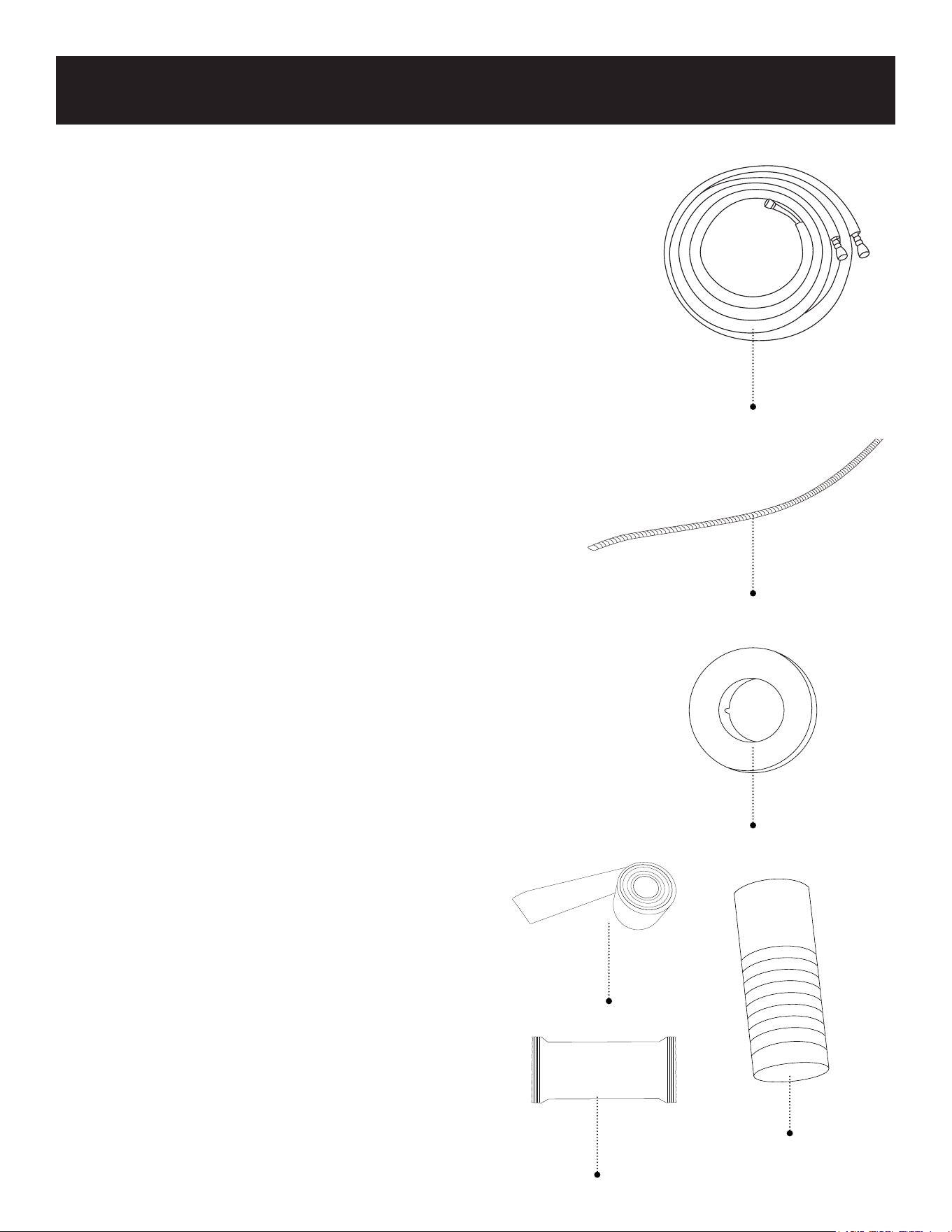
Page 57
CONFIGURACIÓN Y USO
Kits de accesorios:
Los siguientes kits de accesorios de refrigerante
Black + Decker se venden por separado y son
compatibles con BSA1215MC
Modelo Black + Decker: BSAK1
Juego de tuberías de refrigerante de 9,8 pies
(3,8 m) con accesorios abocardados de cobre.
• Línea de líquido de ¼” de diámetro x 9 pies y
10 pulgadas de longitud.
• Línea de succión de ½” de diámetro x 9 pies
10 pulgadas de largo.
Incluye:
• Tubería de drenaje de 16 pies 4.85 pulgadas.
• Tapa del orificio de pared
• Manguito para orificio de pared
• Sellador
• Cinta
Modelo Black + Decker SAK2
Juego de línea de refrigerante de 16,4 pies
(4,85 m) con accesorios abocardados de cobre.
• Línea de líquido de ¼” de diámetro x 16 pies
(4.85 pulgadas) de longitud.
• Línea de succión de ½” de diámetro x 16 pies
(4,85 pulgadas) de longitud.
Incluye:
• Tubería de drenaje de 16 pies 4.85 pulgadas.
• Tapa del orificio de pared
• Manguito para orificio de pared
• Sellador
• Cinta
BSAK3
Juego de tuberías de refrigerante de 24,6 pies
(7,27 m) con accesorios acampanados de cobre.
• Línea de líquido de 1/4” de diámetro x 24 pies
(7,27 pulgadas) de longitud.
• Línea de aspiración de 1/2” de diámetro x 24 pies
(7,27 pulgadas) de longitud.
Incluye:
• Tubería de drenaje de 16 pies 4.85 pulgadas.
• Tapa del orificio de pared
• Manguito para orificio de pared
• Sellador
• Cinta
Tubería de refrigerante
Tubería de drenaje
Tapa del agujero de la pared
Manga del agujero de la pared
Cinta
Sellador

Page 58
CONFIGURACIÓN Y USO
A SUMINISTRAR POR EL INSTALADOR EN FUNCIÓN DEL LUGAR ESPECÍFICO
DE INSTALACIÓN (no incluido con la unidad)
• Tuberías de refrigerante
• Línea de líquido 1/4” (6,35 mm) de diámetro
• Línea de aspiración 1/2” (12,7 mm) de diámetro
• Manguera de drenaje/Drenaje de condensado
• Manguito de orificio de pared
• Sellador
• Suministros de cableado, cinta para envolver, etc.
• Pernos M10 (para fijar la unidad exterior)
HERRAMIENTAS SUGERIDAS PARA LA INSTALACIÓN (No incluidas)
• Llaves ajustables
• Destornillador
• Taladro sacanúcleos
• Cinta métrica
• Taladro eléctrico
• Martillo

Page 59
CONFIGURACIÓN Y USO
ADVERTENCIA: Todas las conexiones eléctricas, el cableado y la instalación deben ser realizados
por un profesional autorizado. La instalación debe realizarse de acuerdo con los
requisitos de las normas locales y nacionales.
PIEZAS DE LA UNIDAD
1. Placa de montaje en pared 2. Panel frontal 3. Persiana
4. Filtros (2 piezas)
1 filtro grande
1 filtro pequeño
5. Tubo de drenaje 6. Cableado eléctrico
7. Tuberías de refrigerante
Línea de líquido de 1/4” de
diámetro
Línea de gas/aspiración de 1/2
8. Control remoto
9. Cable de corriente de la unidad
exterior
Interruptor de corte de aire
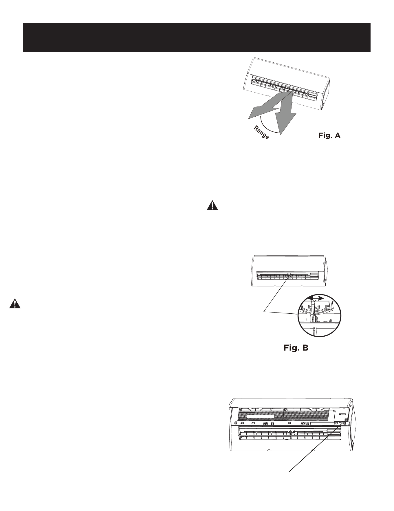
Page 60
CONFIGURACIÓN Y USO
UNIDAD INTERIOR
Ajuste del ángulo del flujo de aire
Ajuste del ángulo vertical del flujo de aire
Con la unidad encendida, utilice el botón SWING/
DIRECT del control remoto para ajustar la dirección
(ángulo vertical) del flujo de aire. Para más detalles,
consulte el manual del control remoto.
NOTA SOBRE LOS ÁNGULOS DE LAS
REJILLAS
Cuando utilice el modo COOL (FRÍO) o DRY (SECO),
no coloque la rejilla en un ángulo demasiado vertical
durante largos periodos de tiempo. Esto puede causar
que el agua se condense en la lama de la rejilla, que
caerá sobre su suelo o mobiliario.
Cuando utilice el modo COOL (FRÍO) o HEAT (CALOR),
si coloca la rejilla en un ángulo demasiado pequeño
puede reducir el rendimiento de la unidad debido a la
restricción del flujo de aire.
Ajuste del ángulo horizontal del flujo de aire
El ángulo horizontal del flujo de aire debe ajustarse
manualmente.
Sujete la varilla deflectora (véase la Fig. B) y ajústela
manualmente en la dirección que prefiera.
El botón DIRECT del control remoto ajustará el ángulo
de las rejillas 6 grados cada vez.
Funcionamiento manual (sin control remoto)
PRECAUCIÓN
El botón manual sólo está previsto para pruebas y
operaciones de emergencia. No utilice esta función a
menos que haya perdido el control remoto y sea
absolutamente necesario. Para restablecer el
funcionamiento normal, utilice el control remoto para
activar la unidad. La unidad debe estar apagada antes
de la operación manual.
Para operar su unidad manualmente:
1. Abra el panel frontal de la unidad interior.
2. Localice el botón MANUAL CONTROL (CONTROL
MANUAL) en el lado derecho de la unidad.
3. Pulse el botón MANUAL CONTROL (CONTROL
MANUAL) una vez para activar el modo FORCED
AUTO (AUTO FORZADO).
4. Pulse de nuevo el botón MANUAL CONTROL
(CONTROL MANUAL) para activar el modo
FORCED COOLING (ENFRIAMIENTO FORZADO).
5. Pulse el botón MANUAL CONTROL (CONTROL
MANUAL) una tercera vez para apagar la unidad.
6. Cierre el panel frontal.
NOTA: No mueva la rejilla con la mano.
Esto hará que la rejilla no esté
sincronizada. Si esto ocurre, apague la
unidad y desconéctela durante unos
segundos, luego reinicie la unidad. Esto
restablecerá la rejilla.
PRECAUCIÓN: No coloque los dedos
dentro o cerca del lado del soplador y de
succión de la unidad. El ventilador de alta
velocidad dentro de la unidad puede
causar lesiones.
Varilla deflectora
Botón de control
manual
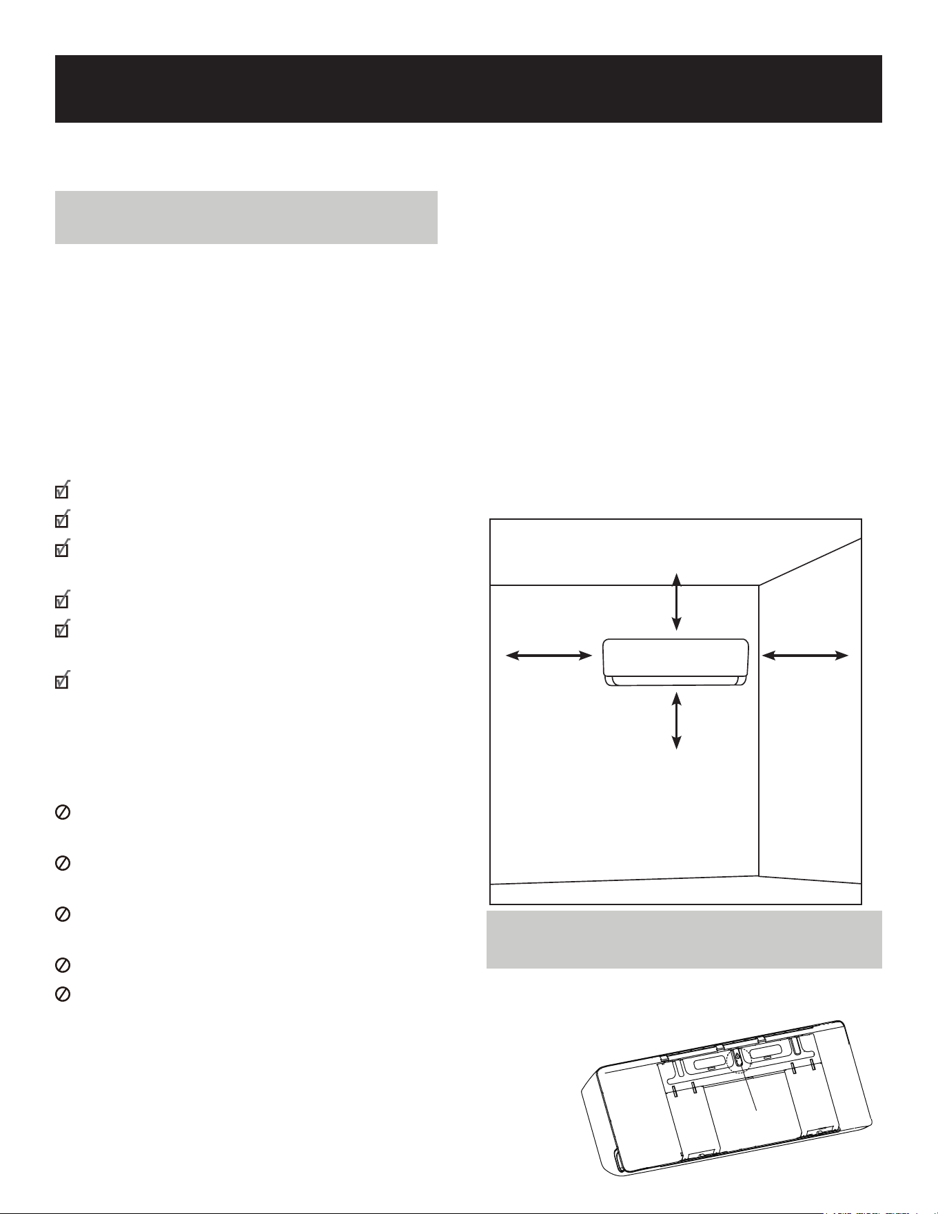
Page 61
Espacio mínimo hasta el techo 5,9
pulgadas (15 cm)
Espacio mínimo a
la pared adyacente
4,75 pulgadas
(12 cm)
Espacio mínimo a
la pared adyacente
4,75 pulgadas
(12 cm)
Espacio mínimo hasta el
suelo 78,7 pulgadas
CONFIGURACIÓN Y USO
INSTALACIÓN DE LA UNIDAD INTERIOR
Instrucciones de instalación - Unidad
interior
Paso 1: Seleccione el lugar de
instalación
Antes de instalar la unidad interior, debe
elegir una ubicación adecuada. Las
siguientes son normas que le ayudarán a
elegir una ubicación adecuada para la
unidad.
Las ubicaciones de instalación adecuadas
cumplen las siguientes normas:
Buena circulación de aire
Drenaje conveniente
El ruido de la unidad no molestará a
otras personas
Firme y sólida-la ubicación no vibrará
Suficientemente resistente para soportar
el peso de la unidad
Un lugar alejado al menos un metro de
otros aparatos eléctricos (por ejemplo,
TV, radio, computadora).
NO instale la unidad en los siguientes
lugares:
Cerca de cualquier fuente de calor, vapor
o gas combustible
Cerca de artículos inflamables como
cortinas o ropa
Cerca de cualquier obstáculo que pueda
bloquear la circulación del aire
Cerca de la puerta
En un lugar expuesto a la luz solar directa
NOTA SOBRE EL ORIFICIO DE LA PARED:
Si no hay tuberías de refrigerante:
Al elegir la ubicación, tenga en cuenta que
debe dejar espacio suficiente para un orificio
en la pared (consulte el paso Perforar un
orificio en la pared para las tuberías de
conexión) para el cable de señal y las
tuberías de refrigerante que conectan las
unidades interior y exterior. La posición
predeterminada para todas las tuberías es el
lado derecho de la unidad interior (mirando
hacia la unidad). Sin embargo, la unidad puede
alojar tuberías tanto a la izquierda como a la
derecha. Consulte el siguiente diagrama para
comprobar la distancia adecuada a las paredes
y al techo:
Paso 2: Fije la placa de montaje a la
pared
• Retire el tornillo que sujeta la placa de
montaje a la parte posterior de la unidad
interior.
Tornillo
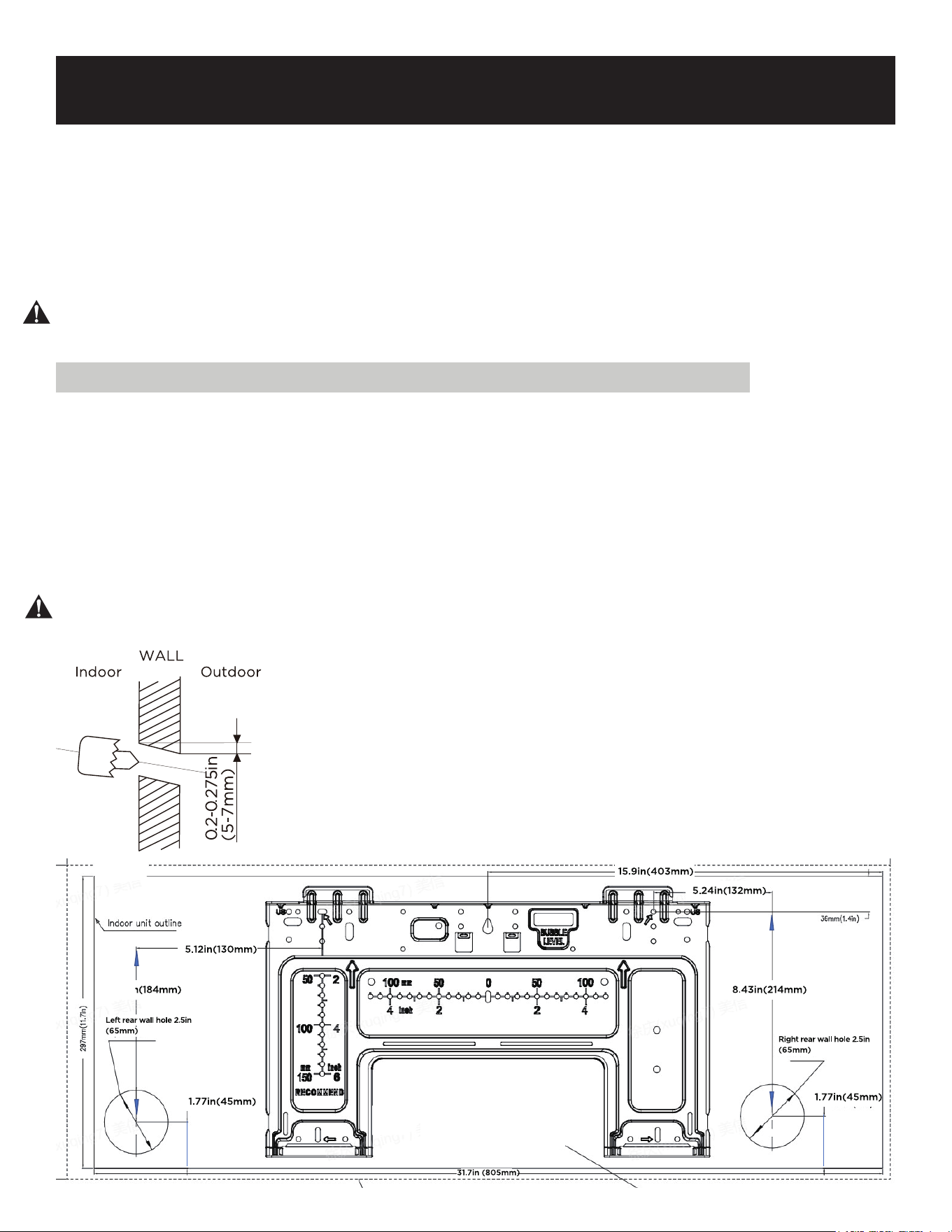
Page 62
CONFIGURACIÓN Y USO
• Fije la placa de montaje a la pared con los tornillos suministrados. Compruebe que la placa
de montaje está plana contra la pared. Los tornillos deben fijarse en los montantes de la
pared.
NOTA PARA PAREDES DE HORMIGÓN O LADRILLO:
Si la pared es de ladrillo, hormigón o material similar, taladre orificios de 0,2” (5 mm) de
diámetro en la pared e inserte los anclajes de pared suministrados. A continuación, fije la placa
de montaje a la pared apretando los tornillos directamente en los anclajes de pared.
ADVERTENCIA: Será necesario utilizar tornillos adecuados para el tipo específico de pared
para anclar correctamente el aire acondicionado.
Paso 3: Taladrar el orificio de la pared para la tubería de conexión
1. Determine la ubicación del orificio en la pared basándose en la posición de la placa de
montaje. Consulte Dimensiones de la placa de montaje.
2. Con una broca de 65 mm (2,5”), taladre un orificio en la pared. Compruebe que el orificio
está taladrado con un ligero ángulo hacia abajo, de forma que el extremo exterior del
orificio esté más bajo que el interior en aproximadamente 0,2-0,275” (5mm a 7mm). Esto
asegurará un drenaje adecuado del agua.
3. Coloque el manguito protector de pared en el orificio. Esto protege los bordes del agujero y
ayudará a sellarlo cuando termine el proceso de instalación.
PRECAUCIÓN: Compruebe que no hay tuberías ni cables detrás de la pared antes de taladrar o
cortar el orificio.
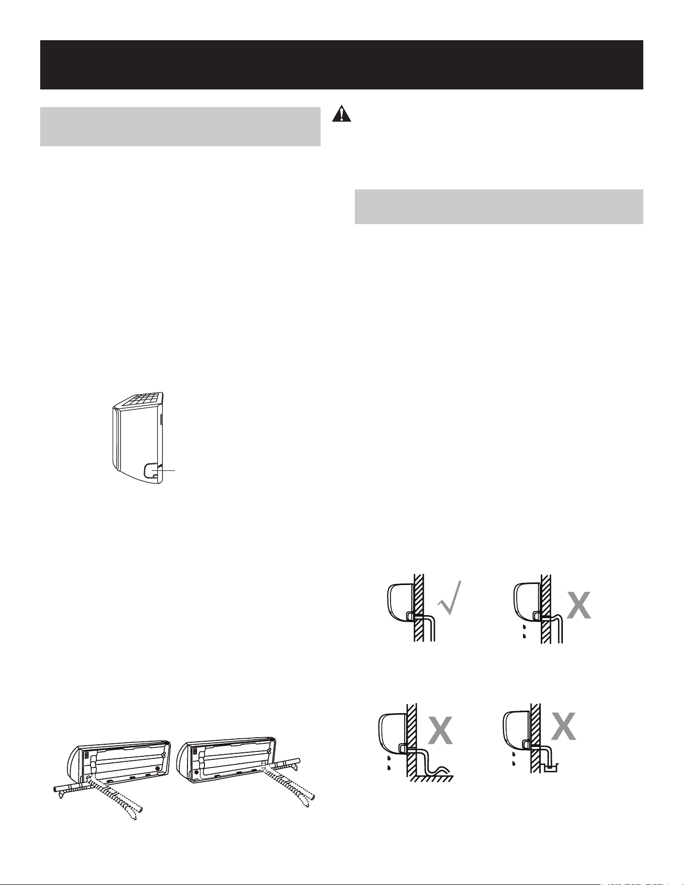
Page 63
CONFIGURACIÓN Y USO
Paso 4: Prepare la tubería de
refrigerante
La tubería de refrigerante está dentro de un
manguito aislante fijado a la parte posterior de la
unidad. Debe preparar la tubería antes de pasarla
por el orificio de la pared.
1. Based on the position of the wall hole relative
to the mounting plate, choose the side from
which the piping will exit the unit.
2. If the wall hole is behind the unit, keep the
knock-out panel in place. If the wall hole is to
the side of the indoor unit, remove the plastic
knock-out panel from that side of the unit.
This will create a slot through which your
piping can exit the unit. Use needle nose
pliers if the plastic panel is too dicult to
remove by hand.
3. Si la tubería de conexión existente ya está
empotrada en la pared, proceda directamente
al paso Conectar la manguera de drenaje. Si
no hay tubería empotrada, conecte la tubería
de refrigerante de la unidad interior a la
tubería de conexión que unirá las unidades
interior y exterior. Consulte la sección
Conexión de la tubería de refrigerante de
este manual para obtener instrucciones
detalladas.
NOTA PARA EL ÁNGULO DE LAS TUBERÍAS
Las tuberías de refrigerante pueden salir de la
unidad interior desde cuatro ángulos diferentes:
Lado izquierdo, Lado derecho, Parte trasera
izquierda, Parte trasera derecha.
PRECAUCIÓN
Tenga mucho cuidado de no deformar o dañar
las tuberías al doblarlas para alejarlas de la
unidad. Cualquier deformación en las tuberías
afectará al funcionamiento de la unidad.
Paso 5: Conecte la manguera de
drenaje
Para garantizar un drenaje adecuado, conecte
una manguera de drenaje en el mismo lado en el
que la tubería de refrigerante sale de la unidad.
Conecte la extensión de la manguera de
drenaje (se adquiere por separado) al extremo de
la manguera de drenaje.
• Envuelva firmemente el punto de conexión
con cinta de teflón para garantizar un buen
sellado y evitar fugas.
• Para la parte de la manguera de drenaje que
permanecerá en el interior, envuélvala con
espuma aislante de tuberías para evitar la
condensación.
• Retire el filtro de aire y vierta una pequeña
cantidad de agua en la bandeja de drenaje
para asegurarse de que el agua sale de la
unidad sin problemas.
NOTA SOBRE LA INSTALACIÓN DE LA
MANGUERA DE DRENAJE
Asegúrese de colocar la manguera de drenaje de
acuerdo con las siguientes figuras.
Knock-out Panel
CORRECTO
INCORRECTO
INCORRECTO
INCORRECTO
Asegúrese de que no haya
dobleces ni abolladuras en la
manguera de drenaje para
garantizar un drenaje correcto.
Los dobleces en la manguera de
drenaje crearán trampas de agua.
Los dobleces en la
manguera de drenaje
crearán trampas de agua.
No coloque el extremo de la
manguera de drenaje en agua
ni en recipientes que acumulen
agua. Esto impedirá un drenaje
adecuado.
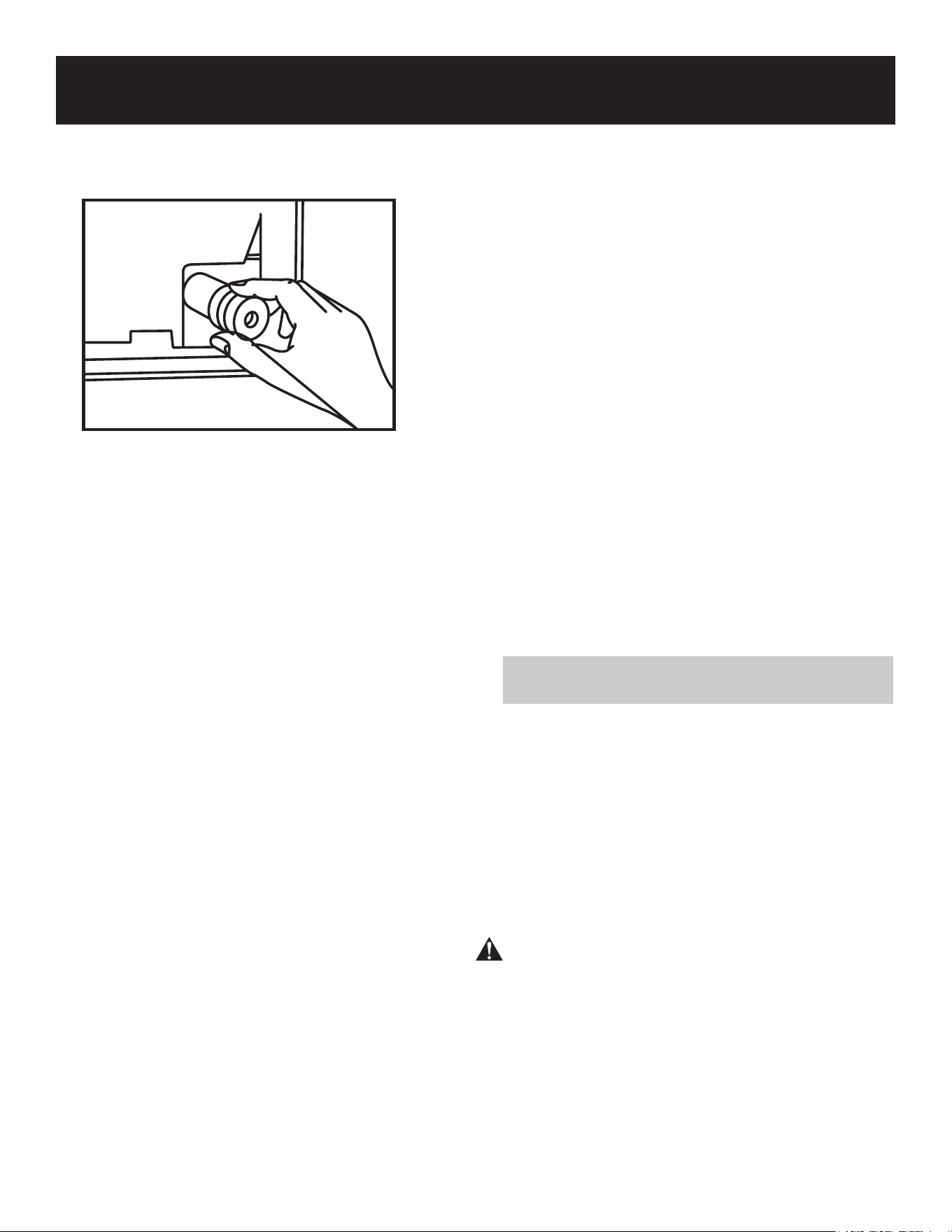
Page 64
CONFIGURACIÓN Y USO
TAPE EL AGUJERO DE DRENAJE NO
UTILIZADO
Para evitar fugas no deseadas, debe tapar el
orificio de drenaje no utilizado con el tapón
de goma incluido.
ANTES DE REALIZAR CUALQUIER
TRABAJO ELÉCTRICO LEA ESTAS
NORMAS
1. Todo el cableado debe cumplir con los
códigos eléctricos locales y nacionales,
regulaciones y debe ser instalado por un
electricista con licencia.
2. Todas las conexiones eléctricas deben
realizarse de acuerdo con el Diagrama de
Conexión Eléctrica ubicado en los paneles
de las unidades interior y exterior.
3. Si hay algún problema de seguridad con el
suministro eléctrico, deje de trabajar
inmediatamente. No instale la unidad hasta
que el problema de seguridad esté
debidamente resuelto.
4. La tensión de la corriente debe estar
dentro del 90-110% de la tensión nominal.
Una fuente de corriente insuficiente puede
causar fallos de funcionamiento, descargas
eléctricas o incendios.
5. Si se conecta la corriente al cableado fijo,
debe instalarse un protector contra
sobretensiones y un interruptor de corriente
principal.
6. Si conecta la corriente al cableado fijo, debe
incorporar un interruptor o disyuntor que
desconecte todos los polos y tenga una
separación de contactos de al menos 3 mm
(1/8 pulgadas.) en el cableado fijo. El
técnico cualificado debe utilizar un
disyuntor o interruptor aprobado.
7. Conecte la unidad únicamente a una toma
de circuito derivado individual. No conecte
ningún otro aparato a esa toma.
8. Asegúrese de conectar correctamente a
tierra el aire acondicionado.
9. Todos los cables deben estar firmemente
conectados. Un cableado suelto puede hacer
que el terminal se sobrecaliente, provocando
un mal funcionamiento del producto y un
posible incendio.
10. No deje que los cables toquen o descansen
contra la tubería de refrigerante, el
compresor o cualquier parte móvil dentro de
la unidad.
11. Si la unidad tiene un calentador eléctrico
auxiliar, debe instalarse a una distancia
mínima de 1 metro (40 pulgadas) de
cualquier material combustible.
12. Para evitar descargas eléctricas, no toque
nunca los componentes eléctricos poco
después de desconectar la corriente.
Después de desconectar la corriente, espere
siempre 10 minutos o más antes de tocar los
componentes eléctricos.
PASO 6: CONECTE LOS CABLES DE SEÑAL
Y DE CORRIENTE
El cable de señal permite la comunicación
entre las unidades interior y exterior.
Primero debe elegir el tamaño correcto del
cable antes de prepararlo para la conexión.
ELIJA EL TAMAÑO DE CABLE CORRECTO
NOTA: Elija el tamaño de cable correcto de
acuerdo con los amperios de circuito
mínimos indicados en la etiqueta de
clasificación de la unidad.
ADVERTENCIA
Todo el cableado debe realizarse
estrictamente de acuerdo con el diagrama
de cableado situado en la parte posterior
del panel frontal de la unidad interior.
Consulte el diagrama de cableado en la
parte superior de la página 19.
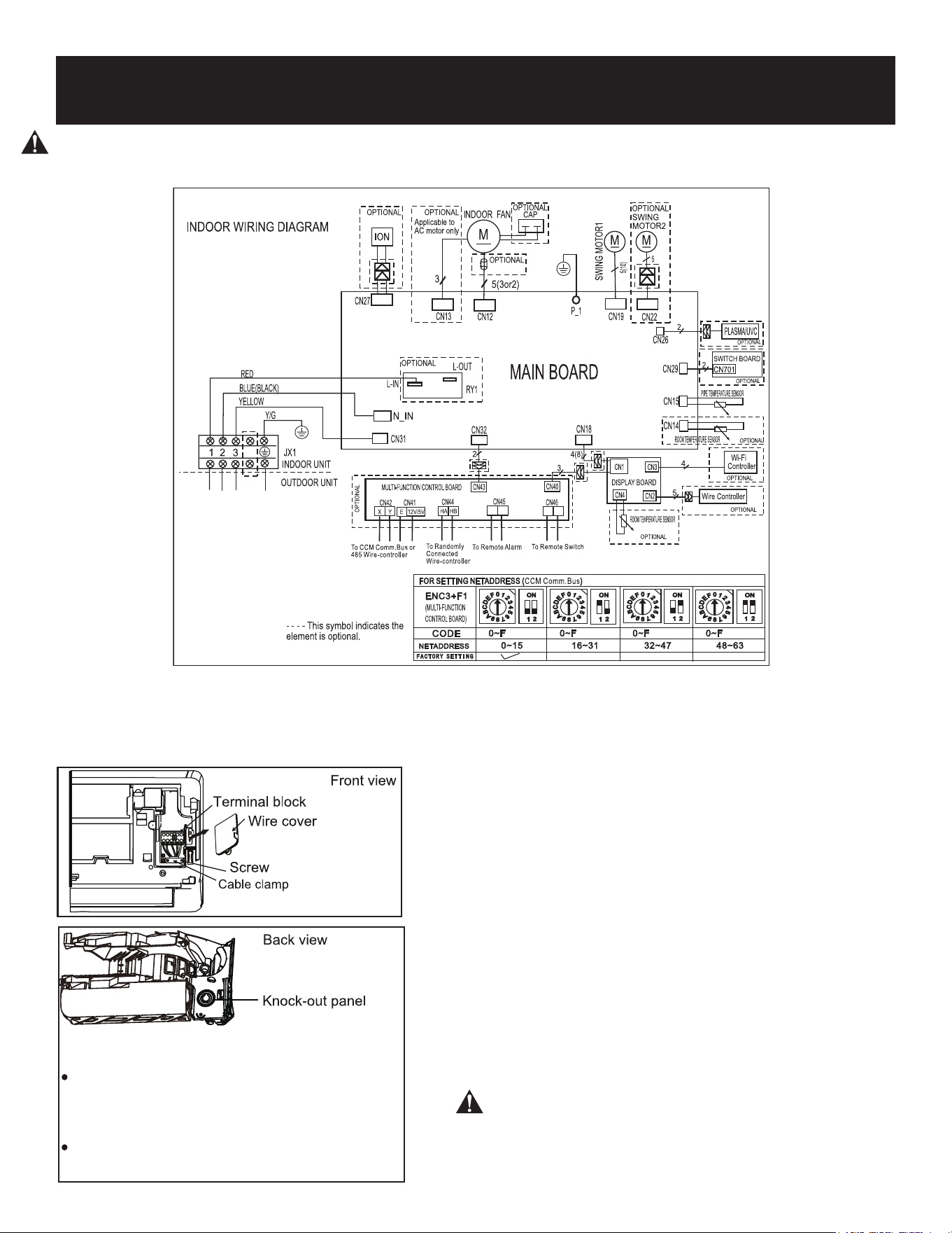
Page 65
CONFIGURACIÓN Y USO
1. Abra el panel frontal de la unidad interior.
2. Usando un destornillador abra la tapa de la
caja de cables en el lado derecho de la unidad
Esto revelará el bloque de terminales.
ADVERTENCIA
Antes de realizar cualquier trabajo eléctrico o de cableado, desconecte la corriente principal
del sistema.
PRECAUCIÓN
NO MEZCLE CABLES VIVOS Y NULOS
Esto es peligroso y puede hacer que la unidad de
aire acondicionado no funcione correctamente.
Para las unidades con cable de cinco núcleos, retire
el pequeño panel desmontable de plástico del
centro para crear una ranura por la que pueda salir
el cable.
Utilice unos alicates de punta de aguja si el panel de
plástico es demasiado difícil de retirar con la mano.
3. Desatornille el campo de cables debajo del
bloque de terminales y colóquelo a un lado.
4. Mirando hacia la parte posterior de la unidad,
retire el panel de plástico de la parte inferior
izquierda.
5. Pase el cable de señal a través de esta ranura,
desde la parte trasera de la unidad hacia la
parte delantera.
6. Mirando hacia la parte frontal de la unidad,
conecte el cable de acuerdo con el diagrama
de cableado de la unidad interior conecte el
conector en U y atornille firmemente cada
cable a su terminal correspondiente.
7. Después de comprobar que todas las
conexiones son seguras, utilice el sujetacables
para fijar el cable de señal a la unidad.
Atornille firmemente la abrazadera del cable.
8. Vuelva a colocar la cubierta del cable en la
parte delantera de la unidad y el panel de
plástico en la parte trasera.
NOTA:
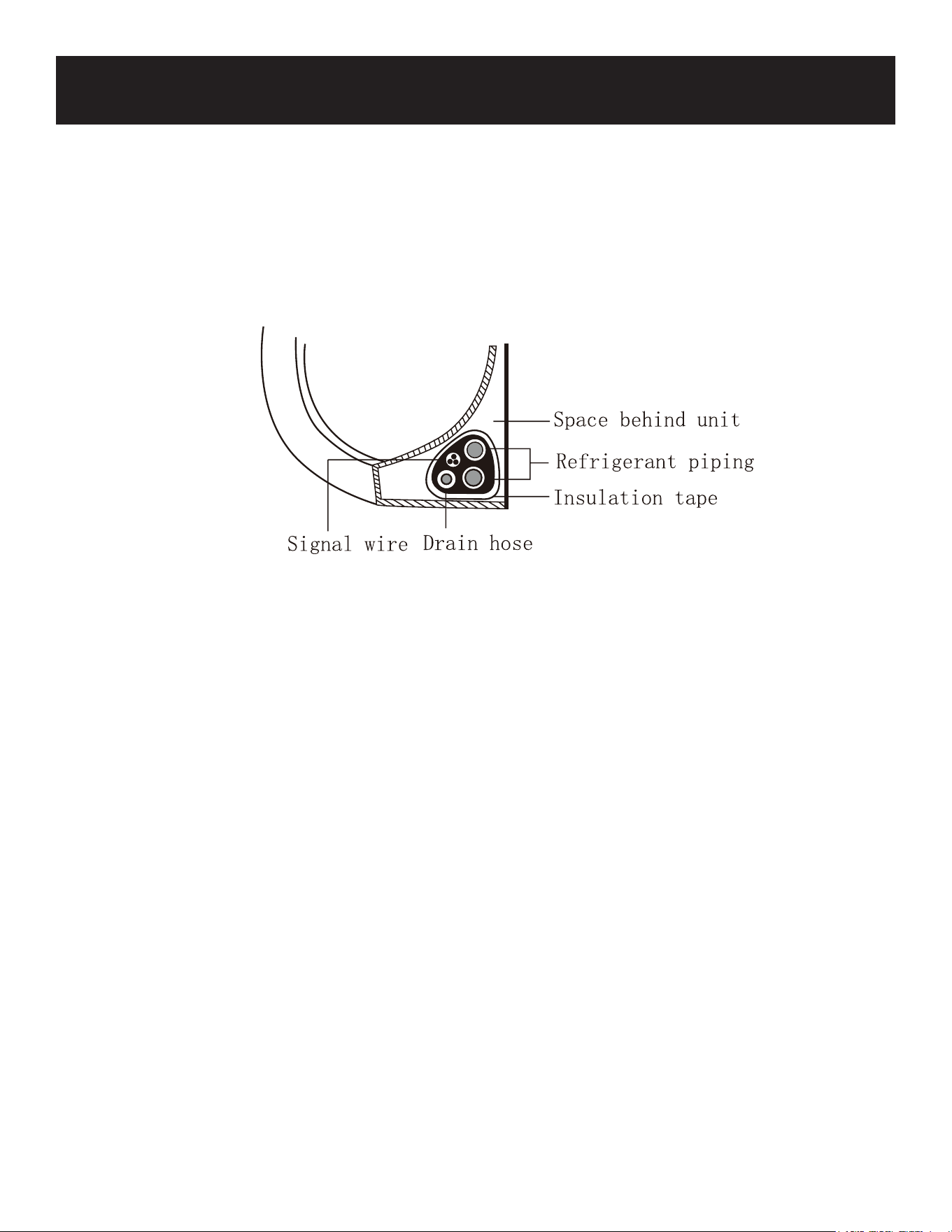
Page 66
NOTA SOBRE EL CABLEADO
EL PROCESO DE CONEXIÓN DEL CABLEADO PUEDE DIFERIR LIGERAMENTE ENTRE
UNIDADES Y REGIONES
1. Agrupe la manguera de drenaje, las tuberías de refrigerante y el cable de señal como se
muestra a continuación.
LA MANGUERA DE DRENAJE DEBE ESTAR EN LA PARTE INFERIOR
Asegúrese de que la manguera de drenaje está en la parte inferior del haz. Colocar la manguera
de drenaje en la parte superior del haz puede provocar el desbordamiento de la bandeja de
drenaje, lo que puede provocar un incendio o daños por agua.
NO ENTRELACE EL CABLE DE SEÑAL CON OTROS CABLES
Mientras agrupa estos elementos, no entrelace ni cruce el cable de señal con ningún otro
cableado.
2. Usando cinta adhesiva de vinilo, fije la manguera de drenaje a la parte inferior de las tuberías
de refrigerante
3. Con cinta aislante, enrolle firmemente el cable de señal, los tubos de refrigerante y la
manguera de drenaje. Compruebe dos veces que todos los elementos están atados. .
NO ENVUELVA LOS EXTREMOS DE LAS TUBERÍAS
Cuando envuelva el paquete, no envuelva los extremos de las tuberías. Necesitará acceder a
ellos para comprobar si hay fugas al final del proceso de instalación (consulte la sección
Comprobación de fugas eléctricas y de gas, página 30 de este manual).
CONFIGURACIÓN Y USO
Unidad interior
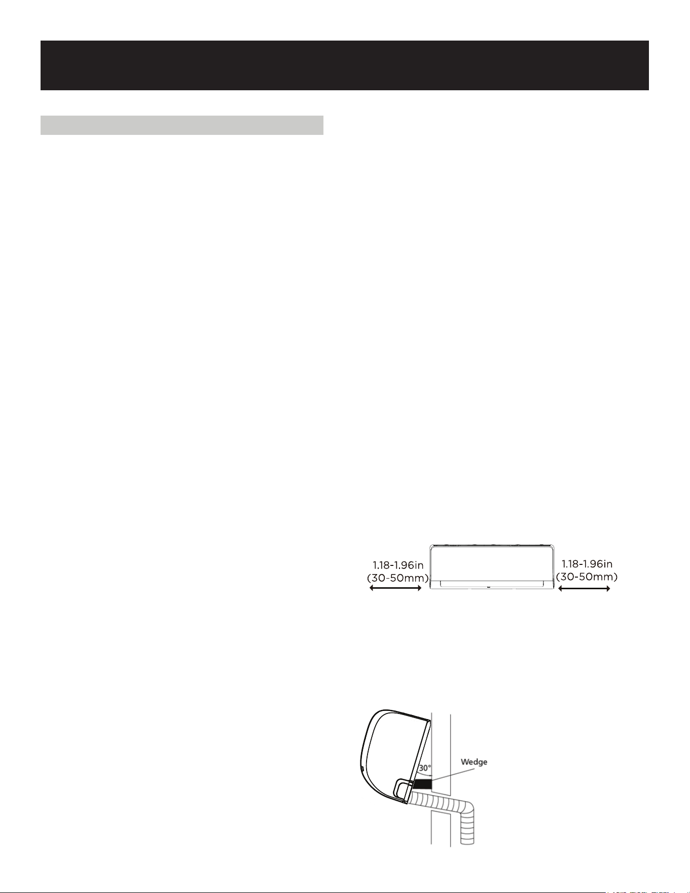
Page 67
CONFIGURACIÓN Y USO
PASO 7: MONTE LA UNIDAD INTERIOR
Si ha instalado nuevas tuberías de conexión a
la unidad exterior, haga lo siguiente:
1. Si ya ha pasado la tubería de refrigerante
a través del orificio de la pared, omita los
puntos 2 y 3, y continúe con el punto 4 a
continuación.
2. De lo contrario, vuelva a comprobar que
los extremos de las tuberías de
refrigerante están sellados para evitar que
entre suciedad o materiales extraños en las
tuberías.
3. Pase lentamente el conjunto envuelto de
tuberías de refrigerante, la manguera de
drenaje y el cable de señal a través del
orificio en la pared.
4. Enganche la parte superior de la unidad
interior en el gancho superior de la placa
de montaje.
5. Compruebe que la unidad está
enganchada firmemente en el montaje
aplicando una ligera presión en los lados
izquierdo y derecho de la unidad. La
unidad no debe sacudirse ni desplazarse.
6. Empuje hacia abajo la mitad inferior de la
unidad ejerciendo una presión uniforme.
Siga empujando hacia abajo hasta que la
unidad encaje en los ganchos a lo largo de
la parte inferior de la placa de montaje.
7. Compruebe de nuevo que la unidad está
firmemente montada aplicando una ligera
presión en los lados izquierdo y derecho
de la unidad.
Si la tubería de refrigerante ya está
empotrada en la pared, haga lo siguiente:
1. Enganche la parte superior de la unidad
interior en el gancho superior de la placa
de montaje.
2. Utilice un soporte o una cuña para
apuntalar la unidad y disponer de
espacio suficiente para conectar la
tubería de refrigerante, el cable de señal y
la manguera de drenaje. (Véase la
ilustración de la derecha).
3. Conecte la manguera de drenaje y la
tubería de refrigerante (consulte la sección
Conexión de la tubería de refrigerante en
la página 25 de este manual para obtener
instrucciones).
4. Mantenga expuesto el punto de conexión
de la tubería para realizar la prueba de
fugas (consulte la sección
Comprobaciones de fugas eléctricas y de
gas, Página 28 de este manual)
5. Después de la prueba de fugas, envuelva
el punto de conexión con cinta aislante.
6. Retire el soporte o cuña que está
apuntalando la unidad.
7. Empuje hacia abajo la mitad inferior de la
unidad ejerciendo una presión uniforme.
Siga empujando hacia abajo hasta que la
unidad encaje en los ganchos de la parte
inferior de la placa de montaje.
LA UNIDAD ES AJUSTABLE
Tenga en cuenta que los ganchos de la placa de
montaje son más pequeños que los orificios de
la parte posterior de la unidad. Si encuentra que
no tiene suficiente espacio para conectar
tuberías empotradas a la unidad interior, la
unidad puede ajustarse a la izquierda o a la
derecha en aproximadamente1.18”-1.96”(30-50
mm), dependiendo del modelo.
Mover hacia la izquierda o
hacia la derecha

Page 68
CONFIGURACIÓN Y USO
INSTALACIÓN DE LA UNIDAD EXTERIOR
Instale la unidad siguiendo los códigos y
regulaciones locales, puede haber ligeras
diferencias entre las distintas regiones.
Instrucciones de instalación - Unidad exterior
Paso 1: Seleccione el lugar de instalación
Antes de instalar la unidad exterior, debe elegir
una ubicación adecuada. Las siguientes normas
le ayudarán a elegir una ubicación adecuada
para la unidad.
Los lugares de instalación adecuados cumplen
las siguientes normas:
Cumple todos los requisitos de espacio indicados
en Requisitos de espacio de instalación más
arriba.
Buena circulación de aire y ventilación.
Firme y sólida: la ubicación puede soportar la
unidad y no vibrará.
El ruido de la unidad no molestará a los demás.
Protegido de periodos prolongados de luz solar
directa o lluvia.
Cuando se prevean nevadas, tome las medidas
adecuadas para evitar la formación de hielo y
daños en la bobina.
NO instale la unidad en los siguientes lugares:
Cerca de un obstáculo que bloquee las
entradas y salidas de aire.
Cerca de una vía pública, zonas concurridas o
donde el ruido de la unidad pueda molestar a
otras personas.
Cerca de animales o plantas que puedan
resultar dañados por la descarga de aire
caliente.
Cerca de cualquier fuente de gas
combustible.
En un lugar expuesto a grandes cantidades
de polvo.
En un lugar expuesto a una cantidad excesiva
de aire salado.
CONSIDERACIONES ESPECIALES PARA
CONDICIONES METEOROLÓGICAS
EXTREMAS
Si la unidad está expuesta a fuertes vientos:
Instale la unidad de manera que el ventilador de
salida de aire esté en un ángulo de 90° con
respecto a la dirección del viento. Si es
necesario, construya una barrera delante de la
unidad para protegerla de vientos
extremadamente fuertes.
Si la unidad está expuesta con frecuencia a
fuertes lluvias o nieve:
Construya un refugio encima de la unidad para
protegerla de la lluvia o la nieve. Tenga cuidado
de no obstruir el flujo de aire alrededor de la
unidad.
Si la unidad está expuesta frecuentemente a
aire salado (costa):
Utilice una unidad exterior especialmente
diseñada para resistir la corrosión.
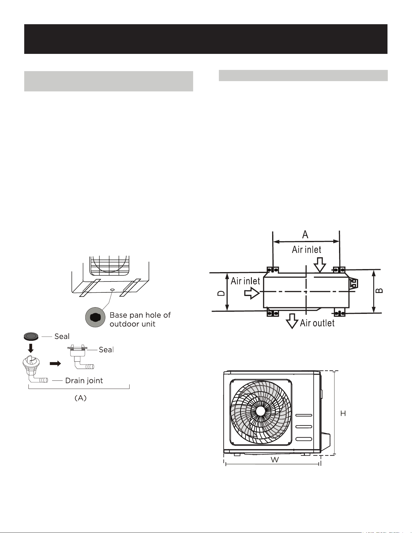
Page 69
CONFIGURACIÓN Y USO
Paso 2: Instale la junta de drenaje (sólo
unidad con bomba de calor)
Antes de atornillar la unidad exterior, debe
instalar la junta de drenaje en la parte inferior
de la unidad. (ver Fig. A)
1. Coloque la junta de goma en el extremo
de la junta de drenaje que se conectará a
la unidad exterior.
2. Inserte la junta de drenaje en el orificio de
la bandeja base de la unidad.
3. Gire la junta de drenaje 90° hasta que
encaje en su sitio mirando hacia la parte
delantera de la unidad
4. Conecte una extensión de manguera de
drenaje (no incluida) a la junta de drenaje
para redirigir el agua de la unidad durante
el modo de calefacción.
EN CLIMAS FRÍOS
En climas fríos, asegúrese de que la manguera
de drenaje esté lo más vertical posible para
garantizar un drenaje rápido del agua. Si el
agua drena demasiado despacio, puede
congelarse en la manguera e inundar la
unidad.
Paso 3: Anclar la unidad exterior
La unidad exterior puede anclarse al suelo o
a un soporte de pared con tornillos M10 (no
incluidos). Prepare la base de instalación de la
unidad de acuerdo con las dimensiones que
se indican a continuación.
DIMENSIONES DE MONTAJE DE LA
UNIDAD
Prepare la base de instalación de la unidad
de acuerdo con las dimensiones indicadas a
continuación.
21.85”
30.12”

Page 70
CONFIGURACIÓN Y USO
Paso 4: Conecte los cables de señal y
corriente
El bloque de terminales de la unidad exterior
está protegido por una cubierta de cableado
eléctrico en el lateral de la unidad. En el interior
de la cubierta de cableado se encuentra
impreso un diagrama de cableado completo.
ADVERTENCIA
ANTES DE REALIZAR CUALQUIER
TRABAJO ELÉCTRICO O DE CABLEADO,
DESCONECTE LA CORRIENTE PRINCIPAL DEL
SISTEMA.
1. Prepare el cable para la conexión:
UTILICE EL CABLE ADECUADO
Elija el cable adecuado, consulte Tipos de
cables en la página 18.
ELIJA EL TAMAÑO DE CABLE ADECUADO
Elija el tamaño de cable adecuado en función
de la corriente admisible mínima indicada en la
placa de características de la unidad.
a. Con un pelacables, pele la cubierta de goma
de ambos extremos del cable para dejar a la
vista aproximadamente 40 mm (1,57”) de los
hilos del interior.
b. Pele el aislamiento de los extremos de los
cables. Usando una crimpadora de alambres,
engarce los conectores en U en los extremos
de los alambres.
c. Utilizando una crimpadora de cables, engarce
los conectores en U en los extremos de los
cables.
PRESTE ATENCIÓN AL CABLE CON
CORRIENTE
Al prensar los cables, asegúrese de distinguir
claramente el cable con corriente (“L”) de los
demás cables.
ADVERTENCIA
TODOS LOS TRABAJOS DE CABLEADO
DEBEN REALIZARSE ESTRICTAMENTE DE
ACUERDO CON EL DIAGRAMA DE CABLEADO
SITUADO EN EL INTERIOR DE LA CUBIERTA
DEL CABLEADO DE LA UNIDAD EXTERIOR.
En Norteamérica
1. Retire la cubierta del cableado de la unidad
aflojando los 3 tornillos.
2. Desmonte las tapas del panel de conductos.
3. Monte temporalmente los tubos de
conducción (no incluidos) en el panel de
conducción.
4. Conecte correctamente las líneas de
corriente y de baja tensión a los terminales
correspondientes del bloque de terminales.
5. Conecte a tierra la unidad de acuerdo con
los códigos locales.
6. Asegúrese de dimensionar cada cable
permitiendo varios centímetros más que la
longitud requerida para el cableado.
7. Utilice contratuercas para asegurar los tubos
de conducción.
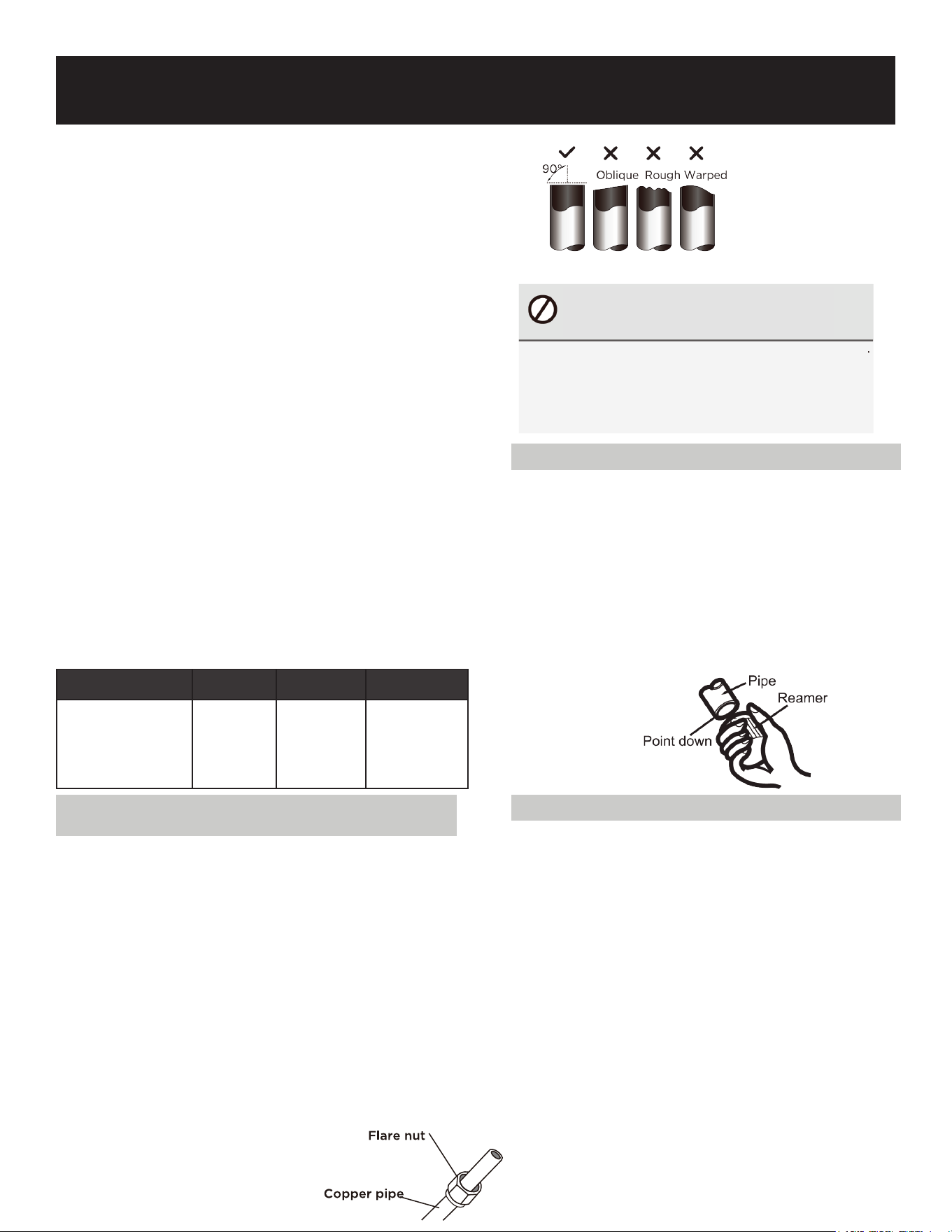
Page 71
CONFIGURACIÓN Y USO
Instrucciones de conexión - Tuberías de
refrigerante
Paso 1: Corte las tuberías
Cuando prepare las tuberías de refrigerante,
tenga especial cuidado en cortarlas y
abocardarlas correctamente. Esto asegurará un
funcionamiento eficiente y minimizará la
necesidad de mantenimiento futuro.
1. Mida la distancia entre las unidades interior y
exterior.
2. Con un cortatubos, corte la tubería un
poco más larga que la distancia medida.
Asegúrese de que la tubería se corta en un
ángulo perfecto de 90°.
3. Asegúrese de que el tubo se corta en un
ángulo perfecto de 90°.
Paso 2: Elimine las rebabas
Las rebabas pueden afectar al sellado
hermético de la conexión de la tubería de
refrigerante. Deben eliminarse por completo.
1. Sujete la tubería en ángulo descendente
para evitar que las rebabas caigan dentro de
la tubería.
2. Utilizando un escariador o una herramienta
de desbarbado, elimine todas las rebabas de
la sección cortada de la tubería.
Paso 3: Abocardar los extremos del tubo
Un abocardado correcto es esencial para
conseguir un sellado hermético.
1. Después de eliminar las rebabas de la
tubería cortada, selle los extremos con
cinta de PVC para evitar que entren
materiales extraños en la tubería.
2. Enfundar la tubería con material aislante.
3. Coloque las tuercas abocardadas en
ambos extremos de la tubería. Asegúrese
de que están orientadas en la dirección
correcta, ya que no podrá colocarlas ni
cambiar su dirección después del
abocardado.
4. Retire la cinta de PVC de los extremos de
CONEXIÓN DE LA TUBERÍA
DE REFRIGERANTE
Cuando conecte las tuberías de refrigerante, no
permita que entren en la unidad sustancias o
gases distintos del refrigerante especificado. La
presencia de otros gases o sustancias reducirá
la capacidad de la unidad y puede causar una
presión anormalmente alta en el ciclo de
refrigeración. Esto puede causar explosiones y
lesiones.
Nota sobre la longitud de las tuberías
La longitud de las tuberías de refrigerante
afectará al rendimiento y a la eficiencia
energética de la unidad. La eficiencia nominal se
prueba en unidades con una longitud de tubería
de 16,5 pies (5 metros) En Norteamérica, la
longitud de tubería estándar es de 25 (75
metros). Se requiere una longitud mínima de
tubería de 3 metros para minimizar las
vibraciones y el ruido excesivo.
Longitud máxima y altura de caída de la
tubería de refrigerante por modelo de unidad
Modelo
Capacidad
(BTU/h)
Máx. Longi-
tud
Max. Caída
Aire acondicionado
split Inverter R410A,
R32
<15,000
82 pies (25
metros)
33 pies (10
metros)
NO DEFORME EL TUBO
DURANTE EL CORTE
Tenga mucho cuidado de no dañar,
abollar o deformar el tubo durante
el corte. Esto reducirá drásticamente
la eficacia calorífica de la unidad.
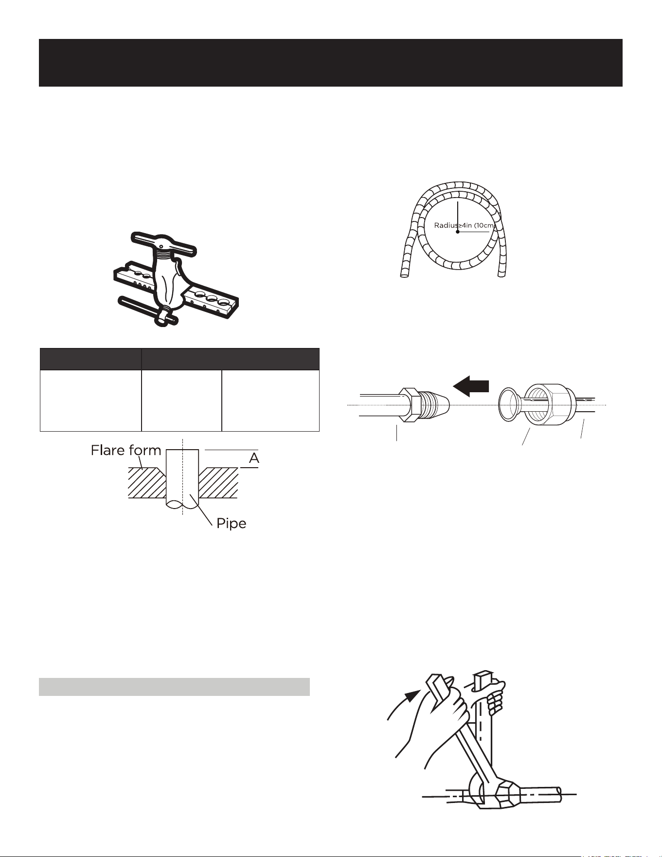
Page 72
CONFIGURACIÓN Y USO
la tubería cuando esté listo para
realizar el trabajo de abocardado.
5. Sujete el abocardador al extremo de la
tubería. El extremo de la tubería debe
sobresalir del borde del abocardador de
acuerdo con las dimensiones indicadas en
la tabla siguiente.
6. Coloque la herramienta de abocardado en
la forma.
PIPING EXTENSION BEYOND FLARE FORM
Outer Diameter of
Pipe
A
Min. Max.
Ø .25” (6.35 mm) .275” (.7 mm) .5” (1.3 mm)
7. Gire el mango de la herramienta de
abocardado en el sentido de las agujas del
reloj hasta que el tubo esté completamente
abocardado.
8. Retire la herramienta de abocardado y el
molde de abocardado y, a continuación,
inspeccione el extremo de la tubería para
comprobar que no presenta grietas y que el
abocardado es uniforme.
Paso 4: Conectar las tuberías
Al conectar las tuberías de refrigerante,
tenga cuidado de no aplicar un torque
excesivo ni deformar las tuberías de ninguna
manera. Conecte primero la tubería de baja
presión y después la de alta presión.
RADIO MÍNIMO DE CURVATURA
Al doblar las tuberías de refrigerante de
conexión, el radio de curvatura mínimo es de
4” (10 cm).
Instrucciones para conectar las tuberías a la uni-
dad interior
1. Alinee el centro de las dos tuberías que va a
conectar.
2. Apriete la tuerca abocardada con la mano lo
más fuerte posible.
3. Con una llave, sujete la tuerca en la tubería
de la unidad.
4. Mientras sujeta firmemente la tuerca en la
tubería de la unidad, utilice una llave
dinamométrica para apretar la tuerca de
abocardado de acuerdo con los valores de
torque de la tabla Requisitos de torque de la
página 25. Afloje el antiestético abocardado
y vuelva a apretarlo.
Tubería de la
unidad interior
Tuerca
abocardada
Tubería
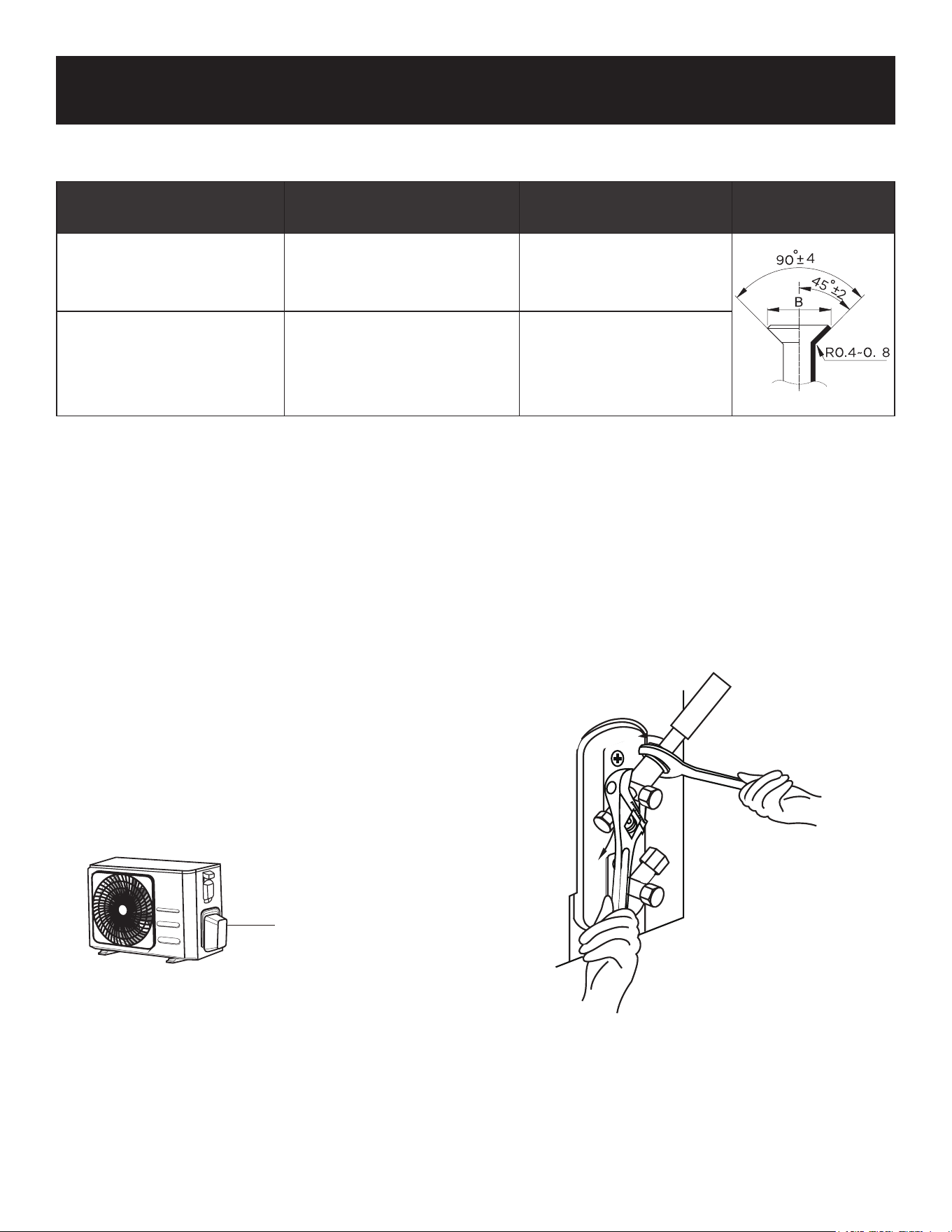
Page 73
CONFIGURACIÓN Y USO
REQUISITOS DE PAR
NO UTILICE UN PAR DE APRIETE EXCESIVO
Una fuerza excesiva puede romper la tuerca o dañar las tuberías de refrigerante. No debe
exceder los requisitos de par de apriete indicados en la tabla anterior.
1. Desenrosque la tapa de la válvula
empaquetada en el lateral de la unidad
exterior.
2. Retire las tapas protectoras de los
extremos de las válvulas.
3. Alinee el extremo abocinado de la
tubería con cada válvula y apriete la
tuerca abocinada con la mano lo más
fuerte posible.
4. Con una llave, sujete el cuerpo de la
válvula. No agarre la tuerca que sella la
válvula de servicio.
INSTRUCCIONES PARA CONECTAR LAS TUBERÍAS A LA UNIDAD EXTERIOR
Diámetro exterior del
tubo
Par de apriete
(N*m)
Dimensión del
abocardado (B)
Forma de
abocardado
Ø 0.25” (Ø 6.35 mm) 18~20 (180~200kgf.cm)
0.33” -.34” (8.4-8.7
mm)
Ø 0.5” (Ø 12.7 mm) 49~59 (490~590kgf.cm)
0.64” -.65” (16.2 - 16.5
mm)
Valve cover
5. Mientras sujeta firmemente el cuerpo
de la válvula, utilice una llave
dinamométrica para apretar la tuerca
abocardada de acuerdo con los
valores de par correctos.
6. Afloje ligeramente la tuerca de
abocardado y vuelva a apretarla.
7. Repita los pasos 3 a 6 para el resto de
la tubería.
UTILICE LA LLAVE PARA APRETAR EL
CUERPO PRINCIPAL DE LA VÁLVULA
El par de apriete de la tuerca de
abocardado puede romper otras partes
de la válvula.
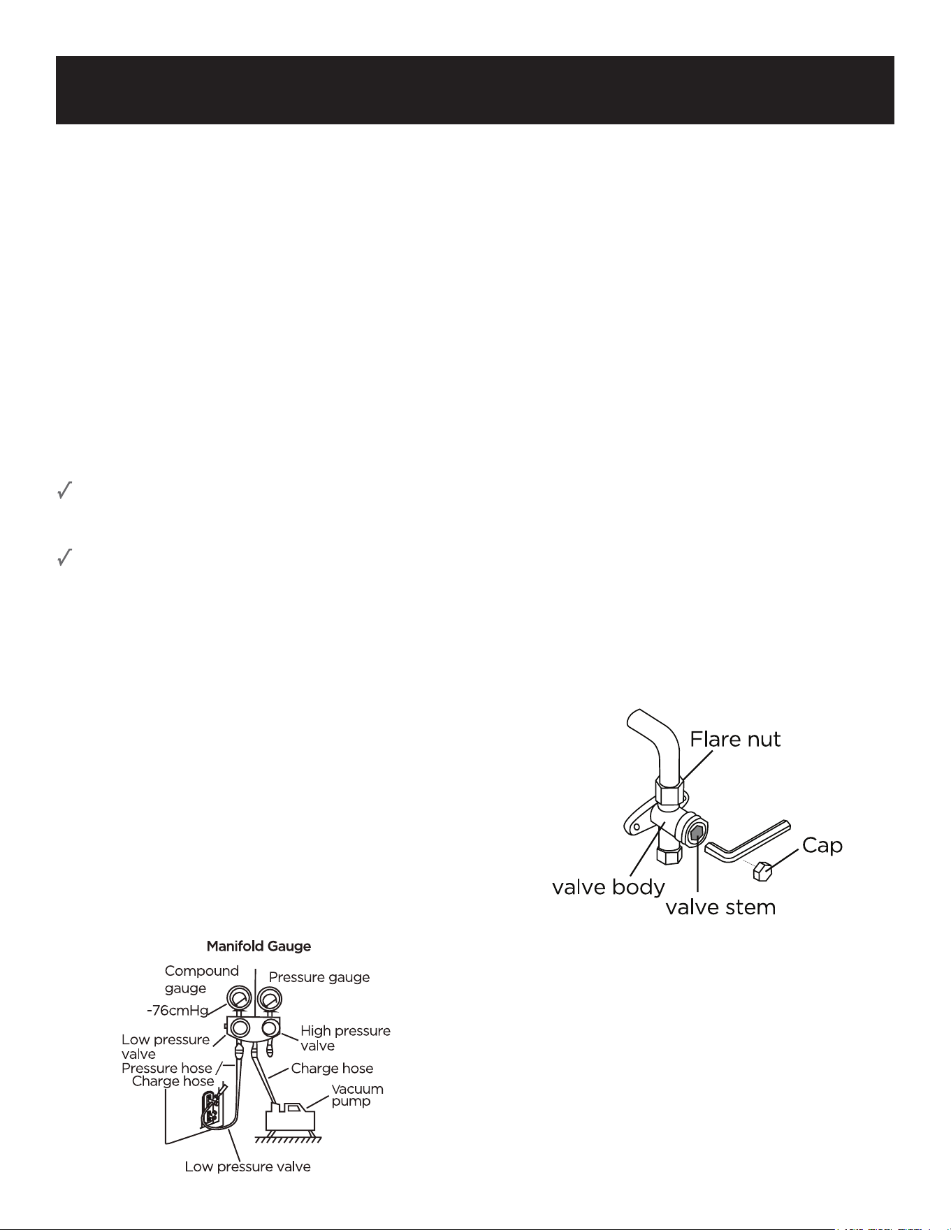
Page 74
CONFIGURACIÓN Y USO
EVACUACIÓN DEL AIRE
Preparativos y precauciones
El aire y las materias extrañas en el circuito
del refrigerante pueden causar aumentos
anormales de la presión, lo que puede dañar
el aire acondicionado, reducir su eficiencia y
causar lesiones. Utilice una bomba de vacío
y un manómetro para evacuar el circuito de
refrigerante, eliminando cualquier gas no
condensable y la humedad del sistema.
La evacuación debe realizarse en el
momento de la instalación inicial y cuando se
traslade la unidad.
ANTES DE REALIZAR LA EVACUACIÓN
Compruebe que las tuberías de conexión
entre las unidades interior y exterior están
conectadas correctamente.
Compruebe que todo el cableado está
conectado correctamente.
Instrucciones de evacuación
1. Conecte la manguera de carga del
manómetro al puerto de servicio de la
válvula de baja presión de la unidad
exterior.
2. Conecte otra manguera de carga del
manómetro a la bomba de vacío.
3. Abra el lado de baja presión del
manómetro. Mantenga cerrado el lado de
Alta presión.
4. Encienda la bomba de vacío para evacuar el
sistema.
5. Haga funcionar el vacío durante al menos 15
minutos, o hasta que el medidor de
compuesto indique-76cmHG (-105Pa).
6. Cierre el lado de baja presión del
manómetro y apague la bomba de vacío.
7. Espere 5 minutos y, a continuación,
compruebe que no se ha producido ningún
cambio en la presión del sistema.
8. Si hay un cambio en la presión del sistema,
consulte la sección Comprobación de fugas
de gas para obtener información sobre
cómo comprobar si hay fugas. Si no hay
cambios en la presión del sistema,
desenrosque el tapón de la válvula
empaquetada (válvula de alta presión).
9. Inserte la llave hexagonal en la válvula
empaquetada (válvula de alta presión) y
abra la válvula girando la llave 1/4 de vuelta
en sentido contrario a las agujas del reloj.
Escuche si el gas sale del sistema, luego
cierre la válvula después de 5 segundos.
10. Observe el manómetro durante un minuto
para asegurarse de que no hay cambios en
la presión. El manómetro debe indicar una
presión ligeramente superior a la
atmosférica.
11. Retire la manguera de carga del puerto de
servicio.
12. Con una llave hexagonal, abra
completamente las válvulas de alta y baja
presión.
13. Apriete a mano los tapones de las tres
válvulas (puerto de servicio, alta presión y
baja presión). Si es necesario, puede
apretarlos aún más con una llave
dinamométrica.
ABRA SUAVEMENTE LAS VÁLVULAS
Al abrir los vástagos de las válvulas, gire la llave
hexagonal hasta que choque contra el tapón.
No intente forzar la válvula para que se abra
más.
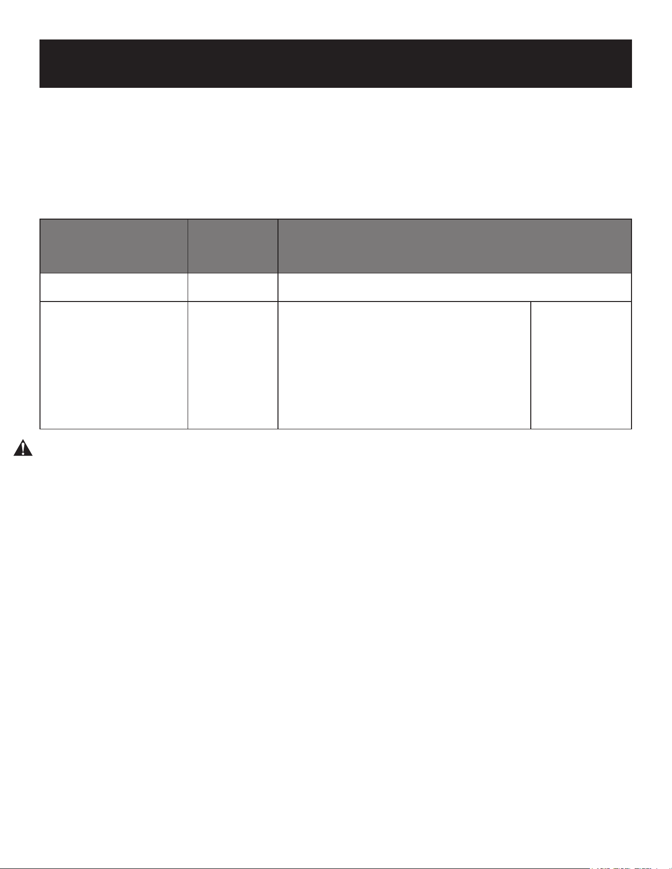
Page 75
CONFIGURACIÓN Y USO
Nota sobre la adición de refrigerante
Algunos sistemas requieren una carga adicional en función de la longitud de las tuberías. En
Norteamérica, la longitud estándar de las tuberías es de 7,5 metros. El refrigerante debe
cargarse desde el puerto de servicio de la válvula de baja presión de la unidad exterior. El
refrigerante adicional que debe cargarse puede calcularse mediante la siguiente fórmula.
REFRIGERANTE ADICIONAL POR LONGITUD DE TUBERÍA
Longitud de la tubería
de conexión (m)
Método de
purga de aire
Refrigerante adicional
< Longitud de tubo
estándar
Bomba de
vacío
N/A
> Longitud de tubo
estándar
Bomba de
vacío
Liquid Side: Ø 0.25” (Ø 6.35 mm)
R410A:
(Pipe length – standard length) x 0.16 Oz./ft
(Pipe length – standard length) x 30g/meters
Liquid Side:
Ø 0.375”
(Ø 9.52 mm)
PRECAUCIÓN: NO mezcle los tipos de refrigerante.
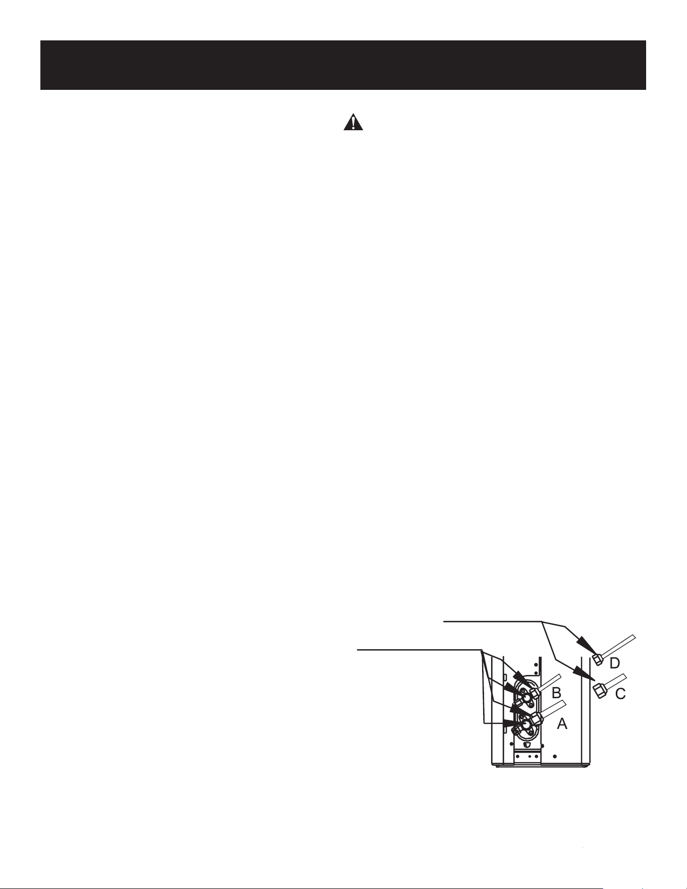
Page 76
CONFIGURACIÓN Y USO
COMPROBACIONES DE FUGAS ELÉCTRICAS Y
DE GAS
Antes de la prueba de funcionamiento
Realice la prueba de funcionamiento sólo
después de haber completado los siguientes
pasos:
• Comprobaciones de seguridad eléctrica
- Confirme que el sistema eléctrico de la
unidad es seguro y funciona correctamente.
• Comprobaciones de fugas de gas
- Compruebe todas las conexiones de las
tuercas abocardadas y confirme que el
sistema no tiene fugas.
• Confirme que las válvulas de gas y líquido
(alta y baja presión) están completamente
abiertas.
Comprobaciones de seguridad eléctrica
Después de la instalación, confirme que todo el
cableado eléctrico esté instalado de
acuerdo con las normativas locales y
nacionales, y según el Manual de instalación.
ANTES DE LA PRUEBA DE FUNCIONAMIENTO
Compruebe la conexión a tierra
Mida la resistencia de puesta a tierra mediante
detección visual y con un comprobador de
resistencia de puesta a tierra. La resistencia de
puesta a tierra debe ser inferior a 0,1 Ω.
NOTA: Esto puede no ser necesario para
algunas ubicaciones en Norteamérica.
DURANTE LA PRUEBA
Comprobación de fugas eléctricas
Durante la Prueba de Funcionamiento, utilice
una electro sonda y un multímetro para realizar
una prueba exhaustiva de fugas eléctricas.
Si se detecta una fuga eléctrica, apague la
unidad inmediatamente y llame a un electricista
autorizado para que encuentre y resuelva la
causa de la fuga.
NOTA: Esto puede no ser necesario en algunos
lugares de Norteamérica.
ADVERTENCIA - RIESGO DE DESCARGA
ELÉCTRICA
TODO EL CABLEADO DEBE CUMPLIR CON
LOS CÓDIGOS ELÉCTRICOS LOCALES Y
NACIONALES, Y DEBE SER INSTALADO
POR UN ELECTRICISTA AUTORIZADO.
Comprobación de fugas de gas
Existen dos métodos diferentes para
comprobar si hay fugas de gas.
Método de agua y jabón
Con un cepillo suave, aplique agua
jabonosa o detergente líquido a todos
los puntos de conexión de las tuberías de
la unidad interior y la unidad exterior. La
presencia de burbujas indica una fuga.
Método del detector de fugas
Si utiliza un detector de fugas, consulte el
manual de funcionamiento del dispositivo
para obtener instrucciones de uso
adecuadas.
DESPUÉS DE REALIZAR LA
COMPROBACIÓN DE FUGAS DE GAS
Después de confirmar que NO hay fugas
en todos los puntos de conexión de las
tuberías, vuelva a colocar la tapa de la
válvula en la unidad exterior.
A: Válvula de cierre de baja presión
B: Válvula de cierre de alta presión
C y D: Tuercas abocardadas de la unidad interior
Punto de control de la unidad interior
Punto de control de la unidad exterior
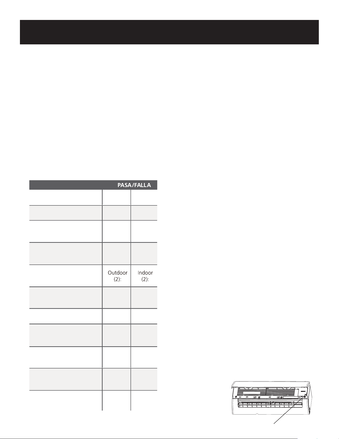
Page 77
CONFIGURACIÓN Y USO
PRUEBA DE FUNCIONAMIENTO
Instrucciones para la prueba de funcionamiento
Debe realizar la prueba de funcionamiento
durante al menos 30 minutos.
1. Conecte la corriente a la unidad.
2. Pulse el botón ON/OFF del control remoto
para encenderlo.
3. Pulse el botón MODE (MODO) para
desplazarse por las siguientes funciones, de
una en una:
• COOL (FRIO) - Seleccione la temperatura
más baja posible.
• HEAT (CALOR) - Seleccione la temperatura
más alta posible.
COMPRUEBE DOS VECES LAS CONEXIONES
DE LAS TUBERÍAS
Durante el funcionamiento, la presión del
circuito de refrigerante aumentará. Esto
puede revelar fugas que no estaban
presentes durante la comprobación inicial de
fugas. Durante la prueba de funcionamiento,
compruebe que no haya fugas en ninguno de
los puntos de conexión de las tuberías de
refrigerante. Consulte la sección
Comprobación de fugas de gas para obtener
instrucciones.
SI LA TEMPERATURA AMBIENTE ES INFERIOR
A60°F (16°C)
No utilice el control remoto para activar la
función de Enfriamiento cuando la temperatura
ambiente sea inferior a 60°F (16°C). Utilice el
botón MANUAL CONTROL (CONTROL
MANUAL) para probar la función COOL (FRÍO).
1. Levante el panel frontal de la unidad interior
y levántelo hasta que encaje en su lugar.
2. El botón MANUAL CONTROL (CONTROL
MANUAL) se encuentra en el lado derecho
de la unidad. Púlselo 2 veces para
seleccionar la función COOL (FRÍO).
3. Realice la prueba de funcionamiento
normalmente.
4. Deje que cada función funcione durante 5
minutos y realice las siguientes
comprobaciones.
5. Una vez finalizada con éxito la prueba de
funcionamiento y tras confirmar que todos
los puntos de comprobación de la lista de
comprobaciones a realizar se han
superado, haga lo siguiente:
a. Utilizando el control remoto, vuelva a
poner la unidad a la temperatura normal
de funcionamiento.
b. Envuelva con cinta aislante las
conexiones de las tuberías de refrigerante
interiores que dejó al descubierto durante
el proceso de instalación de la unidad
interior.
Lista de comprobaciones a realizar
No hay fugas eléctricas
La unidad está correctamente
conectada a tierra
Todos los terminales eléctricos
están bien cubiertos
Las unidades interior y exterior
están sólidamente instaladas
Todos los puntos de conexión
de tuberías no presentan fugas
El agua sale correctamente por
la manguera de drenaje
Todas las tuberías están cor-
rectamente aisladas
La unidad funciona correcta-
mente en frío
La unidad realiza correcta-
mente la función CALOR
Las rejillas de la unidad interior
giran correctamente
Las rejillas de la unidad interior
giran correctamente
Botón de control manual
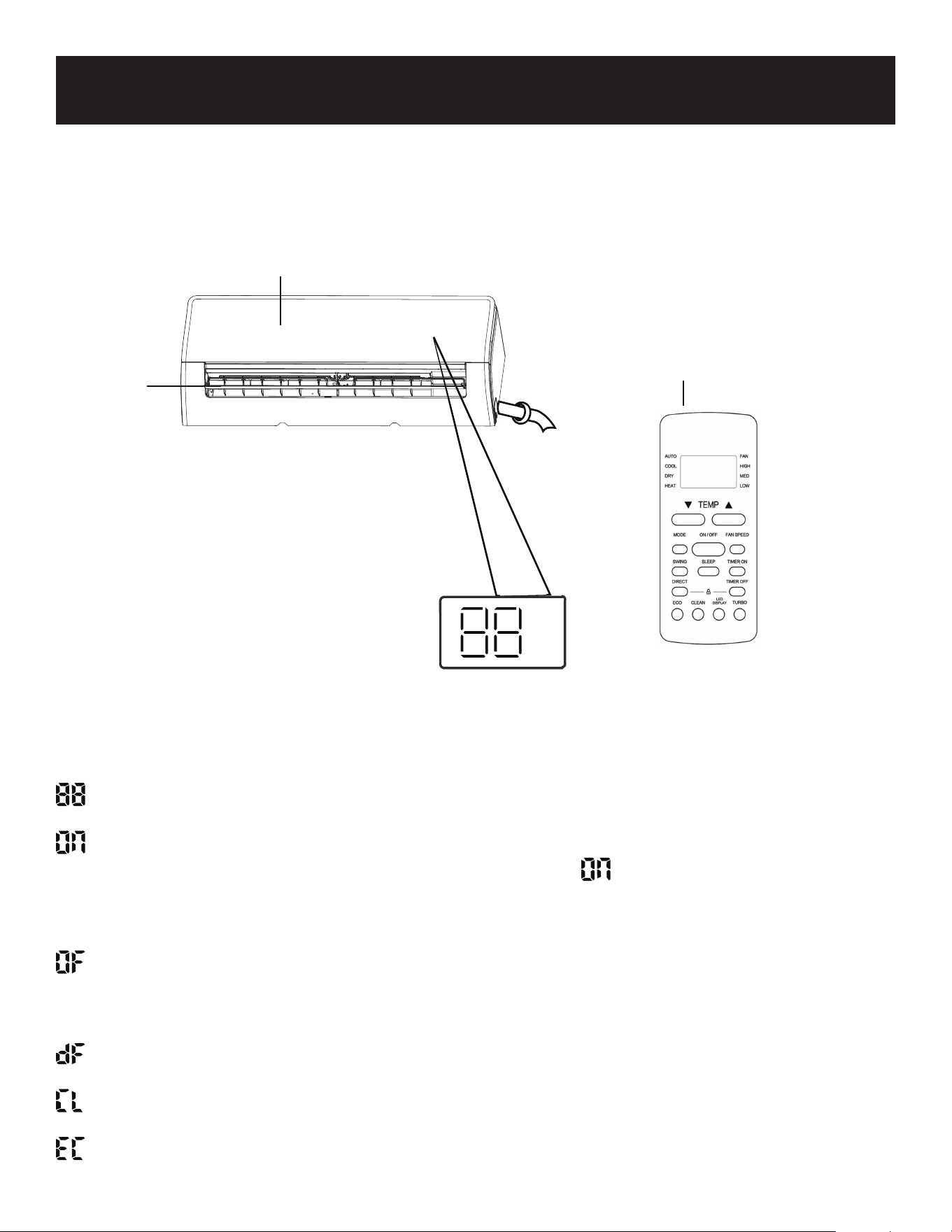
Page 78
CONFIGURACIÓN Y USO
Significado de los códigos de la pantalla
Muestra la temperatura, la característica de funcionamiento y los códigos de error:
durante 3 segundos cuando:
• TIMER ON está ajustado (si la unidad está apagada, permanece encendido
cuando TIMER ON está ajustado)
• SWING, TURBO, la función ECO está activada.
durante 3 segundos cuando:
• TIMER OFF iestá ajustado.
• SWING, TURBO, la función ECO está desactivada.
durante la descongelación.
cuando la función Clean (Limpiar) está activada.
cuando la unidad detecta una fuga de refrigerante.
Pantalla de la unidad interior
Panel frontal
Control remoto
Persiana
Page 79
CONFIGURACIÓN Y USO
MANEJO DE LAS PILAS ALCALINAS
1. NUNCA mezcle pilas alcalinas, estándar (carbono-zinc), recargables (níquel-cadmio) con este
producto.
2. Si el líquido de la pila entrara accidentalmente en contacto con los ojos, existe peligro de
pérdida de visión, no se los frote. Enjuáguese inmediatamente los ojos con agua limpia del grifo
y consulte inmediatamente a un médico.
3. No ponga la batería en el fuego, no la exponga al calor, no la desmonte ni la modifique. Si se
daña el aislamiento o la válvula de seguridad, la batería puede perder líquido, sobrecalentarse o
explotar.
4. No inserte la batería con los polos invertidos. Hacerlo puede provocar alguna anomalía o un
cortocircuito y la batería puede perder líquido, sobrecalentarse o explotar.
5. Mantenga la batería fuera del alcance de los niños. En caso de ingestión de la batería, póngase
en contacto con un médico inmediatamente.
6. Si el líquido alcalino entra en contacto con la boca, enjuáguese la boca con agua y póngase en
contacto con un médico inmediatamente.
7. Si el líquido alcalino entra en contacto con la piel o la ropa, puede quemar la piel, enjuague a
fondo la zona afectada con agua del grifo, Si se produce una quemadura química o si persiste la
irritación, busque atención médica.
8. No mezcle pilas nuevas y usadas o de otras marcas. Los diferentes atributos pueden hacer que
la batería pierda líquido, se sobrecaliente o explote.
9. Esta batería no ha sido fabricada para ser recargada. Recargar esta batería puede dañar el
aislamiento o la estructura interna y puede provocar que la batería pierda líquido, se
sobrecaliente o explote.
10. No dañe ni retire la etiqueta del exterior de la batería. Hacerlo puede provocar un cortocircuito,
fugas de líquido, sobrecalentamiento o explosión de la batería.
11. No deje caer, lance ni exponga la batería a golpes fuertes. De lo contrario, la batería podría
perder líquido, sobrecalentarse o explotar.
12. No modifique la forma de la batería. Si se daña el aislamiento o la válvula de seguridad, la
batería puede perder líquido, sobrecalentarse o explotar.
13. Retire inmediatamente las pilas cuando hayan perdido toda su potencia. Dejar las baterías en la
unidad durante mucho tiempo puede provocar que las baterías pierdan líquido, se
sobrecalienten o exploten debido al gas que generan las baterías.
14. Retire las pilas de la unidad cuando no vaya a utilizarla durante un largo periodo de tiempo. Las
pilas pueden perder líquido, sobrecalentarse o explotar debido al gas que generan las pilas.
15. No aplique soldadura directamente a las pilas. El calor puede hacer que las pilas pierdan líquido,
se sobrecalienten o exploten.
16. No moje las pilas. Si lo hace, las pilas podrían sobrecalentarse.
17. Guarde las pilas en un lugar alejado de la luz solar directa, donde la temperatura y la humedad
no sean elevadas. No hacerlo puede provocar que las pilas pierdan líquido, se sobrecalienten o
exploten. Además, puede causar que la vida y el rendimiento de las baterías disminuyan.
18. Siga las regulaciones del gobierno local cuando se deshaga de estas baterías.
GUARDE ESTAS INSTRUCCIONES
USO EXCLUSIVAMENTE DOMÉSTICO
Al manipular pilas alcalinas, deben seguirse las precauciones básicas de
seguridad, incluyendo las siguientes:
ADVERTENCIA

Page 80
CONFIGURACIÓN Y USO
USO CORRECTO
Apunte el control remoto al receptor del aparato, El control remoto no debe estar a más de
MAX: 26 Pies (8 Metros) de distancia del aparato (sin obstáculos entre el control remoto y el
receptor).
El control remoto debe manejarse con extremo
cuidado. No lo deje caer ni lo exponga a la luz
directa del sol o a fuentes de calor.
INSTALACIÓN DE LAS PILAS (PILAS NO INCLUIDAS)
1. Deslice para abrir la tapa del compartimento de las pilas.
2. Inserte 2 pilas “AAA” como se muestra a continuación.
3. Deslice hacia atrás la tapa del compartimento de las pilas.
Si se sustituye o desecha el control remoto, las pilas
deben extraerse y desecharse de acuerdo con la
legislación vigente, ya que son perjudiciales para el
medio ambiente.
MAX: 26 Feet (8 Meters)
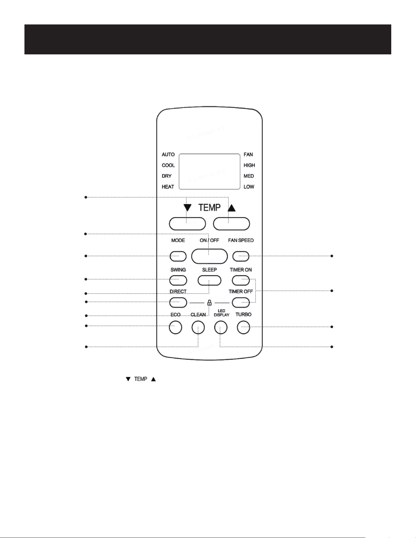
Page 81
CONFIGURACIÓN Y USO
CONTROL REMOTO
1
2
3
5
8
9
10
12
11
13
4
7
6
1. ON/OFF: Pulse para encender o apagar.
2. Aumenta la temperatura en incrementos de 1°F (1°C). La temperatura máxima es de 30°C
(86°F). Disminuye la temperatura en incrementos de 1°F (1°C). La temperatura mínima es de 16°C
(60°F). Estos botones también se utilizan para ajustar la hora
3. MODE (MODO): Pulse para desplazarse por AUTO (AUTOMÁTICA), COOL (FRIO), DRY (SECO),
HEAT (CALOR), FAN (VENTILADOR).
4. FAN SPEED (VELOCIDAD DEL VENTILADOR): Se utiliza para seleccionar la velocidad del ventilador
HIGH (ALTA), MED (MEDIA), LOW (BAJA) o AUTO (AUTOMÁTICA).
5. SWING (OSCILACIÓN): Activa la rejilla para que oscile hacia UP/DOWN (ARRIBA/ABAJO).
6. SLEEP: Aumenta gradualmente la temperatura en modo COOL (FRIO) o la disminuye en modo
HEAT (CALOR).
7. TIMER ON (TEMPORIZADOR ENCENDIDO): Ajuste el TIMER (TEMPORIZADOR) para AUTO START
(ARRANQUE AUTOMÁTICO)
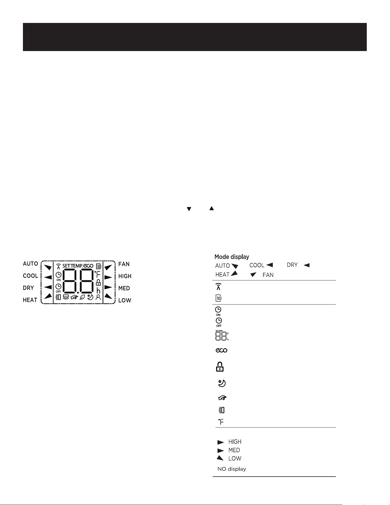
Page 82
CONFIGURACIÓN Y USO
TIMER OFF (TEMPORIZADOR APAGADO): Ajuste el TIMER (TEMPORIZADOR) para AUTO STOP
(DETENCION AUTOMATICA).
8. DIRECT (DIRECTO): Ajuste el ángulo de las rejillas 6 grados cada vez.
9. ECO: Una vez alcanzada la temperatura seleccionada, el compresor se apagará y sólo funcionará el
ventilador para seguir haciendo circular el aire en la habitación.
10. CLEAN: (LIMPIAR): START/STOP (EMPIEZA/DETIENE) la función CLEAN (LIMPIAR).
11. TURBO: La alta velocidad del ventilador hace que la unidad alcance la temperatura de refrigeración
ajustada lo antes posible.
12. LOCK (BLOQUEO): Pulse los botones DIRECT y TIMER OFF al mismo tiempo durante 5 segundos
para bloquear los botones del control remoto. Esto puede evitar cambios
involuntarios en los ajustes del aire acondicionado. Pulse los botones DIRECT y
TIMER OFF al mismo tiempo durante 2 segundos para desbloquear los botones.
13. LED DISPLAY (PANTALLA LED): Pulse para apagar la pantalla LED de la unidad interior.
14. °C / °F SELECTOR (SELECTOR °C/°F): Pulse and al mismo tiempo durante 3 segundos para
cambiar las unidades de temperatura entre Fahrenheit y
Celsius.
La información se muestra cuando se enciende el control remoto.
NOTA: Todos los indicadores mostrados en
la figura son meramente informativos.
Durante el funcionamiento real, sólo se
muestran en la pantalla LED las
funciones relevantes.
Se muestra cuando se transmiten datos
Se muestra cuando el control remoto está
encendido
Se muestra cuando se establece el tiempo de
TIMER ON
Se muestra cuando se establece el tiempo de
TIMER OFF
Muestra la temperatura establecida o la temperatura ambiente,
o el tiempo en la configuración del TEMPORIZADOR
Se muestra cuando la función ECO está activada
Indicó que todas las configuraciones actuales están
bloqueadas.
Se muestra cuando la función SLEEP está activada
Se muestra cuando la función TURBO está activada
Pantalla de oscilación automática de rejilla horizontal
Consejos para cambiar la unidad de temperatura
Indicación de velocidad del ventilador
Alta velocidad
Velocidad media
Baja velocidad
Velocidad automática del ventilador
Page 83
CONFIGURACIÓN Y USO
ON/OFF: Pulse para encender o apagar.
Aumenta la temperatura en incrementos de 1°F (1°C). La temperatura máxima es de 30°C
(86°F).
Disminuye la temperatura en incrementos de 1°F (1°C). La temperatura mínima es de 60°F
(16°C)
Estos botones también se utilizan para ajustar la hora.
MODE (MODO): Pulse para desplazarse por AUTO (AUTOMATICO), COOL (FRIO), DRY
(SECO), HEAT (CALOR), FAN (VENTILADOR).
El símbolo correspondiente se iluminará en la pantalla LED del control remoto
para indicar el modo seleccionado.
AUTO (AUTOMATICO) Seleccione la temperatura deseada 60-86°F (16-30°C) pulsando los
botones hasta que la temperatura deseada aparezca en la
pantalla LED del control remoto. La unidad seleccionará
automáticamente el modo COOL (FRÍO) o HEAT (CALOR) y la
velocidad del ventilador correspondiente en función de la temperatura
ajustada.
COOL (FRIO): Seleccione la temperatura deseada 60-86°F (16-30°C) pulsando los botones
hasta que aparezca la temperatura deseada en la pantalla LED del
control remoto. Pulse el botón Fan Speed (velocidad del ventilador) para
seleccionar velocidad Low (baja), Medium (media), High (alta) o Auto
(automática).
DRY (SECO): Ideal para reducir la humedad. Seleccione la temperatura objetivo 60-86°F
(16-30°C). La velocidad del ventilador no se puede seleccionar en este modo.
Mantenga la ventana y la puerta cerradas para obtener el mejor efecto
deshumidificador.
HEAT (CALOR): Seleccione la temperatura objetivo 60-86°F (16-30°C) pulsando hasta
que aparezca la temperatura deseada en la pantalla LED. Pulse el botón Fan
Speed (velocidad del ventilador) para seleccionar velocidad Low (baja),
Medium (media), High (alta) o Auto (automática).
FAN (VENTILADOR): Pulse el botón Fan Speed (Velocidad del ventilador) para seleccionar
Low (Baja), Medium (Media), High (Alta) o Auto Speed (Automática).
FAN SPEED (VELOCIDAD DEL VENTILADOR): Permite seleccionar la velocidad del ventilador
en HIGH (ALTA), MED (MEDIA), LOW (BAJA) o
AUTO (AUTOMÁTICA).
SWING (OSCILACIÓN): Activa la rejilla para que oscile hacia UP/DOWN (ARRIBA/ABAJO).
Page 84
CONFIGURACIÓN Y USO
SLEEP: Aumente gradualmente la temperatura en modo COOL (FRÍO) o disminúyala en modo
HEAT (CALOR).
La función SLEEP se utiliza para disminuir gradualmente el consumo de energía mientras
usted duerme y no necesita los mismos ajustes de temperatura para mantenerse cómodo.
Esta función sólo se puede activar con el control remoto. La función SLEEP no está
disponible en los modos FAN o DRY
Pulse el botón SLEEP cuando esté listo para irse a dormir.
Cuando esté en modo COOL (FRÍO), la unidad aumentará la temperatura en 2°F (1°C)
después de 1 hora y aumentará otros 2°F (1°C) después de otra hora.
Cuando está en modo HEAT (CALOR), la unidad disminuirá la temperatura en 2°F (1°C)
después de 1 hora, y disminuirá 2°F (1°C) adicionales después de otra hora.
La función de sleep se detendrá después de 8 horas y la unidad continuará funcionando.
TIMER ON/TIMER OFF (TEMPORIZADOR ENCENDIDO / TEMPORIZADOR APAGADO)
El temporizador puede utilizarse para retrasar la puesta en marcha o el apagado del aparato, lo que
evita el derroche de electricidad al optimizar los periodos de funcionamiento.
TIMER ON (TEMPORIZADOR ENCENDIDO): La función TIMER ON (TEMPORIZADOR
ENCENDIDO) le permite establecer un periodo de tiempo tras el cual la unidad se encenderá
automáticamente.
Pulse los botones para ajustar el tiempo de encendido desde incrementos de 30 minutos
hasta 24 horas.
Apunte el control remoto hacia la unidad interior y espere 1 segundo. La función TIMER ON
(TEMPORIZADOR ENCENDIDO) se activará.
TIMER OFF (TEMPORIZADOR APAGADO): La función TlMER OFF (TEMPORIZADOR
APAGADO) le permite ajustar un periodo de tiempo tras el cual la unidad se apagará
automáticamente.
Pulse los botones para ajustar la hora de puesta en marcha en incrementos de 30 minutos
hasta 24 horas.
Apunte el control remoto hacia la unidad interior y espere 1 segundo. Se activará el TIMER ON
(TEMPORIZADOR ENCENDIDO).
DIRECT: Pulsando este botón se ajusta el ángulo de las rejillas 6 grados cada vez.
ECO: Es una función de ahorro de energía que funciona en modo COOL (FRÍO). Cuando la
temperatura ajustada es inferior a 75°F (24°C) la temperatura se ajustará automáticamente a
75°F (24°C) y la velocidad del ventilador cambiará a AUTO (AUTOMÁTICO).
Cuando la temperatura es superior a 75°F (24°C) la temperatura permanecerá sin cambios y
la velocidad del ventilador cambiará a AUTO (AUTOMÁTICO).
Si se vuelve a pulsar el botón ECO o se ajusta la temperatura a menos de 75°F (24°C), se
detendrá el modo ECO.

Page 85
CONFIGURACIÓN Y USO
CLEAN (LIMPIAR): Pulse CLEAN para activar la función. Esta función limpia el polvo cuando se
adhiere al intercambiador de calor congelando automáticamente y luego
descongelando rápidamente la escarcha. Se oirá un sonido “pi-pi”. La
operación de la función CLEAN (LIMPIAR) producirá más agua condensada y
el aire frío se expulsará. Después de la limpieza, la rueda de viento interna sigue
funcionando con aire caliente para secar el evaporador, manteniendo limpio el
interior.
NOTA: Este es un proceso de limpieza a alta temperatura, y la temperatura de la salida de aire es
muy alta. Manténgase alejado de la salida de aire. La temperatura ambiente también
aumentará durante este tiempo. Cuando se activa esta función, en la ventana de
visualización de la unidad interior aparece “CL”. El proceso durará aproximadamente de 20
a 130 minutos y se apagará automáticamente.
TURBO: La alta velocidad del ventilador hace que la unidad alcance la temperatura de refrigeración
ajustada lo antes posible.
LOCK (BLOQUEO): Pulse los botones DIRECT y TIMER OFF al mismo tiempo durante 5
segundos para bloquear los botones del control remoto. Esto puede evitar que
se realicen cambios involuntarios en los ajustes del aire acondicionado. Pulse
los botones DIRECT y TIMER OFF al mismo tiempo durante 2 segundos para
desbloquear los botones.
LED DISPLAY (PANTALLA LED): Pulse este botón para apagar la pantalla LED de la unidad interior.
°C/°F SELECTOR (SELECTOR °C/°F):
Pulse y al mismo tiempo durante 3 segundos para cambiar las unidades de temperatura de
Fahrenheit o Celsius.
OTRAS FUNCIONES:
Si la unidad pierde energía, se reiniciará automáticamente con los ajustes anteriores una vez que se
haya restablecido la energía.
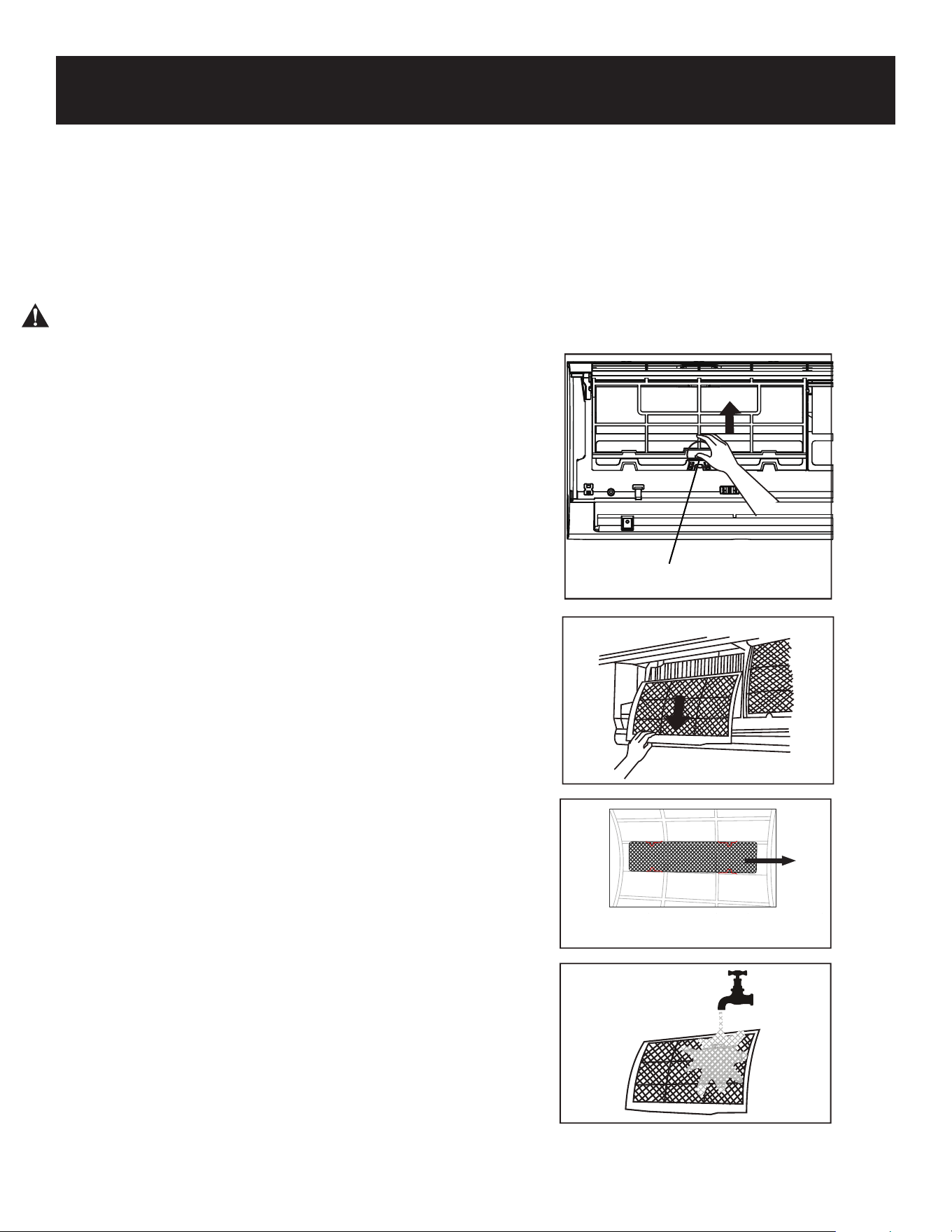
Page 86
LIMPIEZA Y CUIDADO
LIMPIEZA DE LA UNIDAD INTERIOR ANTES
DE LA LIMPIEZA O MANTENIMIENTO
APAGUE SIEMPRE EL SISTEMA DE AIRE
ACONDICIONADO Y DESCONECTE LA
FUENTE DE CORRIENTE ANTES DE
REALIZAR CUALQUIER OPERACIÓN DE
LIMPIEZA O MANTENIMIENTO.
PRECAUCIÓN
Utilice únicamente un paño suave y seco para
limpiar la unidad. Si la unidad está
especialmente sucia, puede utilizar un paño
empapado en agua tibia para limpiarla.
• No utilice productos químicos ni paños
tratados químicamente para limpiar la
unidad.
• No utilice benceno, disolvente de pintura,
polvo de pulir u otros disolventes para
limpiar la unidad. Pueden agrietar o
deformar la superficie de plástico.
• No utilice agua a más de 40°C (104°F)
para limpiar el panel frontal. Esto puede
causar que el panel se deforme o se
decolore.
LIMPIEZA DEL FILTRO
Un aire acondicionado obstruido puede
reducir la eficiencia de enfriamiento de su
unidad, y también puede ser malo para su
salud. Asegúrese de limpiar los filtros una vez
cada dos semanas.
1. Levante el panel frontal de la unidad
interior.
2. Primero presione la lengüeta en el extremo
del filtro para aflojar la hebilla, levántelo y
luego tire de él hacia usted.
3. Ahora tire del filtro hacia fuera.
4. Separe el filtro pequeño del grande. Limpie
este filtro con una aspiradora de mano.
5. Limpie el filtro de aire grande con agua
tibia y jabón. Asegúrese de utilizar un
detergente suave.
6. Enjuague el filtro con agua fresca, luego
sacuda el exceso de agua.
7. Séquelo en un lugar fresco y seco, y evite
exponerlo a la luz solar directa.
8. Cuando esté seco, vuelva a colocar el filtro
de aire en el filtro más grande y, a
continuación, deslícelo de nuevo en la
unidad interior.
9. Cierre el panel frontal de la unidad interior.
Retire el filtro de aire pequeño del más
grande.
Retire
Pestaña Filtro
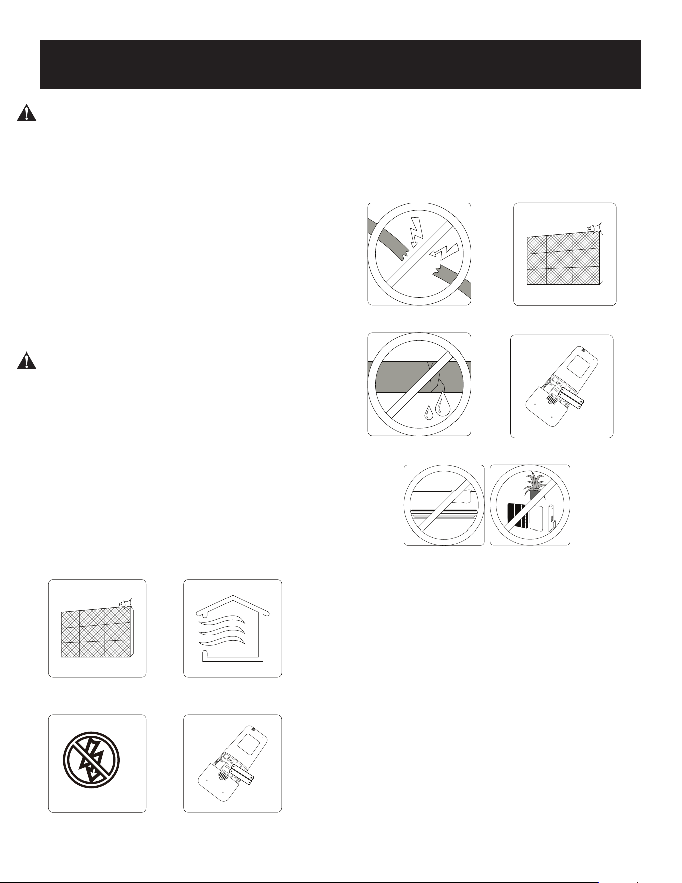
Page 87
LIMPIEZA Y CUIDADO
PRECAUCIÓN
• Antes de cambiar el filtro o limpiarlo,
apague la unidad y desconecte su fuente
de corriente.
• Cuando quite el filtro, no toque las partes
metálicas de la unidad. Los bordes
metálicos afilados pueden cortarle.
• No utilice agua para limpiar el interior de
la unidad interior. Esto puede destruir
el aislamiento y provocar una descarga
eléctrica.
• No exponga el filtro a la luz directa del
sol cuando se seque. Esto puede encoger
el filtro.
Mantenimiento - Largos periodos sin uso
Si tiene previsto no utilizar el aire
acondicionado durante un largo período de
tiempo, ¡haga lo siguiente!
Mantenimiento - Inspección previa a la
temporada
Después de largos periodos sin uso, o
antes de periodos de uso frecuente, haga lo
siguiente:
PRECAUCIÓN
• El mantenimiento y la limpieza de la
unidad exterior deben ser realizados
por un distribuidor autorizado o un
proveedor de servicios autorizado.
• Cualquier reparación de la unidad
debe ser realizada por un distribuidor
autorizado o un proveedor de
servicios autorizado.
Limpiar todos los filtros
Encienda la función VENTILADOR
hasta que la unidad se seque por
completo
Apague la unidad y desconecte
la alimentación.
Retire las baterías del
control remoto
Compruebe si hay cables
dañados
comprobar si hay fugas
Asegúrese de que nada bloquee todas las entradas y
salidas de aire.
Reemplace las baterías
Limpiar todos los filtros
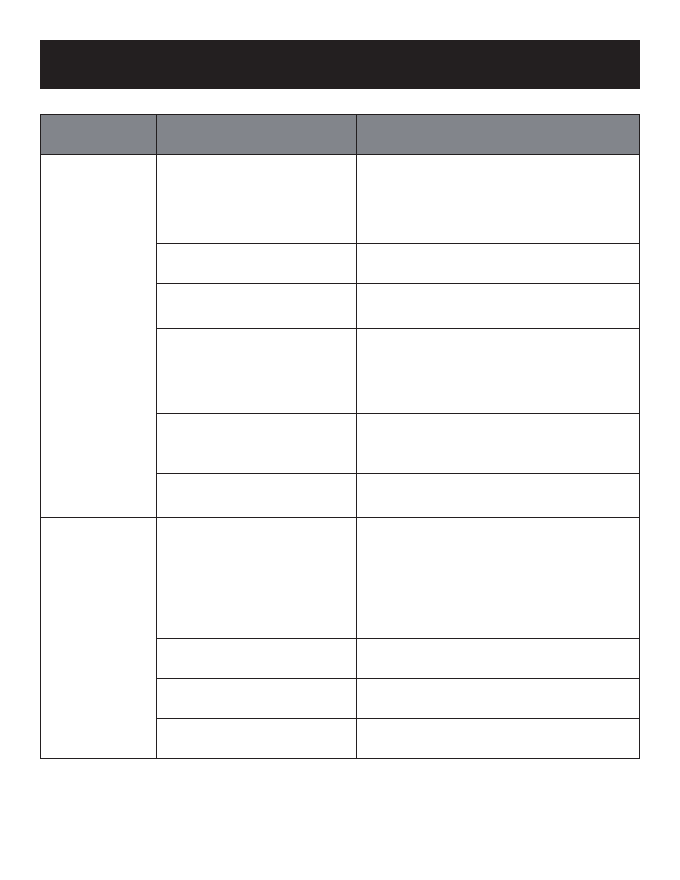
Page 88
RESOLUCIÓN DE PROBLEMAS Y GARANTÍA
Problema Causa Solución
Rendimiento de
refrigeración
deficiente
El ajuste de temperatura puede
ser superior a la temperatura
ambiente de la habitación.
Reduzca el ajuste de temperatura.
El intercambiador de calor de la
unidad interior o exterior está
sucio.
Limpie el intercambiador de calor afectado.
El filtro de aire está sucio.
Retire el filtro y límpielo siguiendo las
instrucciones.
La entrada o salida de aire de
cualquiera de las unidades está
bloqueada.
Apague la unidad, retire la obstrucción y
vuelva a encenderla.
Las puertas y ventanas están
abiertas.
Asegúrese de que todas las puertas y
ventanas están cerradas mientras utiliza la
unidad.
La luz solar genera un calor
excesivo.
Cierre las ventanas y cortinas durante los
periodos de mucho calor o sol brillante.
Hay demasiadas fuentes de
calor en la habitación (personas,
ordenadores, aparatos
electrónicos, etc.).
Reduzca la cantidad de fuentes de calor.
Bajo nivel de refrigerante
debido a una fuga de uso
prolongado.
Haga que un técnico de servicio cualificado
compruebe si hay fugas, vuelva a sellar si es
necesario y rellene de refrigerante.
La unidad no
funciona.
Fallo de corriente
Espere a que se restablezca el suministro
eléctrico.
La corriente está desconectada Conecte la corriente
Se ha quemado el fusible Sustituya el fusible
Las pilas del control remoto
están agotadas
Sustituya las pilas
Se ha activado la protección de
3 minutos de la unidad
Espere tres minutos después de reiniciar la
unidad
El temporizador está activado Apague el temporizador
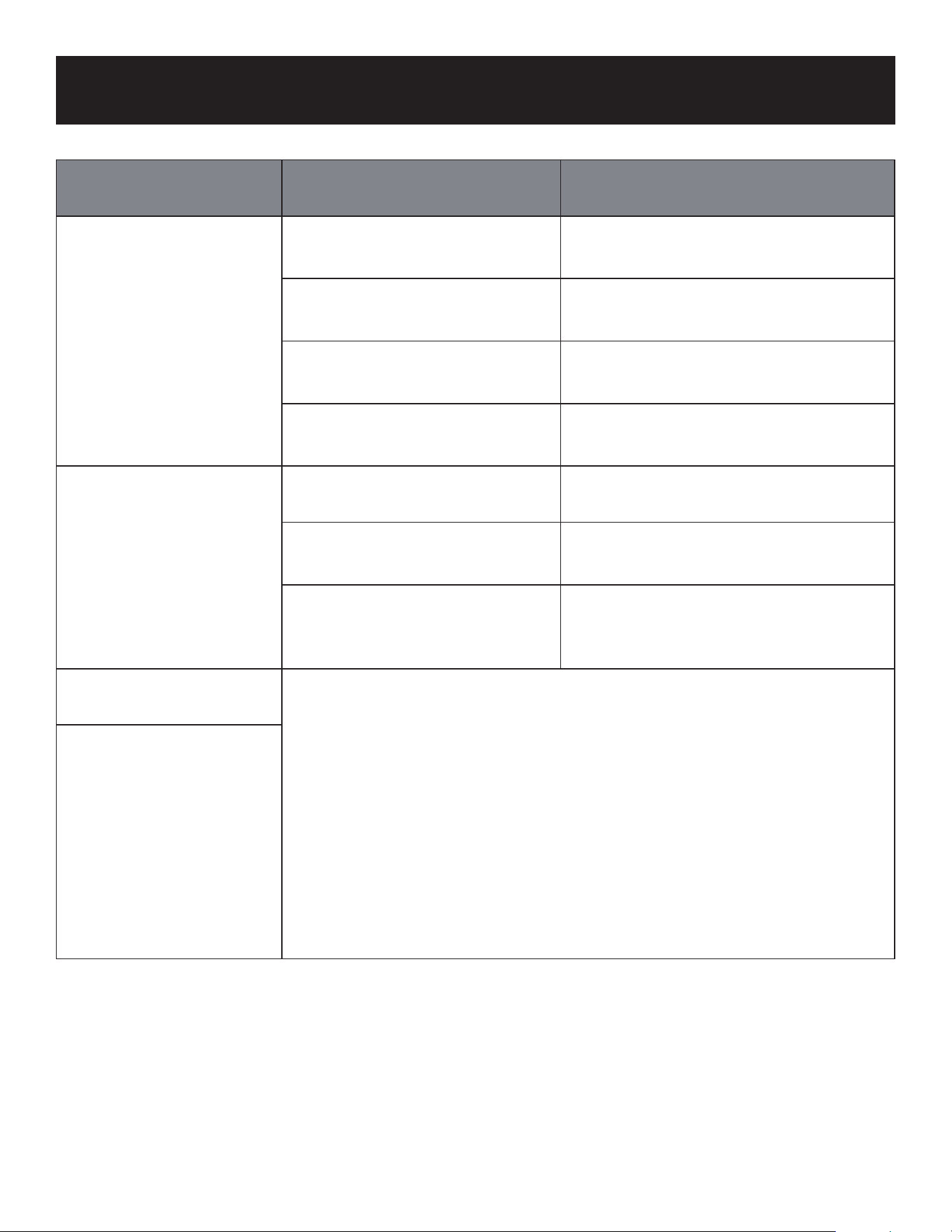
Page 89
RESOLUCIÓN DE PROBLEMAS Y GARANTÍA
Problema Causa Solución
La unidad arranca y se
detiene con frecuencia
Hay demasiado o muy poco
refrigerante en el sistema.
Haga que un técnico de servicio
cualificado compruebe si hay fugas y
recargue el sistema con refrigerante.
Ha entrado gas incompresible o
humedad en el sistema.
Haga que un técnico de servicio
cualificado evacúe y recargue el
sistema con refrigerante.
El compresor está averiado.
Puede ser necesario sustituir el
compresor. Llame a un técnico de
servicio cualificado.
El voltaje es demasiado alto o
demasiado bajo.
Haga que un técnico de servicio
calificado instale un manostato para
regular el voltaje.
Poor heating
performance
La temperatura exterior es
extremadamente baja.
Utilice un dispositivo de calefacción
auxiliar
Entra aire frío por puertas y
ventanas.
Asegúrese de que todas las puertas
y ventanas están dosificadas durante
el uso.
Hay poco refrigerante debido
a una fuga o a un uso pro-
longado.
Haga que un técnico de servicio
cualificado compruebe si hay fugas,
vuelva a sellar si es necesario y
rellene de refrigerante.
Las luces indicadoras
siguen parpadeando
La unidad puede dejar de funcionar o seguir funcionando de forma
segura. Si los indicadores luminosos siguen parpadeando o aparecen
códigos de error, espere unos 10 minutos. Es posible que el problema
se resuelva por sí solo. Si no es así, desconecte la corriente y vuelva a
conectarla. Encienda la unidad. Si el problema persiste, desconecte la
corriente y llame al Centro de Atención al Cliente BLACK+DECKER al
844-299-0879.
El código de error
aparece y comienza con
las siguientes letras en
la ventana de
visualización de la
unidad interior:
• E(x).P(X).F(x)
• EH(xX), EL(xx),
EC(xx)
• PH(xx), PL(xx),
PC(xx)

Page 90
RESOLUCIÓN DE PROBLEMAS Y GARANTÍA
SI EL AIRE ACONDICIONADO NO FUNCIONA:
A) Compruebe que el aire acondicionado ha sido instalado correctamente por un
instalador cualicado.
B) Compruebe si se ha fundido un fusible o se ha disparado el disyuntor principal.
C) Compruebe si la electricidad del interruptor principal de la unidad parece
funcionar.
D) Asegúrese de que ambas unidades están en posición vertical.
SI NADA DE LO ANTERIOR RESUELVE EL PROBLEMA, PÓNGASE EN CONTACTO
CON UN TÉCNICO CUALIFICADO.
ADVERTENCIA: NO INTENTE AJUSTAR O REPARAR EL AIRE ACONDICIONADO
USTED MISMO.
ANTES DE LLAMAR AL SERVICIO TÉCNICO
SERVICIO AL CLIENTE
IMPORTANTE
NO DEVUELVA ESTE PRODUCTO A LA TIENDA
Si tiene algún problema con este producto, póngase en contacto con
el Centro de Atención al Cliente de W Appliance Co. al 844-299-0879
PRUEBA DE COMPRA FECHADA, # DE MODELO Y # DE SERIE
REQUERIDOS PARA EL SERVICIO DE GARANTÍA

Page 91
RESOLUCIÓN DE PROBLEMAS Y GARANTÍA
GARANTÍA LIMITADA
Cualquier reparación, reemplazo o servicio de garantía, y
todas las preguntas acerca de este producto deben ser
dirigidas a W Appliance Co. al 844-299-0879 desde los
EE.UU. o Puerto Rico.
W Appliance Co. garantiza al comprador original que el
producto estará libre de defectos en materiales, piezas
y mano de obra durante el período designado para este
producto. La garantía comienza el día en que se instala el
producto y cubre hasta un período de 5 años de compresor
limitado/2 años de piezas limitadas (sólo defectos de
fabricación). W Appliance Co. se compromete, a su elección,
a sustituir el producto defectuoso por una unidad nueva o
refabricada equivalente a la adquirida originalmente durante
el período de garantía.
Exclusiones: Esta garantía no se aplica a lo siguiente.
1. Si la apariencia o el exterior del producto han sido
dañados o desgurados, alterados o modicados en
su diseño o construcción.
2. Si el número de serie original del producto ha sido
alterado o eliminado o no puede determinarse
fácilmente.
3. Si hay daños debidos a sobretensión de la línea
eléctrica, daños causados por el usuario en el cable
de corriente de CA o conexión a una fuente de
tensión inadecuada.
4. Si el daño se debe a un mal uso general, accidentes o
casos fortuitos.
5. Si la unidad no fue instalada por un técnico
autorizado.
6. Si los intentos de reparación son realizados por
agentes de servicio no autorizados, uso de piezas que
no sean genuinas o piezas obtenidas de personas que
no sean compañías de servicio autorizadas.
7. Si la instalación no cumplió con los códigos locales y
de construcción.
8. En unidades que han sido transferidas del propietario
original o que no se encuentran en la dirección de
instalación original.
9. En productos que hayan sido adquiridos como
reacondicionados, como nuevos, de segunda mano,
en condiciones “tal cual” o “venta nal”.
10. En productos utilizados en un entorno comercial o de
alquiler.
11. En productos utilizados en entornos distintos al uso
doméstico ordinario o utilizados de forma distinta a
las instrucciones proporcionadas.
12. Daños y perjuicios por llamadas al servicio técnico
por instalación incorrecta.
13. Los costes de mano de obra, transporte y envío
asociados a la sustitución de la unidad.
14. A las llamadas de servicio para instruirle en el uso de
su producto.
15. Llamadas al servicio técnico para reparar o sustituir
el fusible de la vivienda, restablecer el disyuntor o
corregir el cableado de la vivienda.
16. Costes de carga, recarga o eliminación de
refrigerante.
17. Piezas de instalación o suministros adquiridos por el
instalador o el agente de servicio.
LA REPARACIÓN O SUSTITUCIÓN SEGÚN LO DISPUESTO
EN ESTA GARANTÍA ES EL RECURSO EXCLUSIVO DEL
CLIENTE W APPLIANCE CO. NO SERÁ RESPONSABLE
DE NINGÚN DAÑO INCIDENTAL O CONSECUENTEF
NI DEL INCUMPLIMIENTO DE NINGUNA GARANTÍA
EXPRESA O IMPLÍCITA DE ESTE PRODUCTO, EXCEPTO
EN LA MEDIDA EN QUE LO PROHÍBA LA LEGISLACIÓN
APLICABLECUALQUIER GARANTÍA IMPLÍCITA DE
COMERCIABILIDAD DE IDONEIDAD PARA UN FIN
DETERMINADO DE ESTE PRODUCTO SE LIMITA A LA
DURACIÓN DE LA GARANTÍA.
Algunos estados no permiten la exclusión o limitación de
daños incidentales o consecuentes, o limitaciones en la
duración de la garantía. En estos casos, es posible que las
exclusiones o limitaciones anteriores no se apliquen en su
caso. Esta garantía le otorga derechos legales especícos y
es posible que también tenga otros derechos que varían de
un estado a otro.
Obtención del servicio: Para obtener servicio, literatura
del producto, suministros o accesorios por favor llame al
844-299-0879 para crear un ticket de cambio/reparación.
Asegúrese de proporcionar el recibo y la prueba de la fecha
de instalación original, el número de modelo y una breve
descripción del problema. Nuestro representante de servicio
al cliente se pondrá en contacto con usted o le enviará
instrucciones detalladas de devolución.
W Appliance Co. no garantiza que el aparato funcionará
correctamente en todas las condiciones ambientales, y no
ofrece ninguna garantía ni representación, ya sea implícita
o explícita, con respecto a la calidad, el rendimiento, la
capacidad comercial o la idoneidad para un propósito
particular distinto del propósito identificado en este manual
del usuario W Appliance Co. ha hecho todo lo posible para
garantizar que este manual del usuario sea preciso y declina
toda responsabilidad por cualquier inexactitud u omisión que
pueda haberse producido. La información contenida en este
manual del usuario está sujeta a cambios sin previo aviso y
no representa ningún compromiso por parte de W Appliance
Co. W Appliance Co. se reserva el derecho a realizar mejoras
en este manual del usuario y/o en los productos descritos
en este manual del usuario en cualquier momento y sin
previo aviso. Si encuentra información incorrecta, engañosa
o incompleta en este manual, póngase en contacto con
nosotros llamando al 844-299-0879.
W Appliance Co.
Nueva York, NY 10018

BLACK & DECKER, BLACK+DECKER los logotipos de BLACK & DECKER y
BLACK+DECKER y los nombres de los productos son marcas comerciales de
The Black &Decker Corporation, utilizadas bajo licencia. Todos los derechos
reservados.
El producto en esta caja puede diferir ligeramente del que aparece en la
foto. No afecta al funcionamiento. No todos los accesorios mostrados en la
fotografía están incluidos en este paquete.
Importado por W Appliance, Inc 1356 Broadway, New York, NY 10018
Octubre 2023 Impreso en China