

Quick Guide
Programmable DC Power Supply
HDP43XX/44XX Series
V 1.1

Quick Guide
2
Copyright Statement
Copyright
Qingdao Hantek Electronic Co., Ltd.
Statement
Qingdao Hantek Electronic Co., Ltd. reserves the right to amend this document without
prior notice. Qingdao Hantek Electronic Co., Ltd. promises that the information provided is
correct and reliable, but does not guarantee that this document is infallible. Please make
sure that the specifications of relevant technical documents used are the latest and valid
version yourself before using this product. If you require the cooperation of products,
patents or works of a third party when your company using the documents or products of
Qingdao Hantek Electronic Co., Ltd., your company shall be responsible for obtaining the
consent and authorization of the third party. The aforesaid consent and authorization are
not the responsibility of our company to guarantee.

Quick Guide
3
Technical Support
If you have any question or ambiguity in the process of using products of Qingdao Hantek
Electronic Co., Ltd., you can get the service and support through the following ways:
A: Please contact the local dealer of Qingdao Hantek Electronic Co., Ltd.;
B: Please contact the local office directly under Qingdao Hantek Electronic Co., Ltd;
C: Please contact the headquarters of Qingdao Hantek Electronic Co., Ltd.
Contact Method of our company:
Qingdao Hantek Electronic Co., Ltd.
http://www.hantek.com/en/index.html
Address: 35# Building No.780 Baoyuan Road, High-tech District, Qingdao China
Zip Code: 266114
Telephone: 0532-88705792
Fax: 0532-88705691
Email: [email protected]
Technical Support:
Telephone: 0532-88703687
Email: [email protected]

Quick Guide
4
Summary of general safety matters
General Safety Summary
Read the following safety precautions carefully to avoid injury and prevent damage to this
product or any product connected to this product. To avoid possible danger, be sure to use
this product as specified.
Avoid fire and personal injury.
Only professionally authorized personnel should perform repairs.
Use the correct power cord.
Use only the power cord specified for this product in your country.
Connect and disconnect properly.
Select the correct AC power input gear and input the AC voltage within its allowable range.
Please turn off the power before connecting to the output terminal. Before powering off the
instrument, disconnect the load it carries and then power off.
Ground the product.
To avoid electric shock, the product is grounded through the grounding conductor of the
power cord. The grounding conductor must be connected to ground. Before connecting the
input or output of the product, be sure to ground the product properly.
View all terminal ratings.
To avoid fire or the impact of excessive current, check all ratings and markings on the
product. Please consult the product manual for details on ratings before connecting the
product.
Use proper overvoltage protection.
Make sure that no over voltages (such as those caused by lightning) reach the product.
Otherwise, the operator may be exposed to electric shock.
Do not open the cover.
Do not operate the product with the cover or panel open.
Maintain proper ventilation.
Poor ventilation will increase the temperature of the instrument and cause damage to the
instrument. Good ventilation should be maintained during use, and the vents and fans
should be checked regularly.
Use a suitable fuse.

Quick Guide
5
Only use fuses specified for this product.
Avoid exposed circuits.
Do not touch exposed connectors and components after power is turned on.
Do not operate the product if you suspect it is malfunctioning.
If the user suspects that this product has been damaged, have it inspected by qualified
service personnel.
Do not operate in a humid environment.
To avoid the danger of short circuit or electric shock inside the instrument, do not operate
the instrument in a humid environment.
Do not operate in a flammable or explosive environment.
To avoid damage to the instrument or personal injury, do not operate the instrument in a
flammable or explosive environment.
Keep the surface of the product clean and dry.
To prevent dust or moisture in the air from affecting the performance of the instrument,
keep the product surface clean and dry.
Anti-static protection.
Static electricity can cause damage to the instrument. Test in an anti-static area whenever
possible. Before connecting the cable to the instrument, ground its inner and outer
conductors briefly to discharge static electricity.
Pay attention to handling safety.
In order to avoid the instrument falling down during transportation, which may cause
damage to the buttons, knobs, or interfaces on the instrument panel, please pay attention
to transportation safety.
Safety terms and symbols
Product terminology. The following terms may appear on the product:
DANGER
It indicates that if you do this, you may cause immediate damage to the user.
WARNING
It indicates that the user may not immediately harm the user if they do this.
CAUTION
It indicates that the user may cause damage to this product or other property if this operation is performed.
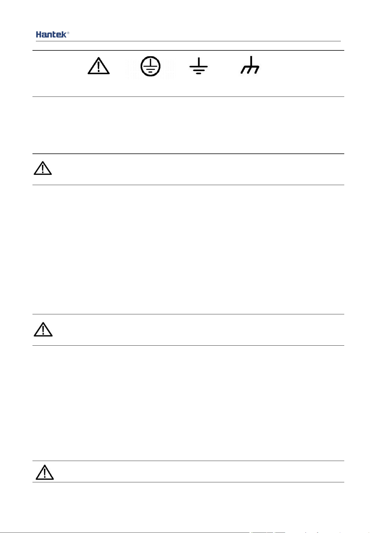
Product symbol. The following symbols may appear on the product:
Quick Guide
6
Safety Warning Protective Test Ground Shell Earth Terminal
Ventilation requirements
Make sure that the exhaust area is not blocked and has free flowing air. To ensure
adequate ventilation, when using the power supply in a workbench or rack, make sure that
there should be a gap of at least 10 cm on both sides, above, and behind it.
WARNING
Poor ventilation will increase the temperature of the instrument and cause damage to the instrument.
Good ventilation should be maintained during use. Regularly check the vents and fans.
Working environment
Temperature
During operation: 0
℃
to 50
℃
Non-operating: -40
℃
to 70
℃
Humidity
0℃ to 30℃: 95% relative humidity.
30
℃
to 40
℃
: 75% relative humidity.
40
℃
to 50
℃
: 45% relative humidity.
WARNING
To avoid the danger of short circuit or electric shock inside the instrument, do not operate the
instrument in a humid environment.
Altitude
When operating: below 3000 meters.
Non-operating: below 15000 meters.
Daily maintenance and cleaning
Daily maintenance
When storing or placing the oscilloscope, do not expose the LCD monitor to direct sunlight
for a long time.
CAUTION
To avoid damaging the oscilloscope or probe, do not place it in mist, liquid or solvent.
Quick Guide
7
Clean
According to the requirements of operating conditions, check the oscilloscope and probe
frequently. Please clean the outer surface of the instrument according to the following
steps:
Use a lint-free cloth to remove dust from the outside of the oscilloscope and probe. Be
careful not to scratch the smooth display filter.
Clean the oscilloscope with a soft cloth dampened with water. For more thorough cleaning,
use 75% isopropyl alcohol in water.
CAUTION
To avoid damaging the surface of the oscilloscope or probe, do not use any corrosive or chemical
cleaning agents.
Equipment recycling
Production of this equipment requires the extraction and use of natural resources. If this
product is not disposed of properly, some of the substances contained in the device may be
harmful to the environment or human health. To avoid release of harmful substances into
the environment and reduce the use of natural resources, it is recommended that this
product be recycled by appropriate methods to ensure that most materials can be reused
correctly.

Quick Guide
8
Contents
Copyright Statement
.............................................................................................................................
2
Technical Support
.................................................................................................................................
3
Summary of general safety matters
.....................................................................................................
4
General Safety Summary
.....................................................................................................................................................
4
Safety terms and symbols
...................................................................................................................................................
5
Ventilation requirements
....................................................................................................................................................
6
Working environment
.........................................................................................................................................................
6
Daily maintenance and cleaning
.........................................................................................................................................
6
Equipment recycling
............................................................................................................................................................
7
Contents
...............................................................................................................................................
8
Introduction
........................................................................................................................................
10
Chapter 1 Quick Start
.........................................................................................................................
11
1. Check before use
............................................................................................................................................................
11
1.1 Check the shipping package
....................................................................................................................................
11
1.2 Check the whole machine
.......................................................................................................................................
11
1.3 Check the accessories
..............................................................................................................................................
11
2. Front Panel Introduction
...............................................................................................................................................
11
3. Rear Panel Introduction
.................................................................................................................................................
13
Chapter 2 Getting Started
...................................................................................................................
14
1. Check the AC voltage range
...........................................................................................................................................
14
2. Check the fuse
................................................................................................................................................................
14
Chapter 3 Function Introduction
........................................................................................................
14
1. Output voltage and current
...........................................................................................................................................
14
2. Series output
..................................................................................................................................................................
15
3. Parallel output
...............................................................................................................................................................
16
4. Remote control
..............................................................................................................................................................
17
4.1 USB remote control
.................................................................................................................................................
17

Quick Guide
9
4.2 LAN remote control
.................................................................................................................................................
18
4.3 RS232/485 remote control
......................................................................................................................................
21
4.4 GPIB remote control
................................................................................................................................................
22
5. Utilities
...........................................................................................................................................................................
23
5.1 Store/recall
..............................................................................................................................................................
23
5.2 Setup
........................................................................................................................................................................
24
5.3 Error message
..........................................................................................................................................................
24
5.4 Capture
....................................................................................................................................................................
24
6. Lock/Unlock
...................................................................................................................................................................
25
Chapter 4 Troubleshooting
.................................................................................................................
26
Chapter 5 Performance Index
.............................................................................................................
27

Quick Guide
10
Introduction
HDP43XX/44XX is a programmable DC power supply. It has a user-friendly interface
design, excellent performance indicators, a variety of communication interfaces to meet the
different needs of users, and a variety of analysis functions to meet the diverse needs of
users.
Main Feature:
4.3-inch TFT display
Series and parallel output
High performance: accuracy, transient response and linear adjustment rate
Built-in Chinese and English help system
Digital IO interface, support trigger input/output function
Support SCPI programmable command control
Waveform display function, real-time dynamic display of output voltage/current
waveform, with the digital display of voltage, current and power values, so that users
can see the output status and trend of the instrument at a glance
OV/OC/OT protection function
Keyboard lock function to prevent misoperation
Voltage tracking function
Delay switch function
One-key restore preset state function
Support store and recall
A variety of interface configurations to meet the needs of users
Support U disk storage
Quick Guide
11
Chapter 1 Quick Start
Taking the three-channel power supply as an example, this chapter will briefly describe and
introduce the front panel, rear panel, user interface, help system, and precautions when
using the instrument for the first time. In this way, users can become familiar with this series
of power supplies in the shortest possible time.
1. Check before use
1.1 Check the shipping package
If you find that the packaging carton or foam protection pad is severely damaged, please
keep it until the whole machine and accessories pass the electrical and mechanical tests.
1.2 Check the whole machine
If you find that the appearance of the instrument is damaged, the instrument is not working
properly, or the performance test fails, please contact the dealer responsible for this
business.
1.3 Check the accessories
Please check the accessories according to the product packing list. If you find the
accessories are missing or damaged, please contact the dealer responsible for this
business.
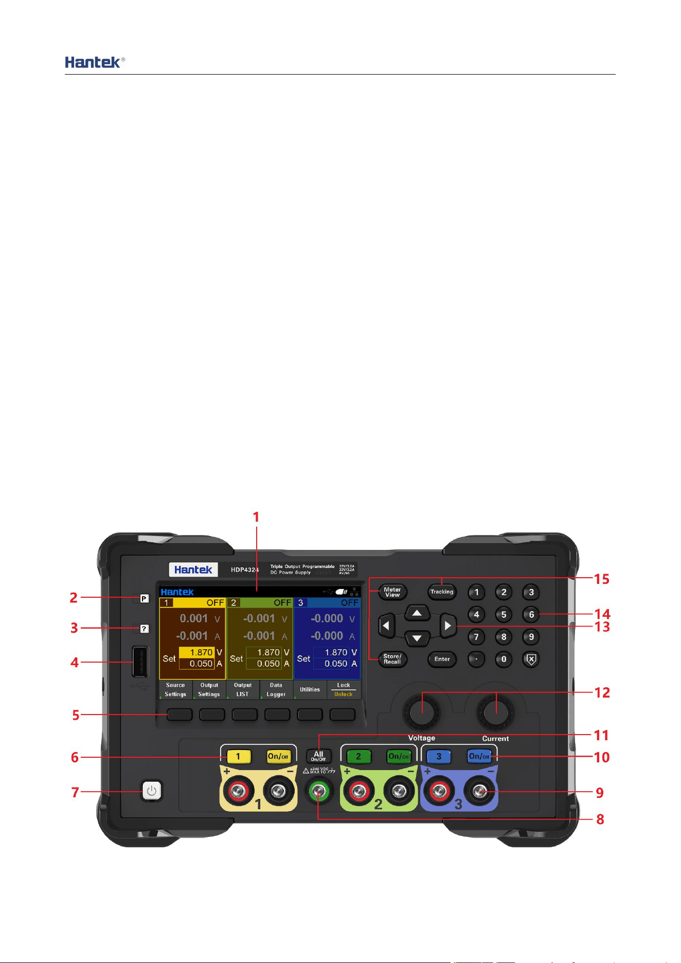
2. Front Panel Introduction

Quick Guide
12
1. LCD Display screen
2. Restore default settings
3. Help
Used to quickly get relevant help on the use of the instrument.
4. USB Host
Used for firmware upgrade or external file saving.
5. Auxiliary function soft keys
Operate according to the screen display.
6. Channel Button
Press to select the current channel. Then you can directly set the voltage and current of the
current channel.
7. Power button
8. Common ground terminal
9. Output terminal
10. Output control keys
Turn the output on or off.
11. ALL ON/OFF key
Turn on all or turn off all output channels.
12. Voltage/current adjustment knob
Finely adjust the voltage/current, and the adjustment accuracy is 1mV/1mA.
13. Arrow keys
Use the arrow keys to move the cursor position up, down, left, and right.
14. Numeric keypad
Enter the value directly, press the "Enter" key to confirm, and press the "×" key to delete.
15. Function keys
Meter View: Display the Meter View of the selected channel.
Tracking: Turn on or off the tracking mode of channel 1 and channel 2.
Store/Recall: Open the store/recall menu.
Quick Guide
13
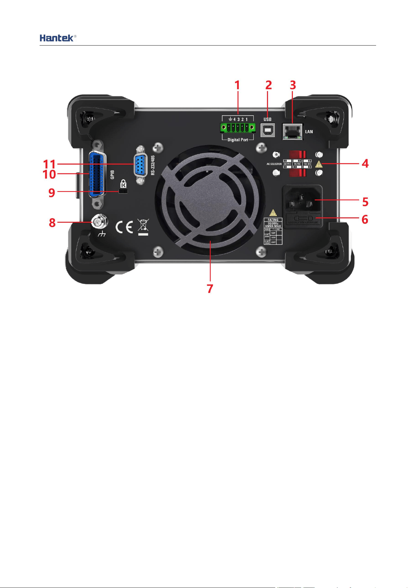
3. Rear Panel Introduction
1. Digital IO interface
2. USB interface
3. LAN interface
4. AC selector
5. Power jack
6. Fuse holder
7. Exhaust fan
8. Ground reference point
9. Safety lock
10. GPIB interface
11. RS-232/485 interface
Quick Guide
14
Chapter 2 Getting Started
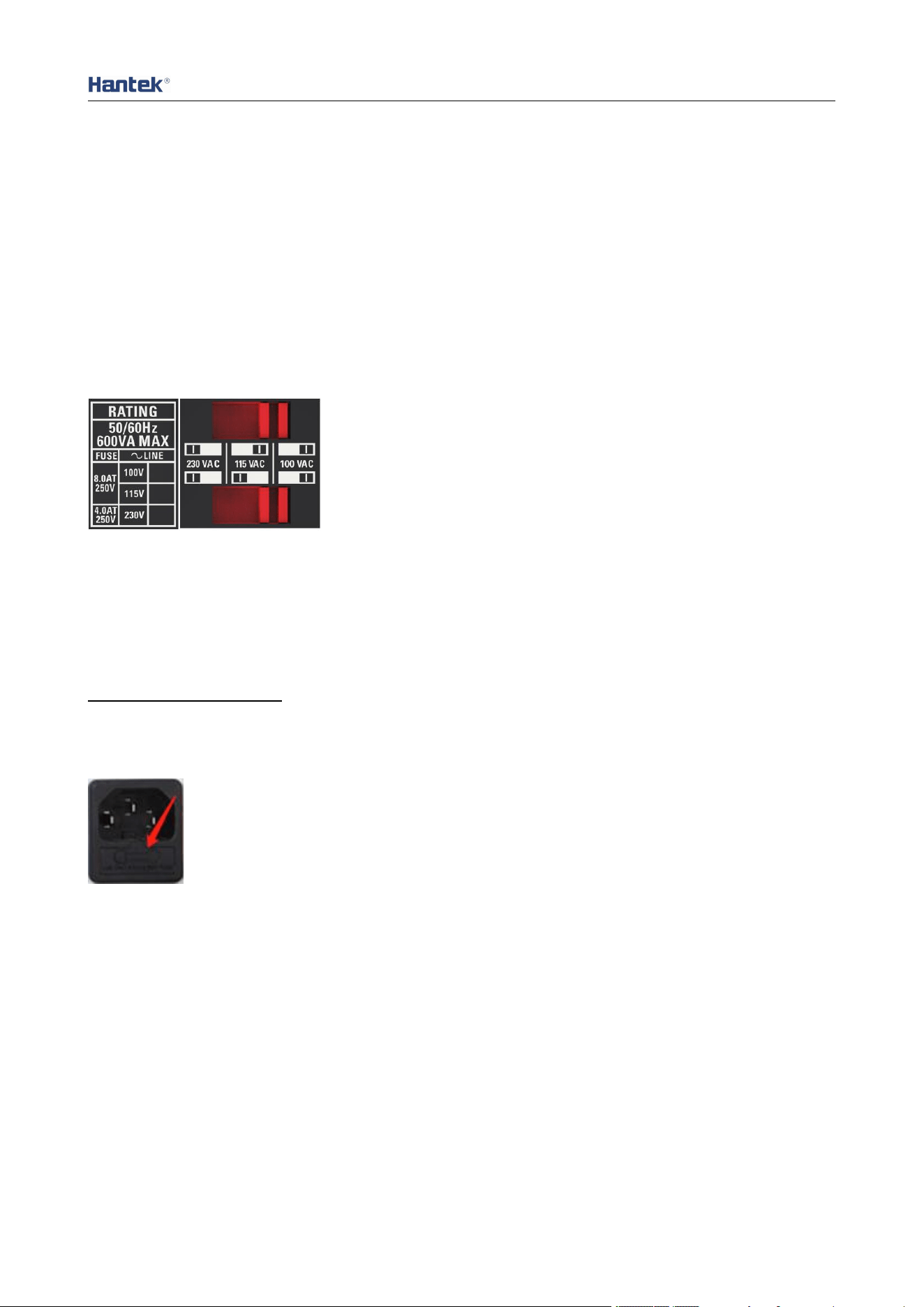
1. Check the AC voltage range
This series of programmable DC power supplies support various specifications of AC
power input, and users can choose the appropriate input gear according to actual needs.
The user must check the gear position of the AC voltage selector on the rear panel of the
power supply before using it, and the input voltage must be within the allowable range
(±10%) of the gear position. The corresponding relationship between the voltage selector
on the rear panel of the power supply and the allowable input voltage is as follows:
2. Check the fuse
The instrument has been installed with the specified fuse at the factory. Before use, please
check whether the fuse type matches the AC voltage range. If it does not match or the fuse
is blown, replace the fuse according to the specifications.
Steps to replace the fuse:
1. Turn off the power and unplug the power cord;
2. Lift out the fuse holder;
3. Remove the broken fuse and install a new one;
4. Put the fuse holder back into the slot.
Chapter 3 Function Introduction
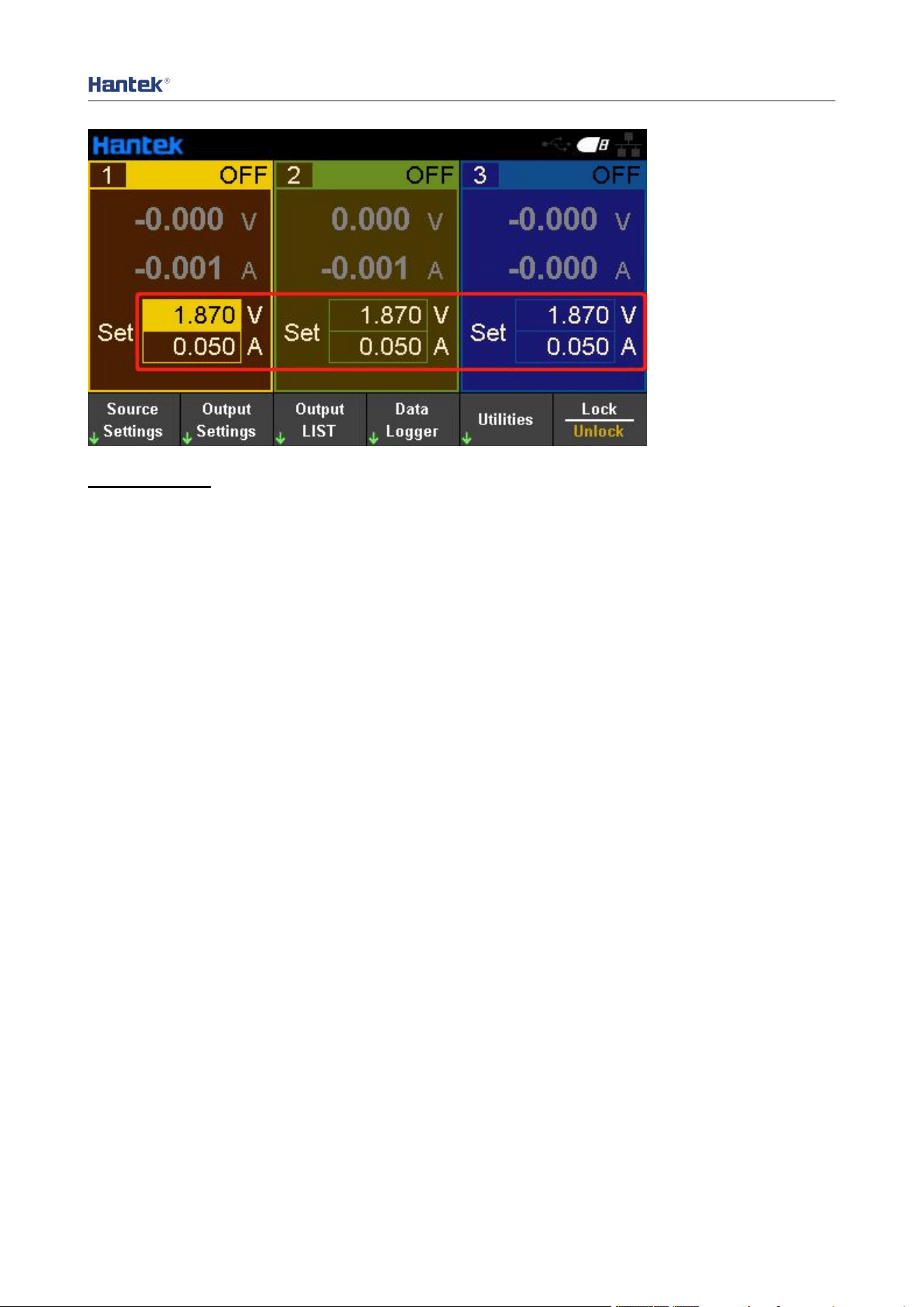
1. Output voltage and current
The output voltage and current can be directly input in the main interface, or set in "Source
Settings" and "Meter View".
Quick Guide
15
Setting steps:
1. Select the output channel
Press the digital channel button on the front panel, or continuously press the left "
◁
" and
right "▷" arrows to select the output channel to be set.
2. Set voltage/current:
Press the arrow keys to select voltage or current, use the numeric keyboard or knob to set
the value, press "×" to delete, and press "Enter" to confirm and exit editing.
3. Turn on the output
Press the "On/Off" key to turn on the output.
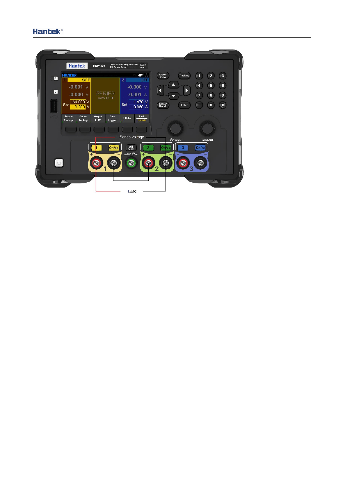
2. Series output
Press Output Settings->Operation Mode to select Series, which can be set as serial output.
In series mode, the channels are internally connected in series to form a single output. The
channel 2 window of the main interface displays "SERIES with CH1". Channel 1 is the
master and channel 2 is the slave. The "+" terminal of channel 1 and the "-" terminal of
channel 2 are the two output terminals of the series circuit. The output voltage is twice the
set voltage of channel 1, and the output current is the set current of channel 1. The external
wiring method of series mode is as follows:
Quick Guide
16
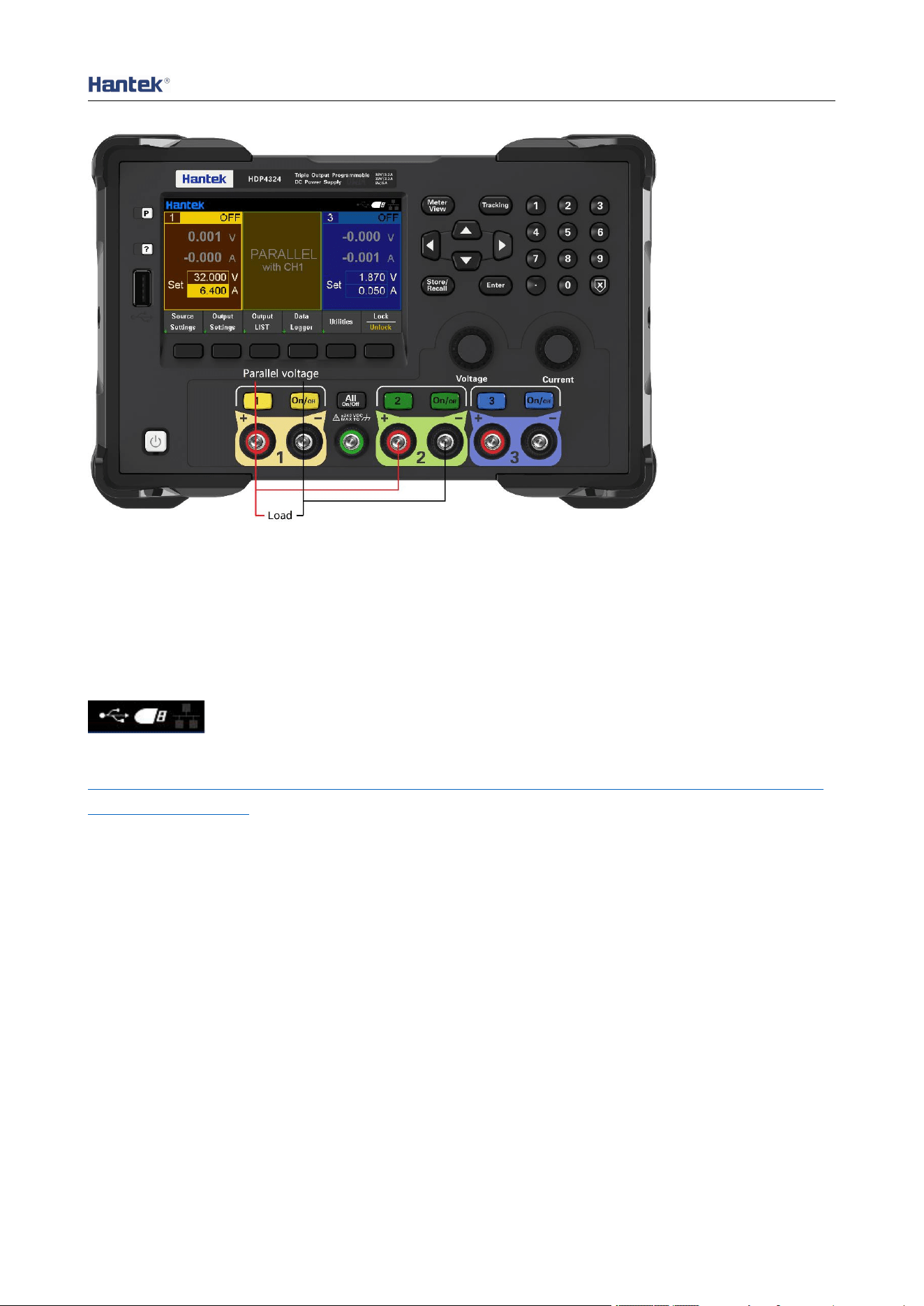
3. Parallel output
Press Output Settings->Operation Mode to select Parallel, which can be set as parallel
output.
In parallel mode, the channels are internally connected in parallel to form a single output.
The channel 2 window of the main interface displays "PARALLEL with CH1". Channel 1 is
the master and channel 2 is the slave. The "+" and "-" binding posts of channel 1 are the
two output terminals of the parallel circuit. The output current is twice the set current of
channel 1, and the output voltage is the set voltage of channel 1. The external wiring
method of parallel mode is as follows:
Quick Guide
17
4. Remote control
4.1 USB remote control
Use the USB cable to connect the USB port on the back of the computer to the USB port on
the rear panel of the power supply. At this time, the USB connected logo is displayed on the
upper right corner of the main interface of the power supply.
Download and install the IO software from the following address:
https://www.keysight.com/main/software.jspx?id=2175637&nid=-11143.0.00&pageMode=
CV&lc=eng&cc=CA
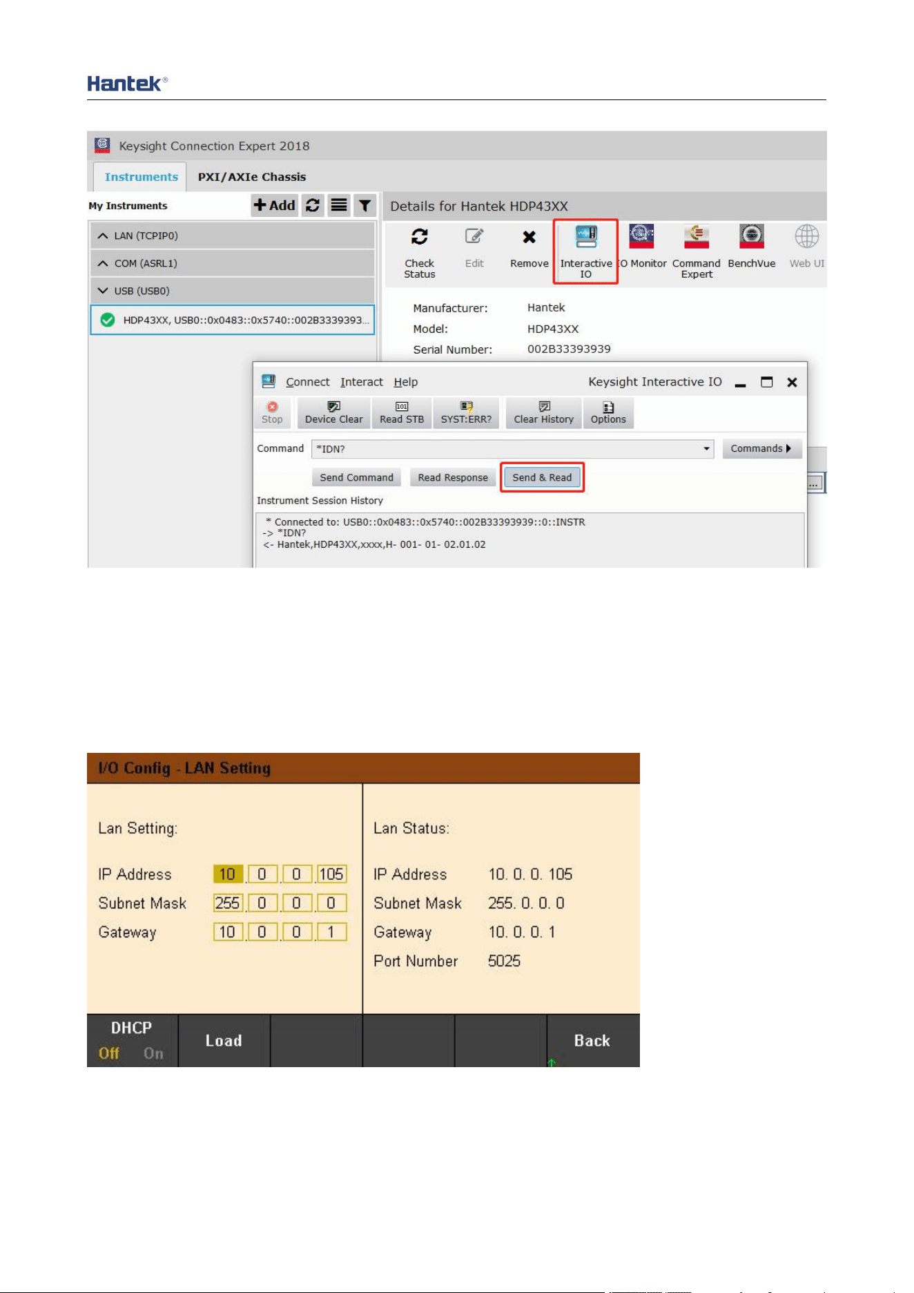
Open the IO software, find the device, and send an instruction to see if the communication
is normal. After normal communication is obtained, SCPI commands can be used to control
the power output.
E.g:
OUTP On, (@1) Set the channel 1 output on.
Volt 5, (@1) Set the voltage of channel 1 to 5V.
Meas:volt? (@1) View the output voltage value of channel 1.
Quick Guide
18
4.2 LAN remote control
Connect the back-end network port of the computer to the network port on the rear panel of
the power supply with a LAN network cable.
Utility→I/O Config→LAN Settings to set the power supply LAN parameter.
Press Load menu to load settings, as shown in the figure below:
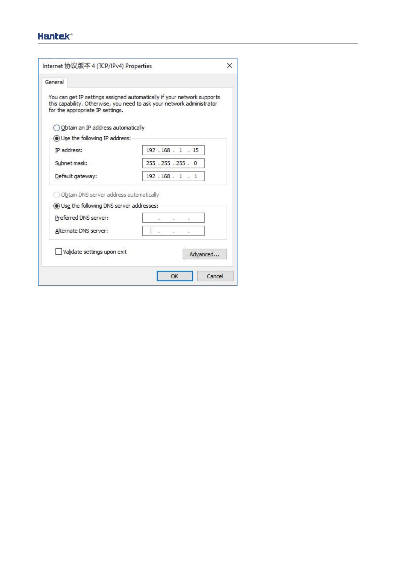
Please configuration of computer IP and other information manually. Set computer Ethernet
properties:
Quick Guide
19
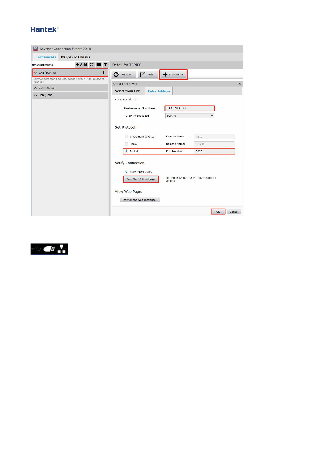
After the connection is successful, open the IO software and the device will appear in the
LAN list. If the device does not appear, you can manually add the device, enter the device's
IP address and protocol, test the VISA address, and click OK to add a new device.
Quick Guide
20
After a successful connection, the network port icon in the upper right corner of the main
interface is displayed as follows:
As with USB remote control, after obtaining normal communication, you can use SCPI
commands to control the power output.
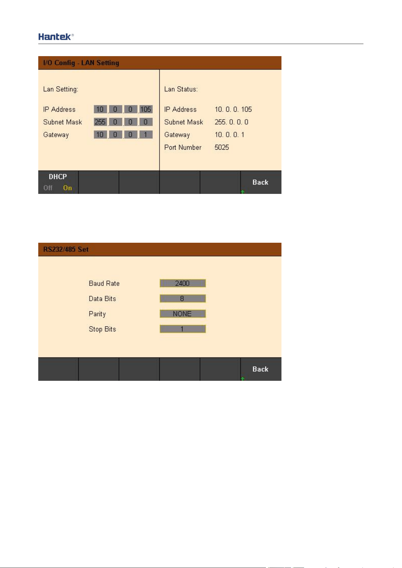
If there is a DHCP server in the LAN, you can open the DHCP function, and the instrument
will automatically obtain IP and other information from the DHCP server without manual
setup.
Quick Guide
21
Note: If there is no DHCP server on the LAN, you must configure IP and other information
manually.
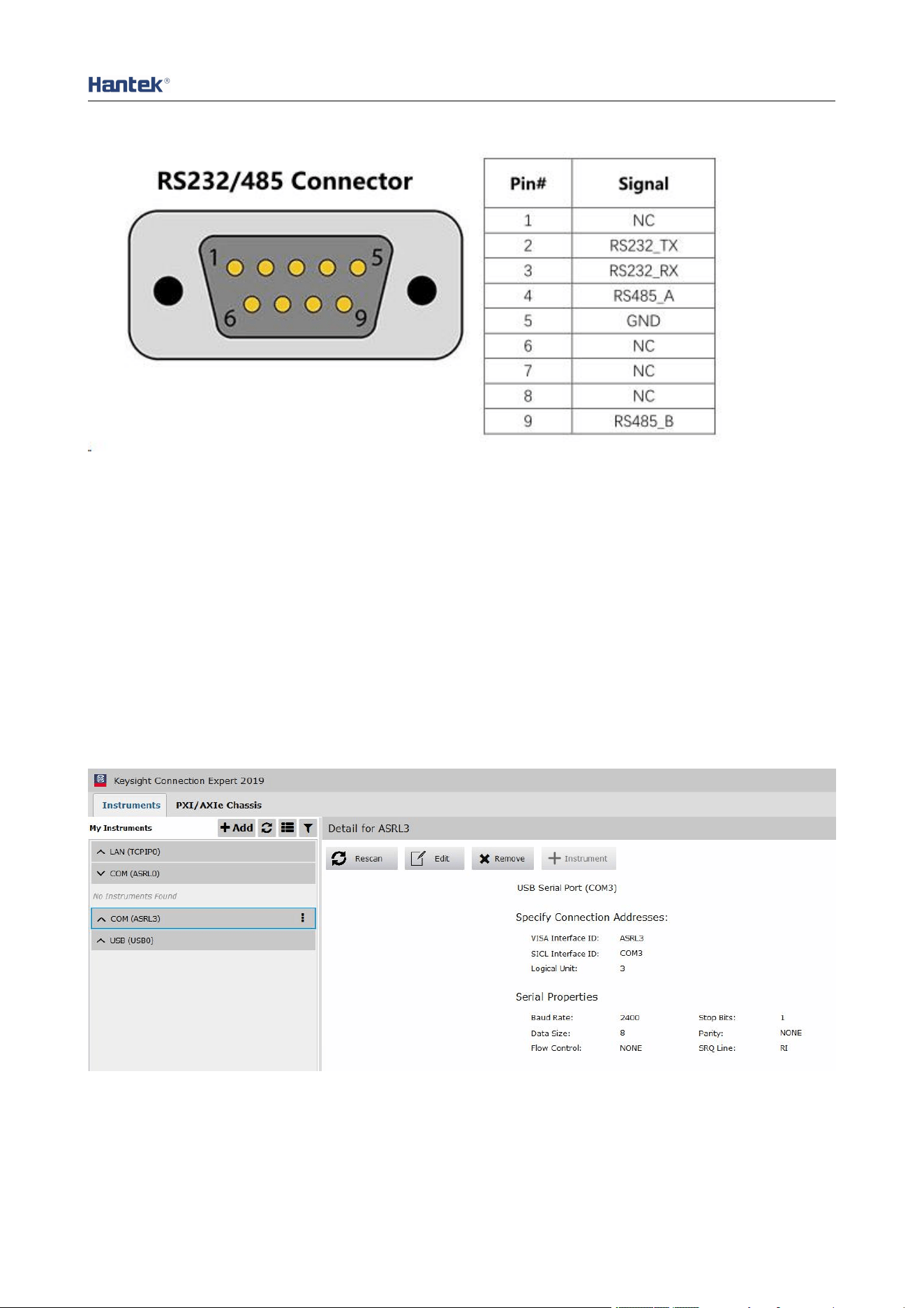
4.3 RS232/485 remote control
Each parameter is unchanged by default.
Pay attention to the wiring:
Pin2 is RS232_TX, Pin3 is RS232_RX, Pin4 is RS485_A, Pin9 is RS485_B.
Quick Guide
22
Open the IO software, select to add a device, set the corresponding baud rate, test the
VISA address, and click OK to add a new device.
As with USB remote control, after obtaining normal communication, you can use SCPI
commands to control the power output.
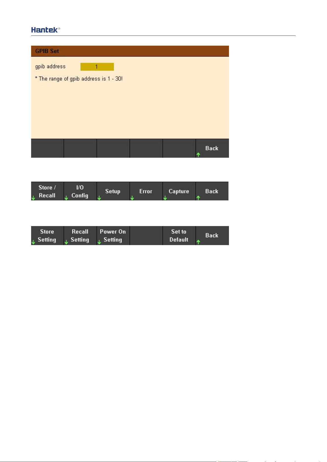
4.4 GPIB remote control
Utility->I/O Config->GPIB to open GPIB window. Use the numeric keypad to set the address of
GPIB and press ENTER to confirm.
Quick Guide
23
5. Utilities
5.1 Store/recall
Store/Recall can store and recall settings as volatile settings, such as: voltage and current
values, OVP, OCP, output coupling, output status, operation mode, list output, trigger
settings, data recording, key tone, Help language etc.
5.1.1 Store Setting
Store Settings: Used to select internal storage or external storage.
Select Internal, the settings will be saved in the power memory. Up to 10 states can be
stored as State 0-State 9. You can choose whether to set it to "Power-on State". Press
"Store" to save this setting.
Select External, the settings will be saved to the external storage device. First insert the
USB storage device into the USB port on the front panel, press "Enter" under "File" to edit
the file name, press "Done" to save and exit, and press "Store" to execute the save. The file
will be saved in the .csv format to the root directory of the external storage device.
5.1.2 Recall setting
Used to select to recall from internal or from external. Same as store settings: select the
location, state name or external .csv setting file of the file to be recalled, press "Enter" to
confirm, and press "Recall" to execute recall.

Quick Guide
24
5.1.3 Power-on setting
Press "Power On Setting" to select a state to be automatically recalled after power-on. You
can choose the default settings or user-specified settings. Press "SetPwrOn" to save the
settings. Users can also check "
□
Set this as power-on state." in "Store Settings" to set.
5.1.4 Restore default settings
Press "Set to Defaults" to restore the default settings.
5.2 Setup
5.2.1 Help language
The default is English, press “Enter” to switch to Chinese.
5.2.2 Sound switch
Press “Enter” to switch the key tone on or off.
5.2.3 Firmware upgrade
Select the channel to be upgraded and press “Start” to start the upgrade.
5.2.4 Calibration
The instrument has been calibrated before leaving the factory, and the user does not need
to calibrate again. If you really need to calibrate, you can use SCPI commands to recall the
calibration program.
5.3 Error message
Error displays the error information of the instrument. The error information list is arranged
in the order in which it was generated, that is, the most recent error is displayed at the top.
Press "Next" to view the next page.
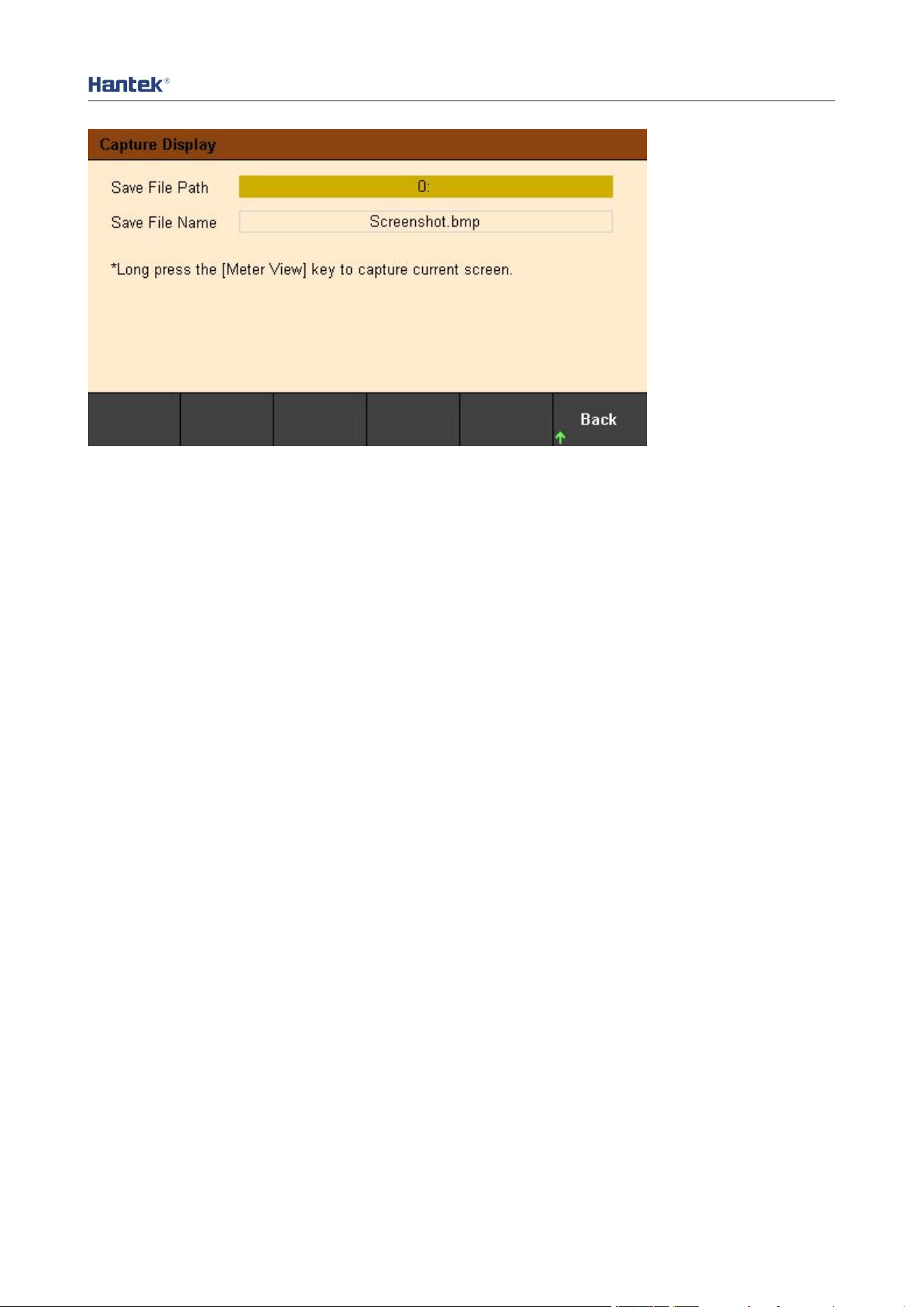
5.4 Capture
Capture can set the properties of the screenshot file, including the save path and file name.
The default picture format is .bmp.
Long press the "Meter View" button for 3 seconds to perform the screenshot operation, and
the screenshot file is automatically saved to the external storage device.
Quick Guide
25
6. Lock/Unlock
Long press the "Lock/Unlock" key to lock the front panel, short press this key to cancel the
lock.
When the front panel is locked, the lock icon will be displayed on the top of the main screen,
and the icon will disappear after unlocking.

Quick Guide
26
Chapter 4 Troubleshooting
The following faults may occur during the use of this series of programmable DC power
supplies. Users can refer to the following methods to deal with. If the fault still exists, please
contact Hantek and provide the equipment information of the instrument (How to obtain: ?
->About).
1. The instrument cannot be turned on.
(1) Check whether the power cord is properly connected.
(2) Check whether the power switch on the front panel is turned on.
(3) Unplug the power cord, check whether the AC selector is in the correct position, whether
the specifications of the fuse are correct and whether it is intact. If you need to replace the
fuse, please refer to the "Steps to replace the fuse".
(4) If the problem persists, please contact Hantek.
2. The constant voltage output is abnormal.
(1) Check whether the maximum output power of the selected gear meets the load
requirements.
(2) Whether the cables connecting the load and the power supply are short-circuited, and
whether they are in good contact.
(3) Check whether there is a problem with the load.
(4) Check whether the current setting value of this gear is appropriate. If it is too low, you
can increase the current setting value appropriately.
(5) If the problem still cannot be solved, please contact Hantek.
3. The constant current output is abnormal.
(1) Check whether the maximum output power of the selected gear meets the load
requirements.
(2) Whether the cables connecting the load and the power supply are disconnected and
whether they are in good contact.
(3) Check whether there is a problem with the load.
(4) Check whether the voltage setting value of this gear is appropriate. If it is too low, you
can increase the voltage setting value appropriately.
(5) If the problem still cannot be solved, please contact Hantek.
4. The U disk cannot be recognized correctly.
(1) Check whether the U disk can work normally.
(2) Make sure that the USB flash drive is used. This instrument does not support hard drive
USB flash drives.
(3) After restarting the instrument, insert the U disk to check.
(4) If the USB flash drive still cannot be used normally, please contact Hantek.
Quick Guide
27
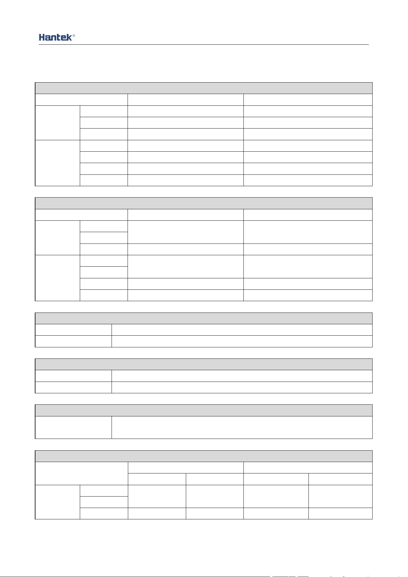
Chapter 5 Performance Index
DC output (0℃~40℃)
Channel
Voltage
Current
HDP43XX
CH1
32V
3.2A
CH2
32V
3.2A
CH3
8V
5A
HDP44XX
CH1
32V
3.2A
CH2
32V
3.2A
CH3
8V
2A
CH4
16V
1.5A
Series and parallel output
Channel
Series
Parallel
HDP43XX
CH1
64V,3.2A
32V,6.4A
CH2
CH3
—
—
HDP44XX
CH1
64V,3.2A
32V,6.4A
CH2
CH3
—
—
CH4
—
—
Load Regulation ±(% of output + offset)
Voltage
<0.01%+2mV
Current
<0.01%+250μA
Line Regulation ±(% of output + offset)
Voltage
<0.01%+2mV
Current
<0.01%+250μA
Ripple and noise (20Hz to 20MHz)
Normal mode
voltage
<350μVrms /2mVpp
Accuracy(25℃±5℃) ±(% of output + offset)
Channel
Programming
Readback
Voltage
Current
Voltage
Current
HDP43XX
CH1
0.05%+10mV
0.2%+5mA
0.05%+10mV
0.2%+5mA
CH2
CH3
0.1%+5mV
0.1%+10mA
0.1%+5mV
0.1%+10mA
Quick Guide
28
HDP44XX
CH1
0.05%+10mV
0.2%+5mA
0.05%+10mV
0.2%+5mA
CH2
CH3
0.1%+5mV
0.1%+10mA
0.1%+5mV
0.1%+10mA
CH4
Transient response time
The output current from full load to half load, or from half load to full load, the time for the
output voltage to recover to within 15mV is less than 50μs.
Mechanical
Size
232*153*392mm
Weight
HDP43XX
9.15Kg
HDP44XX
9.45Kg
Power supply
AC input (50Hz~60Hz)
100Vac±10%,115Vac±10%,230Vac±10%(Maximum 250Vac)
Maximum input power
600VA
Interface
USB Device
1 piece
USB Host
1 piece
LAN
1 piece
Digital IO
1 piece
RS-232/485
1 piece (Option)
GPIB
1 piece (Option)
Surroundings
Cooling method
Air-cooled
Operating temperature
0℃~50℃
Storage temperature
-40℃~70℃
Humidity
0℃~30℃: ≤95% relative humidity
30℃~40℃: ≤75% relative humidity
40℃~50℃: ≤45% relative humidity
Altitude
Below 3000 meters