

AXIS I7020 Network Inter com
T able of Contents
Setup overview . . . . . . . . . . . . . . . . . . . . . . . . . . . . . . . . . . . . . . . . . . . . . 3
Get started . . . . . . . . . . . . . . . . . . . . . . . . . . . . . . . . . . . . . . . . . . . . . . . . 4
Find the device on the network . . . . . . . . . . . . . . . . . . . . . . . . . . . . . . . . . . . . 4
Open the device's web interface . . . . . . . . . . . . . . . . . . . . . . . . . . . . . . . . . . . . 4
Create an administrator account . . . . . . . . . . . . . . . . . . . . . . . . . . . . . . . . . . . 4
Secure passwords . . . . . . . . . . . . . . . . . . . . . . . . . . . . . . . . . . . . . . . . . . . . . . . 4
V erify that no one has tampered with the device software . . . . . . . . . . . . . . 5
Congure your device . . . . . . . . . . . . . . . . . . . . . . . . . . . . . . . . . . . . . . . . 6
Set up direct SIP (P2P) . . . . . . . . . . . . . . . . . . . . . . . . . . . . . . . . . . . . . . . . . . . 6
Set up SIP through a server (PBX) . . . . . . . . . . . . . . . . . . . . . . . . . . . . . . . . . . 6
Include video stream from nearby camera in SIP call . . . . . . . . . . . . . . . . . . . 7
Create a contact . . . . . . . . . . . . . . . . . . . . . . . . . . . . . . . . . . . . . . . . . . . . . . . . 7
Congure the call button . . . . . . . . . . . . . . . . . . . . . . . . . . . . . . . . . . . . . . . . . 8
Use D TMF to unlock the door for a visitor . . . . . . . . . . . . . . . . . . . . . . . . . . . . 8
Allow credential holders to open the door . . . . . . . . . . . . . . . . . . . . . . . . . . . . 9
Set up rules for events . . . . . . . . . . . . . . . . . . . . . . . . . . . . . . . . . . . . . . . . . . . 10
The web interface . . . . . . . . . . . . . . . . . . . . . . . . . . . . . . . . . . . . . . . . . . . 11
Status . . . . . . . . . . . . . . . . . . . . . . . . . . . . . . . . . . . . . . . . . . . . . . . . . . . . . . . . 1 1
Video . . . . . . . . . . . . . . . . . . . . . . . . . . . . . . . . . . . . . . . . . . . . . . . . . . . . . . . . . 12
Communication . . . . . . . . . . . . . . . . . . . . . . . . . . . . . . . . . . . . . . . . . . . . . . . . . 19
Reader . . . . . . . . . . . . . . . . . . . . . . . . . . . . . . . . . . . . . . . . . . . . . . . . . . . . . . . . 23
Audio . . . . . . . . . . . . . . . . . . . . . . . . . . . . . . . . . . . . . . . . . . . . . . . . . . . . . . . . . 24
Recordings . . . . . . . . . . . . . . . . . . . . . . . . . . . . . . . . . . . . . . . . . . . . . . . . . . . . . 25
Apps . . . . . . . . . . . . . . . . . . . . . . . . . . . . . . . . . . . . . . . . . . . . . . . . . . . . . . . . . . 26
System . . . . . . . . . . . . . . . . . . . . . . . . . . . . . . . . . . . . . . . . . . . . . . . . . . . . . . . . 26
Maintenance . . . . . . . . . . . . . . . . . . . . . . . . . . . . . . . . . . . . . . . . . . . . . . . . . . . 42
Learn more . . . . . . . . . . . . . . . . . . . . . . . . . . . . . . . . . . . . . . . . . . . . . . . . 43
V oice over IP (V oIP) . . . . . . . . . . . . . . . . . . . . . . . . . . . . . . . . . . . . . . . . . . . . . . 43
NA T traversal . . . . . . . . . . . . . . . . . . . . . . . . . . . . . . . . . . . . . . . . . . . . . . . . . . . 44
Cybersecurity . . . . . . . . . . . . . . . . . . . . . . . . . . . . . . . . . . . . . . . . . . . . . . . . . . . 45
Applications . . . . . . . . . . . . . . . . . . . . . . . . . . . . . . . . . . . . . . . . . . . . . . . . . . . . 45
Specications . . . . . . . . . . . . . . . . . . . . . . . . . . . . . . . . . . . . . . . . . . . . . . 46
Product overview . . . . . . . . . . . . . . . . . . . . . . . . . . . . . . . . . . . . . . . . . . . . . . . . 46
Front panel indicators and controls . . . . . . . . . . . . . . . . . . . . . . . . . . . . . . . . . 46
LED indicators . . . . . . . . . . . . . . . . . . . . . . . . . . . . . . . . . . . . . . . . . . . . . . . . . . 47
SD card slot . . . . . . . . . . . . . . . . . . . . . . . . . . . . . . . . . . . . . . . . . . . . . . . . . . . . 47
Buttons . . . . . . . . . . . . . . . . . . . . . . . . . . . . . . . . . . . . . . . . . . . . . . . . . . . . . . . 47
Connectors . . . . . . . . . . . . . . . . . . . . . . . . . . . . . . . . . . . . . . . . . . . . . . . . . . . . 47
Connect equipment . . . . . . . . . . . . . . . . . . . . . . . . . . . . . . . . . . . . . . . . . 50
Relay powered by P oE (12V) . . . . . . . . . . . . . . . . . . . . . . . . . . . . . . . . . . . . . . . 50
Relay powered by separate power supply . . . . . . . . . . . . . . . . . . . . . . . . . . . . 50
P otential - free relay . . . . . . . . . . . . . . . . . . . . . . . . . . . . . . . . . . . . . . . . . . . . . . 51
12V Fail - secure lock powered by P oE from intercom . . . . . . . . . . . . . . . . . . . 51
12V Fail - secure lock powered by external power supply . . . . . . . . . . . . . . . . . 51
Clean your device . . . . . . . . . . . . . . . . . . . . . . . . . . . . . . . . . . . . . . . . . . . 53
T roubleshooting . . . . . . . . . . . . . . . . . . . . . . . . . . . . . . . . . . . . . . . . . . . . 54
Reset to factory default settings . . . . . . . . . . . . . . . . . . . . . . . . . . . . . . . . . . . 54
AXIS OS options . . . . . . . . . . . . . . . . . . . . . . . . . . . . . . . . . . . . . . . . . . . . . . . . 54
Check the current AXIS OS version . . . . . . . . . . . . . . . . . . . . . . . . . . . . . . . . . . 54
Upgrade AXIS OS . . . . . . . . . . . . . . . . . . . . . . . . . . . . . . . . . . . . . . . . . . . . . . . . 54
T echnical issues, clues, and solutions . . . . . . . . . . . . . . . . . . . . . . . . . . . . . . . . 55
P erformance considerations . . . . . . . . . . . . . . . . . . . . . . . . . . . . . . . . . . . . . . . 56
Contact support . . . . . . . . . . . . . . . . . . . . . . . . . . . . . . . . . . . . . . . . . . . . . . . . . 56
Safety information . . . . . . . . . . . . . . . . . . . . . . . . . . . . . . . . . . . . . . . . . . 57
Hazard levels . . . . . . . . . . . . . . . . . . . . . . . . . . . . . . . . . . . . . . . . . . . . . . . . . . . 57
Other message levels . . . . . . . . . . . . . . . . . . . . . . . . . . . . . . . . . . . . . . . . . . . . . 57
2
AXIS I7020 Network Inter com
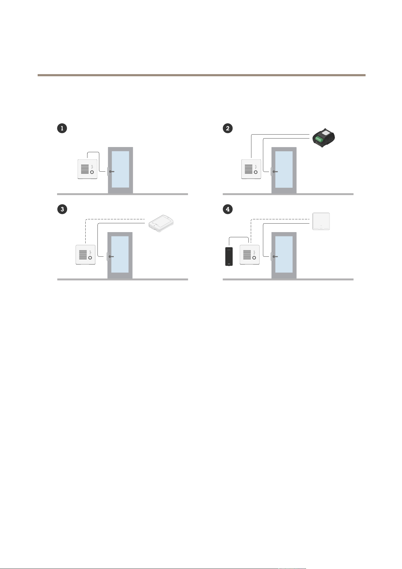
Setup overview
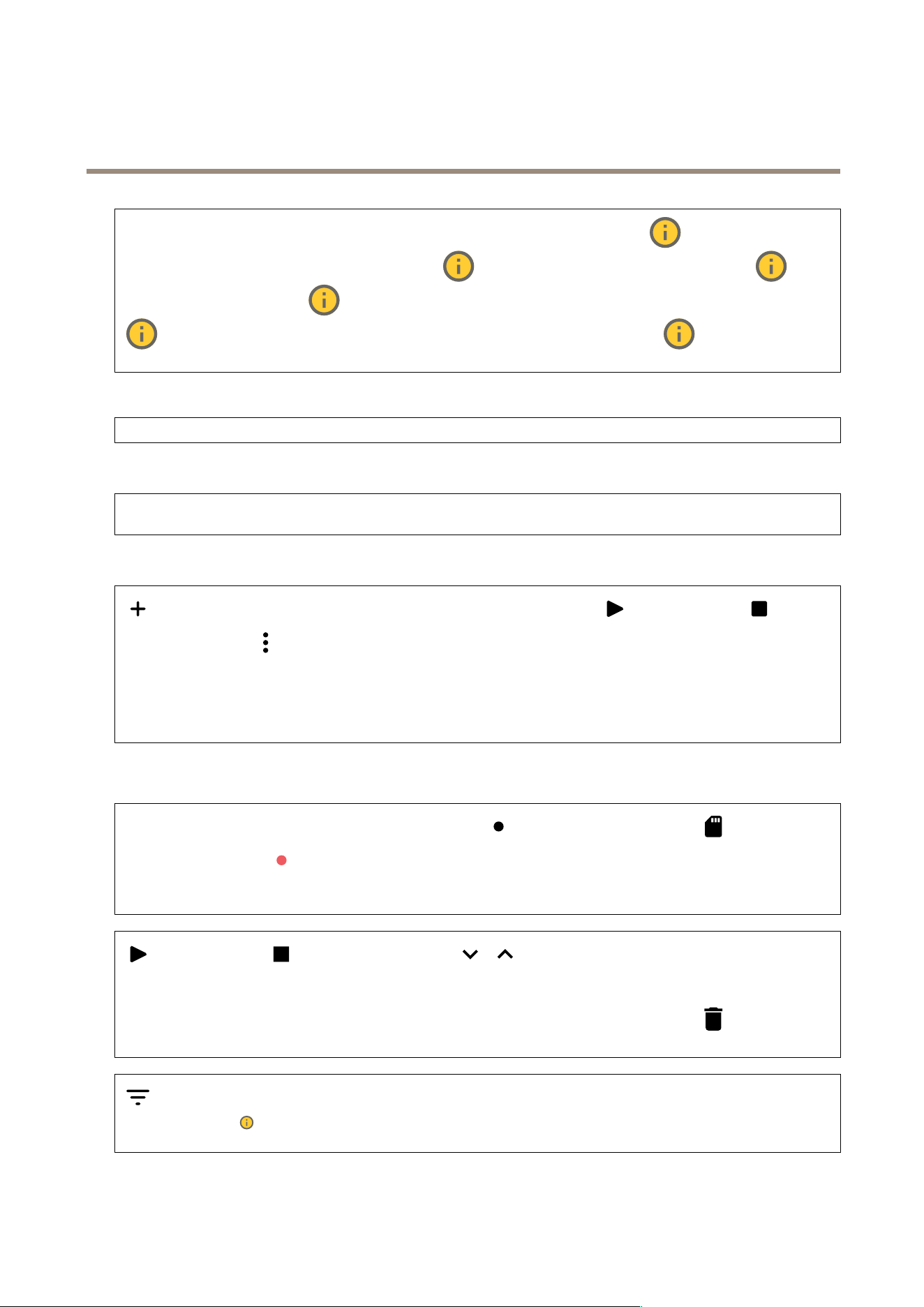
Setup overview
1
Intercom
2
Intercom combined with AXIS A980 1
3
Intercom combined with AXIS A9 16 1
4
Intercom combined with a reader and an access control system
3

AXIS I7020 Network Inter com
Get started
Get started
Find the device on the network
T o nd Axis devices on the network and assign them IP addresses in Windows®, use AXIS IP Utility or AXIS Device Manager . Both
applications are free and can be downloaded from axis.com/support .
For more information about how to nd and assign IP addresses, go to How to assign an IP address and access your device .
Browser support
Y ou can use the device with the following browsers:
Chrome
T M
Firefox
®
Edge
T M
Safari
®
Windows
®
recommended
recommended
macOS
®
recommended recommended
Linux
®
recommended recommended
Other operating systems *
*T o use AXIS OS web interface with iOS 15 or iP adOS 15, go to Settings Settings
Settings
> >
>
Safari Safari
Safari
> >
>
Advanced Advanced
Advanced
> >
>
Experimental Experimental
Experimental
Features Features
Features
and disable
NSURLSession W ebsocket.
If you need more information about recommended browsers, go to AXIS OS P ortal .
Open the device's web interface
1. Open a browser and type the IP address or host name of the Axis device.
If you do not know the IP address, use AXIS IP Utility or AXIS Device Manager to nd the device on the network.
2. T ype the username and password. If you access the device for the rst time, you must create an administrator account. See .
For descriptions of all the controls and options in the device’s web interface, see .
Create an administrator account
The rst time you log in to your device, you must create an administrator account.
1. Enter a username.
2. Enter a password. See .
3. Re - enter the password.
4. Accept the license agreement.
5. Click Add account .
Important
The device has no default account. If you lose the password for your administrator account, you must reset the device. See .
4

AXIS I7020 Network Inter com
Get started
Secure passwords
Important
Axis devices send the initially set password in clear text over the network. T o protect your device after the rst login, set
up a secure and encrypted HTTPS connection and then change the password.
The device password is the primary protection for your data and services. Axis devices do not impose a password policy as they
may be used in various types of installations.
T o protect your data we strongly recommend that you:
• Use a password with at least 8 characters, preferably created by a password generator .
• Don’t expose the password.
• Change the password at a recurring interval, at least once a year .
V erify that no one has tampered with the device software
T o make sure that the device has its original AXIS OS, or to take full control of the device after a security attack:
1. Reset to factory default settings. See .
After the reset, secure boot guarantees the state of the device.
2. Congure and install the device.
5

AXIS I7020 Network Inter com
Configur e your device
Configur e your device
This section covers all the important congurations that an installer needs to do to get the product up and running after the
hardware installation has been completed.
Set up direct SIP (P2P)
V oIP (V oice over IP) is a group of technologies that enables voice and multimedia communication over IP networks. For more
information, see .
In this device V oIP is enabled through the SIP protocol. For more information about SIP , see
There are two types of setups for SIP . Direct or peer - to - peer (P2P) is one of them. Use peer - to - peer when the communication is
between a few user agents within the same IP network and there is no need for extra features that a PBX - server could provide. For
information on how to set it up, see .
1. Go to Communication > SIP > Settings and select Enable SIP .
2. T o allow the device to receive incoming calls, select Allow incoming calls .
NO NO
NO
TICE TICE
TICE
When you allow incoming calls, the device accepts calls from any device connected to the network. If the device is accessible
from a public network or the internet, we recommend you not to allow incoming calls.
3. Click Call handling .
4. In Calling timeout , set the number of seconds that a call will last before it ends if there is no answer .
5. If you have allowed incoming calls, set the number of seconds before timeout for incoming calls in Incoming call timeout .
6. Click P orts .
7. Enter the SIP port number and TLS port number .
Note
• SIP port – for SIP sessions. Signalling trafc through this port is non - encrypted. The default port number is 5060.
• TLS port – for SIPS and TLS secured SIP sessions. Signalling trafc through this port is encrypted with T ransport Layer
Security (TLS). The default port number is 506 1.
• RTP start port – the port used for the rst RTP media stream in a SIP call. The default start port is 4000. Some rewalls can
block RTP trafc on certain port numbers. The port number must be between 1 0 24 and 65535.
8. Click NA T traversal .
9. Select the protocols you want to enable for NA T traversal.
Note
Use NA T traversal when the device is connected to the network from behind a NA T router or a rewall. For more information
see .
1 0. Click Save .
Set up SIP through a server (PBX)
V oIP (V oice over IP) is a group of technologies that enables voice and multimedia communication over IP networks. For more
information, see .
In this device, V oIP is enabled through the SIP protocol. For more information about SIP , see
6

AXIS I7020 Network Inter com
Configur e your device
There are two types of setups for SIP . A PBX server is one of them. Use a PBX server when the communication should be between an
innite number of user agents within and outside the IP network. Additional features could be added to the setup depending on
the PBX provider . For more information, see .
1. Request the following information from your PBX provider:
- User ID
- Domain
- P assword
- Authentication ID
- Caller ID
- Registrar
- RTP start port
2. Go to Communication > SIP > Accounts and click + Add account .
3. Enter a Name for the account.
4. Select Registered .
5. Select a transport mode.
6. Add the account information from the PBX provider .
7. Click Save .
8. Set up the SIP settings in the same way as for peer - to - peer , see . Use the RTP start port from the PBX provider .
Include video stream from nearby camera in SIP call
If you have an Axis camera mounted close to the intercom, you can include the video stream from the camera in your intercom SIP
and VMS calls.
Requirements
An Axis camera with H.264 and 1280x720, 800x800, or 640x480 resolution.
T o connect the intercom to the camera:
1. Go to System > Edge - to - edge > P airing .
2. Under Camera pairing , enter the address, username and password for the Axis camera.
3. Click Connect .
Create a contact
This example explains how to create a new contact in the contact list. Before you start, enable SIP in Communication > SIP .
T o create a new contact:
1. Go to Communication > Contact list .
2. Click + Add contact .
3. Enter the rst and last name of the contact.
4. Enter the contact’s SIP address.
7

AXIS I7020 Network Inter com
Configur e your device
Note
For information about SIP addresses, see .
5. Select the SIP account to call from.
Note
Availability options are dened in System > Events > Schedules .
6. Choose the contact’s Availability . If there’s a call when the contact isn’t available, the call gets canceled unless a there’s
a fallback contact.
Note
A fallback is a contact, to whom the call gets forwarded if the original contact doesn’t reply or isn’t available.
7. In Fallback , select None .
8. Click Save .
Congure the call button
By default, the call button is congured to make VMS (video management software) calls. If you want to keep this conguration, you
just need to add the Axis intercom to the VMS.
This example explains how to set up the system to call a contact in the contact list when a visitor presses the call button.
1. Go to Communication > Calls > Call button .
2. Under Recipients , remove VMS .
3. Under Recipients , select an existing or create a new contact.
T o disable the call button, turn off Enable call button .
Use D TMF to unlock the door for a visitor
When a visitor makes a call from the intercom, the person who answers can use the Dual - T one Multi - Frequency signaling (D TMF)
of his SIP device to unlock the door . The door controller unlocks and locks the door .
This example explains how to:
• dene the D TMF signal in the intercom
• set up the intercom to:
- request the door controller to unlock the door , or
- unlock the door using the internal relay .
Y ou make all settings in the intercom’s webpage.
Before you start
• Allow SIP calls from the device and create a SIP account. See and .
Dene the D TMF signal in the intercom
1. Go to Communication > SIP > D TMF .
2. Click + Add sequence .
3. In Sequence , enter 1 .
8

AXIS I7020 Network Inter com
Configur e your device
4. In Description , enter Unlock door .
5. In Accounts , select the SIP account.
6. Click Save .
Set up the intercom to unlock the door using the internal relay
7. Go to System > Events > Rules and add a rule.
8. In the Name eld, enter D TMF unlock door .
9. From the list of conditions, under Call , select D TMF and Unlock door .
1 0. From the list of actions, under I/O , select T oggle I/O once .
1 1. From the list of ports, select Relay 1 .
12. Change Duration to 00:00:0 7 , which means that the door is open for 7 seconds.
13. Click Save .
Allow credential holders to open the door
With Entry list, you can make it possible for credential holders to use their card or PIN to trigger actions, such as opening a door . This
example explains how to add a credential holder who can use their card to open the door 1 0 times.
Prerequisites
• Make sure the correct chip type is active in Reader > Chip types .
T urn on Entry list and add a credential holder:
1. Go to Reader > Entry list .
2. T urn on Use Entry list .
3. Click + Add credential holder .
4. Enter the credential holder's rst and last name. The rst name must be unique.
5. Select Card .
6. Swipe the credential holder's card on the device and click Get latest .
7. K eep the event condition Access granted .
8. Under V alid to , select Number of times .
9. In Number of times , enter 1 0 .
1 0. Click Save .
Create a rule:
1. Go to System > Events .
2. Under Rules , click + Add a rule .
3. In Name , enter Open door .
4. In the list of conditions, select Entry list > Access granted .
5. In the list of actions, select I/O > T oggle I/O once .
9

AXIS I7020 Network Inter com
Configur e your device
6. In the list of ports, select Door .
7. Under State , select Active .
8. Set the duration to 00:00:0 7 .
9. Click Save .
Set up rules for events
Y ou can create rules to make your device perform an action when certain events occur . A rule consists of conditions and actions.
The conditions can be used to trigger the actions. For example, the device can start a recording or send an email when it detects
motion, or show an overlay text while the device is recording.
T o learn more, check out our guide Get started with rules for events .
T rigger an action
1. Go to System > Events and add a rule. The rule denes when the device will perform certain actions. Y ou can set
up rules as scheduled, recurring, or manually triggered.
2. Enter a Name .
3. Select the Condition that must be met to trigger the action. If you specify more than one condition for the rule, all of the
conditions must be met to trigger the action.
4. Select which Action the device should perform when the conditions are met.
Note
If you make changes to an active rule, the rule must be turned on again for the changes to take effect.
1 0
AXIS I7020 Network Inter com
The web inter face
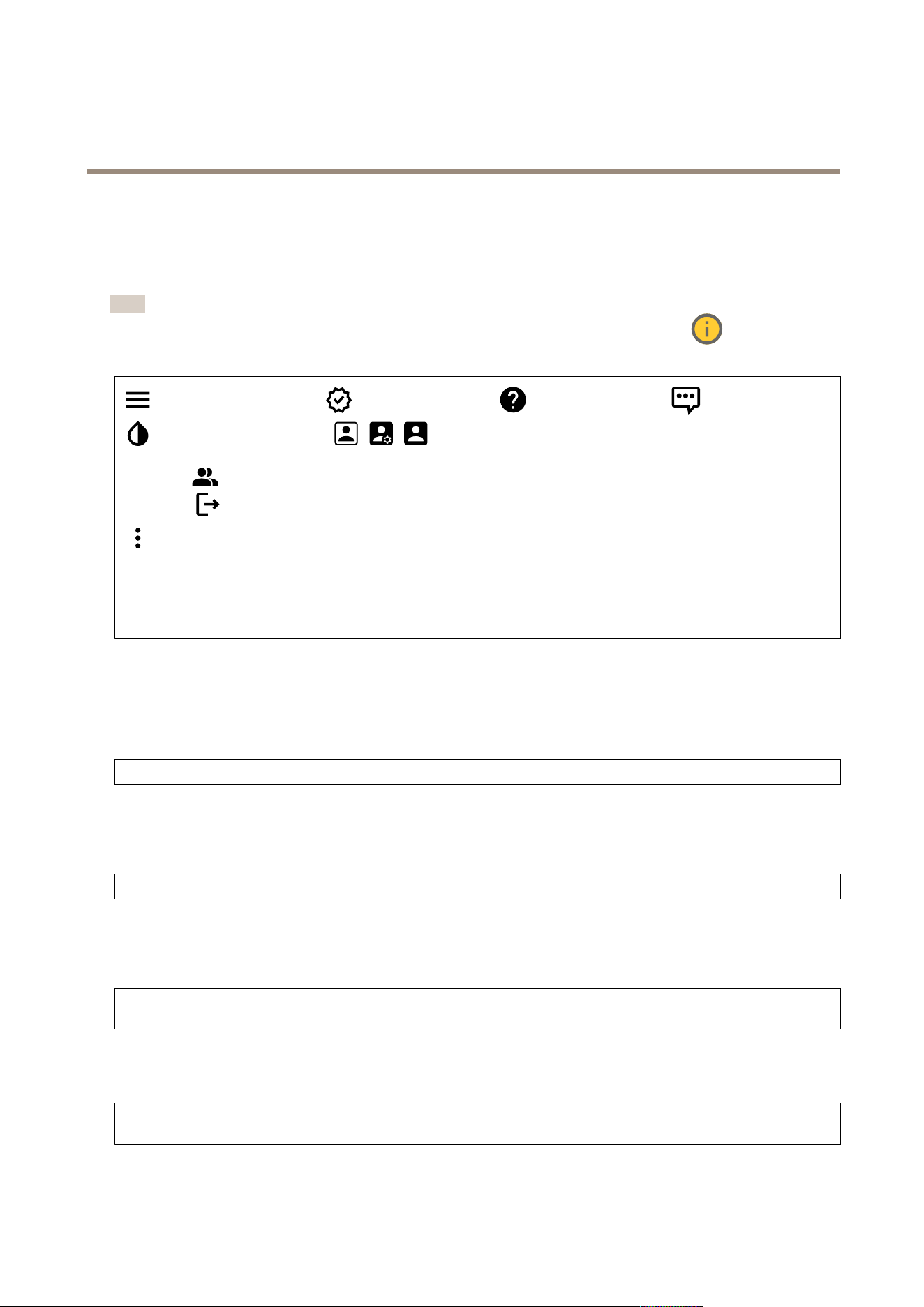
The web inter face
T o reach the device’s web interface, type the device’s IP address in a web browser .
Note
Support for the features and settings described in this section varies between devices. This icon indicates that
the feature or setting is only available in some devices.
Show or hide the main menu. Access the release notes. Access the product help. Change the language.
Set light theme or dark theme. The user menu contains:
• Information about the user who is logged in.
• Change account : Log out from the current account and log in to a new account.
• Log out : Log out from the current account.
The context menu contains:
• Analytics data : Accept to share non - personal browser data.
• Feedback : Share any feedback to help us improve your user experience.
• Legal : View information about cookies and licenses.
• About : View device information, including AXIS OS version and serial number .
• Legacy device interface : Change the device’s web interface to the legacy version.
Status
Device info
Shows the device information, including AXIS OS version and serial number .
Upgrade AXIS OS : Upgrade the software on your device. T akes you to the Maintenance page where you can do the upgrade.
Time sync status
Shows NTP synchronization information, including if the device is in sync with an NTP server and the time remaining until
the next sync.
NTP settings : View and update the NTP settings. T akes you to the Date and time page where you can change the NTP settings.
Security
Shows what kind of access to the device that is active, what encryption protocols are in use, and if unsigned apps are allowed.
Recommendations to the settings are based on the AXIS OS Hardening Guide.
Hardening guide : Link to AXIS OS Hardening guide where you can learn more about cybersecurity on Axis devices and best
practices.
Connected clients
Shows the number of connections and connected clients.
View details : View and update the list of connected clients. The list shows IP address, protocol, port, state, and PID/process
of each connection.
1 1
AXIS I7020 Network Inter com
The web inter face
Ongoing recordings
Shows ongoing recordings and their designated storage space.
Recordings: View ongoing and ltered recordings and their source. For more information, see Shows the storage
space where the recording is saved.
Video
Installation
Capture mode : A capture mode is a preset conguration that denes how the camera captures images. When you
change the capture mode, it can affect many other settings, such as view areas and privacy masks. Mounting position :
The orientation of the image can change depending on how you mount the camera. P ower line frequency : T o minimize image
icker , select the frequency your region uses. The American regions usually use 60 Hz. The rest of the world mostly uses 50 Hz. If
you're not sure of your region's power line frequency , check with the local authorities.
Rotate : Select the preferred image orientation.
Image
Appearance
Scene prole : Select a scene prole that suits your surveillance scenario. A scene prole optimizes image settings,
including color level, brightness, sharpness, contrast, and local contrast, for a specic environment or purpose.
• Forensic : Suitable for surveillance purposes.
• Indoor : Suitable for indoor environments.
• Outdoor : Suitable for outdoor environments.
• Vivid : Useful for demonstration purposes.
• T rafc overview : Suitable for vehicle trafc monitoring.
Saturation : Use the slider to adjust the color intensity . Y ou can, for example, get a grayscale image.
Contrast : Use the slider to adjust the difference between light and dark.
12
AXIS I7020 Network Inter com
The web inter face
Brightness : Use the slider to adjust the light intensity . This can make objects easier to see. Brightness is applied after image
capture, and doesn’t affect the information in the image. T o get more details from a dark area, it’s usually better to increase
gain or exposure time.
Sharpness : Use the slider to make objects in the image appear sharper by adjusting the edge contrast. If you increase the
sharpness, it may increase the bitrate and the amount of storage space needed as well.
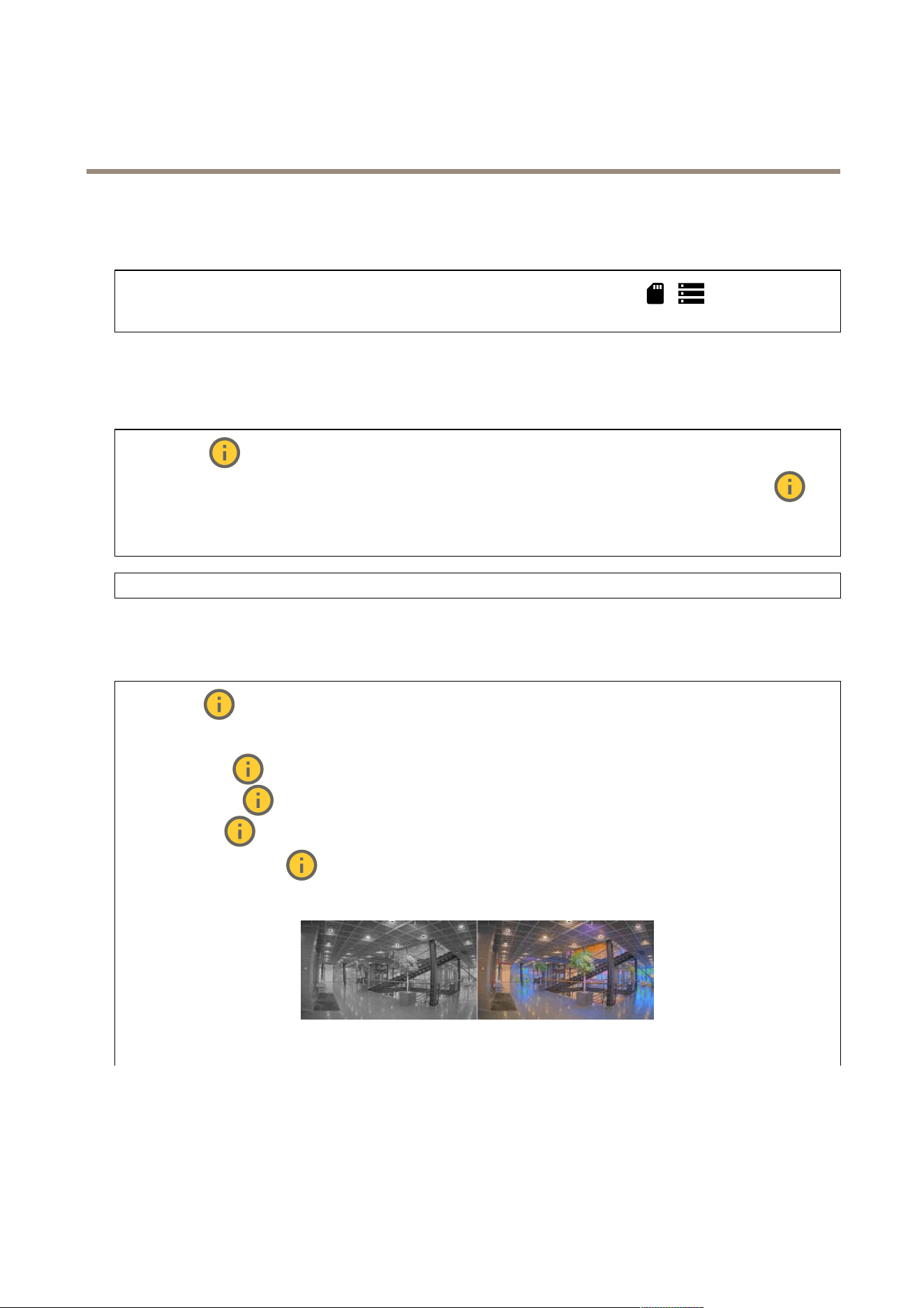
Wide dynamic range
WDR : T urn on to make both bright and dark areas of the image visible. Local contrast : Use the slider to adjust the
contrast of the image. A higher value makes the contrast higher between dark and light areas. T one mapping : Use the
slider to adjust the amount of tone mapping that is applied to the image. If the value is set to zero, only the standard gamma
correction is applied, while a higher value increases the visibility of the darkest and brightest parts in the image.
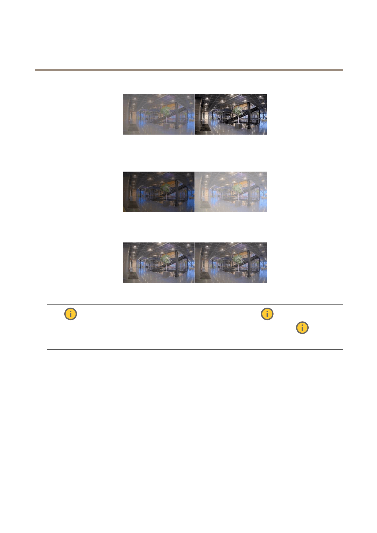
White balance
When the camera detects the color temperature of the incoming light, it can adjust the image to make the colors look more natural.
If this is not sufcient, you can select a suitable light source from the list.
The automatic white balance setting reduces the risk of color icker by adapting to changes gradually . If the lighting changes, or
when the camera is rst started, it can take up to 30 seconds to adapt to the new light source. If there is more than one type of light
source in a scene, that is, they differ in color temperature, the dominating light source acts as a reference for the automatic white
balance algorithm. This behavior can be overridden by choosing a xed white balance setting that matches the light source you
want to use as a reference.
13
AXIS I7020 Network Inter com
The web inter face
Light environment :
• Automatic : Automatic identication and compensation for the light source color . This is the recommended setting
which can be used in most situations.
• Automatic – outdoors : Automatic identication and compensation for the light source color . This is the
recommended setting which can be used in most outdoor situations.
• Custom – indoors : Fixed color adjustment for a room with some articial light other than uorescent lighting
and good for a normal color temperature around 2800 K.
• Custom – outdoors : Fixed color adjustment for sunny weather conditions with a color temperature around
5500 K.
• Fixed – uorescent 1 : Fixed color adjustment for uorescent lighting with a color temperature around 4000 K.
• Fixed – uorescent 2 : Fixed color adjustment for uorescent lighting with a color temperature around 3000 K.
• Fixed – indoors : Fixed color adjustment for a room with some articial light other than uorescent lighting and
good for a normal color temperature around 2800 K.
• Fixed – outdoors 1 : Fixed color adjustment for sunny weather conditions with a color temperature around 5500 K.
• Fixed – outdoors 2 : Fixed color adjustment for cloudy weather condition with a color temperature around 6500 K.
• Street light – mercury : Fixed color adjustment for ultraviolet emission in mercury vapor lights common
in street lighting.
• Street light – sodium : Fixed color adjustment that compensates for the yellow orange color of sodium vapor
lights common in street lighting.
• Hold current : K eep the current settings and do not compensate for light changes.
• Manual : Fix the white balance with the help of a white object. Drag the circle to an object that you want
the camera to interpret as white in the live view image. Use the Red balance and Blue balance sliders to adjust the
white balance manually .
Exposure
Select an exposure mode to reduce rapidly changing irregular effects in the image, for example, icker produced by different types of
light sources. W e recommend you to use the automatic exposure mode, or the same frequency as your power network.
Exposure mode :
• Automatic : The camera adjusts the aperture, gain, and shutter automatically .
• Automatic aperture : The camera adjusts the aperture and gain automatically . The shutter is xed.
• Automatic shutter : The camera adjusts the shutter and gain automatically . The aperture is xed.
• Hold current : Locks the current exposure settings.
• Flicker - free : The camera adjusts the aperture and gain automatically , and uses only the following shutter
speeds: 1/50 s ( 50 Hz) and 1/60 s ( 60 Hz).
• Flicker - free 50 Hz : The camera adjusts the aperture and gain automatically , and uses the shutter speed 1/50 s.
• Flicker - free 60 Hz : The camera adjusts the aperture and gain automatically , and uses the shutter speed 1/60 s.
• Flicker - reduced : This is the same as icker - free, but the camera might use shutter speeds faster than
1/1 00 s ( 50 Hz) and 1/120 s ( 60 Hz) for brighter scenes.
• Flicker - reduced 50 Hz : This is the same as icker - free, but the camera might use shutter speeds faster
than 1/1 00 s for brighter scenes.
• Flicker - reduced 60 Hz : This is the same as icker - free, but the camera might use shutter speeds faster
than 1/120 s for brighter scenes.
14
AXIS I7020 Network Inter com
The web inter face
• Manual : The aperture, gain, and shutter are xed.
Exposure zone : Use exposure zones to optimize the exposure in a selected part of the scene, for example, the area in
front of an entrance door .
Note
The exposure zones are related to the original image (unrotated), and the names of the zones apply to the original image.
This means, for example, that if the video stream is rotated 90°, then the Upper zone becomes the Right zone in the
stream, and Left becomes Lower .
• Automatic : Suitable for most situations.
• Center : Uses a xed area in the center of the image to calculate the exposure. The area has a xed size and
position in the live view .
• Full : Uses the entire live view to calculate the exposure.
• Upper : Uses an area with a xed size and position in the upper part of the image to calculate the exposure.
• Lower : Uses an area with a xed size and position in the lower part of the image to calculate the exposure.
• Left : Uses an area with a xed size and position in the left part of the image to calculate the exposure.
• Right : Uses an area with a xed size and position in the right part of the image to calculate the exposure.
• Spot : Uses an area with a xed size and position in the live view to calculate the exposure.
• Custom : Uses an area in the live view to calculate the exposure. Y ou can adjust the size and position of the area.
Max shutter : Select the shutter speed to provide the best image. Low shutter speeds (longer exposure) might cause motion blur
when there is movement, and a too high shutter speed might affect the image quality . Max shutter works with max gain to improve
the image. Max gain : Select the suitable max gain. If you increase the max gain, it improves the visible level of detail in dark
images, but also increases the noise level. More noise can also result in increased use of bandwidth and storage. If you set the max
gain to a high value, images can differ a lot if the light conditions are very different from day to night. Max gain works with max
shutter to improve the image. Motion - adaptive exposure : Select to reduce motion blur in low - light conditions. Blur - noise
trade - off : Use the slider to adjust the priority between motion blur and noise. If you want to prioritize low bandwidth and have
less noise at the expense of details in moving objects, move the slider towards Low noise . If you want to prioritize the preservation
of details in moving objects at the expense of noise and bandwidth, move the slider towards Low motion blur .
Note
Y ou can change the exposure either by adjusting the exposure time or by adjusting the gain. If you increase the exposure
time, it results in more motion blur , and if you increase the gain, it results in more noise. If you adjust the Blur - noise
trade - off towards Low noise , the automatic exposure will prioritize longer exposure times over increasing gain, and the
opposite if you adjust the trade - off towards Low motion blur . Both the gain and exposure time will eventually reach
their maximum values in low - light conditions, regardless of the priority set.
Lock aperture : T urn on to keep the aperture size set by the Aperture slider . T urn off to allow the camera to automatically
adjust the aperture size. Y ou can, for example, lock the aperture for scenes with permanent light conditions. Aperture : Use
the slider to adjust the aperture size, that is, how much light passes through the lens. T o allow more light to enter the sensor and
thereby produce a brighter image in low - light conditions, move the slider towards Open . An open aperture also reduces the depth
of eld, which means that objects close to or far from the camera can appear unfocused. T o allow more of the image to be in
focus, move the slider towards Closed . Exposure level : Use the slider to adjust the image exposure. Defog : T urn on to
detect the effects of foggy weather and automatically remove them for a clearer image.
Note
W e recommend you not to turn on Defog in scenes with low contrast, large light level variations, or when the autofocus is
slightly off. This can affect the image quality , for example, by increasing the contrast. Furthermore, too much light can
negatively impact the image quality when defog is active.
15

AXIS I7020 Network Inter com
The web inter face
Stream
General
Resolution : Select the image resolution suitable for the surveillance scene. A higher resolution increases bandwidth and
storage. Frame rate : T o avoid bandwidth problems on the network or reduce storage size, you can limit the frame rate to a xed
amount. If you leave the frame rate at zero, the frame rate is kept at the highest possible rate under the current conditions. A
higher frame rate requires more bandwidth and storage capacity . P - frames : A P - frame is a predicted image that shows only the
changes in the image from the previous frame. Enter the desired number of P - frames. The higher the number , the less bandwidth is
required. However , if there is network congestion, there could be a noticeable deterioration in the video quality . Compression : Use
the slider to adjust the image compression. High compression results in a lower bitrate and lower image quality . Low compression
improves the image quality , but uses more bandwidth and storage when you record. Signed video : T urn on to add the
signed video feature to the video. Signed video protects the video from tampering by adding cryptographic signatures to the video.
Zipstream
Zipstream is a bitrate reduction technology , optimized for video surveillance, that reduces the average bitrate in an H.264 or H.265
stream in real time. Axis Zipstream applies a high bitrate in scenes where there are multiple regions of interest, for example, in scenes
with moving objects. When the scene is more static, Zipstream applies a lower bitrate, and thereby reduces the required storage.
T o learn more, see Reducing the bit rate with Axis Zipstream
Select the bitrate reduction Strength :
• Off : No bitrate reduction.
• Low : No visible quality degradation in most scenes. This is the default option and it can be used in all types
of scenes to reduce the bitrate.
• Medium : Visible effects in some scenes through less noise and a slightly lower level of detail in regions of lower
interest, for example, where there’s no movement.
• High : Visible effects in some scenes through less noise and a lower level of detail in regions of lower interest, for
example, where there’s no movement. W e recommend this level for cloud - connected devices and devices that
use local storage.
• Higher : Visible effects in some scenes through less noise and a lower level of detail in regions of lower interest,
for example, where there’s no movement.
• Extreme : Visible effects in most scenes. The bitrate is optimized for smallest possible storage.
Optimize for storage : T urn on to minimize the bitrate while maintaining quality . The optimization does not apply to the stream
shown in the web client. This can only be used if your VMS supports B - frames. T urning on Optimize for storage also turns on
Dynamic GOP . Dynamic FPS (frames per second): T urn on to allow the bandwidth to vary based on the level of activity in the
scene. More activity requires more bandwidth. Lower limit : Enter a value to adjust the frame rate between minimal fps and the
stream default fps based on scene motion. W e recommend you to use lower limit in scenes with very little motion, where the fps
could drop to 1 or lower . Dynamic GOP (Group of Pictures): T urn on to dynamically adjust the interval between I - frames based on
the level of activity in the scene. Upper limit : Enter a maximum GOP length, that is, the maximum number of P - frames between
two I - frames. An I - frame is a self - contained image frame that is independent of other frames.
Bitrate control
• Average : Select to automatically adjust the bitrate over a longer time period and provide the best possible image
quality based on the available storage.
- Click to calculate the target bitrate based on available storage, retention time, and bitrate limit.
- T arget bitrate : Enter desired target bitrate.
- Retention time : Enter the number of days to keep the recordings.
- Storage : Shows the estimated storage that can be used for the stream.
- Maximum bitrate : T urn on to set a bitrate limit.
- Bitrate limit : Enter a bitrate limit that is higher than the target bitrate.
• Maximum : Select to set a maximum instant bitrate of the stream based on your network bandwidth.
- Maximum : Enter the maximum bitrate.
• V ariable : Select to allow the bitrate to vary based on the level of activity in the scene. More activity requires more
bandwidth. W e recommend this option for most situations.
16
AXIS I7020 Network Inter com
The web inter face
Orientation
Mirror : T urn on to mirror the image.
Audio
Include : T urn on to use audio in the video stream. Source : Select what audio source to use. Stereo : T urn on to
include built - in audio as well as audio from an external microphone.
Overlays
: Click to add an overlay . Select the type of overlay from the dropdown list:
• T ext : Select to show a text that is integrated in the live view image and visible in all views, recordings and snapshots.
Y ou can enter your own text, and you can also include pre - congured modiers to automatically show , for example,
time, date, and frame rate.
- : Click to add the date modier %F to show yyyy - mm - dd.
- : Click to add the time modier %X to show hh:mm:ss (24 - hour clock).
- Modiers : Click to select any of the modiers shown in the list to add them to the text box. For example,
%a shows the day of the week.
- Size : Select the desired font size.
- Appearance : Select the text color and background color , for example, white text on a black background
(default).
- : Select the position of the overlay in the image.
• Image : Select to show a static image superimposed over the video stream. Y ou can use .bmp, .png, .jpeg, or .svg les.
T o upload an image, click Images . Before you upload an image, you can choose to:
- Scale with resolution : Select to automatically scale the overlay image to t the video resolution.
- Use transparency : Select and enter the RGB hexadecimal value for that color . Use the format RRGGBB .
Examples of hexadecimal values: FFFFFF for white, 000000 for black, FF0000 for red, 6633FF for blue, and
669900 for green. Only for .bmp images.
• Scene annotation : Select to show a text overlay in the video stream that stays in the same position, even
when the camera pans or tilts in another direction. Y ou can choose to only show the overlay within certain zoom levels.
- : Click to add the date modier %F to show yyyy - mm - dd.
- : Click to add the time modier %X to show hh:mm:ss (24 - hour clock).
- Modiers : Click to select any of the modiers shown in the list to add them to the text box. For example,
%a shows the day of the week.
- Size : Select the desired font size.
- Appearance : Select the text color and background color , for example, white text on a black background
(default).
- : Select the position of the overlay in the image. The overlay is saved and remains in the pan and
tilt coordinates of this position.
- Annotation between zoom levels (%) : Set the zoom levels which the overlay will be shown within.
- Annotation symbol : Select a symbol that appears instead of the overlay when the camera is not within the
set zoom levels.
• Streaming indicator : Select to show an animation superimposed over the video stream. The animation
indicates that the video stream is live, even if the scene doesn’t contain any motion.
- Appearance : Select the animation color and background color , for example, red animation on a transparent
background (default).
- Size : Select the desired font size.
17
AXIS I7020 Network Inter com
The web inter face
- : Select the position of the overlay in the image.
• Widget: Linegraph : Show a graph chart that displays how a measured value changes over time.
- Title : Enter a title for the widget.
- Overlay modier : Select an overlay modier as data source. If you have created MQTT overlays, they will be
located at the end of the list.
- : Select the position of the overlay in the image.
- Size : Select the size of the overlay .
- Visible on all channels : T urn off to show only on your currently selected channel. T urn on to show on all
active channels.
- Update interval : Choose the time between data updates.
- T ransparency : Set the transparency of the entire overlay .
- Background transparency : Set the transparency only of the background of the overlay .
- P oints : T urn on to add a point to the graph line when data is updated.
- X axis
- Label : Enter the text label for the x axis.
- Time window : Enter how long time the data is visualized.
- Time unit : Enter a time unit for the x axis.
- Y axis
- Label : Enter the text label for the y axis.
- Dynamic scale : T urn on for the scale to automatically adapt to the data values. T urn off to manually enter
values for a xed scale.
- Min alarm threshold and Max alarm threshold : These values will add horizontal reference lines to the graph,
making it easier to see when the data value becomes too high or too low .
• Widget: Meter : Show a bar chart that displays the most recently measured data value.
- Title : Enter a title for the widget.
- Overlay modier : Select an overlay modier as data source. If you have created MQTT overlays, they will be
located at the end of the list.
- : Select the position of the overlay in the image.
- Size : Select the size of the overlay .
- Visible on all channels : T urn off to show only on your currently selected channel. T urn on to show on all
active channels.
- Update interval : Choose the time between data updates.
- T ransparency : Set the transparency of the entire overlay .
- Background transparency : Set the transparency only of the background of the overlay .
- P oints : T urn on to add a point to the graph line when data is updated.
- Y axis
- Label : Enter the text label for the y axis.
- Dynamic scale : T urn on for the scale to automatically adapt to the data values. T urn off to manually enter
values for a xed scale.
- Min alarm threshold and Max alarm threshold : These values will add horizontal reference lines to the bar
chart, making it easier to see when the data value becomes too high or too low .
Privacy masks
: Click to create a new privacy mask. Privacy masks : Click to change the color of all privacy masks, or to delete all privacy
masks permanently . Mask x : Click to rename, disable, or permanently delete the mask.
18

AXIS I7020 Network Inter com
The web inter face
Communication
Contact list
Contacts
Click to download the contact list as a json le. Click to import a contact list (json). Add contact : Click to add a
new contact to the contact list. First name : Enter the contact’s rst name. Last name : Enter the contact’s last name. Speed dial
: Enter an available speed dial number for the contact. This number is used to call the contact from the device. SIP address :
If you use SIP , enter the contact's IP address or extension. : Click to make a test call. The call will automatically end when
answered. SIP account : If you use SIP , select the SIP account to use for the call from the device to the contact. Availability : Select
the contact’s availability schedule. If a call is attempted when the contact isn’t available, the call is canceled unless there’s a
fallback contact. Fallback : If applicable, select a fallback contact from the list. The context menu contains: Edit contact : Edit
the contact’s properties. Delete contact : Delete the contact.
SIP
Settings
Session Initiation Protocol (SIP) is used for interactive communication sessions between users. The sessions can include audio
and video.
SIP setup assistant : Click to set up and congure SIP step by step. Enable SIP : Check this option to make it possible to initiate and
receive SIP calls. Allow incoming calls : Check this option to allow incoming calls from other SIP devices.
Call handling
• Calling timeout : Set the maximum duration of an attempted call if no one answers.
• Incoming call duration : Set the maximum time an incoming call can last (max 1 0 min).
• End calls after : Set the maximum time that a call can last (max 60 minutes). Select Innite call duration if you don’t
want to limit the length of a call.
P orts
A port number must be between 1 0 24 and 65535.
• SIP port : The network port used for SIP communication. The signaling trafc through this port is non - encrypted.
The default port number is 5060. Enter a different port number if required.
• TLS port : The network port used for encrypted SIP communication. The signaling trafc through this port is encrypted
with T ransport Layer Security (TLS). The default port number is 506 1. Enter a different port number if required.
• RTP start port : The network port used for the rst RTP media stream in a SIP call. The default start port number is
4000. Some rewalls block RTP trafc on certain port numbers.
NA T traversal
Use NA T (Network Address T ranslation) traversal when the device is located on an private network (LAN) and you want to
make it available from outside of that network.
Note
For NA T traversal to work, the router must support it. The router must also support UPnP ® .
Each NA T traversal protocol can be used separately or in different combinations depending on the network environment.
• ICE : The ICE (Interactive Connectivity Establishment) protocol increases the chances of nding the most efcient
path to successful communication between peer devices. If you also enable STUN and TURN, you improve the ICE
protocol’s chances.
• STUN : STUN (Session T raversal Utilities for NA T) is a client - server network protocol that lets the device determine if
it is located behind a NA T or rewall, and if so obtain the mapped public IP address and port number allocated for
connections to remote hosts. Enter the STUN server address, for example, an IP address.
19

AXIS I7020 Network Inter com
The web inter face
• TURN : TURN (T raversal Using Relays around NA T) is a protocol that lets a device behind a NA T router or rewall receive
incoming data from other hosts over T CP or UDP . Enter the TURN server address and the login information.
Audio and video
• Audio codec priority : Select at least one audio codec with the desired audio quality for SIP calls. Drag - and - drop to
change the priority .
Note
The selected codecs must match the call recipient codec, since the recipient codec is decisive when a call is made.
• Audio direction : Select allowed audio directions.
• H.264 packetization mode : Select which packetization mode to use.
- Auto : (Recommended) The device decides which packetization mode to use.
- None : No packetization mode is set. This mode is often interpreted as mode 0 .
- 0 : Non - interleaved mode.
- 1 : Single NAL unit mode.
• Video direction : Select allowed video directions.
Additional
• UDP - to - T CP switching : Select to allow calls to switch transport protocols from UDP (User Datagram Protocol) to T CP
(T ransmission Control Protocol) temporarily . The reason for switching is to avoid fragmentation, and the switch can
take place if a request is within 200 bytes of the maximum transmission unit (MTU) or larger than 1300 bytes.
• Allow via rewrite : Select to send the local IP address instead of the router's public IP address.
• Allow contact rewrite : Select to send the local IP address instead of the router's public IP address.
• Register with server every : Set how often you want the device to register with the SIP server for the existing
SIP accounts.
• D TMF payload type : Changes the default payload type for D TMF .
• Max retransmissions : Set the maximum number of times the device tries to connect to the SIP server before it
stops trying.
• Seconds until failback : Set the number of seconds until the device tries to reconnect to the primary SIP server after it
has failed over to a secondary SIP server .
Accounts
All current SIP accounts are listed under SIP accounts . For registered accounts, the colored circle lets you know the status.
The account is successfully registered with the SIP server .
There is a problem with the account. P ossible reasons can be authorization failure, that the account credentials are wrong,
or that the SIP server can’t nd the account.
The peer to peer (default) account is an automatically created account. Y ou can delete it if you create at least one other account
and set that account as default. The default account is always used when a VAPIX ® Application Programming Interface (API) call
is made without specifying which SIP account to call from.
Add account : Click to create a new SIP account.
• Active : Select to be able to use the account.
• Make default : Select to make this the default account. There must be a default account, and there can only
be one default account.
• Answer automatically : Select to automatically answer an incoming call.
• Prioritize IPv6 over IPv4 : Select to prioritize IPv6 addresses over IPv4 addresses. This is useful when you
connect to peer - to - peer accounts or domain names that resolve in both IPv4 and IPv6 addresses. Y ou can only
prioritize IPv6 for domain names that are mapped to IPv6 addresses.
• Name : Enter a descriptive name. This can, for example, be a rst and last name, a role, or a location. The name is
not unique.
• User ID : Enter the unique extension or phone number assigned to the device.
• P eer - to - peer : Use for direct calls to another SIP device on the local network.
• Registered : Use for calls to SIP devices outside the local network, through a SIP server .
20
AXIS I7020 Network Inter com
The web inter face
• Domain : If available, enter the public domain name. It will be shown as part of the SIP address when calling other
accounts.
• P assword : Enter the password associated with the SIP account for authenticating against the SIP server .
• Authentication ID : Enter the authentication ID used for authenticating against the SIP server . If it is the same as the
user ID, you don’t need to enter the authentication ID.
• Caller ID : The name which is presented to the recipient of calls from the device.
• Registrar : Enter the IP address for the registrar .
• T ransport mode : Select the SIP transport mode for the account: UPD, T CP , or TLS.
• TLS version (only with transport mode TLS): Select the version of TLS to use. V ersions v1.2 and v1.3 are the most
secure. Automatic selects the most secure version that the system can handle.
• Media encryption (only with transport mode TLS): Select the type of encryption for media (audio and video) in SIP calls.
• Certicate (only with transport mode TLS): Select a certicate.
• V erify server certicate (only with transport mode TLS): Check to verify the server certicate.
• Secondary SIP server : T urn on if you want the device to try to register on a secondary SIP server if registration
on the primary SIP server fails.
• SIP secure : Select to use Secure Session Initiation Protocol (SIPS). SIPS uses the TLS transport mode to encrypt trafc.
• Proxies
- Proxy : Click to add a proxy .
- Prioritize : If you have added two or more proxies, click to prioritize them.
- Server address : Enter the IP address of the SIP proxy server .
- Username : If required, enter the username for the SIP proxy server .
- P assword : If required, enter the password for the SIP proxy server .
• Video
- View area : Select the view area to use for video calls. If you select none, the native view is used.
- Resolution : Select the resolution to use for video calls. The resolution affects the required bandwidth.
- Frame rate : Select the number of frames per second for video calls. The frame rate affects the required
bandwidth.
- H.264 prole : Select the prole to use for video calls.
D TMF
Add sequence : Click to create a new dual - tone multifrequency (D TMF) sequence. T o create a rule that is activated by
touch - tone, go to Events > Rules . Sequence : Enter the characters to activate the rule. Allowed characters: 0–9, A - D, #, and
*. Description : Enter a description of the action to be triggered by the sequence. Accounts : Select the accounts that will use the
D TMF sequence. If you choose peer - to - peer , all peer - to - peer accounts will share the same D TMF sequence.
Protocols Select the protocols to use for each account. All peer - to - peer accounts share the same protocol settings. Use RTP
(RFC2833) : T urn on to allow dual - tone multifrequency (D TMF) signaling, other tone signals and telephony events in RTP
packets. Use SIP INFO (RFC2976) : T urn to include the INFO method to the SIP protocol. The INFO method adds optional
application layer information, generally related to the session.
T est call
SIP account : Select which account to make the test call from. SIP address : Enter a SIP address and click to make a test call
and verify that the account works.
Access list
Use access list : T urn on to restrict who can make calls to the device.
P olicy :
• Allow : Select to allow incoming calls only from the sources in the access list.
• Block : Select to block incoming calls from the sources in the access list.
Add source : Click to create a new entry in the access list. SIP source : T ype the caller ID or SIP server address of the source.
2 1
AXIS I7020 Network Inter com
The web inter face
Multicast controller
User multicast controller : T urn on to activate multicast controller . Audio codec : Select an audio codec. Source : Add
a new multicast controller source.
• Label : Enter the name of a label that is not already used by a source.
• Source : Enter a source.
• P ort : Enter a port.
• Priority : Select a priority .
• Prole : Select a prole.
• SRTP key : Enter an SRTP key .
The context menu contains: Edit : Edit the multicast controller source. Delete : Delete the multicast controller source.
Calls
Call button
Enable call button : T urn on to make it possible to use the call button. Standby light : Select an option for the built - in light
around the call button.
• Auto : The device turns the built - in light on and off based on the surrounding light.
• On : The built - in light is always turned on when the device is in standby mode.
• Off : The built - in light is always turned off when the device is in standby mode.
Recipients : Select or create one or more contacts to call when someone presses the call button. If you add more than one recipient,
the call will be placed to all of them at the same time. The maximum number of SIP call recipients is six, while you can have an
unlimited number of VMS call recipients. Fallback : Add a fallback contact from the list in case none of the recipients replies.
General
Audio
Note
• The selected audio clip is only played when a call is made.
• If you change the audio clip or gain during an ongoing call, it doesn’t take effect until the next call.
Ringtone : Select the audio clip to play when someone makes a call to the device. Use the slider to adjust the gain. Ringback tone :
Select the audio clip to play when someone makes a call from the device. Use the slider to adjust the gain.
VMS calls
VMS calls
Allow calls in the video management software (VMS) : Select to allow calls from the device to the VMS. Y ou can make VMS calls
even if SIP is turned off. Call timeout : Set the maximum duration of an attempted call if no one answers.
22

AXIS I7020 Network Inter com
The web inter face
Reader
Connection
External reader (Input)
Use external OSDP reader : T urn on to use the device with an external reader . Connect the reader to the reader connector .
Status :
• Connected : The device is connected to the active external reader .
• Connecting : The device is trying to connect to the external reader .
• Not connected : OSDP is turned off.
Reader protocol
Reader protocol type : Select the protocol to use for the reader functionality .
• VAPIX reader : Can only be used with an Axis door controller .
- Protocol : Select HTTPS or HTTP .
- Door controller address : Enter the IP address for the door controller .
- User name : Enter the username of the door controller .
- P assword : Enter the password of the door controller .
- Connect : Click to connect to the door controller .
- Select reader : Select the entrance reader for the appropriate door .
• OSDP :
- OSDP address : Enter the OSDP reader address. 0 is the default and most common address for single readers.
• Wiegand :
- Beeper : T urn on to activate the beeper input.
- Input for beeper : Select the I/O port used for the beeper .
- Input used for LED control : Select how many I/O ports to use for controlling LED feedback on the device.
- Input for LED1/LED2 : Select which I/O ports to use for LED input.
- Idle color : If no I/O port is used to control the LED, you can select a static color to show on the card reader
indicator stripe.
- Color for state low/high : If one I/O port is used for LED control, select the color to show for state low and
state high respectively .
- Idle color/LED1 color/LED2 color/LED1 + LED2 color : If two I/O ports are used for LED control, select the
colors to show for idle, LED1, LED2, and LED1 + LED2 respectively .
- K eypress format : Select how to format the PIN when it’s sent to the access control unit.
- FourBit : PIN 1234 is encoded and sent as 0x1 0x2 0x3 0x4. This is the default and most common behaviour .
- EightBitZeroP added : PIN 1234 is encoded and sent as 0x0 1 0x0 2 0x03 0x04.
- EightBitInvertP added : PIN 1234 is encoded and sent as 0xE1 0xD2 0xC3 0xB4.
- Wiegand26 : The PIN is encoded in Wiegand26 format with an 8 bit facility code and a 16 bit id.
- Wiegand34 : The PIN is encoded in a Wiegand34 format with a 16 bit facility code and a 16 bit id.
- Wiegand37 : The PIN is encoded in a Wiegand37 format (H1 030 2) with a 35 bit id.
- Wiegand37FacilityCode : The PIN is encoded in a Wiegand37 format (H1 0304) with a 16 bit facility code and
a 19 bit id.
- Facility code : Enter the facility code to be sent. This option is only available for some keypress formats.
23

AXIS I7020 Network Inter com
The web inter face
Output format
Select data format : Select in which format to send card data to the access control unit.
• Raw : T ransmits the card data as it is.
• Wiegand26 : Encodes the card data in Wiegand26 format with an 8 bit facility code and a 16 bit id.
• Wiegand34 : Encodes the card data in Wiegand34 format with a 16 bit facility code and a 16 bit id.
• Wiegand37 : Encodes the card data in Wiegand37 format (H1 030 2) with a 35 bit id.
• Wiegand37FacilityCode : Encodes the card data in Wiegand37 format (H1 0304) with a 16 bit facility code and
a 19 bit id.
• Custom : Dene your own formatting.
Facility code override mode : Select an option for overriding the facility code.
• Auto : Doesn’t override the facility code, and creates a facility code from the input data auto detection. Either uses the
card’s original facility code, or forges it from excess bits of a card number .
• Optional : Uses the facility code from the input data, or overrides with a congured optional value.
• Override : Always overrides with a specied facility code.
PIN
The PIN settings must match the ones congured in the access control unit.
Length (0–32) : Enter the number of digits in the PIN. If users aren’t required to use a PIN when they use the reader , set the
length to 0. Timeout (seconds , 3–50) : Enter the number of seconds that need to pass before the device returns to idle mode
when no PIN is received.
Entry list
With Entry list, you can set up the device to allow credential holders to use their card or PIN to perform different actions, such as
opening a door . Y ou store the credentials locally in the device. Y ou can also combine this functionality with an external door controller .
Use Entry list : T urn on to use the Entry list functionality . Use connected door controller : T urn on if the device is already connected
to a door controller . If someone presents a credential that doesn’t exist in Entry list, we’ll send the request to the connected
door controller . W e don’t send credentials that are available in Entry list. Add credential holder : Click to add a new credential
holder . First name : Enter a rst name. Last name : Enter a last name. Credential type :
• PIN :
- PIN : Enter a unique PIN or click Generate to create one automatically .
• Card :
- UID : Enter the card’s UID and bit length, or click Get latest to fetch the data from the latest card swipe.
Event condition : Select one or more conditions to trigger when the credential holder uses their credential. T o set up the resulting
action, go to System > Events and create a rule, using the same condition you select here. V alid from : Select Current device time
to activate the credential immediately . Clear to specify when to activate the credential. V alid to :
• No end date : Credential is valid indenitely .
• End date : Specify the date and time when the credential becomes invalid.
• Number of times : Specify how many times the credential holder can use the credential. The value in the eld reduces
as the credential is used, to show the remaining uses.
Notes : Enter optional information. Suspend : Select to make the credential temporarily invalid.
Audio
Device settings
Input : T urn on or off audio input. Shows the type of input.
24
AXIS I7020 Network Inter com
The web inter face
Noise cancellation : T urn on to improve audio quality by removing background noise. Input type : Select the type of input,
for instance, if it’s internal microphone or line. P ower type : Select power type for your input. Apply changes : Apply
your selection. Echo cancellation : T urn on to remove echoes during two - way communication. Separate gain controls
: T urn on to adjust the gain separately for the different input types. Automatic gain control : T urn on to dynamically
adapt the gain to changes in the sound. Gain : Use the slider to change the gain. Click the microphone icon to mute or unmute.
Output : Shows the type of output.
Gain : Use the slider to change the gain. Click the speaker icon to mute or unmute.
Stream
Encoding : Select the encoding to use for the input source streaming. Y ou can only choose encoding if audio input is turned on. If
audio input is turned off, click Enable audio input to turn it on.
Audio clips
Add clip : Add a new audio clip. Y ou can use .au, .mp3, .opus, .vorbis, .wav les. Play the audio clip. Stop
playing the audio clip. The context menu contains:
• Rename : Change the name of the audio clip.
• Create link : Create a URL that, when used, plays the audio clip on the device. Specify the volume and number
of times to play the clip.
• Download : Download the audio clip to your computer .
• Delete : Delete the audio clip from the device.
Recordings
Ongoing recordings : Show all ongoing recordings on the device. Start a recording on the device. Choose which
storage device to save to. Stop a recording on the device. T riggered recordings will end when manually stopped or when the
device is shut down. Continuous recordings will continue until manually stopped. Even if the device is shut down, the recording
will continue when the device starts up again.
Play the recording. Stop playing the recording. Show or hide information and options about the
recording. Set export range : If you only want to export part of the recording, enter a time span. Note that if you work in a
different time zone than the location of the device, the time span is based on the device’s time zone. Encrypt : Select to set a
password for exported recordings. It will not be possible to open the exported le without the password. Click to delete a
recording. Export : Export the whole or a part of the recording.
Click to lter the recordings. From : Show recordings done after a certain point in time. T o : Show recordings up until a certain
point in time. Source : Show recordings based on source. The source refers to the sensor . Event : Show recordings based
on events. Storage : Show recordings based on storage type.
25

AXIS I7020 Network Inter com
The web inter face
Apps
Add app : Install a new app. Find more apps : Find more apps to install. Y ou will be taken to an overview page of Axis
apps. Allow unsigned apps : T urn on to allow installation of unsigned apps. Allow root - privileged apps : T urn on to
allow apps with root privileges full access to the device. View the security updates in AXIS OS and ACAP apps.
Note
The device’s performance might be affected if you run several apps at the same time.
Use the switch next to the app name to start or stop the app. Open : Access the app’s settings. The available settings depend on the
application. Some applications don’t have any settings. The context menu can contain one or more of the following options:
• Open - source license : View information about open - source licenses used in the app.
• App log : View a log of the app events. The log is helpful when you contact support.
• Activate license with a key : If the app requires a license, you need to activate it. Use this option if your device
doesn’t have internet access.
If you don’t have a license key , go to axis.com/products/analytics . Y ou need a license code and the Axis product serial
number to generate a license key .
• Activate license automatically : If the app requires a license, you need to activate it. Use this option if your device has
internet access. Y ou need a license code to activate the license.
• Deactivate the license : Deactivate the license to replace it with another license, for example, when you change from a
trial license to a full license. If you deactivate the license, you also remove it from the device.
• Settings : Congure the parameters.
• Delete : Delete the app permanently from the device. If you don’t deactivate the license rst, it remains active.
System
Time and location
Date and time
The time format depends on the web browser’s language settings.
Note
W e recommend you synchronize the device’s date and time with an NTP server .
Synchronization : Select an option for the device’s date and time synchronization.
• Automatic date and time (manual NTS KE servers) : Synchronize with the secure NTP key establishment servers
connected to the DHCP server .
- Manual NTS KE servers : Enter the IP address of one or two NTP servers. When you use two NTP servers,
the device synchronizes and adapts its time based on input from both.
- Max NTP poll time : Select the maximum amount of time the device should wait before it polls the NTP
server to get an updated time.
- Min NTP poll time : Select the minimum amount of time the device should wait before it polls the NTP
server to get an updated time.
• Automatic date and time (NTP servers using DHCP) : Synchronize with the NTP servers connected to the DHCP server .
- Fallback NTP servers : Enter the IP address of one or two fallback servers.
- Max NTP poll time : Select the maximum amount of time the device should wait before it polls the NTP
server to get an updated time.
- Min NTP poll time : Select the minimum amount of time the device should wait before it polls the NTP
server to get an updated time.
• Automatic date and time (manual NTP servers) : Synchronize with NTP servers of your choice.
- Manual NTP servers : Enter the IP address of one or two NTP servers. When you use two NTP servers, the
device synchronizes and adapts its time based on input from both.
26
AXIS I7020 Network Inter com
The web inter face
- Max NTP poll time : Select the maximum amount of time the device should wait before it polls the NTP
server to get an updated time.
- Min NTP poll time : Select the minimum amount of time the device should wait before it polls the NTP
server to get an updated time.
• Custom date and time : Manually set the date and time. Click Get from system to fetch the date and time settings
once from your computer or mobile device.
Time zone : Select which time zone to use. Time will automatically adjust to daylight saving time and standard time.
• DHCP : Adopts the time zone of the DHCP server . The device must connected to a DHCP server before you can select
this option.
• Manual : Select a time zone from the drop - down list.
Note
The system uses the date and time settings in all recordings, logs, and system settings.
Device location
Enter where the device is located. Y our video management system can use this information to place the device on a map.
• Latitude : P ositive values are north of the equator .
• Longitude : P ositive values are east of the prime meridian.
• Heading : Enter the compass direction that the device is facing. 0 is due north.
• Label : Enter a descriptive name for the device.
• Save : Click to save your device location.
Conguration check
Interactive device image : Click the buttons in the image to simulate real key presses. This allows you to try out congurations or
troubleshoot the hardware without having physical access to the device. Latest credentials : Shows information about the
credentials that were last registered. Show the latest credentials data. The context menu contains:
• Reverse UID : Invert the byte order of the UID.
• Revert UID : Revert the byte order of the UID back to the original order .
• Copy to clipboard : Copy the UID.
Check credentials : Enter a UID or a PIN and submit to check the credentials. The system will respond in the same way as
if you used the credentials at the device. If both UID and PIN is required, start by entering the UID.
Network
IPv4
Assign IPv4 automatically : Select to let the network router assign an IP address to the device automatically . W e recommend
automatic IP (DHCP) for most networks. IP address : Enter a unique IP address for the device. Static IP addresses can be assigned
at random within isolated networks, provided that each address is unique. T o avoid conicts, we recommend you contact your
network administrator before you assign a static IP address. Subnet mask : Enter the subnet mask to dene what addresses are
inside the local area network. Any address outside the local area network goes through the router . Router : Enter the IP address of
the default router (gateway) used to connect devices that are attached to different networks and network segments. Fallback to
static IP address if DHCP isn’t available : Select if you want to add a static IP address to use as fallback if DHCP is unavailable
and can’t assign an IP address automatically .
Note
If DHCP isn’t available and the device uses a static address fallback, the static address is congured with a limited scope.
IPv6
Assign IPv6 automatically : Select to turn on IPv6 and to let the network router assign an IP address to the device automatically .
Hostname
27

AXIS I7020 Network Inter com
The web inter face
Assign hostname automatically : Select to let the network router assign a hostname to the device automatically . Hostname :
Enter the hostname manually to use as an alternative way of accessing the device. The server report and system log use the
hostname. Allowed characters are A–Z, a–z, 0–9 and -.
DNS servers
Assign DNS automatically : Select to let the DHCP server assign search domains and DNS server addresses to the device
automatically . W e recommend automatic DNS (DHCP) for most networks. Search domains : When you use a hostname that is
not fully qualied, click Add search domain and enter a domain in which to search for the hostname the device uses. DNS
servers : Click Add DNS server and enter the IP address of the DNS server . This provides the translation of hostnames to IP
addresses on your network.
HTTP and HTTPS
HTTPS is a protocol that provides encryption for page requests from users and for the pages returned by the web server . The encrypted
exchange of information is governed by the use of an HTTPS certicate, which guarantees the authenticity of the server .
T o use HTTPS on the device, you must install an HTTPS certicate. Go to System > Security to create and install certicates.
Allow access through : Select if a user is allowed to connect to the device through the HTTP , HTTPS , or both HTTP and HTTPS
protocols.
Note
If you view encrypted web pages through HTTPS, you might experience a drop in performance, especially when you
request a page for the rst time.
HTTP port : Enter the HTTP port to use. The device allows port 80 or any port in the range 1 0 24 - 65535. If you are logged in as
an administrator , you can also enter any port in the range 1 - 1 0 23. If you use a port in this range, you get a warning. HTTPS
port : Enter the HTTPS port to use. The device allows port 443 or any port in the range 1 0 24 - 65535. If you are logged in as an
administrator , you can also enter any port in the range 1 - 1 0 23. If you use a port in this range, you get a warning. Certicate :
Select a certicate to enable HTTPS for the device.
Network discovery protocols
Bonjour
®
: T urn on to allow automatic discovery on the network. Bonjour name : Enter a friendly name to be visible on the network.
The default name is the device name and MAC address. UPnP
®
: T urn on to allow automatic discovery on the network. UPnP name :
Enter a friendly name to be visible on the network. The default name is the device name and MAC address. WS - Discovery : T urn on
to allow automatic discovery on the network. LLDP and CDP : T urn on to allow automatic discovery on the network. T urning LLDP
and CDP off can impact the P oE power negotiation. T o resolve any issues with the P oE power negotiation, congure the P oE
switch for hardware P oE power negotiation only .
One - click cloud connection
One - click cloud connection (O3C) together with an O3C service provides easy and secure internet access to live and recorded video
from any location. For more information, see axis.com/end - to - end - solutions/hosted - services .
Allow O3C :
• One - click : This is the default setting. Press and hold the control button on the device to connect to an O3C service
over the internet. Y ou need to register the device with the O3C service within 24 hours after you press the control
button. Otherwise, the device disconnects from the O3C service. Once you register the device, Always is enabled and
the device stays connected to the O3C service.
• Always : The device constantly attempts to connect to an O3C service over the internet. Once you register the device,
it stays connected to the O3C service. Use this option if the control button on the device is out of reach.
• No : Disables the O3C service.
Proxy settings : If needed, enter the proxy settings to connect to the proxy server . Host : Enter the proxy server’s address. P ort : Enter
the port number used for access. Login and P assword : If needed, enter username and password for the proxy server . Authentication
method :
• Basic : This method is the most compatible authentication scheme for HTTP . It’s less secure than the Digest method
because it sends the username and password unencrypted to the server .
• Digest : This method is more secure because it always transfers the password encrypted across the network.
28

AXIS I7020 Network Inter com
The web inter face
• Auto : This option lets the device select the authentication method depending on the supported methods. It prioritizes
the Digest method over the Basic method.
Owner authentication key (OAK) : Click Get key to fetch the owner authentication key . This is only possible if the device is
connected to the internet without a rewall or proxy .
SNMP
The Simple Network Management Protocol (SNMP) allows remote management of network devices.
SNMP : Select the version of SNMP to use.
• v1 and v2c :
- Read community : Enter the community name that has read - only access to all supported SNMP objects. The
default value is public .
- Write community : Enter the community name that has read or write access to all supported SNMP objects
(except read - only objects). The default value is write .
- Activate traps : T urn on to activate trap reporting. The device uses traps to send messages for important
events or status changes to a management system. In the web interface, you can set up traps for SNMP v1
and v2c. T raps are automatically turned off if you change to SNMP v3 or turn off SNMP . If you use SNMP v3,
you can set up traps through the SNMP v3 management application.
- T rap address : Enter the IP address or host name of the management server .
- T rap community : Enter the community to use when the device sends a trap message to the management
system.
- T raps :
- Cold start : Sends a trap message when the device starts.
- W arm start : Sends a trap message when you change an SNMP setting.
- Link up : Sends a trap message when a link changes from down to up.
- Authentication failed : Sends a trap message when an authentication attempt fails.
Note
All Axis Video MIB traps are enabled when you turn on SNMP v1 and v2c traps. For more information, see
AXIS OS P ortal > SNMP .
• v3 : SNMP v3 is a more secure version, which provides encryption and secure passwords. T o use SNMP v3, we
recommend you to activate HTTPS, as the password is then sent through HTTPS. This also prevents unauthorized
parties’ access to unencrypted SNMP v1 and v2c traps. If you use SNMP v3, you can set up traps through the SNMP v3
management application.
- P assword for the account “initial” : Enter the SNMP password for the account named “initial”. Although the
password can be sent without activating HTTPS, we don’t recommend it. The SNMP v3 password can only
be set once, and preferably only when HTTPS is enabled. Once the password is set, the password eld is no
longer displayed. T o set the password again, you must reset the device to factory default settings.
Security
Certicates
Certicates are used to authenticate devices on a network. The device supports two types of certicates:
• Client/server certicates
A client/server certicate validates the device’s identity , and can be self - signed or issued by a Certicate Authority (CA).
A self - signed certicate offers limited protection and can be used before a CA - issued certicate has been obtained.
• CA certicates
Y ou can use a CA certicate to authenticate a peer certicate, for example to validate the identity of an authentication
server when the device connects to a network protected by IEEE 80 2.1X. The device has several pre - installed CA
certicates.
These formats are supported:
• Certicate formats: .PEM, .CER, and .PFX
• Private key formats: PKCS#1 and PKCS#12
Important
If you reset the device to factory default, all certicates are deleted. Any pre - installed CA certicates are reinstalled.
29

AXIS I7020 Network Inter com
The web inter face
Add certicate : Click to add a certicate.
• More : Show more elds to ll in or select.
• Secure keystore : Select to use Secure element or T rusted Platform Module 2.0 to securely store the private key . For
more information on which secure keystore to select, go to help.axis.com/en - us/axis - os#cryptographic - support .
• K ey type : Select the default or a different encryption algorithm from the drop - down list to protect the certicate.
The context menu contains:
• Certicate information : View an installed certicate’s properties.
• Delete certicate : Delete the certicate.
• Create certicate signing request : Create a certicate signing request to send to a registration authority to apply
for a digital identity certicate.
Secure keystore :
• Secure element (CC EAL6+) : Select to use secure element for secure keystore.
• T rusted Platform Module 2.0 (CC EAL4+, FIPS 140 - 2 Level 2) : Select to use TPM 2.0 for secure keystore.
Network access control and encryption
IEEE 80 2.1x IEEE 80 2.1x is an IEEE standard for port - based network admission control providing secure authentication of wired
and wireless network devices. IEEE 80 2.1x is based on EAP (Extensible Authentication Protocol).T o access a network protected
by IEEE 80 2.1x, network devices must authenticate themselves. The authentication is performed by an authentication server ,
typically a RADIUS server (for example, FreeRADIUS and Microsoft Internet Authentication Server). IEEE 80 2.1AE MACsec IEEE
80 2.1AE MACsec is an IEEE standard for media access control (MAC) security that denes connectionless data condentiality
and integrity for media access independent protocols. Certicates When congured without a CA certicate, server certicate
validation is disabled and the device tries to authenticate itself regardless of what network it is connected to.When using a
certicate, in Axis' implementation, the device and the authentication server authenticate themselves with digital certicates
using EAP - TLS (Extensible Authentication Protocol - T ransport Layer Security).T o allow the device to access a network protected
through certicates, you must install a signed client certicate on the device. Authentication method : Select an EAP type used for
authentication. Client certicate : Select a client certicate to use IEEE 80 2.1x. The authentication server uses the certicate
to validate the client’s identity . CA certicates : Select CA certicates to validate the authentication server’s identity . When no
certicate is selected, the device tries to authenticate itself regardless of what network it is connected to. EAP identity : Enter the
user identity associated with the client certicate. EAPOL version : Select the EAPOL version that is used in the network switch. Use
IEEE 80 2.1x : Select to use the IEEE 80 2.1x protocol.These settings are only available if you use IEEE 80 2.1x PEAP - MSCHAPv2 as
the authentication method:
• P assword : Enter the password for your user identity .
• P eap version : Select the P eap version that is used in the network switch.
• Label : Select 1 to use client EAP encryption; select 2 to use client PEAP encryption. Select the Label that the network
switch uses when using P eap version 1.
These settings are only available if you use IEEE 80 2.1ae MACsec (Static CAK/Pre - Shared K ey) as the authentication method:
• K ey agreement connectivity association key name : Enter the connectivity association name (CKN). It must be 2 to 64
(divisible by 2) hexadecimal characters. The CKN must be manually congured in the connectivity association and
must match on both ends of the link to initially enable MACsec.
• K ey agreement connectivity association key : Enter the connectivity association key (CAK). It should be either 32
or 64 hexadecimal characters long. The CAK must be manually congured in the connectivity association and must
match on both ends of the link to initially enable MACsec.
Prevent brute - force attacks
Blocking : T urn on to block brute - force attacks. A brute - force attack uses trial - and - error to guess login info or encryption
keys. Blocking period : Enter the number of seconds to block a brute - force attack. Blocking conditions : Enter the number of
authentication failures allowed per second before the block starts. Y ou can set the number of failures allowed both on page
level and device level.
Firewall
30
AXIS I7020 Network Inter com
The web inter face
Activate : T urn on the rewall.
Default P olicy : Select the default state for the rewall.
• Allow: Allows all connections to the device. This option is set by default.
• Deny: Denies all connections to the device.
T o make exceptions to the default policy , you can create rules that allows or denies connections to the device from specic
addresses, protocols, and ports.
• Address : Enter an address in IPv4/IPv6 or CIDR format that you want to allow or deny access to.
• Protocol : Select a protocol that you want to allow or deny access to.
• P ort : Enter a port number that you want to allow or deny access to. Y ou can add a port number between 1 and 65535.
• P olicy : Select the policy of the rule.
: Click to create another rule.
Add rules: Click to add the rules that you have dened.
• Time in seconds: Set a time limit for testing the rules. The default time limit is set to 300 seconds. T o activate the
rules straight away , set the time to 0 seconds.
• Conrm rules: Conrm the rules and their time limit. If you have set a time limit of more than 1 second, the rules will
be active during this time. If you have set the time to 0 , the rules will be active straight away .
P ending rules : An overview of the latest tested rules that you are yet to conrm.
Note
The rules that have a time limit appear under Active rules until the displayed timer runs out, or until you conrm them. If
you don't conrm them, they will appear under P ending rules once the timer runs out, and the rewall will revert to the
previously dened settings. If you conrm them, they will replace the current active rules.
Conrm rules : Click to activate the pending rules. Active rules : An overview of the rules you are currently running on the device.
: Click to delete an active rule. : Click to delete all rules, both pending and active.
Custom signed AXIS OS certicate
T o install test software or other custom software from Axis on the device, you need a custom signed AXIS OS certicate. The
certicate veries that the software is approved by both the device owner and Axis. The software can only run on a specic device
which is identied by its unique serial number and chip ID. Only Axis can create custom signed AXIS OS certicates, since Axis
holds the key to sign them. Install : Click to install the certicate. Y ou need to install the certicate before you install the
software. The context menu contains:
• Delete certicate : Delete the certicate.
Accounts
Accounts
Add account : Click to add a new account. Y ou can add up to 1 00 accounts. Account : Enter a unique account name. New
password : Enter a password for the account. P asswords must be 1 to 64 characters long. Only ASCII printable characters (code
32 to 126) are allowed in the password, for example, letters, numbers, punctuation, and some symbols. Repeat password : Enter
the same password again. Privileges :
• Administrator : Has full access to all settings. Administrators can also add, update, and remove other accounts.
• Operator : Has access to all settings except:
- All System settings.
• Viewer : Has access to:
- W atch and take snapshots of a video stream.
- W atch and export recordings.
- P an, tilt, and zoom; with PTZ account access.
The context menu contains: Update account : Edit the account properties. Delete account : Delete the account. Y ou can’t
delete the root account.
3 1
AXIS I7020 Network Inter com
The web inter face
Anonymous access
Allow anonymous viewing : T urn on to allow anyone access the device as a viewer without logging in with an account. Allow
anonymous PTZ operating : T urn on to allow anonymous users to pan, tilt, and zoom the image.
SSH accounts
Add SSH account : Click to add a new SSH account.
• Restrict root access : T urn on to restrict functionality that requires root access.
• Enable SSH : T urn on to use SSH service.
Account : Enter a unique account name. New password : Enter a password for the account. P asswords must be 1 to 64 characters
long. Only ASCII printable characters (code 32 to 126) are allowed in the password, for example, letters, numbers, punctuation,
and some symbols. Repeat password : Enter the same password again. Comment : Enter a comment (optional). The context
menu contains: Update SSH account : Edit the account properties. Delete SSH account : Delete the account. Y ou can’t delete the
root account.
Virtual host
Add virtual host : Click to add a new virtual host. Enabled : Select to use this virtual host. Server name : Enter the name of
the server . Only use numbers 0 - 9, letters A - Z, and hyphen ( -). P ort : Enter the port the server is connected to. T ype : Select the type
of authentication to use. Select between Basic , Digest , and Open ID . The context menu contains:
• Update : Update the virtual host.
• Delete : Delete the virtual host.
Disabled : The server is disabled.
OpenID Conguration
Important
If you can't use OpenID to sign in, use the Digest or Basic credentials you used when you congured OpenID to sign in.
Client ID : Enter the OpenID username. Outgoing Proxy : Enter the proxy address for the OpenID connection to use a proxy
server . Admin claim : Enter a value for the admin role. Provider URL : Enter the web link for the API endpoint authentication. Format
should be https://[insert URL]/.well - known/openid - conguration Operator claim : Enter a value for the operator role. Require claim :
Enter the data that should be in the token. Viewer claim : Enter the value for the viewer role. Remote user : Enter a value to identify
remote users. This assists to display the current user in the device’s web interface. Scopes : Optional scopes that could be part of
the token. Client secret : Enter the OpenID password Save : Click to save the OpenID values. Enable OpenID : T urn on to close current
connection and allow device authentication from the provider URL.
Events
Rules
A rule denes the conditions that triggers the product to perform an action. The list shows all the currently congured rules in
the product.
Note
Y ou can create up to 256 action rules.
32
AXIS I7020 Network Inter com
The web inter face
Add a rule : Create a rule. Name : Enter a name for the rule. W ait between actions : Enter the minimum time (hh:mm:ss)
that must pass between rule activations. It is useful if the rule is activated by , for example, day - night mode conditions, to avoid
that small light changes during sunrise and sunset activate the rule repeatedly . Condition : Select a condition from the list. A
condition must be met for the device to perform an action. If multiple conditions are dened, all of them must be met to trigger
the action. For information about specic conditions, see Get started with rules for events . Use this condition as a trigger : Select
to make this rst condition function only as a starting trigger . It means that once the rule is activated, it remains active for as long
as all the other conditions are met, no matter the state of the rst condition. If you don’t select this option, the rule will simply be
active whenever all the conditions are met. Invert this condition : Select if you want the condition to be the opposite of your
selection. Add a condition : Click to add an additional condition. Action : Select an action from the list and enter its
required information. For information about specic actions, see Get started with rules for events .
Recipients
Y ou can set up your device to notify recipients about events or send les.
Note
If you set up your device to use FTP or SFTP , don’t change or remove the unique sequence number that’s added to the le
names. If you do that, only one image per event can be sent.
The list shows all the recipients currently congured in the product, along with information about their conguration.
Note
Y ou can create up to 20 recipients.
Add a recipient : Click to add a recipient. Name : Enter a name for the recipient. T ype : Select from the list:
• FTP
- Host : Enter the server's IP address or hostname. If you enter a hostname, make sure that a DNS server is
specied under System > Network > IPv4 and IPv6 .
- P ort : Enter the port number used by the FTP server . The default is 2 1.
- Folder : Enter the path to the directory where you want to store les. If this directory doesn’t already exist
on the FTP server , you will get an error message when uploading les.
- Username : Enter the username for the login.
- P assword : Enter the password for the login.
- Use temporary le name : Select to upload les with temporary , automatically generated lenames. The
les get renamed to the desired names when the upload completes. If the upload is aborted/interrupted,
you don’t get any corrupt les. However , you probably still get the temporary les. This way you know
that all les that have the desired name are correct.
- Use passive FTP : Under normal circumstances, the product simply requests the target FTP server to open the
data connection. The device actively initiates both the FTP control and data connections to the target server .
This is normally needed if there is a rewall between the device and the target FTP server .
• HTTP
- URL : Enter the network address to the HTTP server and the script that will handle the request. For example,
http://192.168.254.1 0/cgi - bin/notify .cgi.
- Username : Enter the username for the login.
- P assword : Enter the password for the login.
- Proxy : T urn on and enter the required information if a proxy server must be passed to connect to the HTTP
server .
• HTTPS
- URL : Enter the network address to the HTTPS server and the script that will handle the request. For example,
https://192.168.254.1 0/cgi - bin/notify .cgi.
- V alidate server certicate : Select to validate the certicate that was created by HTTPS server .
- Username : Enter the username for the login.
- P assword : Enter the password for the login.
33

AXIS I7020 Network Inter com
The web inter face
- Proxy : T urn on and enter the required information if a proxy server must be passed to connect to the HTTPS
server .
• Network storage
Y ou can add network storage such as NAS (network - attached storage) and use it as a recipient to store les. The les
are stored in the Matroska (MKV) le format.
- Host : Enter the IP address or hostname for the network storage.
- Share : Enter the name of the share on the host.
- Folder : Enter the path to the directory where you want to store les.
- Username : Enter the username for the login.
- P assword : Enter the password for the login.
• SFTP
- Host : Enter the server's IP address or hostname. If you enter a hostname, make sure that a DNS server is
specied under System > Network > IPv4 and IPv6 .
- P ort : Enter the port number used by the SFTP server . The default is 22.
- Folder : Enter the path to the directory where you want to store les. If this directory doesn’t already exist on
the SFTP server , you will get an error message when uploading les.
- Username : Enter the username for the login.
- P assword : Enter the password for the login.
- SSH host public key type (MD5) : Enter the ngerprint of the remote host’s public key (a 32 - digit
hexadecimal string). The SFTP client supports SFTP servers using SSH - 2 with RSA, DSA, ECDSA, and ED255 19
host key types. RSA is the preferred method during negotiation, followed by ECDSA, ED255 19, and DSA. Make
sure to enter the right MD5 host key that is used by your SFTP server . While the Axis device supports both
MD5 and SHA - 256 hash keys, we recommend using SHA - 256 due to stronger security over MD5. For more
information on how to congure an SFTP server with an Axis device, go to the AXIS OS P ortal .
- SSH host public key type (SHA256) : Enter the ngerprint of the remote host’s public key (a 43 - digit Base64
encoded string). The SFTP client supports SFTP servers using SSH - 2 with RSA, DSA, ECDSA, and ED255 19 host
key types. RSA is the preferred method during negotiation, followed by ECDSA, ED255 19, and DSA. Make
sure to enter the right MD5 host key that is used by your SFTP server . While the Axis device supports both
MD5 and SHA - 256 hash keys, we recommend using SHA - 256 due to stronger security over MD5. For more
information on how to congure an SFTP server with an Axis device, go to the AXIS OS P ortal .
- Use temporary le name : Select to upload les with temporary , automatically generated lenames. The
les get renamed to the desired names when the upload completes. If the upload is aborted or interrupted,
you don’t get any corrupt les. However , you probably still get the temporary les. This way , you know
that all les that have the desired name are correct.
• SIP or VMS :
SIP : Select to make a SIP call.
VMS : Select to make a VMS call.
- From SIP account : Select from the list.
- T o SIP address : Enter the SIP address.
- T est : Click to test that your call settings works.
• Email
- Send email to : Enter the email address to send emails to. T o enter multiple addresses, use commas to
separate them.
- Send email from : Enter the email address of the sending server .
- Username : Enter the username for the mail server . Leave this eld empty if the mail server does not
require authentication.
- P assword : Enter the password for the mail server . Leave this eld empty if the mail server does not require
authentication.
- Email server (SMTP) : Enter the name of the SMTP server , for example, smtp.gmail.com, smtp.mail.yahoo.com.
- P ort : Enter the port number for the SMTP server , using values in the range 0 - 65535. The default value is 587.
- Encryption : T o use encryption, select either SSL or TLS.
- V alidate server certicate : If you use encryption, select to validate the identity of the device. The certicate
can be self - signed or issued by a Certicate Authority (CA).
- POP authentication : T urn on to enter the name of the POP server , for example, pop.gmail.com.
Note
Some email providers have security lters that prevent users from receiving or viewing large amount of
attachments, from receiving scheduled emails and similar . Check the email provider's security policy to avoid
your email account being locked or missing out on your expected emails.
34

AXIS I7020 Network Inter com
The web inter face
• T CP
- Host : Enter the server's IP address or hostname. If you enter a hostname, make sure that a DNS server is
specied under System > Network > IPv4 and IPv6 .
- P ort : Enter the port number used to access the server .
T est : Click to test the setup. The context menu contains: View recipient : Click to view all the recipient details. Copy
recipient : Click to copy a recipient. When you copy , you can make changes to the new recipient. Delete recipient : Click to delete
the recipient permanently .
Schedules
Schedules and pulses can be used as conditions in rules. The list shows all the schedules and pulses currently congured in the
product, along with information about their conguration. Add schedule : Click to create a schedule or pulse.
Manual triggers
Y ou can use the manual trigger to manually trigger a rule. The manual trigger can, for example, be used to validate actions
during product installation and conguration.
MQTT
MQTT (Message Queuing T elemetry T ransport) is a standard messaging protocol for the Internet of Things (IoT). It was designed for
simplied IoT integration and is used in a wide variety of industries to connect remote devices with a small code footprint and
minimal network bandwidth. The MQTT client in Axis device software can simplify integration of data and events produced in the
device to systems which are not video management software (VMS).Set up the device as an MQTT client. MQTT communication is
based on two entities, the clients and the broker . The clients can send and receive messages. The broker is responsible for routing
messages between clients.Y ou can learn more about MQTT in AXIS OS P ortal .
ALPN
ALPN is a TLS/SSL extension that allows for the selection of an application protocol during the handshake phase of the connection
between the client and server . This is used to enable MQTT trafc over the same port that is used for other protocols, such as HTTP .
In some cases, there might not be a dedicated port open for MQTT communication. A solution in such cases is to use ALPN to
negotiate the use of MQTT as the application protocol on a standard port, allowed by the rewalls.
MQTT client
Connect : T urn on or off the MQTT client. Status : Shows the current status of the MQTT client. BrokerHost : Enter the hostname or
IP address of the MQTT server . Protocol : Select which protocol to use. P ort : Enter the port number .
• 1883 is the default value for MQTT over T CP
• 8883 is the default value for MQTT over SSL
• 80 is the default value for MQTT over W ebSocket
• 443 is the default value for MQTT over W ebSocket Secure
ALPN protocol : Enter the ALPN protocol name provided by your MQTT broker provider . This is only applicable with MQTT over SSL
and MQTT over W ebSocket Secure. Username : Enter the username that the client will use to access the server . P assword : Enter
a password for the username. Client ID : Enter a client ID. The client identier is sent to the server when the client connects to
it. Clean session : Controls the behavior at connection and disconnection time. When selected, the state information is discarded at
connect and disconnect. HTTP proxy : A URL with a maximum length of 255 bytes. Y ou can leave the eld empty if you don't want
to use an HTTP proxy . HTTPS proxy : A URL with a maximum length of 255 bytes. Y ou can leave the eld empty if you don't want to
use an HTTPS proxy . K eep alive interval : Enables the client to detect when the server is no longer available without having to wait
for the long T CP/IP timeout. Timeout : The time interval in seconds to allow a connect to complete. Default value: 60 Device topic
prex : Used in the default values for the topic in the connect message and L WT message on the MQTT client tab , and in the
publication conditions on the MQTT publication tab . Reconnect automatically : Species whether the client should reconnect
automatically after a disconnect. Connect message Species if a message should be sent out when a connection is established. Send
message : T urn on to send messages. Use default : T urn off to enter your own default message. T opic : Enter the topic for the default
35
AXIS I7020 Network Inter com
The web inter face
message. P ayload : Enter the content for the default message. Retain : Select to keep the state of client on this T opicQoS : Change
the QoS layer for the packet ow . Last Will and T estament message The Last Will T estament (L WT) lets a client provide a testament
along with its credentials when connecting to the broker . If the client disconnects ungracefully at some point later (maybe because
his power source died), it can let the broker deliver a message to other clients. This L WT message has the same form as an ordinary
message and gets routed via the same mechanics. Send message : T urn on to send messages. Use default : T urn off to enter your
own default message. T opic : Enter the topic for the default message. P ayload : Enter the content for the default message. Retain :
Select to keep the state of client on this T opicQoS : Change the QoS layer for the packet ow .
MQTT publication
Use default topic prex : Select to use the default topic prex, that is dened in the device topic prex in the MQTT client
tab . Include topic name : Select to include the topic that describes the condition in the MQTT topic. Include topic namespaces :
Select to include ONVIF topic namespaces in the MQTT topic. Include serial number : Select to include the device’s serial number in
the MQTT payload. Add condition : Click to add a condition. Retain : Denes which MQTT messages are sent as retained.
• None : Send all messages as non - retained.
• Property : Send only stateful messages as retained.
• All : Send both stateful and stateless messages as retained.
QoS : Select the desired level for the MQTT publication.
MQTT subscriptions
Add subscription : Click to add a new MQTT subscription. Subscription lter : Enter the MQTT topic that you want to
subscribe to. Use device topic prex : Add the subscription lter as prex to the MQTT topic. Subscription type :
• Stateless : Select to convert MQTT messages into a stateless message.
• Stateful : Select to convert MQTT messages into a condition. The payload is used as the state.
QoS : Select the desired level for the MQTT subscription.
MQTT overlays
Note
Connect to an MQTT broker before you add MQTT overlay modiers.
Add overlay modier : Click to add a new overlay modier . T opic lter : Add the MQTT topic that contains the data you want
to show in the overlay . Data eld : Specify the key for the message payload that you want to show in the overlay , assuming the
message is in JSON format.
Modier : Use the resulting modier when you create the overlay .
• Modiers that start with #XMP show all of the data received from the topic.
• Modiers that start with #XMD show the data specied in the data eld.
Storage
Network storage
36

AXIS I7020 Network Inter com
The web inter face
Ignore : T urn on to ignore network storage. Add network storage : Click to add a network share where you can save recordings.
• Address : Enter the IP address or host name of the host server , typically a NAS (network - attached storage). W e
recommend you to congure the host to use a xed IP address (not DHCP since a dynamic IP address can change) or
that you use DNS. Windows SMB/CIFS names are not supported.
• Network share : Enter the name of the shared location on the host server . Several Axis devices can use the same
network share since each device gets its own folder .
• User : If the server requires a login, enter the username. T o log in to a specic domain server , type
DOMAIN\username .
• P assword : If the server requires a login, enter the password.
• SMB version : Select the SMB storage protocol version to connect to the NAS. If you select Auto , the device tries
to negotiate one of the secure versions SMB: 3.0 2, 3.0, or 2.1. Select 1.0 or 2.0 to connect to older NAS that don’t
support higher versions. Y ou can read more about SMB support in Axis devices here .
• Add share without testing : Select to add the network share even if an error is discovered during the connection test.
The error can be, for example, that you didn’t enter a password even though the server requires one.
Remove network storage : Click to unmount, unbind, and remove the connection to the network share. This removes all settings
for the network share. Unbind : Click to unbind and disconnect the network share.
Bind : Click to bind and connect the network share. Unmount : Click to unmount the network share.
Mount : Click to mount the network share. Write protect : T urn on to stop writing to the network share and protect recordings from
being removed. Y ou can’t format a write - protected network share. Retention time : Select how long to keep recordings, to limit
the amount of old recordings, or to comply with regulations regarding data storage. If the network storage becomes full, old
recordings are removed before the selected time period passes. T ools
• T est connection : T est the connection to the network share.
• Format : Format the network share, for example, when you need to quickly erase all data. CIFS is the available
le system option.
Use tool : Click to activate the selected tool.
Onboard storage
Important
Risk of data loss and corrupted recordings. Do not remove the SD card while the device is running. Unmount the SD
card before you remove it.
Unmount : Click to safely remove the SD card. Write protect : T urn on to stop writing to the SD card and protect recordings from
being removed. Y ou can’t format a write - protected SD card. Autoformat : T urn on to automatically format a newly inserted SD
card. It formats the le system into ext4. Ignore : T urn on to stop storing recordings on the SD card. When you ignore the SD card,
the device no longer recognizes that the card exists. The setting is only available for administrators. Retention time : Select how
long to keep recordings, to limit the amount of old recordings, or to comply with regulations regarding data storage. If the SD card
becomes full, old recordings are removed before the selected time period has passed. T ools
• Check : Check for errors on the SD card. This only works for the ext4 le system.
• Repair : Repair errors in the ext4 le system. T o repair an SD card with the VFA T le system, eject the SD card, insert it
in a computer , and perform a disk repair .
• Format : Format the SD card, for example, when you need to change the le system or quickly erase all data. VFA T
and ext4 are the two available le system options. The recommended format is ext4, due to its resilience against
data loss if the card is ejected or if there is an abrupt power loss. However , you need a third - party ext4 driver or
application to access the le system from Windows®.
• Encrypt : Use this tool to format the SD card and enable encryption. Encrypt deletes all data stored on the SD card.
After using Encrypt , the data that’s stored on the SD card is protected using encryption.
• Decrypt : Use this tool to format the SD card without encryption. Decrypt deletes all data stored on the SD card. After
using Decrypt , the data that’s stored on the SD card is not protected using encryption.
• Change password : Change the password required to encrypt the SD card.
Use tool : Click to activate the selected tool.
W ear trigger : Set a value for the SD card wear level at which you want to trigger an action. The wear level ranges from 0–200%.
A new SD card that has never been used has a wear level of 0%. A wear level of 1 00% indicates that the SD card is close to
its expected lifetime. When the wear - level reaches 200%, there is a high risk of the SD card malfunctioning. W e recommend
setting the wear trigger between 80–90%. This gives you time to download any recordings as well as replace the SD card in
time before it potentially wears out. The wear trigger allows you to set up an event and get a notication when the wear
level reaches your set value.
37
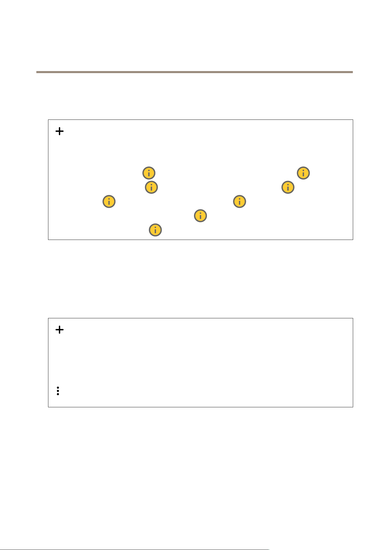
AXIS I7020 Network Inter com
The web inter face
Stream proles
A stream prole is a group of settings that affect the video stream. Y ou can use stream proles in different situations, for example,
when you create events and use rules to record.
Add stream prole : Click to create a new stream prole. Preview : A preview of the video stream with the stream
prole settings you select. The preview updates when you change the settings on the page. If your device has different
view areas, you can change the view area in the drop - down in the bottom left corner of the image. Name : Add a name for
your prole. Description : Add a description of your prole. Video codec : Select the video codec that should apply for the
prole. Resolution : See for a description of this setting. Frame rate : See for a description of this setting. Compression : See for
a description of this setting. Zipstream : See for a description of this setting. Optimize for storage : See for a
description of this setting. Dynamic FPS : See for a description of this setting. Dynamic GOP : See for a description
of this setting. Mirror : See for a description of this setting. GOP length : See for a description of this setting. Bitrate
control : See for a description of this setting. Include overlays : Select what type of overlays to include. See for information
about how to add overlays. Include audio : See for a description of this setting.
ONVIF
ONVIF accounts
ONVIF (Open Network Video Interface Forum) is a global interface standard that makes it easier for end - users, integrators,
consultants, and manufacturers to take advantage of the possibilities offered by network video technology . ONVIF enables
interoperability between different vendor products, increased exibility , reduced cost and future - proof systems.
When you create an ONVIF account, you automatically enable ONVIF communication. Use the account name and password for all
ONVIF communication with the device. For more information see the Axis Developer Community at axis.com .
Add accounts : Click to add a new ONVIF account. Account : Enter a unique account name. New password : Enter a password
for the account. P asswords must be 1 to 64 characters long. Only ASCII printable characters (code 32 to 126) are allowed in the
password, for example, letters, numbers, punctuation, and some symbols. Repeat password : Enter the same password again. Role :
• Administrator : Has full access to all settings. Administrators can also add, update, and remove other accounts.
• Operator : Has access to all settings except:
- All System settings.
- Adding apps.
• Media account : Allows access to the video stream only .
The context menu contains: Update account : Edit the account properties. Delete account : Delete the account. Y ou can’t
delete the root account.
ONVIF media proles
An ONVIF media prole consists of a set of congurations that you can use to change media stream settings. Y ou can create new
proles with your own set of congurations or use precongured proles for a quick setup.
38
AXIS I7020 Network Inter com
The web inter face
Add media prole : Click to add a new ONVIF media prole. Prole name : Add a name for the media prole. Video source :
Select the video source for your conguration.
• Select conguration : Select a user - dened conguration from the list. The congurations in the drop - down list
correspond to the device's video channels, including multiviews, view areas and virtual channels.
Video encoder : Select the video encoding format for your conguration.
• Select conguration : Select a user - dened conguration from the list and adjust the encoding settings. The
congurations in the drop - down list act as identiers/names of the video encoder conguration. Select user 0 to 15
to apply your own settings, or select one of the default users if you want to use predened settings for a specic
encoding format.
Note
Enable audio in the device to get the option to select an audio source and audio encoder conguration.
Audio source : Select the audio input source for your conguration.
• Select conguration : Select a user - dened conguration from the list and adjust the audio settings. The
congurations in the drop - down list correspond to the device's audio inputs. If the device has one audio input, it's
user0. If the device has several audio inputs, there will be additional users in the list.
Audio encoder : Select the audio encoding format for your conguration.
• Select conguration : Select a user - dened conguration from the list and adjust the audio encoding settings. The
congurations in the drop - down list act as identiers/names of the audio encoder conguration.
Audio decoder : Select the audio decoding format for your conguration.
• Select conguration : Select a user - dened conguration from the list and adjust the settings. The congurations in
the drop - down list act as identiers/names of the conguration.
Audio output : Select the audio output format for your conguration.
• Select conguration : Select a user - dened conguration from the list and adjust the settings. The congurations in
the drop - down list act as identiers/names of the conguration.
Metadata : Select the metadata to include in your conguration.
• Select conguration : Select a user - dened conguration from the list and adjust the metadata settings. The
congurations in the drop - down list act as identiers/names of the metadata conguration.
PTZ : Select the PTZ settings for your conguration.
• Select conguration : Select a user - dened conguration from the list and adjust the PTZ settings. The congurations
in the drop - down list correspond to the device's video channels with PTZ support.
Create : Click to save your settings and create the prole. Cancel : Click to cancel the conguration and clear all settings. prole_x :
Click on the prole name to open and edit the precongured prole.
Analytics metadata
Metadata producers
Lists the apps that stream metadata and the channels they use.
Producer : The app that produces the metadata. Below the app is a list of the types of metadata the app streams from the
device. Channel : The channel that the app uses. Select to enable the metadata stream. Deselect for compatibility or resource
management reasons.
Detectors
Camera tampering
The camera tampering detector generates an alarm when the scene changes, for example, when the lens is covered, sprayed
or severely put out of focus, and the time in T rigger delay has passed. The tampering detector only activates when the camera
has not moved for at least 1 0 seconds. During this period, the detector sets up a scene model to use as a comparison to detect
tampering in current images. For the scene model to be set up properly , make sure that the camera is in focus, the lighting
39
AXIS I7020 Network Inter com
The web inter face
conditions are correct, and the camera doesn’t point at a scene that lacks contours, for example, a blank wall. Camera tampering
can be used as a condition to trigger actions.
T rigger delay : Enter the minimum time that the tampering conditions must be active before the alarm triggers. This can help
prevent false alarms for known conditions that affect the image. T rigger on dark images : It is very difcult to generate alarms
when the camera lens is sprayed, since it is impossible to distinguish that event from other situations where the image turns dark
in a similar way , for example, when the lighting conditions change. T urn on this parameter to generate alarms for all cases where
the image turns dark. When it’s turned off, the device doesn’t generate any alarm when the image turns dark.
Note
For detection of tampering attempts in static and non - crowded scenes.
Audio detection
These settings are available for each audio input. Sound level : Adjust the sound level to a value from 0–1 00, where 0 is the most
sensitive and 1 00 the least sensitive. Use the activity indicator as a guide when you set the sound level. When you create events,
you can use the sound level as a condition. Y ou can choose to trigger an action if the sound level rises above, falls below or
passes the set value.
Shock detection
Shock detector : T urn on to generate an alarm if the device is hit by an object or if it is tampered with. Sensitivity level : Move
the slider to adjust the sensitivity level at which the device should generate an alarm. A low value means that the device only
generates an alarm if the hit is powerful. A high value means that the device generates an alarm even with mild tampering.
Accessories
I/O ports
Use digital input to connect external devices that can toggle between an open and closed circuit, for example, PIR sensors, door
or window contacts, and glass break detectors.
Use digital output to connect external devices such as relays and LEDs. Y ou can activate connected devices through the VAPIX®
Application Programming Interface or the web interface.
P ortName : Edit the text to rename the port. Usage : The default option for the relay port is Door . For devices with indicator icons,
turns green when the state changes and the door is unlocked. If you use the relay for something other than a door and
don’t want the icon to light up when the state changes, you can select one of the other options for the port. Direction :
indicates that the port is an input port. indicates that it’s an output port. If the port is congurable, you can click the icons
to change between input and output. Normal state : Click for open circuit, and for closed circuit. Current state : Shows
the current state of the port. The input or output is activated when the current state is different from the normal state. An input
on the device has an open circuit when it’s disconnected or when there is a voltage above 1 V DC.
Note
During restart, the output circuit is open. When the restart is complete, the circuit goes back to the normal position. If you
change any settings on this page, the output circuits go back to their normal positions regardless of any active triggers.
Supervised : T urn on to make it possible to detect and trigger actions if someone tampers with the connection to digital
I/O devices. In addition to detecting if an input is open or closed, you can also detect if someone has tampered with it (that is, cut
or shorted). T o supervise the connection requires additional hardware (end - of - line resistors) in the external I/O loop.
40

AXIS I7020 Network Inter com
The web inter face
Edge - to - edge
Camera pairing allows you to pair an Axis intercom with a compatible Axis camera, to include the camera’s live stream in SIP
and VMS calls.
Camera pairingAddress : Enter the host name or IP address of the camera. Username : Enter the username for the camera. P assword :
Enter the password for the camera. Disconnect : Click to disconnect the already connected camera. Connect : Click to connect
the camera.
Logs
Reports and logs
Reports
• View the device server report : View information about the product status in a pop - up window . The Access Log is
automatically included in the Server Report.
• Download the device server report : It creates a .zip le that contains a complete server report text le in UTF–8
format, as well as a snapshot of the current live view image. Always include the server report .zip le when you
contact support.
• Download the crash report : Download an archive with detailed information about the server's status. The crash report
contains information that is in the server report as well as detailed debug information. This report might contain
sensitive information such as network traces. It can take several minutes to generate the report.
Logs
• View the system log : Click to show information about system events such as device startup, warnings, and critical
messages.
• View the access log : Click to show all failed attempts to access the device, for example, when a wrong login
password is used.
Network trace
Important
A network trace le might contain sensitive information, for example certicates or passwords.
A network trace le can help you troubleshoot problems by recording activity on the network. T race time : Select the duration of
the trace in seconds or minutes, and click Download .
Remote system log
Syslog is a standard for message logging. It allows separation of the software that generates messages, the system that stores them,
and the software that reports and analyzes them. Each message is labeled with a facility code, which indicates the software
type generating the message, and assigned a severity level.
Server : Click to add a new server . Host : Enter the hostname or IP address of the server . Format : Select which syslog
message format to use.
• Axis
• RFC 3 164
• RFC 5424
Protocol : Select the protocol to use:
• UDP (Default port is 5 14)
• T CP (Default port is 60 1)
• TLS (Default port is 65 14)
P ort : Edit the port number to use a different port. Severity : Select which messages to send when triggered. CA certicate set :
See the current settings or add a certicate.
4 1

AXIS I7020 Network Inter com
The web inter face
Plain cong
Plain cong is for advanced users with experience of Axis device conguration. Most parameters can be set and edited from
this page.
Maintenance
Restart : Restart the device. This does not affect any of the current settings. Running applications restart automatically . Restore :
Return most settings to the factory default values. Afterwards you must recongure the device and apps, reinstall any apps that
didn’t come preinstalled, and recreate any events and presets.
Important
The only settings saved after restore are:
• Boot protocol (DHCP or static)
• Static IP address
• Default router
• Subnet mask
• 80 2.1X settings
• O3C settings
• DNS server IP address
Factory default : Return all settings to the factory default values. Afterwards you must reset the IP address to make the device
accessible.
Note
All Axis device software is digitally signed to ensure that you only install veried software on your device. This further
increases the overall minimum cybersecurity level of Axis devices. For more information, see the white paper “Axis
Edge V ault” at axis.com .
AXIS OS upgrade : Upgrade to a new AXIS OS version. New releases can contain improved functionality , bug xes, and completely
new features. W e recommend you to always use the latest AXIS OS release. T o download the latest release, go to axis.com/support .
When you upgrade, you can choose between three options:
• Standard upgrade : Upgrade to the new AXIS OS version.
• Factory default : Upgrade and return all settings to the factory default values. When you choose this option, you can’t
revert to the previous AXIS OS version after the upgrade.
• Autorollback : Upgrade and conrm the upgrade within the set time. If you don’t conrm, the device reverts to the
previous AXIS OS version.
AXIS OS rollback : Revert to the previously installed AXIS OS version.
42
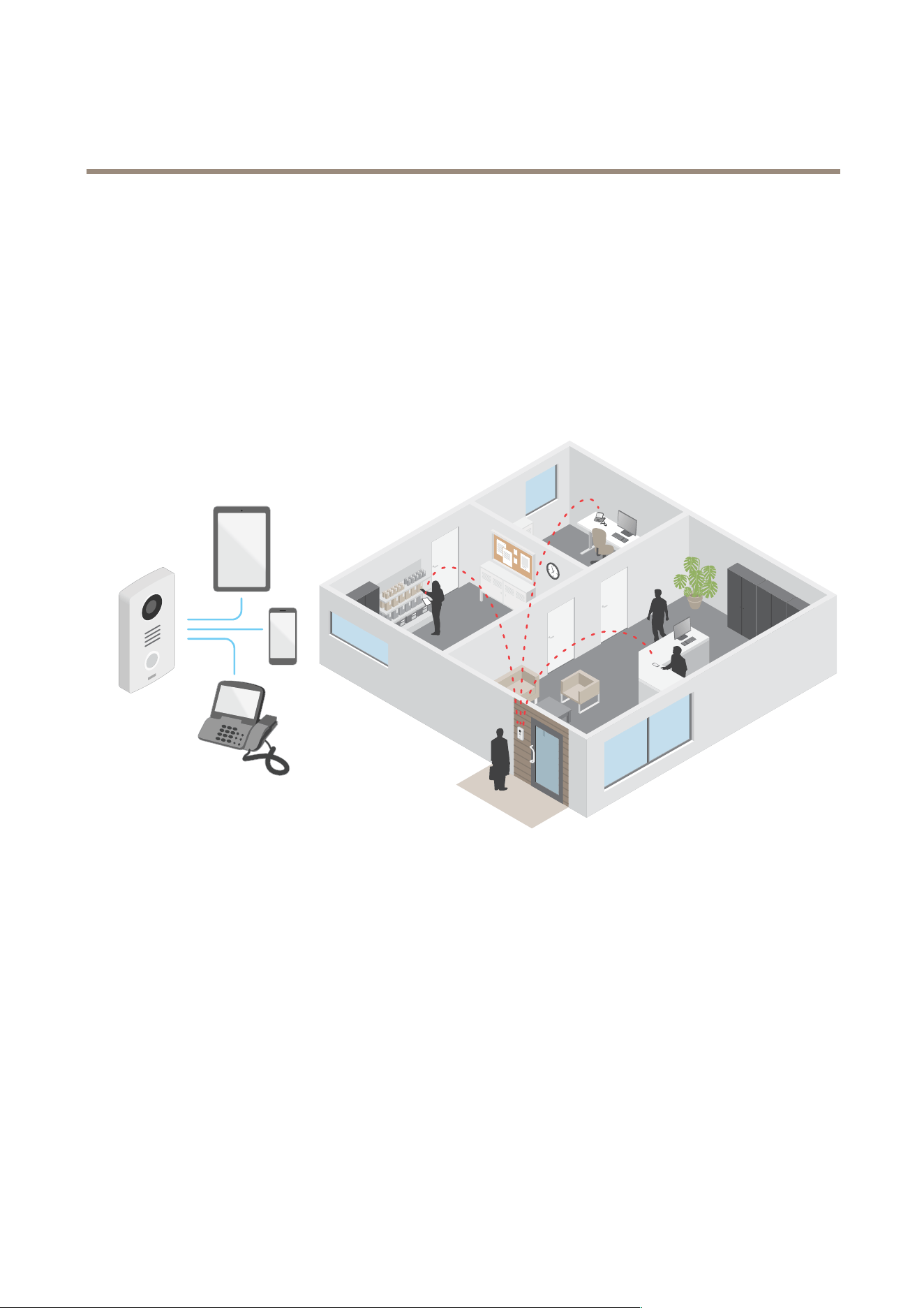
AXIS I7020 Network Inter com
Lear n mor e
Lear n mor e
V oice over IP (V oIP)
V oice over IP (V oIP) is a group of technologies that enables voice communication and multimedia sessions over IP networks, such as
the internet. In traditional phone calls, analog signals are sent through circuit transmissions over the Public Switched T elephone
Network (PSTN). In a V oIP call, analog signals are turned into digital signals to make it possible to send them in data packets
across local IP networks or the internet.
In the Axis product, V oIP is enabled through the Session Initiation Protocol (SIP) and Dual - T one Multi - Frequency (D TMF) signaling.
Example:
When you press the call button on an Axis intercom, a call is initiated to one or more predened recipients. When a recipient replies,
a call is established. The voice and video is transferred through V oIP technologies.
Session Initiation Protocol (SIP)
The Session Initiation Protocol (SIP) is used to set up, maintain and terminate V oIP calls. Y ou can make calls between two or more
parties, called SIP user agents. T o make a SIP call you can use, for example, SIP phones, softphones or SIP - enabled Axis devices.
The actual audio or video is exchanged between the SIP user agents with a transport protocol, for example RTP (Real - Time
T ransport Protocol).
Y ou can make calls on local networks using a peer - to - peer setup, or across networks using a PBX.
P eer - to - peer SIP (P2PSIP)
The most basic type of SIP communication takes place directly between two or more SIP user agents. This is called peer - to - peer SIP
(P2PSIP). If it takes place on a local network, all that’s needed are the SIP addresses of the user agents. A typical SIP address in this
case would be sip:<local - ip> .
Example:
43
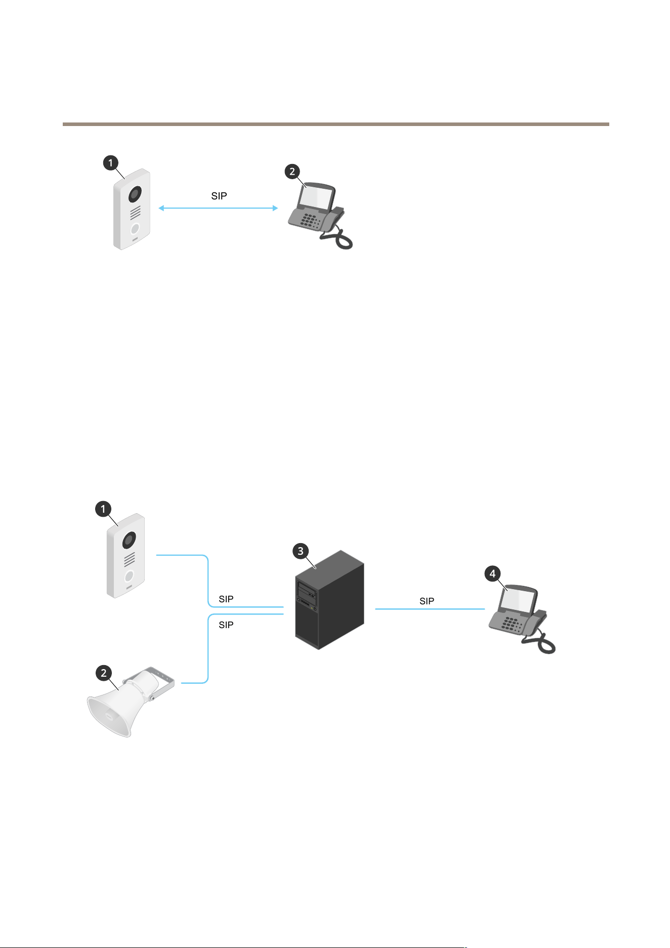
AXIS I7020 Network Inter com
Lear n mor e
SIP
1
User agent A - intercom. SIP address: sip:192.168.1.1 0 1
2
User agent B - SIP - enabled phone. SIP address: sip:192.168.1.1 00
Y ou can set up the Axis intercom to call for example a SIP - enabled phone on the same network using a peer - to - peer SIP setup.
Private Branch Exchange (PBX)
When you make SIP calls outside your local IP network, a Private Branch Exchange (PBX) can act as a central hub . The main
component of a PBX is a SIP server , which is also referred to as a SIP proxy or a registrar . A PBX works like a traditional switchboard,
showing the client's current status and allowing for example call transfers, voicemail, and redirections.
The PBX SIP server can be set up as a local entity or offsite. It can be hosted on an intranet or by a third party provider . When you
make SIP calls between networks, calls are routed through a set of PBXs, that query the location of the SIP address to be reached.
Each SIP user agent registers with the PBX, and can then reach the others by dialing the correct extension. A typical SIP address in
this case would be sip:<user>@<domain> or sip:<user>@<registrar - ip> . The SIP address is independent of its IP
address and the PBX makes the device accessible as long as it is registered to the PBX.
Example:
SIP
SIP
SIP
1
sip:mydoor@company .com
2
sip:myspeaker@company .com
3
PBX PBX
PBX
sip.company .com
4
sip:ofce@company .com
When you press the call button on an Axis intercom, the call is forwarded through one or more PBXs to a SIP address either on the
local IP network or over the internet.
44

AXIS I7020 Network Inter com
Lear n mor e
NA T traversal
Use NA T (Network Address T ranslation) traversal when the Axis device is located on an private network (LAN) and you want to
access it from outside of that network.
Note
The router must support NA T traversal and UPnP®.
Each NA T traversal protocol can be used separately or in different combinations depending on the network environment.
• ICE The ICE Interactive Connectivity Establishment) protocol increases the chances of nding the most efcient path to
successful communication between peer devices. If you also enable STUN and TURN, you improve the ICE protocol’s
chances.
• STUN - STUN (Session T raversal Utilities for NA T) is a client - server network protocol that lets the Axis device determine if
it is located behind a NA T or rewall, and if so obtain the mapped public IP address and port number allocated for
connections to remote hosts. Enter the STUN server address, for example, an IP address.
• TURN - TURN (T raversal Using Relays around NA T) is a protocol that lets a device behind a NA T router or rewall receive
incoming data from other hosts over T CP or UDP . Enter TURN server address and the login information.
Cybersecurity
For product - specic information about cybersecurity , see the product's datasheet at axis.com.
For in - depth information about cybersecurity in AXIS OS, read the AXIS OS Hardening guide .
Axis security notication service
Axis provides a notication service with information about vulnerability and other security related matters for Axis devices. T o receive
notications, you can subscribe at axis.com/security - notication - service .
Vulnerability management
T o minimize customers' risk of exposure, Axis, as a Common Vulnerability and Exposures (CVE) numbering authority (CNA) , follows
industry standards to manage and respond to discovered vulnerabilities in our devices, software, and services. For more information
about Axis vulnerability management policy , how to report vulnerabilities, already disclosed vulnerabilities, and corresponding
security advisories, see axis.com/vulnerability - management .
Secure operation of Axis devices
Axis devices with factory default settings are pre - congured with secure default protection mechanisms. W e recommend using more
security conguration when installing the device. T o nd out more about Axis hardening guides and other cyber security related
documentation, go to axis.com/support/cybersecurity/resources .
Applications
With applications, you can get more out of your Axis device. AXIS Camera Application Platform (ACAP) is an open platform that
makes it possible for third parties to develop analytics and other applications for Axis devices. Applications can be preinstalled on the
device, available for download for free, or for a license fee.
T o nd the user manuals for Axis applications, go to help.axis.com .
45
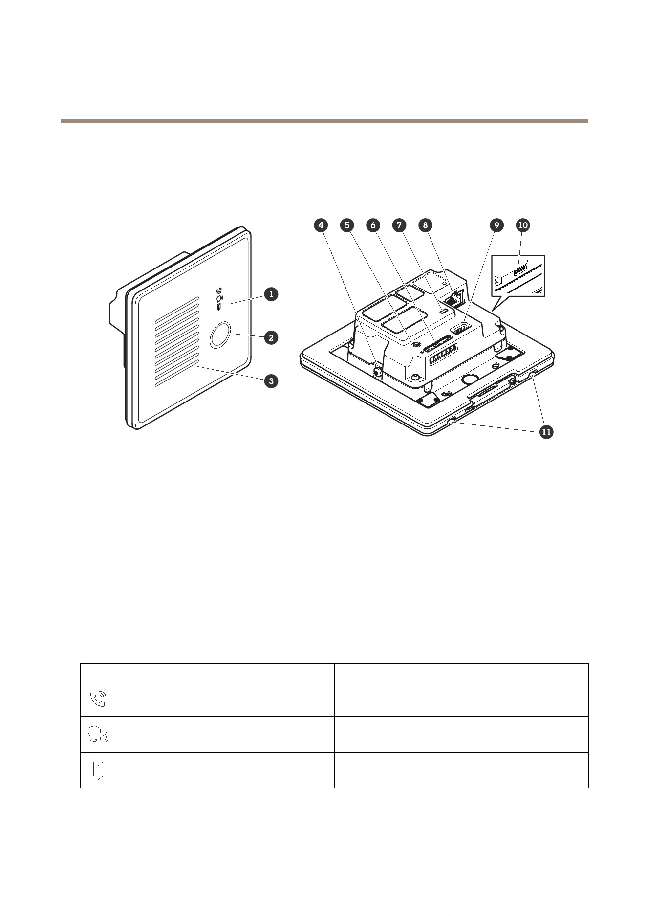
AXIS I7020 Network Inter com
Specifications
Specifications
Product overview
1
2
Call button
3
Speaker
4
Grounding screw
5
6
7
Status LED
8
9
1 0
(microSD/microSDHC/microSDXC)
1 1
Microphone (2x)
Front panel indicators and controls
When you connect the product to power , the front panel indicators light up for a few seconds.
Indicator icons
Icon Indication
Steady amber when outgoing call initiated.Flashes amber when
incoming call initiated.
Steady blue for ongoing call.
Steady green when door is open.
46

AXIS I7020 Network Inter com
Specifications
LED indicators
Status LED
Indication
Green Steady green for normal operation.
SD card slot
NO NO
NO
TICE TICE
TICE
• Risk of damage to SD card. Don’t use sharp tools, metal objects, or excessive force when inserting or removing the SD card.
Use your ngers to insert and remove the card.
• Risk of data loss and corrupted recordings. Unmount the SD card from the device’s web interface before removing it.
Don’t remove the SD card while the product is running.
This device supports microSD/microSDHC/microSDXC cards.
For SD card recommendations, see axis.com .
microSD, microSDHC, and microSDXC Logos are trademarks of SD - 3C LLC. microSD, microSDHC, microSDXC are
trademarks or registered trademarks of SD - 3C, LLC in the United States, other countries or both.
Buttons
Control button
The control button is used for:
• Resetting the product to factory default settings. See .
• Connecting to a one - click cloud connection (O3C) service over the internet. T o connect, press and hold the button
for about 3 seconds until the status LED ashes green.
Connectors
Network connector
RJ45 Ethernet connector with P ower over Ethernet (P oE).
Audio connector
4 - pin terminal block for audio input and output.
Function Pin Notes
Line in
1
Line in (mono)
GND
2
Audio ground
Line out
3
Line out (mono)
GND
4
Audio ground
47

AXIS I7020 Network Inter com
Specifications
I/O , reader , and relay connector
Y ou can use this connector for I/O and relay , or for reader connectivity .
6 - pin terminal block
1
-
2
12V
3
A/IO1
4
B/IO2
5
COM
6
NO/NC
Function Pin Notes
Specications
DC ground
1
0 V DC
DC output
2
Can be used to power auxiliary equipment.
Note: This pin can only be used as power out.
12 V DC
I/O : Max load = 50 mA
Reader/relay : Max load =
350 mA
I/O : Congurable
(Input or Output)
Reader : A
3
I/O : Digital input – Connect to pin 1 to activate, or leave oating
(unconnected) to deactivate. Digital output – Internally connected
to pin 1 (DC ground) when active, and oating (unconnected) when
inactive. If used with an inductive load, e.g., a relay , connect a diode
in parallel with the load, to protect against voltage transients.
Reader : RS485 – A
I/O : input – 0 to max 30 V DC
output – 0 to max 30 V DC,
open drain, 1 00 mA
I/O : Congurable
(Input or Output)
Reader : B
4
I/O : same as pin 3
Reader : RS485 – B
I/O : same as pin 3
Relay : COM
5
Common
Relay : NO/NC
6
Normally open/normally closed. For connecting relay devices. The
two relay pins are galvanically separated from the rest of the
circuitry .
Max current 7 00 mA, max
voltage 30 V DC
I/O connector
One option is to use the connector as an I/O connector with external devices in combination with, for example, motion detection,
event triggering, and alarm notications. In addition to the 0 V DC reference point and power (12 V DC output), the I/O connector
provides the interface to:
Digital input - For connecting devices that can toggle between an open and closed circuit, for example PIR sensors, door/window
contacts, and glass break detectors.
Digital output - For connecting external devices such as relays and LEDs. Connected devices can be activated by the VAPIX®
Application Programming Interface, through an event or from the device interface.
Example:
48
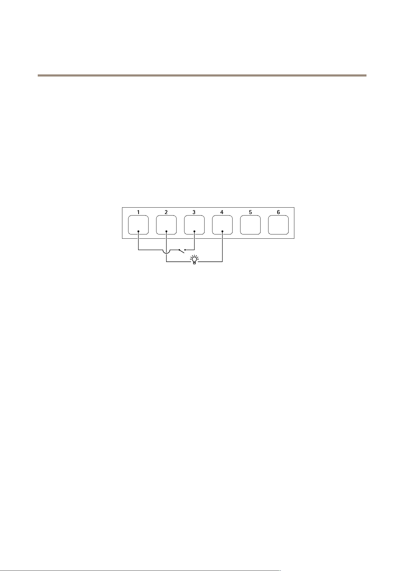
AXIS I7020 Network Inter com
Specifications
1
DC ground
2
DC output 12 V, max 50 mA
3
I/O congured as input
4
I/O congured as output
5
Relay only
6
Relay only
Relay connector
In combination with I/O , you can use the connector as a relay connector to connect a solid state relay , and use it:
• as a standard relay that opens and closes auxiliary circuits,
• to control a lock directly ,
• to control a lock through a safety relay . Using a safety relay on the secure side of the door prevents hotwiring.
Reader connector
A third option is to use the connector as a reader connector to connect an external reader .
49
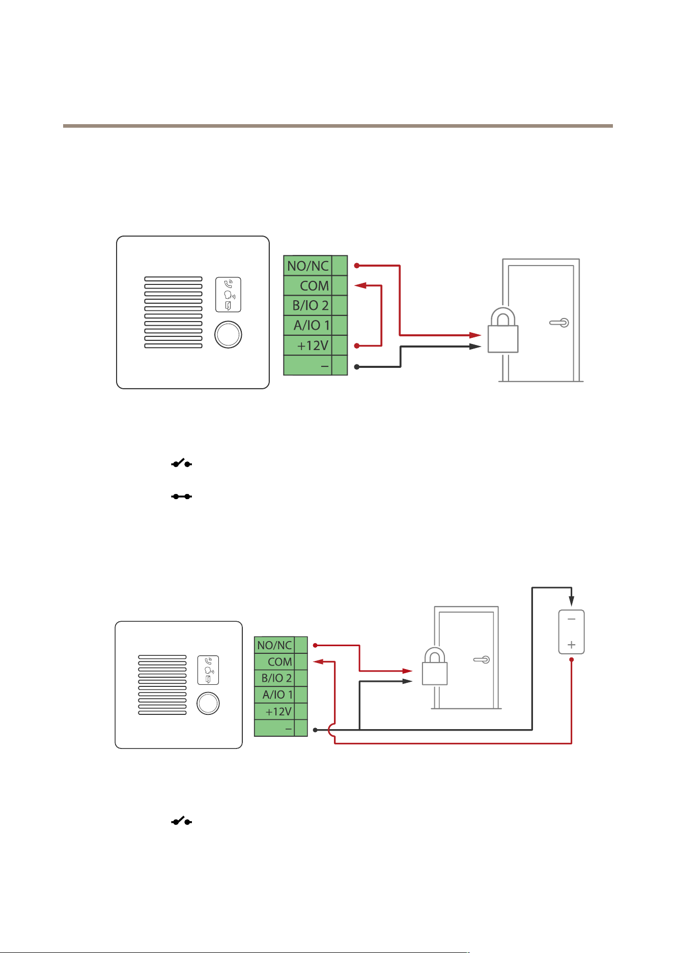
AXIS I7020 Network Inter com
Connect equipment
Connect equipment
Relay powered by P oE (12V)
1. T o check relay state, go to System > Accessories and nd the relay port.
2. Set Normal state to:
- for a fail - secure lock.
- for a fail - safe lock.
Relay powered by separate power supply
1. T o check relay state, go to System > Accessories and nd the relay port.
2. Set Normal state to:
- for a fail - secure lock.
50
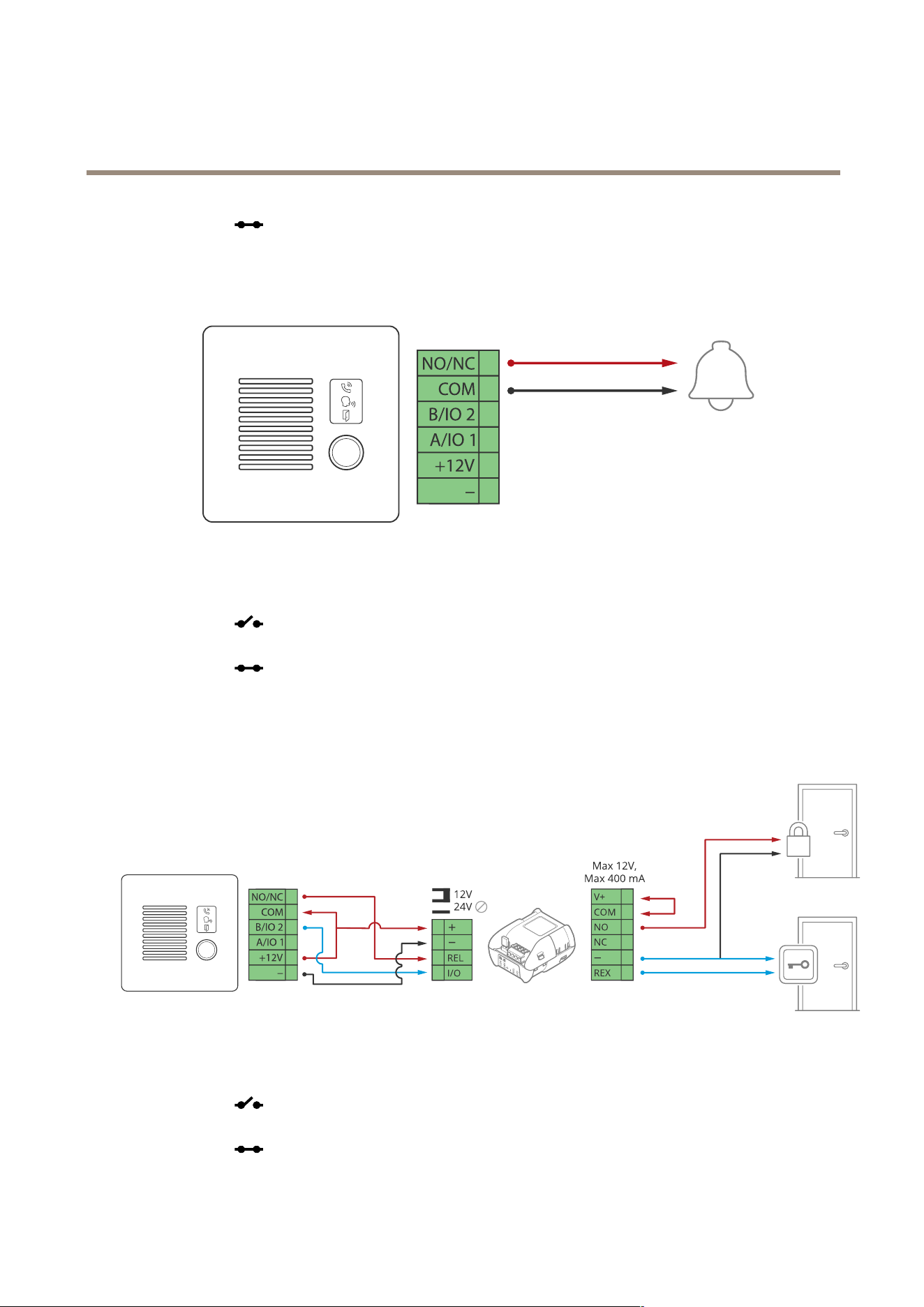
AXIS I7020 Network Inter com
Connect equipment
- for a fail - safe lock.
P otential - free relay
1. T o check relay state, go to System > Accessories and nd the relay port.
2. Set Normal state to:
- for a fail - secure lock.
- for a fail - safe lock.
12V Fail - secure lock powered by P oE from intercom
1. T o check relay state, go to System > Accessories and nd the relay port.
2. Set Normal state to:
- for a fail - secure lock.
- for a fail - safe lock.
5 1
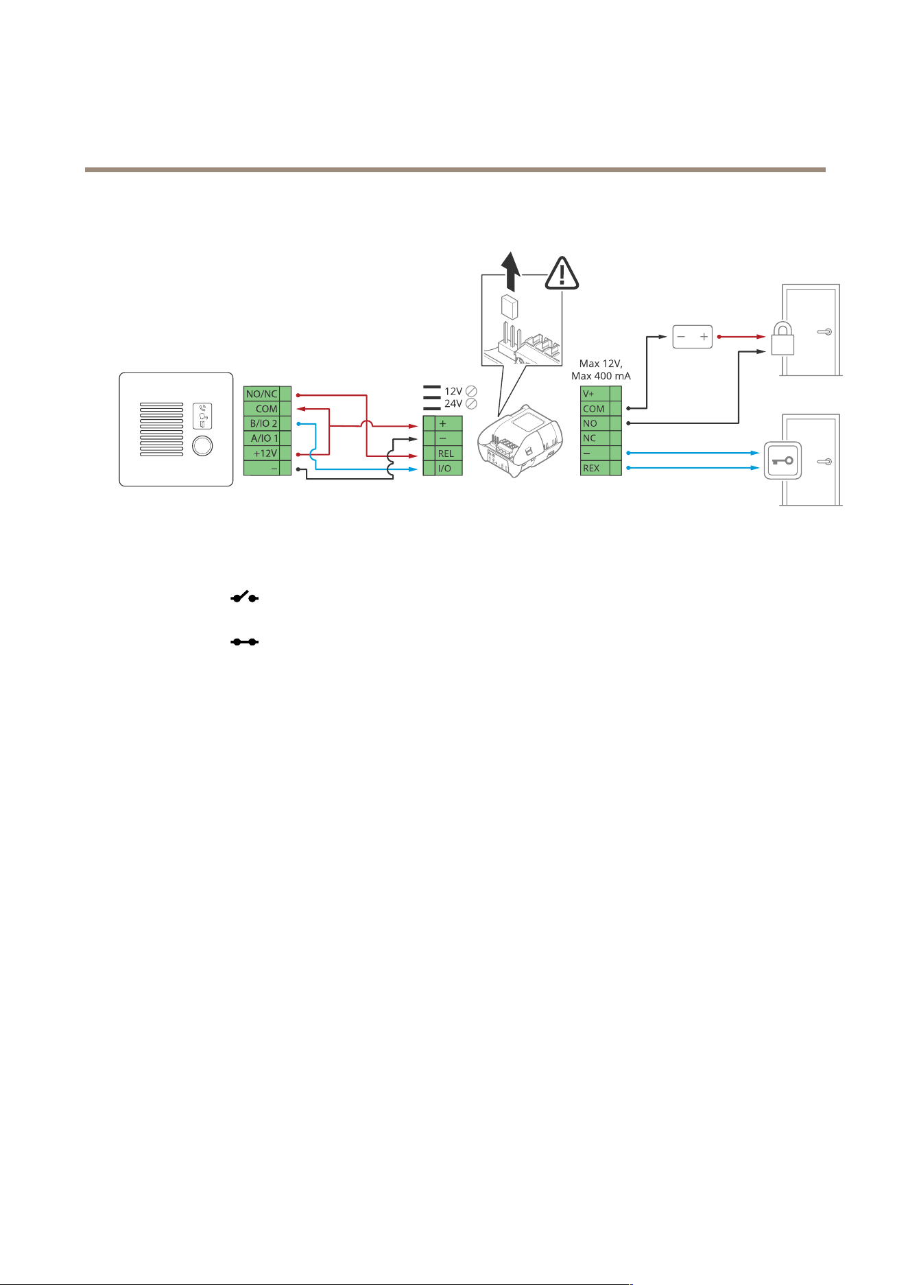
AXIS I7020 Network Inter com
Connect equipment
12V Fail - secure lock powered by external power supply
1. T o check relay state, go to System > Accessories and nd the relay port.
2. Set Normal state to:
- for a fail - secure lock.
- for a fail - safe lock.
52

AXIS I7020 Network Inter com
Clean your device
Clean your device
Y ou can clean your device with lukewarm water and detergents that contain any of the following chemicals:
• isopropanol 7 0% (IP A)
• hydrogen peroxide 3% (H
2
O
2
)
• sodium hypochlorite <5% (NaCIO)
CAUTION
Before you use a detergent, read and adhere to the safety data sheet (SDS) provided by the detergent manufacturer .
NO NO
NO
TICE TICE
TICE
• Harsh chemicals can damage the device. Don’t use chemicals such as acetone or gasoline to clean your device.
• Don’t spray detergent directly on the device. Instead, spray detergent on a nonabrasive cloth and use that to clean the device.
• Avoid cleaning in direct sunlight or elevated temperatures, since this can cause stains.
1. Use a can of compressed air to remove dust and loose dirt from the device.
2. If necessary , clean the device with a soft microber cloth dampened with lukewarm water and detergent.
3. T o avoid stains, dry the device with a clean, nonabrasive cloth.
53

AXIS I7020 Network Inter com
T r oubleshooting
T r oubleshooting
Reset to factory default settings
Important
Reset to factory default should be used with caution. A reset to factory default resets all settings, including the IP address, to
the factory default values.
T o reset the product to the factory default settings:
1. Disconnect power from the product.
2. Press and hold the control button while reconnecting power . See .
3. K eep the control button pressed for 15–30 seconds until the status LED indicator ashes amber .
4. Release the control button. The process is complete when the status LED indicator turns green. If no DHCP server is
available on the network, the device IP address will default to one of the following:
- Devices with AXIS OS 12.0 and later: Obtained from the link - local address subnet (169.254.0.0/16)
- Devices with AXIS OS 1 1.1 1 and earlier: 192.168.0.90/24
5. Use the installation and management software tools to assign an IP address, set the password, and access the device.
The installation and management software tools are available from the support pages on axis.com/support .
Y ou can also reset parameters to factory default through the device’s web interface. Go to Maintenance > Factory default and
click Default .
AXIS OS options
Axis offers device software management according to either the active track or the long - term support (L TS) tracks. Being on the
active track means continuously getting access to all the latest product features, while the L TS tracks provide a xed platform with
periodic releases focused mainly on bug xes and security updates.
Using AXIS OS from the active track is recommended if you want to access the newest features, or if you use Axis end - to - end system
offerings. The L TS tracks are recommended if you use third - party integrations, which are not continuously validated against the latest
active track. With L TS, the products can maintain cybersecurity without introducing any signicant functional changes or affecting
any existing integrations. For more detailed information about Axis device software strategy , go to axis.com/support/device - software .
Check the current AXIS OS version
AXIS OS determines the functionality of our devices. When you troubleshoot a problem, we recommend that you to start by checking
the current AXIS OS version. The latest version might contain a correction that xes your particular problem.
T o check the current AXIS OS version:
1. Go to the device’s web interface > Status .
2. Under Device info , see the AXIS OS version.
Upgrade AXIS OS
Important
• Precongured and customized settings are saved when you upgrade the device software (provided that the features are
available in the new AXIS OS) although this is not guaranteed by Axis Communications AB .
• Make sure the device remains connected to the power source throughout the upgrade process.
54

AXIS I7020 Network Inter com
T r oubleshooting
Note
When you upgrade the device with the latest AXIS OS version in the active track, the product receives the latest functionality
available. Always read the upgrade instructions and release notes available with each new release before you upgrade. T o
nd the latest AXIS OS version and the release notes, go to axis.com/support/device - software .
1. Download the AXIS OS le to your computer , available free of charge at axis.com/support/device - software .
2. Log in to the device as an administrator .
3. Go to Maintenance > AXIS OS upgrade and click Upgrade .
When the upgrade has nished, the product restarts automatically .
T echnical issues , clues , and solutions
If you can’t nd what you’re looking for here, try the troubleshooting section at axis.com/support .
Problems upgrading AXIS OS
AXIS OS upgrade failure
If the upgrade fails, the device reloads the previous version. The most common reason is that the
wrong AXIS OS le has been uploaded. Check that the name of the AXIS OS le corresponds to
your device and try again.
Problems after AXIS OS
upgrade
If you experience problems after the upgrade, roll back to the previously installed version from
the Maintenance page.
Problems setting the IP address
The device is located on a
different subnet
If the IP address intended for the device and the IP address of the computer used to access the
device are located on different subnets, you cannot set the IP address. Contact your network
administrator to obtain an IP address.
The IP address is being used
by another device
Disconnect the Axis device from the network. Run the ping command (in a Command/DOS window ,
type ping and the IP address of the device):
• If you receive: Reply from <IP address>: bytes=32; time=10...
this means that the IP address may already be in use by another device on the network.
Obtain a new IP address from the network administrator and reinstall the device.
• If you receive: Request timed out , this means that the IP address is available
for use with the Axis device. Check all cabling and reinstall the device.
P ossible IP address conict
with another device on the
same subnet
The static IP address in the Axis device is used before the DHCP server sets a dynamic address.
This means that if the same default static IP address is also used by another device, there may
be problems accessing the device.
The device can’t be accessed from a browser
Can’t log in
When HTTPS is enabled, ensure that the correct protocol (HTTP or HTTPS) is used when attempting
to log in. Y ou may need to manually type http or https in the browser’s address eld.If the
password for the root account is lost, the device must be reset to the factory default settings. See .
The IP address has been
changed by DHCP
IP addresses obtained from a DHCP server are dynamic and may change. If the IP address has been
changed, use AXIS IP Utility or AXIS Device Manager to locate the device on the network. Identify
the device using its model or serial number , or by the DNS name (if the name has been congured).If
required, a static IP address can be assigned manually . For instructions, go to axis.com/support .
Certicate error when using
IEEE 80 2.1X
For authentication to work properly , the date and time settings in the Axis device must be
synchronized with an NTP server . Go to System > Date and time .
55

AXIS I7020 Network Inter com
T r oubleshooting
The device is accessible locally but not externally
T o access the device externally , we recommend you to use one of the following applications for Windows
®
:
• AXIS Camera Station Edge: free of charge, ideal for small systems with basic surveillance needs.
• AXIS Camera Station 5: 30 - day trial version free of charge, ideal for small to mid - size systems.
• AXIS Camera Station Pro: 90 - day trial version free of charge, ideal for small to mid - size systems.
For instructions and download, go to axis.com/vms .
Can’t connect over port 8883 with MQTT over SSL
The rewall blocks trafc
using port 8883 as it’s
deemed insecure.
In some cases the server/broker might not provide a specic port for MQTT communication. It may
still be possible to use MQTT over a port normally used for HTTP/HTTPS trafc.
• If the server/broker supports W ebSocket/W ebSocket Secure (WS/WSS), typically on
port 443, use this protocol instead. Check with the server/broker provider to see if
WS/WSS is supported and which port and basepath to use.
• If the server/broker supports ALPN, the use of MQTT can be negotiated over an open
port, such as 443. Check with your server/broker provider to see if ALPN is supported
and which ALPN protocol and port to use.
P erformance considerations
When setting up your system, it is important to consider how various settings and situations affect the performance. Some factors
affect the amount of bandwidth (the bitrate) required, others can affect the frame rate, and some affect both. If the load on the
CPU reaches its maximum, this also affects the frame rate.
The following factors are the most important to consider:
• High image resolution or lower compression levels result in images containing more data which in turn affects the
bandwidth.
• Access by large numbers of Motion JPEG or unicast H.264 clients affects the bandwidth.
• Simultaneous viewing of different streams (resolution, compression) by different clients affects both frame rate and
bandwidth.
Use identical streams wherever possible to maintain a high frame rate. Stream proles can be used to ensure that
streams are identical.
• Accessing Motion JPEG and H.264 video streams simultaneously affects both frame rate and bandwidth.
• Heavy usage of event settings affects the product’s CPU load which in turn affects the frame rate.
• Using HTTPS may reduce frame rate, in particular if streaming Motion JPEG.
• Heavy network utilization due to poor infrastructure affects the bandwidth.
• Viewing on poorly performing client computers lowers perceived performance and affects frame rate.
• Running multiple AXIS Camera Application Platform (ACAP) applications simultaneously may affect the frame rate and
the general performance.
Contact support
If you need more help, go to axis.com/support .
56

AXIS I7020 Network Inter com
Safety infor mation
Safety infor mation
Hazard levels
DANGER
Indicates a hazardous situation which, if not avoided, will result in death or serious injury .
W ARNING
Indicates a hazardous situation which, if not avoided, could result in death or serious injury .
CAUTION
Indicates a hazardous situation which, if not avoided, could result in minor or moderate injury .
NO NO
NO
TICE TICE
TICE
Indicates a situation which, if not avoided, could result in damage to property .
Other message levels
Important
Indicates signicant information which is essential for the product to function correctly .
Note
Indicates useful information which helps in getting the most out of the product.
57

User manual V er . M1.9
AXIS I7 0 20 Network Intercom Date: September 20 24
© Axis Communications AB, 20 24
P art no. T1 0 2 132 15