Distributed by:
Perfect Aire, LLC
5401 Dansher Rd.
Countryside, IL 60525
844-4PA-AIRE | 844-472-2473
www.perfectaire.us
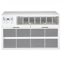
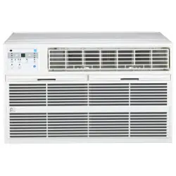
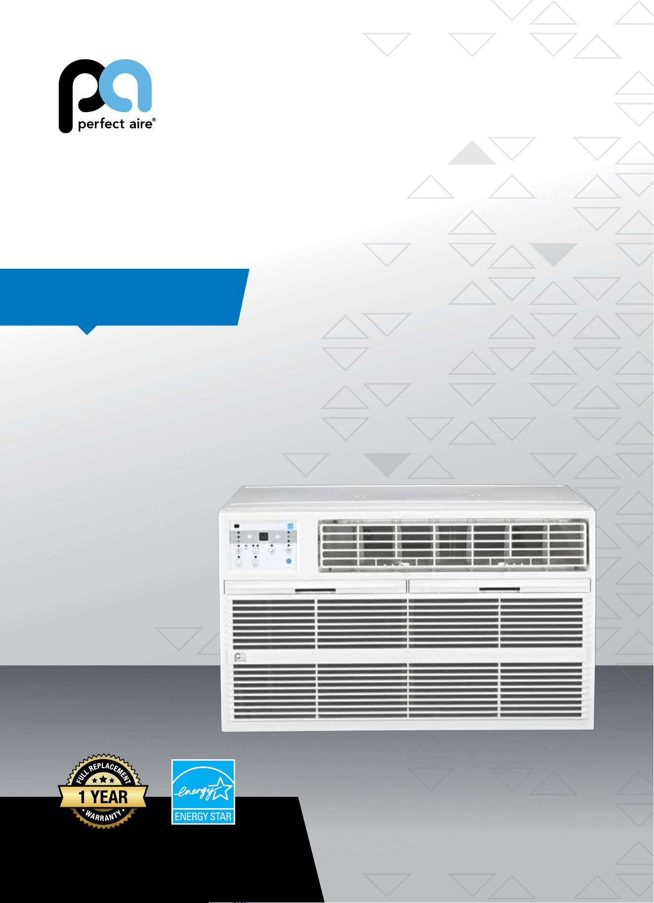
THRU-THE-WALL
AIR CONDITIONER
FOR MODELS:
4PATW8000
4PATW10000
4PATW10002
4PATW12000
4PATW12002
Before using your air conditioner, please
read this manual carefully and keep it for
future reference, along with your receipt.
Specification and performance data is subject to change without notice.
Printed in China
PA/User4PATW_ES/12132017
USER MANUAL
For your own records, please attach a copy of your sales receipt to this manual and complete the following:
Model Number: _____________________________________ Serial Number: _______________________________________
Purchase Date: ____________________________________ Store Purchased: _____________________________________
Installation Date: ___________________________________ Installation Co.: _______________________________________
Installer Name: _____________________________________ Installer Phone No.: ___________________________________
CONSUMER PRODUCT INFORMATION
SAFETY PRECAUTIONS ...................................................................1
IMPORTANT SAFETY INSTRUCTIONS ...........................................3
INSTALLATION INSTRUCTIONS .....................................................4
NORMAL SOUNDS ...........................................................................18
AIR CONDITIONER FEATURES .......................................................18
CARE AND CLEANING ....................................................................21
TROUBLESHOOTING ....................................................................... 22
CONTENTS
This manual provides the information needed for proper use and maintenance
of this air conditioner. Basic preventative care can help extend the life of this
unit. The “Troubleshooting” section in this manual contains a chart with solu-
tions to the most common problems. Referring to this section may save time
and prevent the need for a service call in the event of a problem.
CAUTIONS
● Contactanauthorizedservicetechnicianforrepairormaintenanceofthisunit.
● Contactaninstallerforinstallationofthisunitifnecessary.
● Theairconditionerisnotintendedforusebyyoungchildrenwithoutadultsupervision.Youngchildrenshouldbe
supervised to ensure that they do not play with the air conditioner.
● Disabledpersonsmayrequireassistancewithsetup.
● Ifthepowercordistobereplaced,replacementworkshouldbeperformedbyauthorizedpersonnelonly.
● Installationandrepairworkmustbeperformedinaccordancewiththenationalwiringstandardsbyauthorized
personnel only.
● Donotoperateyourairconditionerinawetroomsuchasabathroomorlaundryroom.
NOTE:Alltheillustrationsinthismanualareforexplanationpurposesonly.Unitpurchasedmaybeslightlydierent.
Thedesignandspecicationsaresubjecttochangewithoutpriornoticeforproductimprovement.ContactConsumer
Services at 844-472-2473 for details.
1
WARNINGS
Plug in power cord properly. Failuretodosomaycauseelectricshockorredueto
excess heat generation.
DO NOT operate or stop the unit by inserting or pull-
ing out the power plug directly from the wall.
Doingsomaycauseelectricshockorredueto
heat generation
DO NOT use a damaged power cord.
Doingsomaycauseelectricshockorre.Ifthepower
cord is damaged, it must be replaced by the manufactur-
eroranauthorizedservicecenterorasimilarlyqualied
personinordertoavoidahazard
DO NOT modify power cord length or share the
outlet with other appliances.
Doingsomaycauseelectricshockorredueto
heat generation.
DO NOT operate with wet hands or in
damp environment.
Doingsomaycauseelectricshock.
DO NOTdirectairowdirectlyatroomoccupants.
This could cause health issues.
Alwaysensureeectivegrounding. Incorrectgroundingmaycauseelectricshock.
DO NOT allow water to run into electric parts.
Doingsomaycausefailureofmachineorelectricshock.
Alwaysinstallcircuitbreakerandadedicated
power circuit.
Incorrectinstallationmaycausereandelectricshock.
Always unplug the unit if strange sounds, smell or
smokecomesfromtheunit.
Failuretodosomaycausereandelectricshock.
DO NOTusethesocketifitislooseordamaged.
Doingsomaycausereandelectricshock.
DO NOT open the unit during operation.
Doingsomaycauseelectricshock.
DO NOTuserearmsnearunit.
Doingsomaycausere.
DO NOT use the power cord close to
heating appliances.
Doingsomaycausereandelectricshock.
DO NOT disassemble, modify, or drill holes into
the air conditioner.
Doingsomaycausefailureandelectricshockandvoid
the manufacturer warranty.
Ventilate room before operating air conditioner if
thereisagasleakfromanotherappliancesuchas
a stove.
Failuretodosomaycauseexplosion,reandburns.
DO NOTusethepowercordnearammablegasor
combustibles,suchasgasoline,benzene,thinner,etc.
Doingsomaycauseanexplosionorre.
READ SAFETY PRECAUTIONS BEFORE INSTALLATION
Topreventinjurytotheuserorotherpeopleandpropertydamage,thefollowinginstructionsmustbefollowed.
Incorrectoperationduetoignoringofinstructionsmaycauseharmordamage.Theseriousnessisclassiedbythe
following indications.
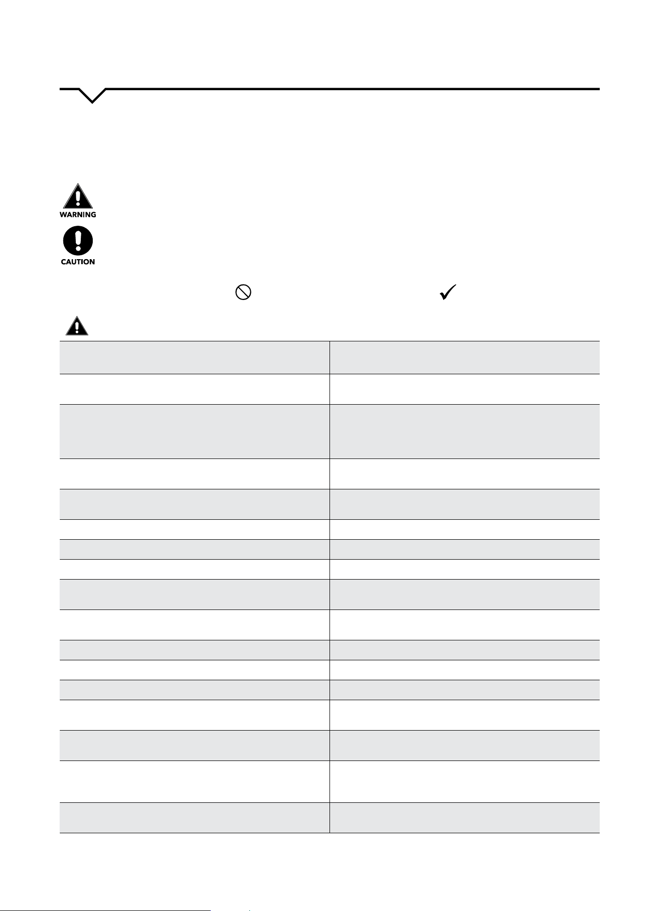
THIS SYMBOL INDICATES THAT IGNORING INSTRUCTIONS MAY CAUSE
DEATH OR SERIOUS INJURY.
NEVER DO THIS.OTHER SYMBOLS: ALWAYS DO THIS.
THIS SYMBOL INDICATES THAT IGNORING INSTRUCTIONS MAY CAUSE
MODERATE INJURY TO YOUR PERSON, OR DAMAGE TO YOUR UNIT OR
OTHER PROPERTY.
SAFETY PRECAUTIONS

2
CAUTIONS
Whenremovingairlter,DO NOT touch metal parts of
the unit.
Doingsomaycauseaninjury.
DO NOT clean with water.
Water may enter the unit and degrade the insulation
causinganelectricshock.
Ensure proper ventilation especially in rooms with a
stove or other appliances.
Failure to do so may result in an oxygen shortage.
Unitandcircuitbreaker/fusemustbeswitchedOFF
when cleaning.
CleaningunitwhenpowerisONmaycausereand
electricshockandmaycauseaninjury.
DO NOT put a pet or house plant where it will be ex-
posedtodirectairow.
Thiscouldinjurethepetorplant.
Use ONLY as intended. This unit is NOT intended to preserve precision devic-
es,food,pets,plants,andartobjects.Itmaycause
deteriorationofquality,etc.
Stop operation and close the window in severe
storms or hurricanes.
Operationwithwindowsopenmaycausemoistureto
enter the room.
Hold the plug by the head of the power plug when
takingitout.
Failuretodosomaycauseelectricshockanddam-
age.
If unit will not be used for a long period of time,
unplugorturnOFFmainpowerswitch.
Leavingpoweronmaycauseunitfailureorre.
DO NOT place obstacles around air-inlets or inside of
air-outlet.
Obstaclesmaycauseappliancefailureoraccident.
Periodicallycheckinstallationbracketfordamage. Prolonged exposure to outdoor elements may cause
damagetoinstallationbracketcausingunittofall.
Alwaysinsertlter(s)securely.Cleanlter(s)AT
LEASTonceeverytwoweeks.
Operationwithoutsecurelyinstalledltersmay
causefailure.Adirtyltercancausetheunittonot
runeciently.
Use only a soft cloth to clean the unit. Cleaners or detergents may change the color or
scratch the surface of the unit.
Usecautionwhenunpackingandinstalling. Sharpedgescouldcauseinjury.
NEVERdrinkwaterdrainedfromairconditioner.
Water from unit contains contaminants and could
cause illness.
DO NOTplaceheavyobjectsonthepowercordand
always ensure that the cord is not compressed.
Thereisdangerofreorelectricshock.
If water enters the electrical components of the unit,
turntheunitoatthepoweroutletandswitchothe
circuitbreaker.Isolatesupplybytakingthepower
plugoutandcontactaqualiedservicedtechnician.
Thereisdangerofelectricshock.
3
IMPORTANT SAFETY INSTRUCTIONS
NOTE
:
The power supply cord with this air
conditioner contains a current detection
devicedesignedtoreducetherisk
ofre.Pleaserefertothesection
“OperationofCurrentDevice”(below)
for details. In the event that the power
supply cord is damaged, it cannot be
repaired. It must be replaced by an
authorizedrepairtechnicianwithacord
from the Product Manufacturer.
WARNING
Avoidrehazardsorelectricshock.
DO NOT use an extension cord or an
adapter plug. DO NOT remove any prong
from the power cord.
OPERATION OF
CURRENT DEVICE:
The power supply cord contains a
current device that senses damage
to the power cord. To test your power
supply cord, do the following:
1. Plug in the air conditioner.
2. The power supply cord will have
TWObuttonsontheplughead.Press
theTESTbutton.Youwillnoticea
clickastheRESETbuttonpopsout.
3. Press the RESET button. Again,
youwillnoticeaclickasthebutton
engages.
4. The power supply cord is now
supplyingelectricitytotheunit.(On
some products this is also indicated
byalightontheplughead.)
WARNING
FORYOURSAFETY:Donotstoreorusegasolineorotherammable
vaporsandliquidsinthevicinityofthisoranyotherappliances.
WARNING - PREVENT ACCIDENTS
Toreducetheriskofre,electricalshock,orinjurytopersonswhenusing
your air conditioner, follow basic precautions, including the following:
● Besuretheelectricalserviceisadequateforthemodelyouhave
chosen. This information can be found on the serial plate, which is
located on the side of the cabinet and behind the grille.
● Iftheairconditioneristobeinstalledinawindow,youwillprobably
wanttocleanbothsidesoftheglassrst.Ifthewindowisatriple-
tracktypewithascreenpanelincluded,removethescreencompletely
before installation.
● Besuretheairconditionerhasbeensecurelyandcorrectlyinstalled
according to the installation instructions in this manual.
●
Save this manual for possible future use in removing or installing this unit.
● Whenhandlingtheairconditioner,becarefultoavoidcutsfromsharp
metalnsonfrontandrearcoils.
WARNING - ELECTRICAL INFORMATION
The complete electrical rating of your new room air conditioner is
statedontheserialplate.Refertotheratingwhencheckingthe
electricalrequirements.
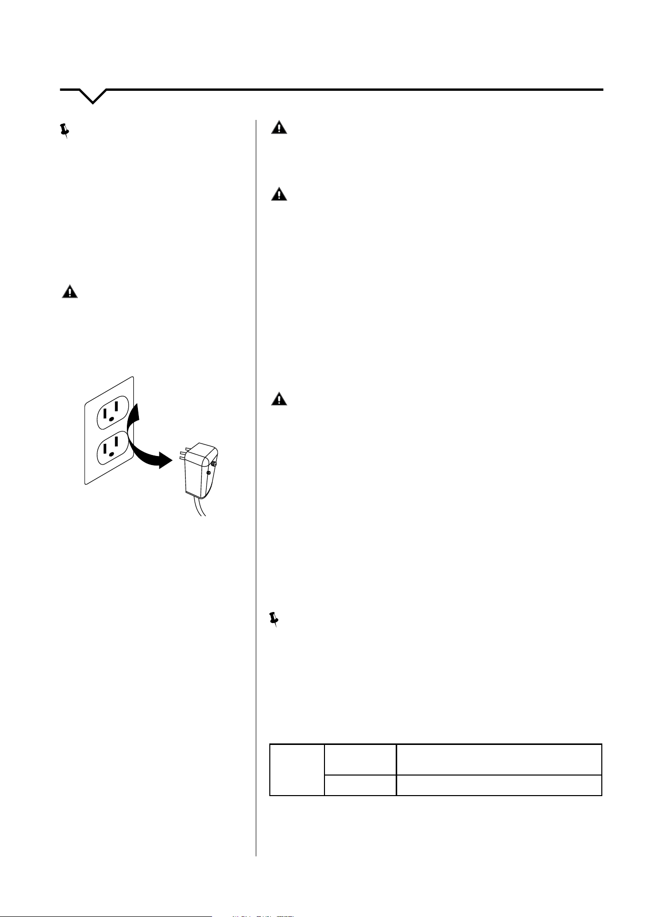
● Besuretheairconditionerisproperlygrounded.Tominimizeshock
andrehazards,propergroundingisimportant.Thepowercordis
equippedwithathree-pronggroundingplugforprotectionagainst
shockhazards.
● Yourairconditionermustbeusedinaproperlygroundedwall
receptacle.Ifthewallreceptacleyouintendtouseisnotadequately
groundedorprotectedbyatimedelayfuseorcircuitbreaker,havea
qualiedelectricianinstalltheproperreceptacle.
● Ensurethereceptacleisaccessibleaftertheunitinstallation.
● DO NOT run air conditioner without side protective cover in place. This
could result in mechanical damage within the air conditioner.
● DO NOT use an extension cord or an adapter plug.
NOTE
:
DO NOTusetheplugtoturntheunitonoro.
● AlwaysmakesuretheRESETbuttonispushedinforcorrectoperation.
● ThepowersupplymustbereplacedifitfailsresetwheneithertheTEST
button is pushed or it cannot be reset.
● Ifpowersupplycordisdamaged,itcannotberepaired.Pleasecall
Consumer Services at 844-472-2473 to assist with replacement.
NOTE: This air conditioner is designed to be operated under the
following conditions:
Cooling
Operation
Outdoor Temp:
64–109°F/18–43°C
(64–125°F/18–52°Cforspecialtropicalmodels)
Indoor Temp:
62–90°F/17–32°C
Performance may be reduced outside of these operating temperatures.
Grounding Type
Wall Receptacle
Do not, under any
circumstances, cut,
remove, or bypass the
ground prong.
Power supply cord
with 3-prong grounding
plug and current
detection device
4
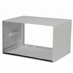
DO THIS FIRST (FOR EXISTING SLEEVE)
Note that the air conditioner dimensions are:
24.25incheswide,14.5incheshigh,and18.5inches
deep(withoutfront).
Install air conditioner according to these installation
instructions to achieve the best performance. Save
these installation instructions for future reference.
NOTE: DO NOT useanyscrewsotherthanthosespecied
in these instructions.
BEFORE YOU BEGIN
Read these instructions completely and carefully.
IMPORTANT- Save these instructions.
IMPORTANT-Observeallgoverningcodesand
ordinances.
Note to Installer- Be sure to leave these instructions with
the Consumer.
Note to Consumer- Keep these instructions for future
reference.
Skill level-Installationofthisappliancerequiresbasic
mechanicalskills.
Completion time- Approximately 1 hour.
We recommend that two people install this product.
Proper installation is the responsibility of the installer.
Product failure due to improper installation is not
covered under the Warranty.
YouMUSTuseonlysuppliedpartsanduseproper
installation procedures as described in these
instructions when installing this air conditioner.
CAUTION
DO NOT, under any circumstances, cut or remove the
third(ground)prongfromthepowercord.
DO NOT change the plug on the power cord of the
air conditioner.
Aluminum house wiring may present special problems-
consultaqualiedelectrician.
When handling unit, be careful to avoid cuts from sharp
metaledgesandaluminumnsonfrontandrearcoils.
ITEMS IN KIT
Youmaynotneedallpartslistedinthiskit.
DO NOT discard unused parts.
HARDWARE
(Included - Packed with the Unit)
ITEM
DIMENSIONS
(if applicable)
QTY.
Tapered Spacer
Blocks
17" Long 2
Centering/Support
Blocks
4½" x 3½" x 1½" 4
Plastic Divider ⅛"x4½x14½ 2
StuerSeal 1" x 1½" x 84" 1
Seal 1"x1½"x25" 3
Seal 1" x 1½" x 14" 2
Seal 1"x⅜"x25" 3
Seal 1"x⅜"x14" 2
Seal 1" x ¾" x 14" 2
TrimFrame(sidelegs) — 2
TrimFrame(top&
bottomlegs)
— 2
GroundWire(green) — 1
Toothed Washer for
Grounding Screw
— 2
Grounding Screw — 1
Grille(plastic) — 1
Grille(aluminum) — 1
Nuts(plastic) — 4
Screw Washer — 4
Screw — 4
INSTALLATION INSTRUCTIONS
5
HOW TO INSTALL
Do the following before installing the unit.
STEP 1:
IDENTIFY WALL-SLEEVE BRAND
Identify the wall-sleeve brand for your installation from the chart below.
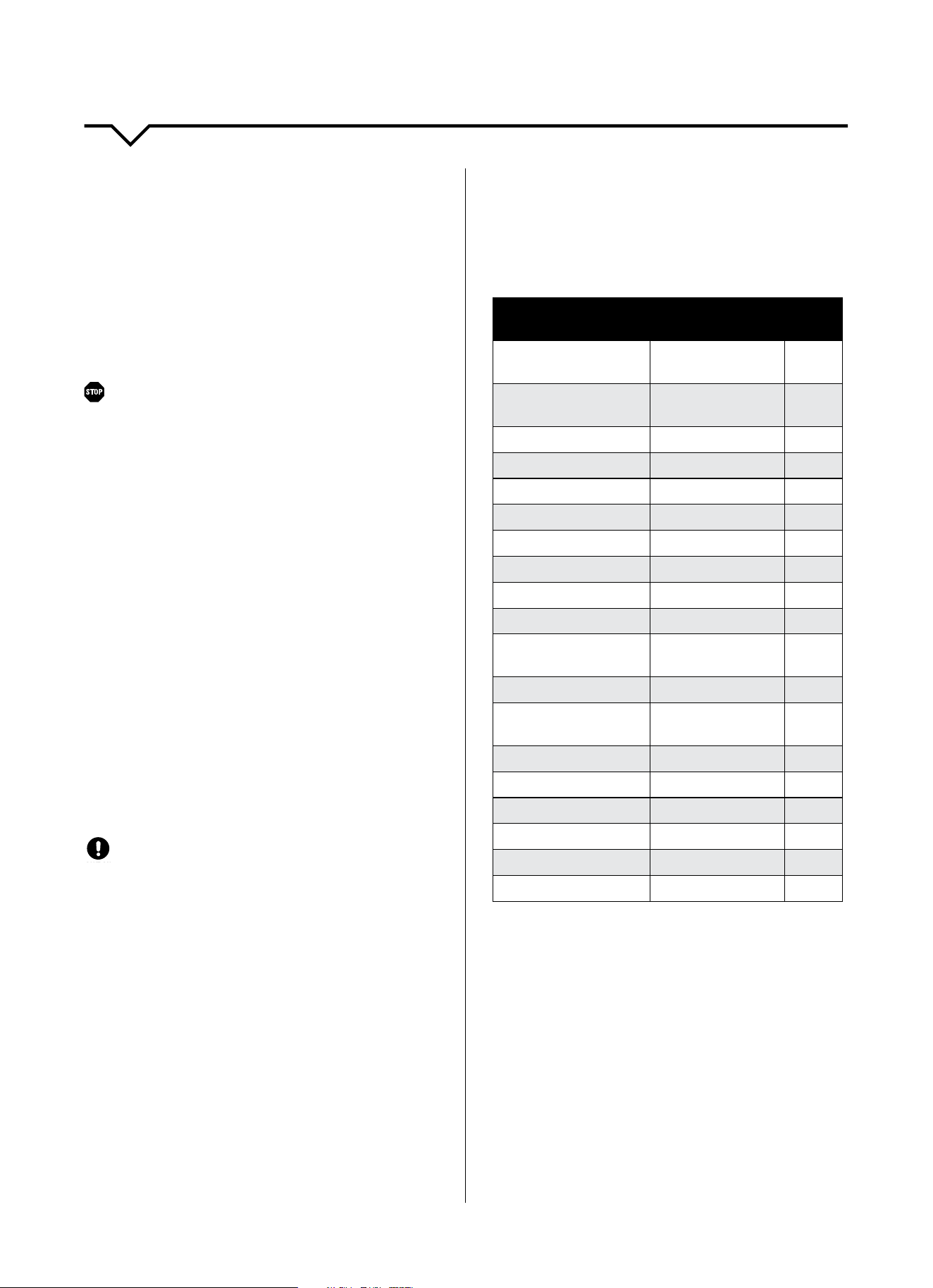
WALL SLEEVE DIMENSIONS
BRAND WIDTH HEIGHT DEPTH
NOTE:
Please verify
dimensions of your
wall sleeve with its
manufacturer before
installing your thru-
the-wall unit.
PERFECT AIRE, Frigidaire, White-
Westinghouse,Carrier(52FSeries)
25½" 15¼" 16", 17½", or 22"
General Electric, Hotpoint 26" 15⅝" 15⅞"
Whirlpool 25⅞" 16½" 17⅛"or23"
Fedders, Emerson 27" 16¾" 16¾" or 19¾"
Sears/Kenmore,Carrier(51SSeries) 25¾" 16⅞" 18⅝"
Fedders, Emerson 26¾" 15¾" 15"
Friedrich 27" 16¾" 16¾"
NOTE: All wall sleeves used to mount the new air conditioner must be in sound
structural condition and have a rear grille that securely attaches to sleeve, or
rearangethatservesasastopfortheairconditioner.
CAUTION: When the installation is complete, replacement unit MUST have a
rearward slope as shown.
STEP 2:
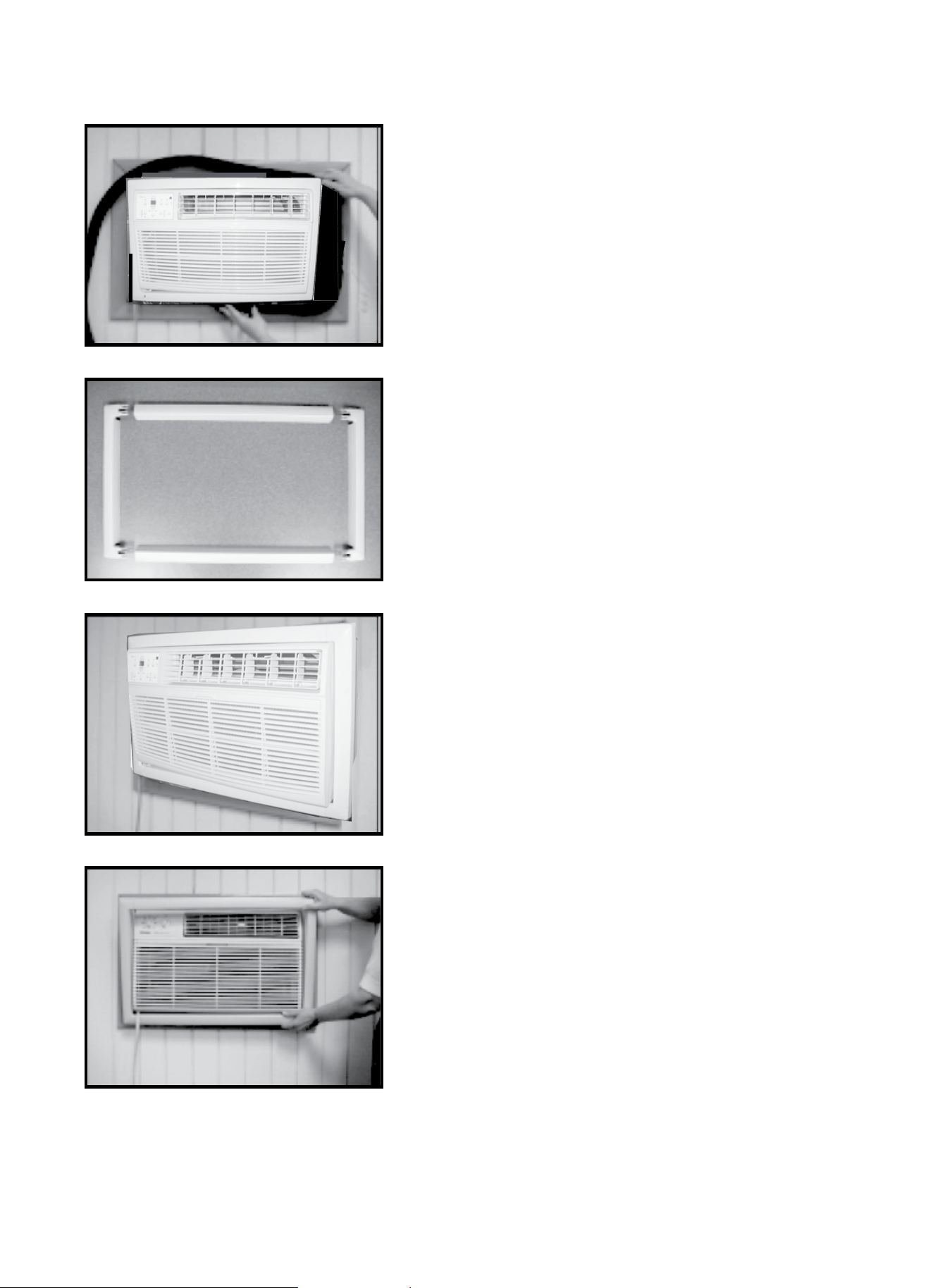
REMOVE OLD AIR CONDITIONER
Remove old air conditioner from wall sleeve and prepare wall sleeve as follows:
• Cleaninterior.(Donotdisturbseals.)
• Wallsleevemustbesecurelyfastenedinwallbeforeinstallingthenewairconditioner.Drivemorenailsorscrews
through sleeve into wall if needed.
• Repairpaintifneeded.
STEP 3:
DRILL A ⅛" CLEARANCE HOLE
Ifnotexisting,drilla⅛"clearanceholeforgroundingscrewthroughleftsideofsleeveinaclearareaabout3inches
maximum(tosuit)backfromfrontedgeofsleeve(asshownbelow)usinggroundscrewandtoothedwasher.Pullloose
end of ground wire out front of sleeve, and temporarily bend it down and around lower edge of sleeve. The ground wire
will be attached to frame of air conditioner later once it is installed.
.
WALL SLEEVE TO UNIT
SLEEVE GROUNDING
3"
MAX
1"
1/8"
HOLE
REAR
LEVEL
FRONT
UNIT
WALL
SLEEVE
1/4" to 5/16"
6
STEP 4:
PREPARE THE WALL SLEEVE
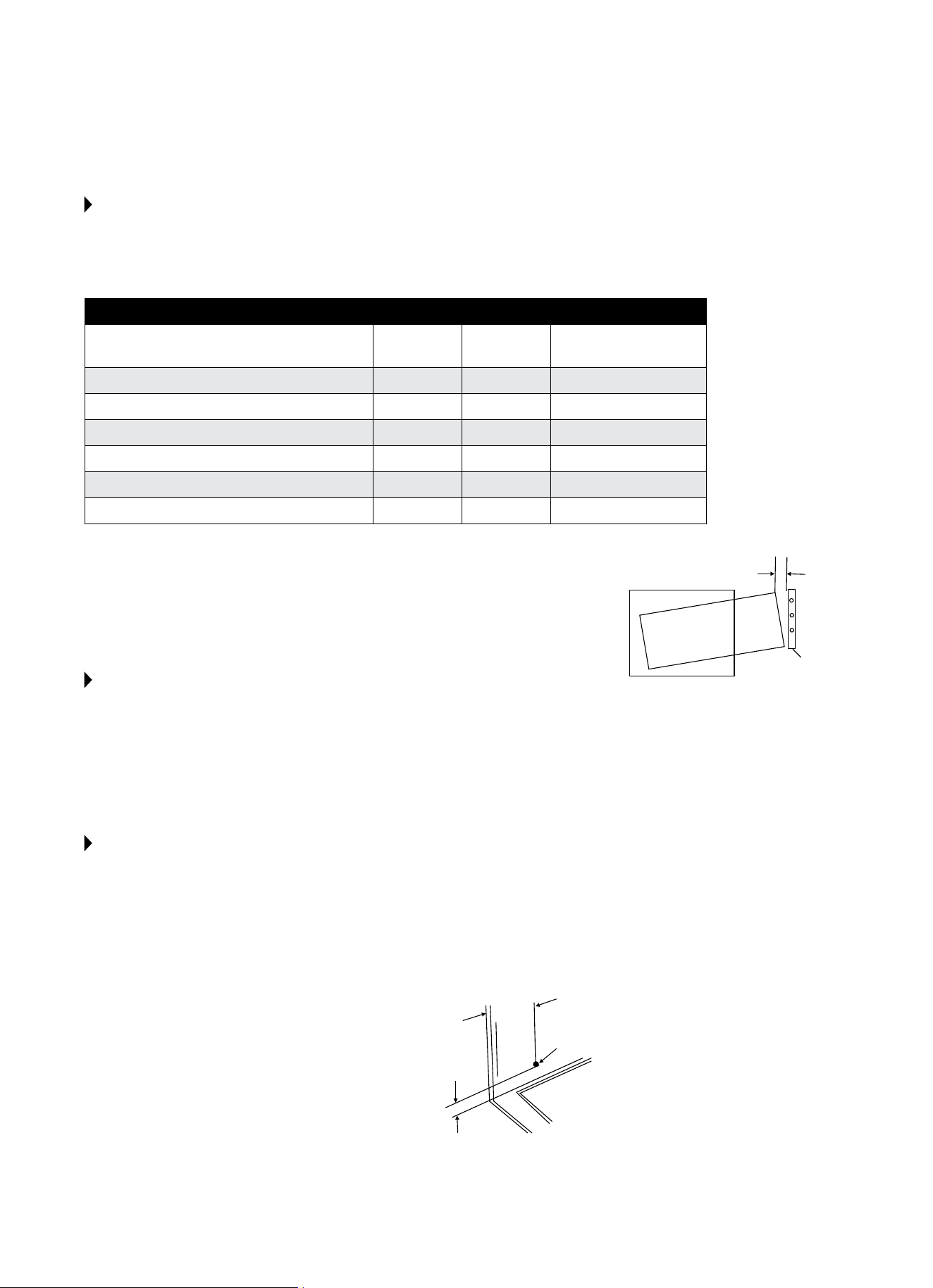
Prepare the wall sleeve for installation of the new unit per the following brand instructions.
BRAND DEPTH PAGE
#1
PERFECT AIRE, Frigidaire, White-
Westinghouse,Carrier(52FSeries)
16"&17½" 7
#2 Fedders 19¾” 8
#3 Fedders or Friedrich 16¾” 9
#4 GeneralElectric/Hotpoint 16⅞" 10
#5 SearsorCarrier(51SSeries) 18⅝" 11
#6 Whirlpool 17⅛” 12
#7 Whirlpool 23" 13
#8 Emerson 15" 14
#9 White-Westinghouse, Frigidaire 22" 15
STEP 5:
IDENTIFY YOUR WALL SLEEVE’S BRAND
Identify your wall sleeve’s brand and install new unit into wall sleeve using the applicable instructions on the
following pages.
STEP 6:
ATTACH GROUND WIRE TO NEW UNIT
To attach ground wire to the new unit, remove the screw from the left side front.
STEP 7:
ASSEMBLE AND INSTALL THE TRIM FRAME (SEE INSTRUCTIONS)
IMPORTANT:
• Theunit’sincreasedperformancecharacteristicsresultfromhavingtworearairintakes.
• Itisveryimportantthattheseinstallationinstructionsarefollowedtoensurethatyourunitcanoperateat
maximumeciency.
• Ifthisisanexistingsleeveandthereisanexistingreargrille,itneedstobereplacedbyonethathasbeenshipped
withtheunitintheaccessorykit.
For increased efficiency, utilize the provided louvered rear panel.
Installation of the new grille provided with the unit:
1. Remove the existing grille.
2. Placethegrille(includedwiththenewairconditioner)towardstherearof
the sleeve.
3. Marktheholepositions.
4. Drillthroughthesleeve’sangeswitha1/8inchdrillbit.
5. Attachthenewgrillewithself-threadingscrewsandwashers(not
included).
6. ItisVERYIMPORTANTthatthegrilleisplacedexactlyasshowninthe
picture on the right.
7. Most decorative exterior grilles may be left in place as long as the proper
interior art direction grille is installed.
7
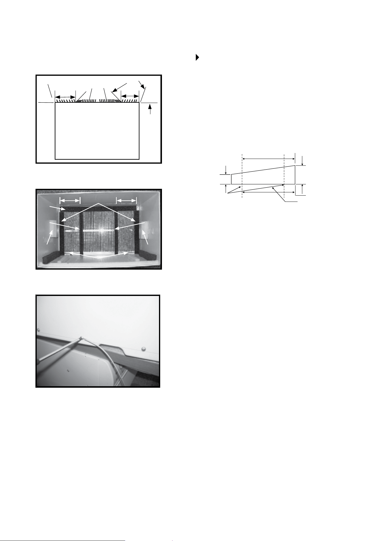
WALL SLEEVE BRANDS:
#1 PERFECT AIRE, WHITE
WESTINGHOUSE, FRIGIDAIRE,
CARRIER 52F SERIES
16 IN. & 17½ IN. DEEP
1. Remove existing rear grille and replace with provided
louvered panel. Install as shown here.
NOTE:Youmayneedtodrillholesinangeofexisting
sleeve to match new rear grille.
2. Attach(1)1ʺx⅜ʺx25ʺ long seal in the center at the
topofthesleeve.Removethebackingpaperandpress
into position.
3. Attach(2)1ʺx⅜ʺ x 14ʺ long seals to the left and right
sides of the sleeve.
4. Attach(1)1ʺ x ¾ʺ x 14ʺlongsealvertically4.5ʺ from the
left side of the sleeve. Attach the other 1ʺ x ¾ʺ x 14ʺ long
seal 4ʺ from the right side of the sleeve.
5. Centerunitandgentlyslideunitintosleeve.
6. Beforeslidingallofthewayback,removesecondscrew
from front on left side of the unit.
7. Remove the plastic washer from the screw.
8. Screw and attach the other end of the ground wire to
theunitasshowninpicture.Makesurethatthetoothed
washer is against the cabinet.
9. Slide the unit completely to the rear to ensure a
goodseal,makingsurethegroundwiredoesnot
become tangled.
10. Seal&frametheunitasdescribedonpage17.
11. Ifyouhavedicultywithmountingthegrilletothe
sleeve, follow the instructions for direct mounting on
page 16.
REAR LOUVERS
4.5ʺ 4ʺ
80° 80°
80°80°
30° 30°
TOP VIEW
4.5ʺ 4ʺ
2
3
4

8
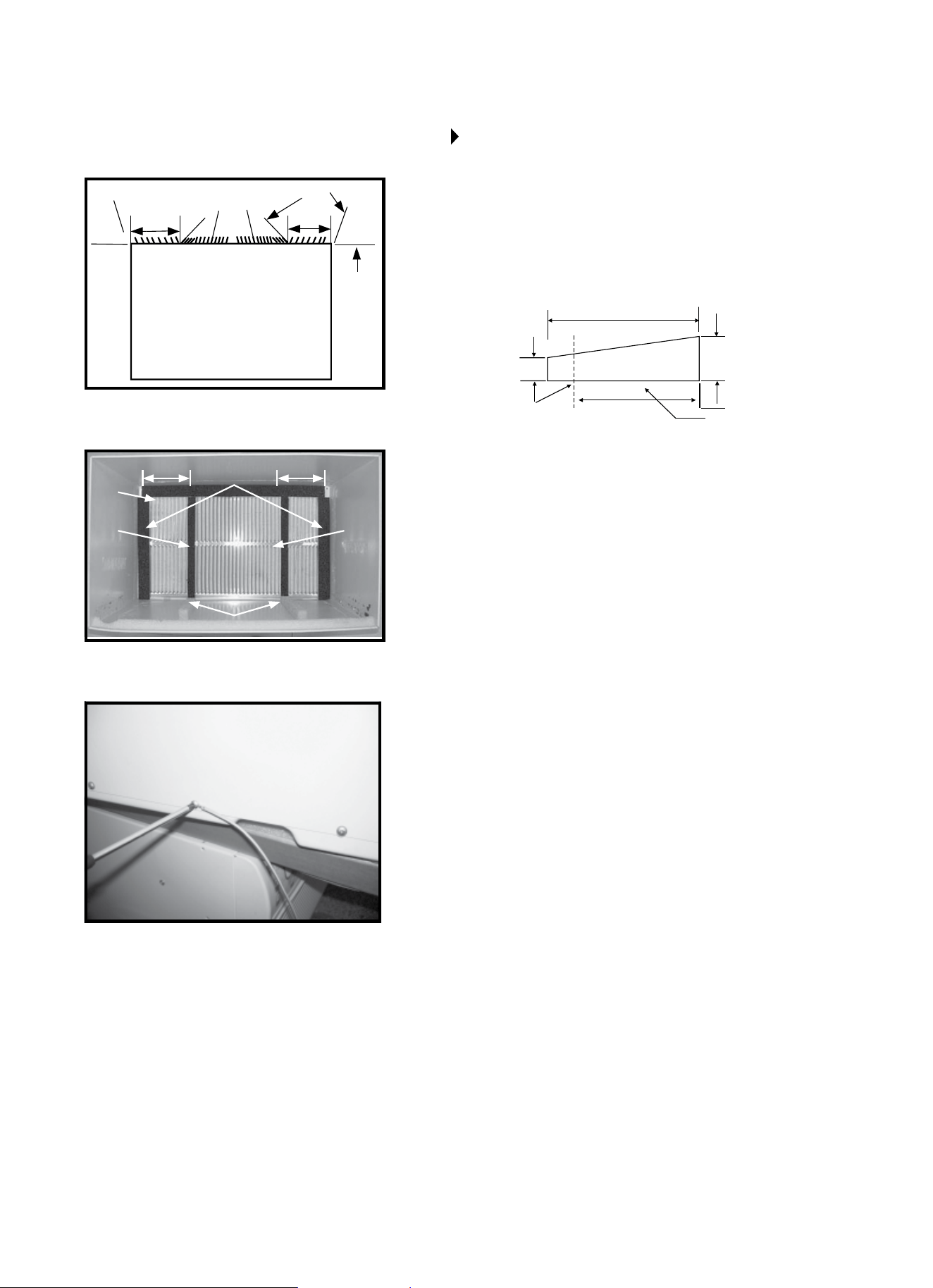
#2 FEDDERS
19¾ IN. DEEP
1. Remove existing rear grille and replace with provided
louvered panel. Install as shown here.
NOTE:Youmayneedtodrillholesinangeofexisting
sleeve to match new rear grille.
2. Attach(2)4¼ʺ x 3½ʺ x 1½ʺcentering/supportblocks,
one on each side wall. Place in center of side walls
with the tapered end facing the opening.
3. Cutthe(2)17ʺTaperedSpacerBlocksasshownbelow
into two pieces.
TAPERED
SPACER BLOCK
CUT HERE
PROTECTION
PAPER BACKING
3/4ʺ
17
ʺ
1ʺ
4ʺ
4. The 4ʺ section is placed in front of the rib on base
withthetaperedendfacingthebackofthesleeve.
The remaining portion behind the rib again is sloping
toward the rear of the sleeve. This helps induce a
rearward slope on the unit.
5. Attach(1)1ʺx⅜ʺx25ʺ long seal in the center at the
topofthesleeve.Removethebackingpaperand
press into position.
6. Attach(2)1ʺx⅜ʺ x 14ʺ long seals to the left and right
sides of the sleeve.
7. Cut(2)1ʺx⅜ʺx25ʺ long seal to 14ʺ long and attach it
to the vertical sections of the rear grille as shown.
8. Gently slide unit into sleeve.
9. Beforeslidingallofthewayback,removesecond
screw from front on left side of the unit.
10. Remove the plastic washer from the screw.
11. Screw and attach the other end of the ground wire
totheunitasshowninpicture.Makesurethatthe
toothed washer is against the cabinet.
12. Slide the unit completely to the rear to ensure a
goodseal,makingsurethegroundwiredoesnot
become tangled.
13. Seal&frametheunitasdescribedonpage17.
14. Ifyouhavedicultywithmountingthegrilletothe
sleeve, follow the instructions for direct mounting on
page 16.
WALL SLEEVE BRANDS:
REAR LOUVERS
4.5ʺ 4ʺ
80° 80°
80°80°
30° 30°
TOP VIEW
4.5ʺ 4ʺ
5
7
2 2
7
6
3
9
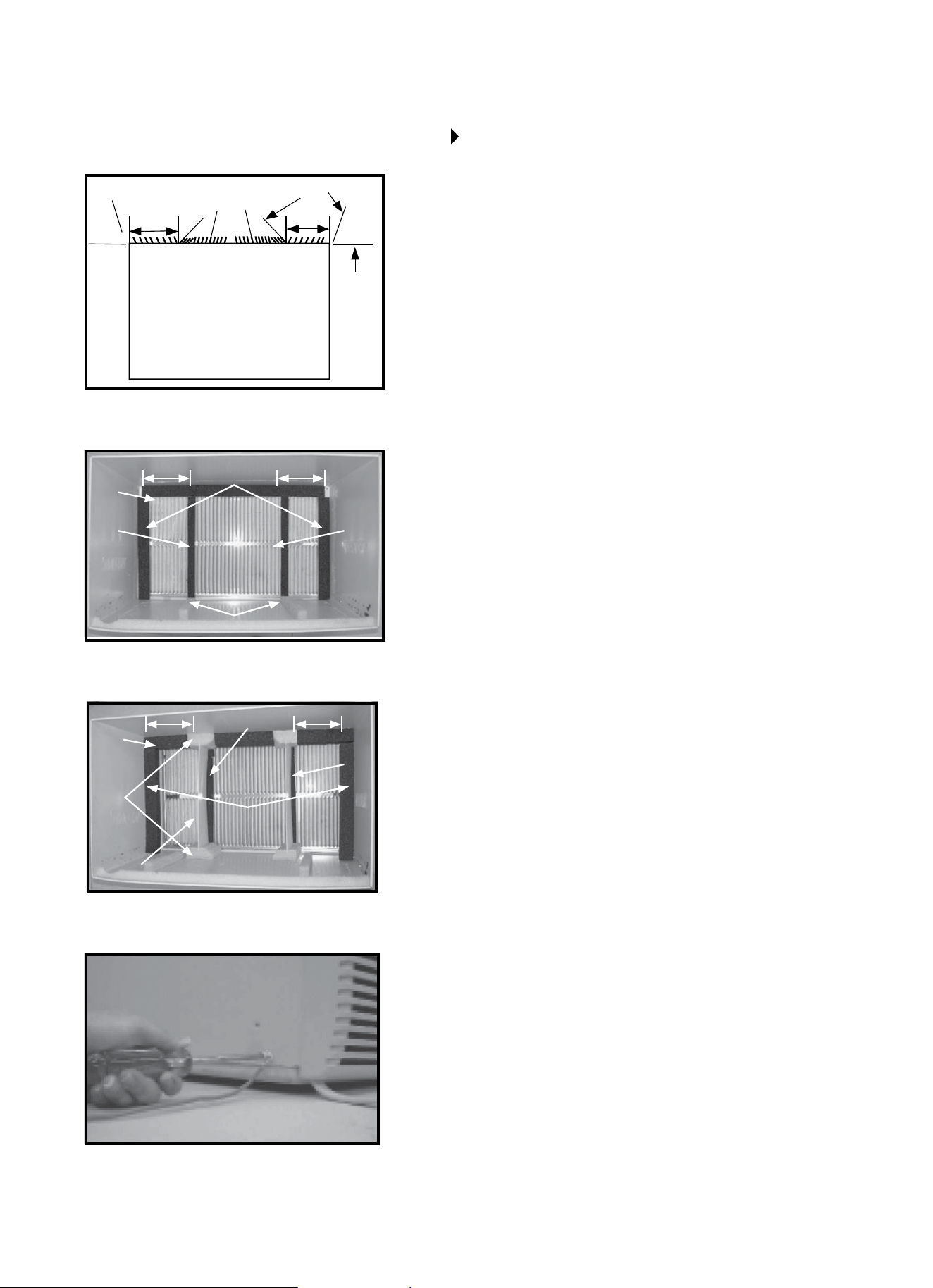
#3 FEDDERS OR FRIEDRICH
16¾ IN. DEEP
1. Remove existing rear grille and replace with provided
louvered panel. Install as shown here.
NOTE:Youmayneedtodrillholesinangeofexisting
sleeve to match new rear grille.
2. Attach(2)4¼ʺ x 3½ʺ x 1½ʺcentering/supportblocks,
one on each side wall. Place in center of side walls
with the tapered end facing the opening.
3. Cutthe(2)17ʺTaperedSpacerBlocksasshownbelow
into two pieces.
TAPERED
SPACER BLOCK
CUT HERE
PROTECTION
PAPER BACKING
3/4ʺ
17
ʺ
1ʺ
12½ʺ
2½ʺ
4. The 2½ʺ section is placed in front of the rib on base
withthetaperedendfacingthebackofthesleeve.Cut
the remaining portion to 12½ʺ and place behind the rib
again, sloping toward the rear of the sleeve. This helps
to induce a rearward slope on the unit.
5. Attach(1)1ʺx⅜ʺx25ʺ long seal in the center at the
topofthesleeve.Removethebackingpaperand
press into position.
6. Attach(2)1ʺx⅜ʺ x 14ʺ long seals to the left and right
sides of the sleeve.
7. Cut(2)1ʺx⅜ʺx25ʺ long seal to 14ʺ long and attach it
to the vertical sections of the rear grille as shown.
8. Gently slide unit into sleeve.
9. Beforeslidingallofthewayback,removesecond
screw from front on left side of the unit.
10. Remove the plastic washer from the screw.
11. Screw and attach the other end of the ground wire
totheunitasshowninpicture.Makesurethatthe
toothed washer is against the cabinet.
12. Slide the unit completely to the rear to ensure a
goodseal,makingsurethegroundwiredoesnot
become tangled.
13. Seal&frametheunitasdescribedonpage17.
14. Ifyouhavedicultywithmountingthegrilletothe
sleeve, follow the instructions for direct mounting on
page 16.
WALL SLEEVE BRANDS:
REAR LOUVERS
4.5ʺ 4ʺ
80° 80°
80°80°
30° 30°
TOP VIEW
4.5ʺ 4ʺ
5
7
2 2
7
6
3

10
#4 GENERAL ELECTRIC
OR HOTPOINT
16
7
/8 IN. DEEP
1. Remove existing rear grille and replace with provided
louvered panel. Install as shown here.
NOTE:Youmayneedtodrillholesinangeofexisting
sleeve to match new rear grille.
2. Cutthe(2)17ʺTaperedSpacerBlocksasshownbelow
into two pieces.
TAPERED
SPACER BLOCK
CUT HERE
PROTECTION
PAPER BACKING
3/4ʺ
17ʺ
1ʺ
13ʺ
3. Install 13ʺ section as shown with the tapered end
½ʺfromthebackofthesleeve.Thishelpsinducea
rearward slope on the unit.
4. Attach(1)1ʺx⅜ʺx25ʺ long seal in the center at the
topofthesleeve.Removethebackingpaperand
press into position.
5. Attach(2)1ʺx⅜ʺ x 14ʺ long seals to the left and right
sides of the sleeve.
6. Cut(2)1ʺx⅜ʺx25ʺ long seal to 14ʺ long and attach
to the vertical sections of the rear grille as shown.
7. Center unit and gently slide unit into sleeve.
8. Beforeslidingallofthewayback,removesecond
screw from front on left side of unit.
9. Remove the plastic washer from the screw.
10. Screw and attach the other end of the ground wire
totheunitasshowninpicture.Makesurethatthe
toothed washer is against the cabinet.
11. Slide the unit completely to the rear to ensure a
goodseal,makingsurethegroundwiredoesnot
become tangled.
12. Seal&frametheunitasdescribedonpage17.
13. Ifyouhavedicultywithmountingthegrilletothe
sleeve, follow the instructions for direct mounting on
page 16.
WALL SLEEVE BRANDS:
REAR LOUVERS
4.5ʺ 4ʺ
80° 80°
80°80°
30° 30°
TOP VIEW
4.5ʺ 4ʺ
4
6 6
5
2

11
#5 SEARS OR CARRIER 51S SERIES
18
5
/8 IN. DEEP
1. Remove existing rear grille and replace with provided
louvered panel. Install as shown here.
NOTE:Youmayneedtodrillholesinangeofexisting
sleeve to match new rear grille.
2. Install(2)TaperedSpacerBlockstotheoorofthe
sleeveasshown.DONOTCUTTHEBLOCKS.This
helps induce a rearward slope on the unit.
3. Install as shown with the tapered end ½ʺ from the
backofthesleeve.Thishelpsinducearearwardslope
on the unit.
4. Attach(1)1ʺx⅜ʺx25ʺ long seal in the center at the
topofthesleeve.Removethebackingpaperand
press into position.
5. Attach(2)1ʺx⅜ʺ x 14ʺ long seals to the left and right
sides of the sleeve.
6. Cut(2)1ʺx⅜ʺx25ʺ long seal to 14ʺ long and attach it
to the vertical sections of the rear grille as shown.
7. Center unit and gently slide unit into sleeve.
8. Beforeslidingallofthewayback,removesecond
screw from front on left side of the unit.
9. Remove the plastic washer from the screw.
10. Screw and attach the other end of the ground wire
totheunitasshowninpicture.Makesurethatthe
toothed washer is against the cabinet.
11. Slide the unit completely to the rear to ensure a
goodseal,makingsurethegroundwiredoesnot
become tangled.
12. Seal&frametheunitasdescribedonpage17.
13. Ifyouhavedicultywithmountingthegrilletothe
sleeve, follow the instructions for direct mounting on
page 16.
WALL SLEEVE BRANDS:
REAR LOUVERS
4.5ʺ 4ʺ
80° 80°
80°80°
30° 30°
TOP VIEW
4.5ʺ 4ʺ
4
6 6
5
2
12
#6 WHIRLPOOL
17
1
/8 IN. DEEP
1. Remove existing rear grille and replace with provided
louvered panel. Install as shown here.
NOTE:Youmayneedtodrillholesinangeofexisting
sleeve to match new rear grille.
2. Cut(2)17ʺTaperedSpacerBlocksasshownbelowinto
two pieces.
TAPERED
SPACER BLOCK
CUT HERE
PROTECTION
PAPER BACKING
3/4ʺ
17
ʺ
1ʺ
13ʺ
3. Install 13ʺsectiontotheoorofthesleeveasshown.
This helps induce a rearward slope on the unit.
4. Attach(1)1ʺx⅜ʺx25ʺ long seal in the center at the top
ofthesleeve.Removethebackingpaperandpressinto
position.
5. Attach(2)1ʺx⅜ʺ x 14ʺ long seals to the left and right
sides of the sleeve.
6. Cut(2)1ʺx⅜ʺx25ʺ long seal to 14ʺ long and attach it to
the vertical sections of the rear grille as shown.
7. Center unit and gently slide unit into sleeve.
8. Beforeslidingallofthewayback,removesecondscrew
from front on left side of the unit.
9. Remove the plastic washer from the screw.
10. Screw and attach the other end of the ground wire to
theunitasshowninpicture.Makesurethatthetoothed
washer is against the cabinet.
11. Slide the unit completely to the rear to ensure a
goodseal,makingsurethegroundwiredoesnot
become tangled.
12. Seal&frametheunitasdescribedonpage17.
13. Ifyouhavedicultywithmountingthegrilletothe
sleeve, follow the instructions for direct mounting on
page 16.
WALL SLEEVE BRANDS:
REAR LOUVERS
4.5ʺ 4ʺ
80° 80°
80°80°
30° 30°
TOP VIEW
4.5ʺ 4ʺ
4
6 6
5
2
13
#7 WHIRLPOOL
23 IN. DEEP
1. Remove existing rear grille and replace with provided
louvered panel. Install as shown here.
NOTE:Youmayneedtodrillholesinangeofexisting
sleeve to match new rear grille.
BECAUSE OF THE INCREASED UNIT DEPTH, FIRST TRY DRY
FITTING USING METHODS DESCRIBED BELOW:
2. Place(2)1ʺ x 1½ʺ x 14ʺ seals against each side.
3. Gentlyslideunitinandcheckifamountextendingfrom
thesleeveissucientoncethetrimframeisattached.
4. IfpositionisOK,removeunitandproceedtothenext
step. If not, go to step 9.
5. Attach(1)1ʺ x 1½ʺx25ʺ long seal in the center at the
topofthesleeve.Removethebackingpaperandpress
into position.
6. Attach(2)1ʺ x 1½ʺ x 14ʺ seals to the left and right sides
of the sleeve.
7. Cut(2)1ʺx⅜ʺx25ʺ long seals to 14ʺ long and attach to
the vertical sections of the grille as shown.
8. Attachthetaperedspacerblockstotheoorofthe
sleeve.Nowgotostep15.
USE THESE NEXT STEPS IF THE UNIT REQUIRES EXTRA
EXTENSION INTO THE ROOM.
9. Attach 1ʺ x ¾ʺ x 14ʺ long seal over the solid vertical
portion of the rear grille.
10. Attach(2)4½ʺ x 3½ʺ x 1½ʺfoamblockswiththeslot
overlapping the seal above.
11. Installthedividerintotheslotsofthefoamblocks.You
mayneedtotrimthelengthtosize.
12. Repeat steps 9 through 11 for the other vertical shown
portion of the grille as shown.
13. Attach(2)1″x1½″x14″sealsalongthesidesofthe
sleeveagainmakingsureallsealsareush.
14. Cutthe1″x1½″x25″sealtotthetopofthesleeve.
Thepiecesmustbettedushtotheedgeofthedivider.
15. Centerunitandgentlyslideinsleeve.
16. Beforeslidingallthewayback,removerstscrewfrom
front on left side of unit.
17. Remove the plastic washer from the screw.
18. Screw and attach the other end of the ground wire to
theunitasshowninpicture.Makesurethatthetoothed
washer is against the cabinet.
19. Slide the unit completely to the rear to ensure a
goodseal,makingsurethegroundwiredoesnot
become tangled.
20. Seal&frametheunitasdescribedonpage17.
21. Ifyouhavedicultywithmountingthegrilletothe
sleeve, follow the instructions for direct mounting on
page 16.
WALL SLEEVE BRANDS:
REAR LOUVERS
4.5ʺ 4ʺ
80° 80°
80°80°
30° 30°
TOP VIEW
4.5ʺ
4.5ʺ
4ʺ
4ʺ
7
14
10
11
6 7
12
6
9
13
2

14
WALL SLEEVE BRANDS:
#8 EMERSON
15 IN. DEEP
1. Remove existing rear grille and replace with provided
louvered panel. Install as shown here.
NOTE:Youmayneedtodrillholesinangeofexisting
sleeve to match new rear grille.
2. Attach(1)1ʺx⅜ʺx25ʺ long seal in the center at the
topofthesleeve.Removethebackingpaperand
press into position.
3. Attachthe(2)1ʺx⅜ʺ x 14ʺ long seals to the left and
right sides of the sleeve.
4. Cut(2)1ʺx⅜ʺx25ʺ long seals to 14ʺ long and attach
to the vertical sections of the rear grille as shown.
5. Attach(2)4½ʺ x 3½ʺ x1½ʺcentering/supportblocks,
one on each side wall. Place in center of side wall with
the tapered end facing the opening.
6. Gently slide unit into sleeve.
7. Beforeslidingallthewayback,removesecondscrew
from front on left side of unit.
8. Remove the plastic washer from the screw.
9. Screw and attach the other end of the ground wire
totheunitasshowninpicture.Makesurethatthe
toothed washer is against the cabinet.
10. Slide the unit completely to the rear to ensure a good
seal,makingsurethegroundwiredoesnotbecome
tangled.
11. Seal&frametheunitasdescribedonpage17.
12. Ifyouhavedicultywithmountingthegrilletothe
sleeve, follow the instructions for direct mounting on
page 16.
REAR LOUVERS
4.5ʺ 4ʺ
80° 80°
80°80°
30° 30°
TOP VIEW
4.5ʺ 4ʺ
2
45
3

15
#9 WHITE WESTINGHOUSE,
FRIGIDAIRE
22 IN. DEEP
1. Remove existing rear grille as shown and replace with
provided louvered panel. Install as shown here.
NOTE:Youmayneedtodrillholesinangeofexisting
sleeve to match new rear grille.
BECAUSE OF THE INCREASED UNIT DEPTH, FIRST TRY DRY
FITTING USING METHODS DESCRIBED BELOW:
2. Place(2)1ʺ x 1½ʺ x 14ʺ seals against each side.
3. Gentlyslideunitinandcheckifamountextendingfrom
thesleeveissucientoncethetrimframeisattached.
4. IfpositionisOK,removeunitandproceedtothenext
step. If not, go to step 8.
5. Attach(1)1ʺ x 1½ʺx15ʺ long seal to the left side of the
sleeveand(1)1ʺ x 1½ʺx15ʺ seal to the right side of the
sleeve.
6. Cut(2)1ʺ x 1½ʺx25ʺ long seals to 14ʺ long and attach
totheverticallytothereargrille4.5ʺ from the left side
and 4ʺ from the right side.
7. Attach(1)1ʺ x 1½ʺx25ʺ long seal in the center at the
topofthesleeve.Removethebackingpaperandpress
into position. Proceed to step 14.
USE THESE NEXT STEPS IF THE UNIT REQUIRES EXTRA
EXTENSION INTO THE ROOM.
8. Attach 1ʺ x ¾ʺ x 14ʺ long seal over the solid vertical
portion of the rear grille.
9. Attach(2)4½ʺ x 3½ʺ x 1½ʺfoamblockswiththeslot
overlapping the seal above.
10. Installthedividerintotheslotsofthefoamblocks.You
mayneedtotrimthelengthtosize.
11. Repeat steps 8 through 10 for the other vertical shown
portion of the grille as shown.
12. Attach(2)1″x1½″x14″sealsalongthesidesofthe
sleeveagainmakingsureallsealsareush.
13. Cutthe1″x1½″x25″sealtotthetopofthesleeve.
Thepiecesmustbettedushtotheedgeofthedivider.
14. Center unit and gently slide in sleeve.
15. Beforeslidingallthewayback,removerstscrewfrom
front on left side of unit.
16. Remove the plastic washer from the screw.
17. Screw and attach the other end of the ground wire to
theunitasshowninpicture.Makesurethatthetoothed
washer is against the cabinet.
18. Slide the unit completely to the rear to ensure a
goodseal,makingsurethegroundwiredoesnot
become tangled.
19. Seal&frametheunitasdescribedonpage17.
20. Ifyouhavedicultywithmountingthegrilletothe
sleeve, follow the instructions for direct mounting on
page 16.
WALL SLEEVE BRANDS:
REAR LOUVERS
4.5ʺ 4ʺ
80° 80°
80°80°
30° 30°
TOP VIEW
4.5ʺ
4.5ʺ
4ʺ
4ʺ
7
13
9
10
6 6
11
5
8
12
2
16
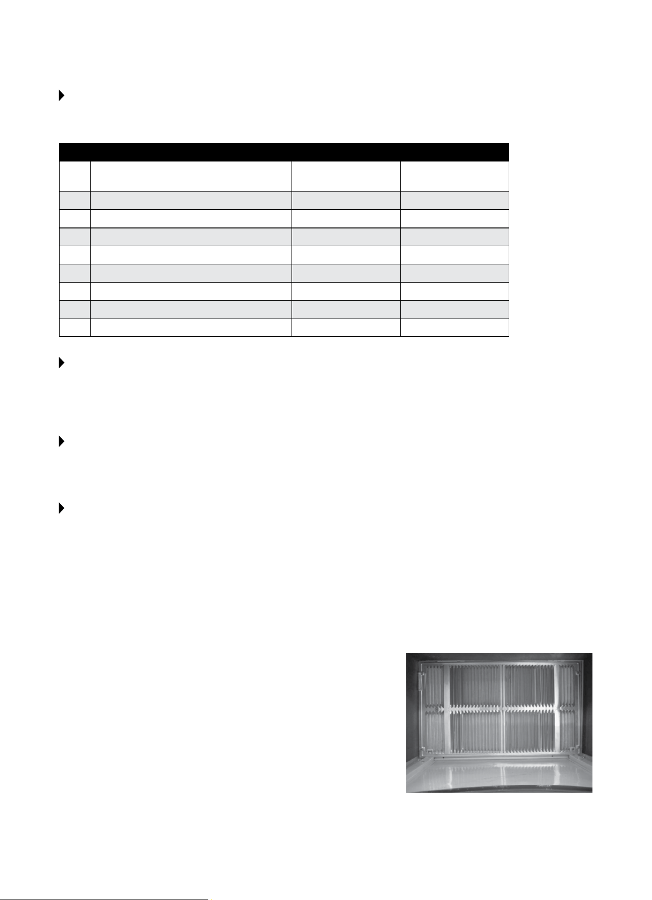
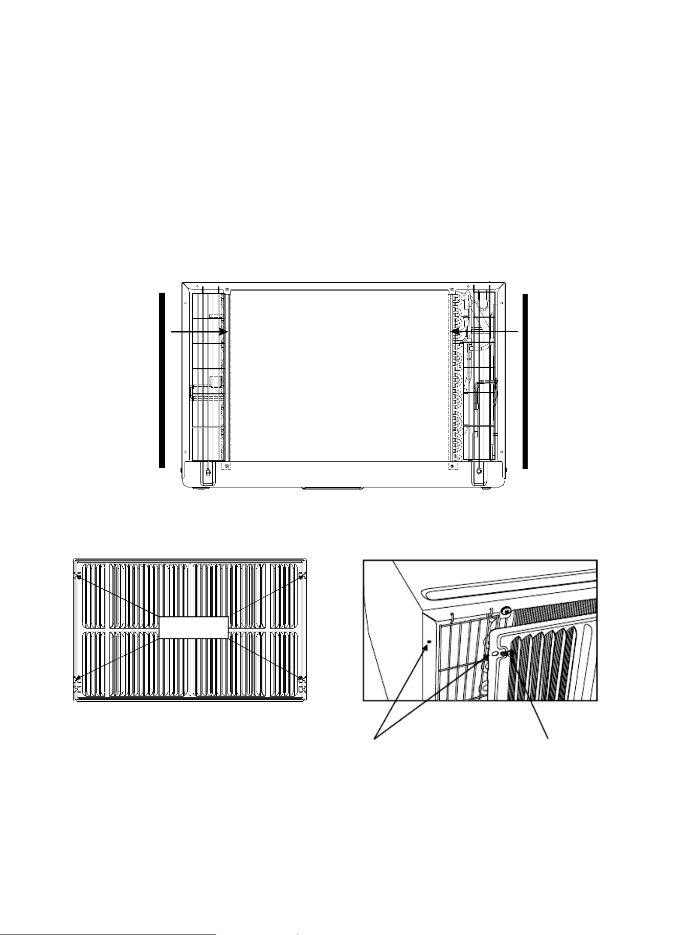
DIRECT UNIT MOUNTING
The previous directions are the preferable way to mount the new rear grille. The unit’s performance is slightly better and
the possibility of drafts is reduced. As a last resort, direct mounting of the grille to the unit can be considered.
NOTE: The grille must be installed prior to inserting the unit into the sleeve.
1. Attachthe2sealpieces(1″x3/8″x14″)asshowninFig.1.
2. Positionthegrilleovertherearoftheunitmakingsurethat:
a. The double set of screw holes are at the bottom.
b.Thensofthegrillearepointedawayfromtheunit.
3. Alignthetopofthegrillewiththetopoftheunitandensurethattheoverhangoneachsideisequal.
4. Iftheunithasnotbeenpre-drilled(somemodels),carefullydrill4-1/8″holesthroughthegrilleandintothesideange
oftheunitapproximately1½″to2″fromthetopandbottomasinFig.2andFig.3.(Becarefulnottodrillintocopper
heatexchangercoils).
5. Install4-#8selftappingscrewstoaxthegrilletotheunit.
6. Insert the unit into the sleeve.
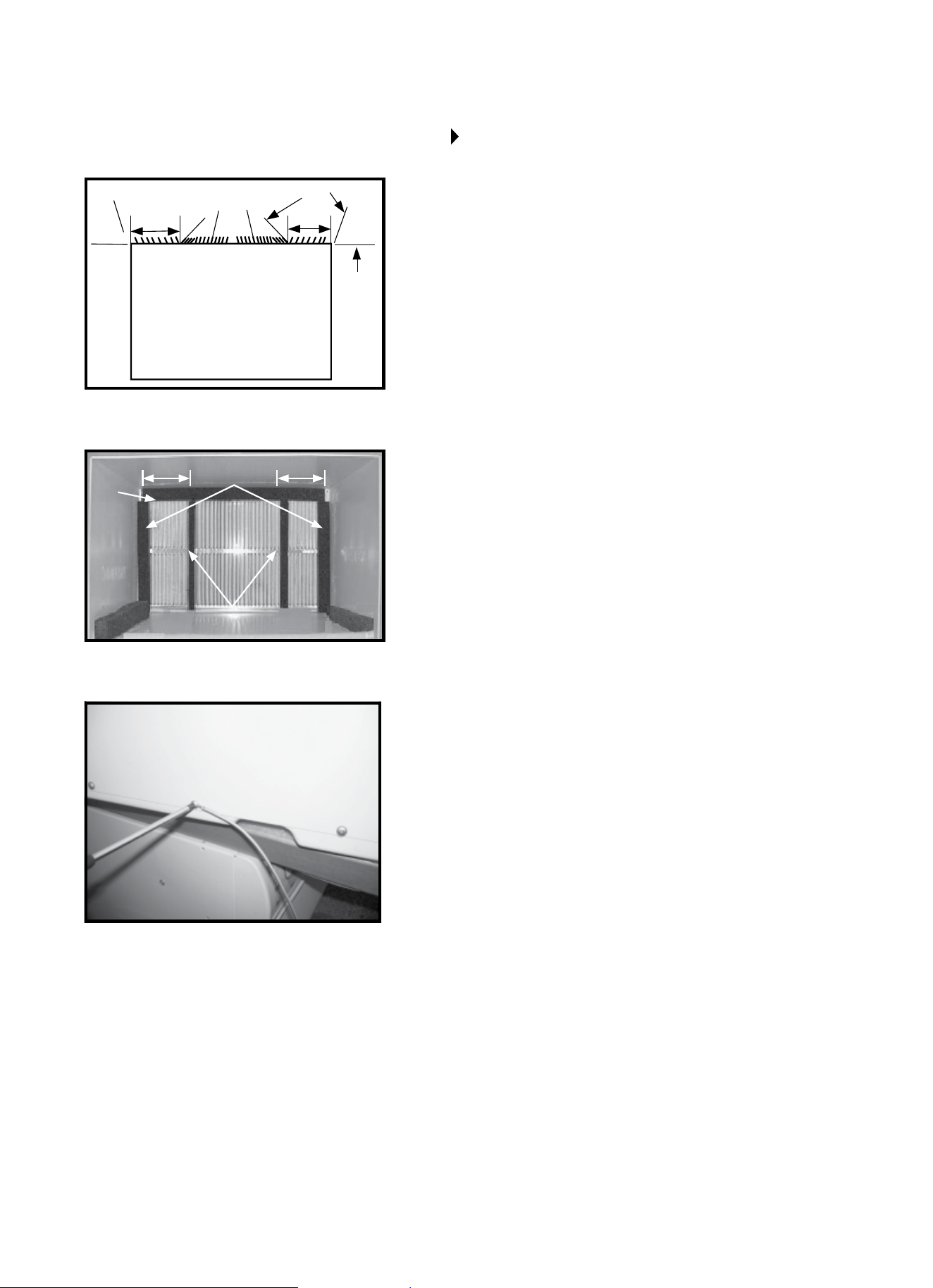
FIG. 1
Seal
1/8ʺ Hole
Grille & Flange
#8 Screw
Grille Screws
Location
Seal
FIG. 2 FIG. 3
17
1. Install the 1ʺ x 1½ʺ x 84ʺlongstuer-sealbetweenthewall
sleeveandtheunit.Aatbladedscrewdriverorputtyknife
is recommended.
2. Assemble the trim frame by inserting top and bottom pieces
into side pieces and snapping into place.
3. Pullcordthroughtrimframe,thenslideinunituntilush
with wall.
18
NORMAL SOUNDS
VIBRATION
Unitmayvibrateandmake
noise because of poor wall
construction or incorrect
installation.ThisDOESNOT
indicate a defective unit.
PINGING OR SWITCHING
Droplets of water hitting
condenser during normal
operation may cause “pinging”
or “switching” sounds.
HIGH PITCHED CHATTER
Higheciencycompressors
may have a high pitched chatter
during the cooling cycle.
SOUND OF RUSHING AIR
At the front of the unit,
the sound of rushing air
being moved by the fan
may be heard.
GURGLE/HISS
“Gurgling” or “hissing”
noise may be heard due
to refrigerant passing
through evaporator during
normal operation.
NOTE: Allofthepicturesinthismanualareforexplanatorypurposesonly.Theactualshape/lookof
theairconditionerpurchasedmaybeslightlydierent,buttheoperationsandfunctionsaresimilar.
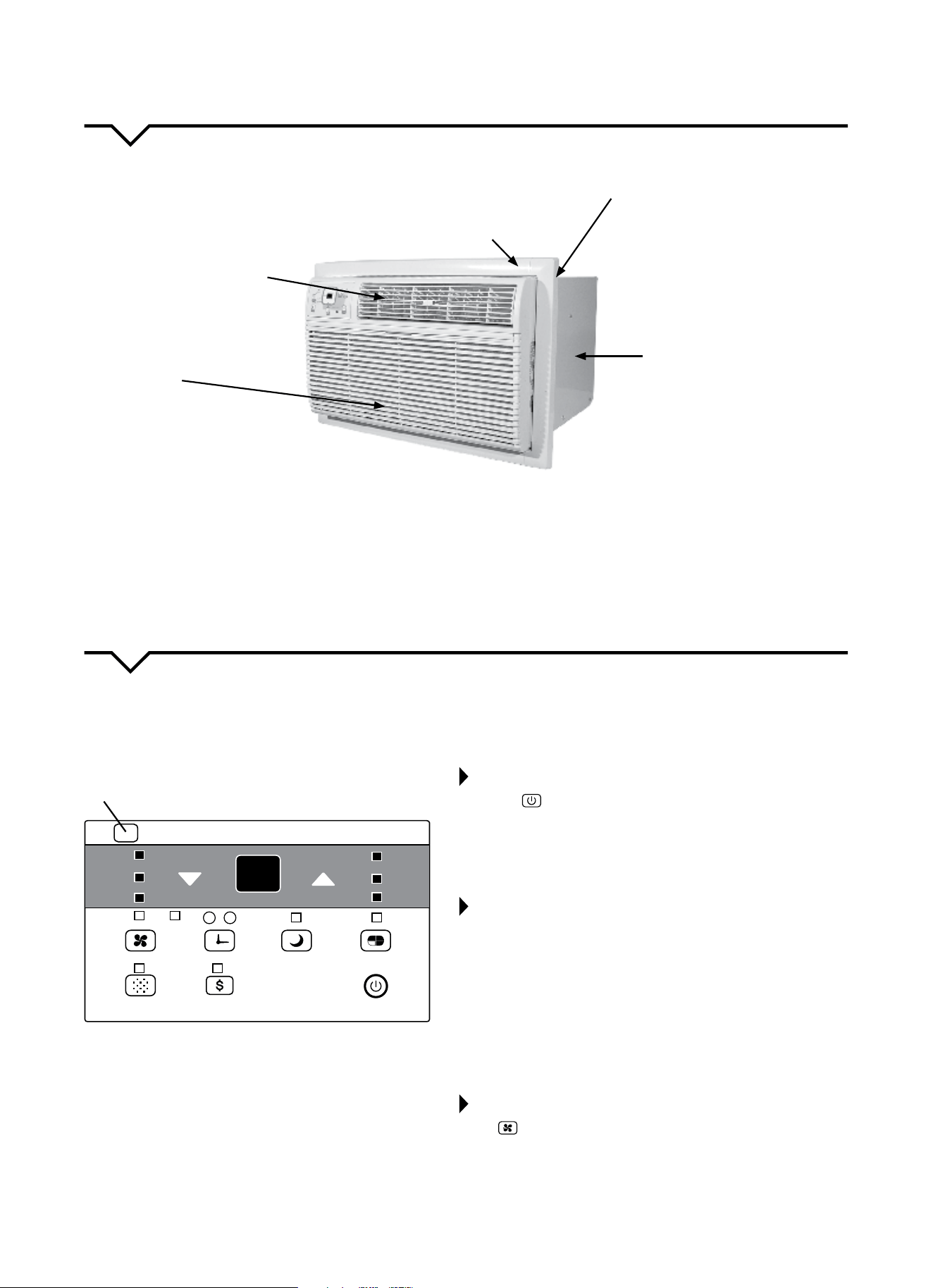
AIR CONDITIONER FEATURES
Thoroughlyfamiliarizeyourselfwiththecontrolpanelshownbelowandallofitsfunctions.Afterwards,followthe
symbolforthefunctionsyoudesireBEFOREoperatingtheunit.Thisunitcanbecontrolledbytheunitcontrolorthe
remote control.
Remote Signal
Receptor
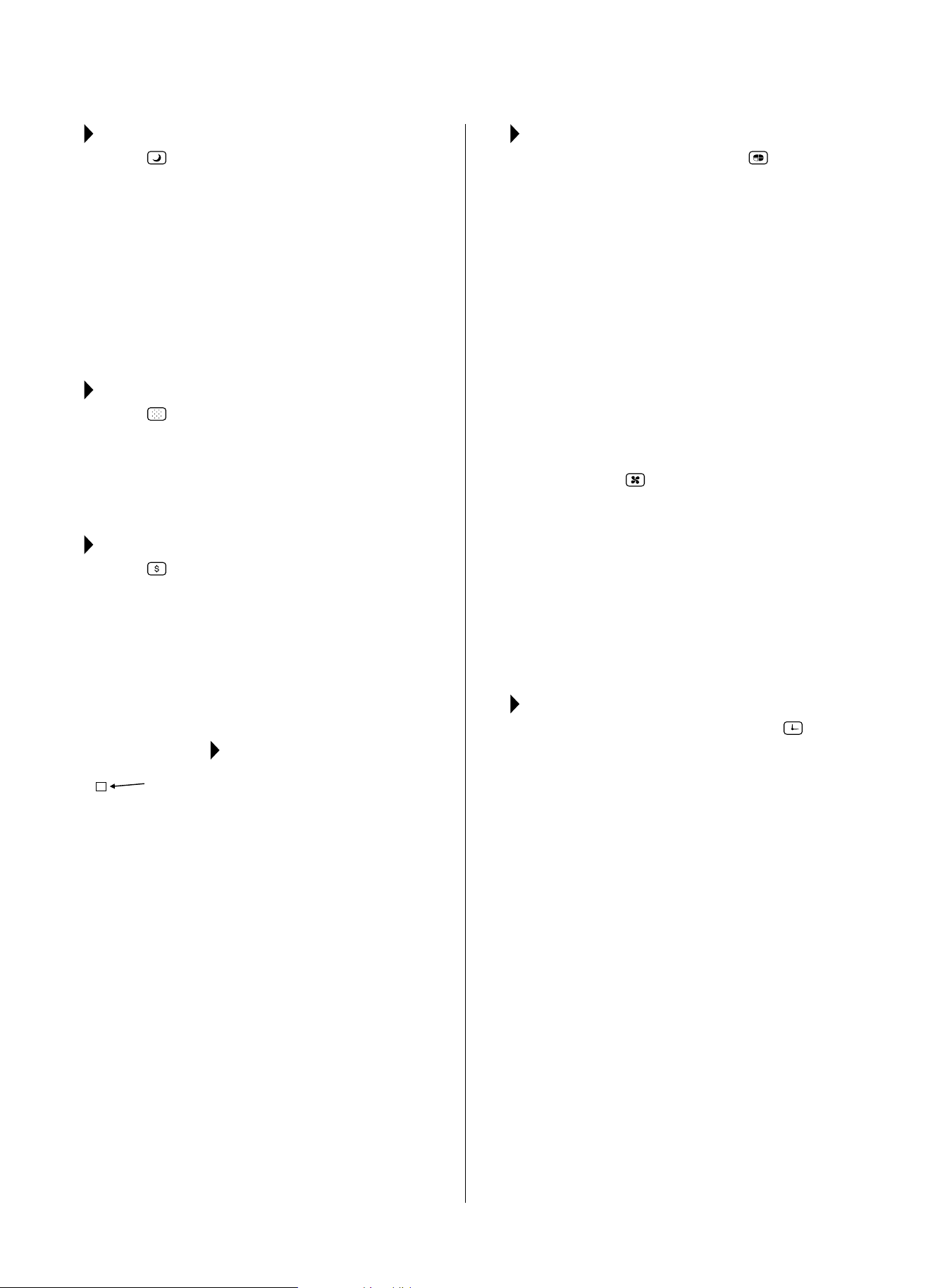
TO TURN UNIT ON OR OFF:
Press the ON/OFFbuttontoturntheunitonoro.
NOTE: The unit will automatically initiate the Energy Saver
functionunderCOOL,DRYandAUTO(onlyAUTO-COOLING
andAUTO-FANmodes).
TO CHANGE TEMPERATURE SETTING:
Press the
/
UP/DOWNbuttonstochangethe
temperature setting.
NOTE: PressorholdeitherUP(
)orDOWN(
)button
until the desired temperature is seen on the display. The
temperature will be automatically maintained anywhere
between62°F(17°C)and86°F(30°C).Ifyouwantthedisplay
toreadtheactualroomtemperature,see“ToOperateonFan
Only”section.
TO ADJUST FAN SPEED:
Press to select the Fan Speed in four steps: Auto, Low,
Med or High. Each time the button is pressed, the fan speed
isshifted.InDRYmode,thefanspeedisautomatically
controlled at Low.
UNIT CONTROL PANEL
Auto
Low
Med
High
Auto
Cool
Dry
Fan
TEMP/TIMER
On O
Sleep
Timer
Mode
Check
Filter
Energy
Saver
Fan
Follow
Me
19
SLEEP FEATURE:
Press the SLEEP button to initiate the SLEEP
mode. In this mode, the selected temperature will
increaseby2°F(1°C)30minutesafterthemode
is selected. The temperature will then increase
(cool)byanother2°F(1°C)afteranadditional30
minutes. This new temperature will be maintained
for 6 hours before it returns to the originally selected
temperature. This ends the SLEEP mode and the
unit will continue to operate as originally
programmed. The SLEEP mode program can be
canceled at any time during operation by pressing
the SLEEP button again.
CHECK FILTER FEATURE:
Press the CHECK FILTER button to initiate this
feature. This feature is a reminder to clean the Air
Filterformoreecientoperation.TheLED(light)will
illuminateafter250hoursofoperation.Toresetafter
cleaningthelter,presstheCHECK FILTER button
andthelightwillgoo.
ENERGY SAVER FEATURE:
Press the ENERGYSAVER button to initiate this
function. This function is available on COOL, DRY
and AUTO(onlyAUTO-COOLINGand AUTO-FAN)
modes. In this mode, the fan will continue to run for 3
minutesafterthecompressorshutso.Thefanthen
cycles on for 2 minutes, at 10 minute intervals, until
the room temperature is above the set temperature,
atwhichtimethecompressorturnsbackonand
cooling starts.
FOLLOW ME FEATURE:
This feature can ONLY be activated
from the remote control. The
remote control serves as a remote
thermostat allowing for precise
temperature control at its location.
To activate the Follow Me feature, point the remote
control toward the unit and press the FOLLOWME
button. The remote displays the actual temperature
at its location. The remote control will send this
signal to the air conditioner every 3 minutes until the
FOLLOWME button is pressed again. If the unit does
not receive the Follow Me signal during any 7 minute
interval, the unit will beep to indicate use of the
Follow Me feature has ended. The actual temperature
can be displayed at the unit by pressing the FAN only
mode.WhenintheCOOLmode,theunitdisplay
indicates the set temperature.
TO SELECT THE OPERATING MODE:
To choose operating mode, press the MODE
button. Each time you press the button, a mode is
selectedinasequencethatgoesfromAUTO,COOL,
DRY, and FAN. The indicator light will be illuminated
and remain on once the mode is selected. The unit
will automatically initiate the Energy Saver function
under COOL, DRY, and AUTO (only AUTO-COOLING and
AUTO-FAN) modes.
TO OPERATE AUTO FEATURE:
When you set the air conditioner in AUTO mode, it
will automatically select cooling, or fan only operation
depending on what temperature you have selected
and the room temperature. The air conditioner will
control room temperature automatically around the
temperature you set. In this mode, the fan speed
cannot be adjusted. It starts automatically at a speed
according to the room temperature.
TO OPERATE FAN ONLY:
Usethisfunction(
)onlywhencoolingisnot
desired, such as for room air circulation or to exhaust
staleair.Youcanchooseanyfanspeedyouprefer.
During this function, the display will show the actual
room temperature, not the set temperature as in the
coolingmode.Temperaturecannotbeadjustedin
FAN only mode.
TO OPERATE ON DRY MODE:
In this mode, the air conditioner will reduce air
humidity. If the space is a closed or sealed area,
some degree of cooling will continue.
TIMER: AUTO START/STOP FEATURE:
● Whentheunitisonoro,rstpressthe
TIMERbutton.TheTIMERONindicatorlight
illuminates and indicates the Auto Start program
has been initiated.
● WhenthetimeofTIMERONisdisplayed,pressing
the TIMER button again illuminates the TIMER
OFFindicatorlightandindicatestheAutoStop
program has been initiated.
● PressorholdtheUPorDOWNbuttontochange
theAutotimeby0.5hourincrements,upto10
hours, then by 1 hour increments, up to 24 hours.
The control will count down the time remaining
until start.
● Theselectedtimewillregisterin5secondsand
thesystemwillautomaticallyrevertbackto
displaying the previous temperature setting or the
roomtemperature(dependingonwhethertheunit
ispoweredonoroandthemodeitisin).
● TurningtheunitONorOFFatanytimeor
adjustingthetimersettingto0.0willcancelthe
AutoStart/Stopprogram.
A NOTE ABOUT THE TIMER:
When you set the timer, the
unitwillonlygoononceandoonce.Ifyouwantthe
airconditionertocycleonandobasedondesired
room temperature, you do not need to set the timer.
Instead, set your desired temperature and the unit will
cycleonandobasedonthattemperaturesetting.
Light
Flashing
Follow
Me
20
DISPLAY:
Shows the set temperature in °F or °C and the Auto-
timer settings. While on FAN only mode, it shows the
room temperature.
ERROR CODES:
AS - Room Temperature Sensor Error - Unplug the
unitandplugitbackin.Iferrorrepeats,call
Consumer Services at 844-472-2473.
HS - Electric Heating Sensor Error - Unplug the
unitandplugitbackin.Iferrorrepeats,call
Consumer Services at 844-472-2473.
●- Evaporator Temperature Sensor Error - Unplug
theunitandplugitbackin.Iferrorrepeats,call
Consumer Services at 844-472-2473.
NOTE: If an error code occurs in FAN only mode, the
unitwilldisplay“LO”(looseconnection)or“HI”
(shortcircuit).
NOTE
:
Iftheunitbreaksounexpectedlyduetopowerbeing
cut, it will automatically restart with the previous
function setting when the power resumes.
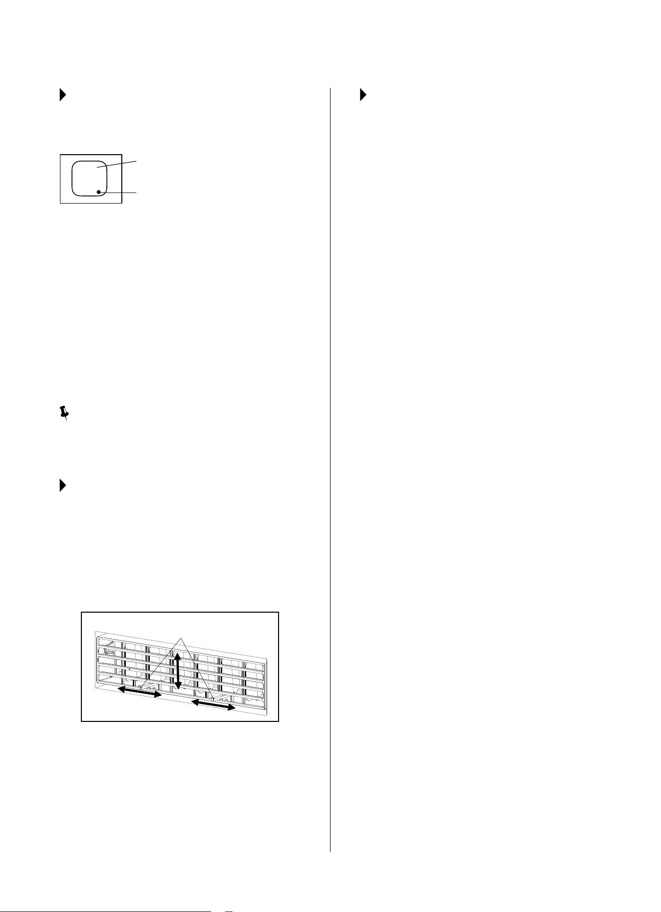
AIR DIRECTIONAL LOUVERS:
Usethe4-waydirectionallouverstodirecttheairow
up or down and left or right throughout the room as
needed.Pivothorizontallouversuntilthedesiredup/
down direction is obtained.
Move the center handles from side to side until the
desiredLeft/Rightdirectionisobtained.
There are a total of 4 possible air directional
orientations available with this system
Center Handles
ADDITIONAL THINGS YOU
SHOULD KNOW:
● TheCoolcircuithasanautomatic3minute
time-delayedstartiftheunitisturnedoandon
quickly.Afterunitisturnedo,leavetheunito
for a minimum of 3 minutes before attempting to
turnbackon.Thispreventsoverheatingofthe
compressorandpossiblecircuitbreakertripping.
The fan will continue to run during this time.
● Thecontroliscapableofdisplayingtemperaturein
degrees Fahrenheit or degrees Celsius. To convert
from one to the other, press and hold the left and
right TEMP/TIMERbuttons(
and
)atthe
same time for 3 seconds.
Display
Evaporator Temperature Sensor Error
21
CARE AND CLEANING
CAUTION
Cleanairconditioneroccasionallytokeepitlookingandoperatinglikenew.
Be sure to unplug the unit before cleaning to prevent shock or fire hazards.
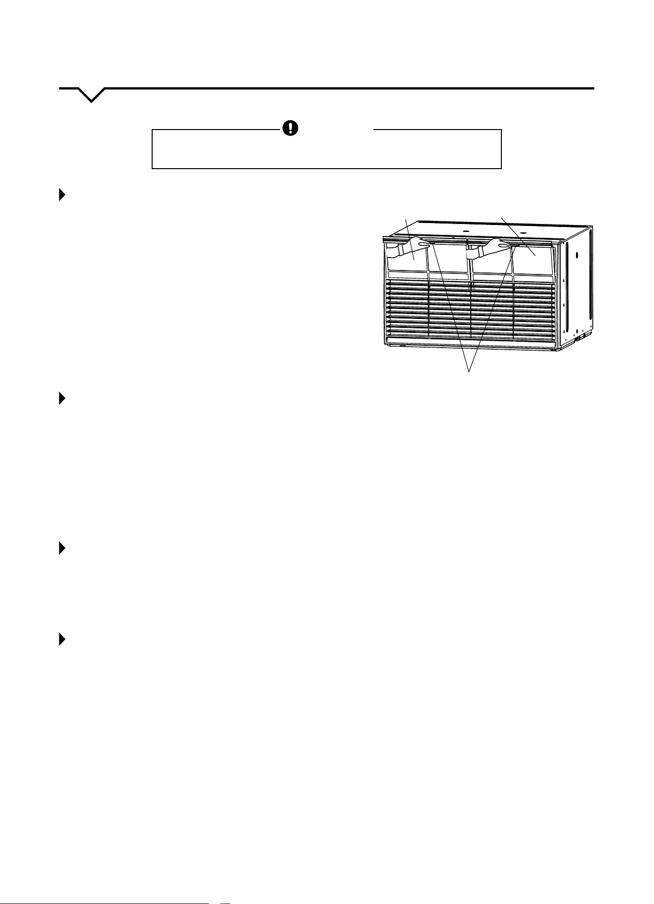
AIR FILTER CLEANING
Theairltershouldbecleanedatleasteverytwoweeksoras
necessary.Trappedparticlesintheltercanbuildupandcause
an accumulation of frost on the cooling coils.
● Therearetwoltersonthefrontoftheunit(LeftandRight).
Graspeachlterbythecenterandpullupandout.
● Washtheltersusingliquiddishwashingdetergentandwarm
water.Rinseltersthoroughly.
● Gentlyshakeexcesswaterfromthelters.Besurethelters
are thoroughly dry before replacing.
● Asanalternativetowashingthelters,vacuumthelterclean.
NOTE: Neverusehotwaterover104°F(40°C)tocleantheairfilter.
Never attempt to operate the unit without the air filter.
CABINET CLEANING
● Besuretounplugtheairconditionertopreventshockorre
hazard.Thecabinetandfrontmaybedustedwithanoil-free
cloth or with a cloth dampened in a solution of warm water
andmildliquiddishwashingdetergent.Rinsethoroughlyand
wipe dry.
● Neveruseharshcleaners,waxorpolishonthecabinetfront.
● Besuretowringexcesswaterfromtheclothbeforewipingthe
controls. Excess water in or around the controls may cause
damage to the air conditioner.
● Pluginairconditionerafterunithasdriedcompletely.
WINTER STORAGE
If air conditioner will be stored during the winter, remove it
carefully from the wall according to the installation instructions.
Cover it with plastic or return it to the original carton.
ALWAYS STORE UNIT IN UPRIGHT POSITION.
ENERGY SAVING NOTE
In order to reach maximum energy savings and comfort, when
not in use, it is recommended that the unit be covered inside your
homeforaddedinsulatingpurposes.Therecommendedsizefor
the cover is 24.4ʺ wide x 14.8ʺ high x 2.2ʺ deep.
Left filter
Right filter
Tab

22
NOTE
Ahighlyrecommendedtroubleshootforanyissueingeneralconsistsofturningounitandunpluggingfor5
minutes. It is also recommended to try another wall outlet. For further assistance, contact Consumer Services at
844-472-2473.
TROUBLESHOOTING
BEFORE CALLING FOR SERVICE, PLEASE REVIEW THE CHART BELOW
ISSUE POSSIBLE CAUSES
AIR CONDITIONER NOT
COOLING ROOM, OR NOT BLOWING
COLD AIR
•Besureunitisnottoolargeortoosmallfortheareaoftheroom.
•Verifythatalldoors,windows,curtainsandanyotheropeningsareclosed.
Verify nothing is obstructing the front grille of unit, such as curtains, etc.
•Allowenoughtimeforroomtocool,especiallyifoutsidetempisveryhigh.
•Checkthatthelterisnotdirtyandlouversareopenallthewayandblowinginthe
desired direction.
•CheckthatunitissettoCOOLmodeandthattemperatureisdownenough(but
nottoolow).
•Ifunitisnearaheatsource,suchasastove,etc.,thenrelocateunit.
•Ifaircomingfromunitiscooltothetouch,thenunitisworkingproperly;please
doublechecktherstthreebulletpointsabove.
•IfusingFollowMeremotefeature,moveremoteawayfromunit.
•Temperaturesensorbehindairltertouchingcoldcoil.Thesetwoelementsshould
not be touching. Carefully straighten tube away from coil.
•Unplugunitforatleast5minutes.FollowResetinstructionsonplug.
AIR CONDITIONER COOLING
BUT ROOM IS TOO WARM - ICE
FORMING ON COOLING COIL
BEHIND DECORATIVE FRONT
•Outdoortemperatureisbelow64ºF(18ºC).Todefrostthecoil,settoFAN
only mode.
•Airltermaybedirty.Cleanlter.RefertoCareandCleaningsection.Todefrost,
set to FAN only mode.
•Thermostatissettoocoldfornight-timecooling.Todefrostthecoil,settoFAN
only mode. Then, set temperature to a higher setting.
AIR CONDITIONER CYCLING ON
AND OFF TOO FREQUENTLY OR
NOT ENOUGH
•Besureunitisnottoolargeortoosmallfortheareaoftheroom.
•Removegrilleandmakesurethetemperaturesensorisnottooclosetothecoils.
These two elements should not be touching. Carefully straighten tube away
from coil.
•Makesurenothingisblockingthegrilleorsidevents.
•Makesurethereisnodirtordebrisinsidetheunitoronthelter.
UNIT WILL NOT TURN ON
•Resetcircuitbreaker.Makesuretherearenottoomanyitems(i.e.lamps,TV’s,
etc.)workingothesamebreaker.
•Checkplugconnection.
•Ifplugisoperatingonanon/oswitch,besurethattheswitchis‘on’.
•Trypluggingunitintoanotheroutlet.
•Unplugunitforatleast5minutes.FollowResetinstructionsonplug.
UNIT BLOWS FUSES OR POPS
CIRCUIT BREAKER
•Makesurethereareenoughavailableampsonthecircuitfortheairconditioner.
•Largeunitswhichrunona230vwillrequireadedicated20or30ampcircuit.
AIR CONDITIONER IS
MAKING NOISES
•Checktobesuretheunitisfreefromdebrissuchasleaves,sticks,etc.Verify
nothing is obstructing the unit.
•Checkthefanbladeforcracksorchips.
•Makesuretheunitisproperlyandsecurelymountedinsidethewindoworwall.
•Cleantheairlter.
WATER PUDDLES INSIDE UNIT OR IS
COMING INTO ROOM
•Adjusttheslopeoftheunitsothatitdrainsdownwardtowardtheexteriorofthe
home.(SeeInstallationInstructions.)
•Makesurethatthereisnodebrisblockingthedrainageareaoftheunit.
WATER DRIPPING OUTSIDE
•Unitisremovingalargequantityofmoisturefromahumidroom.Thisisnormal
during excessively humid days.
REMOTE SENSING / FOLLOW ME
DEACTIVATING PREMATURELY
•Remotecontrolnotlocatedwithinrange.Placeremotecontrolwithin20ftand
180ºradiusofthefrontoftheunit.
•Remotecontrolsignalobstructed.Removeobstruction.


The design and specifications are subject to change without prior notice for
product improvement. Consult with the sales agency or manufacturer for details.

Distributed by:
Perfect Aire, LLC
5401 Dansher Rd.
Countryside, IL 60525
844-4PA-AIRE | 844-472-2473
www.perfectaire.us
THRU-THE-WALL
AIR CONDITIONER
FOR MODELS:
4PATW8000
4PATW10000
4PATW10002
4PATW12000
4PATW12002
Before using your air conditioner, please
read this manual carefully and keep it for
future reference, along with your receipt.
Specification and performance data is subject to change without notice.
Printed in China
PA/User4PATW_ES/12132017
USER MANUAL