The 2N TELEKOMUNIKACE a.s. is a Czech manufacturer and supplier of
telecommunications equipment.
The product family developed by 2N TELEKOMUNIKACE a.s. includes GSM gateways,
private branch exchanges (PBX), and door and lift communicators. 2N
TELEKOMUNIKACE a.s. has been ranked among the Czech top companies for years
and represented a symbol of stability and prosperity on the telecommunications
market for almost two decades. At present, we export our products into over 120
countries worldwide and have exclusive distributors on all continents.
2N is a registered trademark of 2N TELEKOMUNIKACE a.s. Any product and/or other
®
names mentioned herein are registered trademarks and/or trademarks or brands
protected by law.
2N TELEKOMUNIKACE a.s. administers the FAQ database to help you quickly find
information and to answer your questions about 2N products and services. On www.
faq.2n.cz you can find information regarding products adjustment and instructions for
optimum use and procedures „What to do if...".
2N TELEKOMUNIKACE a.s. hereby declares that the 2N product complies with all
basic requirements and other relevant provisions of the 1999/5/EC directive. For the
full wording of the Declaration of Conformity see the CD-ROM (if enclosed) or our
website at www.2n.cz.
The 2N TELEKOMUNIKACE a.s. is the holder of the ISO 9001:2009 certificate. All
development, production and distribution processes of the company are managed by
this standard and guarantee a high quality, technical level and professional aspect of
all our products.

2N TELEKOMUNIKACE a.s., www.2n.cz 3/134
Content:
1. Product Description
1.1 Product Description
1.2 Differences between Models and Associated Products
1.3 Terms and Symbols Used
1.4 Safety Precautions
2. Description and Installation
2.1 Before You Start
2.2 Brief Installation Guide
2.3 Installation Conditions
2.4 2N® Indoor Compact LAN Location via 2N® Network Scanner
2.5 IP Address Lookup
3. Configuration
3.1 Factory Reset
3.2 Software Configuration
4. Device Control via Display
4.1 Directory
4.2 Call Log
4.3 Do Not Disturb Mode
4.4 Settings
5. Operational Statuses
6. Technical Parameters
7. Supplementary Information
7.1 Troubleshooting
7.2 Directives, Laws and Regulations - General Instructions and Cautions

2N TELEKOMUNIKACE a.s., www.2n.cz 4/134
1. Product Description
In this section, we introduce the product, outline its application 2N Indoor Compact
®
options and highlight the advantages following from its use. The section also includes
safety precautions.
1.1 Product Description
1.2 Differences between Models and Associated Products
1.3 Terms and Symbols Used
1.4 Safety Precautions

2N TELEKOMUNIKACE a.s., www.2n.cz 5/134
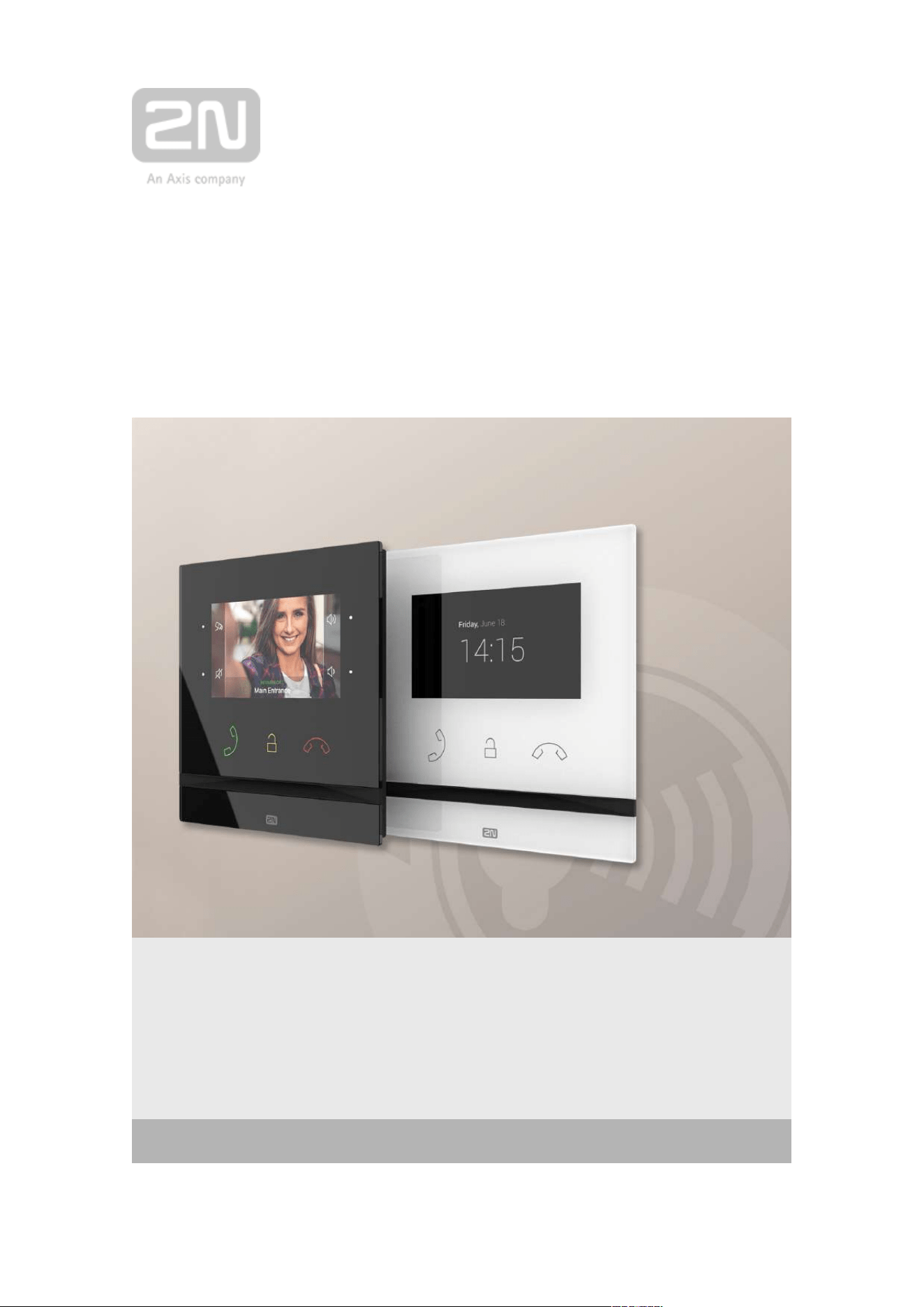
1.1 Product Description
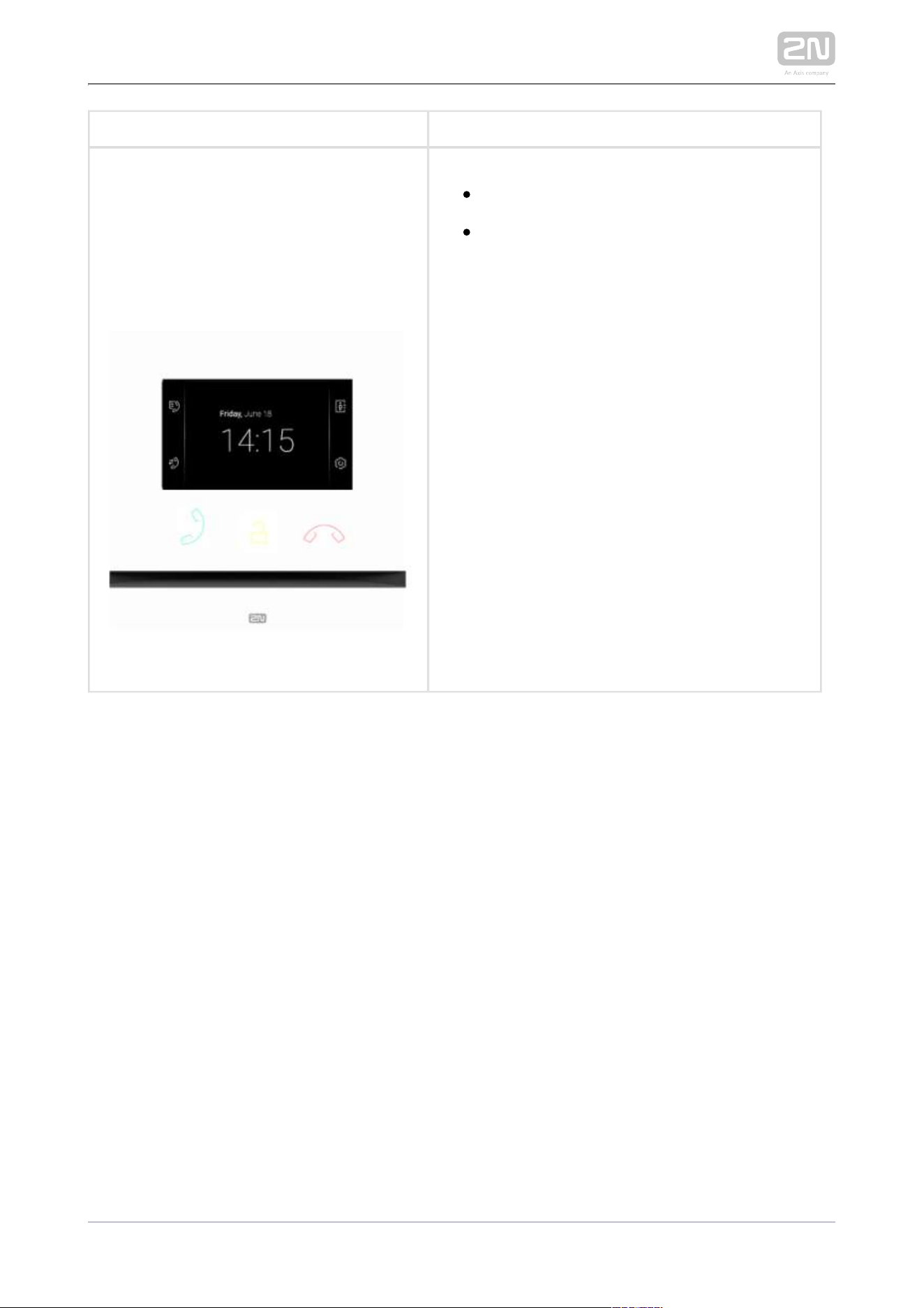
2N Indoor Compact
®
is a stylish, compact-design indoor IP/SIP unit providing audio
and video communication with the . The device includes a 4 mm 2N IP intercoms
enhanced glass touchscreen panel, Speakerphone, high-quality microphone with
excellent audibility and intelligibility properties, Ethernet LAN interface and induction
loop and doorbell external supply connectors. is a top-quality, 2N Indoor Compact
®
cost efficient and easy to install and configure answering unit. One installation can
combine variable answering units manufactured by 2N Telekomunikace a.s.
2N Indoor Compact
®
is equipped with a specific user interface for an increased user
comfort and safety.
Basic Features :2N Indoor Compact
®
4,3´´ color LCD video display
full duplex handsfree HD audio communication
LAN interface with PoE supply option
easy flush mounting
combination with and answering units2N Indoor Touch
®
2N Indoor Talk
®
remote administration and configuration via 2N Remote Configuration
®
call setup option via on a smartphone2N Mobile Video
®
DND mode and parental lock
remote door lock control
time display at relax
light signaling of activation by call
integrated user web interface
external doorbell button input
external power supply input
induction loop output
2N TELEKOMUNIKACE a.s., www.2n.cz 6/134
1.2 Differences between Models and
Associated Products
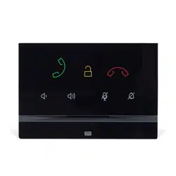
2N
®
Indoor Compact
2N Part No.
91378501
Axis Part No.
01935-001
2N Indoor Compact
®
– black
Indoor answering audio/video unit with
touch buttons designed for all 2N IP
intercoms
2N TELEKOMUNIKACE a.s., www.2n.cz 7/134
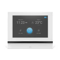
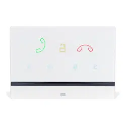
2N Part No.
91378501WH
Axis Part No.
01936-001
2N Indoor Compact
®
– white
Indoor answering audio/video unit with
touch buttons designed for all 2N IP
intercoms
2N TELEKOMUNIKACE a.s., www.2n.cz 8/134
Other Indoor Units and Accessories
Part Numbers:
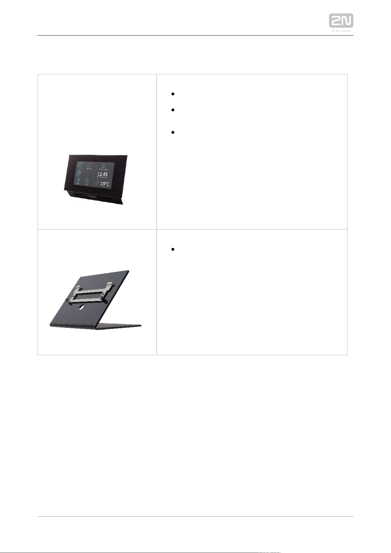
91378365
91378375
91378366
91378376
2N Indoor Touch
®
– black
WiFi version (third and fourth Part Nos.)
2N Indoor Touch
®
, an elegant indoor touch panel, is
designed for all of the . The display 2N IP intercoms
panel shows you the person standing at your door
and helps you make conversation with the visitor,
open the door lock or switch on the entrance hall
lights.
Part Number:
91378382
2N Indoor Touch
®
– desk stand black
2N TELEKOMUNIKACE a.s., www.2n.cz 9/134
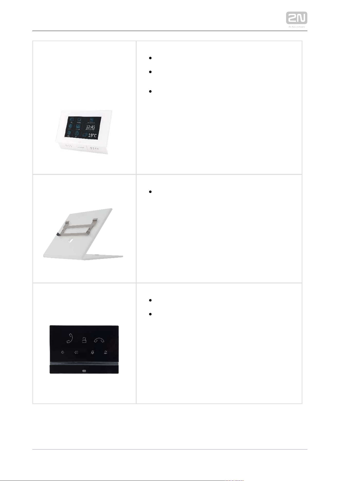
Part Numbers:
91378365WH
91378375WH
91378366WH
91378376WH
2N Indoor Touch
®
– white
WiFi version (third and fourth Part Nos.)
2N Indoor Touch
®
, an elegant indoor touch panel, is
designed for all of the . The display 2N IP intercoms
panel shows you the person standing at your door
and helps you make conversation with the visitor,
open the door lock or switch on the entrance hall
lights.
Part Number:
91378382W
2N Indoor Touch
®
– desk stand white
Part Number:
91378401
2N Indoor Talk
®
– black
Indoor answering audio unit with touchscreen
designed for all 2N IP intercoms
2N TELEKOMUNIKACE a.s., www.2n.cz 10/134
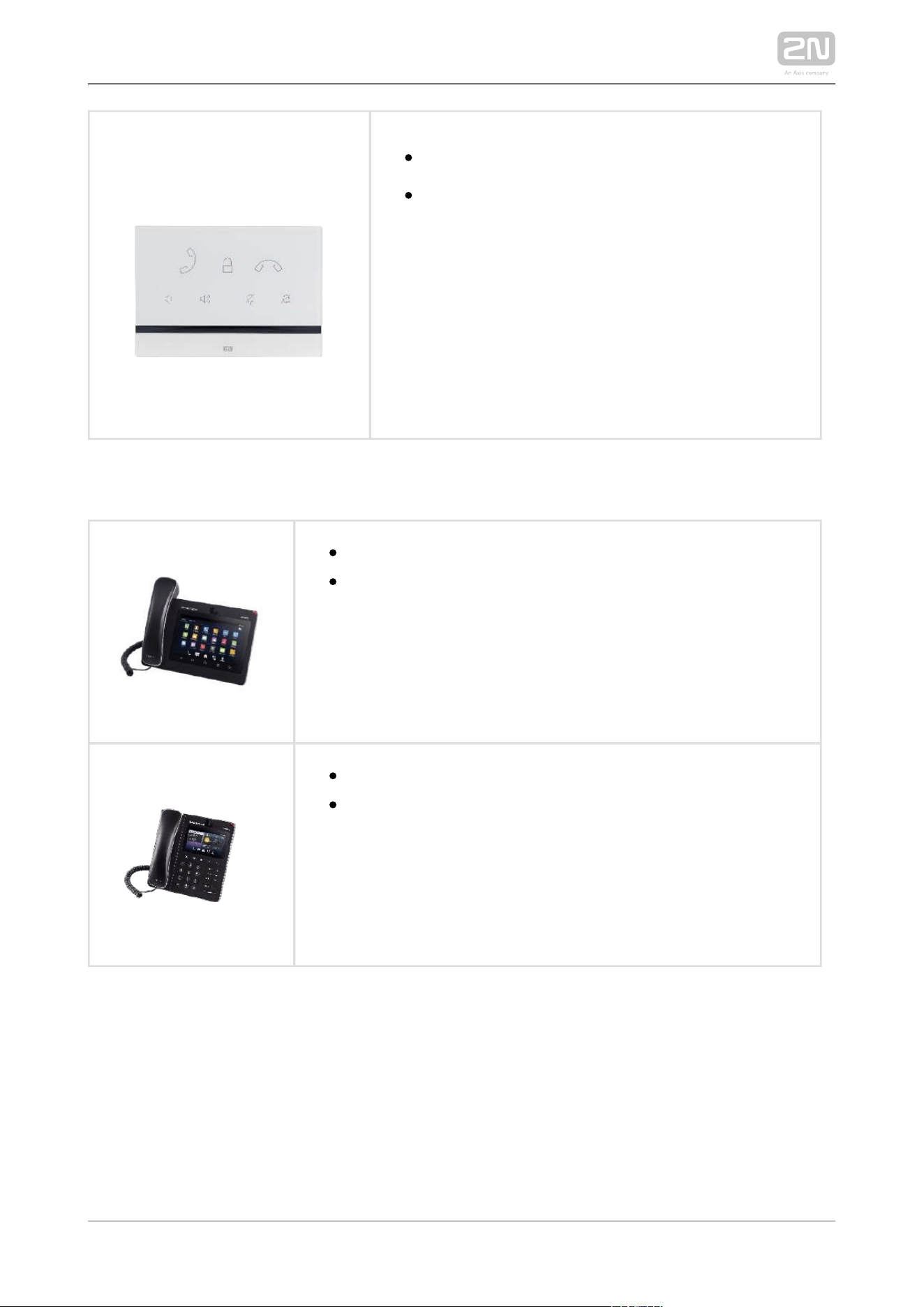
Part Number:
91378401WH
2N Indoor Talk
®
– white
Indoor answering audio unit with touchscreen
designed for all 2N IP intercoms
VoIP Phones
91378358Part No.
Grandstream GXV3240 VoIP video telephone
GXV3240 is the successor to the popular GXV3140 model,
which provides comfortable video calls in the IP network.
Touchscreen and keypad control.
91378357Part.No.
Grandstream GXV3275 VoIP video telephone
GXV3275 is the successor to the popular GXV3175 model,
which provides comfortable video calls in the IP network.
Touchscreen control.
2N TELEKOMUNIKACE a.s., www.2n.cz 11/134
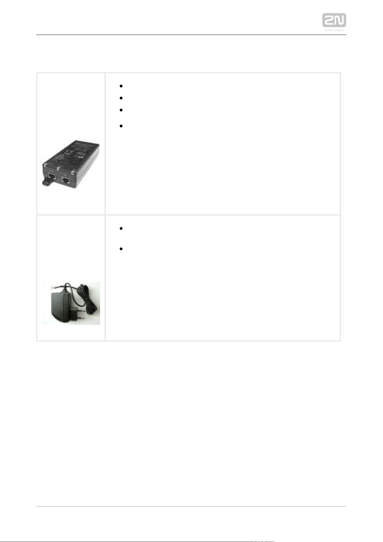
Power Supply
Part Numbers
91378100
91378100E
91378100US
PoE injector – without cable
PoE injector - with EU cable
PoE injector – with US cable
For Ethernet cable supply where PoE is unavailable.
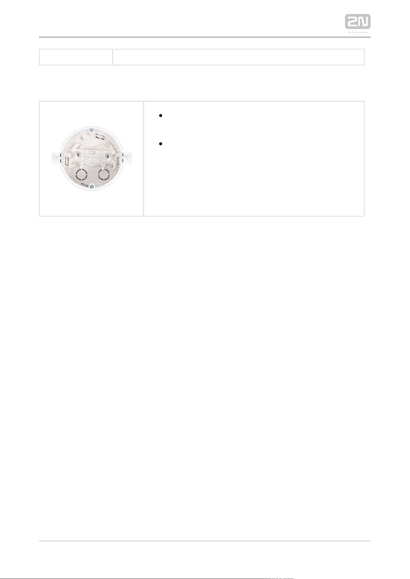
Part Numbers:
91378381E
91378381GB
91378381US
Stabilized 12 V / 2 A power supply needs to be used where no PoE
is available.
Part number according to the electric socket end piece (E/GB/US).
2N TELEKOMUNIKACE a.s., www.2n.cz 12/134
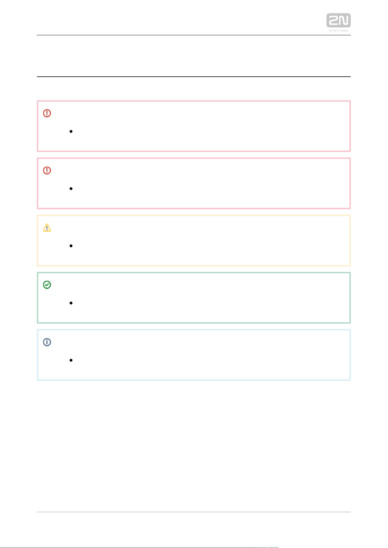
Mounting Accessories
91378800Part No.
Flush mounting box is for brick/plasterboard necessary
walls.
Not included in the package.2N Indoor Compact
®
2N TELEKOMUNIKACE a.s., www.2n.cz 13/134
1.3 Terms and Symbols Used
The following symbols and pictograms are used in the manual:
Safety
Always abide by this information to prevent persons from injury.
Warning
Always abide by this information to prevent damage to the device.
Caution
Important information for system functionality.
Tip
Useful information for quick and efficient functionality.
Note
Routines or advice for efficient use of the device.
2N TELEKOMUNIKACE a.s., www.2n.cz 14/134
1.4 Safety Precautions
The manufacturer reserves the right to modify the product in order to improve its
qualities. The manufacturer continuously responds to the clients' requirements by
improving the software. Refer to the company websites for the latest www.2n.cz 2N
®
firmware and User Manual.Indoor Compact
Where necessary, the device can be installed at a safe distance from the
prohibited area and an Ethernet cable can only be carried to the required site.
Install out of reach of sensitive devices and human bodies 2N Indoor Compact
®
as it emits electromagnetic interference.
Refer to S. for the range of operating temperatures.6.Technical Parameters
The device may not be operated at places exposed to direct sunlight or near
heat sources.
2N Indoor Compact
®
is designed for indoor use. It may not be exposed to rain,
flowing water, condensing moisture, fog, and so on.
It may not be exposed to aggressive gases, acid and solvent vapors, etc.
It is designed for LAN connection.
Caution
This product and its installation and configuration techniques are not
intended for persons with diminished physical, sensory or mental
capacities or persons with limited experience and knowledge unless
expertly supervised or duly advised as to the use of this product by a
person responsible for their safety.

2N TELEKOMUNIKACE a.s., www.2n.cz 15/134
2. Description and Installation
This section describes how to install and connect properly.2N Indoor Compact
®
Here is what you can find in this section:
2.1 Before You Start
2.2 Brief Installation Guide
2.3 Installation Conditions
2.4 2N® Indoor Compact LAN Location via 2N® Network Scanner
2.5 IP Address Lookup

2N TELEKOMUNIKACE a.s., www.2n.cz 16/134
2.1 Before You Start
Package Completeness Check
Please check the product delivery before starting installation: Contents:
1
2N Indoor Compact
®
1 Certificate of ownership
1 2.5 mm hexagon key wrench
1 Quick Start manual
1 display cleaning cloth
2N TELEKOMUNIKACE a.s., www.2n.cz 17/134
1.
2.
3.
4.
5.
6.
7.
8.
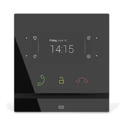
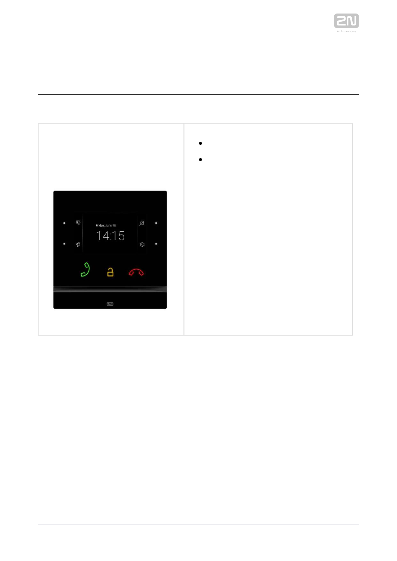
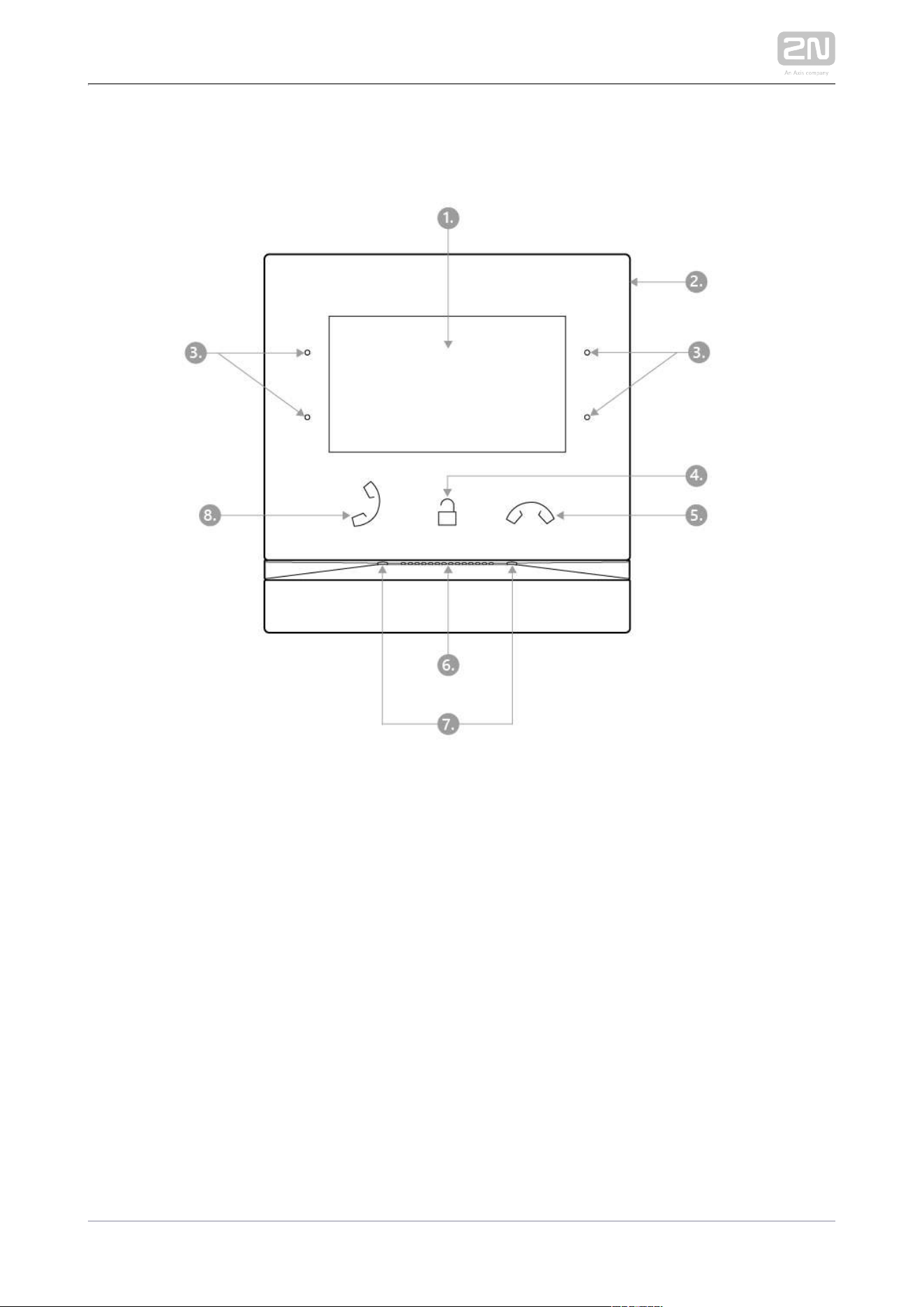
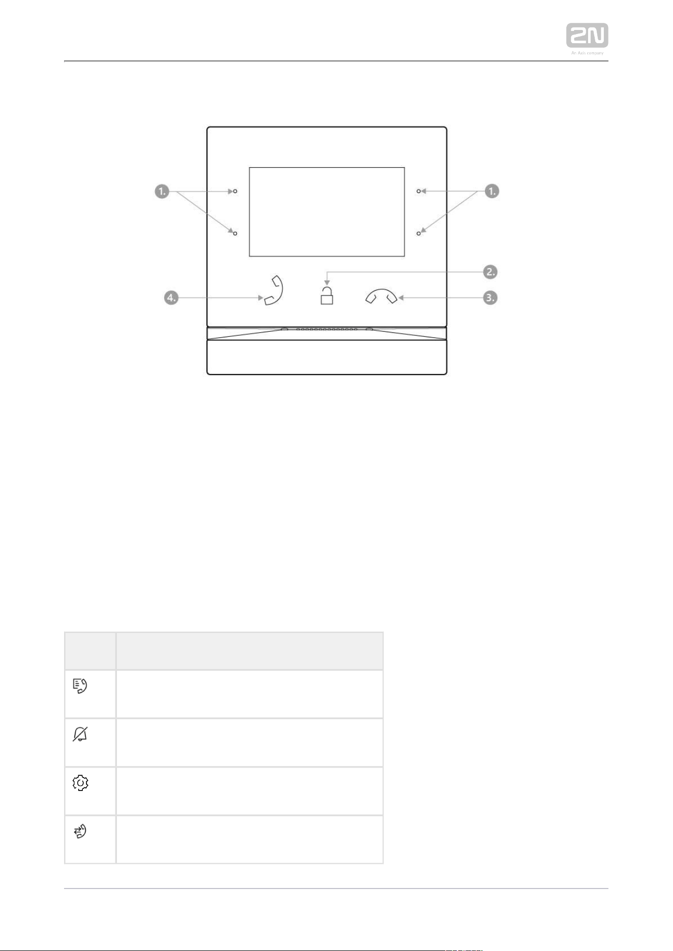
Front Layout
Display
Microphone
MENU buttons
Lock button
Call end button
Speaker
Anchoring holes
Call answering button
2N TELEKOMUNIKACE a.s., www.2n.cz 18/134
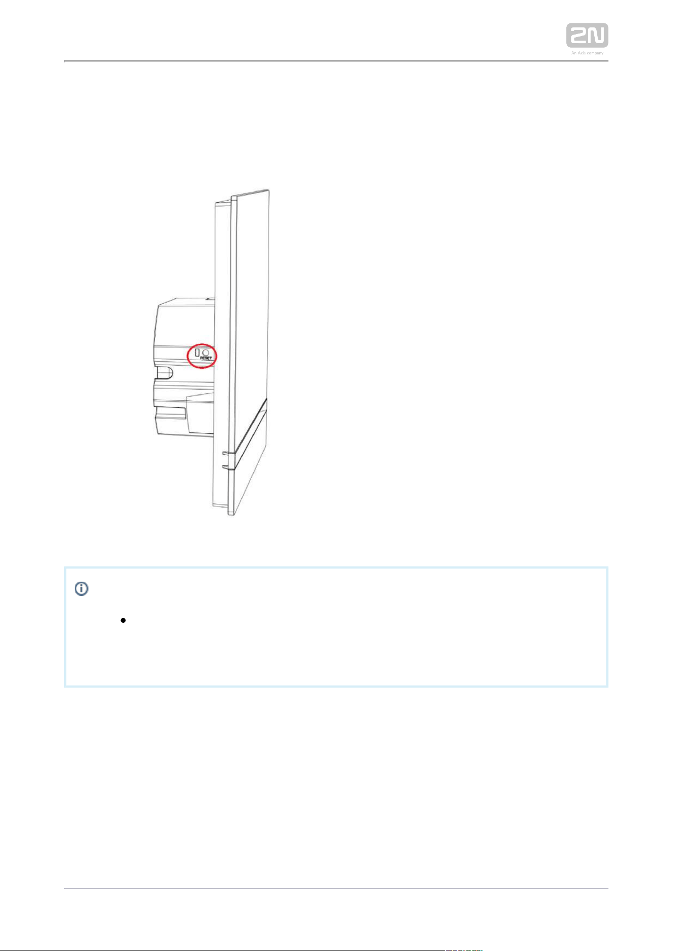
1.
2.
3.
4.
5.
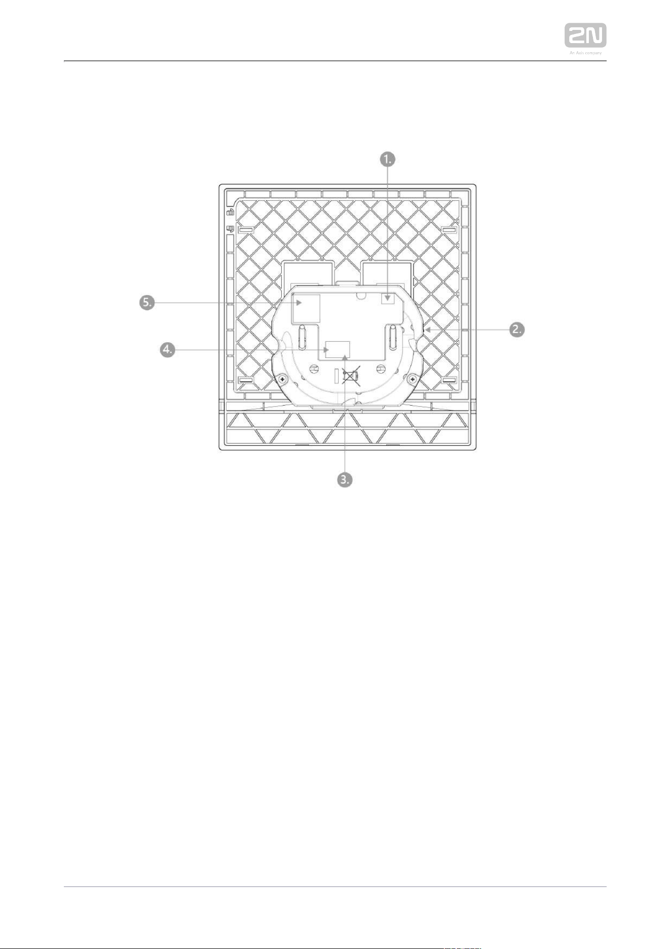
Backside Connectors
External induction loop output
Reset button
Doorbell button input
12 V / 1 A DC power supply input
Ethernet
2N Indoor Compact
®
is designed exclusively for flush mounting (brick and
plasterboard walls). Use the flush mounting box (Part No. 2N Indoor Compact
®
91378800),which is not part of the delivery.
2N TELEKOMUNIKACE a.s., www.2n.cz 19/134
2N TELEKOMUNIKACE a.s., www.2n.cz 20/134
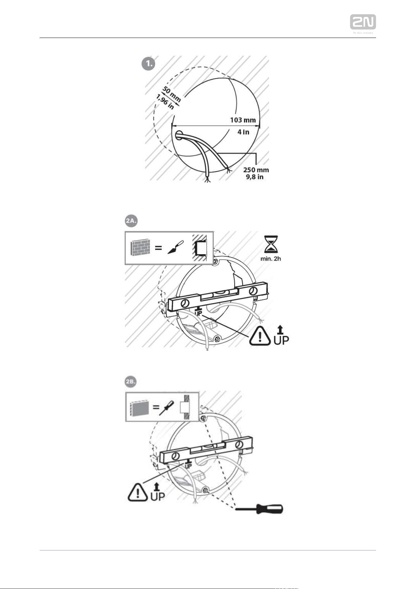
Cut a circular hole in the wall of the diameter of 103 mm and depth of 50 mm before
installation. It is assumed that all necessary cables of the maximum length of 25 cm
will lead to the hole. Put the flush mounting box in the hole to make sure that the hole
is deep enough. If the hole complies with the box size, wall in the box and level the
box using a water level on the holding clips. When the mortar hardens, break off the
Use anchoring elements to fix the clips and cap the box with the cover provided.
device into plasterboard.
Downloads
Drilling template.pdf
Use a 2.5 mm hexagon key wrench (included in the delivery) for 2N Indoor Compact
®
fitting into the flush mounting box.2N Indoor Compact
®
Note
While flush mounting respect the local standards 2N Indoor Compact
®
concerning installation of electronic devices on flammable materials.
2N TELEKOMUNIKACE a.s., www.2n.cz 21/134
2.2 Brief Installation Guide
2N TELEKOMUNIKACE a.s., www.2n.cz 22/134
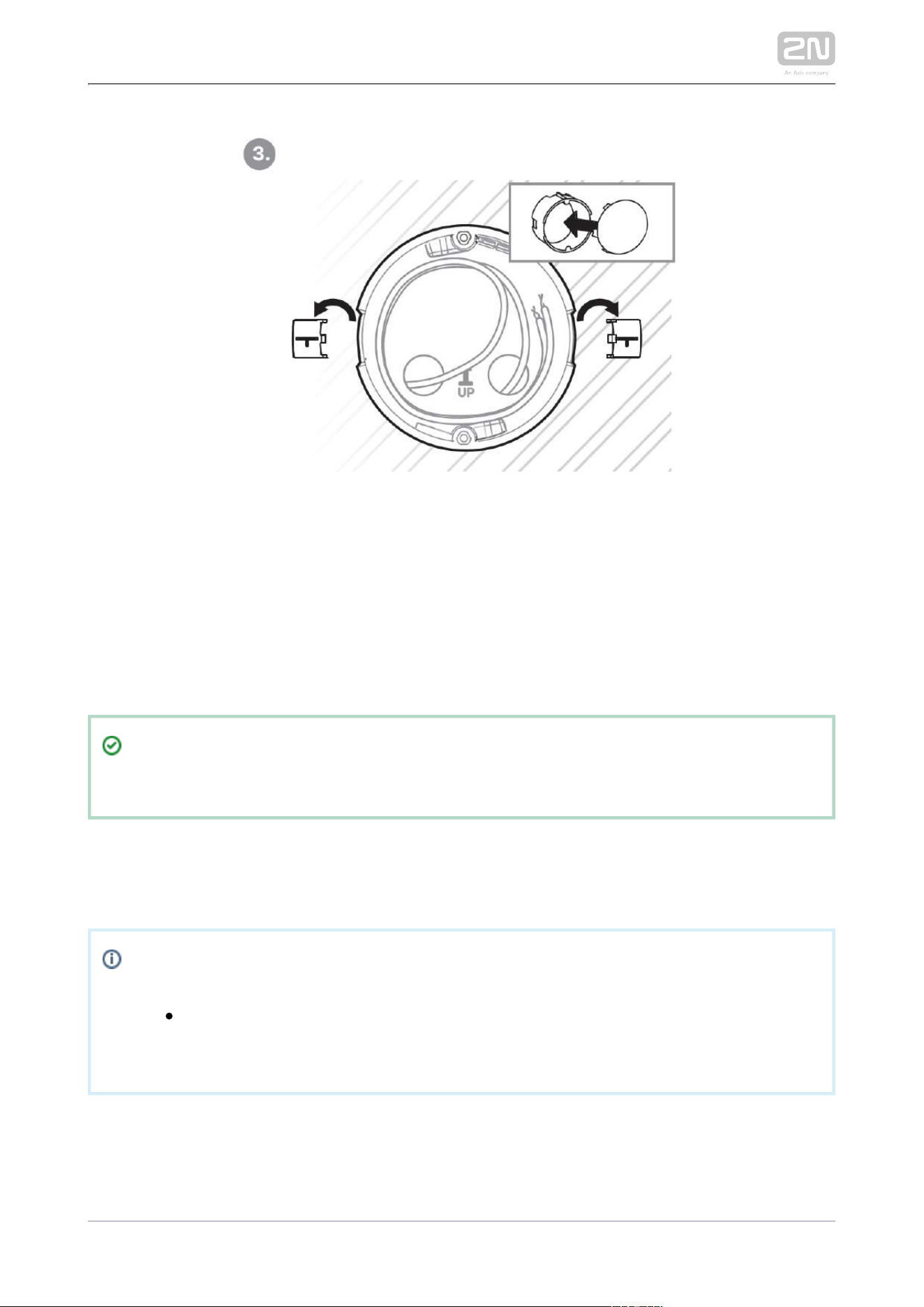
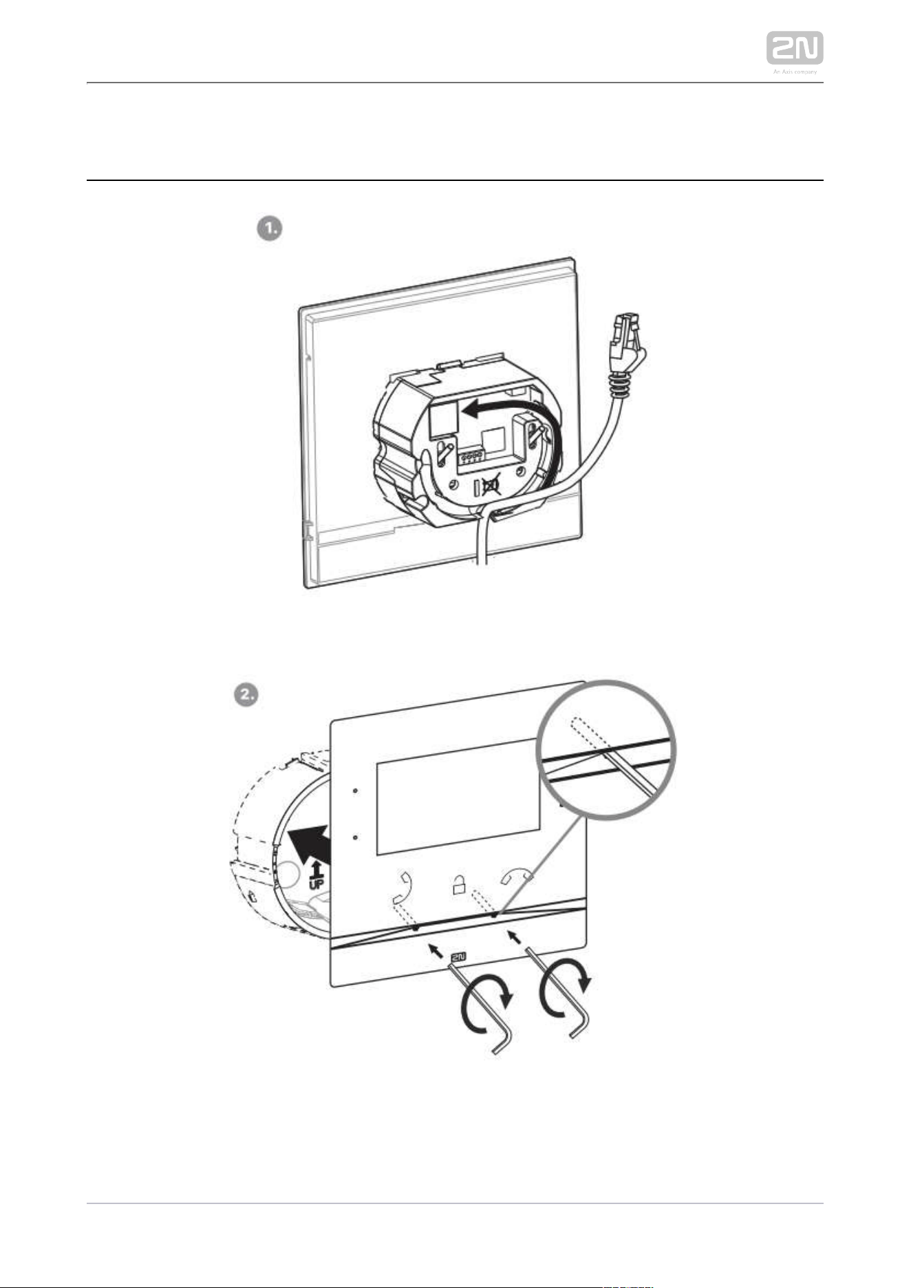
Remove the cover from the walled-in flush mounting box. 2N Indoor Compact
®
Remove the pre-prepared cabling, UTP cable, doorbell twin cable and power supply
cable. Shorten the cables to 150 mm or less as required. Connect the doorbell twin
cable or power supply cable to the connector provided. Crimp the RJ-45 connector
onto the UTP cable. Take and lean its bottom edge against the 2N Indoor Compact
®
wall below the flush mounting box. First plug the green power/doorbell connector.
Connect the LAN connector. Put the cables carefully in the pre-drilled 2N Indoor
®
back slot to prevent them from blocking any horizontal levelling movement Compact
during the final installation stage. Insert in the flush mounting 2N Indoor Compact
®
box making sure that it clicks onto the levelling pins, which allow for a 5–6 ° inclination
. Apply the box screw nuts with the on either side for accurate horizontal levelling
hexagon key wrench provided. Level with a water level and 2N Indoor Compact
®
tighten the screws gently. Now is ready for basic operation.2N Indoor Compact
®
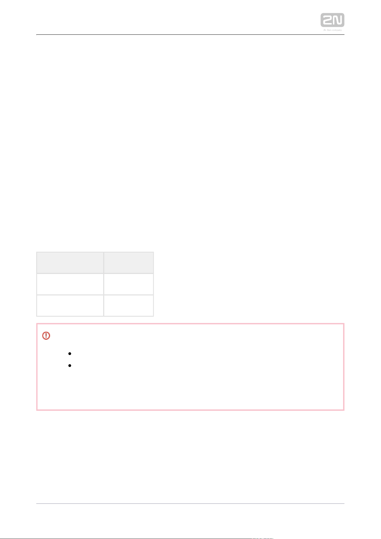
2N Indoor Compact
®
consumption with variable power supplies:
Supply type Consumption
PoE, IEEE 802.3af 12 W
12 V / 1 A 12 W
Warning
Do not connect any external power supply if PoE is used and vice versa.
If you use a power adapter other than the recommended one, do not
exceed the 12 V rated supply voltage. Also check the supply voltage
polarity. Higher voltage values or misconnections may result in an
irreplaceable device damage.

2N TELEKOMUNIKACE a.s., www.2n.cz 23/134
1.
2.
2.3 Installation Conditions
Make sure that the following installation conditions are met: 2N Indoor Compact
®
There must be enough space for the device installation.
The device is designed for vertical wall mounting (perpendicular to the floor) in
the height of up to 120 cm above the floor. If necessary, operate the device in a
position other than as aforementioned for a short time only, for quick testing
purposes in a servicing center, for example.
Exceeding the allowed operating temperature may not affect the device
immediately but leads to premature ageing and lower reliability. For the
acceptable range of operating temperatures and relative humidity values refer
to .Technical Parameters
The device is not designed for environments with increased vibrations such as
means of transport, machine rooms and so on.
The device is not intended for dusty environments and places with unstable
humidity and abrupt temperature changes.
The device may not be exposed to aggressive gas, acid vapors, solvents, etc.
The device is not intended for direct connection into the Internet/WAN.
The device must be connected to the Internet/WAN via a separating active
network element (switch/router).
The device is designed for indoor use. It may not be exposed to rain, flowing
water, condensing moisture, fog, etc.
The device cannot be operated on places exposed to direct sunshine and near
heat sources.
Keep some free space above and below the device to allow air to flow and
conduct heat away.
No strong electromagnetic radiance is allowed on the installation site.
Make sure that the VoIP connection is configured properly according to the SIP
and other VoIP recommendations.
It is recommended that the power adapter be connected to the mains via a UPS
and reliable overvoltage protection.
Power Supply Connection
You can feed as follows:2N Indoor Compact
®
Use a 12 V / 2 A DC power adapter connected to the backside terminal board.
Use an Ethernet cable connected to a PoE supply or PoE supporting Ethernet
switch/router.
PoE Supply Connection
2N TELEKOMUNIKACE a.s., www.2n.cz 24/134
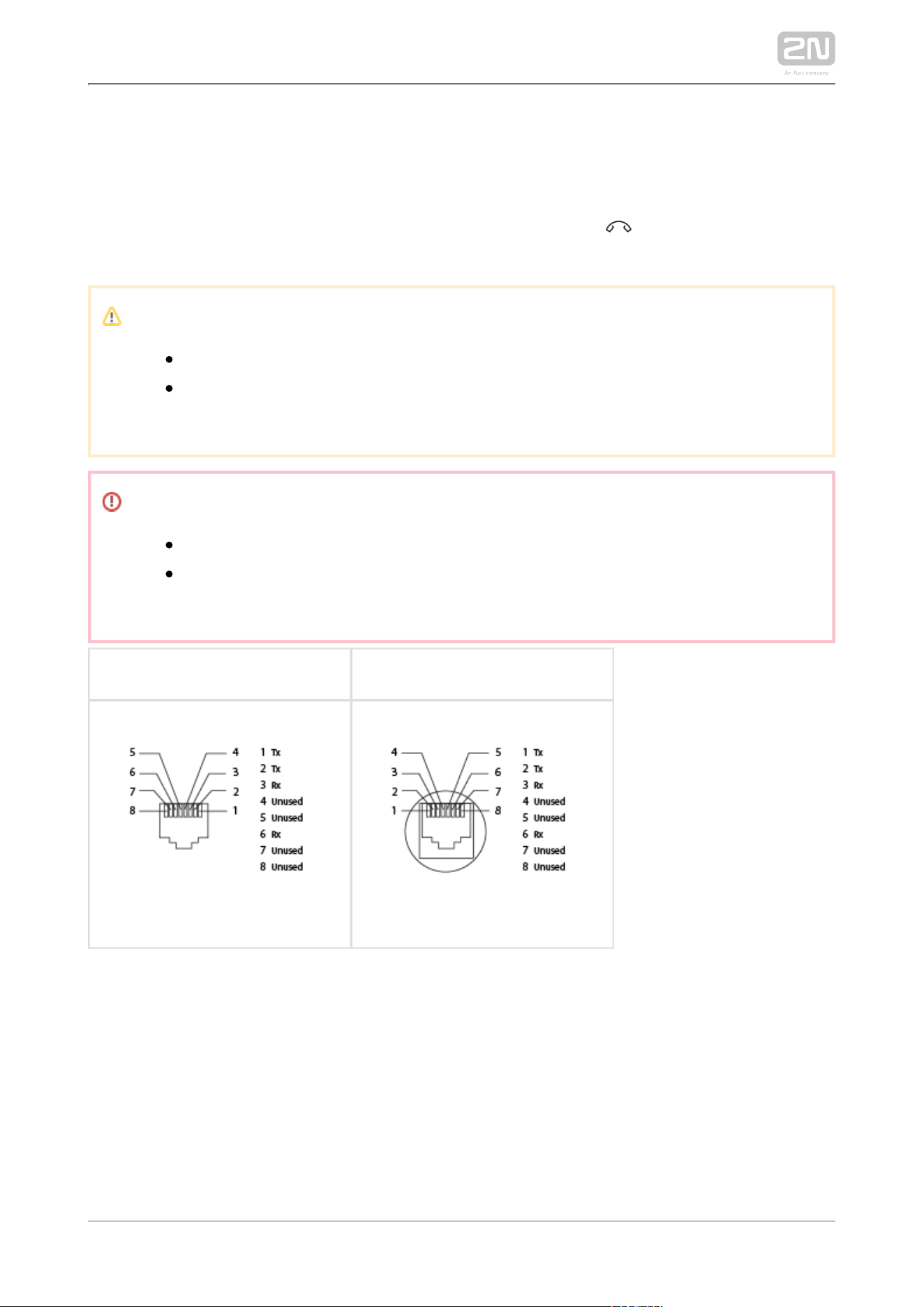
PoE Supply Connection
Use a standard straight RJ-45 terminated cable to connect to 2N Indoor Compact
®
the Ethernet. The device supports the 10BaseT and 100BaseT protocols. The Ethernet
connection state is indicated by a hung-up receiver symbol . If the symbol flashes,
the device is disconnected from the network.
Caution
Factory reset results in a change of the Ethernet interface configuration!
A defective Ethernet cable may lead to a high packet loss in the
Ethernet and subsequent instability and poor call quality!
Warning
Do not connect any external power supply if PoE is used and vice versa.
Connection of a defective or improper power supply may lead to a
temporary or permanent device failure.
Ethernet cable connector Ethernet socket
Firmware Upload
We recommend you to upgrade the firmware during installation. 2N Indoor Compact
®
Refer to for the latest FW version. Refer to for the firmware www.2n.cz 3.2.5 System
upgrade procedure.
2N TELEKOMUNIKACE a.s., www.2n.cz 25/134
1.
2.
3.
2.4 2N® Indoor Compact LAN Location via
2N® Network Scanner
2N Indoor Compact
®
is configured via the administration web server. Connect the
device to the LAN IP and make sure it is properly powered.
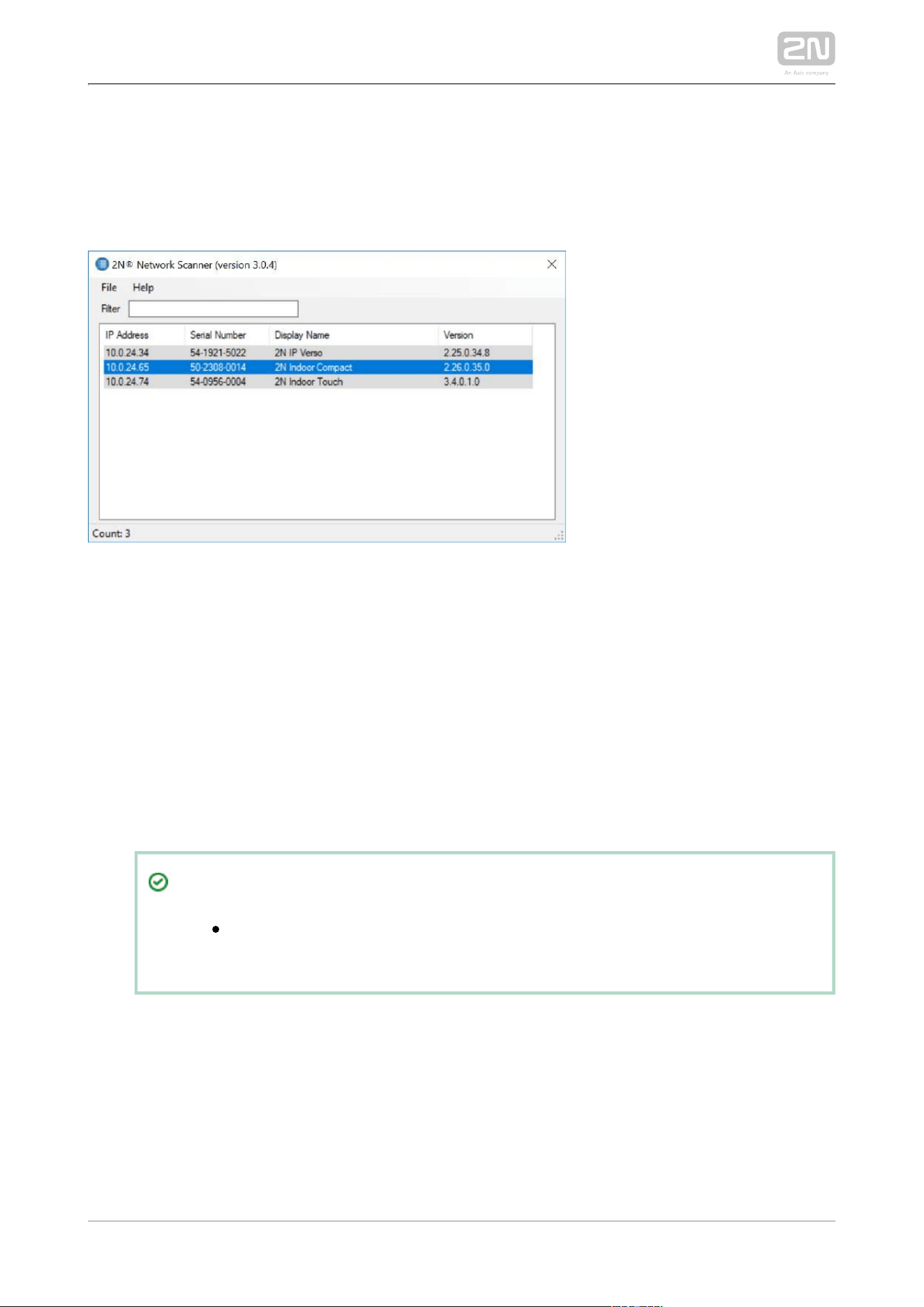
2N ® Network Scanner Description
The application helps find the IP addresses of all the devices in 2N
®
Indoor Compact
the LAN. Download the app from the 2N web sites ( ). Make sure that www.2n.cz
Microsoft .NET Framework 2.0 is installed for successful app installation.
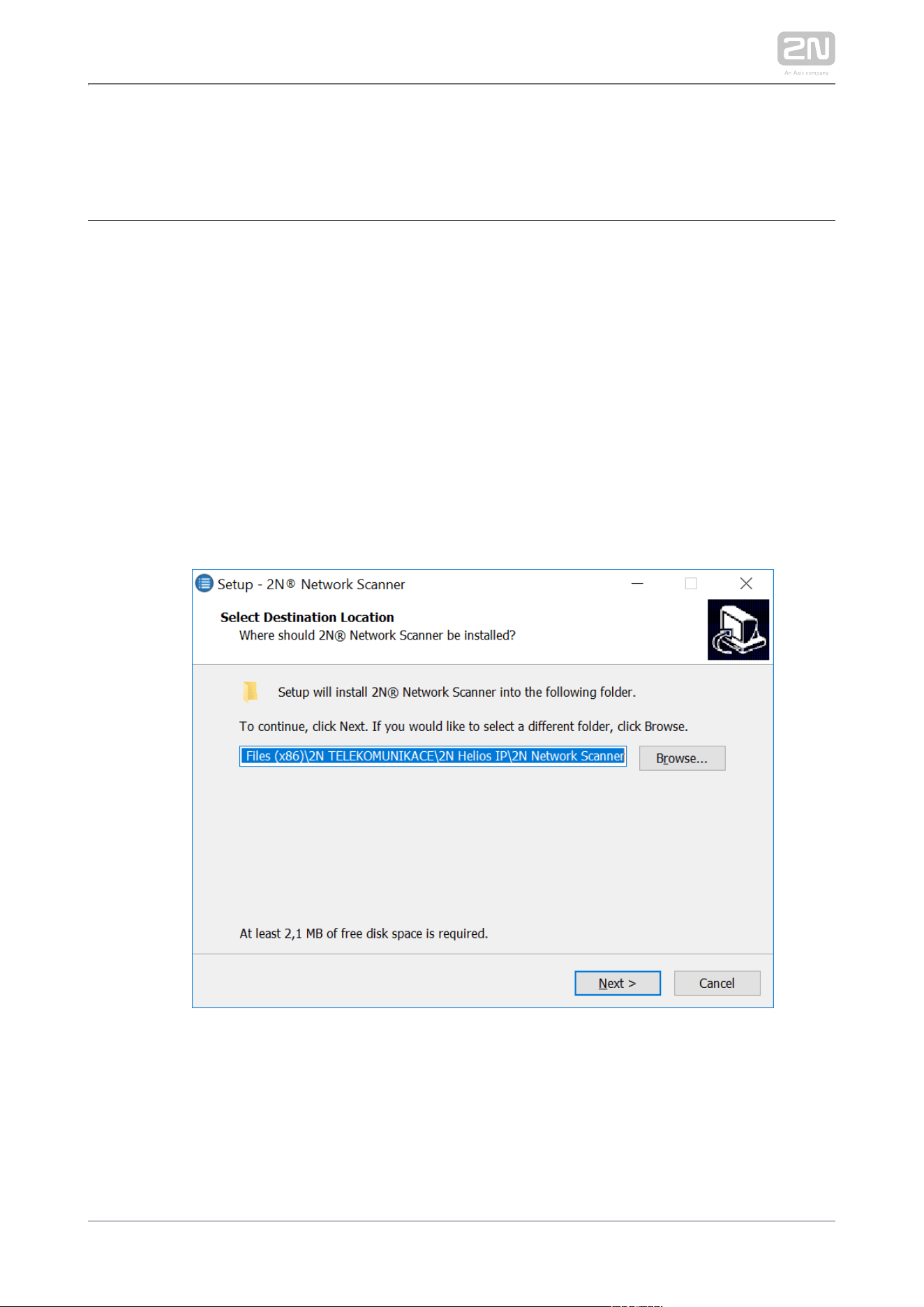
Run the .2N
®
Network Scanner
Use the Setup Wizard for successful installation.
2N
®
IP Network Scanner Installer
Having installed the , start the application using the 2N
®
IP Network Scanner
Microsoft Windows Start menu.
2N TELEKOMUNIKACE a.s., www.2n.cz 26/134
1.
Once started, the application begins to automatically search for all the 2N IP intercoms
in the LAN including their smart extensions ( , , 2N Indoor Compact
®
2N
®
Indoor Talk 2N
), which are DHCP/statically assigned IP addresses. All the devices are
®
Indoor Touch
displayed in a table.
2N
®
IP Network Scanner
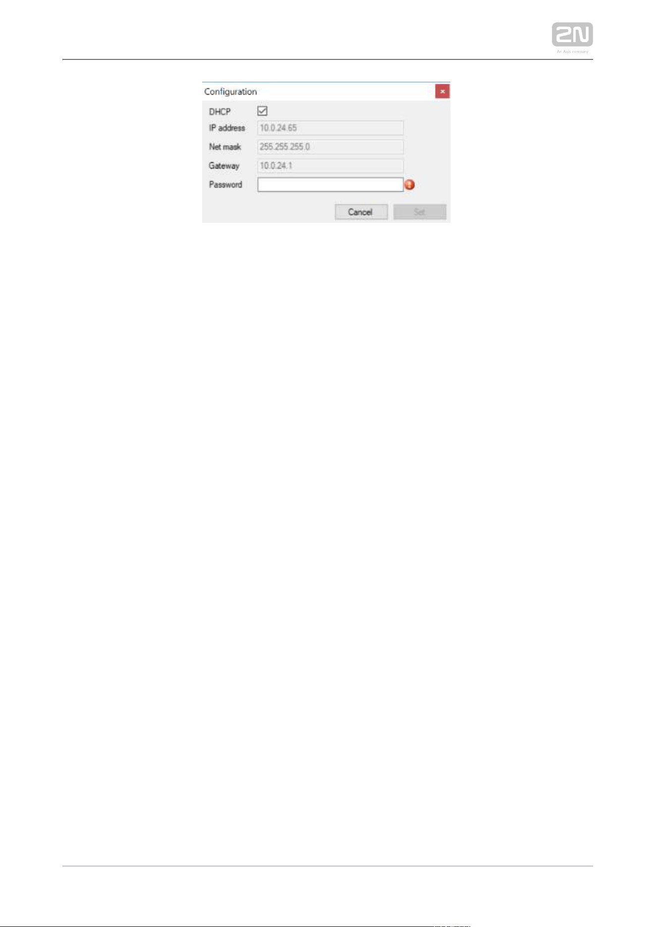
Select the device to be configured and right-click it. Select 2N
®
Indoor Compact
… to open the administration web interface login
Browse…
2N
®
Indoor Compact
window for configuration. To change the device IP address, select and
Config
enter the required static IP address or activate DHCP. The default configuration
password is 2n. If the found device is grey highlighted, its IP address cannot be
configured using this application. In that case, click Refresh to find the device
again and check whether multicast is enabled in your network.
Tip
Double click the selected row in the list to 2N
®
IP Network Scanner
access the device web interface easily.
2N TELEKOMUNIKACE a.s., www.2n.cz 27/134
2N
®
IP Network Scanner IP Address Change
2N TELEKOMUNIKACE a.s., www.2n.cz 28/134
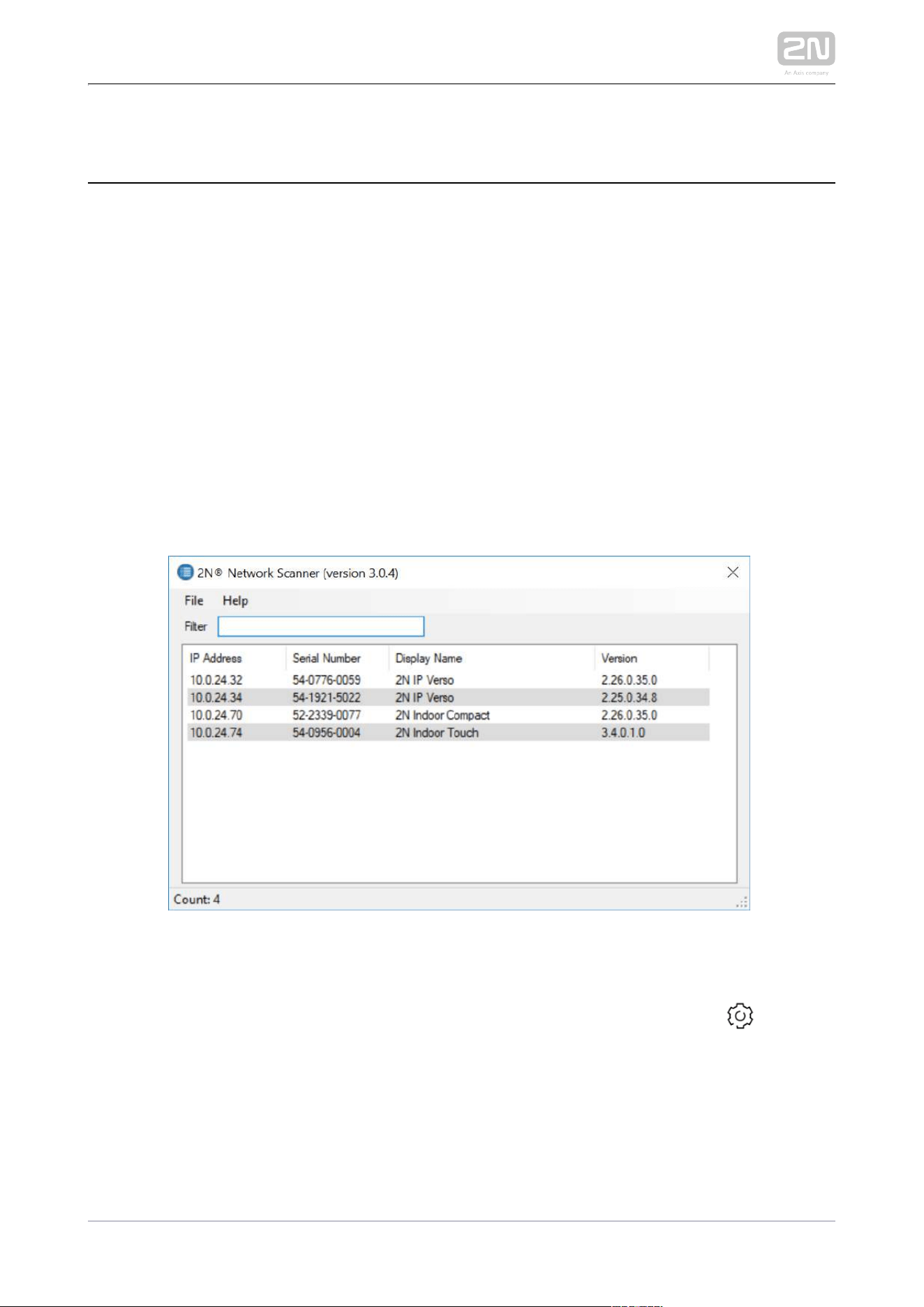
2.5 IP Address Lookup
To look up the device IP address, take the following steps: Use the free 2N Network
®
application or view the information on the device display.Scanner
To find the IP address via the , follow the 2N Indoor Compact
®
2N Network Scanner
®
steps mentioned in the previous subsection, 2.4 2N Indoor Compact LAN Location
®
. Once started, the application begins to automatically via 2N Network Scanner
®
search for all the in the LAN including their smart extensions (2N IP intercoms 2N
®
, , ), which are DHCP/statically Indoor Compact 2N
®
Indoor Talk 2N
®
Indoor Touch
assigned IP addresses. All the devices are displayed in a table including the IP
addresses assigned to them.
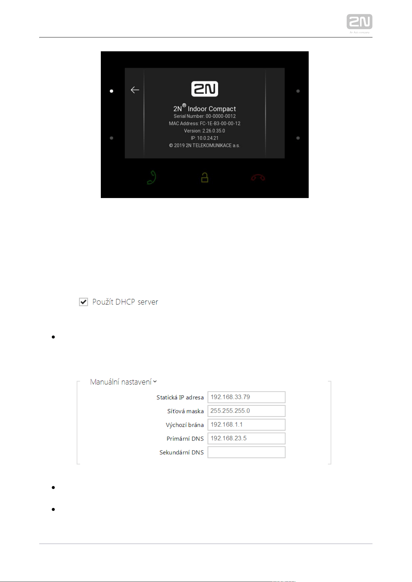
To find the IP address using the display, press any key on the 2N Indoor Compact
®
display to quit the sleep mode. Click the right-hand lower button at the icon on
the home screen to display the Settings menu. Find the IP address information in the
Settings / System / About device menu.
2N TELEKOMUNIKACE a.s., www.2n.cz 29/134
Dynamic/Static IP Address Switching
To be connected to the LAN properly, has to be assigned a valid 2N Indoor Compact
®
IP address or obtain the IP address from the LAN DCHP server. Configure the IP
address and DHCP in the System / Network menu.
Use DHCP server – enable automatic obtaining of the IP address from the LAN
DHCP server. If there is no DHCP server or the DHCP cannot be used in your
network, use the manual network setting.
Static IP address – static IP address of the device. The address is used together
with the parameters below unless Use DHCP server is enabled.
Network mask – set the network mask.

2N TELEKOMUNIKACE a.s., www.2n.cz 30/134
Default gateway – address of the default gateway, which provides
communication with off-LAN equipment.
Primary DNS – primary DNS address for domain name-to-IP address translation.
Secondary DNS – secondary DNS address where the primary DNS is unavailable.
2N TELEKOMUNIKACE a.s., www.2n.cz 31/134
3. Configuration
3.1 Factory Reset
3.2 Software Configuration
Login
Fill in the address or domain name into the internet browser to 2N
®
Indoor Compact
display the login screen. The default login user name and password are as follows:
Username: Admin
Password: 2n
Should the login screen fail to appear, you must have typed a wrong IP address/port
or the administration web server has been switched off. To find 2N Indoor Compact
®
the correct IP address, use the as described in 2N
®
Network Scanner 2.4 2N® Indoor
.Compact LAN Location via 2N Network Scanner
®
Language Selection
Use the menu in the right-hand upper corner of the web interface to select language.
Language Selection
2N TELEKOMUNIKACE a.s., www.2n.cz 32/134
3.1 Factory Reset
Reset Button
Located among the main unit connectors, the Reset button helps you reset the factory
default values, restart the device, find the device IP address and switch the static
/dynamic mode.
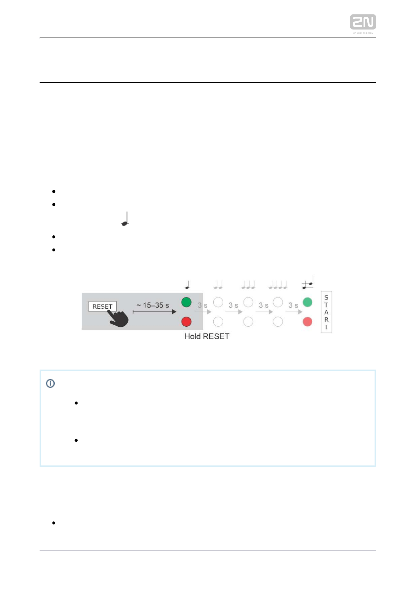
IP Address Finding
Follow the instructions below to :identify the current IP address
Press and hold the RESET button.
Wait until the red and green LEDs go on simultaneously on the device and the
acoustic signal can be heard (approx. 15–35 s).
Release the RESET button.
The device automatically announces the current IP address.
Note
The delay after pressing RESET till the first light and sound signalling is
set to 15–35 s depending on the 2N IP intercom/answering unit model
used.
15 s is the valid value for .2N Indoor Compact
®
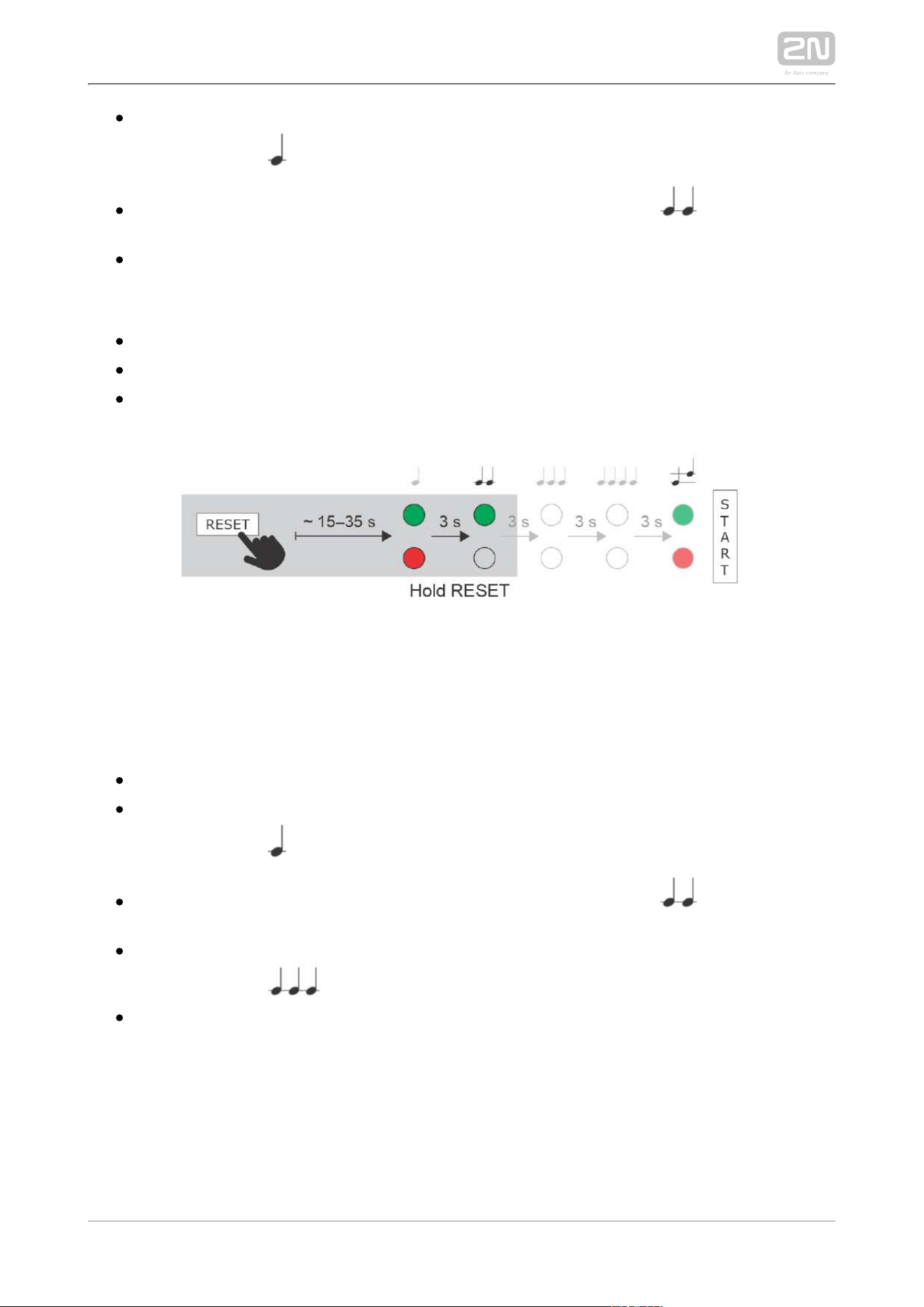
Static IP Address Setting
Follow the instructions below to switch on the mode (DHCP OFF):Static IP address
Press and hold the RESET button.
Wait until the red and green LEDs go on simultaneously on the device and the
2N TELEKOMUNIKACE a.s., www.2n.cz 33/134
Wait until the red and green LEDs go on simultaneously on the device and the
acoustic signal can be heard (approx. 15–35 s).
Wait until the red LED goes off and the acoustic signal can be heard
(approx. for another 3 s).
Release the RESET button.
The following network parameters will be set after restart:
IP address: 192.168.1.100
Network mask: 255.255.255.0
Default gateway: 192.168.1.1
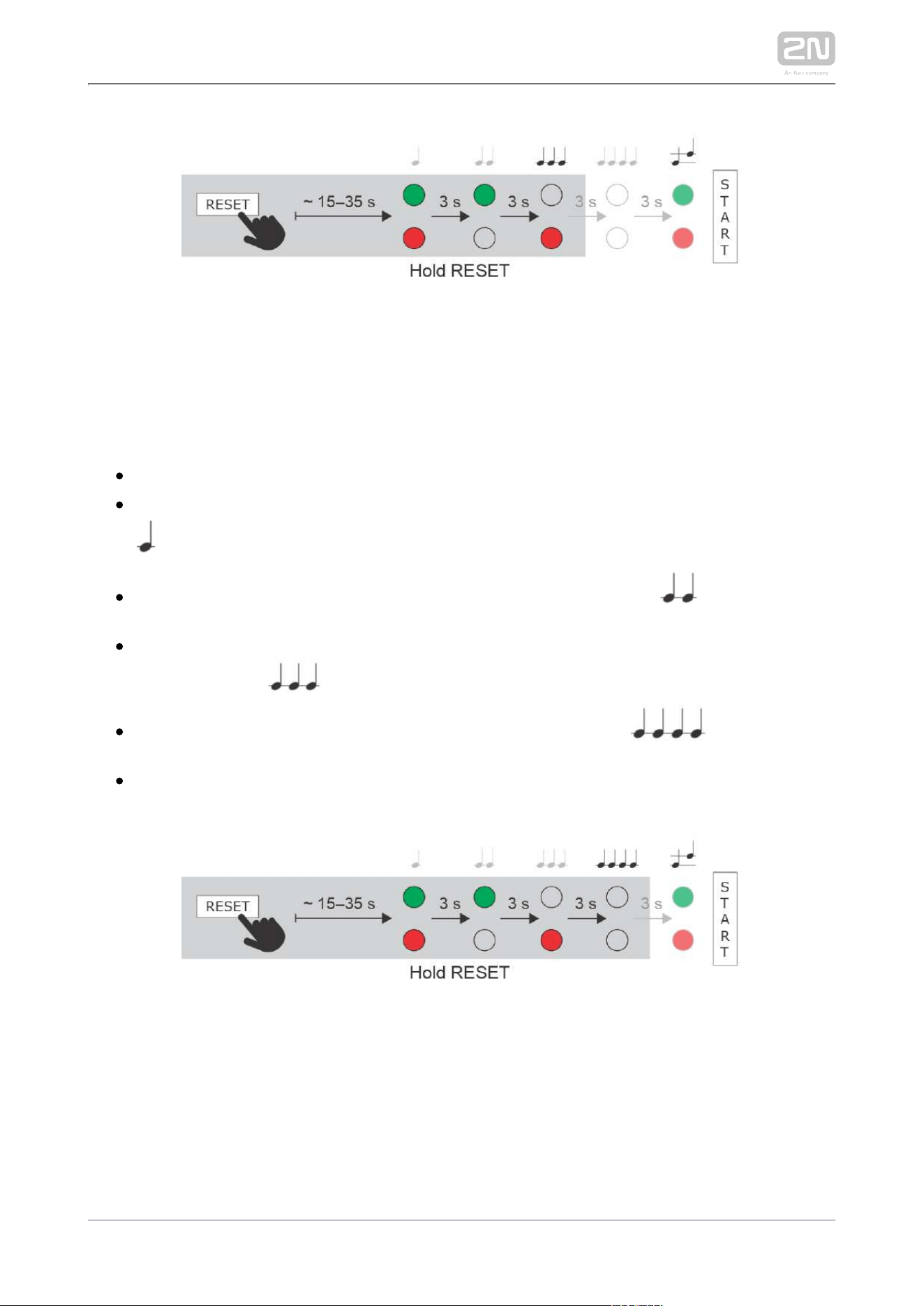
Dynamic IP Address Setting
Follow the instructions below to switch on the mode (DCHP ON):Dynamic IP address
Press and hold the RESET button.
Wait until the red and green LEDs go on simultaneously on the device and the
acoustic signal can be heard (approx. 15–35 s).
Wait until the red LED goes off and the acoustic signal can be heard
(approx. for another 3 s).
Wait until the green LED goes off and the red LED goes on again and the
acoustic signal can be heard (approx. for another 3 s).
Release the RESET button.
2N TELEKOMUNIKACE a.s., www.2n.cz 34/134
Factory Reset
Follow the instructions below to :reset the factory default values
Press and hold the RESET button.
Wait until the red and green LEDs go on simultaneously and the acoustic signal
can be heard (approx. 15–35 s).
Wait until the red LED goes off and the acoustic signal can be heard
(approx. for another 3 s).
Wait until the green LED goes off and the red LED goes on again and the
acoustic signal can be heard (approx. for another 3 s).
Wait until the red LED goes off and the acoustic signal can be heard
(approx. for another 3 s).
Release the RESET button.
2N TELEKOMUNIKACE a.s., www.2n.cz 35/134
Device Restart
Press the RESET button shortly (< 1 s) to restart the system without changing
configuration.
Note
The time interval between the short press of RESET and reconnection
after restart is 18 s for .2N Indoor Compact
®
2N TELEKOMUNIKACE a.s., www.2n.cz 36/134
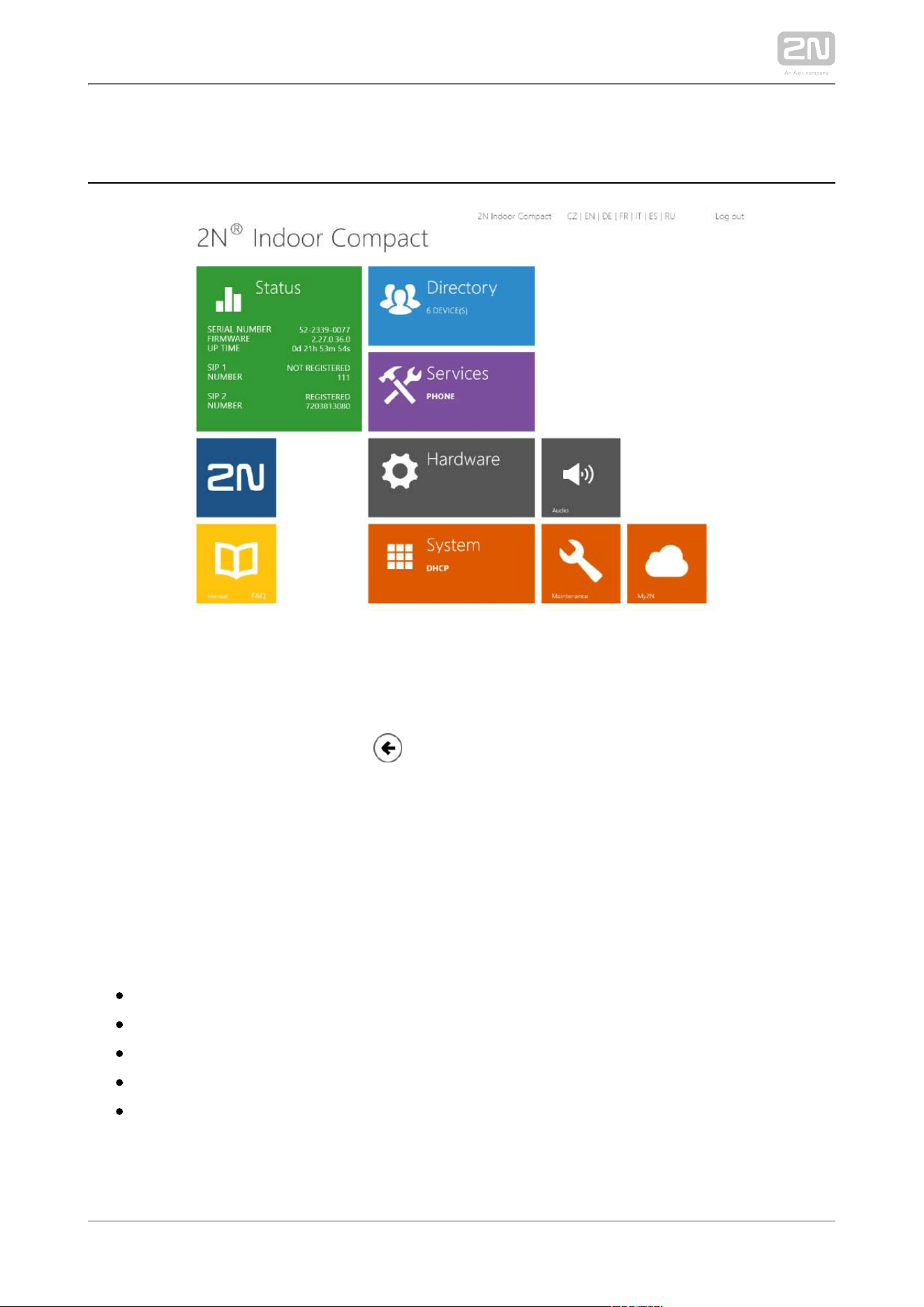
3.2 Software Configuration
Start Screen
The start screen gets displayed when you have logged in to the 2N Indoor Compact
®
web interface. Use the button in the left-hand upper corner on each of the
following web interface pages to return to this screen anytime. The screen header
includes the device name (refer to the Display Name parameter in the Services /
Phone / SIP menu). Use the buttons to select the web interface languages. Click the
Log out button in the right-hand upper corner to log out.
The start screen also provides the first menu level and quick tile navigation to selected
configuration sections. Some tiles also display the state of 2N Indoor Compact
®
selected services.
3.2.1 Status
3.2.2 Directory
3.2.3 Services
3.2.4 Hardware
3.2.5 System
2N TELEKOMUNIKACE a.s., www.2n.cz 38/134
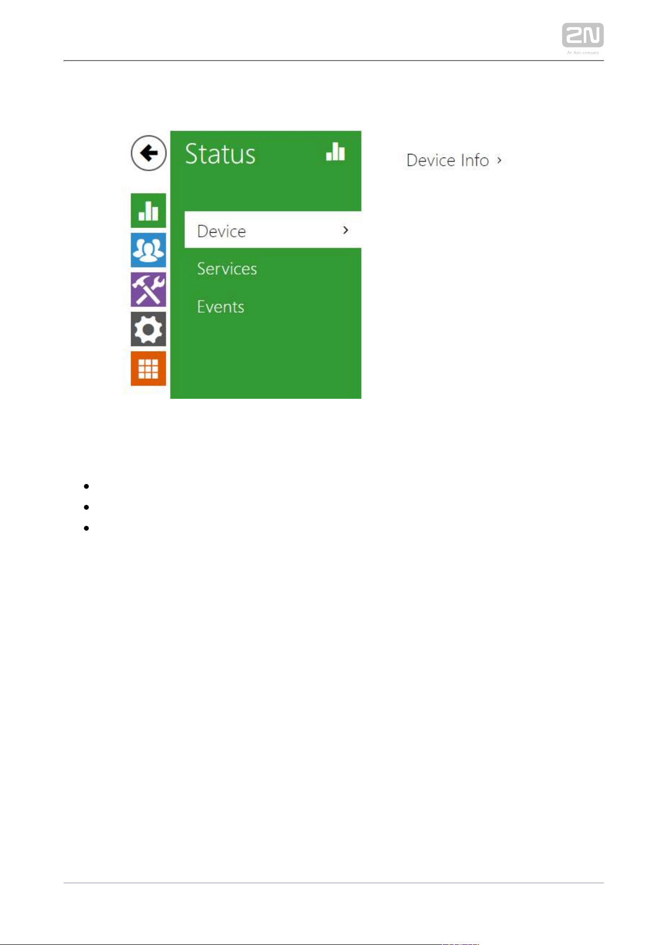
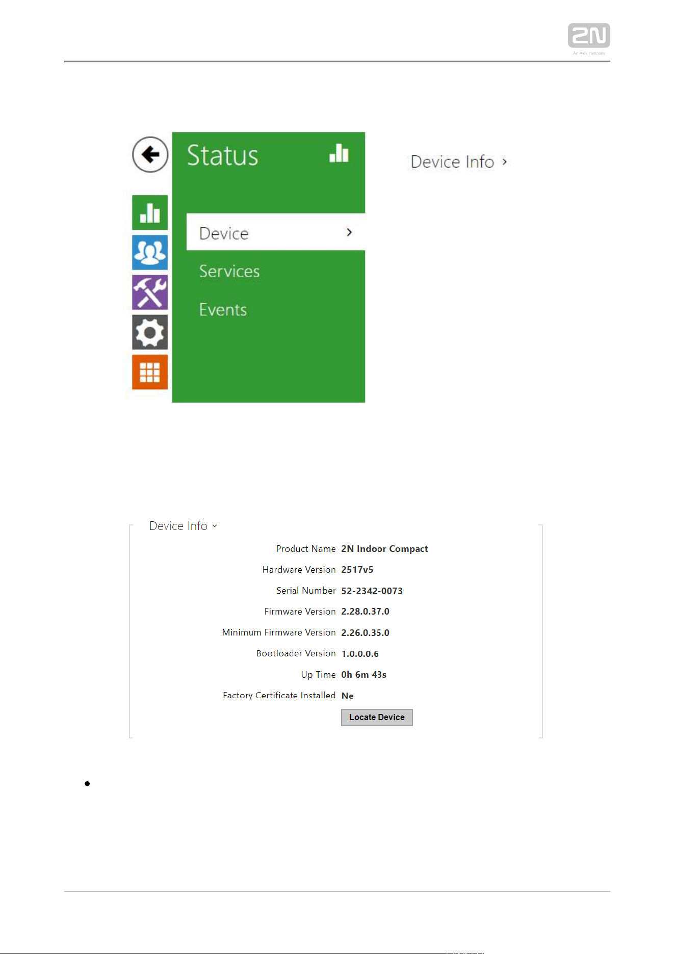
3.2.1.1 Device
Device
The tab displays information on the model, its features, firmware and bootloader
versions, etc.
Factory Certificate Installed – specify the user certificate and private key to
validate the intercom right to communicate with the ACS.

2N TELEKOMUNIKACE a.s., www.2n.cz 39/134
Locate device – optical and acoustic signalling of a device. Optical signalling is
possible only if the device is equipped with control backlight ( , 2N IP Verso
®
2N
®
, , , , a IP Solo 2N IP Base
®
2N IP Vario
®
2N IP Force
®
2N IP Safety
®
2N IP Uni,
®
2N
®
Compact, Talk, Indoor
2N Indoor
®
2N Indoor Touch,
®
2N IP Indoor Toouch 2.0
®
). If a speaker is not integrated in the device, make sure than an external speaker
is connected ( and ) to use sound signalling.2N IP Audio Kit
®
2N IP Video Kit
®
2N TELEKOMUNIKACE a.s., www.2n.cz 40/134
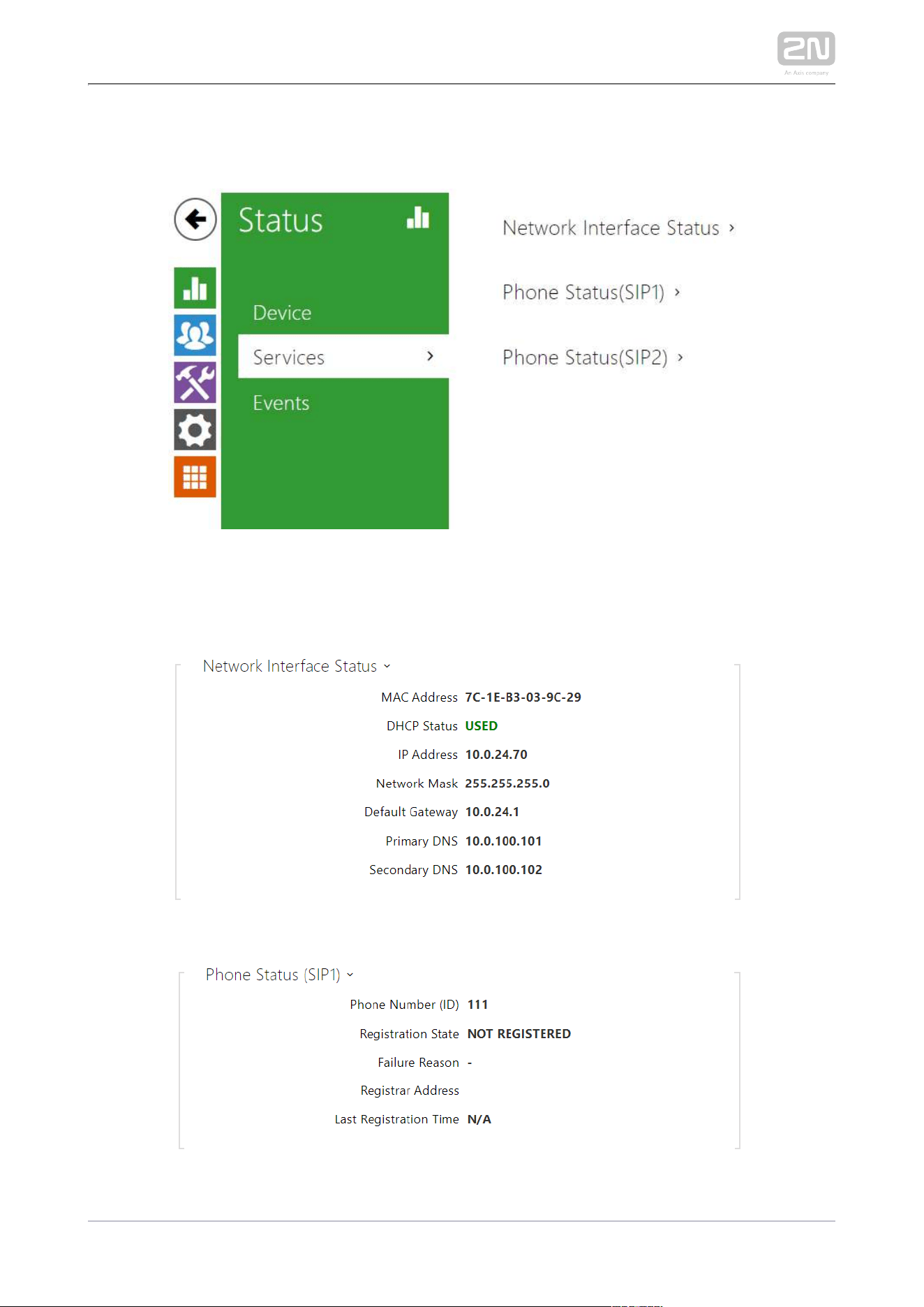
3.2.1.2 Services
Services
The Services tab displays the status of the network interface and selected services.

2N TELEKOMUNIKACE a.s., www.2n.cz 41/134
2N TELEKOMUNIKACE a.s., www.2n.cz 42/134
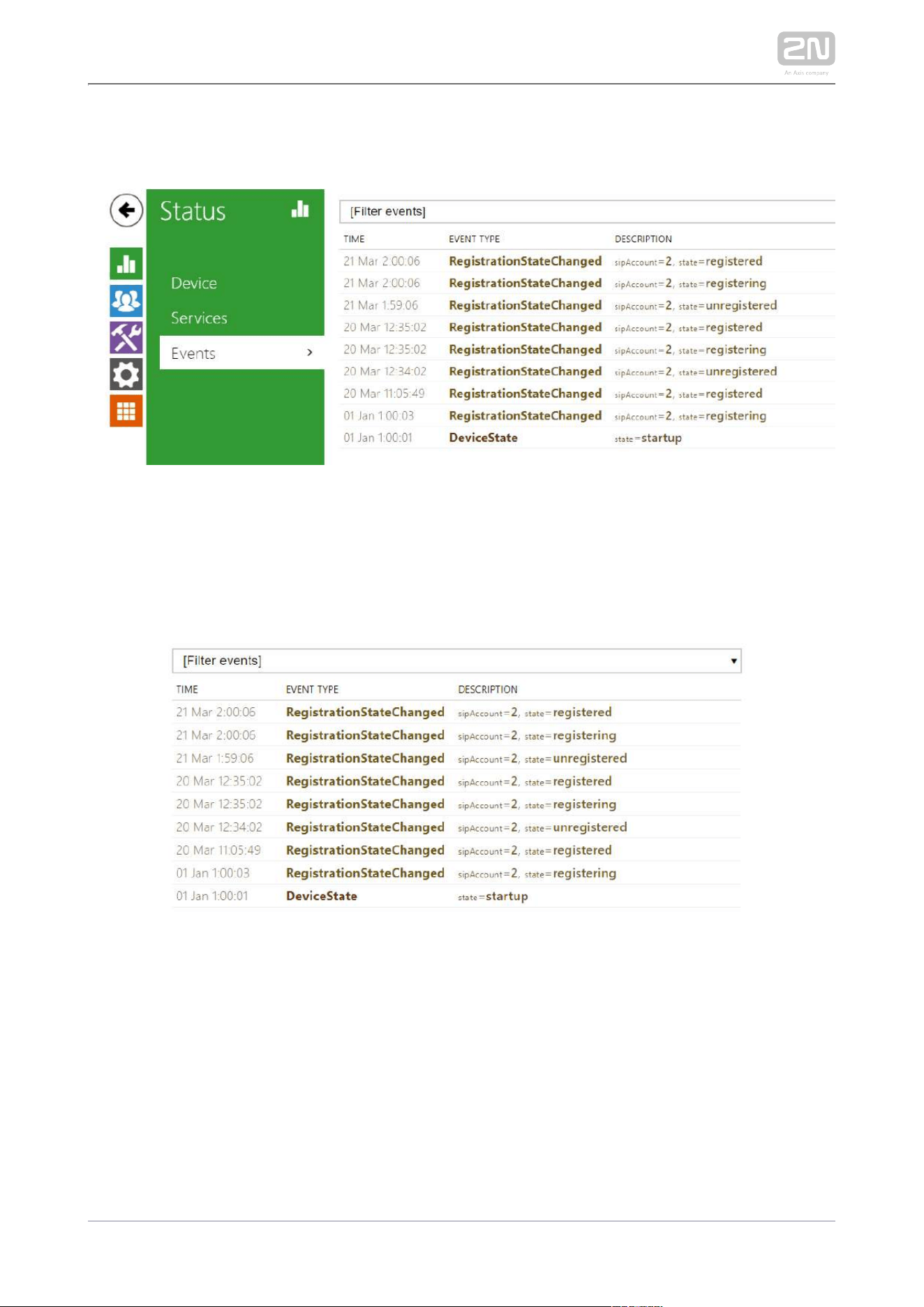
3.2.1.3 Events
Events
The tab displays the last 500 events captured by the device. Every event includes the
capturing time and date, event type and detailed description. The events can be
filtered by type in a dropdown menu above the event log.
2N TELEKOMUNIKACE a.s., www.2n.cz 43/134
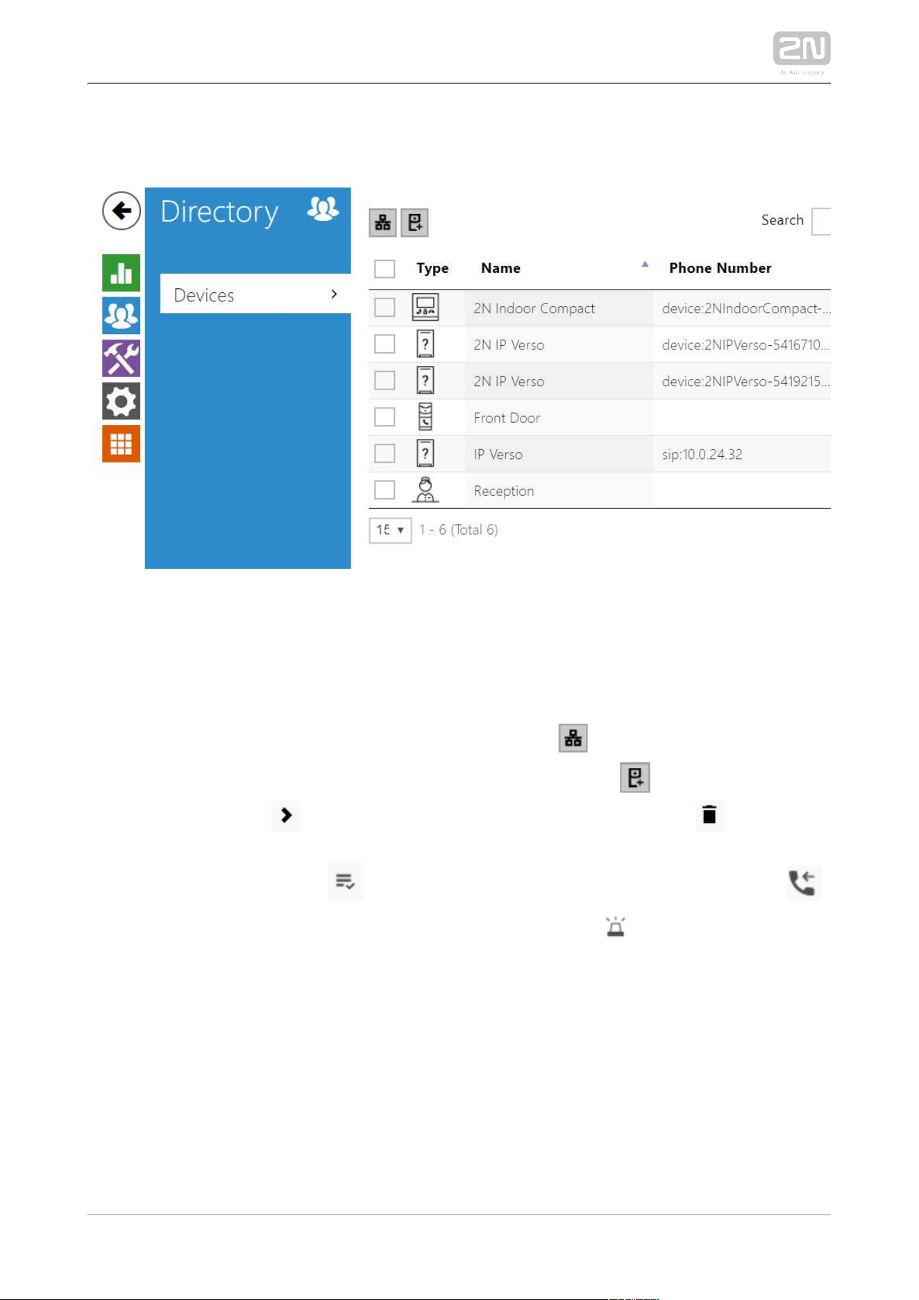
3.2.2 Directory
Directory is one of the crucial parts of the device configuration. It helps add new
devices (2N IP intercoms and other answering units) and provides essential
information on them.
The Search function works as a fulltext search in names and phone numbers. It
searches for all matches in the whole directory. The icon helps find registered
devices and add them to the Directory list if necessary. The icon helps create a
new device and the icon displays the user settings details. The icon helps
remove a device from the list deleting all its data. You can arrange the list according
to the name or feature ( indicates that the device may be displayed,
indicates that incoming calls are allowed to the device and indicates the feature
). of the device to which the alarm call started with a doorbell button press is created
One list page can include 15, 25 or 50 devices.
2N TELEKOMUNIKACE a.s., www.2n.cz 44/134
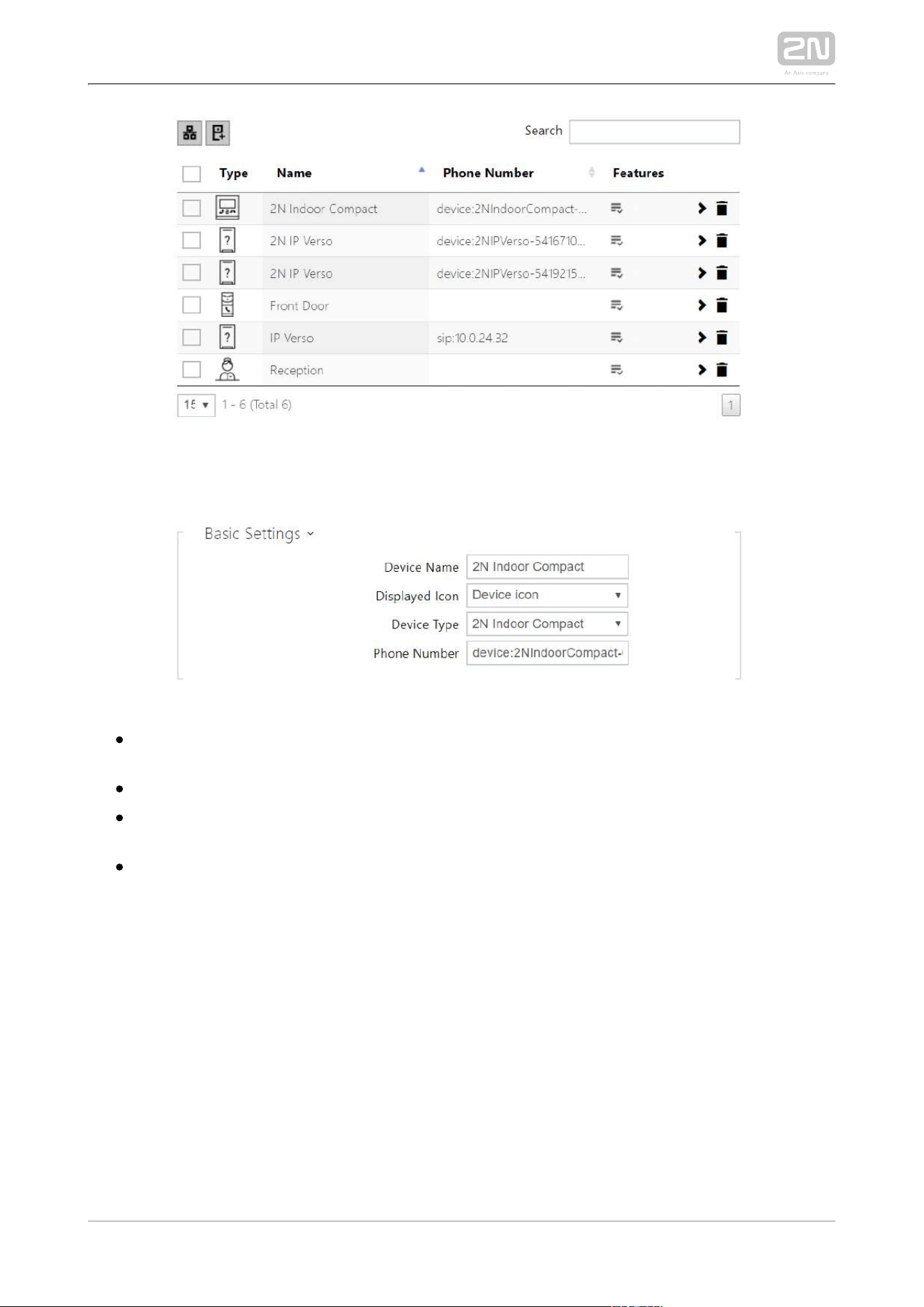
Each device list item includes the following data:
Device Name – enter the device name for the selected Phone Book position. This
parameter is optional and helps you find items in the Phone Book more easily.
Displayed Icon – display the reception desk symbol or a standard symbol.
Device Type – set this parameter manually or automatically using the search for
registered devices in the directory.
Phone Number – set the phone number for the call to be directed to. Enter sip:
[user_id@]domain[:port] for Direct SIP calling, e.g.: sip:[email protected].15 or sip:
name@yourcompany. Enter device:device_name for calls to the 2N IP Mobile
®
application. Set the device name in the mobile application. Enter or behind /1 /2
the phone number to specify which SIP account shall be used for outgoing calls
(account 1 or 2). Enter /S or /N to force an encrypted or unencrypted call
respectively. The account and encryption selections can be combined into the
suffix /1S, for example.
2N TELEKOMUNIKACE a.s., www.2n.cz 45/134
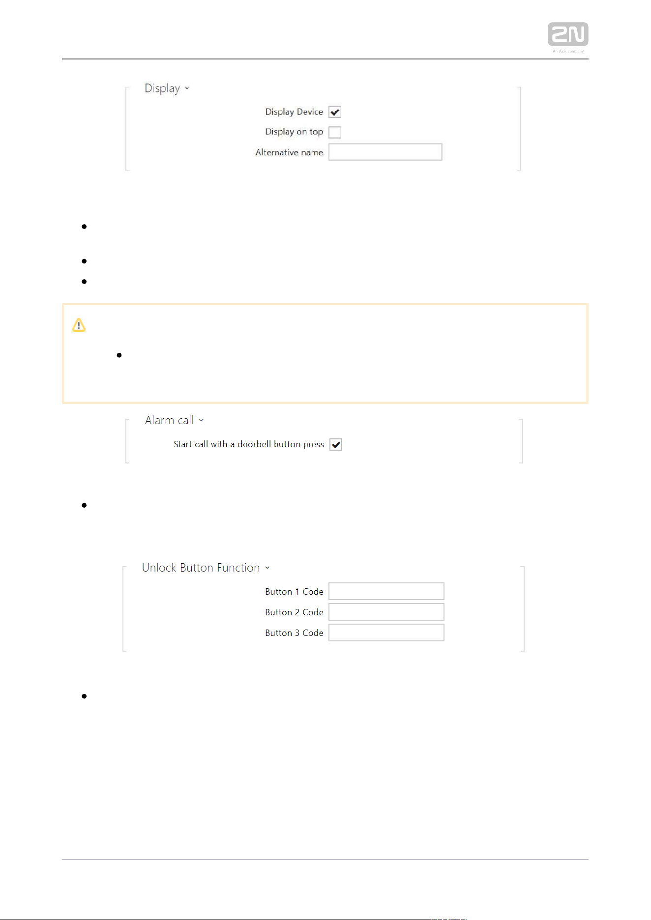
Display Device – display this device. The user can select and call for any device
displayed.
Display on top – display the device on the top.
Alternative name – display an alternative name instead of the device name.
Caution
The <, > and / characters are not allowed for the Device name and
Alternative name parameters.
Start call with a dorbell button press – a phone call to this device will be set up
after the call button is pressed. Set alarm call activation for the doorbell in the
HW / Digital inputs / Doorbell button section.
Button 1,2,3 Code – enter the code assigned to unlock button #1, #2, #3. It is
used for remote unlocking of the entrance door, for example. Make sure that the
code includes at least two door unlocking characters via the intercom keypad
and at least one door unlocking DTMF character via a phone. Four characters at
least are recommended.

2N TELEKOMUNIKACE a.s., www.2n.cz 47/134
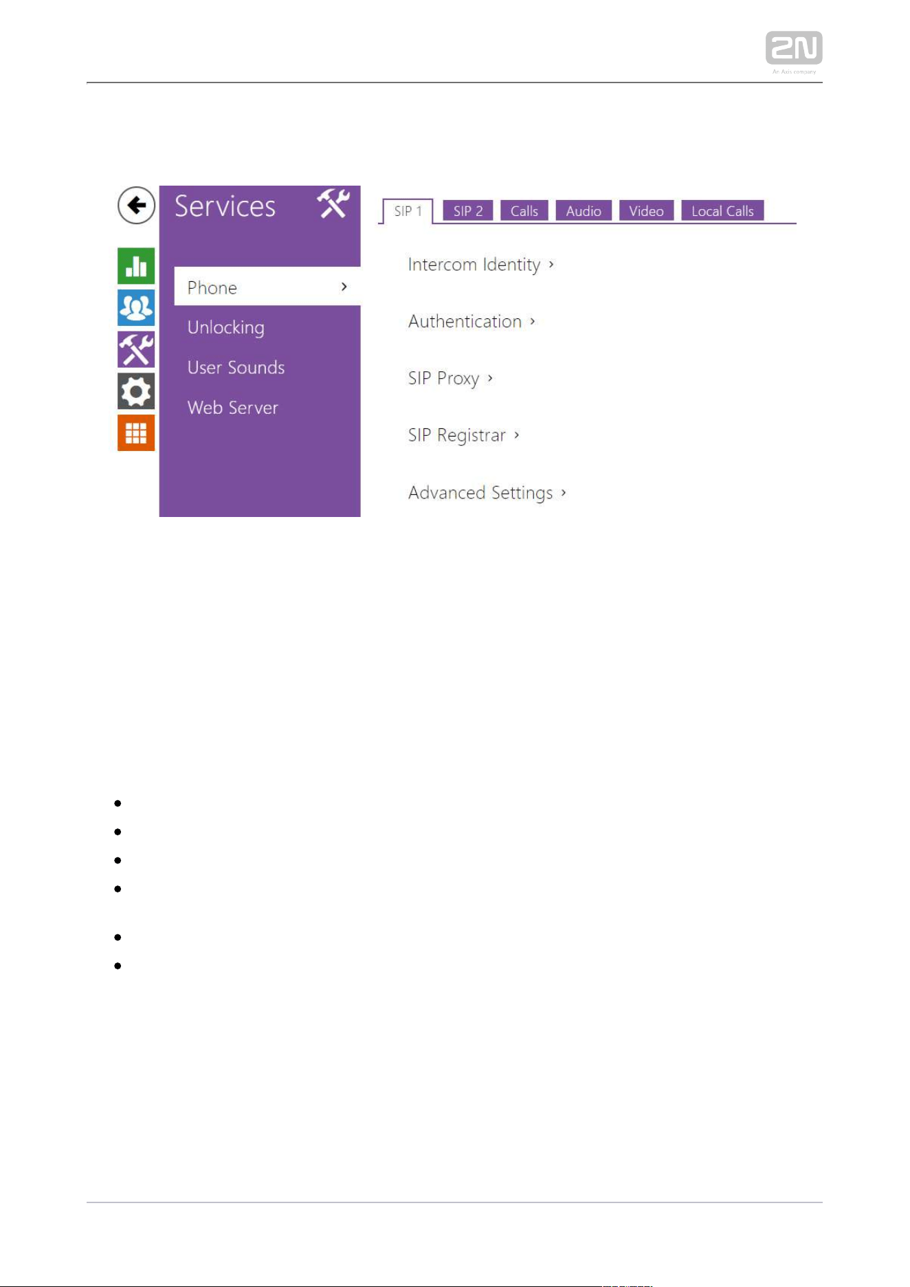
3.2.3.1 Phone
Phone is the basic function of allowing you to establish 2N Indoor Compact
®
connections with other IP network terminals. supports the 2N Indoor Compact
®
extended SIP.
List of Parameters
2N Indoor Compact
®
Phone includes the following four tabs:
SIP 1– complete SIP account settings.
SIP 2– complete SIP account settings.
Calls – incoming and outgoing call settings.
Audio – audio codec, DTMF and other audio stream parameter transmission
settings.
Video – video codec and SDP codec settings.
2N Indoor Units – general parameters and count of identified LAN devices.
SIP 1 and SIP 2
2N Indoor Compact
®
helps you configure one SIP account.
2N TELEKOMUNIKACE a.s., www.2n.cz 48/134
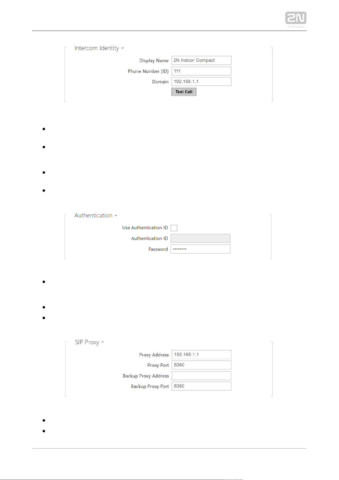
Display Name – set the name to be displayed as CLIP on the called party's
phone.
Phone Number (ID) – set your device phone number (or another unique ID
composed of characters and digits). Together with the domain, this number
uniquely identifies the device in calls and registration.
Domain – set the domain name of the service with which the device is registered.
Typically, it is equivalent to the SIP Proxy or Registrar address.
Test Call – display a dialogue window enabling you to make a test call to a
selected phone number, see below.
Use Authentication ID – select the use of an alternative ID for device
authentication. Otherwise, the Phone number value from the previous section is
used for authentication.
Authentication ID – set the alternative user ID for device authentication.
Password – set the device authentication password. If your PBX requires no
authentication, the parameter will not be applied.
Proxy Address – set the SIP Proxy IP address or domain name.
Proxy Port – set the SIP Proxy port (typically 5060).
Backup Proxy Address – set the backup SIP Proxy IP address or domain name.
2N TELEKOMUNIKACE a.s., www.2n.cz 49/134
Backup Proxy Address – set the backup SIP Proxy IP address or domain name.
The address is used where the main proxy fails to respond to requests.
Backup Proxy Port – set the backup SIP Proxy port (typically 5060).
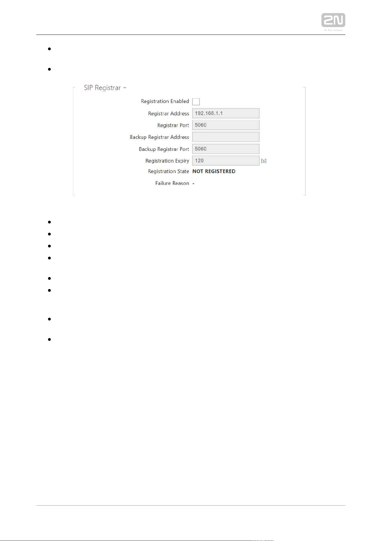
Registration Enabled – enable device registration with the set SIP Registrar.
Registrar Address – set the SIP Registrar IP address or domain name.
Registrar Port – set the SIP Registrar port (typically 5060).
Backup Registrar Address – set the backup SIP Registrar IP address or domain
name. The address is used where the main registrar fails to respond to requests.
Backup Registrar Port – set the backup SIP registrar port (typically 5060).
Registration Expiry – set the registration expiry, which affects the network and
SIP Registrar load by periodically sent registration requests. The SIP Registrar
can alter the value without letting you know.
Registration State – display the current registration state (Unregistered,
Registering..., Registered, Unregistering...).
Failure Reason – display the reason for the last registration attempt failure: the
registrar’s last error reply, e.g. 404 Not Found.
2N TELEKOMUNIKACE a.s., www.2n.cz 50/134
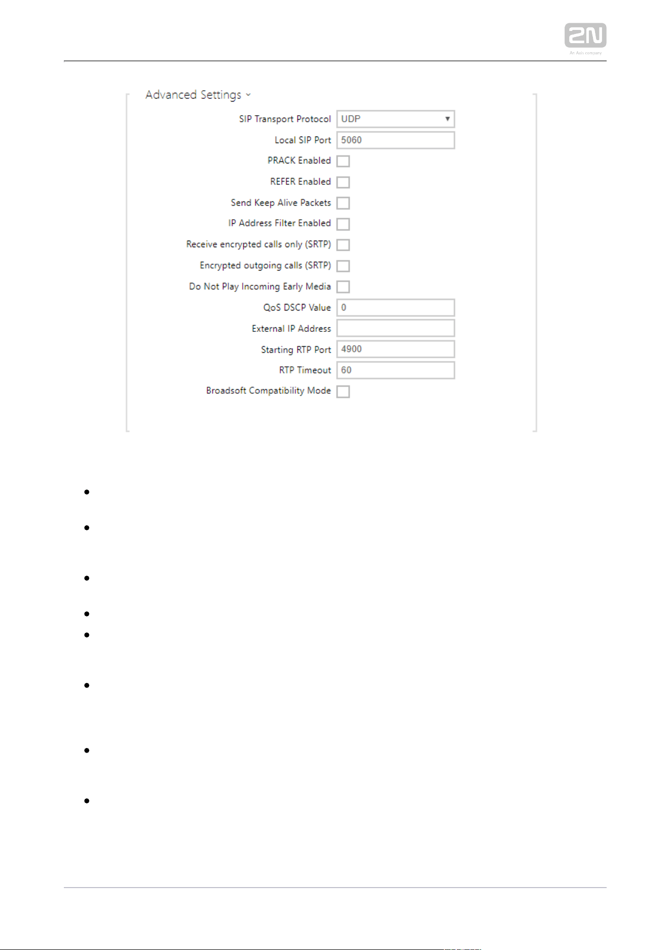
SIP Transport Protocol – set the SIP communication protocol: UDP (default), TCP
or TLS.
Local SIP Port – set the local port for thedevice for SIP signaling. A change of
this parameter will not be applied until the deviceis restarted. The default value
is 5060.
PRACK Enabled – enable the PRACK method for reliable confirmation of SIP
messages with codes 101–199.
REFER Enabled – enable call forwarding via the REFER method.
Send Keep Alive Packets – set that the device shall inquire periodically about the
state of the called station via SIP OPTIONS requests during the call (used for
station failure detection during the call).
IP Address Filter Enabled – enable the blocking of SIP packet receiving from
addresses other than SIP Proxy and SIP Registrar. The primary purpose of the
function is to enhance communication security and eliminate unauthorized
phone calls.
Receive encrypted calls only (SRTP) – set that SRTP encrypted calls shall only
be received on this account. Unencrypted calls will be rejected. At the same
time, TLS is recommended as the SIP transport protocol for higher security.
Encrypted outgoing calls (SRTP) – set that outgoing calls shall be SRTP
encrypted on this account. At the same time, TLS is recommended as the SIP
transport protocol for higher security.
2N TELEKOMUNIKACE a.s., www.2n.cz 51/134
Do Not Play Incoming Early Media – disable playing of the incoming audio
stream before the call sent by some PBXs or other devices is picked up (early
media). A standard local ringtone is played instead.
QoS DSCP Value – set the SIP packet priority in the network. The set value is
sent in the TOS (Type of Service) field in the IP packet header. Enter the value as
a decimal number. A change of this parameter will not be applied until the
deviceis restarted.
External IP Address – set the public IP address or router name to which the
device is connected. If the device IP address is public, leave this parameter
empty.
Starting RTP Port – set the initial local RTP port in the range of 64 ports used for
audio and video transmission. The default value is 4900 (i.e. the range is 4900–
4963). The parameter is only set for account 1 but applies to both the SIP
accounts.
RTP Timeout – set the audio stream RTP packet receiving timeout during a call.
If this limit is exceeded (RTP packets are not delivered), the call will be
terminated by the device. Enter 0 to disable this parameter. The parameter is
only set for account 1 but applies to both the SIP accounts.
Broadsoft Compatibility Mode – set the Broadsoft PBX compatibility mode.
Having received re-invite from a PBX in this mode, the intercom replies by
repeating the last sent SDP with currently used codecs instead of sending a
complete offer.
Calls
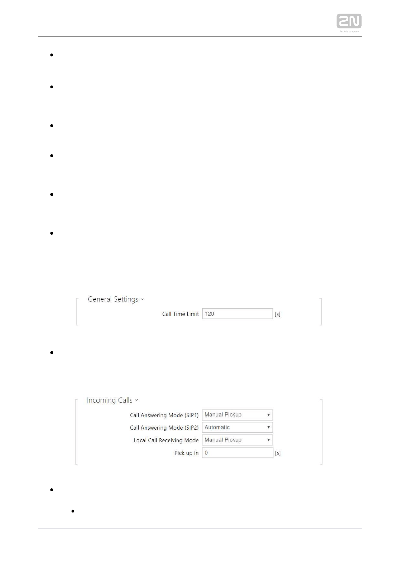
Call Time Limit – set the call time limit after which the call is automatically
terminated. The intercom signals termination with a beep 10 s before the call
end. Enter any DTMF character into the call (# on your IP phone, e.g.) to extend
the call time.
Call Answering Mode (SIP 1, SIP 2) – set the way of receiving incoming calls. The
following three options are available:
Always busy – the device rejects incoming calls.
2N TELEKOMUNIKACE a.s., www.2n.cz 52/134
Manual Pickup – the device rings to signal incoming calls and the user can
press a keypad button to pick up.
Automatic – the device picks up incoming calls automatically. You can set
the call receiving mode for each SIP account separately.
Local Call Receiving Mode – set the way of receiving incoming local calls. The
following three options are available:
Always busy – the device rejects incoming calls.
Manual Pickup – the device rings to signal incoming calls and the user can
press a keypad button to pick up.
Automatic – the device picks up incoming calls automatically. You can set
the call receiving mode for each SIP account separately.
Pick up in – this parameter is only active when the Automatic pickup mode is
enabled. The call is picked up automatically after the preset timeout elapses.
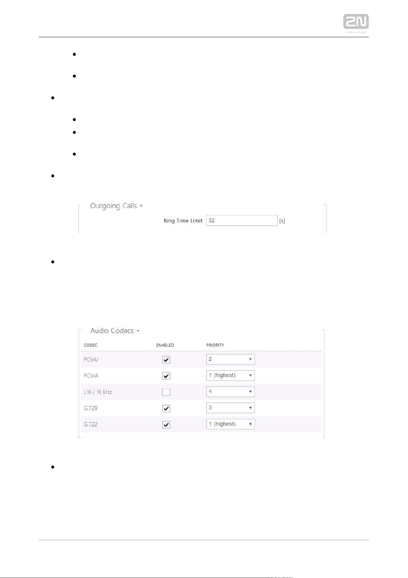
Ring Time Limit – set the maximum call setup and ringing time in which all
outgoing calls are automatically terminated. If the calls are routed to the GSM
network via GSM gateways, you are advised to set a value longer than 20 s.
Minimum value: 1 s, maximum value: 600 s. Set 0 to disable the time parameter.
Audio
Enable/disable the use of audio codecs for call setups and set their priorities.
2N TELEKOMUNIKACE a.s., www.2n.cz 53/134
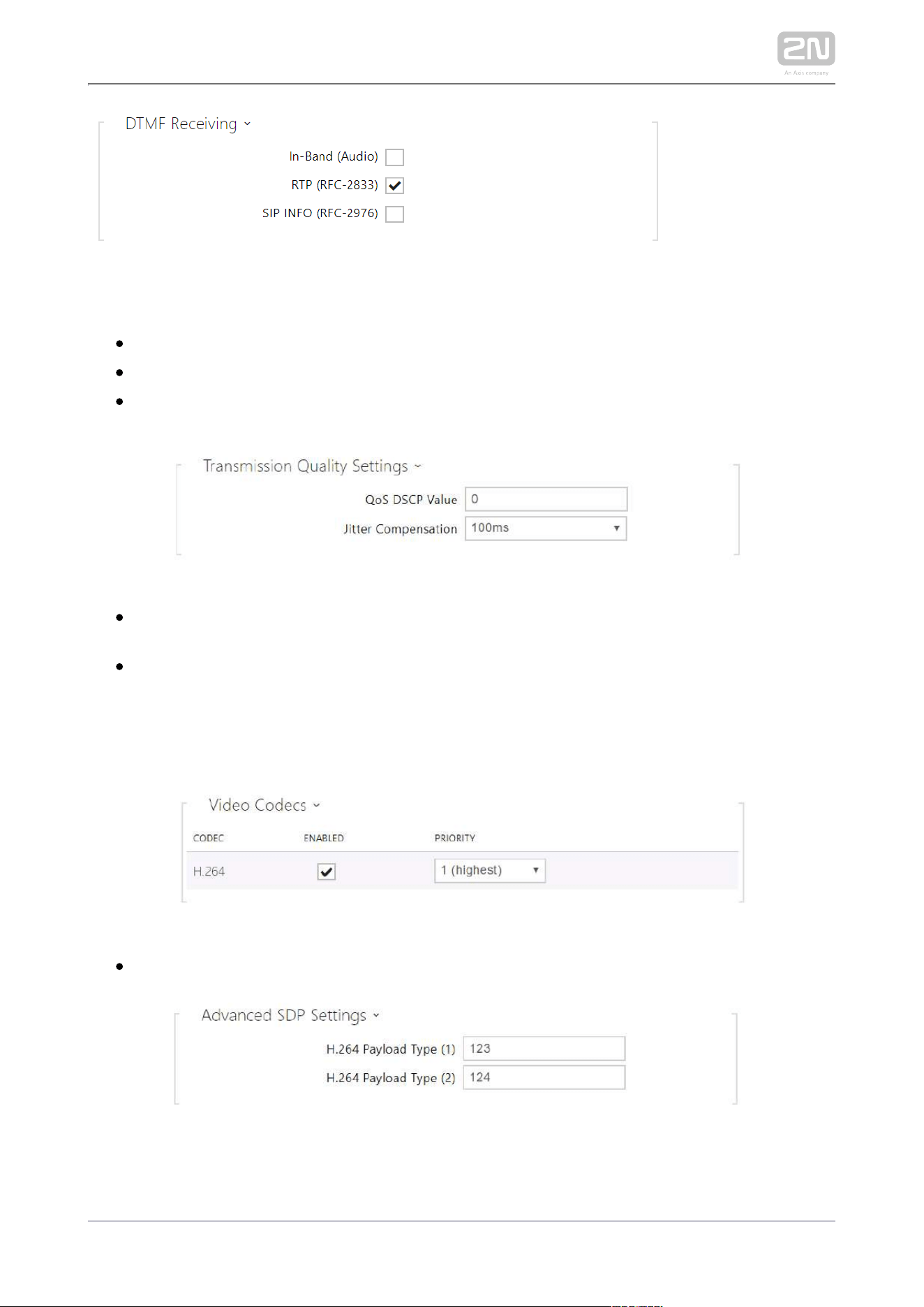
The tab below helps you define how DTMF characters shall be received from the intercom. Check the
opponent’s DTMF receiving options and settings to make the function work properly.
In-Band (Audio) – enable classic DTMF dual tone receiving in the audio band.
RTP (RFC-2833) – enable DTMF receiving via RTP according to RFC-2833.
SIP INFO (RFC-2976) – enable DTMF receiving via SIP INFO messages according
to RFC-2976.
QoS DSCP Value – set the audio RTP packet priority in the network. The set
value is sent in the TOS (Type of Service) field in the IP packet header.
Jitter Compensation – set the buffer length for compensation of interval
unevenness in audio packet arrivals. A higher capacity improves the transmission
resistance at the cost of a greater sound delay.
Video
Enable/disable the use of video codecs for call setups and set their priorities.
2N TELEKOMUNIKACE a.s., www.2n.cz 54/134
H.264 Payload Type (1), (2) – set the video codec H.264 payload type
(packetization mode 1). Set a value from the range of 96 through 127, or 0 to
disable this codec type.
Local Calls
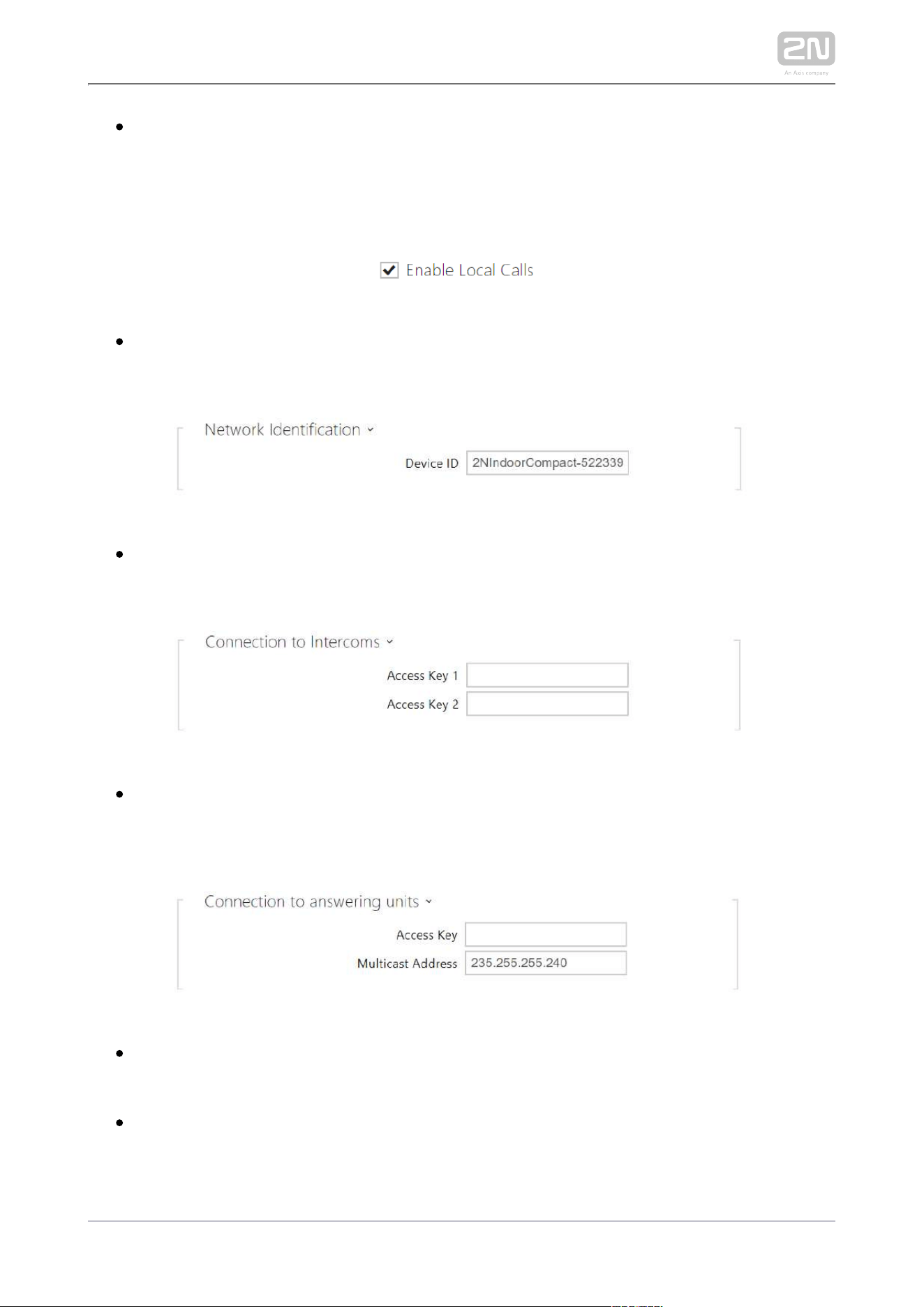
Enable Local Calls – enable calls between devices in the LAN. With this function
off, the other LAN devices cannotlocate this device, i.e. cannot call the device in
the device:device_ID format.
Device ID – Set the device ID to be displayed in the LAN device list in all the 2N
devices in one and the same LAN. You can direct a call to this device by setting
the user phone number as device:device_ID in these devices.
Access Key 1, 2 – set the access key shared by the 2N answering units and
intercoms. If the keys in the 2N answering units and intercoms fail to match, the
device cannot communicate, i.e. the intercom cannot call the 2N answering unit
and vice versa.
Access Key – set the access key shared by the 2N answering units. If the keys in
the 2N answering units fail to match, the answering units cannot communicate, i.
e. the answering units cannot call each other.
Multicast Address – set the network multicast address to which the anwering
unit message shall be sent.

2N TELEKOMUNIKACE a.s., www.2n.cz 55/134
LAN Device count – display the number of local devices in the network.
Show LAN devices list – display a detailed list of local devices in the network.
2N TELEKOMUNIKACE a.s., www.2n.cz 56/134
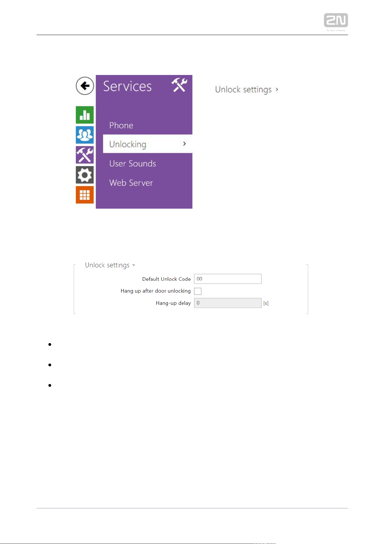
3.2.3.2 Unlocking
is another function of , which sets the remote door Unlocking 2N Indoor Compact
®
unlocking parameters.
Default Unlock Code – use this code when a call has been set up with a device
/phone number that is not added to the unit phone book.
Hang up After Door Unlocking – end the call when the door unlocking request
has been sent successfully.
Hang-up delay – end the call when the door unlocking request sending timeout
has elapsed.
2N TELEKOMUNIKACE a.s., www.2n.cz 57/134
1.
a.
b.
c.
d.
e.
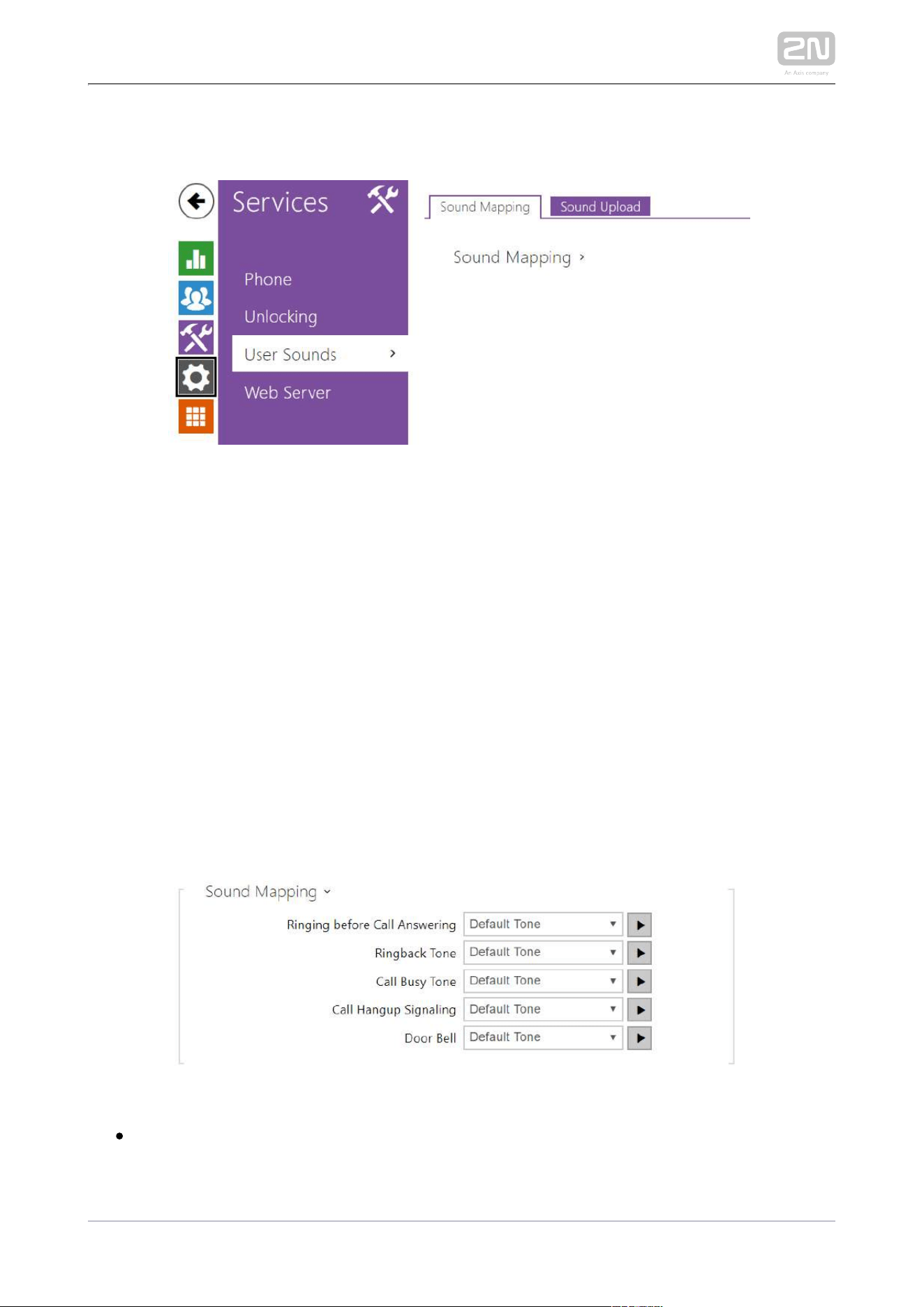
3.2.3.3 User Sounds
2N Indoor Compact
®
signals variable operational statuses with a sequence of tones. If
the standard signaling tones do not meet your requirements, you can modify them.
The device allows you to modify sound signaling for the following states:
Ringtone before call pickup
Ringing tone
Busy tone
Call end signaling
Doorbell
Sound Mapping
Ringing before Call Pickup – set the ringtone to be played before an incoming
call is picked up (device ringtone).
The – set the sound to be played when the called user is ringing. Ringback Tone
2N TELEKOMUNIKACE a.s., www.2n.cz 58/134
The – set the sound to be played when the called user is ringing. Ringback Tone
PBX ringtone is preferred to the user ringtone in the device.
Call Busy Tone – set the tone to be played when the called user is busy.
Call Hang-Up Signaling – set the tone to signal the call end.
Doorbell – set the tone to be played when the doorbell is used.
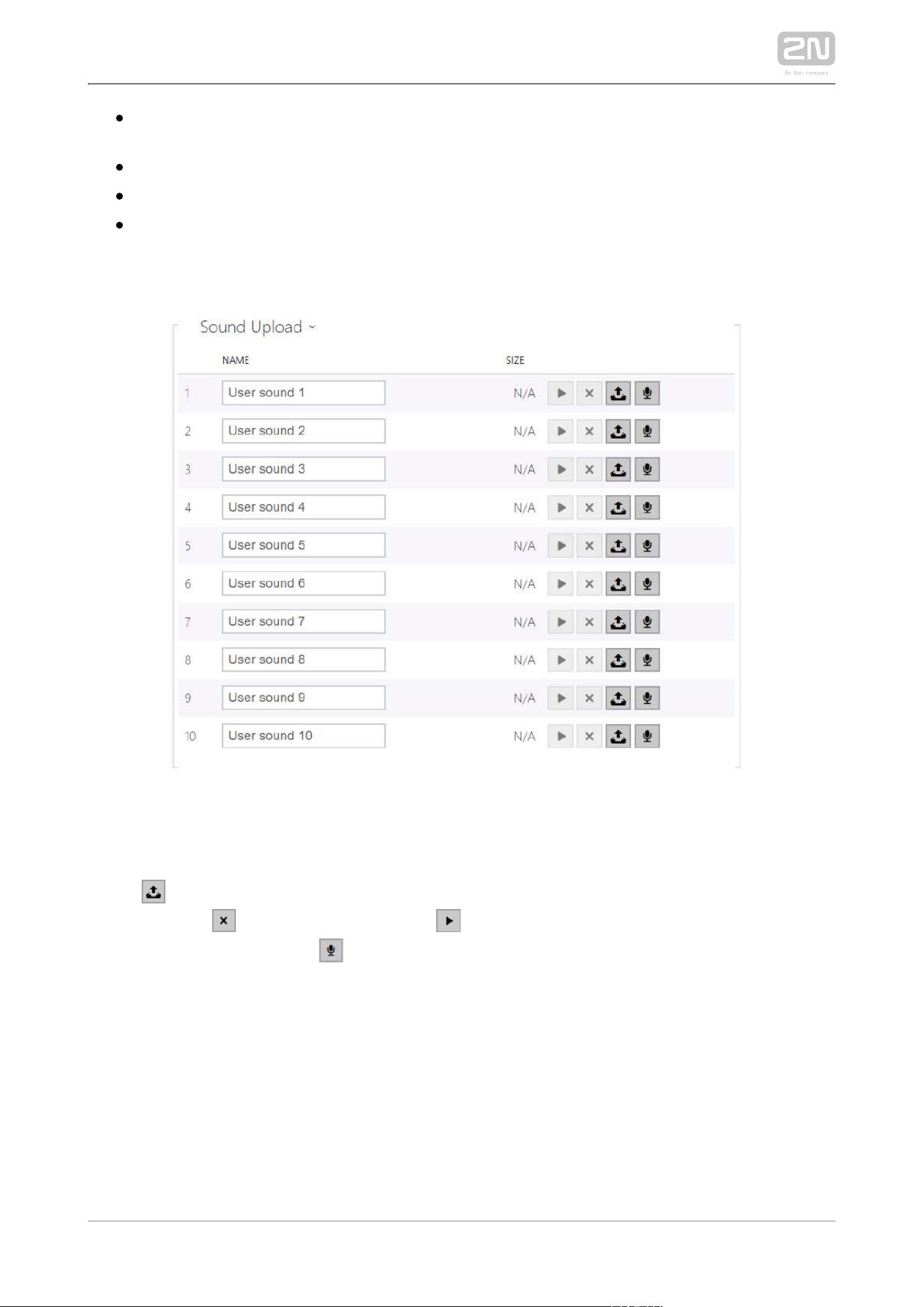
Sound Upload
You can upload up to 10 user sound files to the device and name each of them for
better orientation.
Press to upload a sound file to the device. Select a file from your PC and click
. Press to remove a file. Click to play a successfully uploaded sound file Upload
(locally on your PC). Press to record a sound file via your PC microphone.
2N TELEKOMUNIKACE a.s., www.2n.cz 59/134
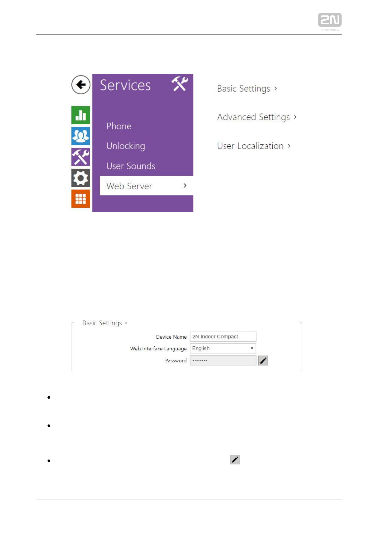
3.2.3.4 Web Server
2N Indoor Compact
®
can be configured using a common browser that approaches the
web server integrated in the device. The HTTPS protocol is used for the browser -
device communication. Enter the login user name and password first. The default
values are and respectively. We recommend to you change the default admin 2n
password as soon as possible.
List of Parameters
– set the device name to be displayed in the right-hand upper Device Name
corner of the web interface, in the login window and in other applications if
necessary (Network Scanner, etc.)
– set the default language after the administration web Web Interface Language
server login. Use the upper toolbar buttons to change the web interface
language temporarily any time.
– set the device login password. Click to edit the password. Make Password
sure that the password contains 8 characters at least, including one small
alphabet letter, one capital alphabet letter and one digit.
2N TELEKOMUNIKACE a.s., www.2n.cz 60/134
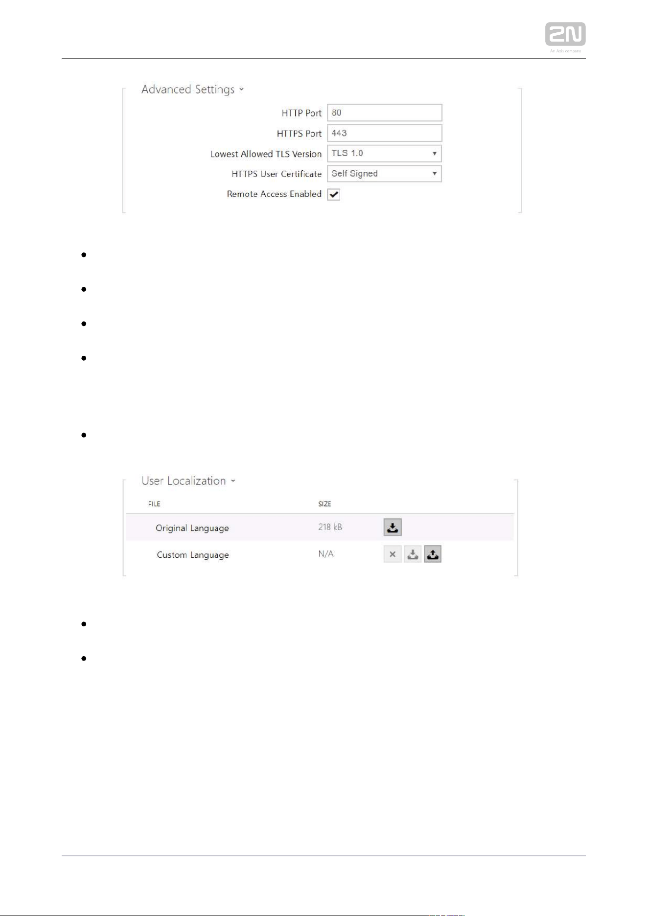
HTTP Port – set the web server port for HTTP communication. The port change
will not be applied until the device is restarted.
HTTPS Port – set the web server port for HTTPS communication. The port
change will not be applied until the device is restarted.
Minimum Allowed TLS Version – set the lowest TLS version to be accepted for
device connection.
HTTPS User Certificate – set the user certificate and private key for
communication encryption between the device HTTP server and the user web
browser. Choose one of the three sets of user certificates and private keys (refer
to the Certificates subs.) or keep the setting, in which the certificate Self Signed
automatically generated upon the first intercom power up is used.
Remote Access Enabled – enable remote access to the device web server from
off-LAN IP addresses.
Original Language – download an original file from the device including all user
interface texts in English. The file format is XML; see below.
Custom Language – upload, download and/or remove user files including
translations of the user interface texts.
2N TELEKOMUNIKACE a.s., www.2n.cz 62/134
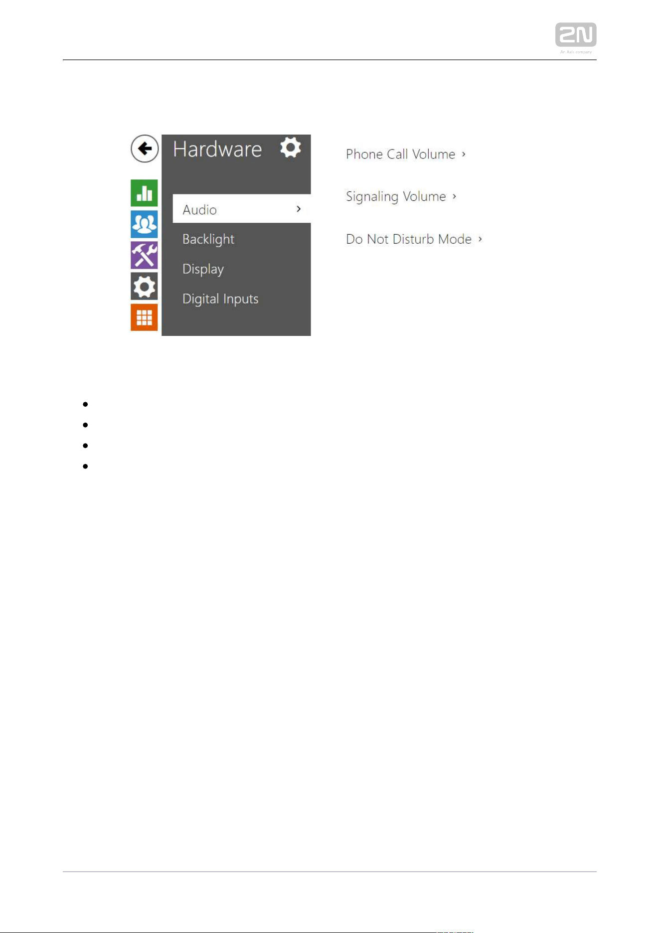
3.2.4.1 Audio
2N Indoor Compact
®
is equipped with a speaker. Set the phone call and state
signaling volume control in this configuration section. controls the Master Volume
general device volume including call volume, signaling tone volume, and so on.
Consider the noise level of the ambient environment while setting this parameter.
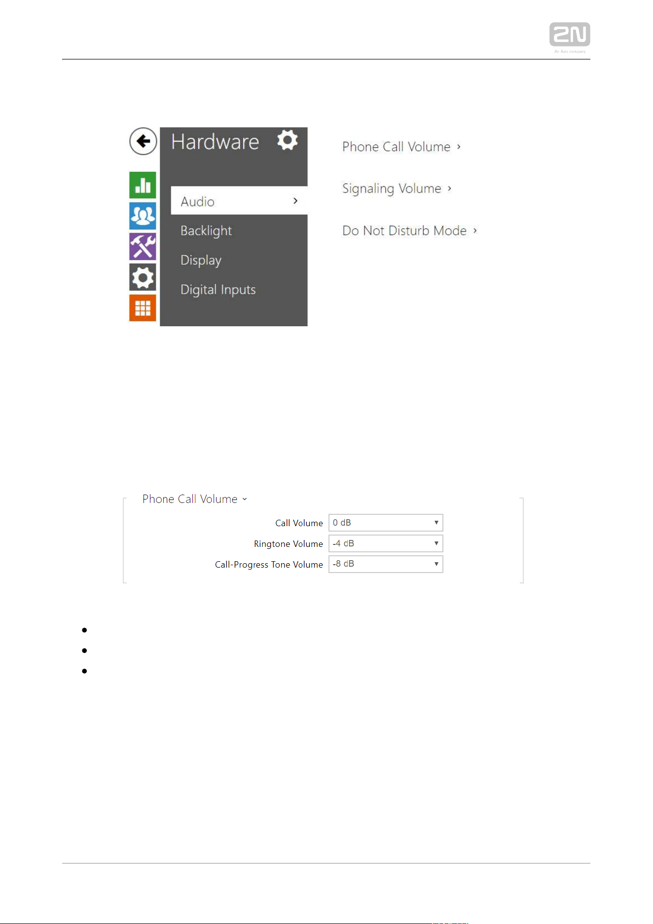
List of Parameters
Call Volume – set the phone call volume.
Ringtone Volume – set the incoming call ringtone volume.
Call-Progress Tone Volume – set the dialtone, ringtone and busy tone volume
levels. In case the call progress tones are automatically generated by the PBX,
this setting will not be applied.
2N TELEKOMUNIKACE a.s., www.2n.cz 63/134
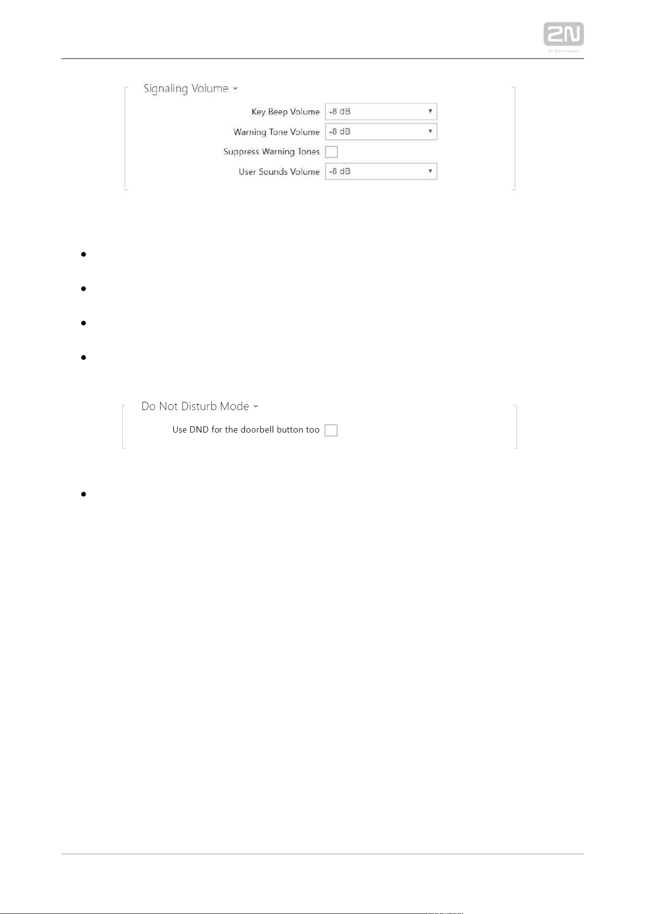
Key Beep Volume – set the key beep volume. The volume values are relative
against the set master volume.
Warning Tone Volume – set the volume of warning and signaling tones. The
volume values are relative against the set master volume.
Suppress Warning Tones – suppress signaling of the following operational
states: Internal application started, IP address received and IP address lost.
User Sound Volume – set the volume of the user sounds. The volume values are
relative against the set master volume.
Use DND for the doorbell button too – if this function is activated, the device
shall not ring when the doorbell button is pressed.
2N TELEKOMUNIKACE a.s., www.2n.cz 64/134
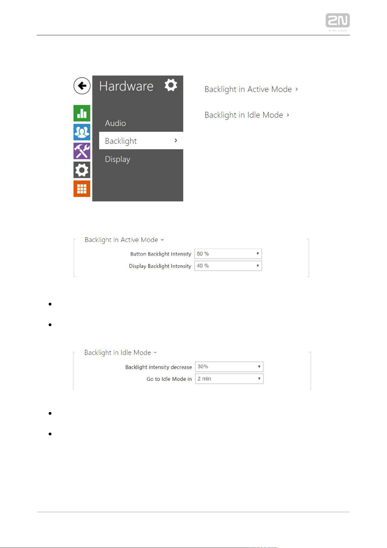
3.2.4.2 Backlight
Set the backlight level separately on this tab.
Button Backlight Intensity – set the backlight brightness level. Set the value as a
percentage of the maximum possible LED brightness.
Display Backlight Intensity – set the backlight brightness level. Set the value as a
percentage of the maximum possible LED brightness.
Backlight Intensity decrease – decrease the backlight brightness while the
device is in the idle mode.
Go to Idle Mode in – set the inactivity timeout after which the device switches to
the idle mode.

2N TELEKOMUNIKACE a.s., www.2n.cz 65/134
Note
The brightness level considerably affects the functionality, consumption
and general appearance of the device. A high backlight value may
dazzle the person standing in front of the device if the ambient light is
low and also increases the overall device consumption.
2N TELEKOMUNIKACE a.s., www.2n.cz 66/134
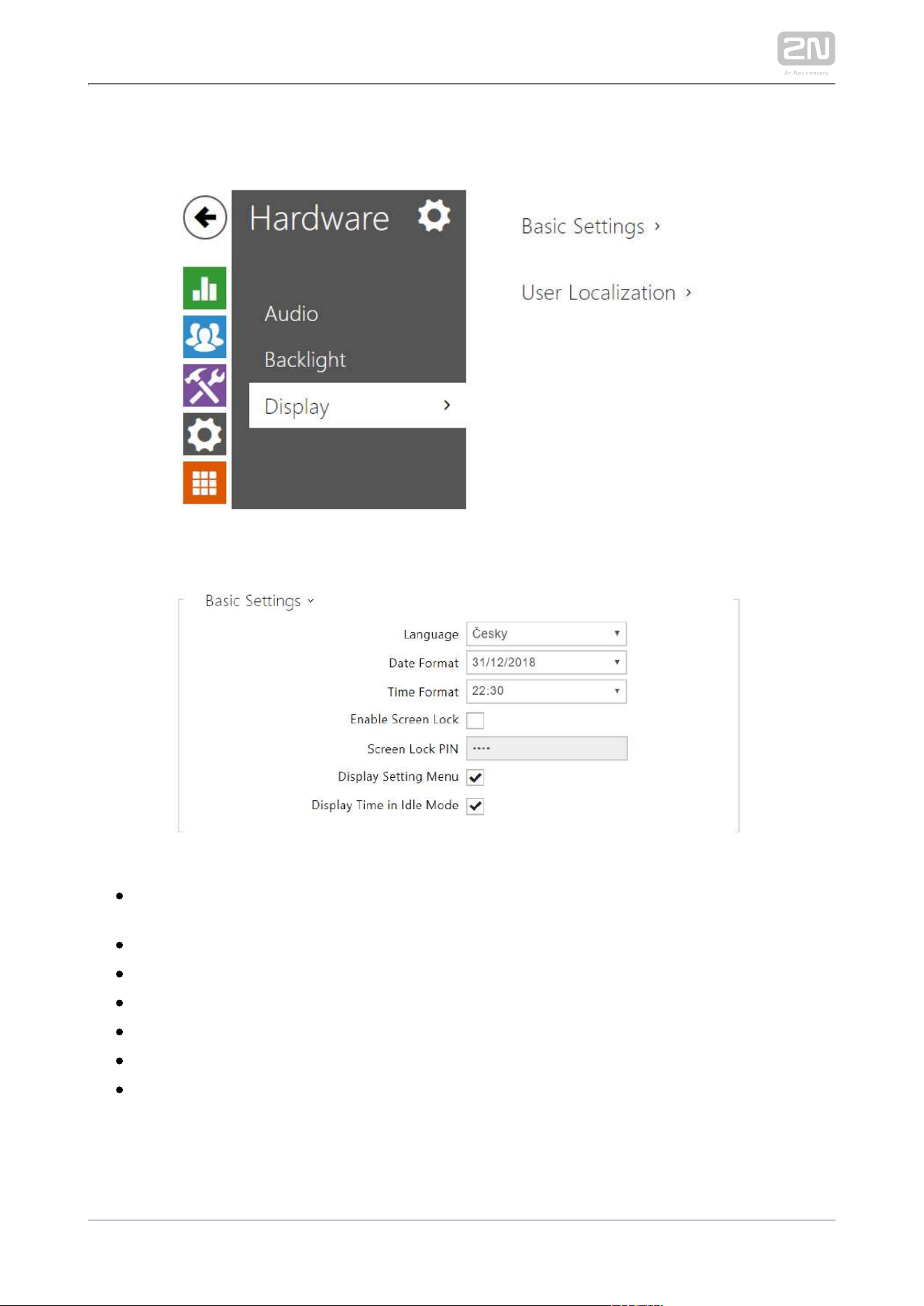
3.2.4.3 Display
Set the basic display parameters on this tab.
Language – set the language for the texts to be displayed. Choose one of the
seven pre-defined languages (CZ, EN, DE, FR, ES, IT, RU).
Date Format – set the date format to be displayed.
Time Format – set the time format to be displayed.
– activate the screen lock function.Enable Screen Lock
– set the screen lock activation/deactivation code.Screen Lock PIN
Display Setting Menu – display the Setting menu.
Display Time in Idle Mode – switch off the device display and all backlight in the
idle mode.
2N TELEKOMUNIKACE a.s., www.2n.cz 67/134
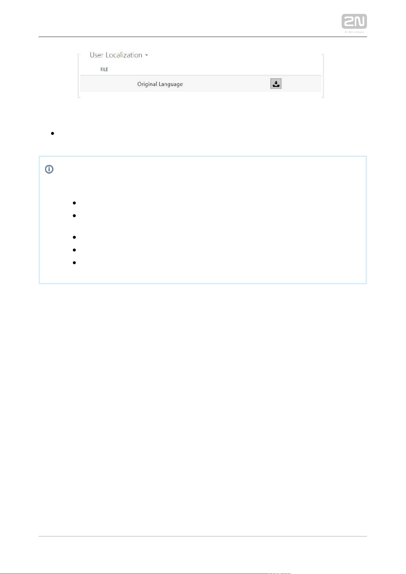
Original Language – download the localization file template for own translation.
It is an XML file with all the texts to be displayed.
Note
If none of the pre-defined languages is convenient for you, proceed as follows:
Download the original language file (English).
Modify the file using a text editor (replace the English texts with your
own ones).
Upload the modified localization file back to the intercom.
Set to .Language Settings | Language Custom
Check and correct if necessary the texts on the intercom display.
2N TELEKOMUNIKACE a.s., www.2n.cz 68/134
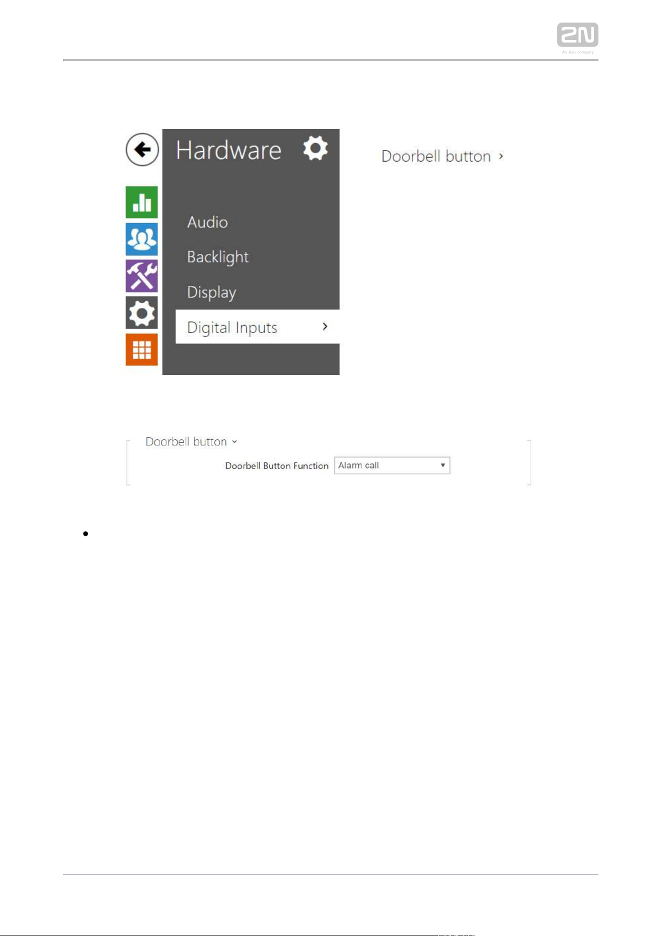
3.2.4.4 Digital Inputs
This subsection describes the digital input options of the device.
Doorbell Button Function – select doorbell function (doorbell, alarm call). The
button is used either as a classical doorbell or for alarm call activation.
2N TELEKOMUNIKACE a.s., www.2n.cz 70/134
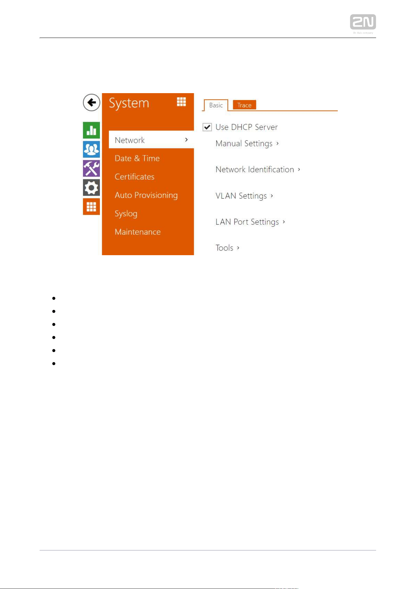
3.2.5.1 Network
To be connected to the LAN properly, has to be assigned a valid 2N Indoor Compact
®
IP address or obtain the IP address from the LAN DCHP server. The Network section
helps you configure the IP address and DHCP.
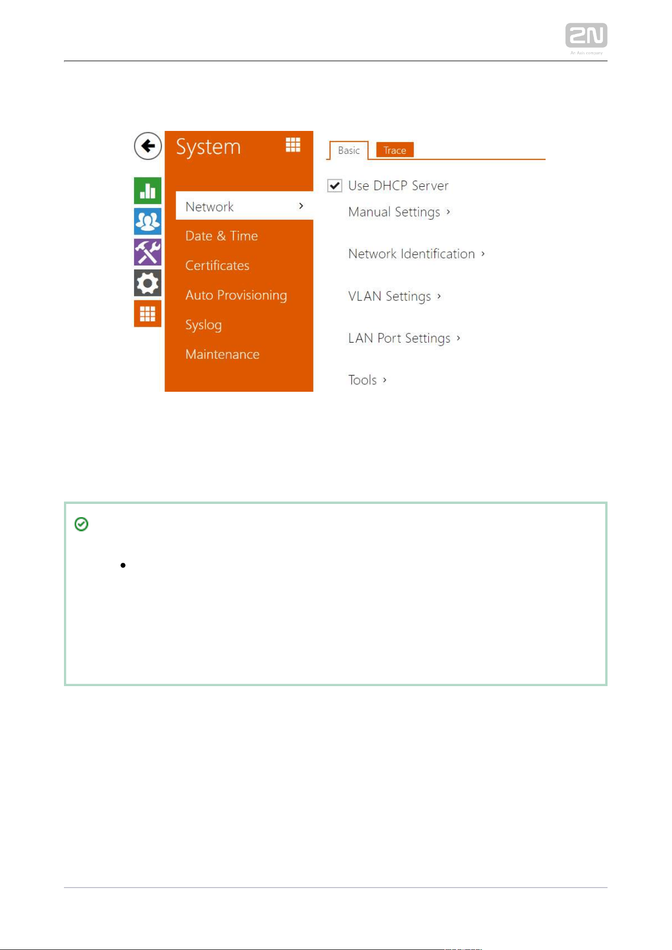
Tip
To look up the current IP address, apply the 2N Indoor Compact
®
2N
®
, which can be downloaded freely from , and Network Scanner www.2n.cz
use the mechanism described in
2.4 2N Indoor Compact LAN Location
®
via 2N Network Scanner.
®
2N TELEKOMUNIKACE a.s., www.2n.cz 71/134
List of Parameters
Network
Basic
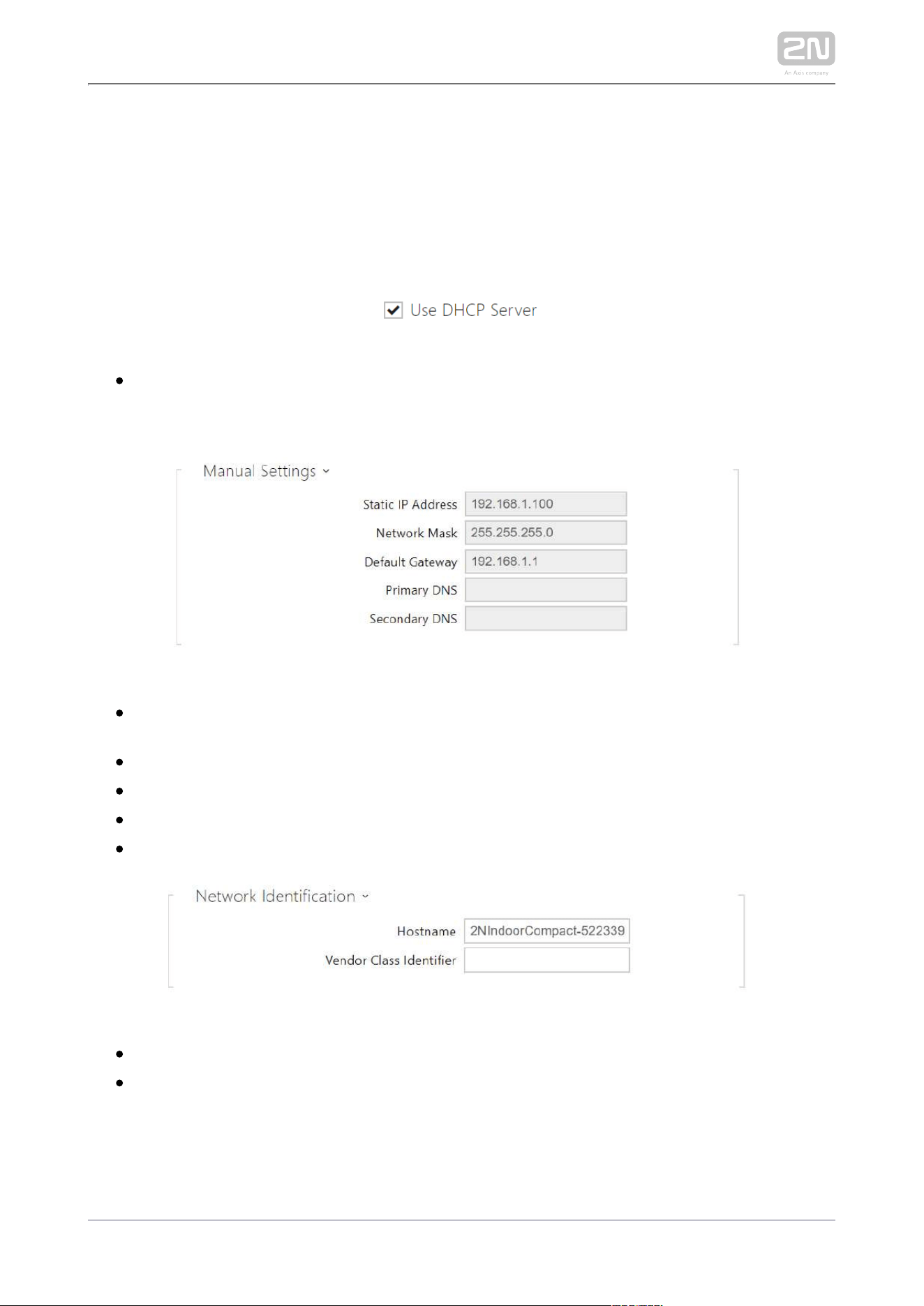
Use DHCP server – enable automatic obtaining of the IP address from the LAN
DHCP server. If the DHCP server is unavailable or otherwise inaccessible in your
LAN, use the manual network settings.
Static IP Address – static IP address of the device. The address is used together
with the parameters below unless Use DHCP server is enabled.
Network Mask – network mask setting.
Default Gateway – default gateway address for off-LAN communication.
Primary DNS – primary DNS address for domain name-to-IP address translation.
Secondary DNS – secondary DNS address where the primary DNS is unavailable.
Hostname – set the device LAN identification.
Vendor Class Identifier – set the manufacturer identifier as a character string for
DHCP Option 60.
2N TELEKOMUNIKACE a.s., www.2n.cz 72/134
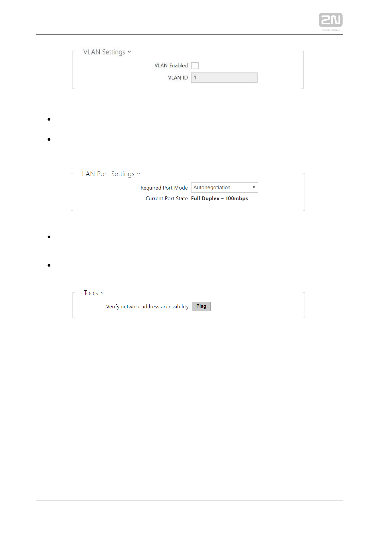
VLAN Enabled – enable the virtual network support (VLAN according to 802.1q).
Remember to set the VLAN ID too.
VLAN ID – choose a VLAN ID from the range of 1–4094. The device shall only
receive packets with the set ID. An incorrect setting may result in a connection
loss and subsequent factory reset.
Required Port Mode – set the LAN port mode to be preferred: Automatic or Half
Duplex – 10 Mbps. The bit rate is reduced to 10 Mbps in case the available LAN
cabling is unreliable for a 100 Mbps traffic.
Current Port State – current LAN port state: Half or Full Duplex – 10 Mbps or 100
Mbps.
Verify the network address accessibility – check the accessibility of a given address in
the LAN via the Ping command like in common operating systems. Press Ping to
display a dialogue for you to enter the IP address/domain name and press Ping to
send the test data to the set address. If the IP address/domain name is invalid, a
warning is displayed and the Ping button remains inactive until the IP address
becomes valid. The dialogue also displays the procedure state and result. Failed
means that either the IP address was unavailable within 10 s or it was impossible to
translate the domain name into an address. If a valid response is received, the
response sending IP address and response waiting time in milliseconds are displayed.
Press Ping again to send another query to the same address.
2N TELEKOMUNIKACE a.s., www.2n.cz 73/134
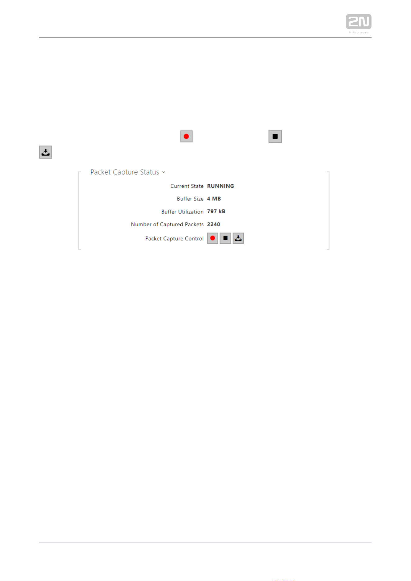
Trace
The Trace tab helps you trigger capturing of incoming and outgoing packets via the 2N
LAN interface. The captured packets are stored in a 4 MB buffer. Indoor Compact
®
When the buffer storage capacity is full, the oldest packets are rewritten
automatically. You are recommended to keep the video stream bit rate below 512
kbps while capturing packets. Press to start capturing, to stop capturing and
to download the captured packet file.
2N TELEKOMUNIKACE a.s., www.2n.cz 74/134
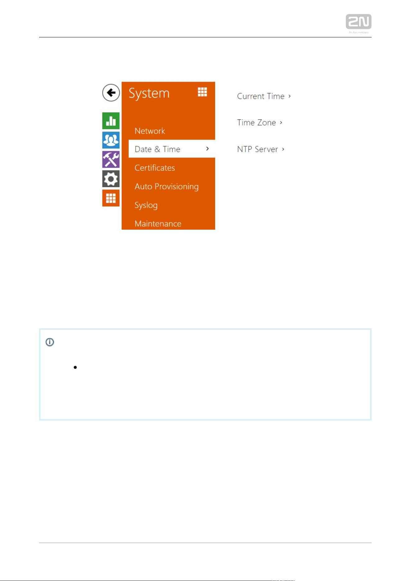
3.2.5.2 Date and Time
2N Indoor Compact
®
is equipped with a real time clock to back up the device for even
a few days in case of power outage. Click to synchronize Synchronize 2N Indoor
®
with your PC time value any time.Compact
Time in can be synchronized with any available SNTP server.2N Indoor Compact
®
Note
A correct date/time value is unnecessary for the basic function of 2N
®
, but crucial for a proper function of time profiles and Indoor Compact
correct event times in variable lists (Syslog, Entered cards, Logs
downloaded via , etc.).HTTP API
In standard operational conditions, the real time circuit accuracy 2N Indoor Compact
®
is ±0.005 %, which may represent an error of up to ±2 minutes per month.
2N TELEKOMUNIKACE a.s., www.2n.cz 75/134
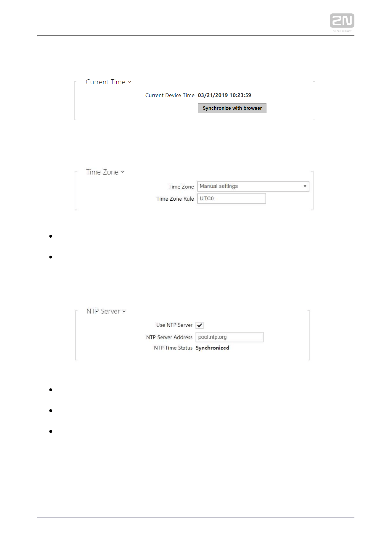
List of Parameters
Synchronize with browser – click the button to synchronize the device time with your
current PC time value.
Time Zone – set the time zone for your installation site. to define time shifts and
summer/winter time transitions.
Time Zone Rule – set the time zone rule manually if your device is installed on a
site that is not included in the Time Zone list. The Time Zone Rule is applied only
if the Time Zone is set to manually define time shifts and summer/winter
transitions. The time zone rule is only applied if the Time zone parameter is set
to .Manual settings
Use NTP Server – enable the use of the NTP server for internal time
Synchronization.
NTP Server Address – set the IP address/domain name of the NTP server used
for the device internal time synchronization.
NTP Time Status – display the state of the last local time synchronization
attempt via NTP: Unsynchronized. Synchronized, Error.
2N TELEKOMUNIKACE a.s., www.2n.cz 76/134
1.
a.
b.
c.
d.
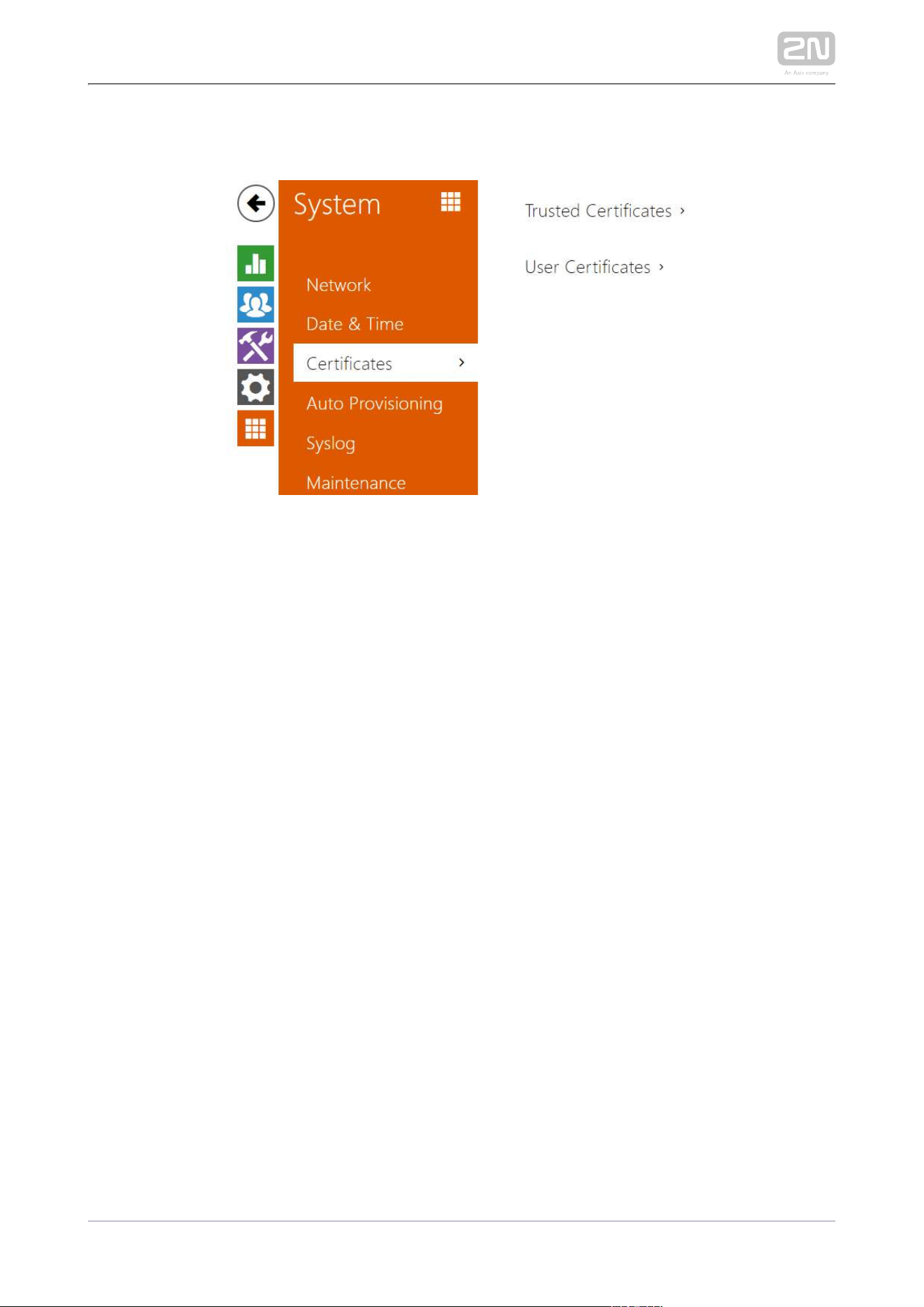
3.2.5.3 Certificates
Some LAN services use the secure TLS protocol for 2N Indoor Compact
®
communication with the other LAN devices. This protocol prevents third parties from
eavesdropping on or modifying call contents. TLS is based on one/two-sided
authentication, which requires certificates and private keys.
2N Indoor Compact
®
services that use TLS:
Web server (HTTPS)
E-mail (SMTP)
802.1x (EAP-TLS)
SIPs
2N Indoor
®
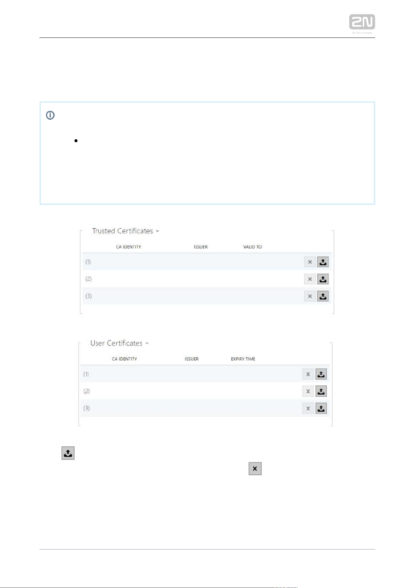
Compact allows you to download up to 3 sets of certificates issued by
certification authorities, which help you authenticate the communicating device, and
also 3 user certificates and private keys for encryption purposes.
Each certificate requiring service can be assigned one certificate set, refer to the Web
, and subsections. The certificates can be shared by multiple Server E-mail Streaming
services.
2N Indoor
®
Compact accepts the DER (ASN1) and PEM certificates.
2N TELEKOMUNIKACE a.s., www.2n.cz 77/134
Once powered up, generates automatically the so-called 2N Indoor
®
Compact Self
and a , which can be used for the and Signed certificate private key Web server E-mail
services without the need to upload a unique certificate and private key.
Note
If you use the
Self Signed certificate for encryption, the 2N Indoor
®
web server - browser communication is secure, but the Compact
browser notifies you that it cannot authenticate the 2N Indoor
®
Compact
certificate.
Refer to the tables below for the current list of trusted and user certificates:
Click to upload a certificate saved on your PC. Select the certificate (or private
key) file in a dialogue window and click . Press to remove a certificate from Upload
.2N Indoor Compact
®

2N TELEKOMUNIKACE a.s., www.2n.cz 78/134
Caution
Note that a certificate with a private RSA key longer than 2048 bits may
be rejected and the following message will be displayed:
The private key file/password was not accepted by the device!
For certificates based on elliptic curves use the secp256r1 (aka
prime256v1 aka NIST P-256) and secp384r1 (aka NIST P-384) curves
only.
2N TELEKOMUNIKACE a.s., www.2n.cz 79/134
3.2.5.4 Auto Provisioning
2N Indoor Compact
®
helps you update firmware and configuration manually or
automatically from a selected TFTP/HTTP server storage according to predefined
rules.
The TFTP and HTTP server addresses can be configured manually. 2N Indoor
®
supports automatic address identification via the local DHCP server (Option Compact
66).
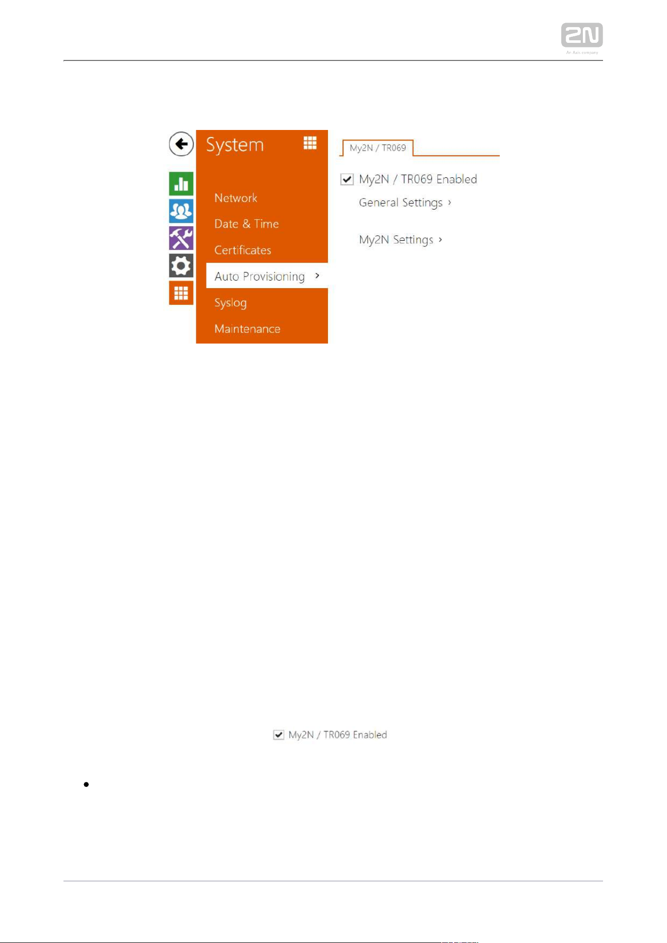
My2N / TR069
Use this tab to enable and configure remote device management via the TR-069
protocol. TR-069 helps you reliably configure the device parameters, update and back
up configuration and/or upgrade device firmware.
The TR-069 protocol is utilized by the My2N cloud service. Make sure that TR-069 is
enabled and Active profile set to My2N to make the device work with My2N properly.
Only then the device will be able to log in to My2N periodically for configuration.
This function helps you connect the device to your ACS (Auto Configuration Server).
In this case, the connection to My2N will be disabled in the device.
My2N / TR069 Enabled – enable connection to My2N or another ACS server.
2N TELEKOMUNIKACE a.s., www.2n.cz 80/134
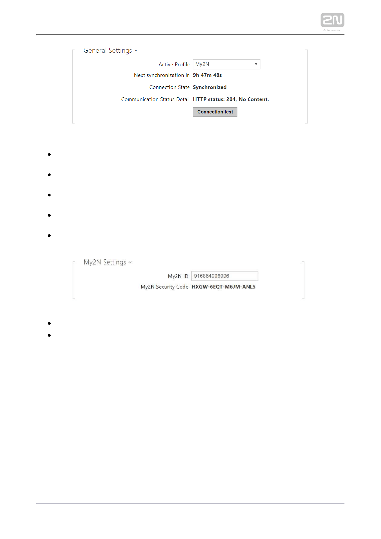
Active Profile – select one of the pre-defined profiles (ACS), or choose a setting
of your own and configure the ACS connection manually.
Next synchronization in – display the time period in which the device shall
contact a remote ACS.
Connection Status – display the current ACS connection state or error state
description if necessary.
Communication Status Detail – server communication error code or HTTP status
code.
Connection test – test the TR069 connection according to the set profile, see
the Active profile. The test result is displayed in the Connection status.
My2N ID – unique identifier of the company created via the My2N portal.
– device code for adding to My2N.My2N Security Code
2N TELEKOMUNIKACE a.s., www.2n.cz 81/134
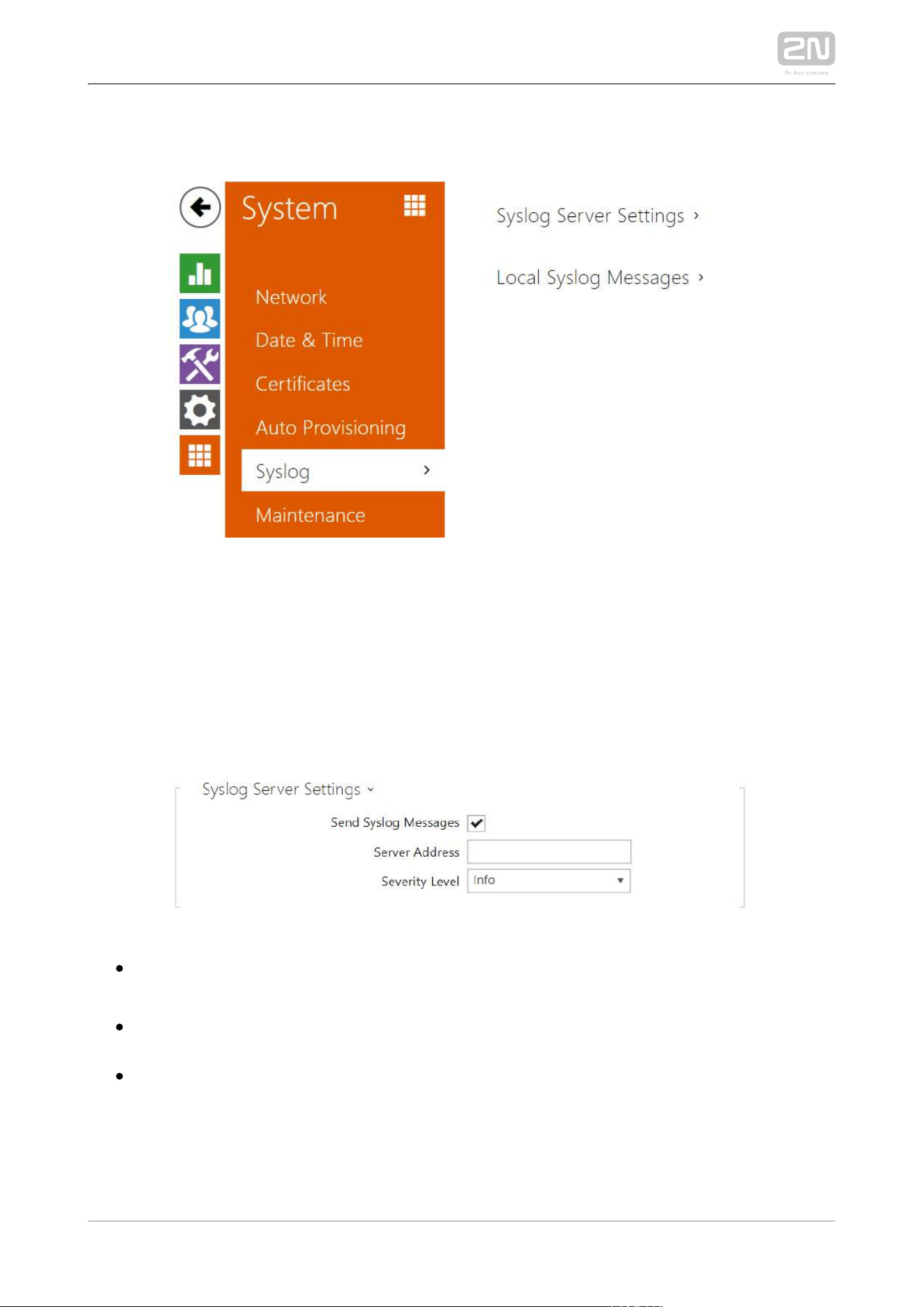
3.2.5.5 Syslog
2N Indoor Compact
®
allows you to send syslog messages including relevant device
state and process information to a syslog server for recording and further analysis or
auditing of the device observed. It is unnecessary to configure this service for
common operations.
List of Parameters
Send Syslog Messages – enable sending of syslog messages to the Syslog server.
Make sure that the server address is valid.
Server Address – IP/MAC address of the server on which the syslog recording
application is running.
Severity Level – set the severity level of the messages to be sent. Debug 1–3
level setting is only recommended to facilitate troubleshooting for the Technical
Support department.
2N TELEKOMUNIKACE a.s., www.2n.cz 82/134
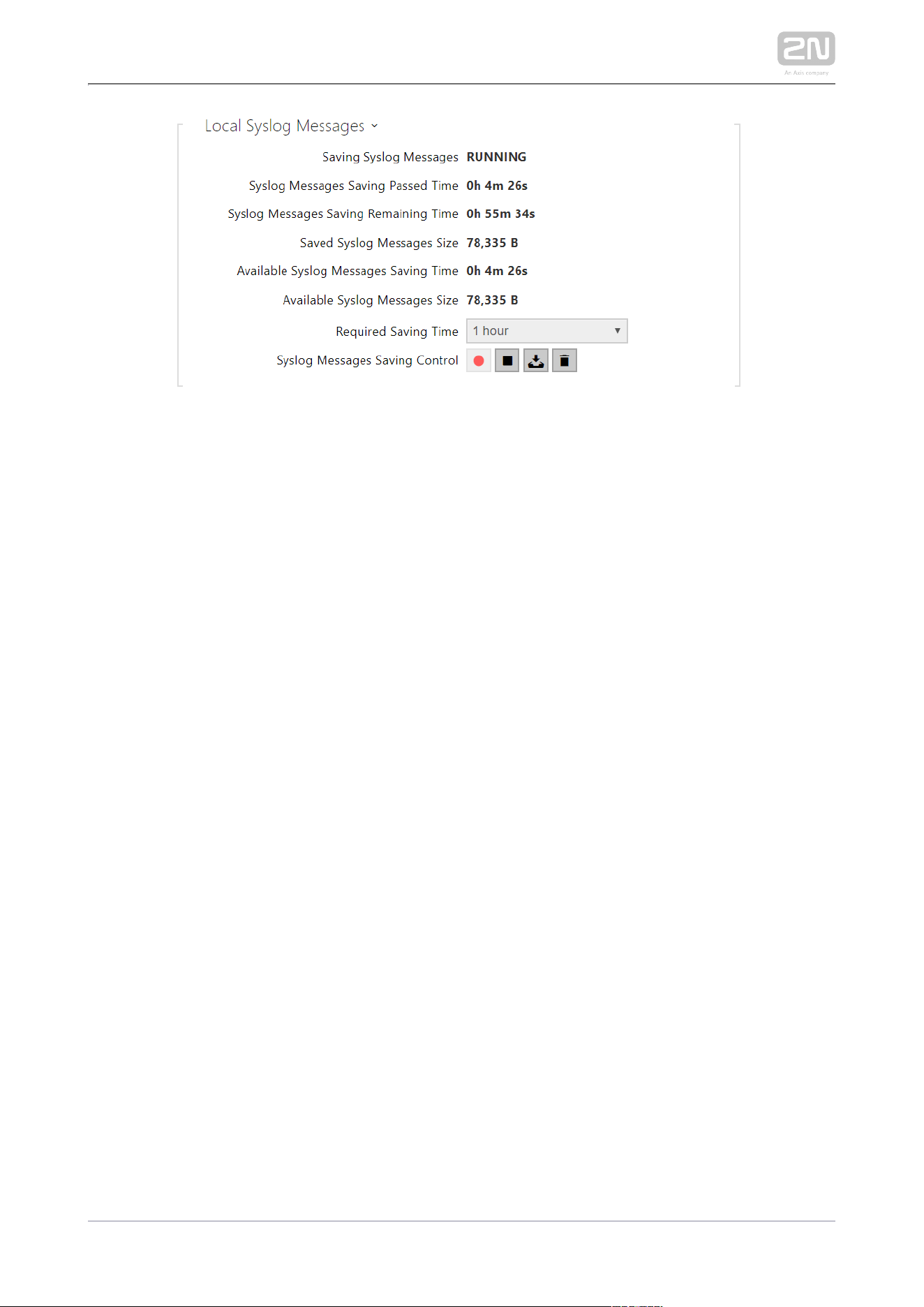
General overview of local syslog messages.
2N TELEKOMUNIKACE a.s., www.2n.cz 83/134
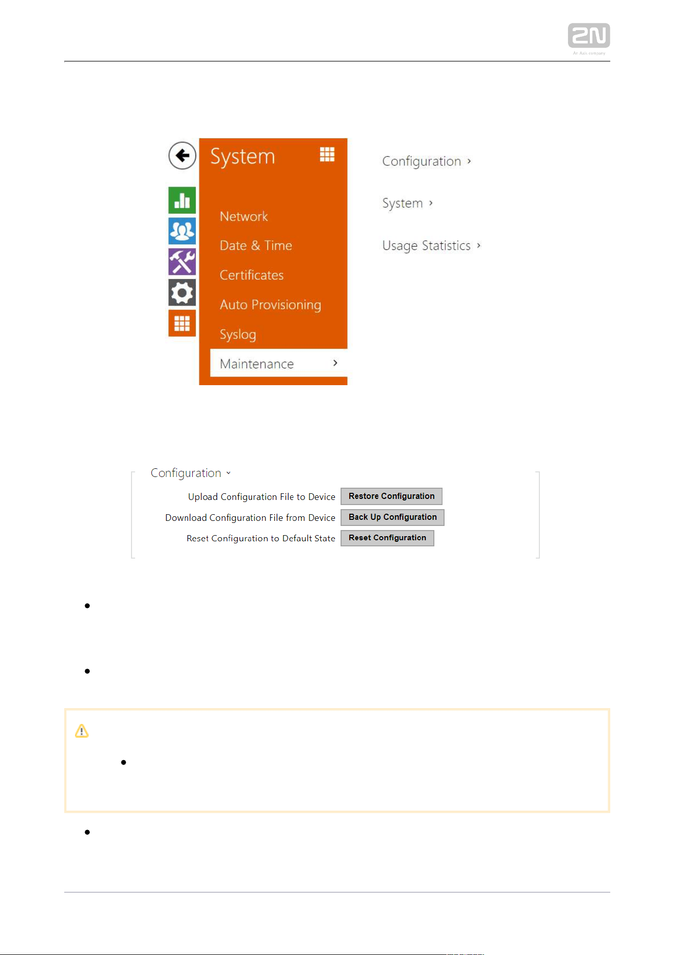
3.2.5.6 Maintenance
This menu helps you maintain the device configuration and firmware. You can back up
and restore all the parameters, upgrade firmware and/or factory reset the device.
Restore Configuration – restore configuration from a previous backup. Press the
button to display a dialogue window to select a configuration file and upload it
to the device. Before uploading choose whether or not the LAN settings and SIP
PBX connection settings are to be applied.
Backup Configuration – back up the complete current device configuration.
Press the button to download the configuration file to your PC.
Caution
As the configuration may include delicate information, such as user
phone numbers and access passwords, handle the file cautiously.
Reset Configuration – reset all the device parameters except for the LAN
parameters. To reset the device completely, use the jumper or press Reset.
2N TELEKOMUNIKACE a.s., www.2n.cz 84/134
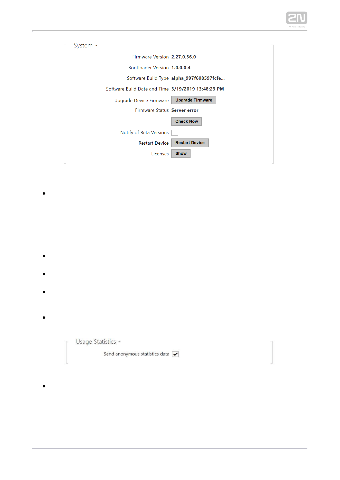
Upgrade FirmwareDevice – upload a new firmware version to the device. Press
the button to display a dialogue window to select the proper firmware file. Once
the firmware is uploaded, the device is restarted automatically and becomes
fully operational with a new firmware version. The whole upgrading process
takes less than one minute. Download the current firmware version for your
device from Firmware upgrade does not affect configuration. The www.2n.cz
device checks the firmware file and prevents you from uploading an incorrect or
corrupt file.
Firmware Status – check online if a later firmware version is available. If so, the
downloading option is offered followed by automatic upgrade.
Notify of Beta Versions – enable monitoring and downloading of the latest
firmware beta version.
Restart Device – restart the device. The process takes about 30 s. Once restart is
completed and the device is assigned its IP address, the login window will be
displayed automatically.
Licenses – click Show to open a dialogue window including a list of used licenses
and third-party libraries. It also includes a EULA link.
Send anonymous statistics data – enable sending of anonymous statistic data on
device usage to the manufacturer. No such delicate information as passwords,
access codes or phone numbers are included. This information helps 2N
TELEKOMUNIKACE a.s. improve the software quality, reliability and
performance. You can participate in this voluntarily and cancel your statistic
data deliveries any time.

2N TELEKOMUNIKACE a.s., www.2n.cz 85/134
4. Device Control via Display
The backlit MENU buttons to the right and left help you control the device using the
display. The MENU buttons are used for shifting and confirming functions in the
selected display menu. In general, the MENU buttons to the right shift items up and
down in the selected menu. The left-hand lower button confirms your selection and
the left-hand upper button goes back by one step with every press or returns to the
home page.
Refer to the following subsections for more configuration details.
4.1 Directory
4.2 Call Log
4.3 Do Not Disturb Mode
4.4 Settings
2N TELEKOMUNIKACE a.s., www.2n.cz 86/134
1.
2.
3.
4.
MENU buttons
Lock button
Call end button
Call receiving button
Icons used on the display
Icon Description
Directory
DND mode
Device configuration
Call log
2N TELEKOMUNIKACE a.s., www.2n.cz 87/134
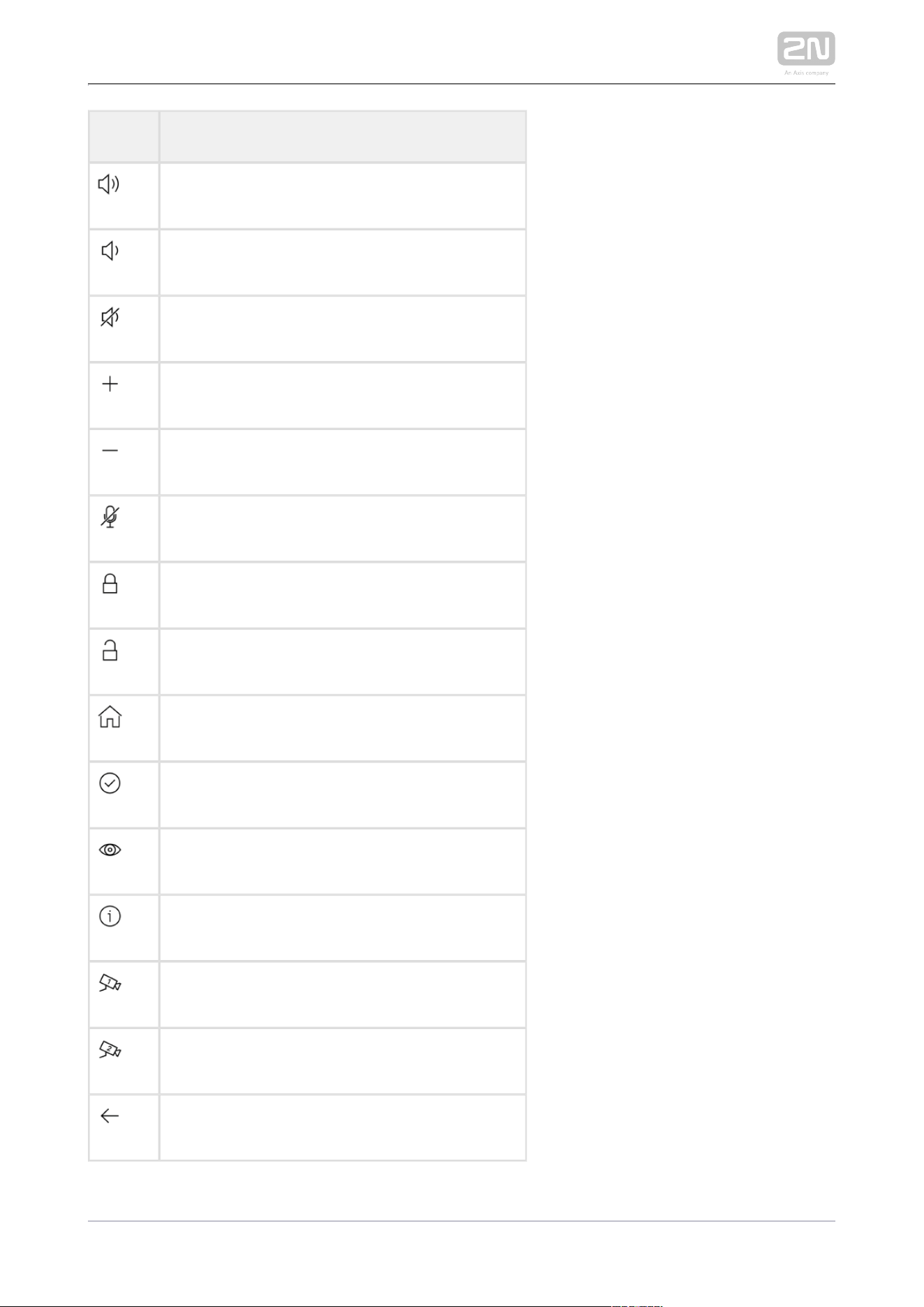
Icon Description
Incoming call ringtone volume up
Incoming call ringtone volume down
Incoming call ringtone volume mute
Value up
Value down
Microphone mute in call
Locked, screen lock
Unlocked, screen lock activated/deactivated
Return to Home page
Confirmation
Device detail in Directory
Call info
Camera 1
Camera 2
Back

2N TELEKOMUNIKACE a.s., www.2n.cz 88/134
Icon Description
Move up
Move down
2N TELEKOMUNIKACE a.s., www.2n.cz 89/134
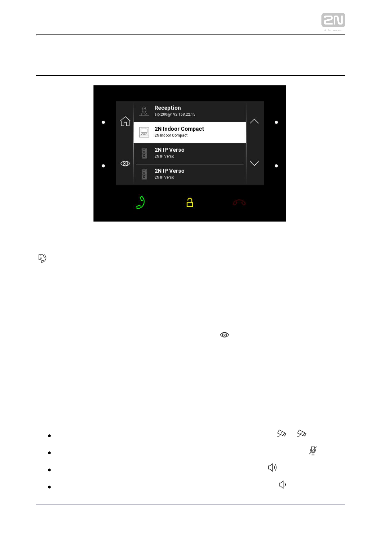
4.1 Directory
Press the left-hand upper button at the icon
to display the Directory list. The menu provides a list of destinations that can be
called. The destinations include their names and the device type they are equipped
with. The destinations that allow for some actions (calls) are white-highlighted. The
other destinations are gray.
Use the backlit right-hand upper button and lower MENU button to move across the
Directory. Press the left-hand lower button at the icon to display the user detail.
The detail includes the device type, name and icon.
Press the call receiving button to start a call to the selected device or user. Click the
lock button to open the door during an incoming/outgoing call for the selected
device.
When the intercom camera view is displayed on during the call, 2N Indoor Compact
®
you can choose any of the following actions:
Switch camera using the left-hand upper MENU button at the / icon.
Mute microphone in call using the left-hand lower MENU button at the icon.
Volume up using the right-hand upper MENU button at the icon.
Volume down using the right-hand lower MENU button at the icon.
2N TELEKOMUNIKACE a.s., www.2n.cz 90/134
Open door using the door lock button .
End call using the call end button.
Caution
The camera switching function is only displayed if it has been activated
and properly configured in the intercom.
Set the Directory via the web interface in the Directory / Device section. You can add
a device manually, by clicking on the device adding icon or automatically by
clicking the registered device searching icon . Select the device in the list to add it
automatically to the Directory list. The values are completed in the basic settings.
With manual addition of a device/user to the Directory, the basic parameters are not
completed automatically but have to be added manually. Make sure to complete the
proper parameter in the Display section to display the CLIP. This helps the user
choose and call any device displayed; refer to for more details.3.2.2 Directory
2N TELEKOMUNIKACE a.s., www.2n.cz 91/134
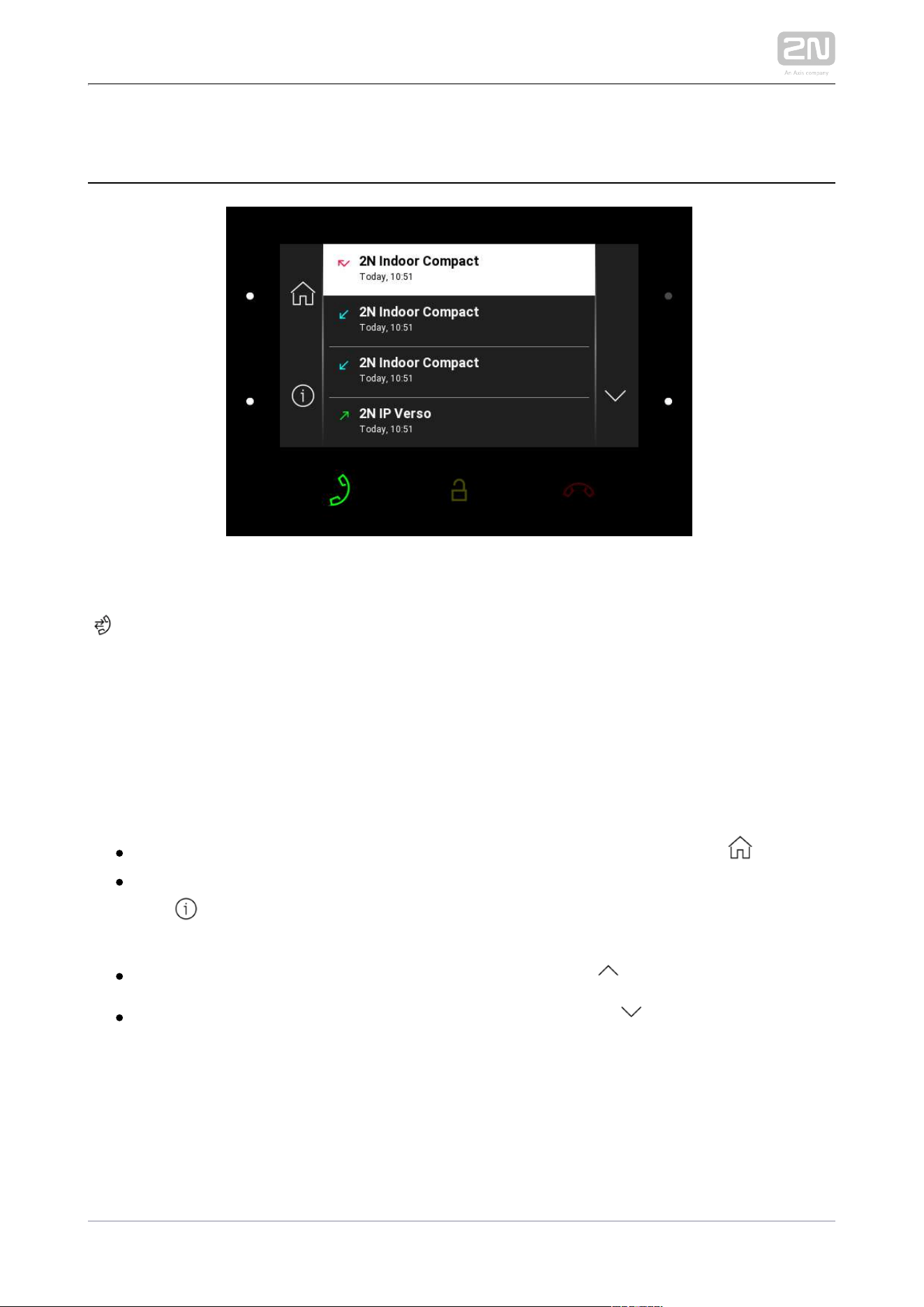
4.2 Call Log
Press the left-hand lower button at the
icon to display the Call log. The menu provides a list of all accomplished calls including
date, time, status (ougoing/incoming/missed) and information on from/to which
destination the call was made. The destinations that allow for some actions are white-
highlighted; the other ones are gray. The maximum call count is 20.
You can choose any of the following actions from the call log:2N Indoor Compact
®
Return to Home page using the left-hand upper MENU button at the icon.
Show detail of the accomplished call using the left-hand lower MENU button at
the detail icon. This displays an image from a camera if available including
the caller's ID and call time.
Move up the list using the upper MENU button at the icon.
Move down the list using the lower MENU button at the icon.

2N TELEKOMUNIKACE a.s., www.2n.cz 92/134
Caution
The device restart results in a deletion of the call log.
2N TELEKOMUNIKACE a.s., www.2n.cz 93/134
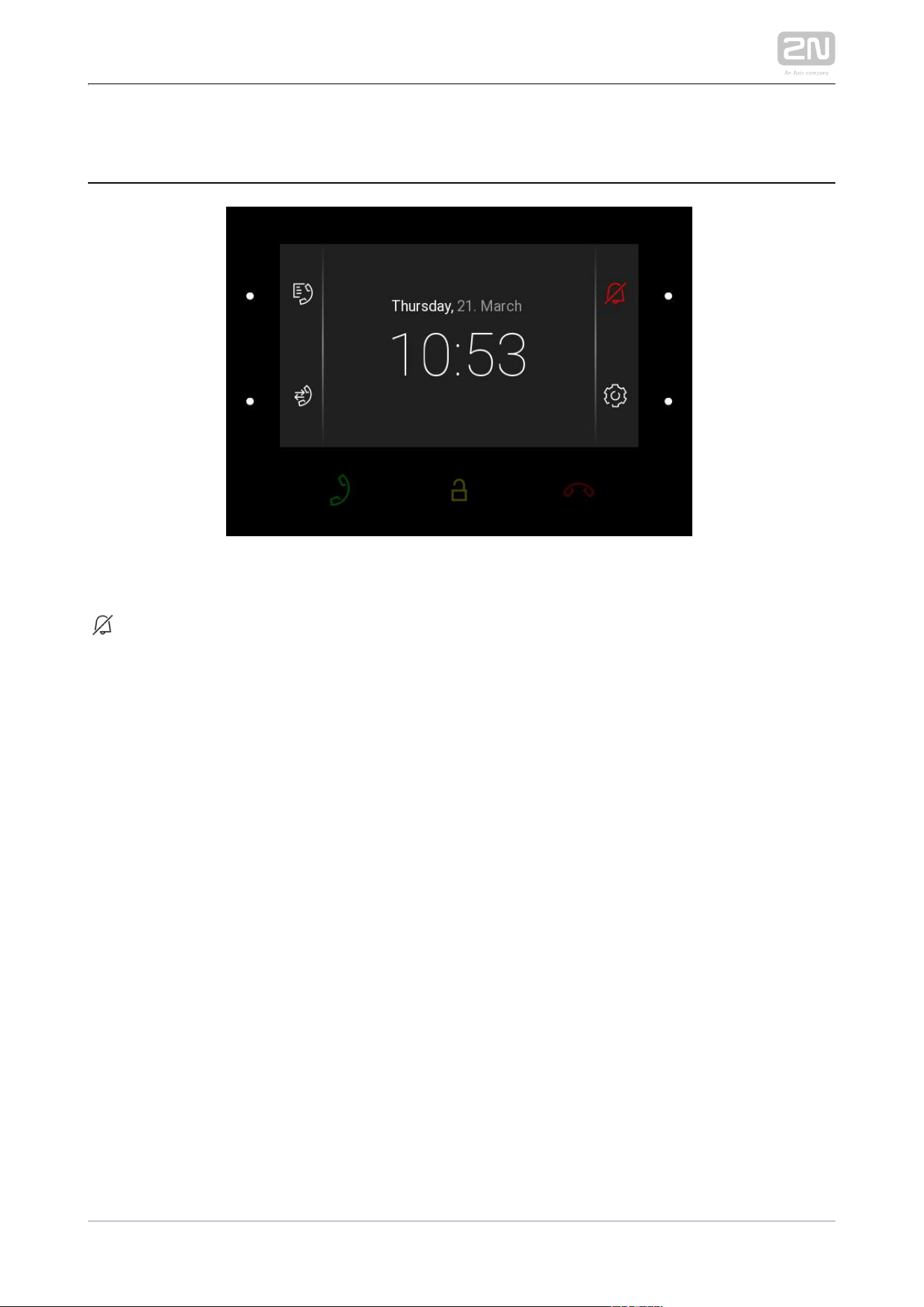
4.3 Do Not Disturb Mode
Press the right-hand upper MENU button at the
icon to activate/deactivate the DND mode. When DND is active, the device is at relax
and the icon is red backlit. The device does not play the selected ringtone to signal an
incoming call. The display shows the camera view if available, CLIP and Incoming call
message.
2N TELEKOMUNIKACE a.s., www.2n.cz 94/134
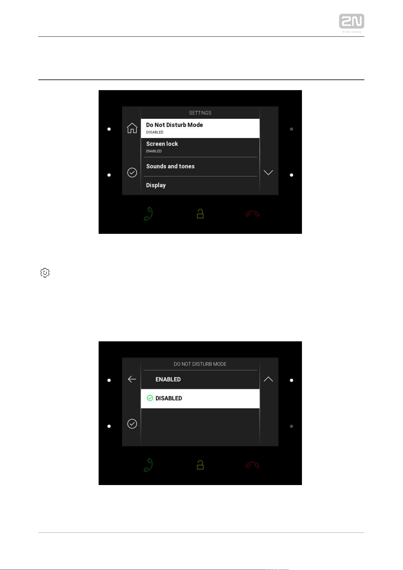
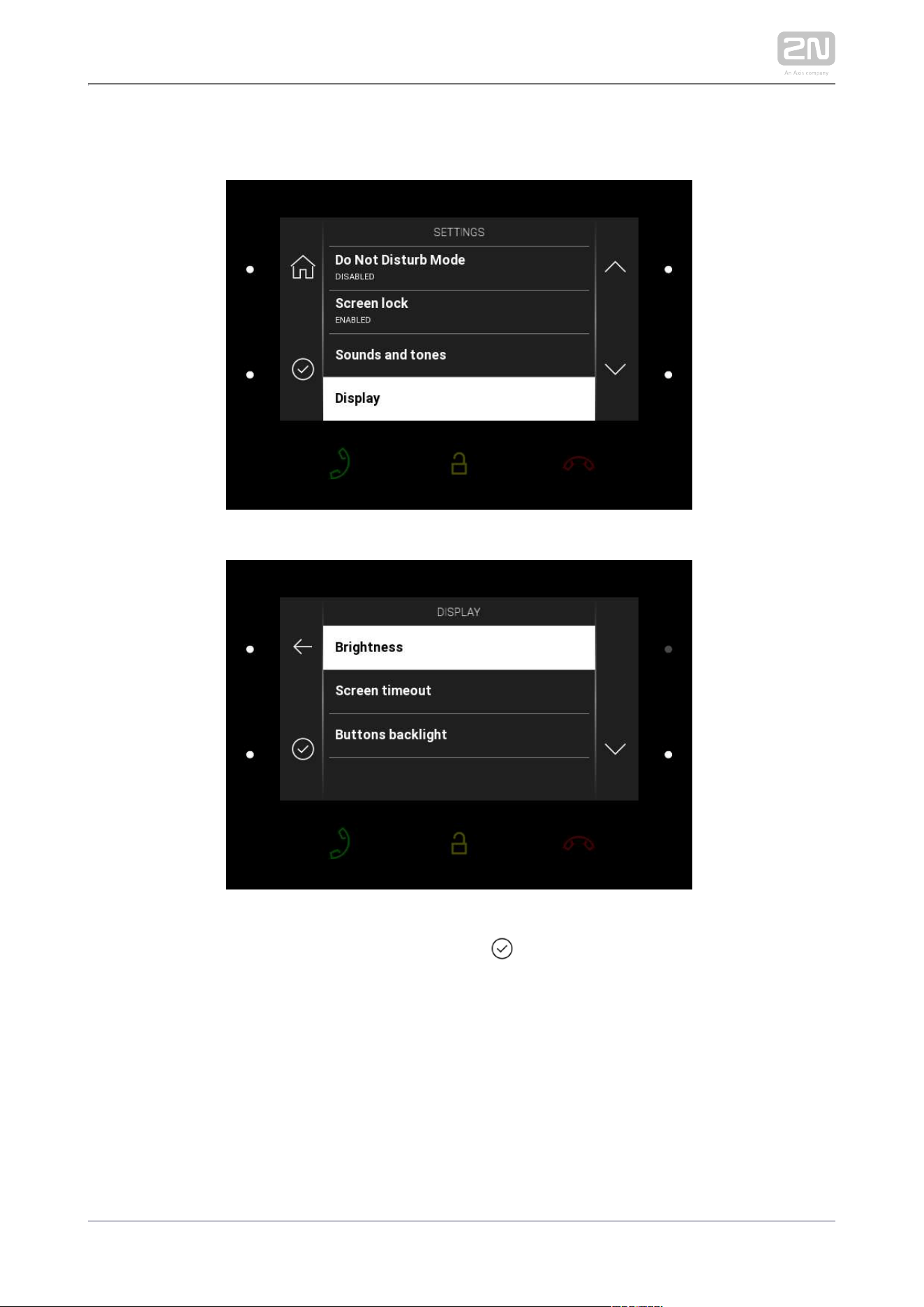
4.4 Settings
Press the right-hand lower button at the icon
to display the Device settings. Here set the DND mode, screen lock, device sounds and
tones and display/system properties.
Do Not Disturb Mode
2N TELEKOMUNIKACE a.s., www.2n.cz 95/134
Enable/disable the DND mode using the left-hand lower button. With DND on, the
icon
on the home page is red backlit. The device does not play the selected ringtone to
signal an incoming call. The display shows the camera view if available, CLIP and
Incoming call message.
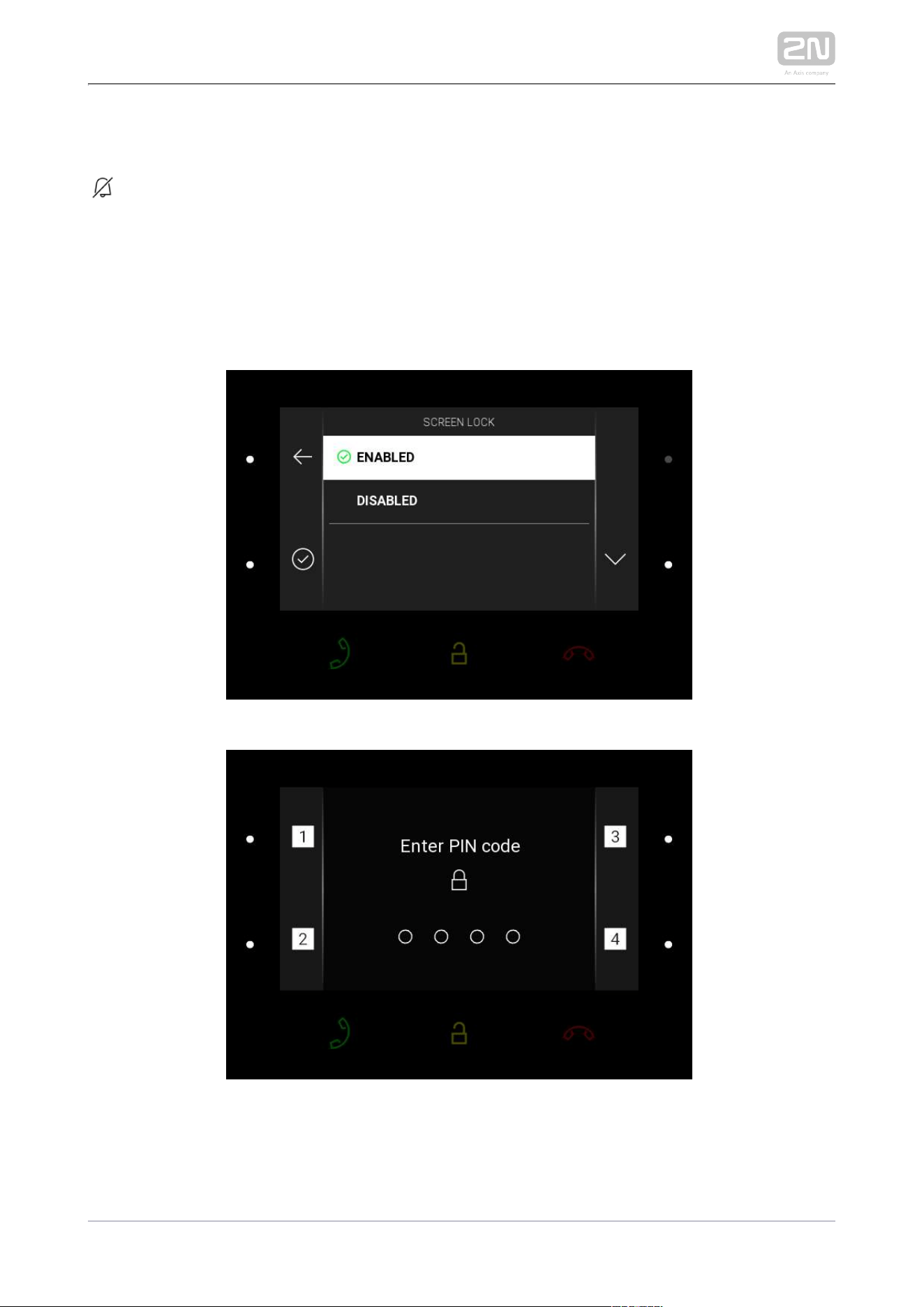
Screen Lock
2N TELEKOMUNIKACE a.s., www.2n.cz 96/134
Enable/disable the screen lock (parental lock) using the left-hand lower button. Enter
the PIN code to enable the screen lock. Enter the same PIN code to disable the screen
lock.
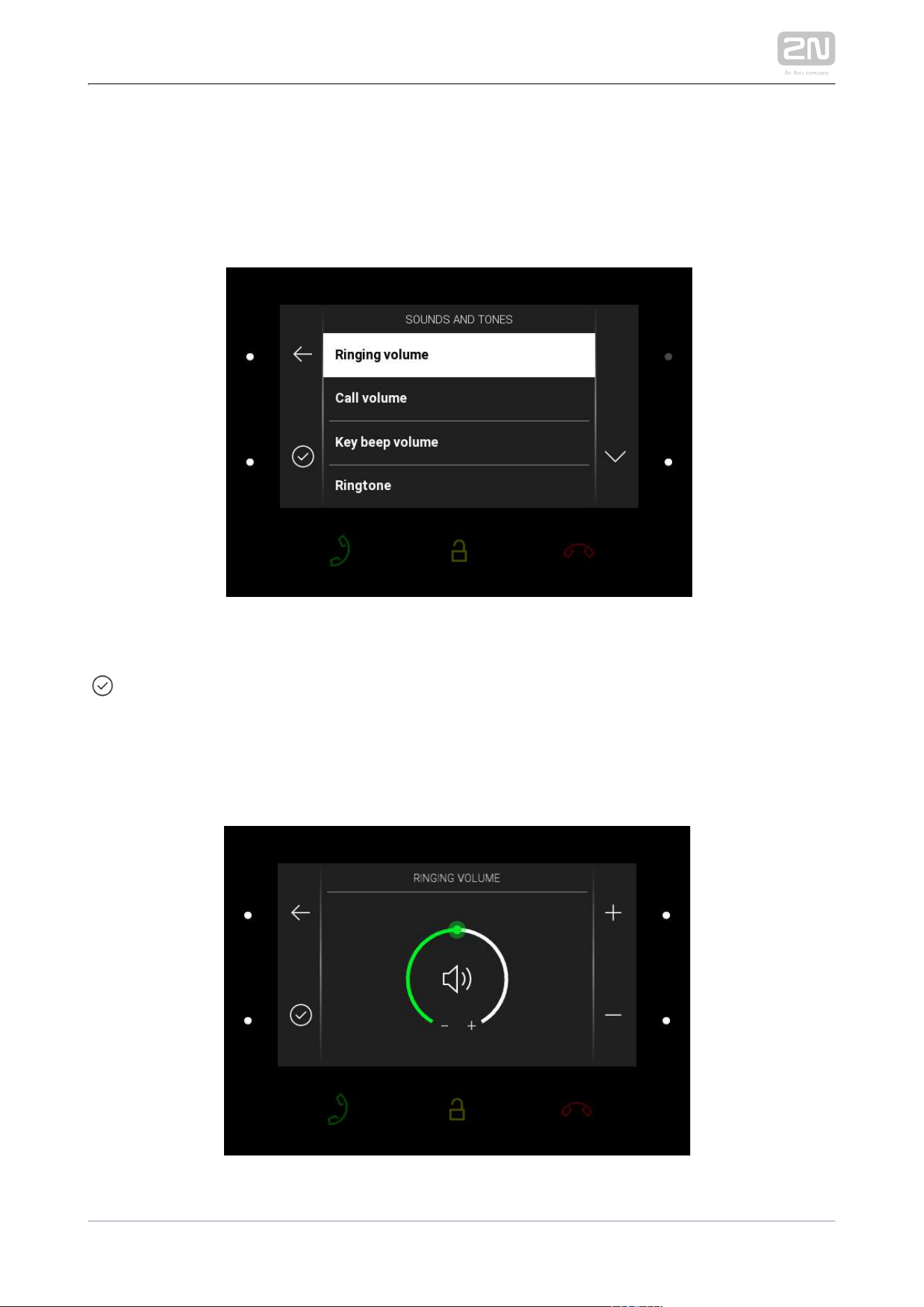
Sounds and Tones
Press the right-hand lower button at the icon
to display the Sounds and Tones. Here set the ringing/call volume and select the
ringtone and door bell ringtone.
Ringing volume
2N TELEKOMUNIKACE a.s., www.2n.cz 97/134
Press the right-hand upper/lower button to increase/decrease the ringing volume.
Press the left-hand lower button to confirm the volume level selected. The change will
not be saved unless confirmed.
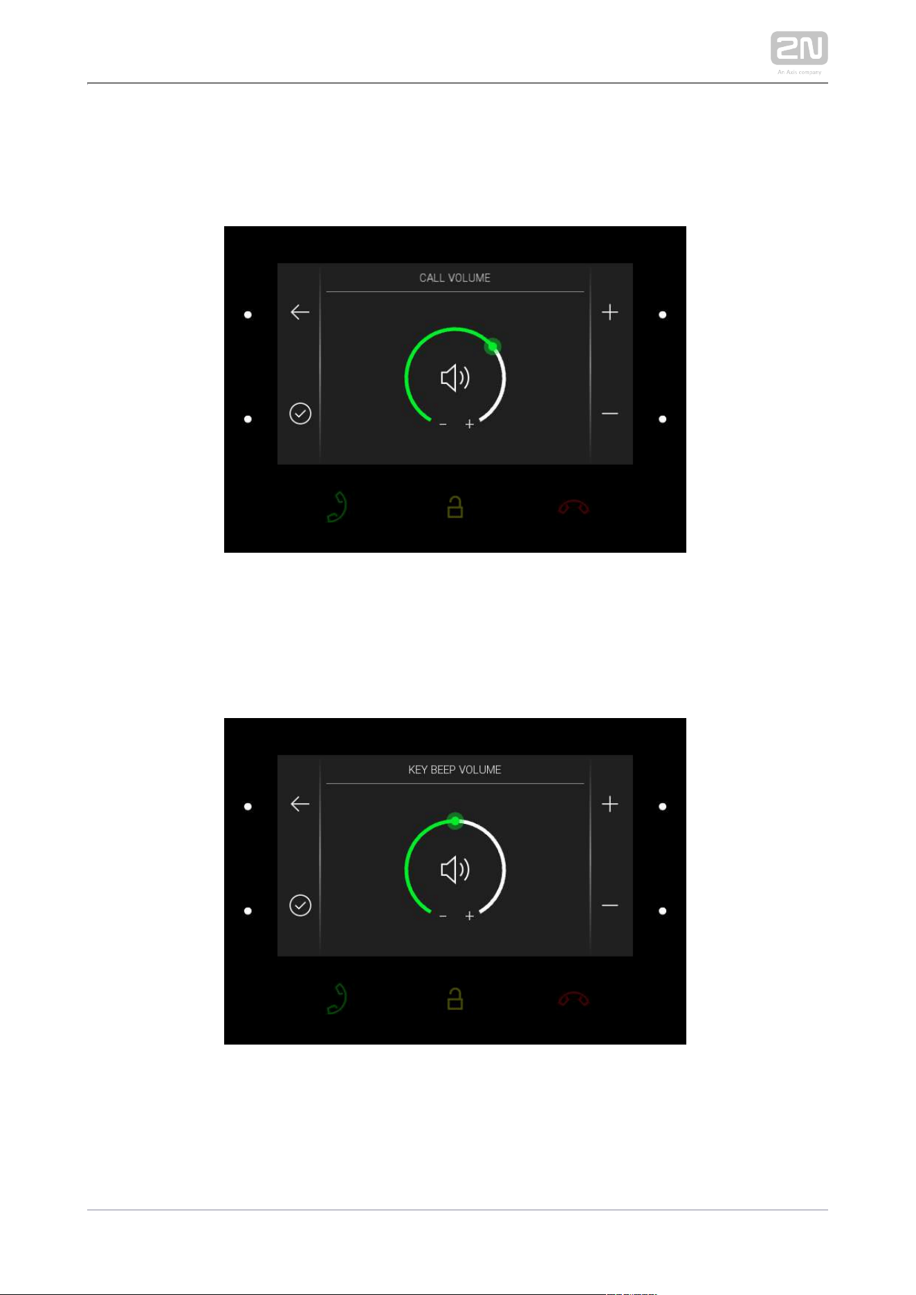
Call volume
Press the right-hand upper/lower button to increase/decrease the call volume. Press
the left-hand lower button to confirm the call volume level selected. The change will
not be saved unless confirmed.
Key Beep Volume
Press the right-hand upper/lower button to increase/decrease the key beep volume.
Press the left-hand lower button to confirm the key beep volume level selected. The
change will not be saved unless confirmed.
2N TELEKOMUNIKACE a.s., www.2n.cz 98/134
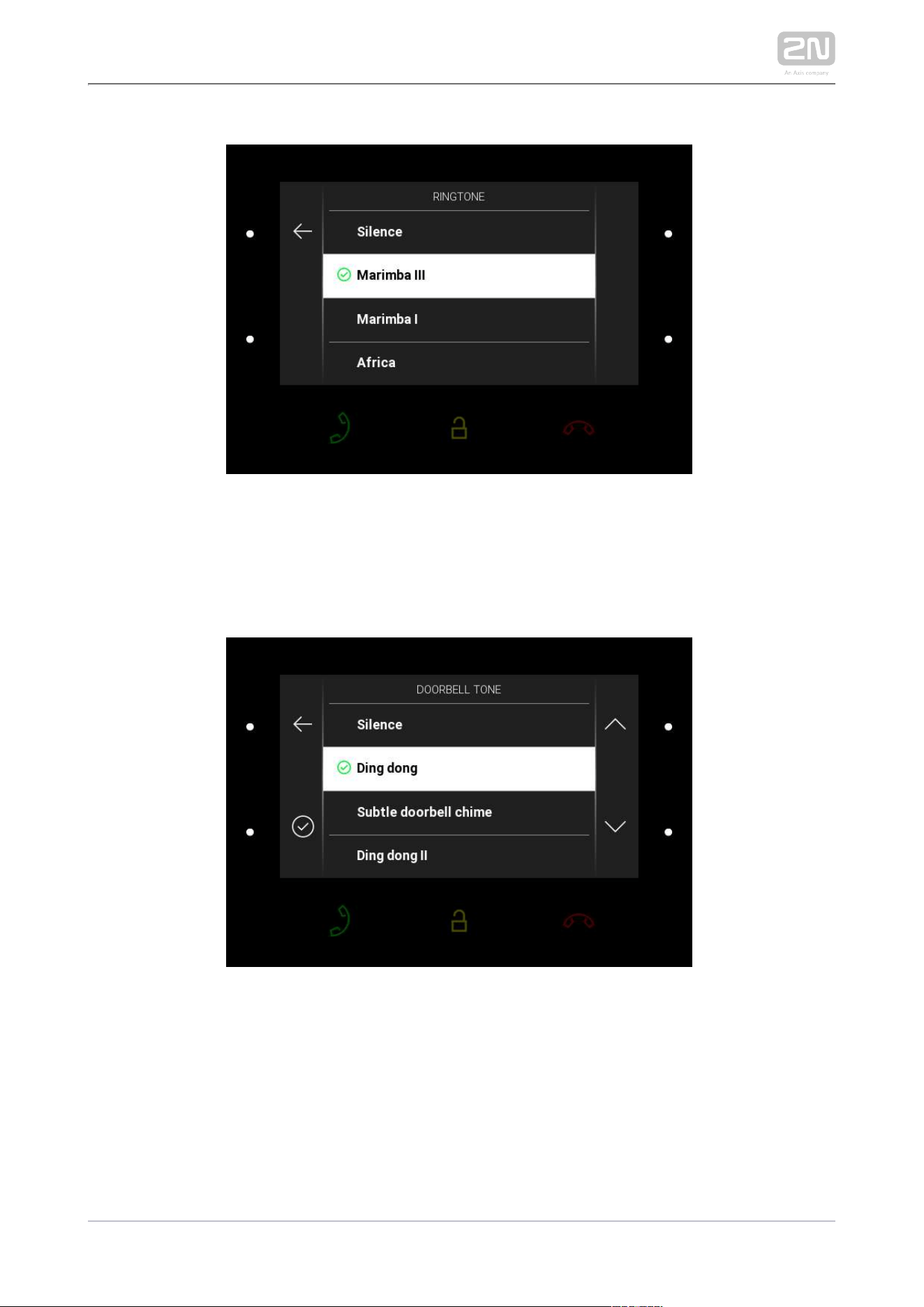
Ringtone
Press the right-hand upper/lower button to move up/down the ringtone list. Press the
left-hand lower button to confirm the ringtone selected. The change will not be saved
unless confirmed.
Doorbell ringtone
Press the right-hand upper/lower button to move up/down the doorbell ringtone list.
Press the left-hand lower button to confirm the ringtone selected. The change will not
be saved unless confirmed.
2N TELEKOMUNIKACE a.s., www.2n.cz 99/134
Display
Press the right-hand lower button at the icon to display the Display section. Here
set the display brightness, idle timeout and button backlight.
2N TELEKOMUNIKACE a.s., www.2n.cz 100/134
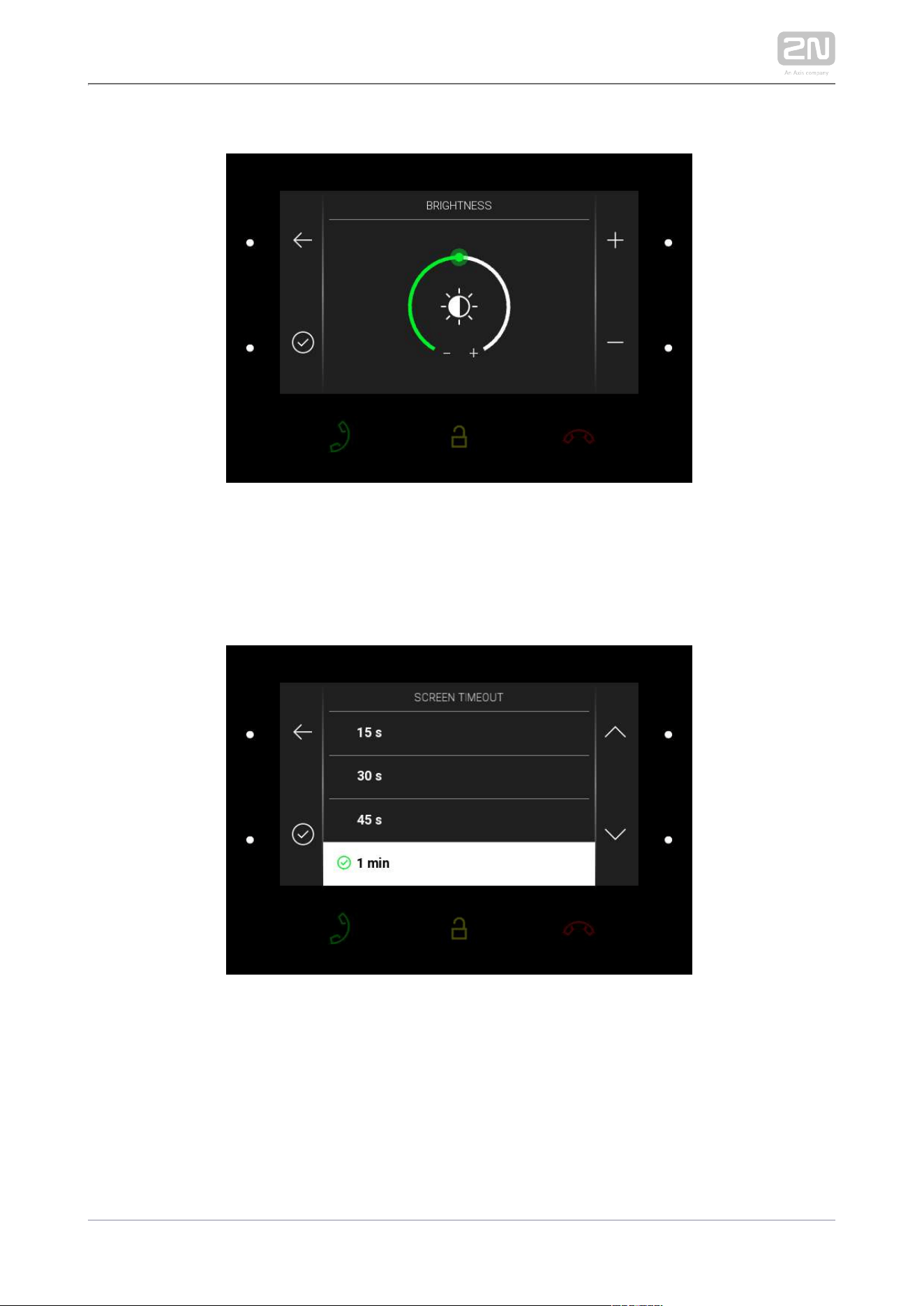
Brightness
Press the right-hand upper/lower button to increase/decrease the display brightness.
Press the left-hand lower button to confirm the brightness level selected. The change
will not be saved unless confirmed.
Screen timeout
Set the maximum idle time (i.e. when the user does not control the device) after which
the sleep mode is switched on automatically. Press the right-hand upper/lower button
to move up/down the time value list. The change will not be saved unless confirmed.
2N TELEKOMUNIKACE a.s., www.2n.cz 101/134
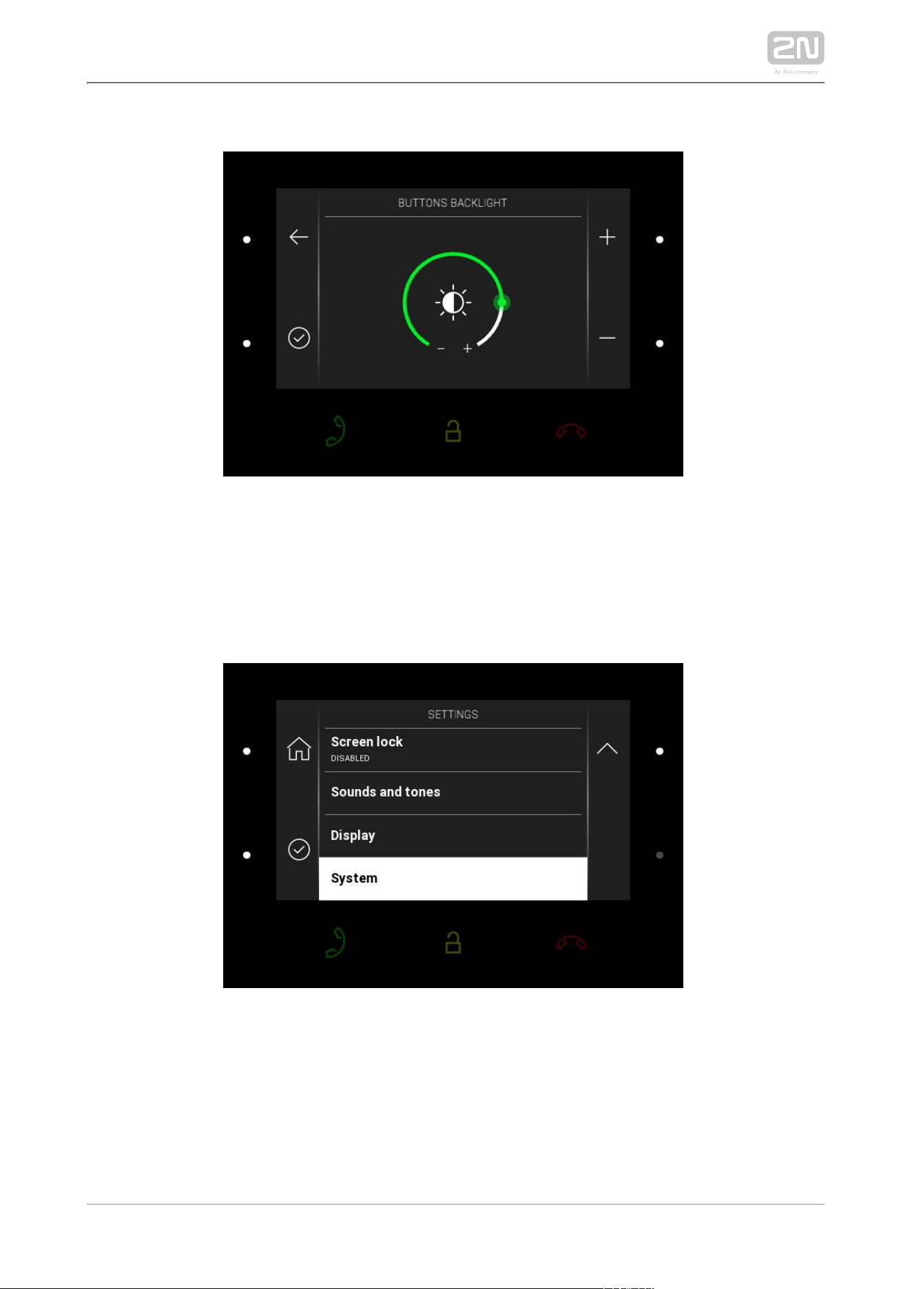
Button backlight
Press the right-hand upper/lower button to increase/decrease the button backlight.
Press the left-hand lower button to confirm the backlight level selected. The change
will not be saved unless confirmed.
System
2N TELEKOMUNIKACE a.s., www.2n.cz 102/134
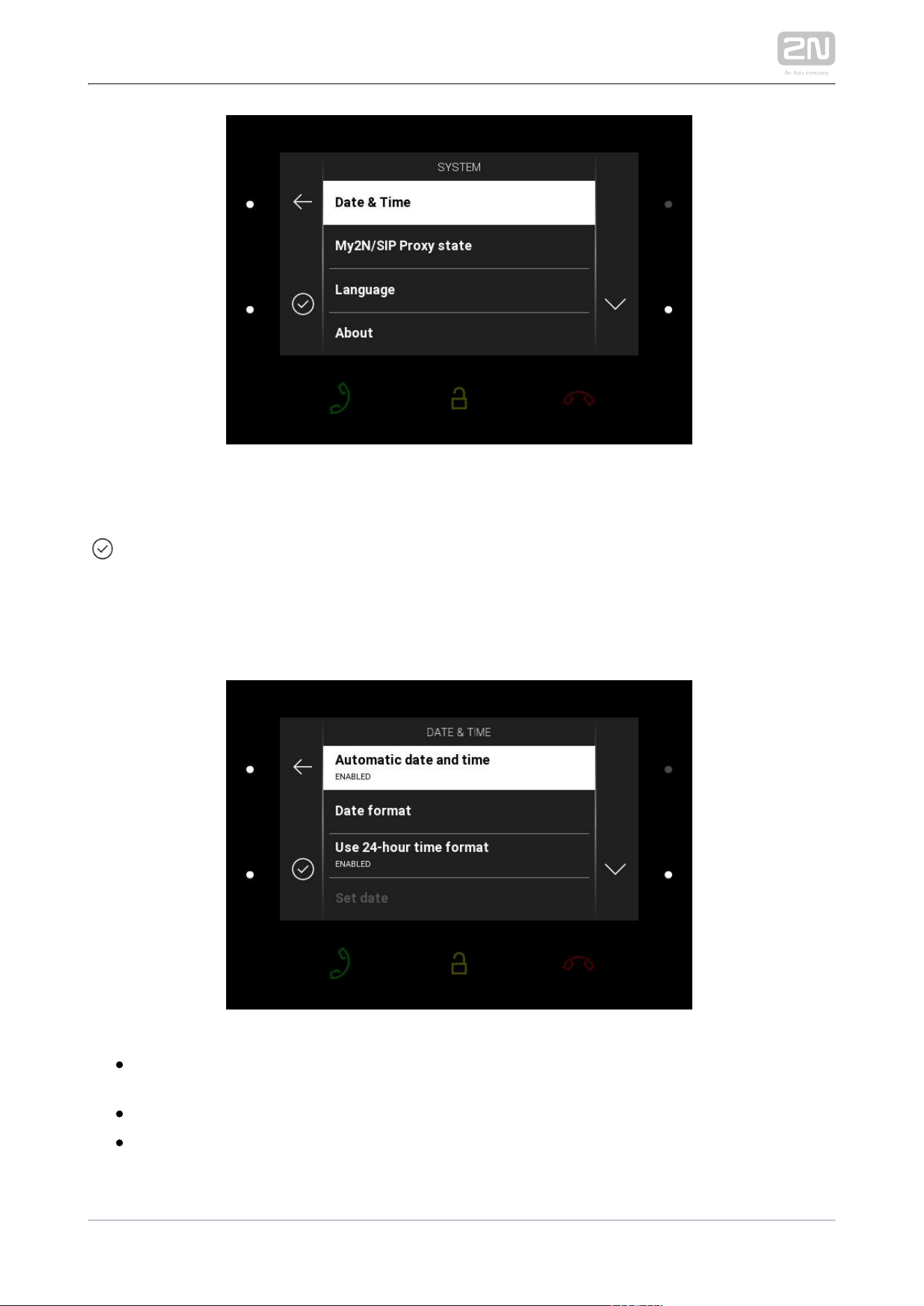
Press the right-hand lower button at the icon
to display the System section. Here set date and time, My2N/SIP Proxy state and
language and get basic information on the device.
Date and time
Automatic date and time – enable the use of the NTP server for automatic
internal time synchronization.
Date format – there are 3 date format options: 12.31.2019, 31.12.2019, 2019.12.31.
Use 24-hour time format – enable/disable the 24hour time format.
2N TELEKOMUNIKACE a.s., www.2n.cz 103/134
Set date – set the date manually unless automatic date synchronization is
enabled.
Time Zone – set the time zone for your installation site to define time shifts and
summer/winter time transitions.
Caution
The change will not be saved unless confirmed.
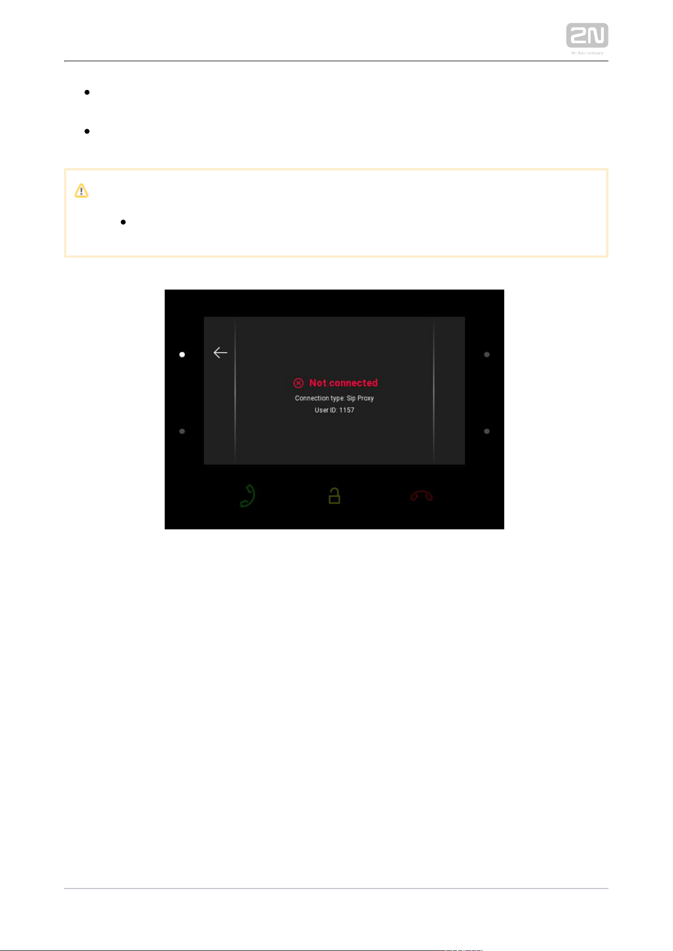
My2N/SIP Proxy State
The My2N/SIP Proxy section displays the current state of the My2N/SIP Proxy
connections.
2N TELEKOMUNIKACE a.s., www.2n.cz 104/134
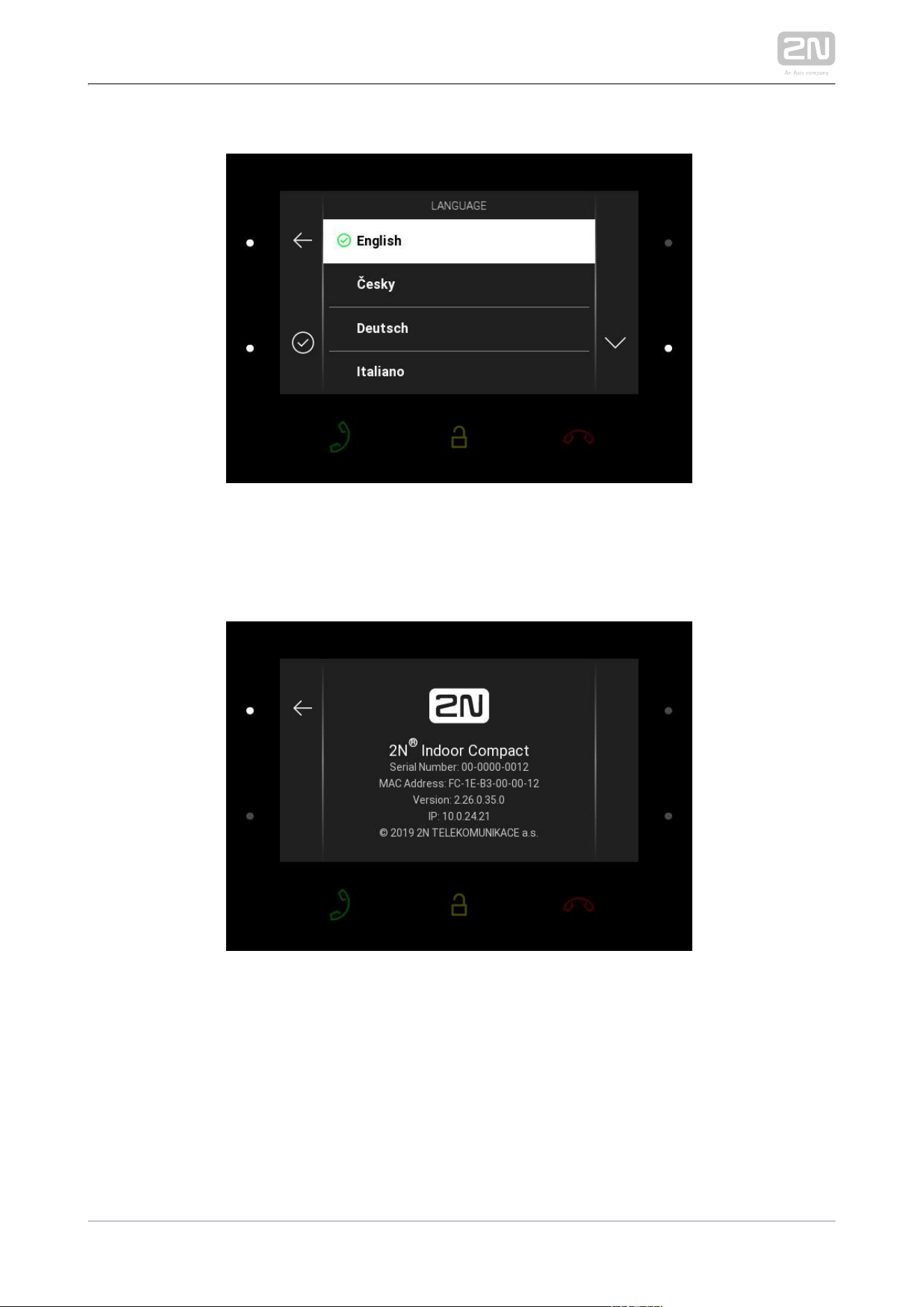
Language
Press the right-hand upper/lower button to move up/down the language list. The
change will not be saved unless confirmed.
About Device
This section provides basic information on the device (serial number, MAC address,
FVW version, IP address).
2N TELEKOMUNIKACE a.s., www.2n.cz 105/134
5. Operational Statuses
This section describes the user scenarios and states that may occur during operation,
including the user options and expected results of actions.
Status and Description User Actions Navigation Actions and Result
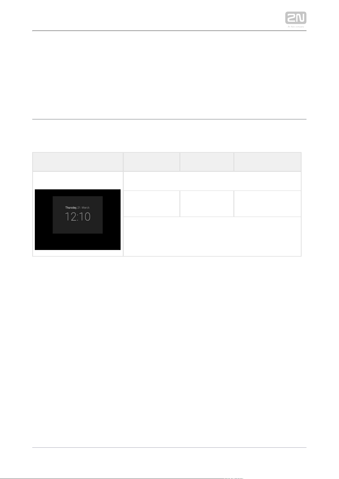
Sleep Mode
No button is backlit and time is displayed on the screen.
End relax mode
Press any button
Home page/parental
lock is displayed.
2N TELEKOMUNIKACE a.s., www.2n.cz 106/134
Status and Description User Actions Navigation Actions and Result
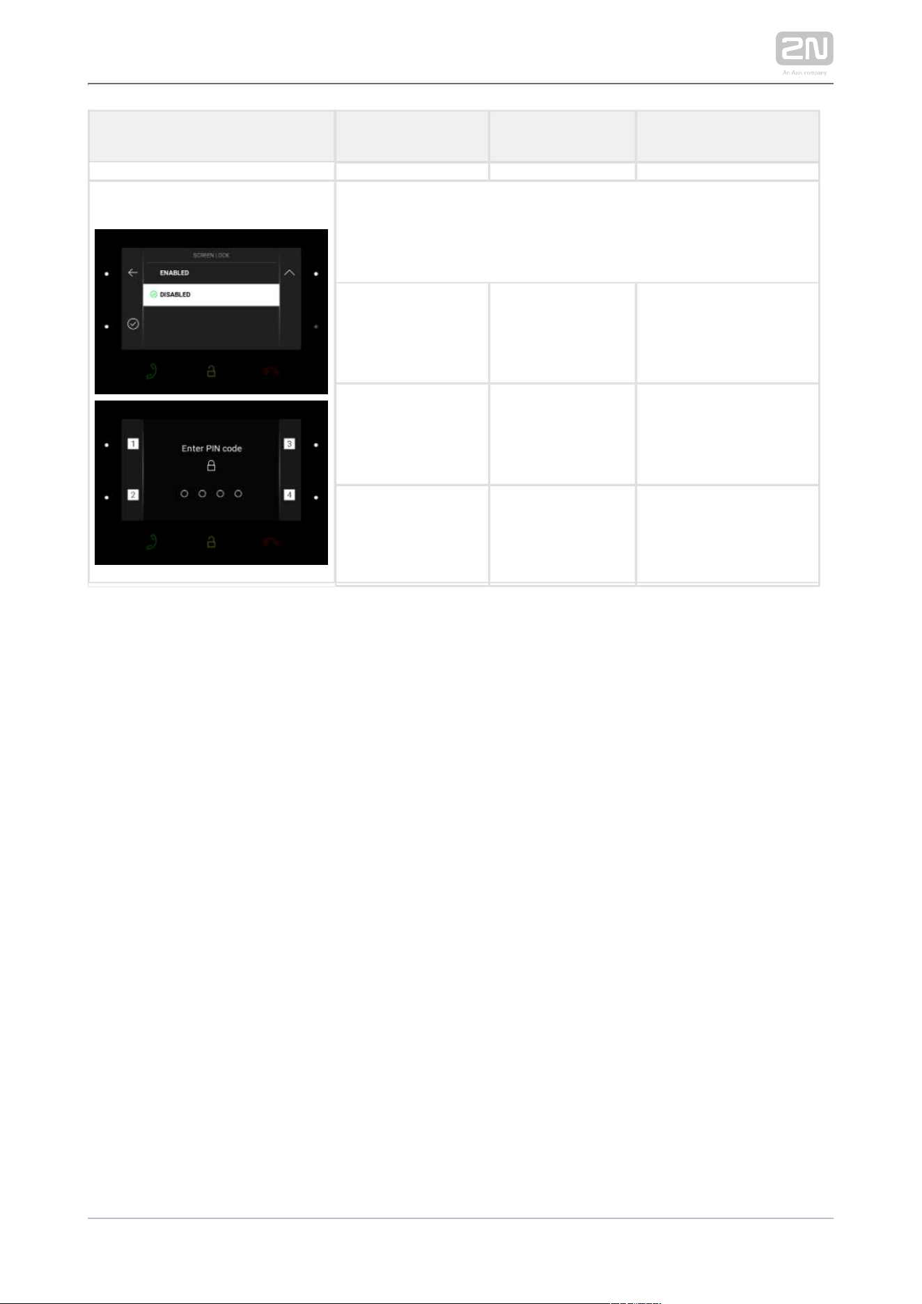
Parental Lock
“Unlock device” and dial pad are displayed. The digit buttons
and red earpiece are backlit to the maximum, the other buttons
are ambiently backlit.
Deactivate
parental lock
Correct PIN
entering
The device is
unlocked, Home page
is displayed.
Enter invalid PIN PIN mistyping The PIN code
reentering command
is displayed.
Quit PIN code
entering
Press the red
earpiece to end
the call
The device gets in the
sleep mode.

2N TELEKOMUNIKACE a.s., www.2n.cz 107/134
Status and Description User Actions Navigation Actions and Result
Home Page
The device is at relax, the side buttons are backlit to the
maximum, the other buttons are ambiently backlit.
Display Directory Press the left-
hand upper
button at the
icon
The list of all available
devices is displayed.
Display Call log Press the left-
hand lower
button at the
icon
The list of all
accomplished calls is
displayed.
Activate DND
mode
Press the right-
hand upper
button at the
icon
DND is activated and
the activation
message is displayed.
Display Settings
Press the right-
hand lower
button at the
icon
The Settings section is
displayed.
2N TELEKOMUNIKACE a.s., www.2n.cz 108/134
Status and Description User Actions Navigation Actions and Result
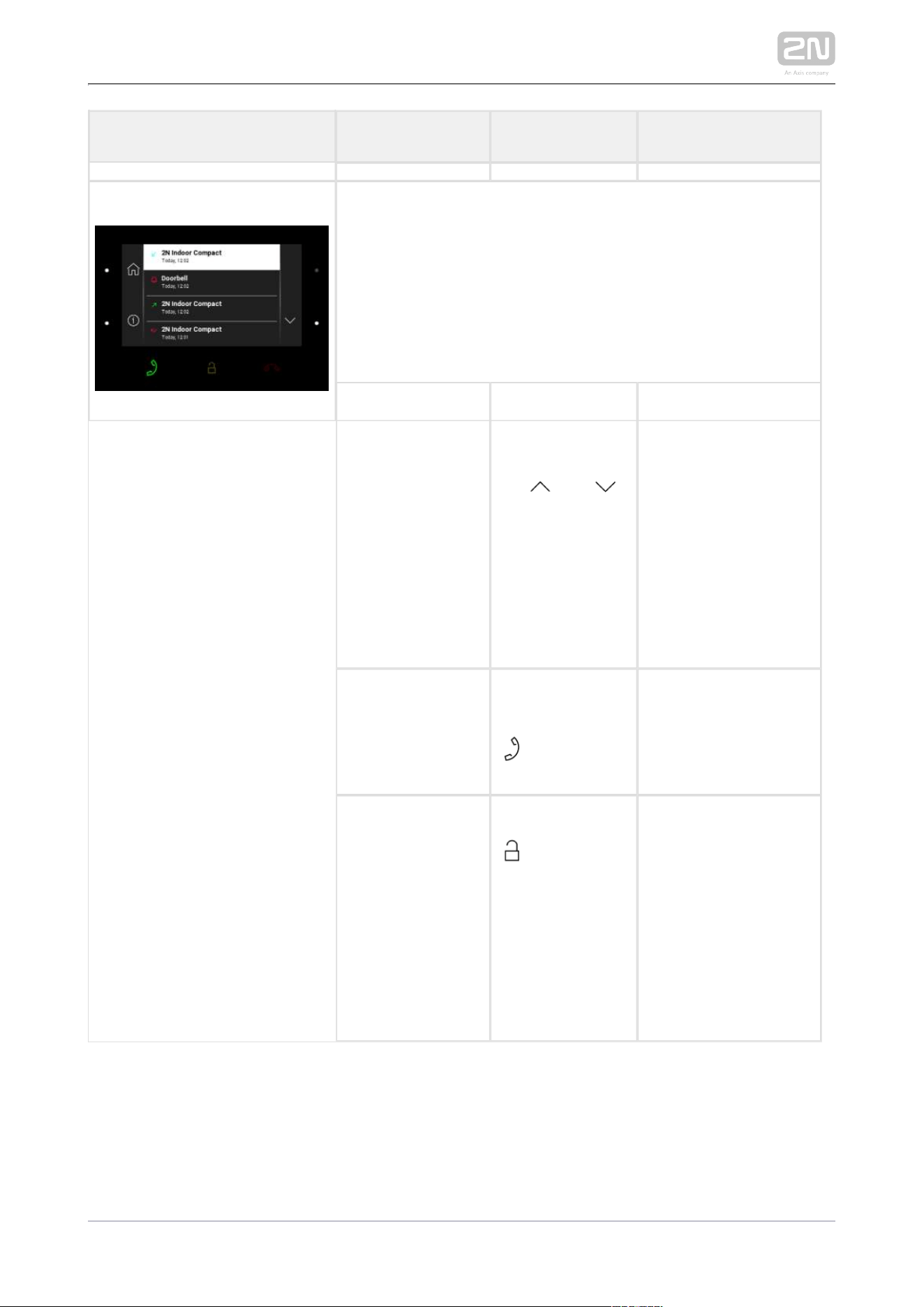
Call Log
The device displays a list of all accomplished calls including
date, time, status (outgoing/incoming/missed) and information
on from/to which destination the call was made. The
destinations that allow for some actions are white-highlighted;
the other ones are gray. The side buttons and call receiving
button are backlit to the maximum, the call end and lock
buttons are ambiently backlit.
Show call detail Press the right-
hand upper
/lower button at
the and
icons to move up
/down the call
log; press the
left-hand lower
button to display
the call detail.
The call detail is
displayed.
Outgoing call Press the call
receiving button
An outgoing call is set
up for the white-
highlighted device on
the list.
Door unlocking
Press lock button
A call is set up or not
depending on the
connection type and
the door is unlocked.
If automatic call end
after unlocking is
enabled, the call is
ended after door
unlocking.
2N TELEKOMUNIKACE a.s., www.2n.cz 109/134
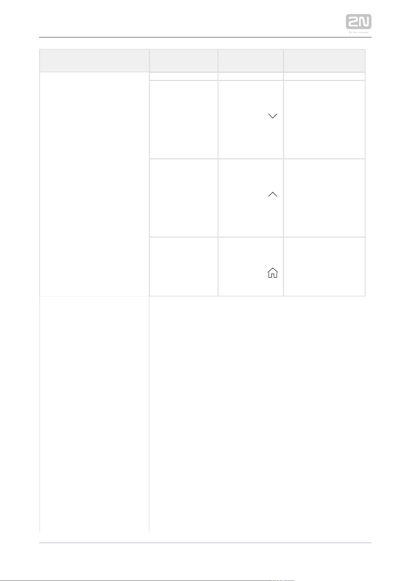
Status and Description User Actions Navigation Actions and Result
Move down the
list
Press the right-
hand lower
button at the
icon
The list goes by one
item down; when the
list end is reached, the
movement stops and
the arrow button goes
off.
Move up the list Press the right-
hand upper
button at the
icon
The list goes by one
item up; when the list
top is reached, the
movement stops and
the arrow button goes
off.
Return to Home
page
Press the left-
hand upper
button at the
icon
Home page is
displayed.
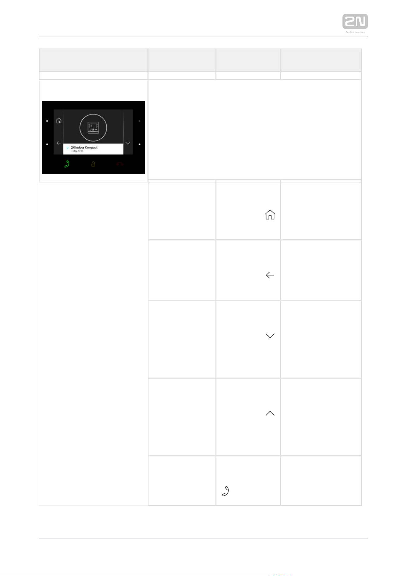
2N TELEKOMUNIKACE a.s., www.2n.cz 110/134
Status and Description User Actions Navigation Actions and Result
Call Log Detail
The display shows a snapshot from the camera set in the 2N IP
intercom if a camera-equipped device initiated the call. A
device symbol is displayed if the call initiating device is not
equipped with a camera. Furthermore, the call day, date and
time, description of the calling/called device and call status
(outgoing/incoming/missed) are displayed. The side buttons
and call receiving button are backlit to the maximum, the other
buttons are ambiently backlit.
Return to Home
page
Press the left-
hand upper
button at the
icon
The device returns to
Home page.
Return to call log Press the left-
hand lower
button at the
icon
The device returns to
the call log.
Move down Press the right-
hand lower
button at the
icon
The list goes by one
item down; when the
list end is reached, the
movement stops and
the arrow button goes
off.
Move up Press the right-
hand upper
button at the
icon
The list goes by one
item up; when the list
top is reached, the
movement stops and
the arrow button goes
off.
Outgoing call
Press the call
receiving button
The device gets in the
In call state.

2N TELEKOMUNIKACE a.s., www.2n.cz 111/134
Status and Description User Actions Navigation Actions and Result
Door unlocking
Press the lock
button
A call is set up or not
depending on the
connection type and
the door is unlocked.
If automatic call end
after unlocking is
enabled, the call is
ended after door
unlocking.
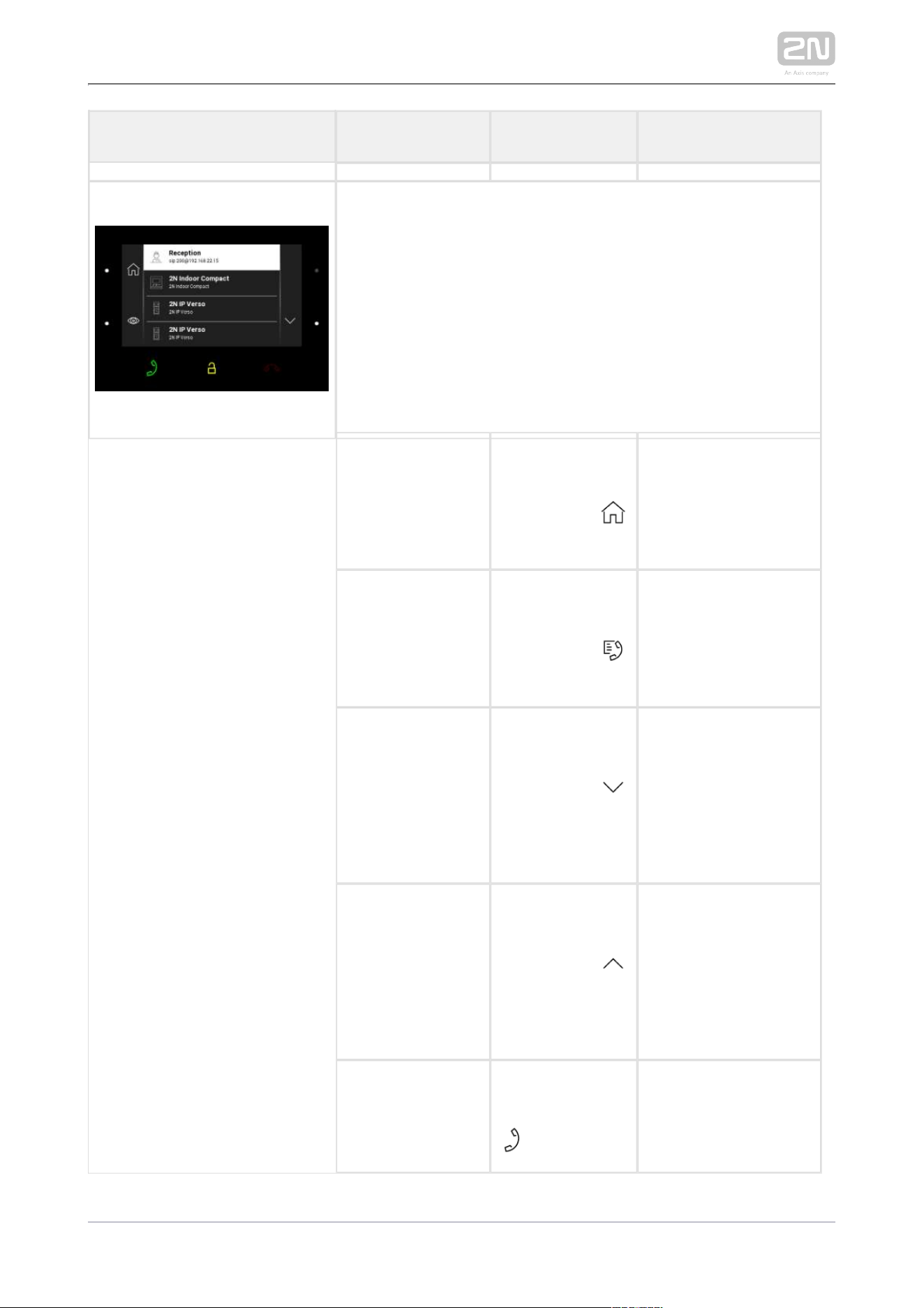
2N TELEKOMUNIKACE a.s., www.2n.cz 112/134
Status and Description User Actions Navigation Actions and Result
Directory
The device displays a list of destinations that can be called. The
destinations include their names and the device type they are
equipped with. The destinations that allow for some actions
(calls) are white-highlighted. The other destinations are gray.
The side buttons and the call receiving button are left-hand
backlit to the maximum. The lock button is backlit to the
maximum in the 2N IP intercoms (LAN or My2N and/or Proxy
devices with DTMF codes) but ambiently backlit in devices
other than those mentioned above.
Return to Home
page
Press the left-
hand upper
button at the
icon
Home page is
displayed.
Return to
directory list
Press the left-
hand upper
button at the
icon
The device returns to
the directory list.
Move down Press the right-
hand lower
button at the
icon
The list goes by one
item down; when the
list end is reached, the
movement stops and
the arrow button goes
off.
Move up Press the right-
hand upper
button at the
icon
The list goes by one
item up; when the list
top is reached, the
movement stops and
the arrow button goes
off.
Outgoing call
Press the call
receiving button
The device gets in the
In call mode.

2N TELEKOMUNIKACE a.s., www.2n.cz 113/134
Status and Description User Actions Navigation Actions and Result
Door unlocking
Press the lock
button
A call is set up or not
depending on the
connection type and
the door is unlocked.
If automatic call end
after unlocking is
enabled, the call is
ended after door
unlocking.

2N TELEKOMUNIKACE a.s., www.2n.cz 114/134
Status and Description User Actions Navigation Actions and Result
Incoming Call
The device is playing the selected ringtone. The display shows
the camera view if available, CLIP and Incoming call message.
The call receiving, lock and call end buttons are backlit to the
maximum. The left-hand lower button at the Mute icon and the
ringing volume up/down buttons to the right are backlit to the
maximum.
Pick up call Press the call
receiving button
The connection is
established and the In
call mode is switched
on.
Reject call Press the call
end button
The incoming call is
discontinued and
Home page is
returned to.
Door unlocking
Press the lock
button
A call is set up or not
depending on the
connection type and
the door is unlocked.
If automatic call end
after unlocking is
enabled, the call is
ended after door
unlocking.
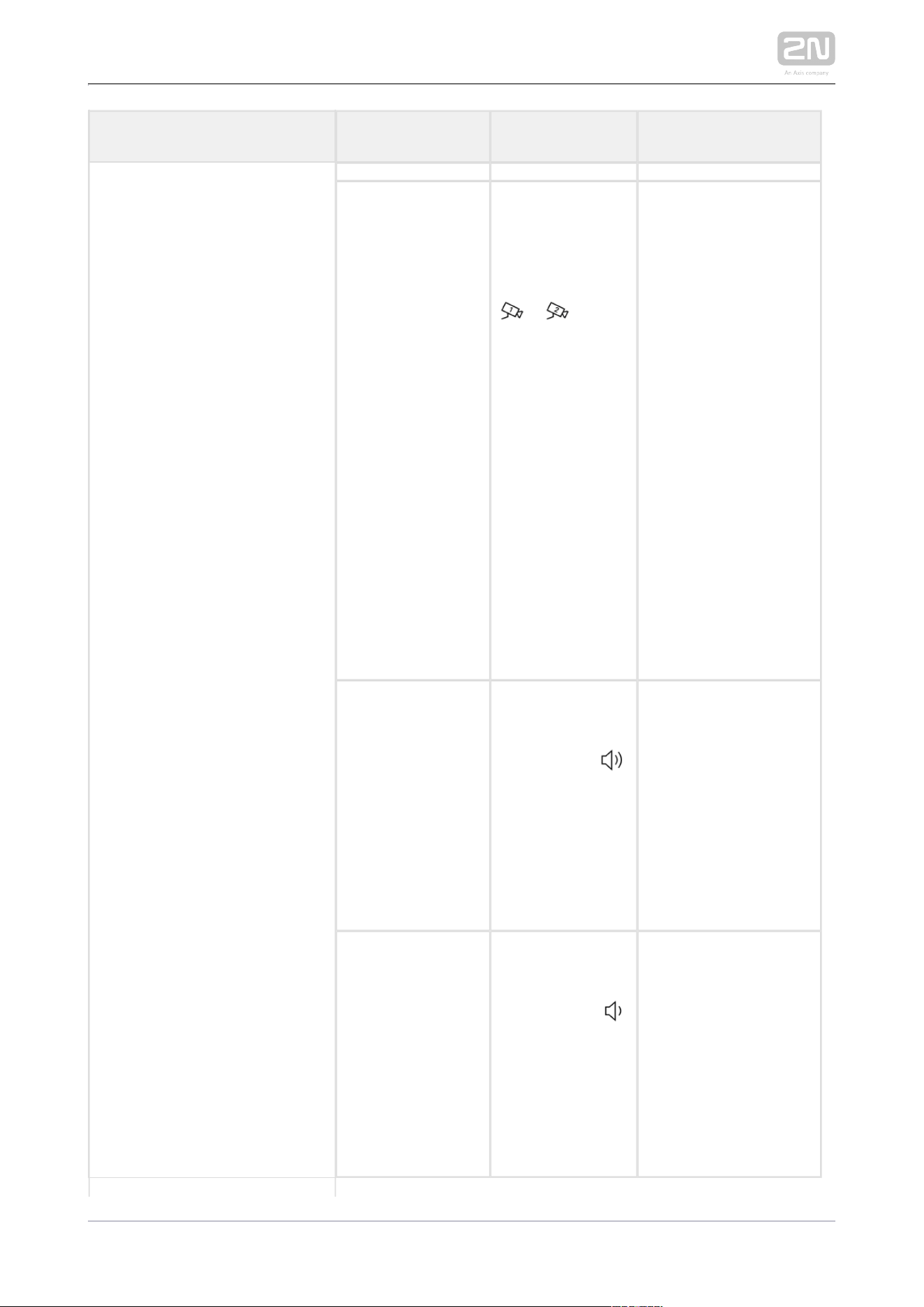
2N TELEKOMUNIKACE a.s., www.2n.cz 115/134
Status and Description User Actions Navigation Actions and Result
The camera is
switched (if
installed and
configured in the
2N IP intercom).
Press the left-
hand upper
button with the
camera icon at
/
The display shows the
view from camera 2,
called device and
Incoming call
message. The call
receiving, lock and
call end buttons are
backlit to the
maximum. The left-
hand lower button at
the Mute icon and the
ringing volume up
/down buttons to the
right are backlit to the
maximum. The
camera 1 switching
button is shining,
camera switch is
performed.
Ringing volume
up
Press the right-
hand upper
button at the
icon
The ringtone volume
is increased by 1 step
by each press. When
the scale top is
reached, the button
goes off. The volume
level is automatically
written to the
settings.
Ringing volume
down
Press the right-
hand lower
button at the
icon
The ringtone volume
is decreased by 1 step
by each press. When
the scale end is
reached, the button
goes off. The volume
level is automatically
written to the
settings.
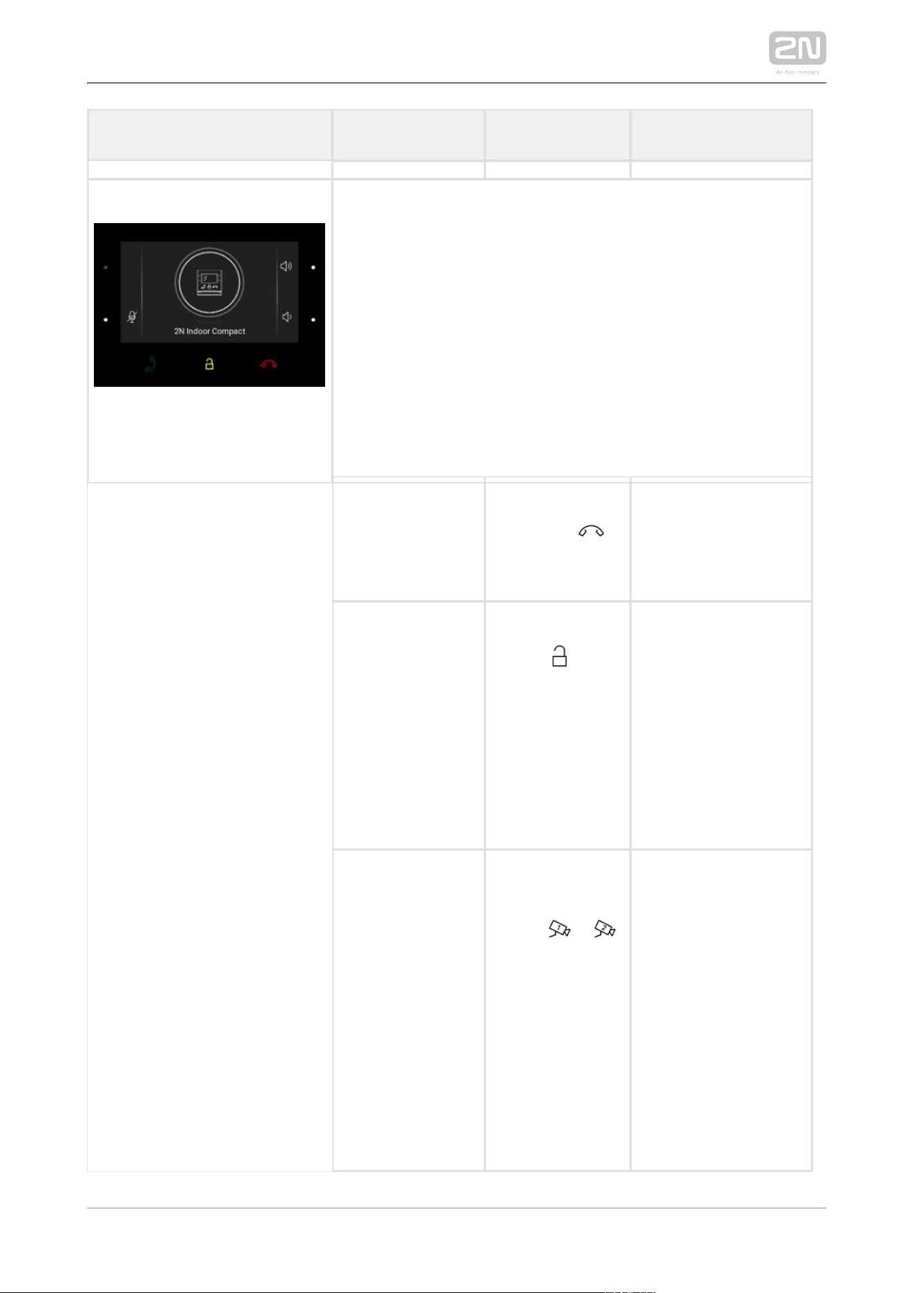
2N TELEKOMUNIKACE a.s., www.2n.cz 116/134
Status and Description User Actions Navigation Actions and Result
Outgoing Call
The device is playing the ringtone. The display shows the
camera view if available, called device ID and Outgoing call
message. The lock and call end buttons are backlit to the
maximum, the call receiving button is ambiently backlit. The
left-hand lower button at the Mute icon is backlit to the
maximum. The ringing volume up/down buttons to the right
are backlit to the maximum. A beep signals that the highest
/lowest level has been achieved, the appropriate button is
ambiently backlit. The camera 2 (if available) switching button
is backlit to the maximum. If camera 2 is unavailable, the
button is ambiently backlit and the icon is not displayed.
End call Press the call
end button
The outgoing call is
discontinued and
Home page is
returned to.
Unlock door Press the lock
button
A call is set up or not
depending on the
connection type and
the door is unlocked.
If automatic call end
after unlocking is
enabled, the call is
ended after door
unlocking.
Switch camera Press the left-
hand upper
button /
The display shows the
view from camera 2,
called device and
Incoming call
message. The call
receiving, lock and
call end buttons are
backlit to the
maximum. The
camera 1 switching
button is lit, camera
switch is performed.

2N TELEKOMUNIKACE a.s., www.2n.cz 117/134
Status and Description User Actions Navigation Actions and Result
Reject call The call is
rejected by the
called device, not
the 2N Indoor
®
user.Compact
The display shows
Call rejected, the call
is terminated and
Home page is
returned to.
Mute call
Press the Mute
button at the
icon
The call is muted.

2N TELEKOMUNIKACE a.s., www.2n.cz 118/134
Status and Description User Actions Navigation Actions and Result
In Call
The display shows the camera view if available, or the called
device ID if no camera is available. A timer is running at the
view. The call receiving button is ambiently backlit. The lock
and call end buttons are backlit to the maximum. The left-hand
lower button at the Mute icon and the ringing volume up/down
buttons are backlit to the maximum. The camera 2 (if available)
switching button is backlit to the maximum. If the second
camera is unavailable, the button is not backlit and the icon is
not displayed.
Mute call Press the Mute
button at the
icon
The device is in the In
call mode but sound is
not transferred to the
calling device. The
Mute icon turns red.
"No one hears you"
message is displayed.
End call Press the call
end button
The outgoing call is
discontinued and
Home page is
returned to.
Unlock door
Press the lock
button
A call is set up or not
depending on the
connection type and
the door is unlocked.
If automatic call end
after unlocking is
enabled, the call is
ended after door
unlocking.
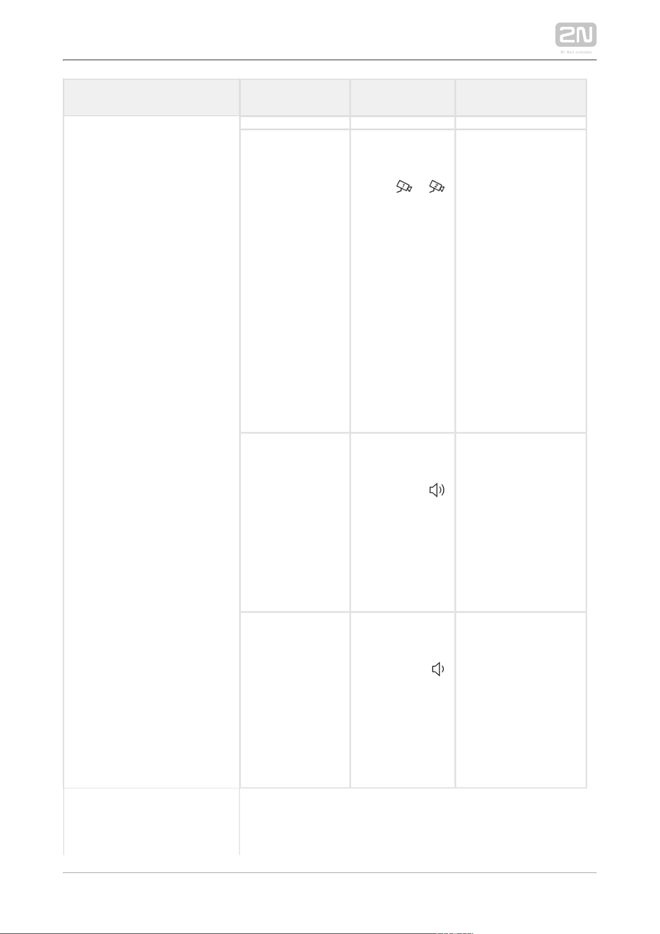
2N TELEKOMUNIKACE a.s., www.2n.cz 119/134
Status and Description User Actions Navigation Actions and Result
Switch camera Press the left-
hand upper
button /
The display shows the
camera 2 view, called
device ID and timer.
The call receiving,
lock and call end
buttons are backlit to
the maximum. The left-
hand lower button at
the Mute icon and the
ringing volume up
/down buttons to the
right are backlit to the
maximum. The
camera 1 switching
button is lit, camera
switch is performed.
Ringing volume
up
Press the right-
hand upper
button at the
icon
The ringtone volume
is increased by 1 step
by each press. When
the scale top is
reached, the button
goes off. The volume
level is automatically
written to the
settings.
Ringing volume
down
Press the right-
hand lower
button at the
icon
The ringtone volume
is decreased by 1 step
by each press. When
the scale end is
reached , the button
goes off. The volume
level is automatically
written to the
settings.

2N TELEKOMUNIKACE a.s., www.2n.cz 120/134
Status and Description User Actions Navigation Actions and Result
Cancel call muting
Press the left-
hand lower
button with the
mute icon
The device is in the In
call mode and sound
is transmitted again to
the calling device. The
mute icon turns white.
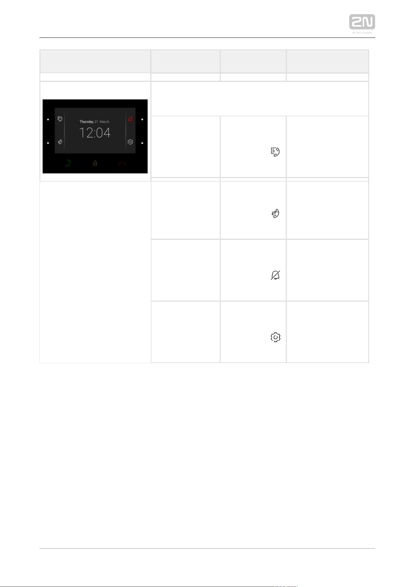
2N TELEKOMUNIKACE a.s., www.2n.cz 121/134
Status and Description User Actions Navigation Actions and Result
DND Mode
The device is at relax, the side buttons are backlit to the
maximum, the other buttons are off. The doorbell icon is red.
Display Directory Press the left-
hand upper
button at the
icon
The list of all available
devices is displayed.
Display Call log Press the left-
hand lower
button at the
icon
The list of all
accomplished calls is
displayed.
Disable DND
mode
Press the right-
hand upper
button at the
icon
DND is deactivated,
the doorbell icon
turns white.
Display Settings
Press the right-
hand lower
button at the
icon
The Settings section is
displayed.
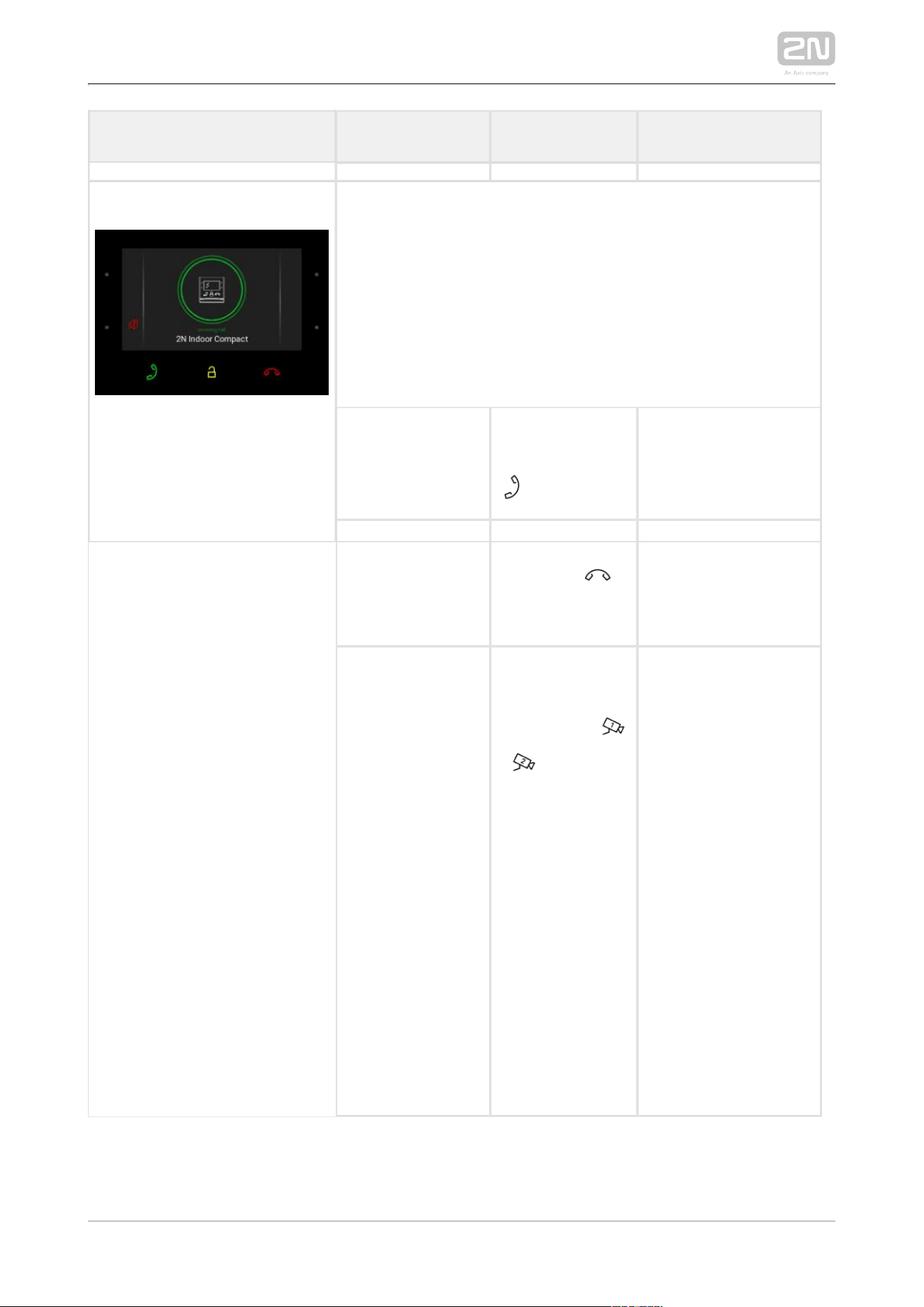
2N TELEKOMUNIKACE a.s., www.2n.cz 122/134
Status and Description User Actions Navigation Actions and Result
Incoming Call in DND Mode
The device does not play the selected ringtone. The display
shows the camera view if available, CLIP and Incoming call
message. The call receiving, lock and call end buttons are
backlit to the maximum. The left-hand lower button at the Mute
icon and the ringing volume up/down buttons to the right are
backlit to the maximum. The camera 2 (if available) switching
button is backlit to the maximum. If camera 2 is unavailable,
the button is not backlit and the icon is not displayed.
Pick up call Press the call
receiving button
The call is connected.
The device is in the In
call mode.
Reject call Press the call
end button
The incoming call is
discontinued and
Home page is
returned to.
Switch camera
Press the left-
hand upper
button at the
/ icon
The display shows the
view from camera 2,
called device ID and
Incoming call
message. The call
receiving, lock and
call end buttons are
backlit to the
maximum. The left-
hand lower button at
the Mute icon and the
ringing volume up
/down buttons to the
right are backlit to the
maximum. The
camera 1 switching
button is lit, camera
switch is performed.
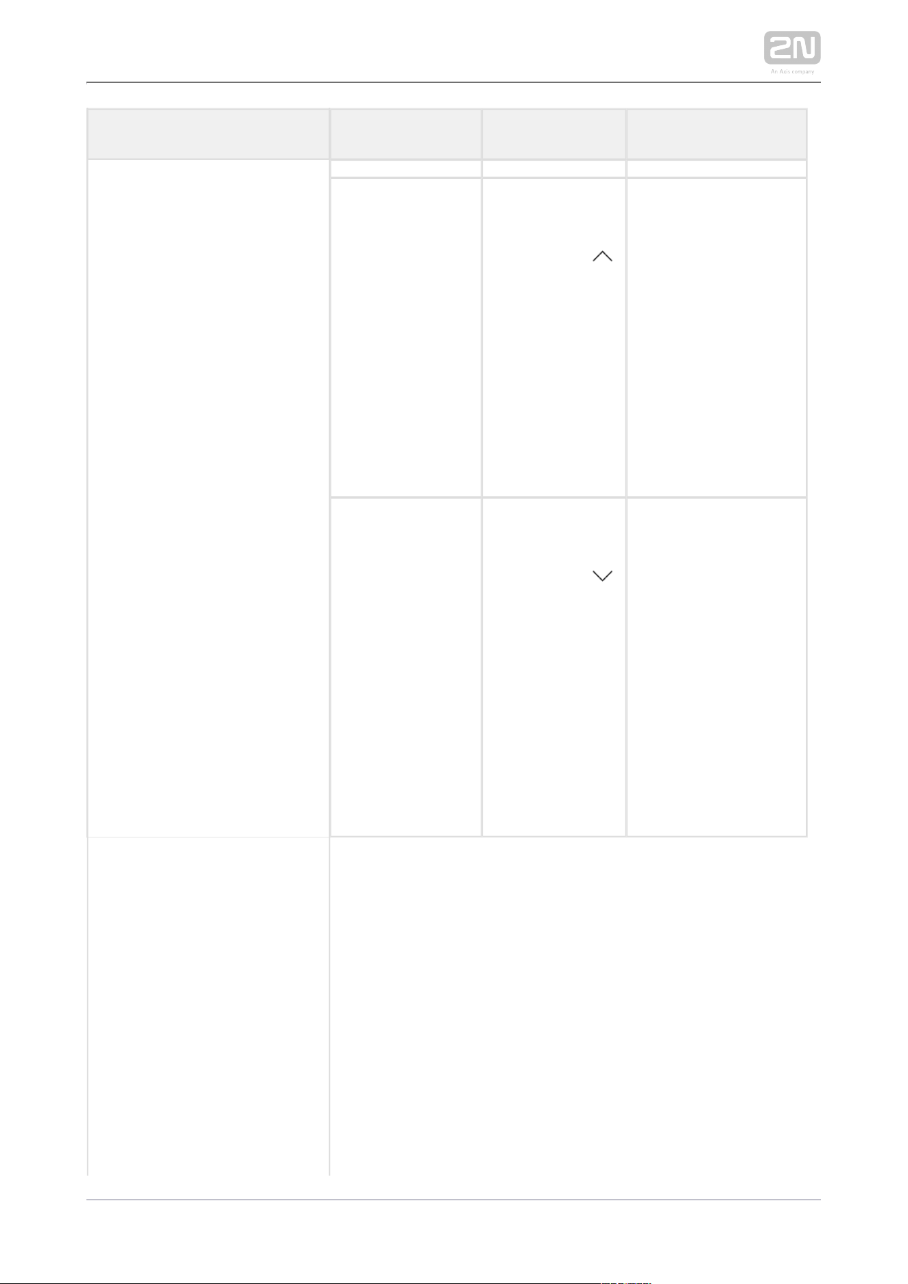
2N TELEKOMUNIKACE a.s., www.2n.cz 123/134
Status and Description User Actions Navigation Actions and Result
Ringing volume
up
Press the right-
hand upper
button at the
icon
The volume starts
increasing from the
lowest possible level.
The ringtone volume
is increased by 1 step
by each press. When
the scale top is
reached, the button
goes off. This action
does not affect the
ringing level when
DND is off.
Ringing volume
down
Press the right-
hand lower
button at the
icon
The volume cannot
start decreasing until
the maximum volume
level is reached. The
ringtone volume is
decreased by 1 step
by each press. When
the scale end is
reached, the button
goes off. This action
does not affect the
ringing level when
DND is off.
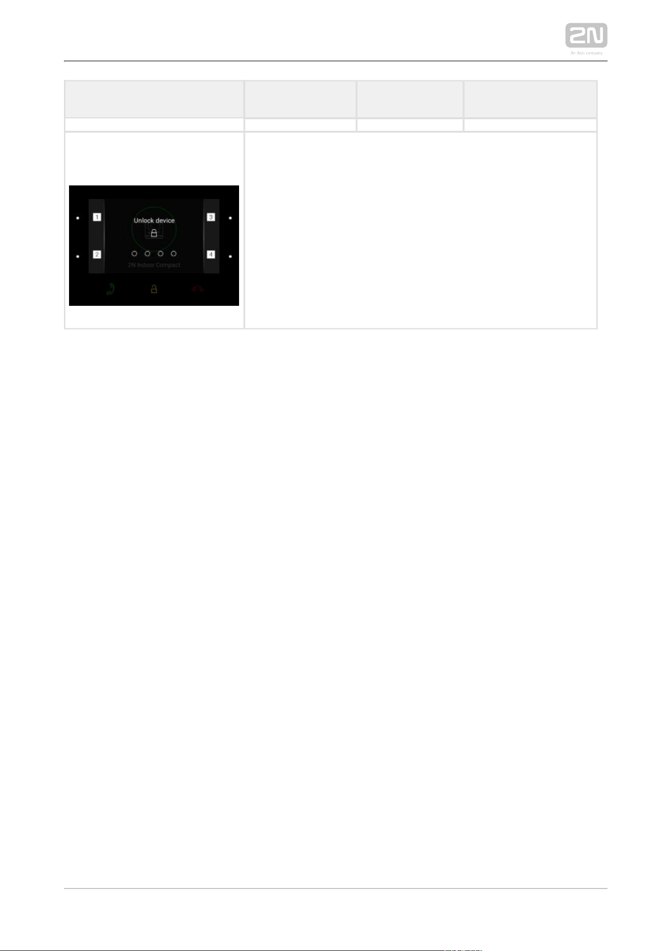
2N TELEKOMUNIKACE a.s., www.2n.cz 124/134
Status and Description User Actions Navigation Actions and Result
Incoming Call with Parental
Lock On
The device is playing the selected ringtone. The display shows
the camera view if available, CLIP and Incoming call message.
The call receiving, lock and call end buttons are backlit to the
maximum. The left-hand lower button at the Mute icon and the
ringing volume up/down buttons to the right are backlit to the
maximum. Press any button to display the parental lock
deactivation command. The call view is displayed on the
background, the call end button is backlit to the maximum, the
incoming call with parental lock on state is recovered (parental
lock deactivation command and dial pad disappear).
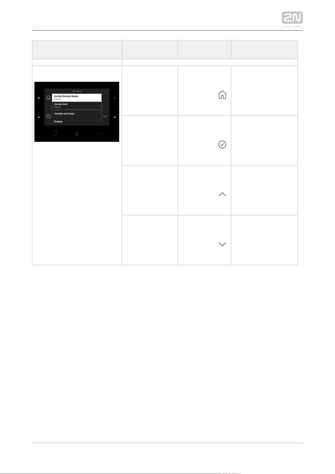
2N TELEKOMUNIKACE a.s., www.2n.cz 125/134
Status and Description User Actions Navigation Actions and Result
Settings Go one level back Press the left-
hand upper
button at the
icon
Confirm selection Press the left-
hand lower
button at the
icon
Move up Press the right-
hand upper
button at the
icon
Move down Press the right-
hand lower
button at the
icon

2N TELEKOMUNIKACE a.s., www.2n.cz 126/134
6. Technical Parameters
Power Supply
Type: 12 V DC +/-10 % adapter or PoE 802.3af
Recommended power supply: 12 V / 1 A
Polarity reversal protection:yes
User Interface
Control: 7 capacitive buttons with white and RGB LED backlight
Display: 4.3´´ with 480 x 272 pixel resolution
Service:RESET button with long press option for factory reset, 3 status LEDs
Signalling protocol
SIP (UDP, TCP, TLS)
Audio
Microphone: integrated
Speaker: 2 W integrated
Induction loop output: 600 mV RMS
Audio stream
Protocols: RTP / RTSP
Codecs: G.711, G.729, G.722, L16/16 kHz
Video stream
Protocols: RTP / RTSP / HTTP, M-JPEG
Codecs: H.264, M-JPEG
Interface
LAN: 10/100BaseT, RJ-45; Cat5e or higher
Doorbell Input

2N TELEKOMUNIKACE a.s., www.2n.cz 127/134
switching contact (button/relay)Input type:
normally open (NO)Contact type:
up to 50 V / 5 mA, DC Contact parameters:
Mechanical Parameters
Dimensions (w x h x d): 152 x 153 x 50 mm
Weight: 387 g
Operating temperature: 0 to 50 °C
Relative humidity: 10 to 90 % non-condensing
Storing temperature: -20 to 70 °C
Recommended altitude: 0 – 2000 m


2N TELEKOMUNIKACE a.s., www.2n.cz 130/134
7.2 Directives, Laws and Regulations -
General Instructions and Cautions
2N Indoor Compact
®
conforms to the following directives and regulations:
2014/35/EU on the harmonisation of the laws of the Member States relating to the
making available on the market of electrical equipment designed for use within certain
voltage limits
2014/30/EU on the harmonisation of the laws of the Member States relating to
electromagnetic compatibility
2011/65/EU on the restriction of the use of certain hazardous substances in electrical
and electronic equipment
2012/19/EU on waste electrical and electronic equipment
Industry Canada
This Class B digital apparatus complies with Canadian ICES-003. / Cet appareil
numérique de la classe B est conforme a la norme NMB-003 du Canada.
FCC
NOTE: This equipment has been tested and found to comply with the limits for a Class
B digital device, pursuant to part 15 of the FCC Rules. These limits are designed to
provide reasonable protection against harmful interference in a residential installation.
This equipment generates, uses and can radiate radio frequency energy and, if not
installed and used in accordance with the instructions, may cause harmful interference
to radio communications. However, there is no guarantee that interference will not
occur in a particular installation. If this equipment does cause harmful interference to
radio or television reception, which can be determined by turning the equipment off
and on, the user is encouraged to try to correct the interference by one or more of the
following measures:
Reorient or relocate the receiving antenna
Increase the separation between the equipment and receiver
Connect the equipment into an outlet on a circuit different from that to which
the receiver is connected
Consult the dealer or an experienced radio/TV technician for help.
Changes or modifications to this unit not expressly approved by the party responsible
for compliance could void the user's authority to operate this equipment.

2N TELEKOMUNIKACE a.s., www.2n.cz 131/134
Caution
In order to ensure the full functioning and guaranteed outputs we strongly
recommend a verification of the timeliness of version of product or facility
already during the installation process. The customer takes into consideration
that the product or facility can achieve the guaranteed outputs and be fully
operational pursuant to the producer’s instructions only by using the most
recent version of product or facility, which has been tested for full
interoperability and has not been determined by the producer as incompatible
with certain versions of other products, only in conformity with the producer’s
instructions, guidelines, manual or recommendation and only in conjunction
with suitable products and facilities of the other producers. The most recent
versions are available on the website https://www.2n.cz/cs_CZ/, or specific
facilities, depending on their technical capacity, allow updating in the
configuration interface. Should the customer use any other version of product
or facility than the most recent one, or the version that has been determined
by the producer as incompatible with certain versions of other producers’
products of facilities, or the product or facility in a way incompatible with the
producer’s instructions, guidelines, manual or recommendation or in
conjunction with unsuitable products or facilities of the other producers, he or
she is aware of all potential limitations of functionality of such a product or
facility and all relating consequences. Should the customer use any other than
the most recent version of the product or facility, or the version that has been
that has been determined by the producer as incompatible with certain
versions of other producers’ products of facilities, or the product or facility in
a way incompatible with the producer’s instructions, guidelines, manual or
recommendation or in conjunction with unsuitable products or facilities of the
other producers, he or she agrees that the company 2N TELEKOMUNIKACE a.
s. is not liable neither for any limitation of such a product’s functionality, nor
for any damage, loss or injury relating to such a potential limitation of
functionality.

2N TELEKOMUNIKACE a.s., www.2n.cz 132/134
Please read this User Manual carefully before using the product. Follow all instructions
and recommendations included herein.
Any use of the product that is in contradiction with the instructions provided herein
may result in malfunction, damage or destruction of the product.
The manufacturer shall not be liable and responsible for any damage incurred as a
result of a use of the product other than that included herein, namely undue
application and disobedience of the recommendations and warnings in contradiction
herewith.
Any use or connection of the product other than those included herein shall be
considered undue and the manufacturer shall not be liable for any consequences
arisen as a result of such misconduct.
Moreover, the manufacturer shall not be liable for any damage or destruction of the
product incurred as a result of misplacement, incompetent installation and/or undue
operation and use of the product in contradiction herewith.
The manufacturer assumes no responsibility for any malfunction, damage or
destruction of the product caused by incompetent replacement of parts or due to the
use of reproduction parts or components.
The manufacturer shall not be liable and responsible for any loss or damage incurred
as a result of a natural disaster or any other unfavourable natural condition.
The manufacturer shall not be held liable for any damage of the product arising during
the shipping thereof.
The manufacturer shall not make any warrant with regard to data loss or damage.
The manufacturer shall not be liable and responsible for any direct or indirect damage
incurred as a result of a use of the product in contradiction herewith or a failure of the
product due to a use in contradiction herewith.
All applicable legal regulations concerning the product installation and use as well as
provisions of technical standards on electric installations have to be obeyed. The
manufacturer shall not be liable and responsible for damage or destruction of the
product or damage incurred by the consumer in case the product is used and handled
contrary to the said regulations and provisions.
The consumer shall, at its own expense, obtain software protection of the product.
The manufacturer shall not be held liable and responsible for any damage incurred as
a result of the use of deficient or substandard security software.
The consumer shall, without delay, change the access password for the product after
installation. The manufacturer shall not be held liable or responsible for any damage
incurred by the consumer in connection with the use of the original password.
The manufacturer also assumes no responsibility for additional costs incurred by the
consumer as a result of making calls using a line with an increased tariff.

2N TELEKOMUNIKACE a.s., www.2n.cz 133/134
Electric Waste and Used Battery Pack Handling
Do not place used electric devices and battery packs into municipal waste containers.
An undue disposal thereof might impair the environment!
Deliver your expired electric appliances and battery packs removed from them to
dedicated dumpsites or containers or give them back to the dealer or manufacturer
for environmental-friendly disposal. The dealer or manufacturer shall take the product
back free of charge and without requiring another purchase. Make sure that the
devices to be disposed of are complete.
Do not throw battery packs into fire. Battery packs may not be taken into parts or
short-circuited either.

2N TELEKOMUNIKACE a.s., www.2n.cz 134/134
2N TELEKOMUNIKACE a.s.
Modřanská 621, 143 01 Prague 4, Czech Republic
Phone: +420 261 301 500, Fax: +420 261 301 599
E-mail: [email protected]
Web: www.2n.cz
v2.29