

AXIST85PoE+NetworkSwitchSeries
TableofContents
Aboutthisdocument........................................3
Solutionoverview...........................................4
Productoverview...........................................5
Getstarted................................................7
Accesstheproductfromabrowser.................................7
Gettoknowyourproduct’swebpage...............................8
Gettoknowyourproduct’sbuilt-inhelp.............................8
Accessdevicesinyourproduct'snetwork........................9
Topologyview..................................................9
Setupexamples.............................................10
SetupaccessVLANs.............................................10
Createredundantlinksbetweenswitchesfornetworkredundancy........10
ReserveanIPaddressbasedonMACaddress.........................11
SetaPoEschedule..............................................11
CheckconnectionstatusviaPoEautochecking.......................12
Maintenance...............................................13
Restarttheproduct..............................................13
Setarebootschedule............................................13
Restoretheproducttofactorydefaultvalues.........................13
Upgradetheproductrmware.....................................13
Reverttoalternatermwareimage.................................14
Specications..............................................15
LEDIndicators..................................................15
2

AXIST85PoE+NetworkSwitchSeries
Aboutthisdocument
Aboutthisdocument
Note
Theproductisintendedforusebynetworkadministratorswhoareresponsibleforoperatingandmaintainingnetwork
equipment.Basicworkingknowledgeofgeneralswitchfunctions,security,theInternetProtocol(IP),andSimpleNetwork
ManagementProtocol(SNMP)isassumed.
ThisUserManualprovidesinformationmainlyonhowto:
•accesstheproduct
•accessconnectedIPdevicesintheproduct’stopologyview
•congureselectedsetupexamples
•performmaintenanceontheproduct
Productfeaturesandtheirsettingsarecoveredinmoredetailintheproduct’scontext-sensitivebuilt-inhelp.Formoreinformation,
seeGettoknowyourproduct’sbuilt-inhelponpage8.
3
AXIST85PoE+NetworkSwitchSeries
Solutionoverview
Solutionoverview
4
AXIST85PoE+NetworkSwitchSeries
Productoverview
Productoverview
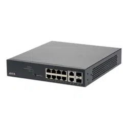
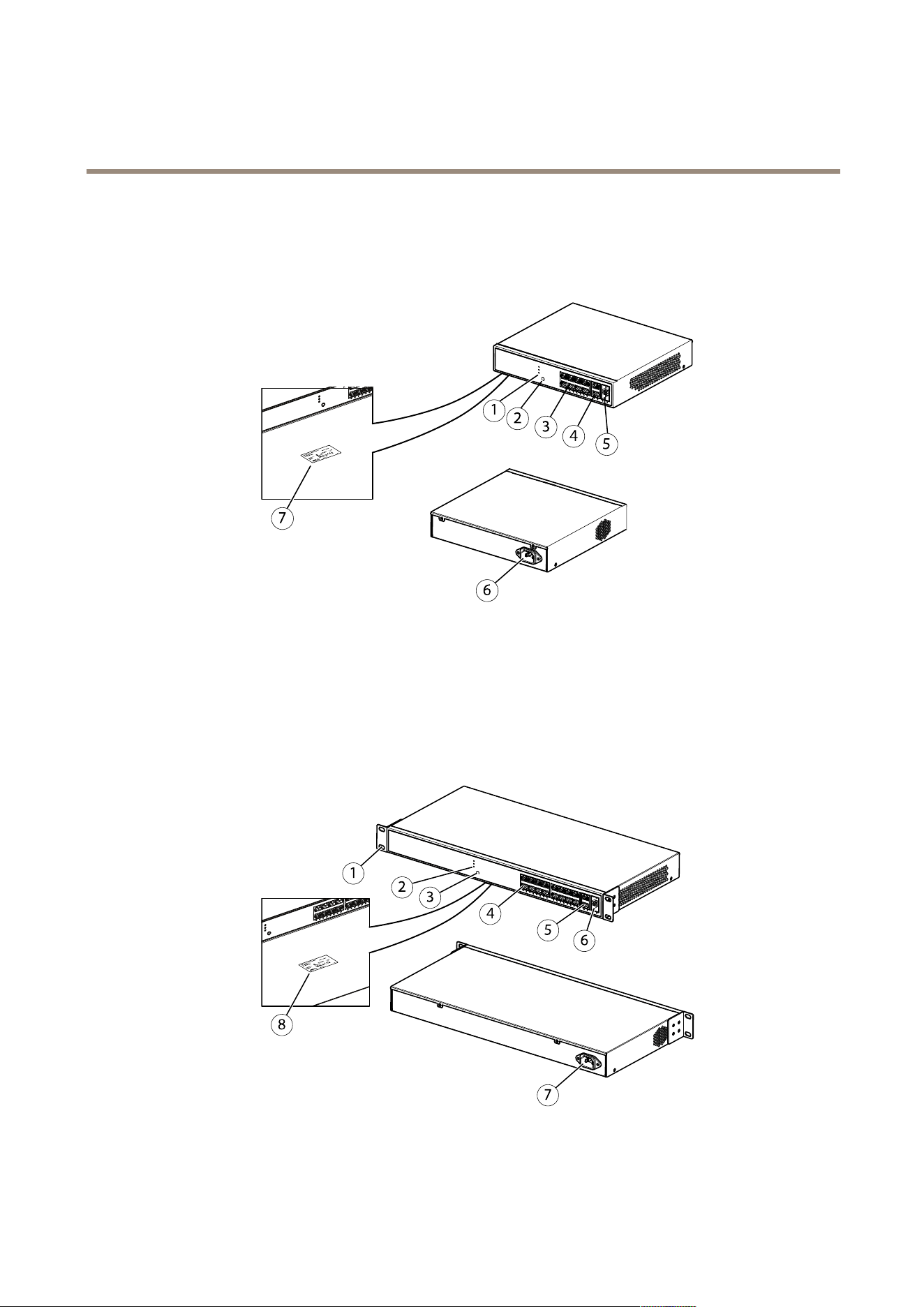
AXIST8508PoE+NetworkSwitch
1
LEDs(frontpanel)
2
Mode/resetbutton
3
RJ45ports(PoE+)x8
4
RJ45ports(non-PoE)x2
5
SFPslotsx2
6
Powerconnector
7
Productlabel
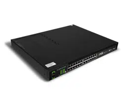
AXIST8516PoE+NetworkSwitch
1
Bracket
2
LEDs(frontpanel)
3
Mode/resetbutton
5
AXIST85PoE+NetworkSwitchSeries
Productoverview
4
RJ45PoEports1-16
5
RJ45port17-18
6
SFPslot17-18
7
Powerconnector
8
Productlabel
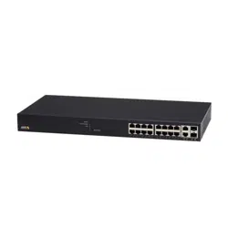
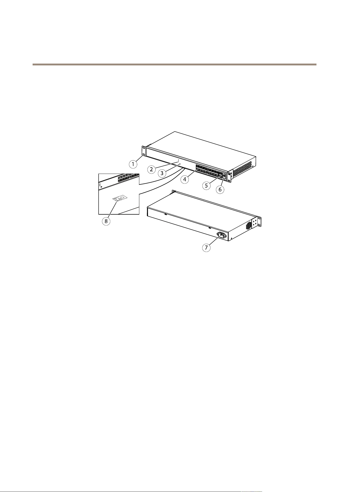
AXIST8524PoE+NetworkSwitch
1
Bracket
2
LEDs(frontpanel)
3
Mode/resetbutton
4
RJ45ports(PoE+)x24
5
RJ45ports(non-PoE)x2
6
SFPslotsx2
7
Powerconnector
8
Productlabel
6

AXIST85PoE+NetworkSwitchSeries
Getstarted
Getstarted
Accesstheproductfromabrowser
Note
Install,connectandpoweruptheproductasspeciedinitsInstallationGuide.
1.UseAXISIPUtilityorAXISCameraManagementtondtheproductonthenetwork.Forinformationonhowtodiscover
andassignanIPaddress,gotowww.axis.com/support
2.Entertheusernameandpasswordprovidedontheproductlabel.
3.Followthestepsinthesetupwizardto:
-Changethepassword(recommendedforsecurityreasons)
-SettheIPaddressviaDHCPormanually
-ConguretheDHCPserver
-Setthedate&timeinformation
-Setthesysteminformation
4.ClickApply.
5.Reloginusingthenewpassword.
Youwillnowentertheproduct’swebpage,andwillbeabletocongureandmanagetheproduct.
7
AXIST85PoE+NetworkSwitchSeries
Getstarted
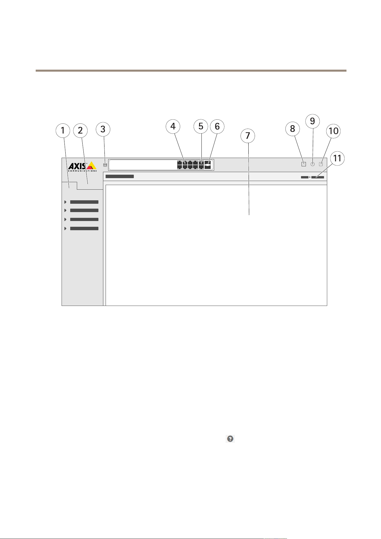
Gettoknowyourproduct’swebpage
1
Basicfeatures
2
Advancedfeatures
3
Togglebutton-switchbetweenwindowedandfullscreens
4
RJ45port(PoE+)statusindicators
5
RJ45port(non-PoE)statusindicators
6
SFPportstatusindicators
7
Contentareaforbasic/advancedfeatures
8
Savebutton-savethestart-upconguration
9
Helpbutton-accessthecontext-sensitivebuilt-inhelp
10
Logoutbutton
11
Menupath
Gettoknowyourproduct’sbuilt-inhelp
Yourproducthasacontext-sensitivebuilt-inhelp.Thehelpprovidesmoredetailedinformationontheproduct’sbasicandadvanced
featuresandtheirsettings.Toaccessthehelpcontentforanygivenview,click
.Somehelpcontentalsoincludesclickableterms
andacronymsthatareexplainedinmoredetailinthebuilt-inglossary.
8
AXIST85PoE+NetworkSwitchSeries
Accessdevicesinyourproduct'snetwork
Accessdevicesinyourproduct'snetwork
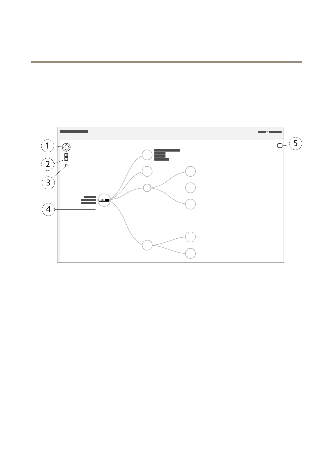
Topologyview
Thetopologyviewallowsyoutoremotelyaccess,manageandmonitoralldiscoveredIPdevicesinyourproduct’snetwork,for
exampleviaatabletorasmartphone.TodisplaythediscoveredIPdevicesinagraphicalnetwork,gotoBasic>TopologyView.
1
Arrowbuttontomovetheviewinfourdirections
2
Zoominandzoomoutbuttons
3
Drop-downbuttontoaccessandchangedeviceinformationtobedisplayedintheview
4
Contentareafordevicesdiscoveredinthenetwork
5
Settingsbuttontoaccessandchangedevice,groupandcongurationinformation
Whenyouclickadeviceiconinthetopologyview,adeviceconsoleisopenedtoallowyouaccessto:
•dashboardconsolewithdeviceinformationandavailabledevice-specicactions,suchaslogin,diagnostics,ndswitch,
PoEcongurationandreboot
•noticationconsolewithinformationonalarmsandlogstriggeredbyevents
•monitorconsolewithinformationondevicetrafc
9
AXIST85PoE+NetworkSwitchSeries
Setupexamples
Setupexamples
SetupaccessVLANs
VLANSaretypicallyusedonlargenetworkstocreatemultiplebroadcastdomains,buttheycanalsobeusedtosegregatenetwork
trafc.Forexample,videotrafccanbepartofoneVLAN,andothernetworktrafccanbepartofanother.
1.GotoAdvanced>VLANs>Conguration.
2.UnderGlobalVLANConguration,entertheVLANsyouwanttocreatetotheAllowedAccessVLANseld.Forexample,if
youenter,1,10-13,200,300,thefollowingVLANIDswillbecreated:1,10,1 1,12,13,200and300.
3.ToassignacreatedVLANIDtoagivenportunderPortVLANConguration,entertheIDtothePortVLANeld.
4.ClickApply.
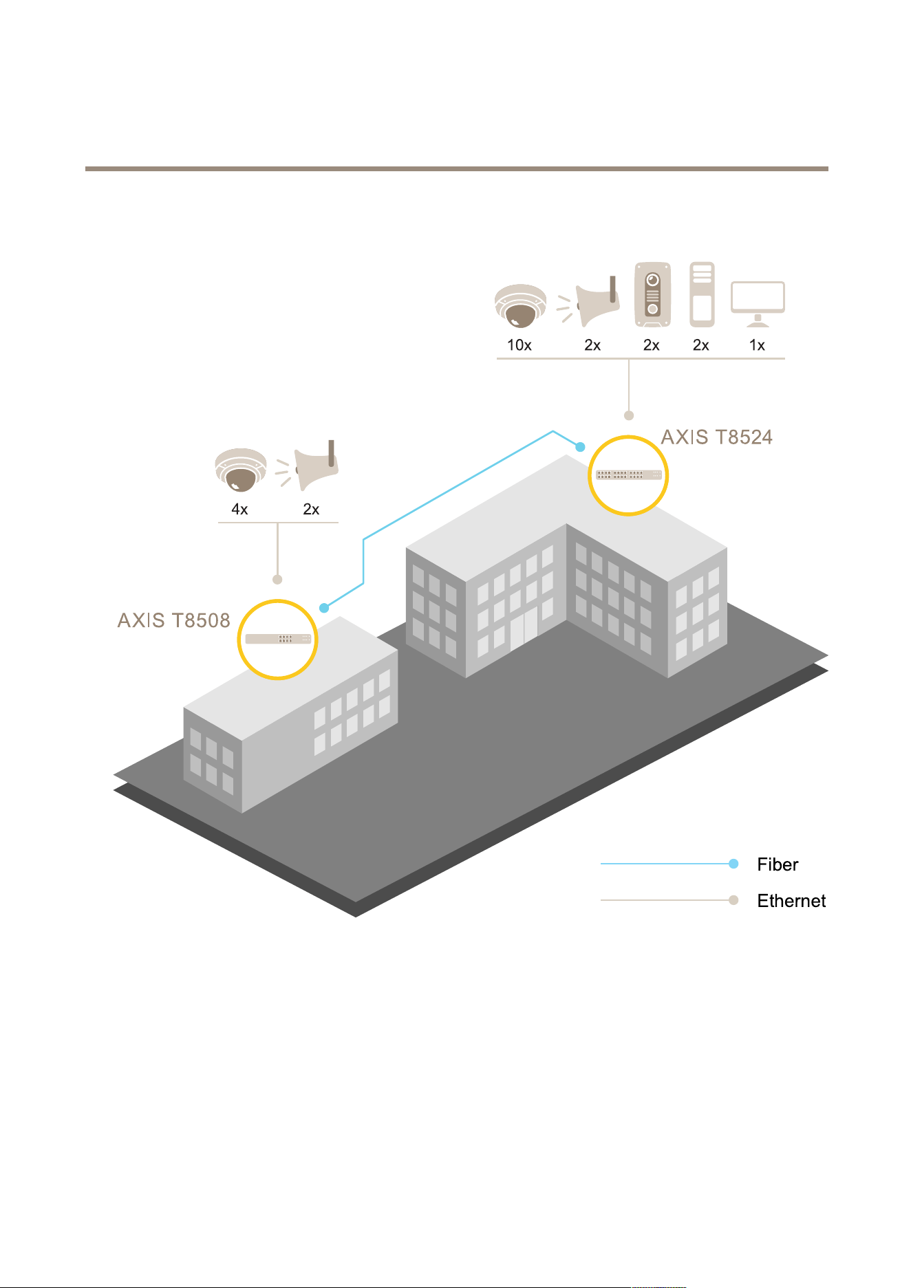
Createredundantlinksbetweenswitchesfornetworkredundancy
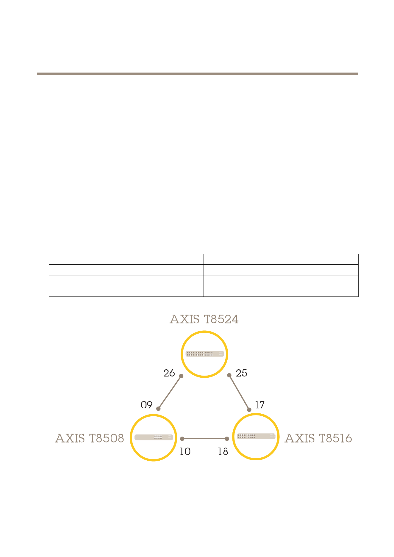
Ifnetworkredundancyisrequired,youcancreateredundantlinksbetweenswitchesusingspanningtreeconguration.
Inthisexample,thereare3switchesconnectedbyaredundantlinkandnoextraVLANS.Ifanyoftheuplinksbetweentheswitches
shouldfail,theredundantlinkisactivatedandprovidesnetworkconnectivity.
DeviceNameModelName
Switch-01AXIST8524
Switch-02AXIST8516
Switch-03AXIST8508
Tocreatearedundantlinkoneachswitch’swebpage:
1.GotoAdvanced>SpanningTree>Conguration>BridgeSettings.
10

AXIST85PoE+NetworkSwitchSeries
Setupexamples
2.UnderBasicSettingsintheProtocolVersiondrop-downmenu,selectRSTP,andclickApply.
3.GotoAdvanced>SpanningTree>Conguration>CISTPort.
4.UnderCISTNormalPortConguration,makesurethatSTPEnabledisselectedfortheswitch’sportsasfollows:
-Switch–01:ports25and26
-Switch–02:ports17and18
-Switch–03:ports9and10
5.ClickApply.
Note
Ifyouwanttomakesurethatacertainportisusedasaprimarycommunicationlink,enterPathCostforthatportunder
CISTNormalPortConguration.Ifnotspecied,theswitchchoosestheportautomatically.Forexample,ifyouwanttouse
port17astheprimarycommunicationlink,enterPathCostvalue10toport25andPathCostvalue50toport18.
Tosavethestart-upconguration,click
ontheproduct’swebpage.SeeGettoknowyourproduct’swebpageonpage8.
ReserveanIPaddressbasedonMACaddress
1.GotoAdvanced>DHCPServer>Conguration>Pool.
2.ClickAddNewPool.
3.Enteranameforthepool,forexample00:01:02:03:04:05,andclickApply.Nospacesareallowedinthename.
4.Toaccessthepoolsettings,clicktheaddedname.
5.IntheTypedrop-downmenu,selectHost.
6.Enterotherrequiredsettings,suchasIPaddress,SubnetMaskandDefaultRouter.
7.IntheClientIdentierdrop-downmenu,selectMAC.
8.IntheHardwareAddresseld,enterF8-16-54-B2-35-63.
9.ClickApply.
Tosavethestart-upconguration,clickontheproduct’swebpage.SeeGettoknowyourproduct’swebpageonpage8.
SetaPoEschedule
IfyouhaveacertaintimeframewhereyouwanttheswitchtoprovidePoE,forexample,toyourcameras,itcanbeusefultocreatea
PoEscheduleandassignittooneormorePoEports.Youcancreateupto16PoEscheduleproles.
TocreateaPoEschedule:
1.GotoAdvanced>PoE>Conguration>ScheduleProle.
2.IntheProledrop-downmenu,selectanumberfortheprole.
3.Changethedefaultprolenameasneeded.
4.TospecifywhenyouwantPoEtoswitchon,selecthours(HH)andminutes(MM)intheStartTimedrop-downmenu.
5.TospecifywhenyouwantPoEtoswitchoff,selecthours(HH)andminutes(MM)intheEndTimedrop-downmenu.
11

AXIST85PoE+NetworkSwitchSeries
Setupexamples
-Ifyouwanttousethesamescheduleforalldaysoftheweek,selectthestartandendtimesontheWeekDay
rowmarkedwithanasterisk(*).
-Ifyouwanttousethesamescheduleforcertaindaysoftheweekonly,selectthestartandendtimesfor
selecteddaysontherespectiveWeekDayrows.
6.ClickApply.
ToassignthecreatedPoEscheduletooneormorePoEports:
1.GotoAdvanced>PoE>Conguration>PowerManagement.
2.UnderPoEPortCongurationinthePoEScheduledrop-downmenu,selectthenumberofthespeciedPoEschedule
prole.
-Ifyouwanttoassignthesameproleforallports,selecttheprolenumberonthePortrowmarkedwithan
asterisk(*).
-Ifyouwanttoassignthesameproleforcertainportsonly,selecttheprolenumbersforselectedportsonthe
respectivePortnumberrows.
3.ClickApply.
CheckconnectionstatusviaPoEautochecking
YoucanusePoEautocheckingifyouwanttoperiodicallychecktheconnectionstatusbetweenyourswitchandthePoEenabled
networkdeviceconnectedtoit.If,duringautochecking,thenetworkdevicedoesnotrespondtotheswitch,theswitchwill
automaticallyrestartthePoEportthenetworkdeviceisconnectedto.
Toenableautocheckingviathetopologyview:
1.GotoBasic>TopologyView.
2.ToopentheDashboardconsoleofyourswitch,clicktheswitchicon.
3.ClickPoECong.
4.InthePoEAutoCheckingdrop-downmenu,selectEnable.
Toconguretheautocheckingparameters:
1.GotoAdvanced>PoE>Conguration>AutoChecking.
2.InthePingIPAddresseld,entertheIPaddressofthedevicethatisconnectedtotheportyouwanttoassignauto
checkingfor.
3.Entertheotherneededparameters,forexample:
-Port:1
-PingIPAddress:192.168.0.90
-StartupTime:60
-IntervalTime(sec):30
-RetryTime:3
-FailureAction:RebootRemotePD
-Reboottime(sec):15
4.ClickApply.
12

AXIST85PoE+NetworkSwitchSeries
Maintenance
Maintenance
Restarttheproduct
Note
Anycongurationlesorscriptsyouhavesavedintheproductareavailableafterrestart.
1.GotoAdvanced>Maintenance>RestartDevice.
2.Ifyouwanttosimulateapower-on(coldrestart),selectForceCoolRestart.Thiswillimpactthetrafcroutedthrough
theproduct.
3.ClickYes.
Afterrestart,theproductwillbootnormally.
Setarebootschedule
Note
Anycongurationlesorscriptsyouhavesavedintheproductareavailableafterreboot.
1.GotoAdvanced>Maintenance>RebootSchedule.
2.SetModetoEnabled.
3.Selecttheweekdayandtimeforreboot.
4.ClickApply.
Restoretheproducttofactorydefaultvalues
Important
Anycongurationlesorscriptsyouhavesavedintheproductarerestoredtofactorydefaultvalues.
1.GotoAdvanced>Maintenance>FactoryDefaults.
2.IfyouwanttokeepthecurrentIPsettings,selectKeepIPsetup.
3.ClickYes.
Note
Formoreinformationonhowtorestoretheproducttofactorydefaultvaluesusingthemode/resetbutton,seetheproduct’s
InstallationGuide.
Upgradetheproductrmware
Important
Webaccessisnotavailableduringrmwareupgrade.Thermwareupgradetakesaboutoneminute,andthesystemLED
blinksgreenduringtheupgradeprocess.Donotrestartorpoweroffthedeviceduringthistime.
1.GotoAdvanced>Maintenance>Firmware>FirmwareUpgrade.
2.Toselectthermwarelefromaspeciedlocation,clickBrowse.
3.Ifyouwanttosimulateapower-on(coldrestart)afterrmwareupgrade,selectForceCoolRestart.Thiswillimpactthe
trafcroutedthroughtheproduct.
13

AXIST85PoE+NetworkSwitchSeries
Maintenance
4.ClickUpload.
Afterrmwareupgrade,theproductwillrestartnormally.
Reverttoalternatermwareimage
Youcanchoosetousethealternate(backup)rmwareimageinsteadoftheactive(primary)rmwareimageintheproduct.
InformationtablesonbothimagesareshownunderAdvanced>Maintenance>Firmware>FirmwareSelection.
Note
•Iftheactiveimageisalreadysetasthealternateimage,onlytheActiveImagetableisshown,andtheActivateAlternate
Imagebuttonisdisabled.
•Ifthealternateimageisalreadysetastheactiveimage(eithermanuallyorduetocorruptedprimaryimage),andanew
rmwareimageisuploadedtotheproduct,thenewimagewillautomaticallybesetastheactiveimage.
•Firmwareversionanddateinformationmaybeemptyforolderrmwarereleases.Thisisnormal.
Tosetthealternateimageastheactiveimage:
1.GotoAdvanced>Maintenance>Firmware>FirmwareSelection.
2.ClickActivateAlternateImage.
14

AXIST85PoE+NetworkSwitchSeries
Specifications
Specifications
Tondthelatestversionoftheproduct’sdatasheet,gototheproductpageonaxis.comandlocateSupport&Documentation.
LEDIndicators
SystemLED
LED
Color
Indication
Green(lit)
TheswitchispoweredON.
N/A
Theswitchisnotreceivingpower.
System
Red(lit)
Anabnormalstate,suchasexceeding
operatingtemperaturerange,hasbeen
detectedintheswitch.
ModeLED
LED
Color
Indication
Green(lit)
TheRJ45/SFPPortStatusLEDsare
displayinglinkstatusandnetwork
activityofeachport,withconnection
speedof1000Mbps.
Link/Act/Speed
Amber(lit)
TheRJ45/SFPPortStatusLEDsare
displayinglinkstatusandnetwork
activityofeachport,withconnection
speedof10/100Mbps.
PoE
Green(lit)
TheRJ45PortStatusLEDsaredisplaying
PoEpoweringstatusofeachport.
BypressingtheMode/Resetbuttoninlessthan2secondstochangeLEDmodes(Link/Act/SpeedModeorPoEMode),userscancheck
theportstatusbyreadingtheLEDbehaviorsinthetablesbelow.
Link/Act/SpeedModeLED
LED
Color
Indication
Green(lit)
Theportisenabledandestablishedalink
toconnecteddevice,andtheconnection
speedis1000Mbps.
Green(blink)
Theportistransmitting/receivingpackets,
andtheconnectionspeedis1000Mbps.
Amber(lit)
Theportisenabledandestablishedalink
toconnecteddevice,andtheconnection
speedis10/100Mbps.
Amber(blink)
Theportistransmitting/receivingpackets,
andtheconnectionspeedis10/100Mbps.
RJ45ports
N/A
Theporthasnoactivenetworkcable
connected,oritisnotestablishedalink
toconnecteddevice.Otherwise,theport
mayhavebeendisabledthroughthe
productuserinterface.
15

AXIST85PoE+NetworkSwitchSeries
Specifications
Green(lit)
Theportisenabledandestablishedalink
toconnecteddevice,andtheconnection
speedis1000Mbps.
Green(blink)
Theportistransmitting/receivingpackets,
andtheconnectionspeedis1000Mbps.
Amber(lit)
Theportisenabledandestablishedalink
toconnecteddevice,andtheconnection
speedis100Mbps.
Amber(blink)
Theportistransmitting/receivingpackets,
andtheconnectionspeedis100Mbps.
SFPports
N/A
Theporthasnoactivenetworkcable
connected,oritisnotestablishedalink
toconnecteddevice.Otherwise,theport
mayhavebeendisabledthroughthe
productuserinterface.
PoEModeLED
LED
Color
Indication
Green(lit)
Theportisenabledandsupplyingpower
toconnecteddevice.
Amber(lit)
Anabnormalstate,suchasoverload
status,hasbeendetectedintheproduct.
RJ45ports
N/A
Theporthasnoactivenetworkcable
connected,oritisnotconnectedaPoE
PDdevice.Otherwise,theportmayhave
beendisabledthroughtheproductuser
interface.
16

UserManualVer.M1.17
AXIST85PoE+NetworkSwitchSeriesDate:October2017
©AxisCommunicationsAB,2017
PartNo.1743995