
SDG2000X Service Manual I
Service Manual
SDG2000X Series
Function/Arbitrary Waveform Generator
2016 SIGLENT TECHNOLOGIES CO., LTD

Guaranty and Declaration
Copyright
SIGLENT TECHNOLOGIES CO., LTD. All Rights Reserved.
Trademark Information
SIGLENT is the registered trademark of SIGLENT TECHNOLOGIES CO., LTD
Declaration
SIGLENT products are protected by patent law in and outside of P.R.C.
SIGLENT reserves the right to modify or change parts of or all the
specifications or pricing policies at company‟s sole decision.
Information in this publication replaces all previously corresponding
material.
Any form of copying, extracting or translating the contents of this manual is
not allowed without the permission of SIGLENT.
SIGLENT will not be responsible for losses caused by either incidental or
consequential in connection with the furnishing, use or performance of this
manual as well as any information contained.
Product Certification
SIGLENT guarantees this product conforms to the national and industrial
standards in China as well as the ISO9001: 2008 standard and the ISO14001:
2004 standard. Other international standard conformance certification is in
progress.

SDG2000X Service Manual.doc
III
General Safety Summary
Carefully read the following safety precautions to avoid any personal injuries or damages
to the instrument and any product connected to it. To avoid potential hazards, please use
the instrument as specified.
Only qualified technical personnel should service this instrument.
Avoid fire or open flame.
Use properly rated power line connections.
Use only the specified power line which has been approved by your local regulatory
agency.
Ground the Instrument.
The instrument is grounded through the protective ground conductor of the power line. To
avoid electric shock, the ground conductor must be connected to the earth ground. Make
sure the instrument is grounded correctly before connecting its input or output terminals.
Connect the signal wire correctly.
The potential of the signal wire ground is equal to the earth, therefore do not connect the
signal wire to a high voltage. Do not touch the exposed contacts or components.
Observe all terminal ratings.
To avoid fire or electric shock, please observe all ratings and label instructions on the
instrument. Before connecting the instrument, please read the manual carefully to gain
more information about the ratings.
Do not operate with suspected failures.
If you suspect that the product is damaged, please allow only qualified service personnel
to troubleshoot and repair it.
Avoid circuit or wire exposure.
Do not touch exposed contacts or components when the power is on.
Do not operate in wet/damp conditions.
Do not operate in an explosive atmosphere.
Keep the surface of the instrument clean and dry.
Safety Terms and Symbols
Terms used on the instrument. Terms may appear on the instrument:
DANGER: Indicates an injury or hazard that may immediately happen.
WARNING: Indicates an injury or hazard that may not immediately happen.
CAUTION: Indicates that a potential damage to the instrument or other property might
occur.
Symbols used on the instrument. Symbols may appear on the instrument:
Hazardous Protective Warning Chassis Power
Voltage Earth Ground Ground Switch

Catalog
Guaranty and Declaration .................................................................................................... II
General Safety Summary ................................................................................................... III
Overview of this Document ................................................................................................ VI
The SDG2000X Series Generator at a Glance ............................................................... VIII
The Front Panel at a Glance.............................................................................................. IX
The Rear Panel at a Glance ............................................................................................. XII
Chapter 1 Specifications .................................................................................................... 13
Chapter 2 Quick Start ........................................................................................................ 21
To Prepare the Generator for Use .............................................................................. 22
To Adjust the Carrying Handle .................................................................................... 23
To Set the Output Frequency ..................................................................................... 24
To Set the Output Amplitude ....................................................................................... 26
To Set the DC offset ................................................................................................... 28
To Set the Duty Cycle of a Square Waveform ............................................................ 30
To Set the Symmetry of a Ramp Waveform ............................................................... 32
To Generate a Pulse Waveform ................................................................................. 34
To Generate a Noise Waveform ................................................................................. 37
To Set the DC Voltage ................................................................................................ 39
To Output a Built-In Arbitrary Waveform ..................................................................... 41
To Use the Built-In Help System ................................................................................. 43
Chapter 3 Calibration ......................................................................................................... 44
Calibration Interval ...................................................................................................... 44
Adjustment is Recommended .................................................................................... 44
Automating Calibration Procedures ........................................................................... 44
Recommended Test Equipment ................................................................................. 44
Test Considerations .................................................................................................... 45
Performance Verification Test ..................................................................................... 45
DC Output Verification ......................................................................................... 46
AC Amplitude Verification .................................................................................... 47
Frequency Response Verification ....................................................................... 48
General Adjustment Procedure .................................................................................. 50
Software Environment ......................................................................................... 51
Warming up ......................................................................................................... 51
Channel Adjustment ............................................................................................ 52
Frequency Response Adjustment ....................................................................... 57
TimeBase Calibration .......................................................................................... 58
Chapter 4 Assembly Procedures ....................................................................................... 59
Security Consideration ............................................................................................... 59
List of Modules ........................................................................................................... 60
Required Tools ............................................................................................................ 60
Disassembly Procedures ............................................................................................ 61

SDG2000X Service Manual.doc
V
Chapter 5 Troubleshooting ................................................................................................ 66
ESD Precautions ........................................................................................................ 66
Required Equipments ................................................................................................. 66
Channel Board Drawing ............................................................................................. 67
Main Board Drawing ................................................................................................... 68
Check the Power Supply ............................................................................................ 69
Check the Channel Board .......................................................................................... 71
Voltage Checking ................................................................................................ 71
10 MHz Clock Source Checking ......................................................................... 72
FPGA Checking ................................................................................................... 72
Connector Checking ............................................................................................ 72
Check the Main Board ................................................................................................ 73
Voltage Checking ................................................................................................ 73
Main Board Clock Checking ................................................................................ 73
ARM CPU System Checking ............................................................................... 74
Connector Checking ............................................................................................ 74
Quick Guide for General Failures ............................................................................... 75
Chapter 6 Maintenance ..................................................................................................... 76
Maintain Summary ...................................................................................................... 76
Repackaging for Shipment ......................................................................................... 76
Contact SIGLENT ....................................................................................................... 77

Overview of this Document
This document is for the SDG2000X series arbitrary waveform generator,
which will be mostly referred to “the generator” for short in the following text.
The main contents described in this manual are:
The SDG2000X Series Generator at a Glance
This part introduces the main technology characteristics for the SDG2000X
generator.
The Front Panel at a Glance
This section introduces briefly all of the buttons and the knob on the front
panel.
The Rear Panel at a Glance
This section introduces the ports for easy communication on the rear panel.
Specification
Chapter 1 lists the generator‟s specifications.
Quick Start
Chapter 2 describes prepare the generator for use and helps you get familiar
with a few of its front-panel features.
Calibration
Chapter 3 provides calibration, verification and adjustment procedures for the
generator.
Assembly Procedures
Chapter 4 provides disassembly procedures to help in gaining an
understanding of the structure of the generator in preparing to install or replace
any needed modules, or troubleshoot faults that might be encountered during
operation.
Troubleshooting
Chapter 5 provides troubleshooting procedures for the internal circuit boards,
as well as a quick guide for solving general problems. Before any operation,
please read the ESD Precautions to avoid personal injuries or damages to the
generator.
Maintenance
Chapter 6 provides information on maintenance, daily care and unpacking
SDG2000X Service Manual.doc
VII
inspection of the instrument. The contact information is included at the end of
the chapter in case of some unsolvable troubles that might be encountered.
The Different SDG2000X Models Addressed by this Manual
All the description for function and performance in this document are according
to the SDG2122X series generator, and apply to generator of the other types.
The SDG2000X series contains the following types:
Type
Analog Bandwidth
Channels
SDG2042X
40 MHz
2
SDG2082X
80 MHz
2
SDG2122X
120 MHz
2
SDG2000X Service Manual.doc
VIII
The SDG2000X Series Generator at a Glance
SIGLENT‟s SDG2000X is a series of dual-channel function/arbitrary waveform
generators with specifications of up to 120 MHz maximum bandwidth,
1.2GSa/s sampling rate and 16-bit vertical resolution. The proprietary TrueArb
& EasyPulse techniques help to solve the weaknesses inherent in traditional
DDS generators when generating arbitrary, square and pulse waveforms.
Using these techniques the SDG2000X provides users with a variety of high
fidelity, low jitter signals in order to meet the growing requirements for a
multitude of complex applications.
Characteristics
The powerful feature set for the SDG2000X generator family includes:
Dual-channel, 120 MHz maximum bandwidth, 20 Vpp maximum output amplitude,
high fidelity output with 80dB dynamic range
High-performance sampling system with 1.2 GSa/s sampling rate and 16-bit vertical
resolution. No detail in your waveforms will be lost
Innovative TrueArb technology, based on a point-by-point architecture, supports any
8 pts ~ 8 Mpts Arb waveform with a sampling rate in range of 1 μSa/s ~ 75 MSa/s
Innovative Easy Pulse technology, capable of generating lower jitter Square or Pulse
waveforms, brings a wide range and extremely high precision in pulse width and
rise/fall times adjustment
Plenty of analog and digital modulation types: AM、DSB-AM、FM、PM、FSK、ASK、
PSK and PWM
Sweep and Burst function
High precision Frequency Counter
Standard interfaces: USB Host, USB Device(USBTMC), LAN(VXI-11)
Optional interface: GPIB
4.3” touch screen display for easier operation
Note: All the specifications described in this manual refer to the SDG2122X.
SDG2000X Service Manual.doc
IX
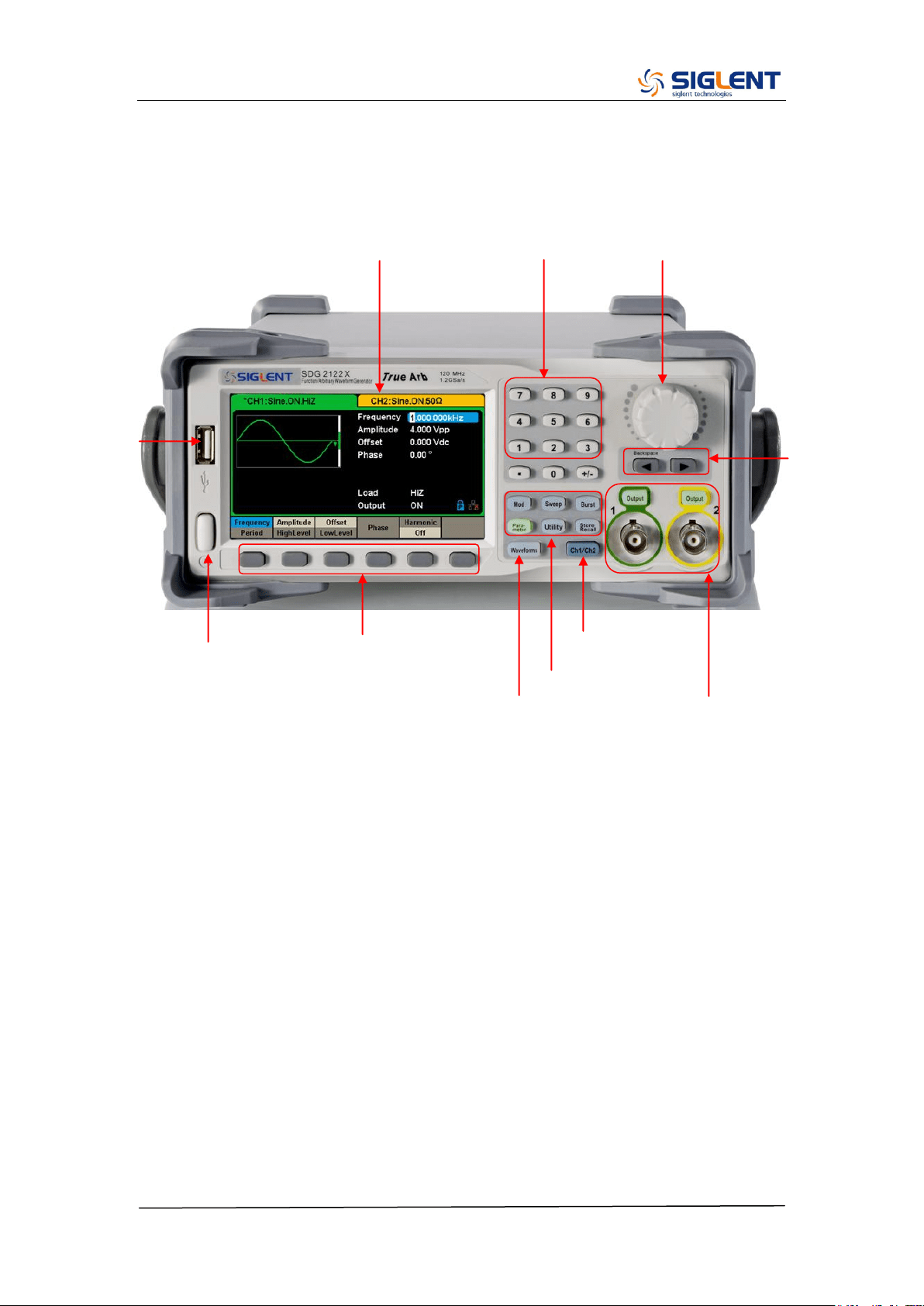
The Front Panel at a Glance
3. Touch Screen Display
10. Waveform Option
Area
4. Numeric Keyboard
5. Knob
1.Power Switch
11. Menu Keys
2.USB Host
6. Arrow Keys
7. CH1/CH2 Control/Output Port
9. Function Keys
8. Channel Select Key
SDG2000X Service Manual.doc
X
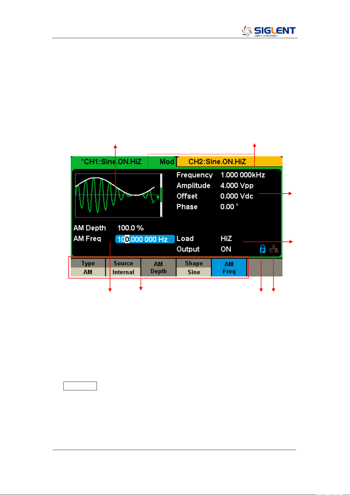
The User Interface at a Glance
SDG1000X can only display parameters and waveform for one channel at a
time. The picture below shows the interface when CH1 is selected and AM
modulation of a sine wave function is selected. The information displayed may
vary depending on the function selected.
1. Waveform Display Area
Displays the currently selected waveform of each channel.
2. Channel Status Bar
Indicates the selected status and output configuration of the channels.
3. Basic Waveform Parameters Area
Shows the current waveform‟s parameters for the selected channel. Press
Parameter and select the corresponding softkey to highlight the parameter
to configure. Then use number keys or knob to change the parameter
value.
4. Channel Parameters Area
Displays the load and output settings of the currently selected channel.
Load ----Value of the output load, as selected by the user.
4
3
8 7 6 5
1 2
SDG2000X Service Manual.doc
XI
Press Utility → Output → Load, then use the softkeys, number keys or
knob to change the parameter value; or continue pressing the
corresponding output key for two second to switch between High
Impedance and 50 Ω.
High Impedance: display HiZ.
Load: display impedance value (the default is 50 Ω and the range is 50 Ω to
100 kΩ).
Note: This setting does not actually change the instrument‟s output
impedance of 50 Ω but rather is used to maintain amplitude accuracy into
different load values.
Output ----Channel output state.
After pressing corresponding channel output control port, the current
channel can be turned on/off.
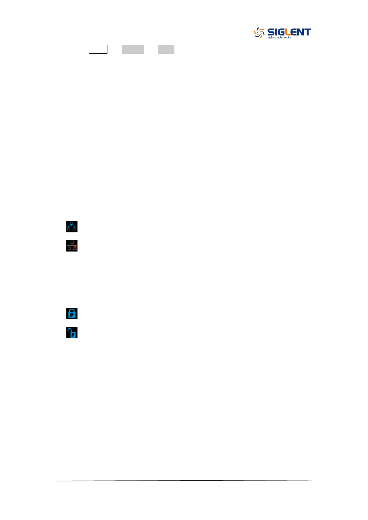
5. LAN Status Icon
The SDG2000X will show different prompt messages based on the current
network status.
This mark indicates LAN connection is successful.
This mark indicates there is no LAN connection or LAN connection is
unsuccessful.
6. Mode Icon
The SDG2000X will show different prompt messages based on the current
choosing status of the mode.
This mark indicates current mode is Phase-locked.
This mark indicates current mode is Independent.
7. Menu
Shows the menu corresponding to the displayed function. For example,
Figure 4 shows the parameters of “AM modulation”.
8. Modulation Parameters Area
Shows the parameters of the current modulation function. After selecting
the corresponding menu, use number keys or knob to change the
parameter value.
SDG2000X Service Manual.doc
XII
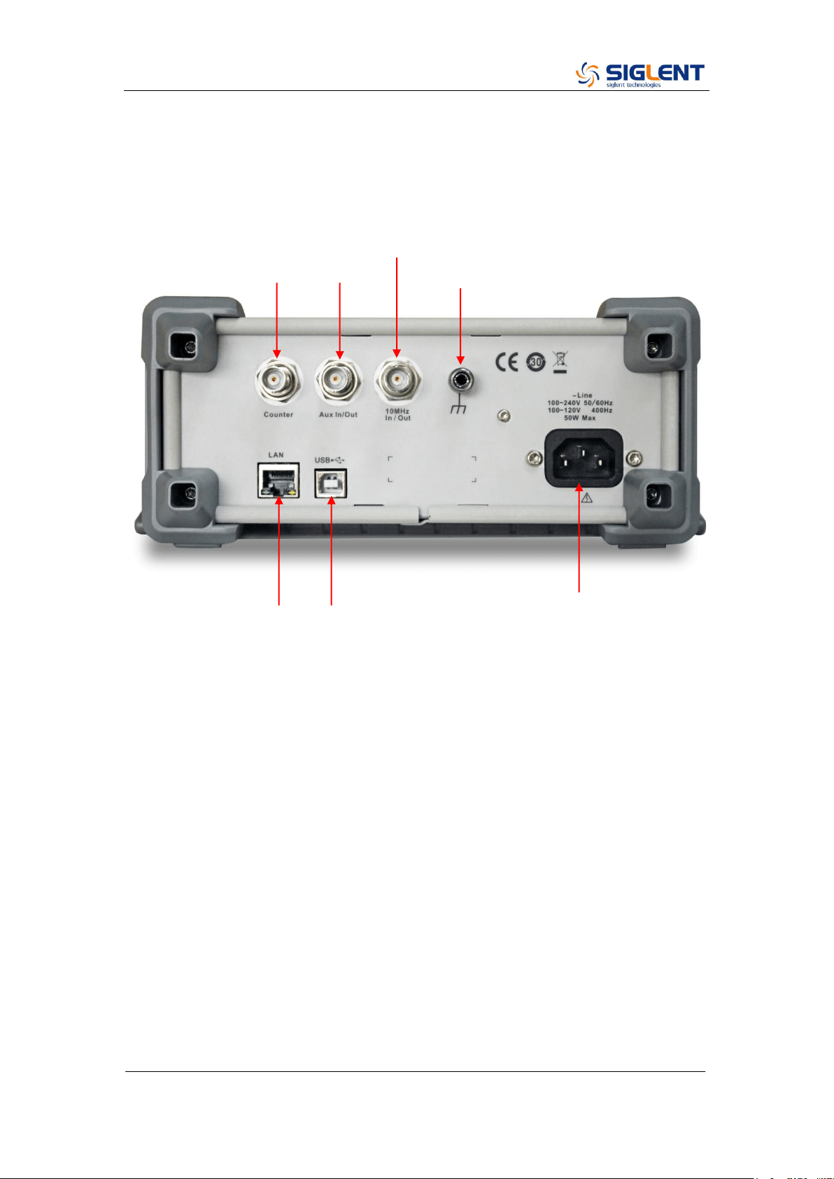
The Rear Panel at a Glance
WARNING: For protection from electric shock, the grounding power cord must
not be defeated. If only a two-contact electrical outlet is available, connect the
instrument’s chassis ground screw (see above) to a good earth ground.
Aux In/Out
10 MHz Clock Input/Output
Earth Terminal
LAN Interface
USB Device
AC Power Supply Input
Counter
Aux In/Out
SDG2000X Service Manual.doc
13
Chapter 1 Specifications
These specifications apply to the SDG2000X series Arbitrary Waveform
Generators. To verify that a generator meets the specifications, it must first
meet the following conditions:
The generator must have been operating continuously for thirty minutes
within the specified operating 18 ℃ ~ 28 ℃ temperature.
The generator must be within the factory calibration interval of one year.
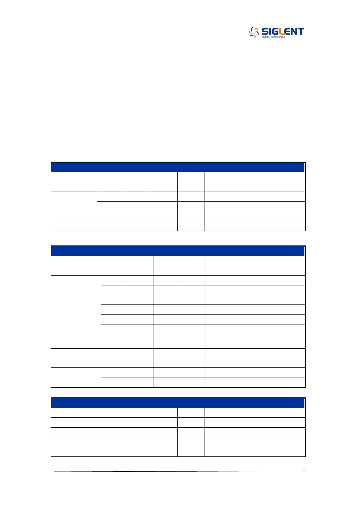
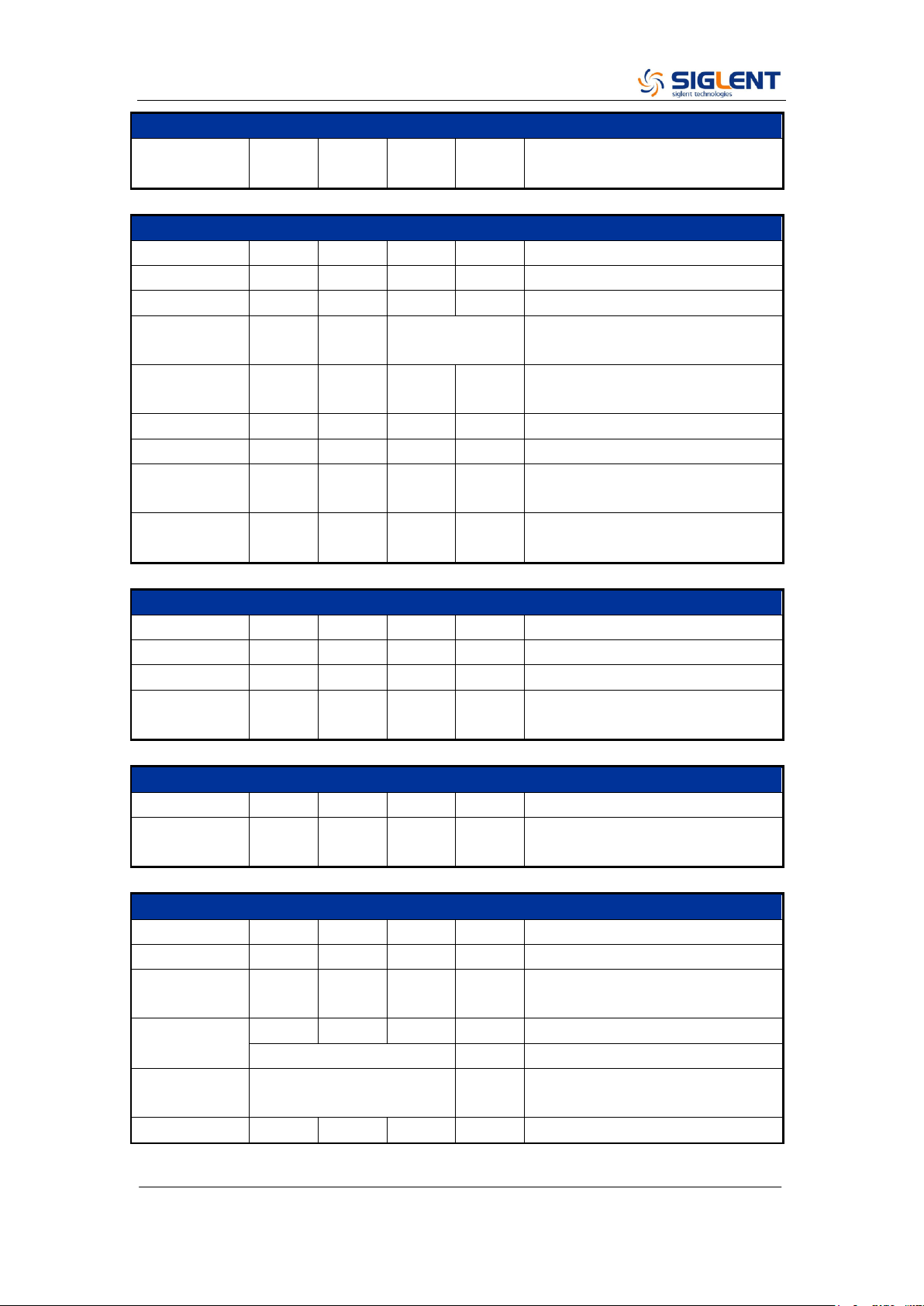
Frequency Characteristics
Parameter
Min.
Typ.
Max.
Unit
Condition
Resolution
1μ
Hz
Initial
accuracy
-1
+1
ppm
25 ℃
-2
+2
ppm
0~40 ℃
1
st
-year aging
-1
+1
ppm
25 ℃
10-year aging
-3.5
+3.5
ppm
25 ℃
Sine Characteristics
Parameter
Min.
Typ.
Max.
Unit
Condition
Frequency
1μ
120M
Hz
Harmonic
distortion
-65
dBc
0 dBm, 0~10 MHz (Included)
-60
dBc
0 dBm, 10~20 MHz (Included)
-55
dBc
0 dBm, 20~40 MHz (Included)
-50
dBc
0 dBm, 40~60 MHz (Included)
-45
dBc
0 dBm, 60~80 MHz (Included)
-40
dBc
0 dBm, 80~100 MHz (Included)
-38
dBc
0 dBm, 100~120 MHz (Included)
Total Harmonic
Distortion
0.075
%
0 dBm, 10 Hz ~ 20 kHz
Non-harmonic
spurious
-70
dBc
≤50 MHz
-65
dBc
>50 MHz
Square Characteristics
Parameter
Min.
Typ.
Max.
Unit
Condition
Frequency
1μ
25M
Hz
Rise/fall times
9
ns
10% ~ 90%, 1 Vpp, 50 Ω Load
Overshoot
3
%
100 kHz, 1 Vpp, 50 Ω Load
Duty cycle
0.001
99.999
%
Limited by frequency setting
SDG2000X Service Manual.doc
14
Square Characteristics
Jitter (rms),
Cycle to cycle
150
ps
1 Vpp, 50 Ω Load
Pulse Characteristics
Parameter
Min.
Typ.
Max.
Unit
Condition
Frequency
1μ
25M
Hz
Pulse width
16.3
ns
Pulse width
accuracy
±(0.01%+0.3ns)
Rise/fall times
8.4n
22.4
s
10% ~ 90%, 1 Vpp, 50 Ω Load,
Subject to pulse width limits
Overshoot
3
%
100 kHz, 1 Vpp
Duty cycle
0.001
99.999
%
Limited by frequency setting
Duty cycle
resolution
0.001
%
Jitter (rms)
cycle to cycle
150
ps
1 Vpp, 50 Ω Load
Ramp Characteristics
Parameter
Min.
Typ.
Max.
Unit
Condition
Frequency
1μ
1M
Hz
Symmetry
0
100
%
Linearity
1
%
Percentage of peak-peak output,
1 kHz, 1 Vpp, 100% symmetry
Noise Characteristics
Parameter
Min.
Typ.
Max.
Unit
Condition
-3dB
bandwidth
120
MHz
Arbitrary Wave Characteristics
Parameter
Min.
Typ.
Max.
Unit
Condition
Frequency
1μ
20M
Hz
Waveform
length
8
8M
pts
Sampling rate
1μ
75M
Sa/s
TrueArb mode
300
MSa/s
DDS mode
Vertical
solution
16
bit
Jitter (rms)
150
ps
1 Vpp, 50 Ω Load, TrueArb mode
SDG2000X Service Manual.doc
15
DC Characteristics
Parameter
Min.
Typ.
Max.
Unit
Condition
Range
-10
10
V
HiZ load
-5
5
V
50 Ω Load
Accuracy
±(1%+2 mV)
HiZ load
Output Characteristics
Parameter
Min.
Typ.
Max.
Unit
Condition
Range
(Note 1)
2m
20
Vpp
≤20 MHz, HiZ load
2m
10
Vpp
>20 MHz, HiZ load
Accuracy
±(1%+1mVpp)
10 kHz Sine, 0 V offset,
Amplitude
flatness
-0.3
+0.3
dB
0~100 MHz (Included), 50 Ω
Load, 2.5 Vpp, compare to 10
KHz Sine
-0.4
+0.4
dB
100~120 MHz (Included), 50 Ω
Load, 2.5 Vpp, compare to 10
KHz Sine
Output
impedance
49.5
50
50.5
Ω
10 KHz Sine
Output
current
-200
200
mA
Crosstalk
-60
dBc
CH1 - CH2, and CH2 - CH1
Note 1: The specification will be divided by 2 when applied to a 50 Ω Load.
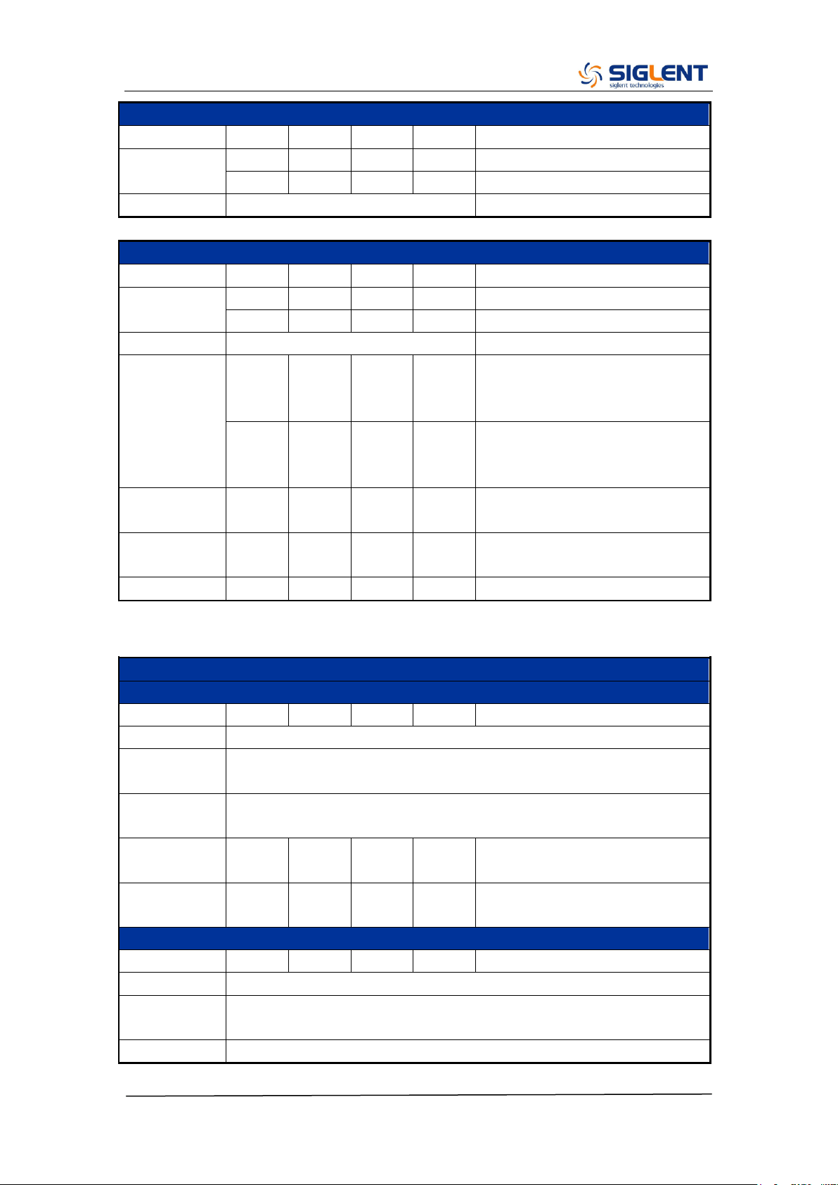
Modulation Characteristics
AM
Parameter
Min.
Typ.
Max.
Unit
Condition
Carrier
Sine, Square, Ramp, Arb
Modulation
Source
Internal/External
Modulating
wave
Sine, Square, Ramp, Noise, Arb
Modulation
depth
0
120
%
Modulation
frequency
1m
1M
Hz
While modulation source is
“Internal”
FM
Parameter
Min.
Typ.
Max.
Unit
Condition
Carrier
Sine, Square, Ramp, Arb
Modulation
Source
Internal/External
Modulating
Sine, Square, Ramp, Noise, Arb
SDG2000X Service Manual.doc
16
Modulation Characteristics
wave
Frequency
deviation
0
0.5*B
W
BW is the max. output frequency
Limited by frequency setting
Modulation
frequency
1m
1M
Hz
While modulation source is
“Internal”
PM
Parameter
Min.
Typ.
Max.
Unit
Condition
Carrier
Sine, Square, Ramp, Arb
Modulation
Source
Internal/External
Modulating
wave
Sine, Square, Ramp, Noise, Arb
Phase
deviation
0
360
°
Modulation
frequency
1m
1M
Hz
While modulation source is
“Internal”
ASK
Parameter
Min.
Typ.
Max.
Unit
Condition
Carrier
Sine, Square, Ramp, Arb
Modulation
Source
Internal/External
Modulating
wave
Square with 50% duty cycle
Keying
frequency
1m
1M
Hz
Limited by frequency setting
while modulation source is
“Internal”
FSK
Parameter
Min.
Typ.
Max.
Unit
Condition
Carrier
Sine, Square, Ramp, Arb
Modulation
Source
Internal/External
Modulating
wave
Square with 50% duty cycle
Modulation
frequency
1m
1M
Hz
While modulation source is
“Internal”
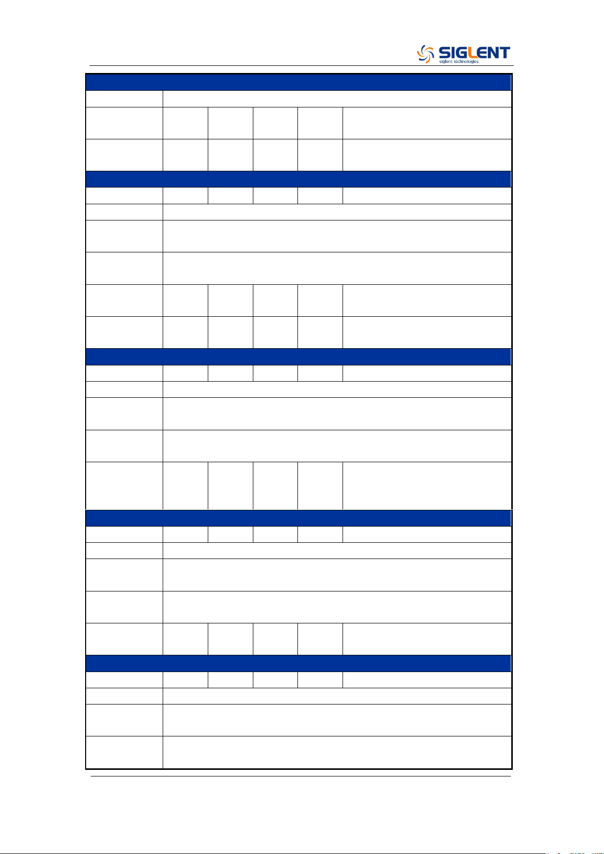
PWM
Parameter
Min.
Typ.
Max.
Unit
Condition
Carrier
Pulse
Modulation
Source
Internal/External
Modulating
wave
Sine, Square, Ramp, Noise, Arb
SDG2000X Service Manual.doc
17
Modulation Characteristics
Modulation
frequency
1m
1M
Hz
While modulation source is
“Internal”
Pulse width
deviation
resolution
6.67
ns
Burst Characteristics
Parameter
Min.
Typ.
Max.
Unit
Condition
Carrier
Sine, Square, Ramp, Pulse, Noise, Arb
Type
Count(1-1000000cycles), Infinite, Gated
Carrier
frequency
2m
BW
Hz
BW is the max. output frequency
Start/Stop
phase
0
360
°
Internal
period
1μ
1000
s
Trigger
source
Internal, External, Manual
Gated source
Internal /External
Trigger delay
100
s
Sweep Characteristics
Parameter
Min.
Typ.
Max.
Unit
Condition
Carrier
Sine, Square, Ramp, Arb
Type
Linear, Log
Direction
Up, Down
Carrier
frequency
1μ
BW
Hz
BW is the max. output frequency
Sweep time
1m
500
s
Trigger
source
Internal, External, Manual
Frequency Counter Characteristics
Parameter
Min.
Typ.
Max.
Unit
Condition
Function
Frequency, Period, Positive/Negative pulse width, Duty cycle
Coupling
mode
AC, DC, HFREJ
Frequency
range
100m
200M
Hz
DC coupling
10
200M
Hz
AC coupling
Input
amplitude
100mV
rms
±2.5 V
DC coupling, < 100 MHz
200mV
±2.5 V
DC coupling, 100 MHz ~ 200
SDG2000X Service Manual.doc
18
Frequency Counter Characteristics
rms
MHz
100mV
rms
5 Vpp
AC coupling, < 100 MHz
200mV
rms
5 Vpp
AC coupling, 100 MHz ~ 200
MHz
Input
impedance
1M
Ω
Reference Clock Input/Output
Reference Clock Input
Parameter
Min.
Typ.
Max.
Unit
Condition
Frequency
10M
Hz
Amplitude
1.4
Vpp
Input
impedance
5
kΩ
AC coupling
Reference Clock Output
Parameter
Min.
Typ.
Max.
Unit
Condition
Frequency
10M
Hz
Synchronized to internal
reference clock
Amplitude
2
3.3
Vpp
HiZ load
Output
impedance
50
Ω
Auxiliary In/Out Characteristics
Trigger Input
Parameter
Min.
Typ.
Max.
Unit
Condition
V
IH
2
5.5
V
V
IL
-0.5
0.8
V
Input
impedance
100
kΩ
Pulse width
100
ns
Response
time
100
ns
Sweep
600
ns
Burst
Trigger Output
Parameter
Min.
Typ.
Max.
Unit
Condition
V
OH
3.8
V
I
OH
= –8 mA
V
OL
0.44
V
I
OL
= 8 mA
Output
impedance
100
Ω
Frequency
1
MHz
Sync Output
Parameter
Min.
Typ.
Max.
Unit
Condition
SDG2000X Service Manual.doc
19
Auxiliary In/Out Characteristics
V
OH
3.8
V
I
OH
= –8 mA
V
OL
0.44
V
I
OL
= 8 mA
Output
impedance
100
Ω
Pulse width
500
ns
Frequency
1
MHz
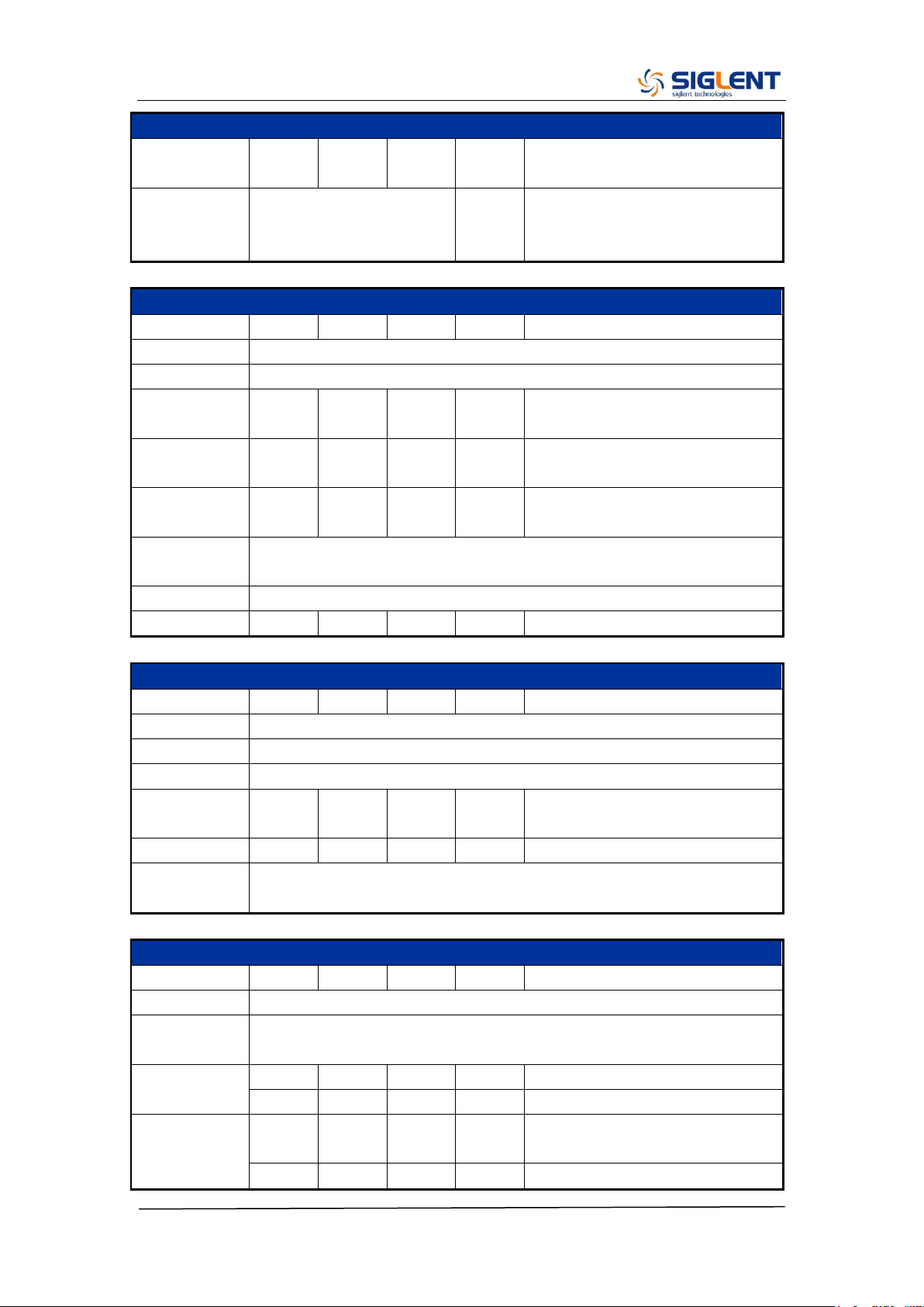
Modulation Input
Parameter
Min.
Typ.
Max.
Unit
Condition
Frequency
0
50
kHz
Input
impedance
10
kΩ
Amplitude@
100%
Modulation
depth
11
12
13
Vpp
General Characteristics
Power
Parameter
Min.
Typ.
Max.
Unit
Condition
Voltage
100 - 240 Vrms (± 10%), 50 / 60 Hz
100 - 120 Vrms (± 10%), 400 Hz
Power
consumption
25.5
50
W
Dual channels, Sine, 1 kHz, 10
Vpp, 50 Ω load
Display
Parameter
Min.
Typ.
Max.
Unit
Condition
Color depth
24
bit
Contrast ratio
350:1
Luminance
300
cd/m
2
Touch panel
type
Resistive
Environment
Parameter
Min.
Typ.
Max.
Unit
Condition
Operating
temperature
0
40
℃
Storage
temperature
-20
60
℃
Operating
humidity
5
90
%
≤ 30 ℃
5
50
%
40 ℃
Non-operatin
g humidity
5
95
%
Operating
altitude
3048
m
≤ 30 ℃
SDG2000X Service Manual.doc
20
General Characteristics
Non-operatin
g altitude
15000
m
Calibration
Parameter
Min.
Typ.
Max.
Unit
Condition
Calibration
interval
1
year
Mechanical
Parameter
Min.
Typ.
Max.
Unit
Condition
Dimensions
W×H×D = 260.3mm×107.2mm×295.7mm
Net weight
3.43
kg
Gross weight
4.42
kg
Compliance
LVD
IEC 61010-1:2010
EMC
EN61326-1:2013

SDG2000X Service Manual.doc
21
Chapter 2 Quick Start
One of the first things you will want to do with your generator is to become
acquainted with the front panel. We have written the exercises in this chapter
to prepare the instrument for use and help you get familiar with some of its
front-panel operations. This chapter is divided into the following sections:
To Prepare the Generator for Use
To Adjust the Carrying Handle
To Set the Output Frequency
To Set the Output Amplitude
To Set a DC Offset Voltage
To Set the Duty Cycle of a Square Waveform
To Set the Symmetry of a Ramp Waveform
To Configure a Pulse Waveform
To Configure a Noise Waveform
To Set the DC Voltage
To Output a Built-In Arbitrary Waveform
To Use the Built-In Help System

SDG2000X Service Manual.doc
22
To Prepare the Generator for Use
1. Check the list of accessories
Accessories supplied with the instrument are listed below. If anything is
missing or damaged, please contact your nearest SIGLENT Sales Office.
A Quick Start
A Certification
A Guaranty Card
A CD (EasyWave software, Datasheet and User Manual)
A power cord designed for use in the destination country
A USB cable
A BNC cable
2. Connect the power cord and turn on the generator
The instrument runs a short power-on self-test, which takes several seconds.
The generator powers up in the sine wave function at 1 kHz with an amplitude
of 4 V peak-to-peak (CH1). At power-on, the Output connector is disabled. To
enable the Output connector, press the Output key.
If the generator does not turn on, verify that the power cord is firmly connected
to the power socket on the rear panel (the power-line voltage is automatically
sensed at power-on). Also, make sure that the generator is connected to a
power source that is energized.
Then, verify that the generator is turned on.
Note: If the power-on self-test fails, the generator may stop and display a black
screen. For solutions, please contact the nearest SIGLENT sales office or
return the generator to SIGLENT for service.
SDG2000X Service Manual.doc
23
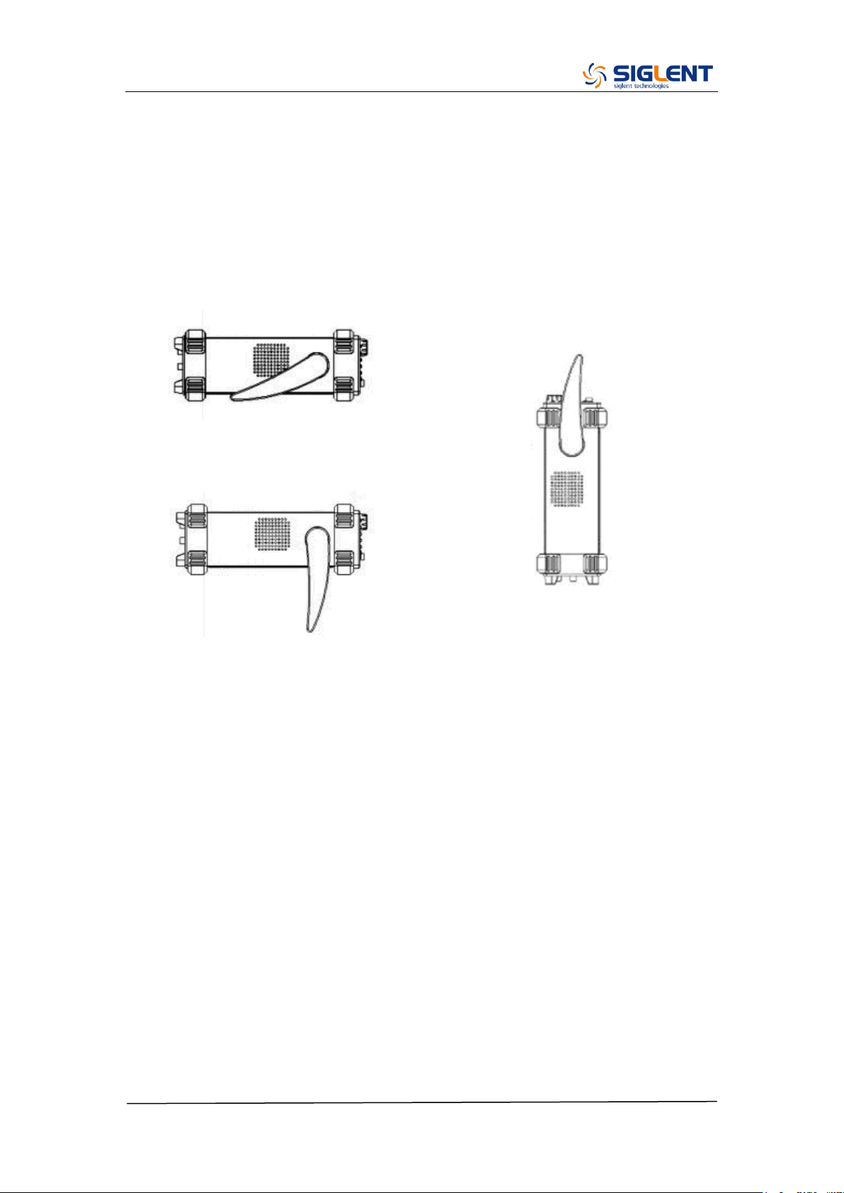
To Adjust the Carrying Handle
To adjust the position, grasp the handle by the sides and pull outward. Then,
rotate the handle to the desired position.
Pull the handle ahead for easy carrying
Pull the handle down
SDG2000X Service Manual.doc
24
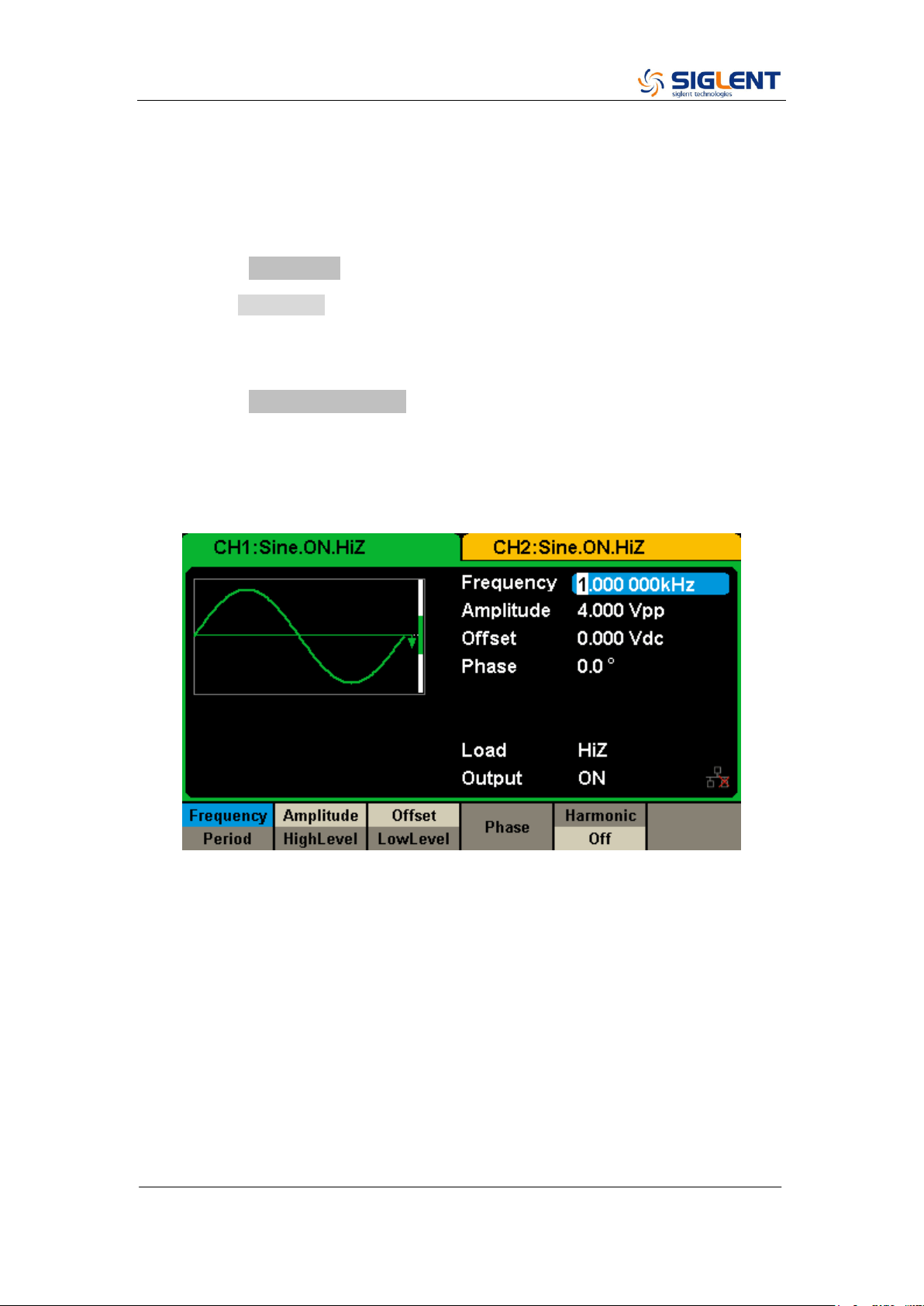
To Set the Output Frequency
The following steps explain change the frequency to 20 KHz.
1. Press the Parameter softkey
Press the Parameter softkey to enter the parameter set interface. The
waveform parameters including Frequency/Period, Amplitude/HighLevel,
Offset/LowLevel and Phase are ready to modify using the numeric keypad.
2. Press the Frequency/Period softkey
The displayed frequency is either the power-on value or the frequency
previously selected. When changing the function, the same frequency is used
if the current value is valid for the new waveform. To set the period, press the
softkey again to switch to the period parameter
3. Input the desired frequency
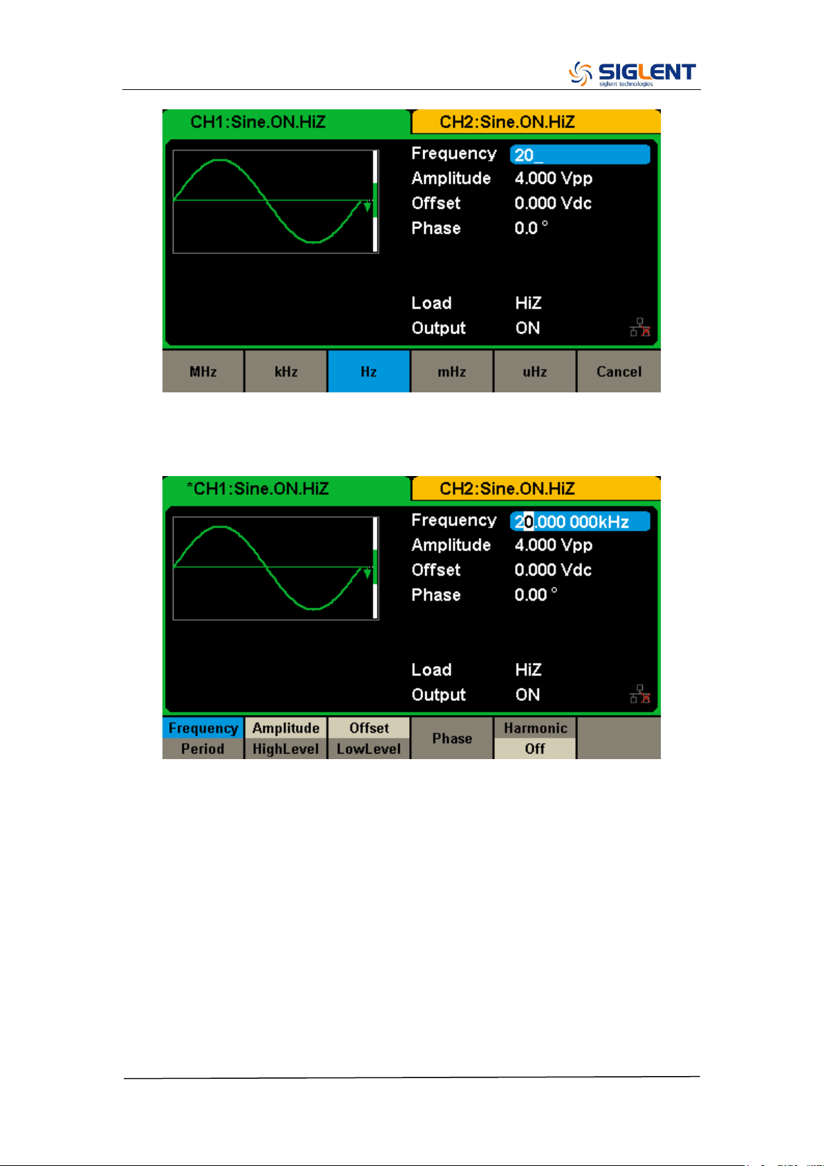
Use the digital keypad to input the value directly, enter the value “20”.
SDG2000X Service Manual.doc
25
Then press the corresponding softkey to select the desired unit. For example,
press kHz.
Note: The desired numerical value can be modified using the knob and
direction keys.
SDG2000X Service Manual.doc
26
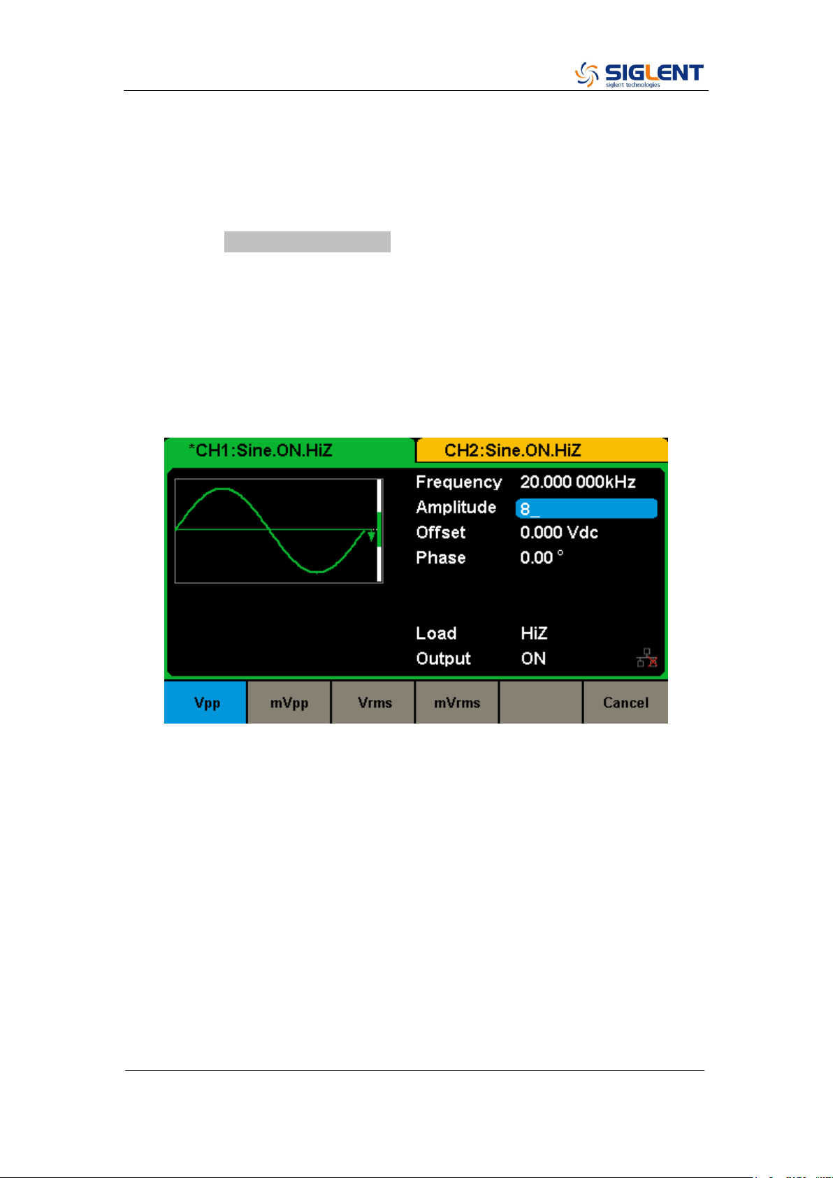
To Set the Output Amplitude
The following steps describe how to change the amplitude to 8 Vpp.
1. Press the Amplitude/HighLevel softkey
The displayed amplitude is either the power-on value or the amplitude
previously selected. When changing the function, the same amplitude is used
if the current value is valid for the new waveform. To set the HighLevel for the
waveform, press the softkey again to switch to the HighLevel parameter.
2. Input the desired amplitude
Use the digital keypad to input the value directly, enter the value “8”.
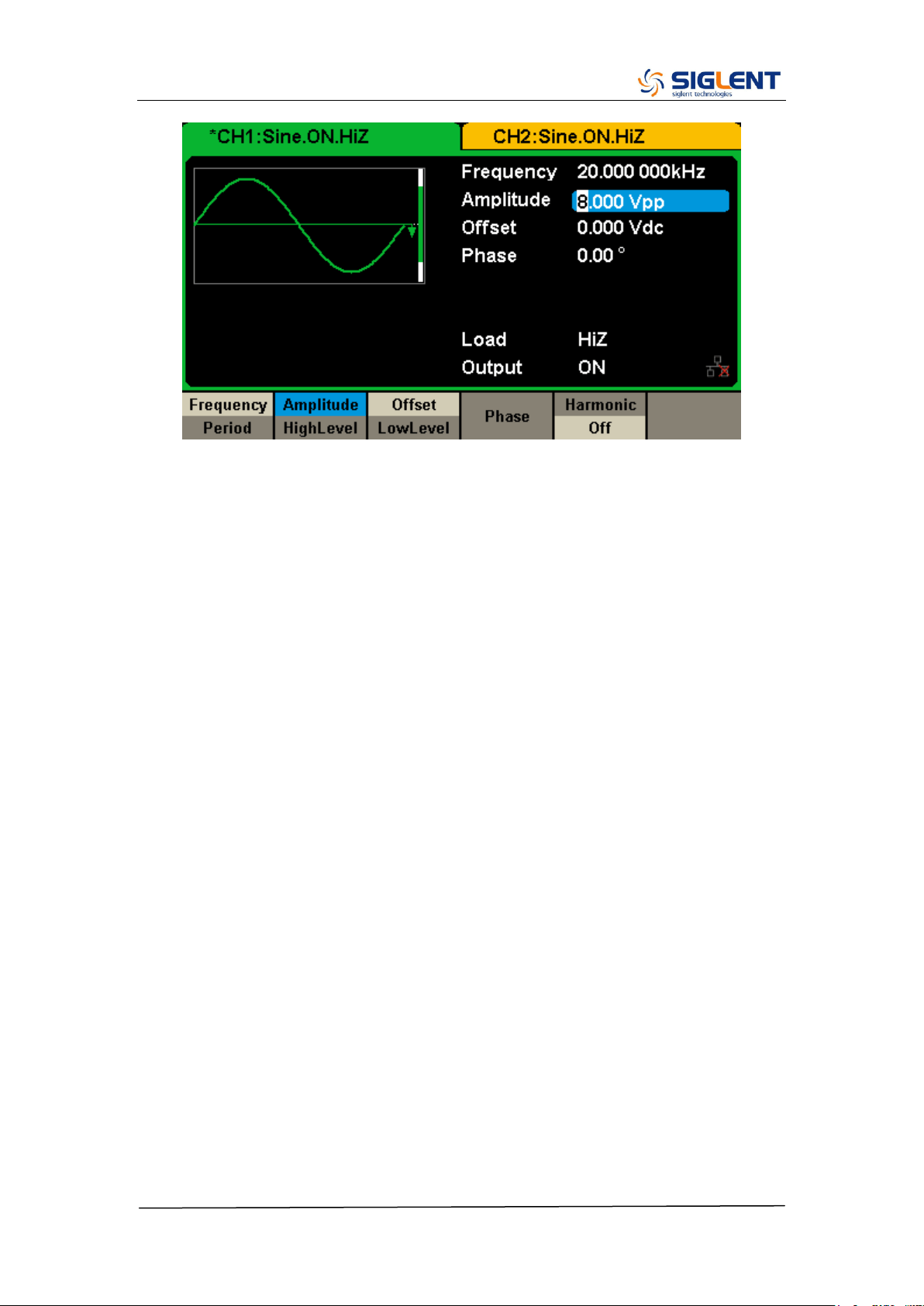
Then press the corresponding softkey to select the desired unit. For example,
press Vpp.
SDG2000X Service Manual.doc
27
SDG2000X Service Manual.doc
28
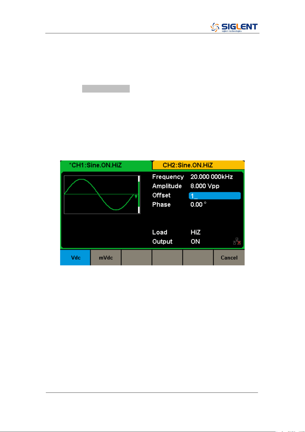
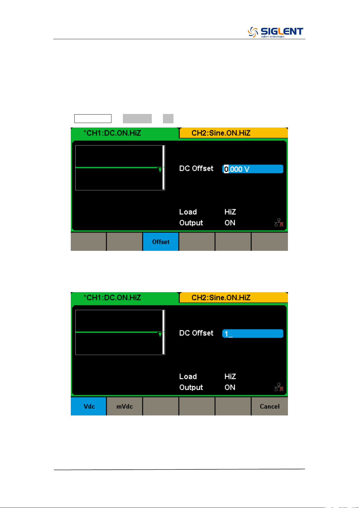
To Set the DC offset
The following steps describe how to change offset to 1 Vdc.
1. Press the Offset/LowLevel softkey
The displayed offset is either the power-on value or the offset previously
selected. When changing the function, the same offset is used if the current
value is valid for the new waveform. To set the LowLevel for the waveform,
press the softkey again to switch to the LowLevel parameter.
2. Input the desired offset
Use the digital keypad to input the value directly, enter the value “1”.
Then press the corresponding softkey to select the desired unit. For example,
press Vdc.

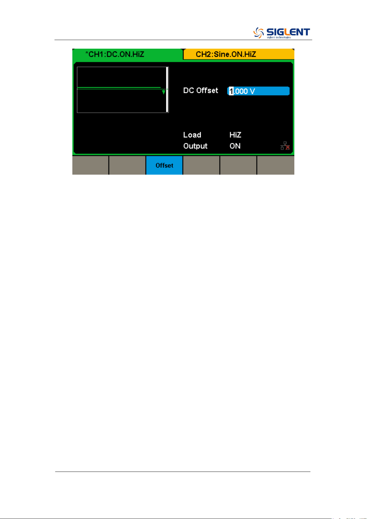
SDG2000X Service Manual.doc
29
Note: The desired numerical value can be modified using the knob and
direction keys.
SDG2000X Service Manual.doc
30
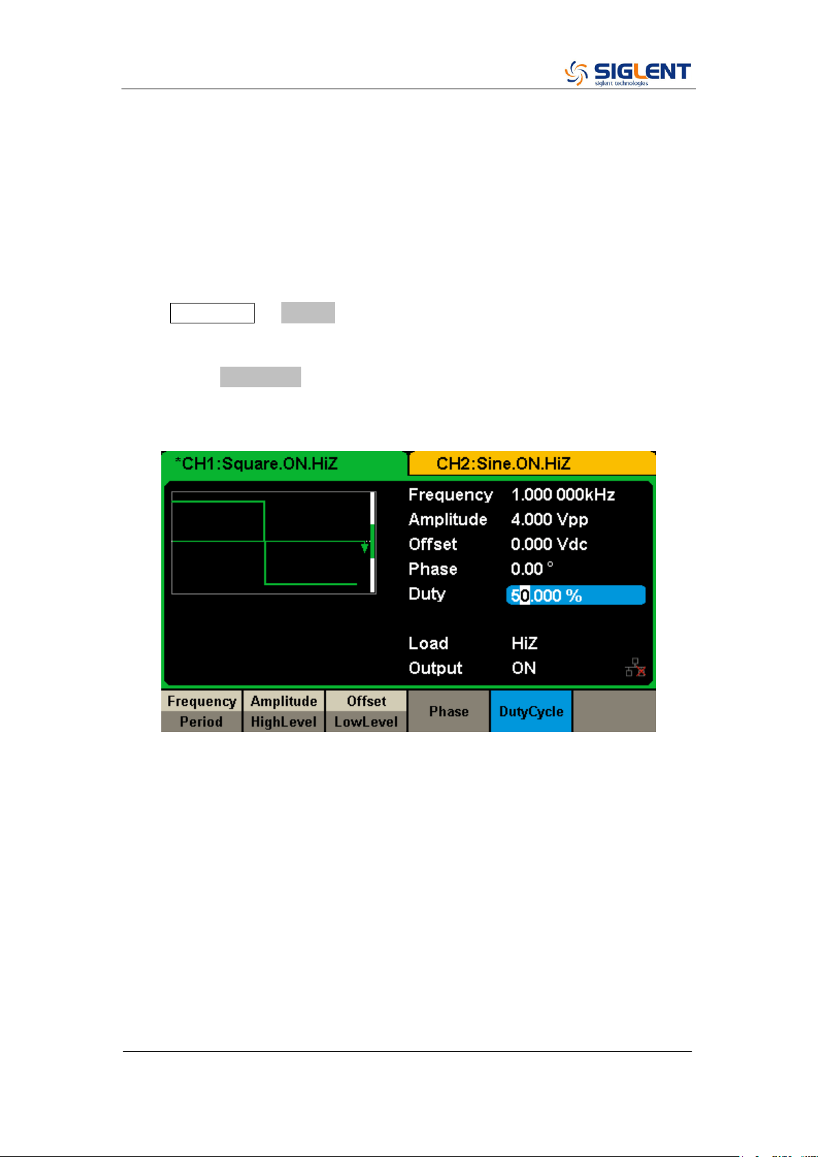
To Set the Duty Cycle of a Square Waveform
At power-on, the default duty cycle for square wave is 50%. The duty cycle
setting range is limited by the “Frequency/Period” setting. The following steps
show how to change the duty cycle to 80%.
1. Select the square wave function
Press Waveforms → Square to select the square function and then select the
desired output frequency to 1 kHz.
2. Press the DutyCycle softkey
The displayed duty is either the power-on value or the percentage previously
selected.
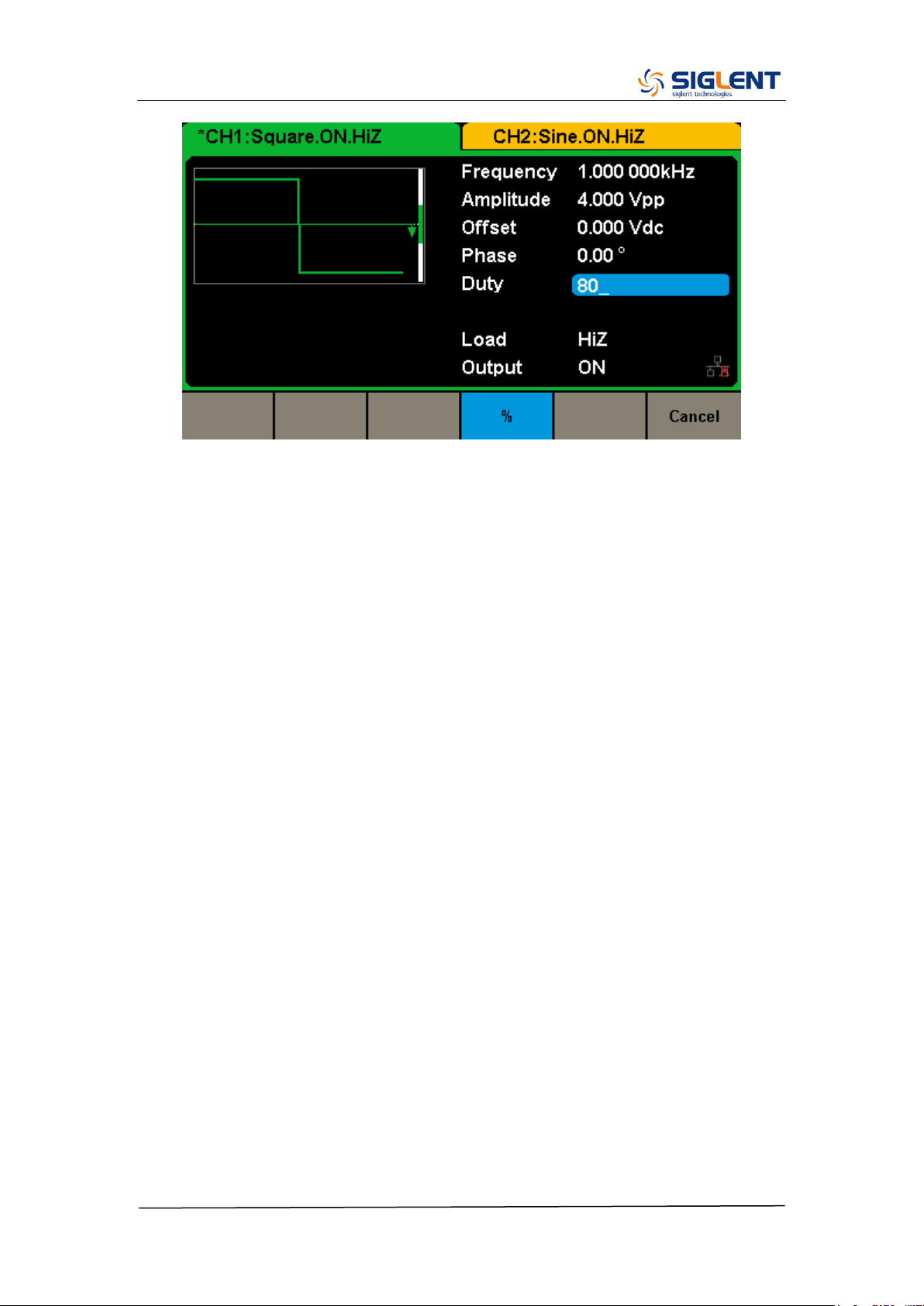
3. Input the desired duty
Use digital keypad to input the value directly, enter the value “80”, then press
the corresponding softkey to select the desired unit “%”.
SDG2000X Service Manual.doc
31
SDG2000X Service Manual.doc
32
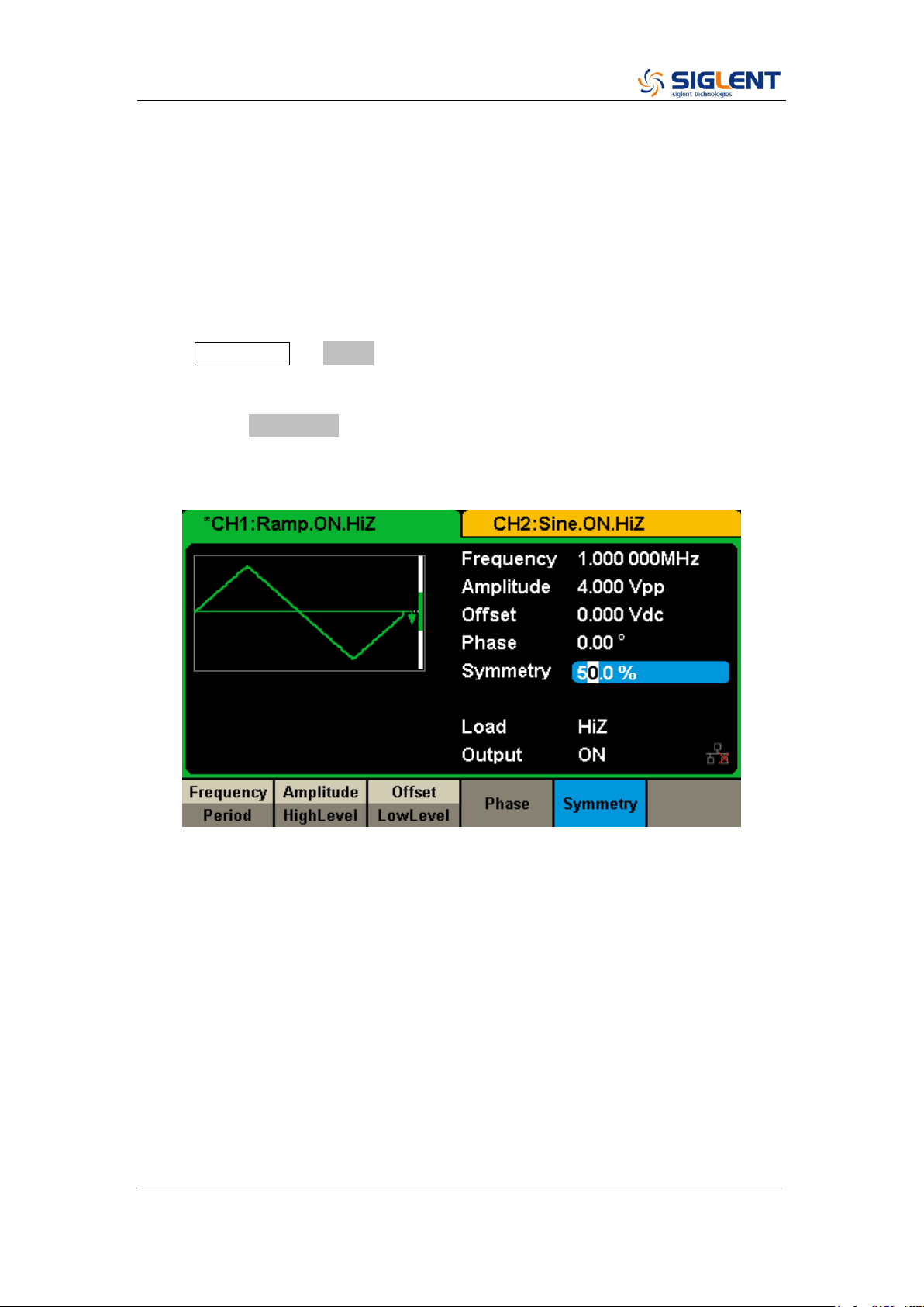
To Set the Symmetry of a Ramp Waveform
At power-on, the Symmetry for Ramp wave is 50%. The symmetry can be
adjusted between 0% and 100%. The following steps describe the procedure
to set the symmetry to 60%.
1. Select the Ramp wave function
Press Waveforms → Ramp to select the pulse function and then select the
desired output frequency to 1 MHz.
2. Press the Symmetry softkey
The displayed symmetry is either the power-on value or the percentage
previously selected.
3. Input the desired symmetry
Use digital keypad to input the value directly, enter the value “60”, then press
the corresponding softkey to select the desired unit “%”.

SDG2000X Service Manual.doc
33
SDG2000X Service Manual.doc
34
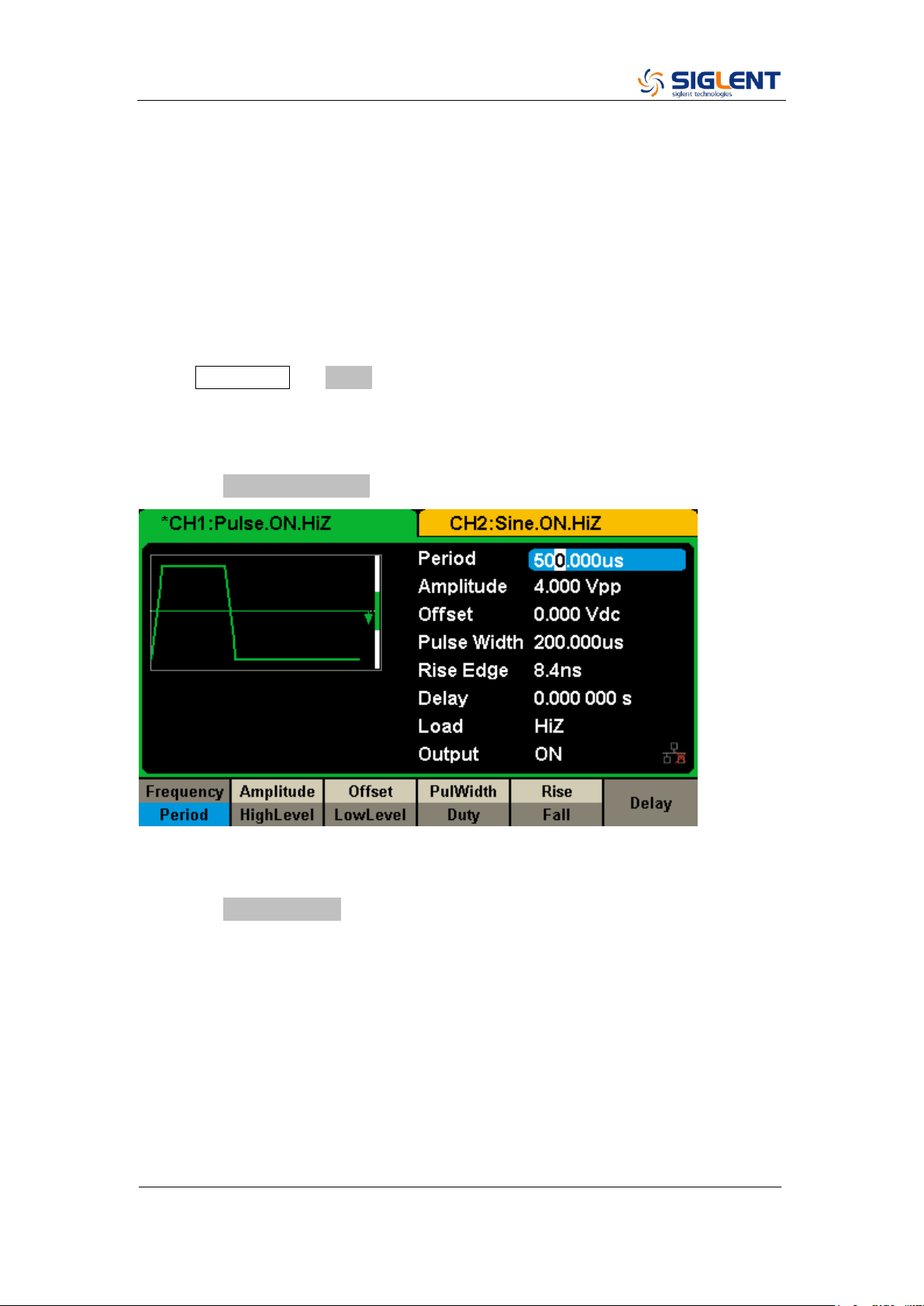
To Generate a Pulse Waveform
The generator can be set to output a pulse waveform with variable width, edge
time and delay time. The following steps show you how to generate a 500 µs
period pulse waveform with a pulse width of 100 µs, rise time of 8 ns and delay
time of 50 ns.
1. Select the pulse function
Press Waveforms → Pulse to select the pulse function and output a pulse
waveform with the default parameters.
2. Set the Pulse period
Press the Frequency/Period softkey twice and then set the period to 500 µs.
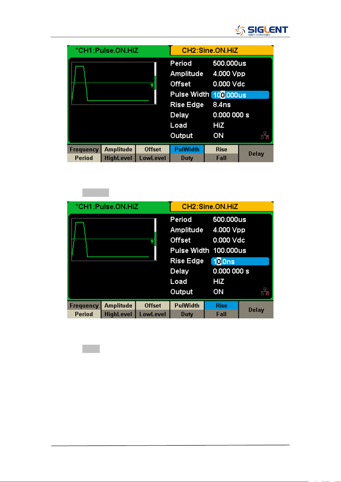
3. Set the Pulse Width
Press the PulWidth/Duty softkey and then set the pulse width to 100 µs. The
pulse width represents the time from the 50% threshold of the rising edge to
the 50% threshold of the next falling edge.
SDG2000X Service Manual.doc
35
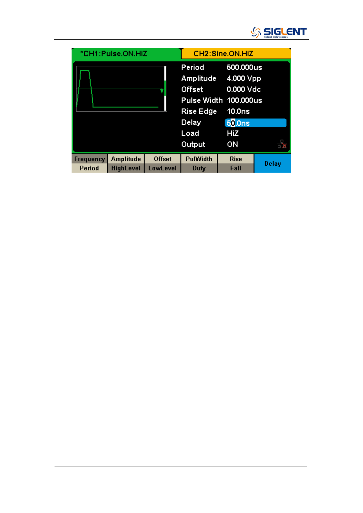
4. Set the Edge Time
Press the Rise/Fall softkey and then set the rising edge to 10 ns.
5. Set the Pulse Delay
Press the Delay softkey and then set the delay time to 50 ns.
SDG2000X Service Manual.doc
36
SDG2000X Service Manual.doc
37
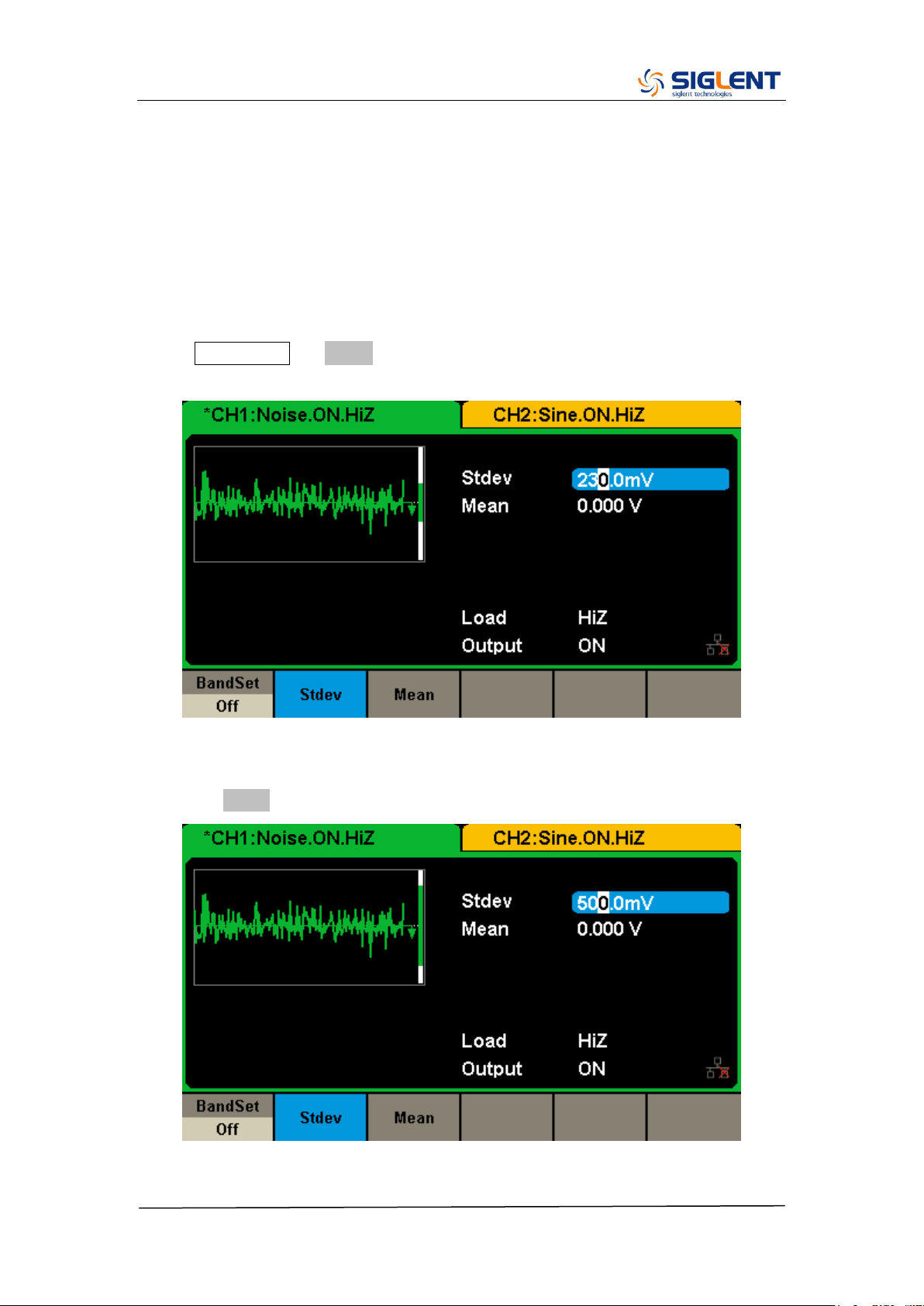
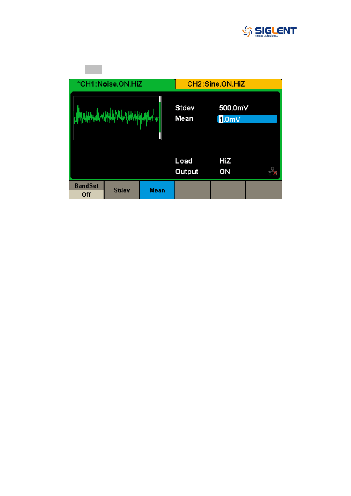
To Generate a Noise Waveform
The generator can be set to output a noise waveform with an adjustable Stdev
and Mean. The following steps show you how to generate a noise waveform
with 500 mV Stdev and 1 mV Mean.
1. Select the Noise function
Press Waveforms → Noise to select the noise function and output a noise
waveform with the default parameters.
2. Set the Stdev
Press the Stdev softkey and then set the Stdev to 500 mV.
SDG2000X Service Manual.doc
38
3. Set the Mean
Press the Mean softkey and then set the mean to 1 mV.
SDG2000X Service Manual.doc
39
To Set the DC Voltage
The following steps show how to set a dc voltage with +1 Vdc.
1. Select the DC function
Press Waveforms → Page 1/2 → DC to select the DC function.
2. Set the DC Offset
Use the digital keypad to input the value directly, enter the value “1”.
Then press the corresponding softkey to select the desired unit. For example,
press Vdc.
SDG2000X Service Manual.doc
40
SDG2000X Service Manual.doc
41
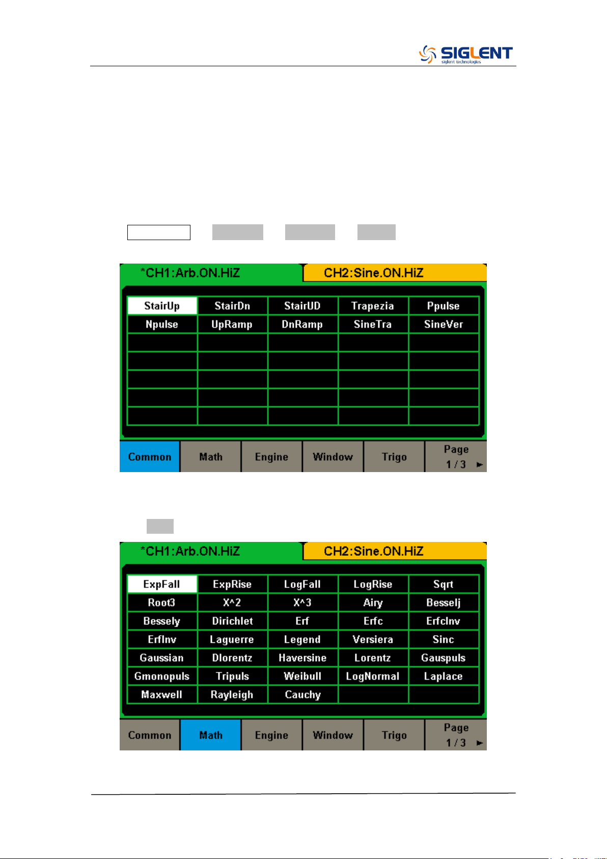
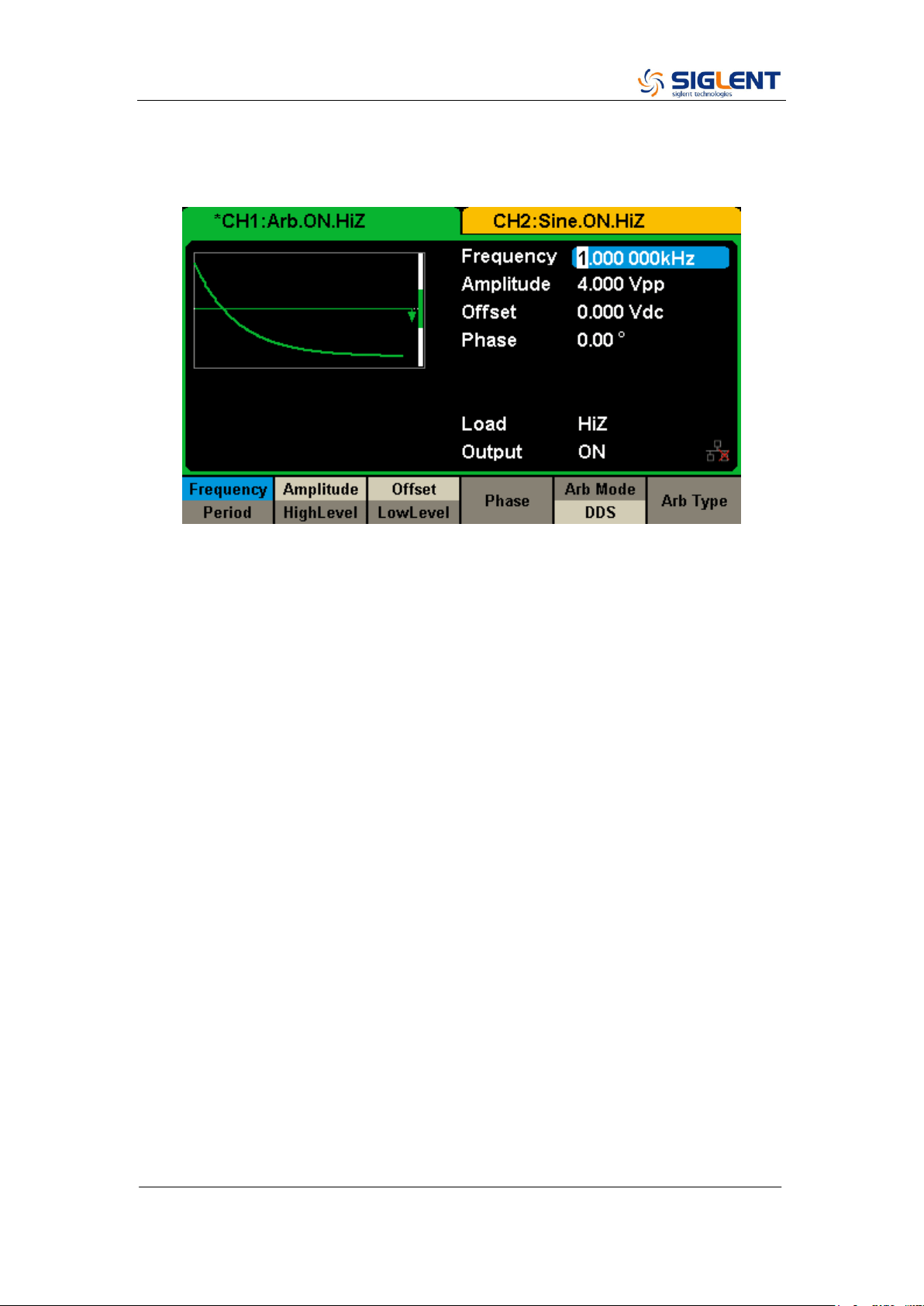
To Output a Built-In Arbitrary Waveform
There are approximately 200 built-in arbitrary waveforms stored in non-volatile
memory. The following steps show how to output the built-in “exponential fall”
waveform from the front panel.
1. Set the arbitrary waveform function
Press Waveforms → Page 1/2 → Arb Type → Built-In to enter the arbitrary
waveform setting interface.
2. Set the Math waveform
Press the Math softkey to display the mathematic waveform as below.
SDG2000X Service Manual.doc
42
3. Output the exponential fall waveform
Rotate the knob to select the ExpFall waveform and press the knob. The
waveform is output with the present settings unless they are changed.
SDG2000X Service Manual.doc
43
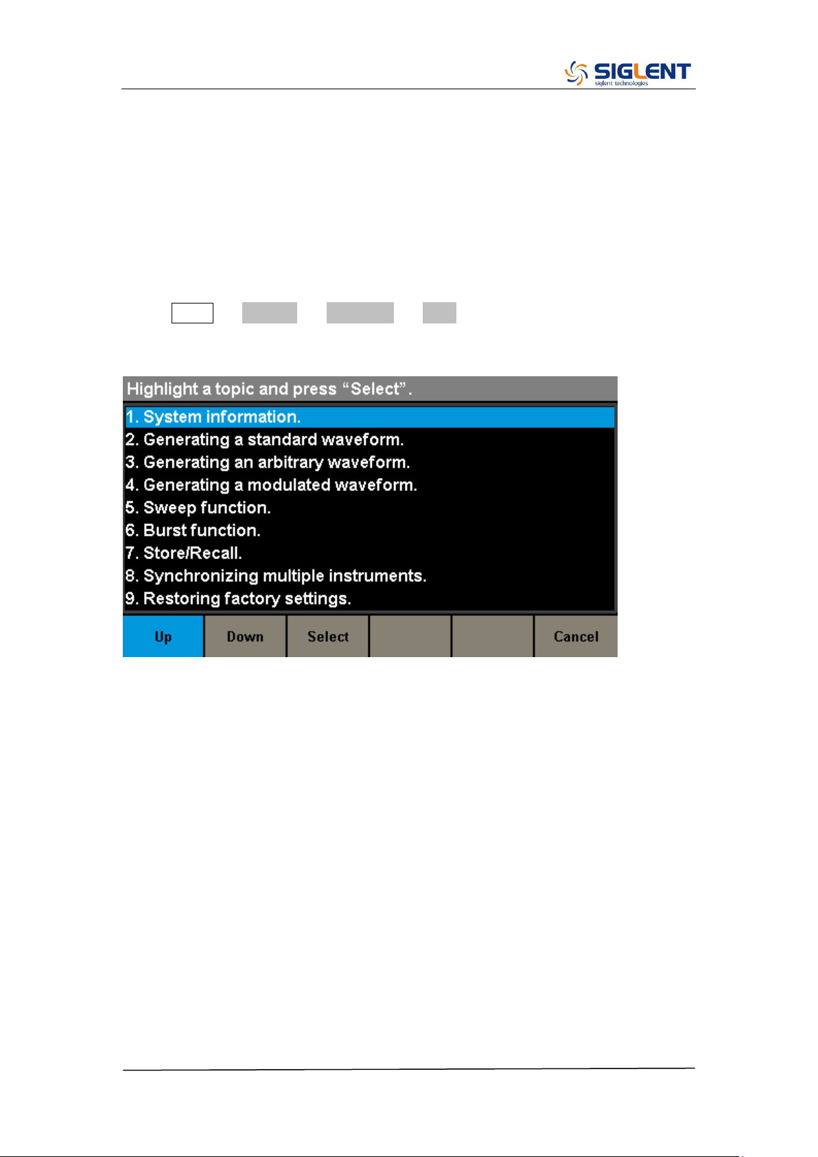
To Use the Built-In Help System
The built-in help system is designed to provide context-sensitive assistance of
some functions. A list of help topics is also available to assist you with several
operations.
1. Read the help information
Press Utility → System → Page 1/2 → Help to enter the following interface.
You will see a list of help topics as below. Use Up and Down keys, then press
Select to choose a Help topic.
2. Press “Cancel” or any function button to exit the help system

SDG2000X Service Manual.doc
44
Chapter 3 Calibration
This calibration procedure contains performance verification procedures and
adjustment procedures. After receiving a generator, it is recommended to first
confirm that the performance is related to the specifications. If so, then perform
the appropriate adjustments.
Calibration Interval
The instrument should be calibrated on a regular interval determined by the
measurement accuracy requirements of your application. A 1-year interval is
adequate for most applications. Accuracy specifications will remain valid only if
adjustment is made at regular calibration intervals. Accuracy specifications are
not valid beyond the1-year calibration interval. SIGLENT does not recommend
extending calibration intervals beyond 2 years for any application.
Adjustment is Recommended
Specifications are valid only within the period from the last adjustment.
Whatever calibration interval you select, SIGLENT recommends that
re-adjustment should always be performed within the calibration interval. This
is necessary to ensure the accuracy of the performance data measured during
the calibration interval.
Automating Calibration Procedures
The complete verification and adjust procedures can be automated with the
use of appropriate automated test instrumentation. The complete instrument
configurations specified for each test may be programmed via the remote
interface. Verification data can then be read-back from the instrument into a
test program and compared to the appropriate test limit values.
The instrument can also be adjusted from the remote interface. Remote
adjustment is similar to the local front-panel procedure. A PC can be used to
perform the adjustment by first selecting the required function and range. The
adjustment command is sent to the instrument and then the adjustment is
initiated over the remote interface.
Recommended Test Equipment
The test equipment instrumentation recommended for the performance
verification and adjustment procedures is listed below. If the exact instrument

SDG2000X Service Manual.doc
45
is not available, substitute with the instrument of equivalent accuracy.
Instrument
Requirements
Recommended Model
Digital Multimeter (DMM)
DC volts
accuracy: 100 ppm
resolution: 100 μV
Agilent 34401A
Power Meter
Frequency:
10 KHz to 50 MHz
Agilent U2004
GPIB cable
GPIB(IEEE488)
Frequency Counter
Accuracy: 0.5 ppm
Test Considerations
For optimum performance, all procedures should comply with the following
recommendations:
Updating SDG‟s firmware to the newest version is strongly recommended.
Assure that the calibration ambient temperature is stable and between
18℃ and 28℃. Ideally, the calibration should be performed at 23℃±1℃.
Assure ambient relative humidity is less than 80%.
Allow a 30 minute warm-up period before verification or adjustment.
Keep the measurement cables as short as possible, consistent with the
impedance requirements.
Use a 50 Ω coaxial cable.
Performance Verification Test
The performance verification tests are recommended as acceptance tests
upon receipt of the instrument. The acceptance test results should be
compared against the specifications given in chapter 1. After acceptance,
repeat the performance verification tests at every calibration interval.
If the instrument fails performance verification, adjustment or repair is required.
SDG2000X Service Manual.doc
46
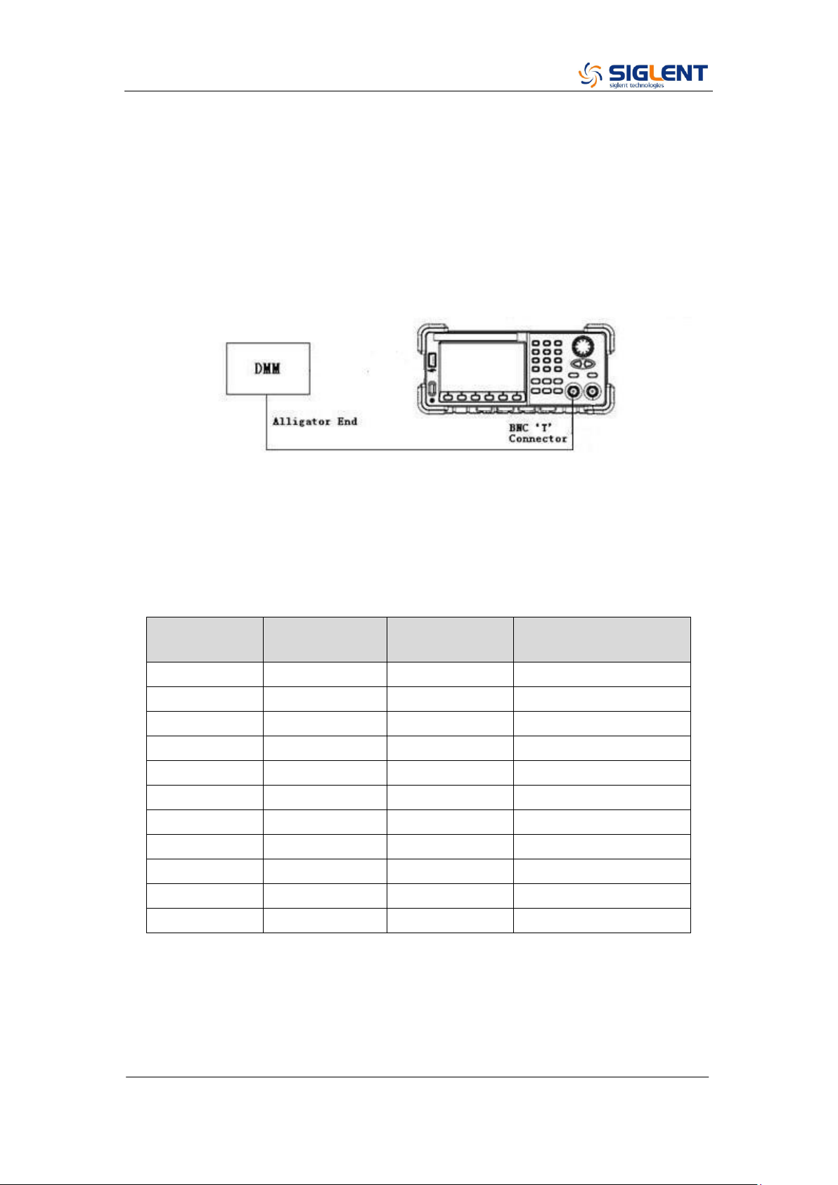
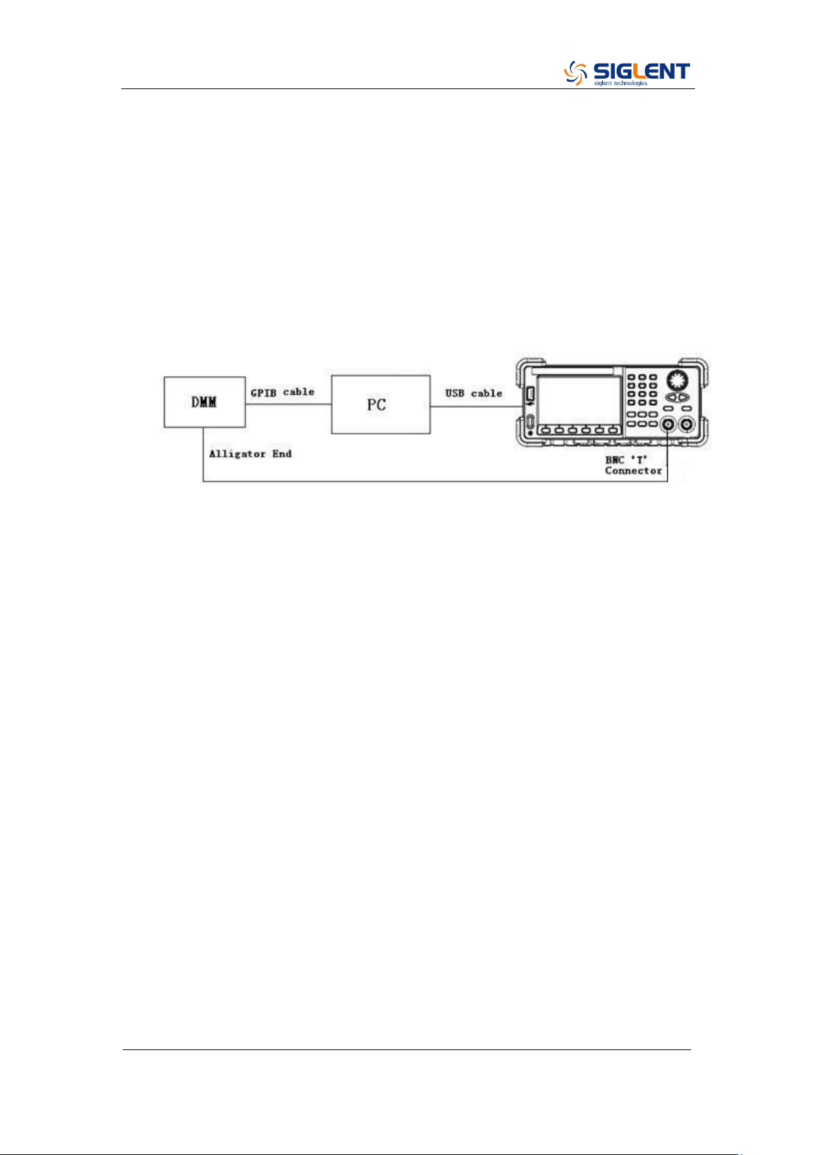
DC Output Verification
This test checks if the DC offset listed in the table below are within the spec
range using a DMM.
1. Set the DMM to measure DC voltage. Connect the DMM to the CH1 output
of the generator as shown below.
2. Turn on CH1 and select the DC waveform.
3. Set the instrument to each output value described in the table below and
measure the output voltage with the DMM. Be sure the generator output load
is set to High–Z and the output is enabled.
DC Offset
CH1
CH2
Spec Range
± (1%+2 mV)
0 mV
-2 mV ~ 2 mV
10 mV
7.9 mV ~ 12.1 mV
100 mV
97 mV ~ 103 mV
1 V
0.988 V ~ 1.012 V
3 V
2.968 V ~ 3.032 V
10 V
9.898 V ~ 10.102 V
-10 mV
-12.1 mV ~ - 7.9 mV
-100 mV
-103 mV ~ -97 mV
-1 V
-1.012 V ~ -0.988 V
-3 V
-3.032 V ~ -2.968 V
-10 V
10.102 V ~ -9.898 V
4. Compare the measured voltage to the spec range shown in the table above.
SDG2000X Service Manual.doc
47
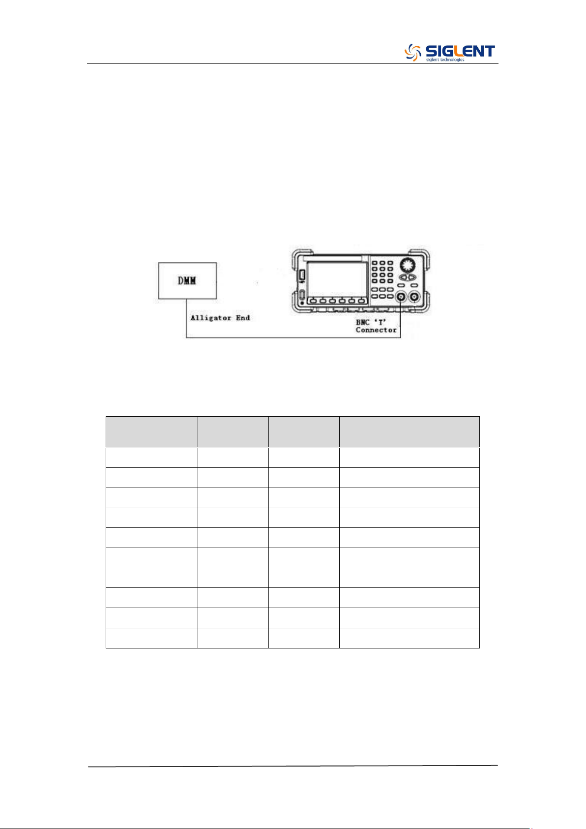
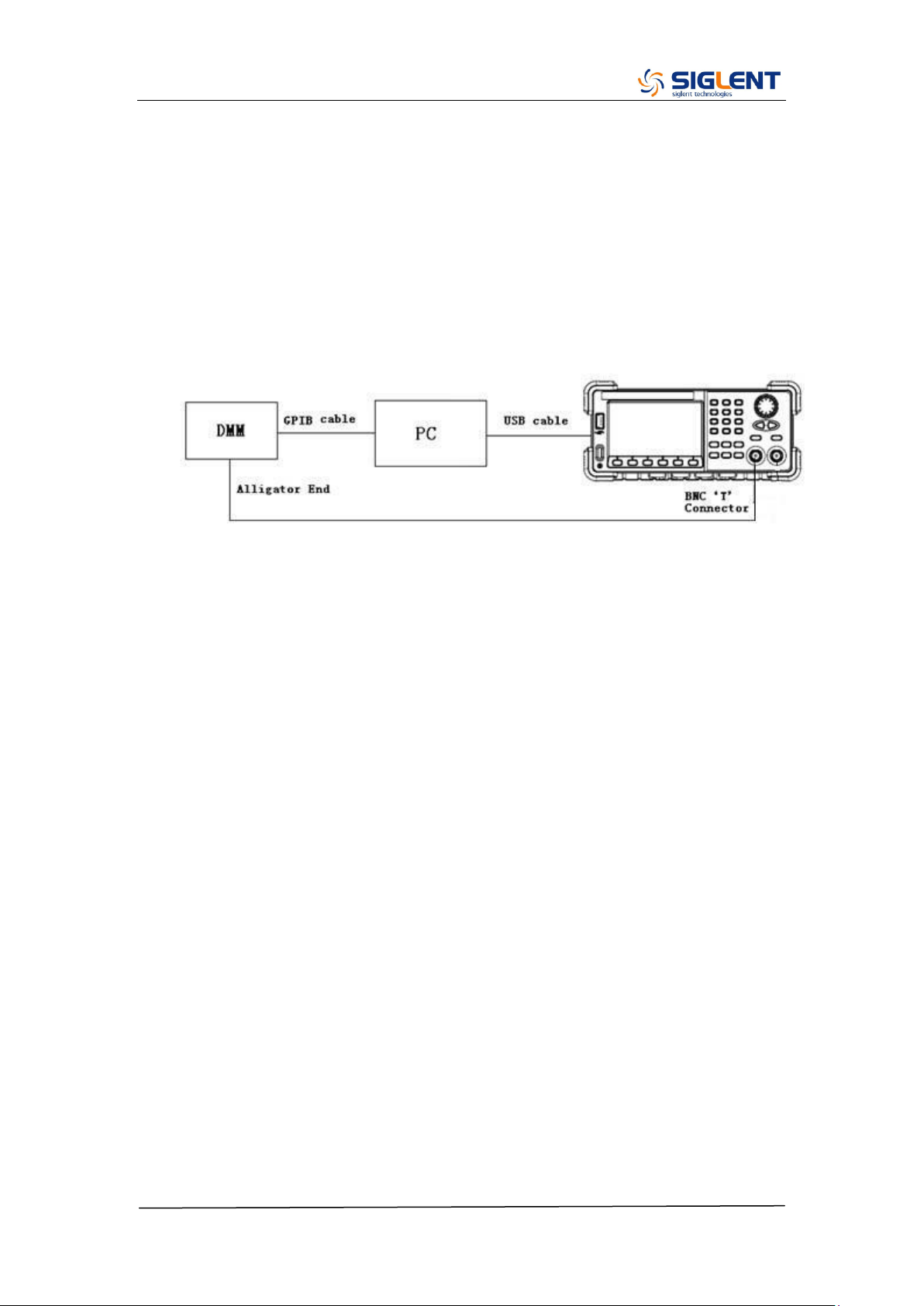
AC Amplitude Verification
This test checks the ac amplitude output accuracy at the frequency of 10 kHz
using a DMM.
1. Turn on the generator and choose CH1 as the operating channel. Set the
Load to 50 Ω.
2. Connect the DMM and generator as shown below.
3. Select Sine waveform of the generator and set the amplitude to the values
listed below in sequence.
Amplitude (V)
CH1 (V)
CH2 (V)
Spec Range (V)
± (1%+1 mV)
11
10.889~11.111
5.6
5.543~5.657
2
1.979~2.021
0.9
0.89~0.91
0.4
0.395~0.405
0.142
0.13958~0.14442
0.064
0.06236~0.06564
0.022
0.02078~0.02322
0.01
0.0089~0.0111
0.004
0.00296~0.00504
4. Remove the BNC cable to CH2 output and perform the same verification as
CH1.
5. Compare the value measured from the DMM to the spec range shown in the
table above.
SDG2000X Service Manual.doc
48
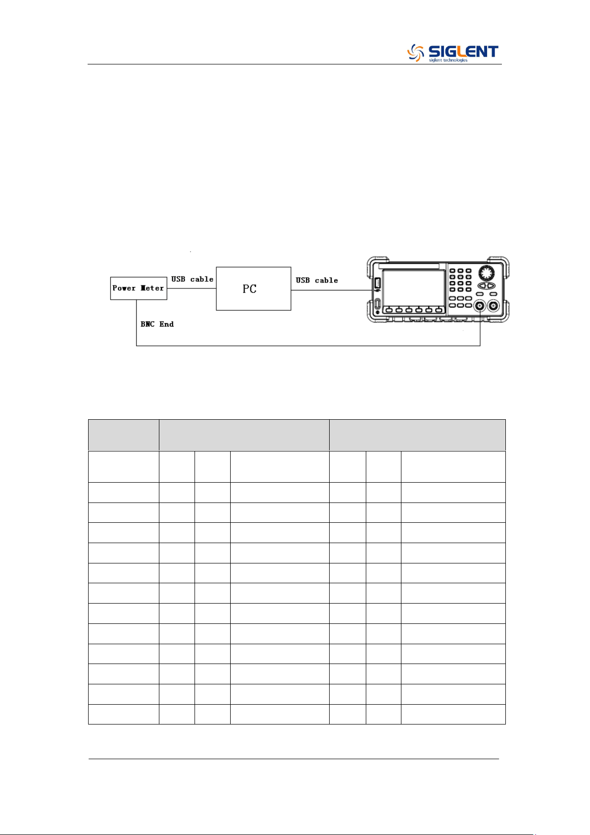
Frequency Response Verification
This test checks if the amplitude flatness is within the spec range using a
Power Meter.
1. Turn on the generator and choose CH1 as the operating channel. Set the
Load to 50 Ω.
2. Connect the Power Meter, PC and generator as shown below.
3. Select Sine waveform of the generator and set the amplitude to 1 V and 2.5
V, frequency to the values listed below in sequence.
Output
Voltage
1 V
2.5 V
Frequency
CH1
CH2
Spec Range
(dBm)
CH1
CH2
Spec Range
(dBm)
10 KHz
3.6794 ~ 4.2794
11.64 ~12.24
100 KHz
3.6794 ~ 4.2794
11.64 ~12.24
1 MHz
3.6794 ~ 4.2794
11.64 ~12.24
5 MHz
3.6794 ~ 4.2794
11.64 ~12.24
10 MHz
3.6794 ~ 4.2794
11.64 ~12.24
20 MHz
3.6794 ~ 4.2794
11.64 ~12.24
30 MHz
3.6794 ~ 4.2794
11.64 ~12.24
50 MHz
3.6794 ~ 4.2794
11.64 ~12.24
80 MHz
3.6794 ~ 4.2794
11.64 ~12.24
100 MHz
3.6794 ~ 4.2794
11.64 ~12.24
110 MHz
3.5794 ~ 4.3794
11.54 ~12.34
120 MHz
3.5794 ~ 4.3794
11.54 ~12.34
4. Remove the BNC cable to CH2 output and perform the same verification as

SDG2000X Service Manual.doc
49
CH1.
5. Compare the value measured from Power Meter to the spec range shown in
the table above.

SDG2000X Service Manual.doc
50
General Adjustment Procedure
The following explains how to adjust the SDG2000X series generator for
optimum operating performance.
Channel Adjustment which includes four steps: feedback channel
adjustment, channel self adjustment, vertical accuracy calibration and
frequency counter calibration.
Feedback Channel Adjustment which acts as a standard calibration
module, providing the accuracy assurance for Self Adjust.
Channel Self Adjustment which includes internal control channel
adjustment and signal channel adjustment.
Vertical Accuracy Calibration which calibrates the amplitude at low
frequency.
Frequency Counter Calibration which calibrates the trigger level of the
counter.
Frequency Response Adjustment which could properly compensate the
amplitude as the frequency increases.
TimeBase Calibration which calibrates the output frequency accuracy.

SDG2000X Service Manual.doc
51
Software Environment
1. Python
Make sure you have installed Python 2.7 in your computer. The following
modules of Python are required as well: PyVisa, PyQt4 and PyWin32.
2. Microsoft Office
As test reports are saved as „.xls‟, it is necessary that you are working with MS
Office 2003 or higher version.
3. NI VISA
The Python module, PyVisa, is based on VISA I/O library which can be derived
from NI VISA.
Warming up
Before performing the adjustment procedures, let the generator and other test
equipment warm up for at least 30 minutes in an ambient temperature between
18 °C and 28 °C. Adjustments performed prior to warm-up or outside this
temperature range may result in poor performance.
SDG2000X Service Manual.doc
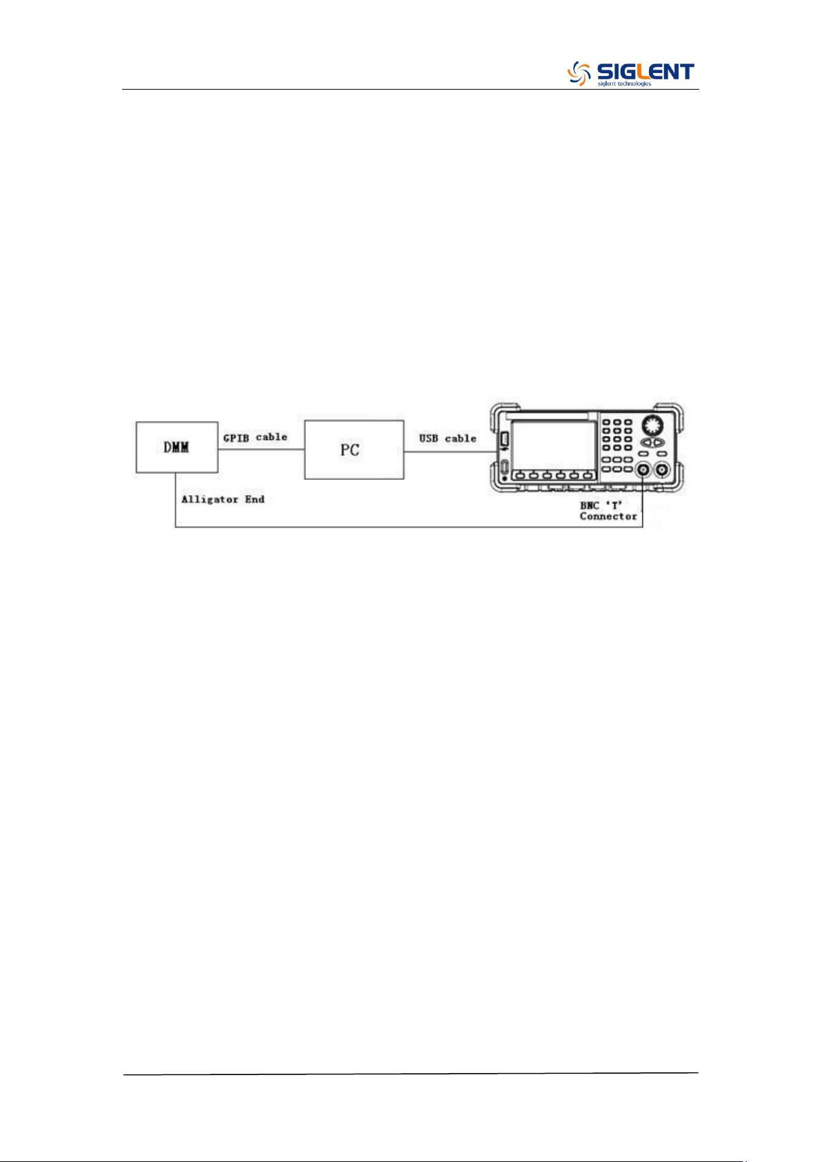
52
Channel Adjustment
The channel adjustment includes four parts: feedback channel adjustment,
channel self adjustment, vertical accuracy calibration and frequency counter
calibration.
1. Turn on the generator.
2. Connect the DMM, PC and SDG2000X generator as shown below:
3. Double click and run the script ChannelAdjust.py prepared previously.
Then Change the channel connection according to the prompt message.
Note:
If there is a problem in the process of the channel adjustment, you can
separately perform the four parts mentioned above. After the feedback channel
adjustment has been completed, perform a self adjustment. Then perform the
vertical accuracy calibration and frequency counter calibration in turn.
SDG2000X Service Manual.doc
53
Feedback Channel Adjustment
The internal feedback channel receives the feedback signal from all the other
channels that are performing self adjustment. This adjustment acts as a
standard test module and must be performed prior to Self Adjust to make sure
it is performed based on the best adjusting accuracy.
1. Connect the DMM, PC and SDG2000X generator as shown below:
2. Double click and run the script FeedbackAdjust.py prepared previously.
The CH1 will be automatically turned on upon running of the script.

SDG2000X Service Manual.doc
54
Channel Self Adjustment
This adjustment is for internal control channel and signal channel. Through
feedback circuits of the feedback channel and signal channel, this adjustment
helps to obtain the actual working performance for components from signal
channels.
1. After the feedback channel adjustment completed, disconnect the two
BNC cables on CH1 and CH2.
2. Input the password “123654” under the system info interface to show the
SelfCal menu and perform the self adjustment.
3. Once the “Self Adjust” begins, the generator turns to adjustment interface
and the progress bar displays on the screen. In about 20 seconds it will
reach 100%, which indicates completing of the self-adjust. The progress
bar will disappear automatically after 2 seconds.
SDG2000X Service Manual.doc
55
Vertical Accuracy Calibration
This adjustment aims to calibrate the amplitude at low frequency, using a DMM
with high precision. The SDG2000X begins this portion of the calibration after
the completion of the self adjustment. It calibrates the Sine wave with a 10 kHz
frequency and selects several amplitudes to calibrate. Compare the measured
amplitude and the standard to obtain a set of compensation values.
1. Connect the DMM, PC and SDG2000X generator as shown below:
2. Double click and run the script VertAccCalib.py prepared previously.
3. Change the channel connection according to the prompt message.
SDG2000X Service Manual.doc
56
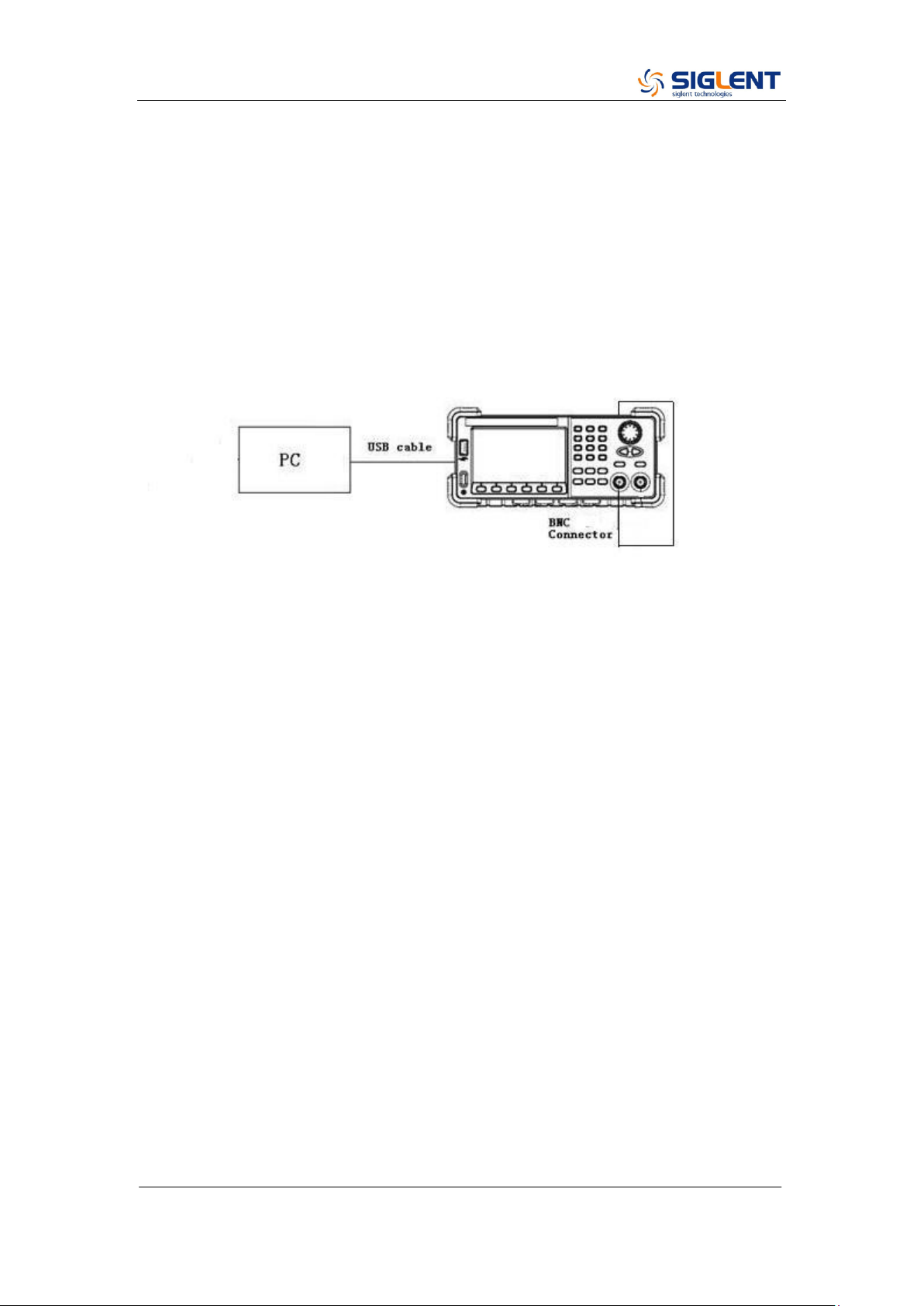
Frequency Counter Calibration
This adjustment aims to calibrate the trigger level of the counter to obtain more
accurate measured values.
1. Connect the PC and SDG2000X generator with a USB cable and connect
the CH1 at the front panel to the counter port at the rear panel with a BNC
cable, as shown below:
2. Double click and run the script FreqCounterCal.py prepared previously.
SDG2000X Service Manual.doc
57
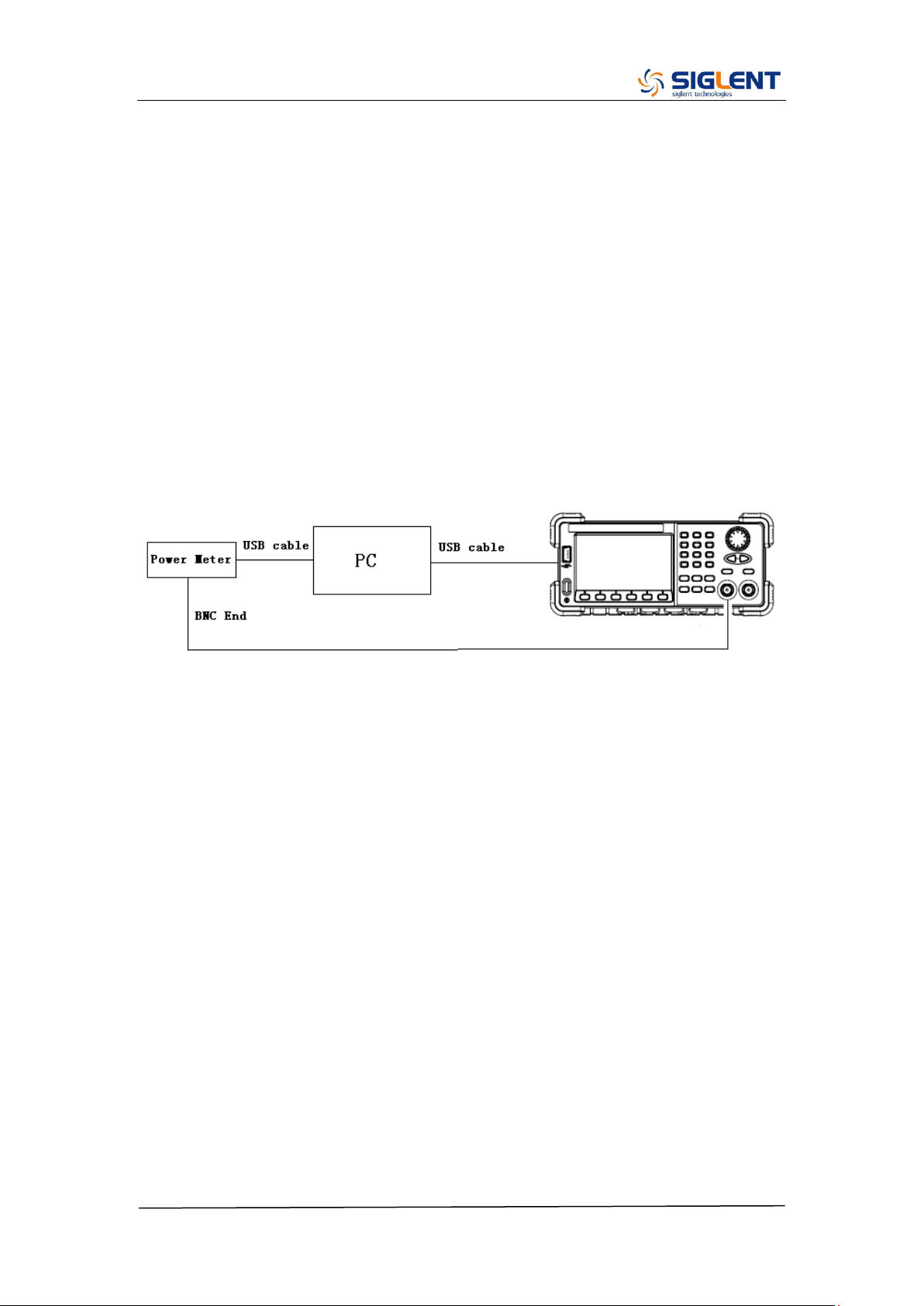
Frequency Response Adjustment
This adjustment aims to obtain the actual frequency response characteristics
of the signal channel, thus to perform appropriate compensation. Since the
waveform amplitude will decrease as the input frequency increases, it is
essential to compensate for the amplitude to match it to the frequency. This
adjustment should be performed after the channel adjustment.
1. Turn on the generator and connect it to the PC using a USB cable.
2. Connecting the USB end of the Power Meter to the USB port of the PC,
upon which the Power Meter indicator light will be brightened. Only after the
indicator light goes out from red, should it be connected to the generator
output.
3. Run the script FrqRespCalib.py prepared previously. In approximately 10
seconds the prompt message will display on the screen to indicate the
operator to connect the Power Meter. After the generator completes the
adjustment for CH1, the prompt message displays on the screen will
prompt the operator to remove the BNC cable to CH2 to start adjustment.
4. After the two channel adjustment completed, please disconnect all the
connections.
SDG2000X Service Manual.doc
58
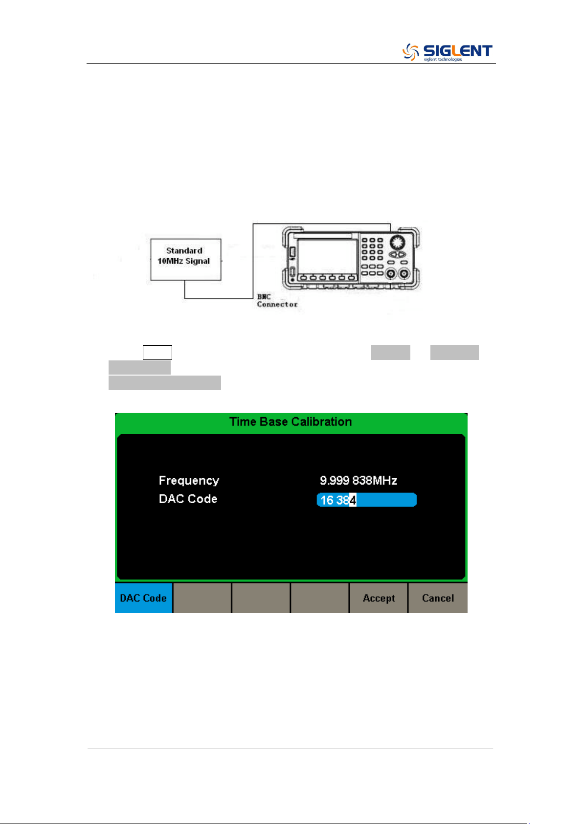
TimeBase Calibration
This adjustment aims to calibrate the output frequency accuracy through
adjusting the DAC code.
1. Connect the counter port at the SDG2000X‟s rear panel to a high accuracy
10 MHz signal with a BNC cable, as shown below:
2. Press Utility button on the front panel and select System → Page 1/2 →
System Info. Use the number keyboard to input “123654”. Then select the
TimeBase Calibration softkey. The timebase calibration interface is shown
as the following.
3. Use the numeric keyboard or knob to adjust the DAC code to make the
measured frequency to be closer to 10 MHz.

SDG2000X Service Manual.doc
59
Chapter 4 Assembly Procedures
This chapter describes how to remove the major modules from the SDG2000X
series generator. To install the removed modules or replace new modules,
please follow corresponding operating steps in reverse order.
The following subjects are addressed in this chapter:
Security Consideration which describes security information needed to
considerate while operating.
List of Module in which the modules to remove are listed.
Required Tool which describes the tools needed to perform the
procedures
Disassembly Procedures which describes in detail how to remove and
install the modules
Security Consideration
Only qualified personnel should perform the disassembly procedures.
Whenever possible, disconnect the power before removing or replacing.
Otherwise, personal injuries or damages to the components may occur.
Avoid Electric Shock Hazardous voltages exist on the LCD module and
power supply module. To avoid electrical shock, disconnect the power cord
from the generator, and then wait at least three minutes for the capacitors in
the generator to discharge before beginning the disassembly.
Preventing ESD Almost all electrical components can be damaged by
electrostatic discharge (ESD) during handling. Component damages can occur
at electrostatic discharge voltages as low as 50 volts. The following guidelines
will help preventing ESD damage when servicing the instrument or any
electronic device.
Disassemble instruments only in a static-free work area.
Use a conductive work area to reduce static charges.
Use a conductive wrist strap to reduce static charge accumulation.
Minimize handling.
Keep replacement parts in original static-free packaging.
SDG2000X Service Manual.doc
60
Remove all plastic, foam, vinyl, paper and other static-generating materials
from the immediate work area.
Use only anti-static solder suckers.
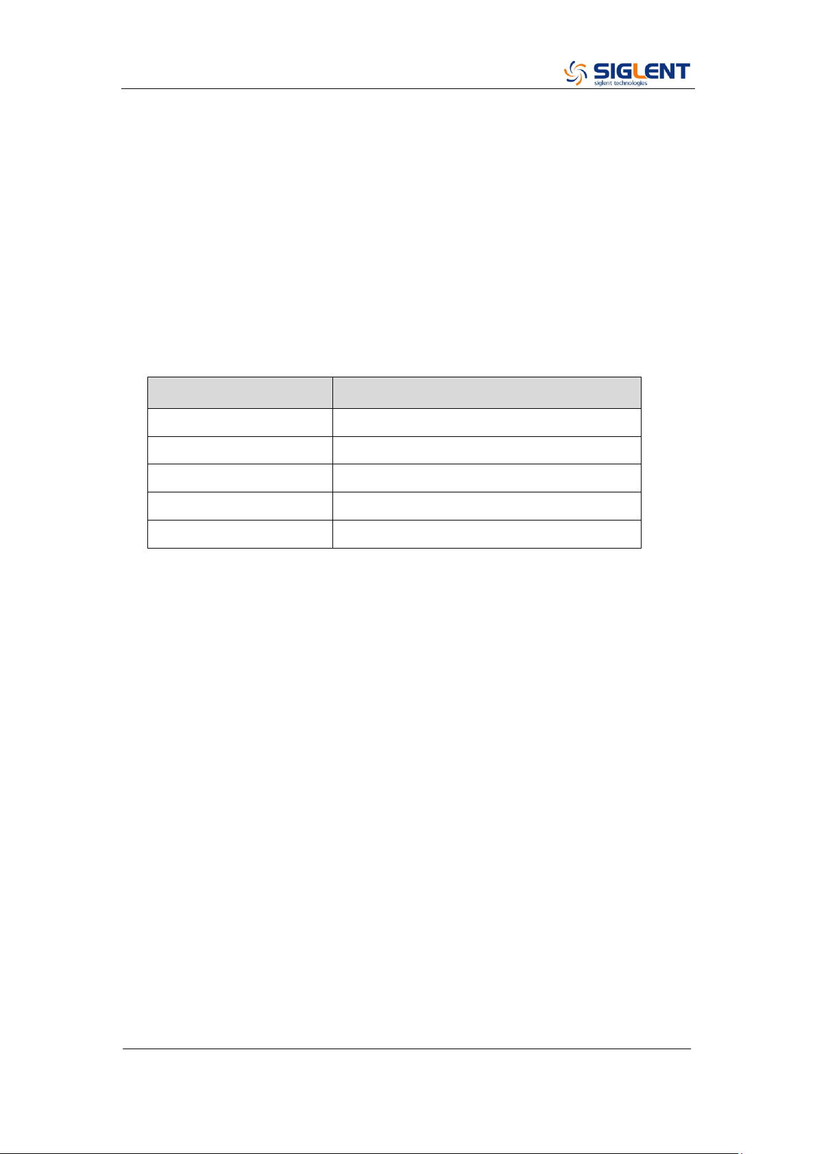
List of Modules
The following removable modules are listed in the order of performing
disassembly procedures.
Number of Module
Module
1
Handle
2
Metal Shell and Rear Cabinet
3
Front Cabinet
4
Display Module
5
Main Body
Required Tools
Use these tools to remove or replace the modules in the generator:
T10 and T15 Torx screwdriver

SDG2000X Service Manual.doc
61
Disassembly Procedures
This section describes how to remove and install the generator‟s modules
listed above in detail. Complete disassembly will be best achieved through the
following operating steps.
1. Pull out the handle hard from the two sides of the generator.
2. After removing 4PCS screws of the pad and 1PCS screw at the bottom of
the generator‟s case, remove the metal shell carefully from the main body
to avoid being scratched.
SDG2000X Service Manual.doc
62
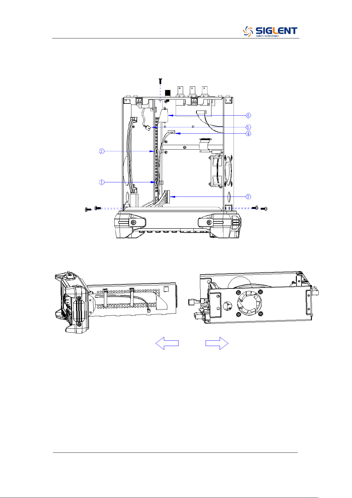
3. Open the cable clamp as ①② show and pull out the cable as ③④⑤⑥
show, and then remove the 5PCS screws as shown in the following figure.
4. Separate the front panel from the main body of the generator.
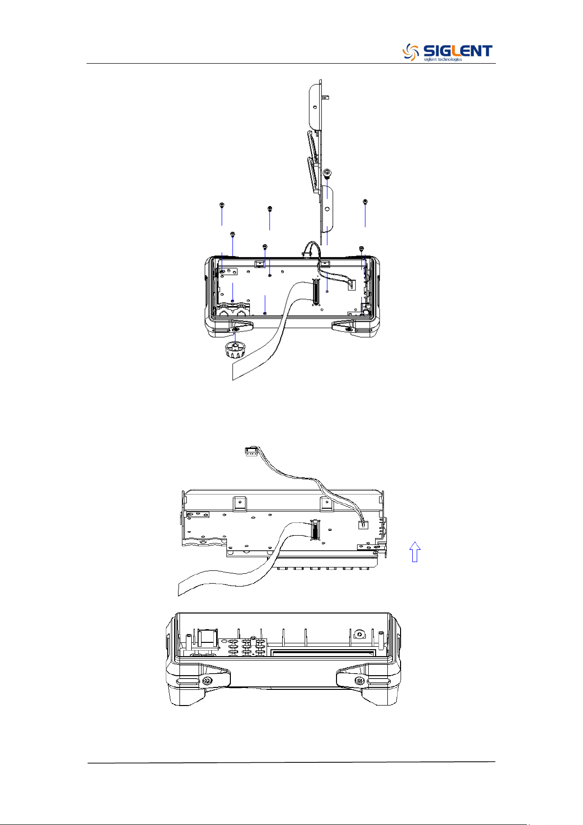
5. Pull out the knob and then remove the screws attaching the hardware
partition plate and the front cabinet screws.
SDG2000X Service Manual.doc
63
6. Remove the keypad circuit board assembly.
7. Remove the 3PCS screws holding the screen bracket and remove the
SDG2000X Service Manual.doc
64
metal front panel.
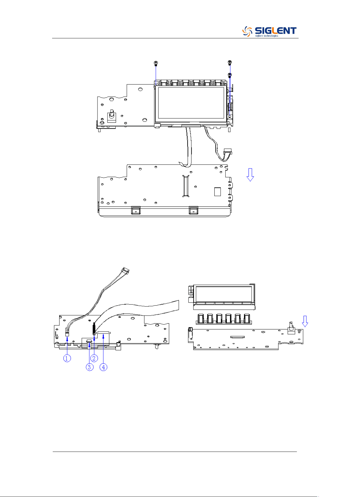
8. Pull out the connecting cable according to the index number as shown in
the following figure and remove the keyboard.
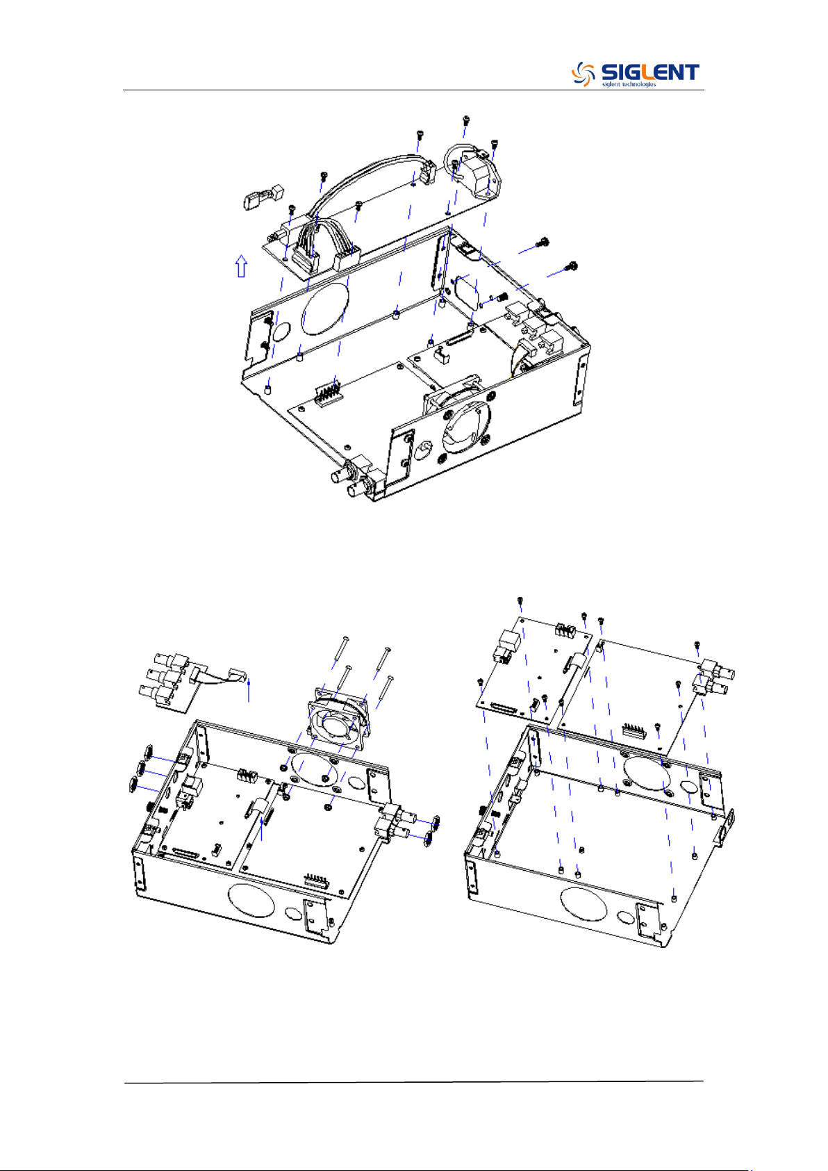
9. Remove all the 9 screws fixed the main board and power supply board
using the T10 Torx screwdriver and separate the main board and power
supply board carefully from the main body of the generator to avoid being
scratched by the sharp metal edge.
SDG2000X Service Manual.doc
65
10. Pull out the connecting cable as shown in the following figure and then
remove the fan, rear interface board, channel board and main board.
Note:
To assemble the generator, please follow these same steps in reverse order.

SDG2000X Service Manual.doc
66
Chapter 5 Troubleshooting
The internal structure of the generator consists of the main board, channel
board, power supply board, key and LCD board, and interface board. They are
linked through cables or connectors. This chapter explains the main
troubleshooting procedures for these boards (mainly main board and channel
board) by measuring the corresponding test points and checking the signals of
connectors on them, thus to help in determining the reason for the failure that
has been encountered while operating the SDG2000X series arbitrary
waveform generator.
ESD Precautions
While performing any internal test of the generator, please refer to the following
precautions to avoid damages to its internal modules or components resulting
from ESD.
Handle circuit boards by their edges as much as possible.
Avoid handling of static-sensitive modules if not necessary. .
Wear a grounded antistatic wrist strap to drain the static voltage from your
body while touching these modules.
Operate static-sensitive modules only in static-free areas. Avoid handling
modules in areas that allow anything capable of generating or holding a
static charge.
Required Equipments
The equipment listed in the table below is required to troubleshoot the
generator.
Table 5-1 Required Equipments
Equipment
Critical Specifications
Example
Digital Multimeter
DC Accuracy ±0.015%
SDM3055

SDG2000X Service Manual.doc
67
Oscilloscope
300 MHz Bandwidth
SDS2304X
SDG2000X Service Manual.doc
68
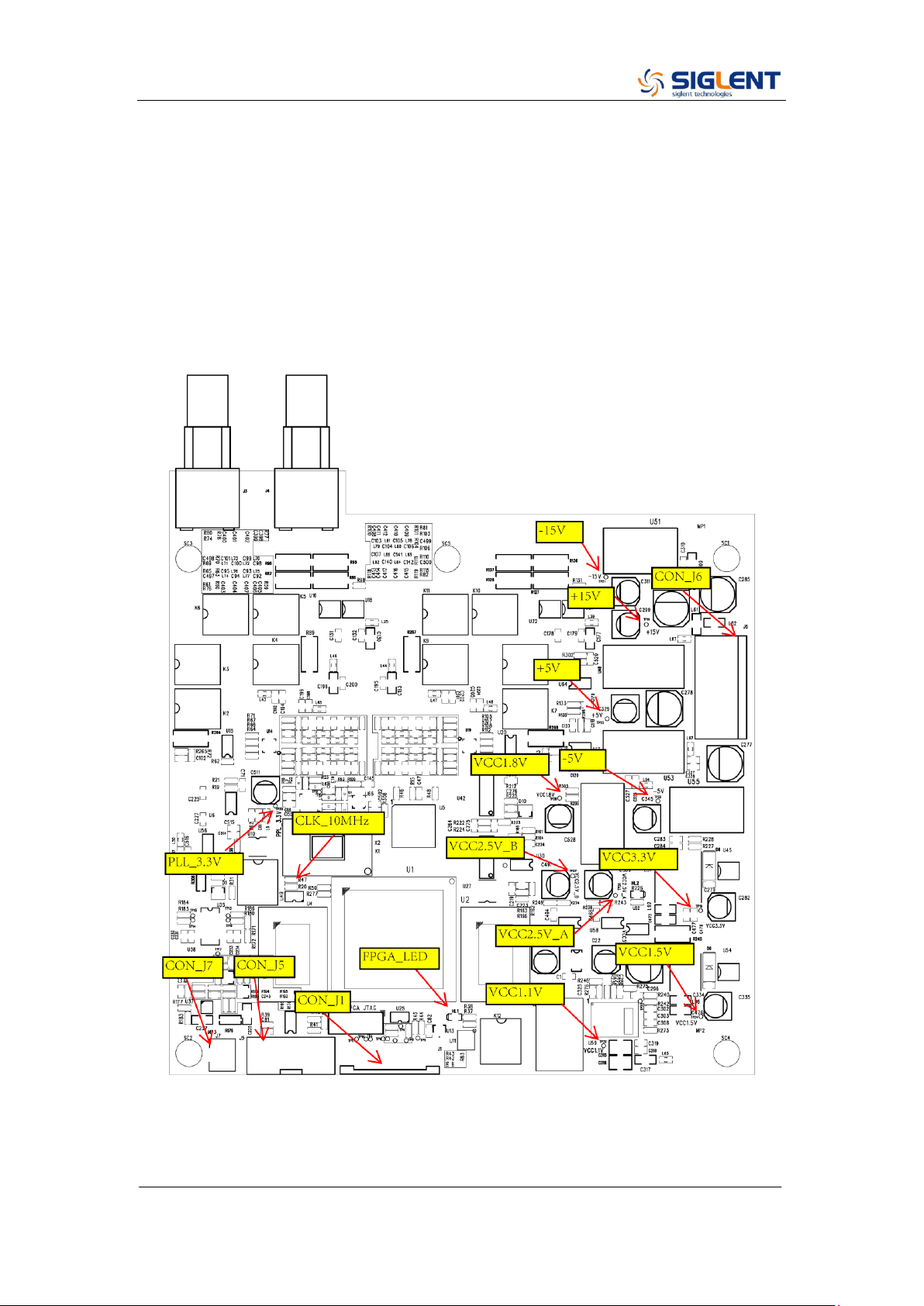
Channel Board Drawing
The channel board is a kind of signal conditioning board for generating analog
signal. It mainly deals with the adjusting of signal parameters such as
frequency, amplitude, and so on. Please refer to the following drawing to
quickly locate the test points on the channel board for easy resolution of any
problems encountered.
SDG2000X Service Manual.doc
69
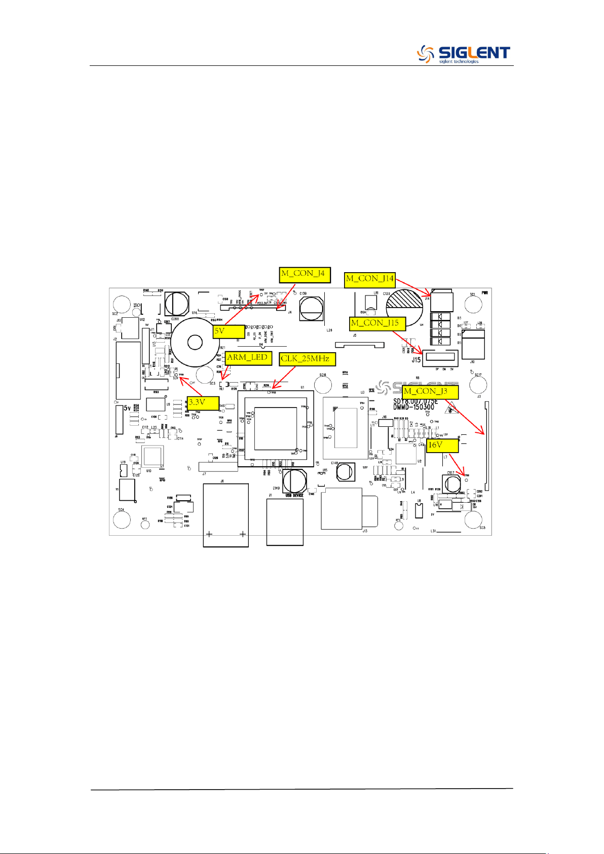
Main Board Drawing
The main board is the control center of the generator that contains an ARM
CPU system. It completes the GUI function, controlling and configuration
function of the channel board as well as the user interface. Please refer to the
following drawing to quickly locate the test points on the main board for easy
resolution of any problems encountered.
SDG2000X Service Manual.doc
70
Check the Power Supply
There are two power connectors through which the channel board and main
board can be supplied power.
Before performing the power supply testing procedure, please make sure that
the generator is grounded correctly through the protective lead of the power
cord. Take care not to touch or even disassemble the power supply module
without any safety precautions, electric shock could occur. Here are
procedures for testing the power supply:
1. Disconnect the power cord of the generator and then check whether the
fuse is good.
2. Remove metal shell of the generator, and then disconnect the power
connector connected to the main board.
3. Focus on the Power Connector for channel board, which contains 6 pins
from Pin 1 to Pin 6. Since two of the six pins are ground wire, test the other
four pins that are marked with blue, yellow, red and white to check whether
the voltage value is within the corresponding specified range using a digital
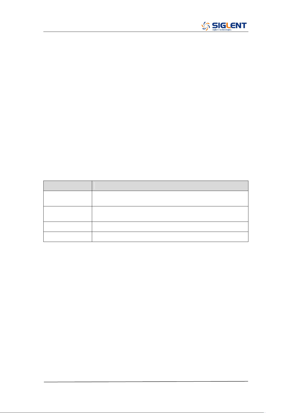
multimeter. The voltage parameters to be tested are listed in the table below:
Table 5-2 Test Voltages of Power Connector
Voltage value
Pins
Error limit
20 V
VH+(red)
±10%
-20 V
VH-(white)
±10%
6.5 V
VL+(yellow)
±10%
-6.5 V
VL-(blue)
±10%
If each tested voltage value is within the corresponding specified range listed
in the table above, then the power supply is working normally. Otherwise,
please go to step 4.
4. Disconnect the power connector and redo step 3. Because of the removal of
the load, each voltage value error limit increases by approximately 20
percent.
Table 5-3 Test Voltages of the Connector After Disconnected
Voltage value
Pins
Error limit
20 V
VH+(red)
±30%

SDG2000X Service Manual.doc
71
-20 V
VH-(white)
±30%
6.5 V
VL+(yellow)
±30%
-6.5 V
VL-(blue)
±30%
If each tested voltage value is within the specified range listed in the table
above, then some abnormality of the load is most likely causing the power
supply problem. Continuous checking or even replacing the channel/main
board is required for further test.
If there is at least one voltage value that is out of the specified range, then the
power supply module appears to be problematic, and a replacement will be
required. For safety, please have qualified technical personnel to disassemble
the power supply module.
Note: The main power supply provides an input fuse to protect against the
danger of fire in the event of a failure of the power supply circuitry. However,
this fuse will not fail ("open" or "blow") in normal power supply operation except
when a significant overload occurs. Replace the entire main power supply
assembly if the input fuse fails.
SDG2000X Service Manual.doc
72
Check the Channel Board
If it is desired to remove the channel board from the metal shelf inside the
generator, please place it on a clean, insulated mat. Here are the procedures
for testing the main board:
1. Several types of connectors are used on the channel board. Check to
make certain that all of these are connected properly.
2. After checking these connectors, then connect the generator to AC power
and power it on. Check if the voltage values at all test points are within the
specified range using a digital multimeter. The voltage parameters to be
tested are listed in table 5-4:
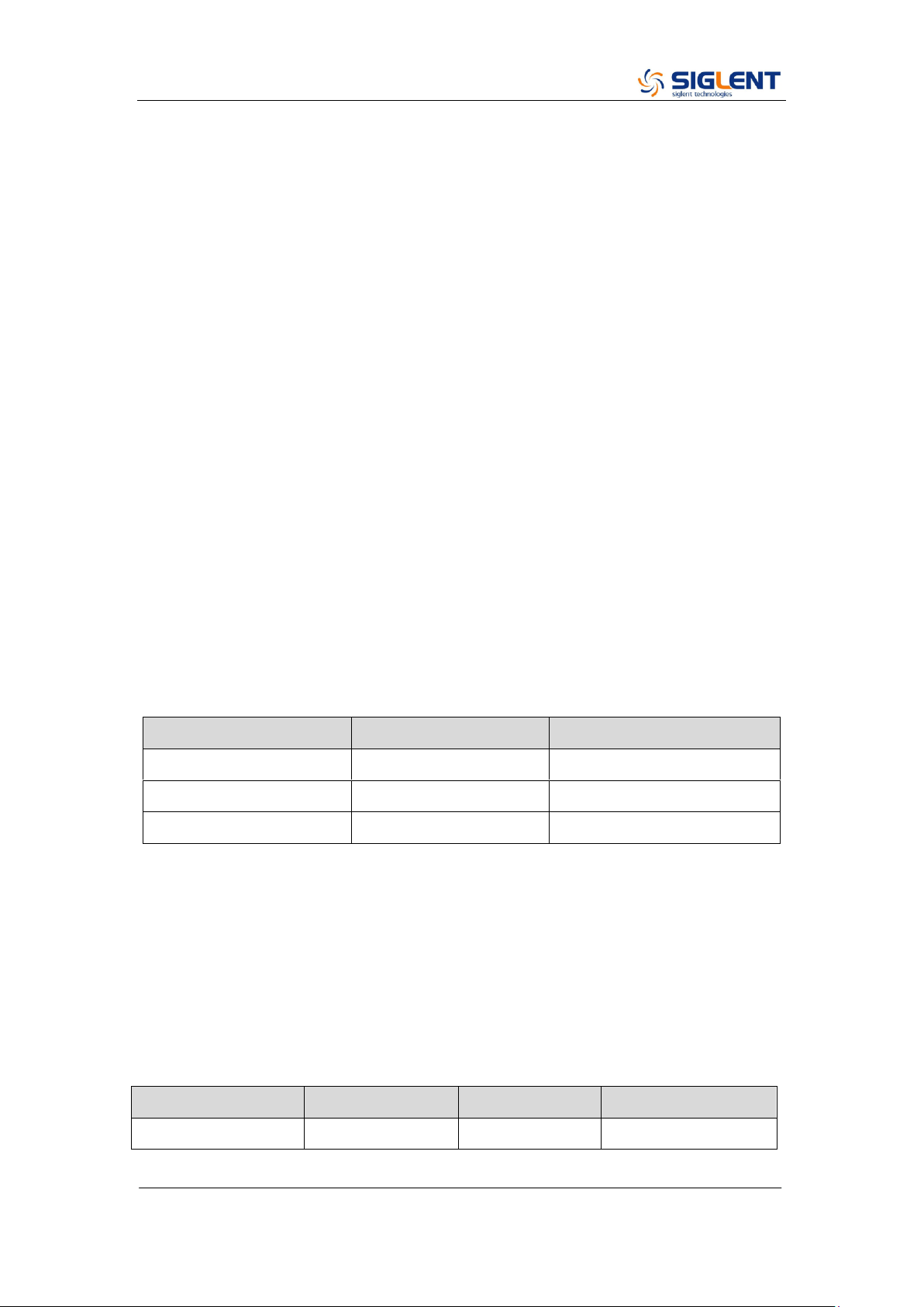
Voltage Checking
Test the voltage points on the channel board in the table below. To locate the
test points, please refer to the drawing of the channel board. If not each tested
voltage value is within the corresponding spec range referring to table 5-4, it
proves to be faulted, please return it to the factory to have it repaired or contact
SIGLENT.
Table 5-4 Test Voltages of the Channel Board
Test point
Voltage value
Error limit
+15 V
+15 V
±5%
-15 V
-15 V
±5%
-5 V
-5 V
±5%
+5 V
+5 V
±5%
VCC1.8 V
+1.8 V
±5%
VCC3.3 V
+3.3 V
±5%
VCC2.5 V_A
+2.5 V
±5%
VCC2.5 V_B
+2.5 V
±5%
VCC1.5 V
+1.5 V
±5%
VCC1.1 V
+1.1 V
±5%
PLL_3.3 V
+3.3 V
±5%
SDG2000X Service Manual.doc
73
10 MHz Clock Source Checking
There is a TXCO generating a 10 MHz 3.3 V LVCOMS clock source to the
entire channel board. Please check it, referring to the marked point on the
channel board drawing.
FPGA Checking
To check if the FPGA is working properly, please observe the test point marked
with FPGA_LED on the channel board drawing. The LED light flashes at the
rate of 1Hz in normal case, if it cannot be lighted or twinkles at incorrect
frequency, then the FPGA may be at fault.
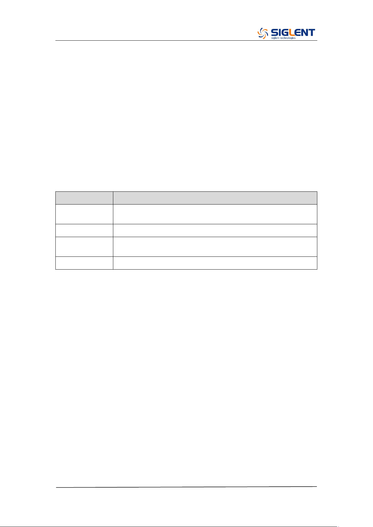
Connector Checking
Table 5-5 Connectors of the Channel Board
Connector
Function
CON_J1
Communication between the main board and the
channel board.
CON_J5
Communication between the channel board and the
interface board.
CON_J6
Power supply of the channel board.
CON_J7
Power supply of the fan.
Table 5-5 explains the function of all the connectors on the channel board. It is
important to ensure that all the connections are tight.
SDG2000X Service Manual.doc
74
Check the Main Board
If the power board does need to be removed from the metal shelf located
inside the generator, place it on a clean, insulated mat. Testing procedures for
the main board are as follows:
1. Several types of connectors are located on the main board. Check if all
these are connected properly.
2. Make certain that the connectors on the main board are properly connected,
then connect the generator to AC power and turn it on. Check if the voltage
values at all test points are within the spec range using a digital multimeter.
The voltage parameters to be tested are listed in table 5-6:
Voltage Checking
Test the voltage points on the main board and compare to the table below. If
each tested voltage value is within the corresponding specified range referring
to the table below, then the main board works normally. If the voltages are out
of the specified range, please return it to the factory to have it repaired or
contact SIGLENT.
Table 5-6 Test Voltages of the Main Board
Test point
Voltage value
Error limit
16 V
16 V
±5%
3.3 V
3.3 V
±5%
5 V
5 V
±5%
Main Board Clock Checking
The main board clock is the internal system clock of the generator. To verify if
the clock on the main board is working normally, please test the clock using an
oscilloscope.
Table 5-7 Clock Source of the Main Board
Test point
Frequency
Stability
Level
CLK_25 MHz
25 MHz
±50 ppm
3.3 V LVCOMS
SDG2000X Service Manual.doc
75
ARM CPU System Checking
Observe the ARM_LED light on the main board, which indicates the working
state of ARM CPU system. If the light turns on, then the corresponding codes
have been loaded successfully and the chip is in an operating state. Otherwise,
there may be a problem with it.
Connector Checking
Table 5-8 Connectors of the Main Board
Connector
Function
M_CON_J3
Communication between the main board and the Key and
LCD board.
M_CON_J14
Power supply of the main board.
M_CON_J4
Communication between the main board and the channel
board.
M_CON_J15
USB host connector.
Table 5-8 explains the function of all the connectors on main board. It is
important to ensure that all the connections are tight.

SDG2000X Service Manual.doc
76
Quick Guide for General Failures
The general hardware failures are described in the following. Reading the
following information can help in determining the cause of some general
hardware failures:
1. No start-up after pressing the power button:
(1) Check if the power cord is correctly connected.
(2) Check if the power button is operating correctly..
(3) Check whether the fuse has been burned out. If the fuse is blown, please
replace with a fuse of the same rating
(4) Check if the the connection between the power supply and the main board.
(5) If the instrument still does not work normally, please contact SIGLENT.
2. Starts up with a dark screen:
(1) Check the connection between the power supply and the main board.
(2) Check the connection between the keypad circuit board and the main
board.
(3) If the instrument still does not work normally, please contact SIGLENT.
3. No response after pressing any button, or abnormal display of the
screen:
(1) Check the connection between the keypad circuit board and the main
board.
(2) If the instrument still does not work normally, please contact SIGLENT.
4. The output voltage amplitude measured is higher or lower than
expected:
(1) Check the connection between the generator and the load.
(2) Check if the impedance set in generator matches the input impedance of
the load.
(3) If the instrument still does not work normally, please contact SIGLENT.

SDG2000X Service Manual.doc
77
Chapter 6 Maintenance
Maintain Summary
SIGLENT warrants that the products it manufactures and sells are free from
defects in materials and workmanship for a period of three years from the date
of shipment from an authorized SIGLENT distributor. If a product proves
defective within the respective period, SIGLENT will provide repair or
replacement as described in the complete warranty statement.
To arrange for service or obtain a copy of the complete warranty statement,
please contact your nearest SIGLENT sales and service office.
Except that as provided in this summary or the applicable warranty Statement,
SIGLENT makes no warranty of any kind, express or implied, including without
limitation the implied warranties of merchantability and fitness for a particular
purpose. In no case shall SIGLENT be liable for indirect, special or
consequential damages.
Repackaging for Shipment
If the unit needs to be shipped to SIGLENT for service or repair, be sure:
1. Attach a tag to the unit identifying the owner and indicating the required
service or repair.
2. Place the unit in its original container with appropriate packaging material
for shipping.
3. Secure the container with strong tape or metal bands.
If the original shipping container is not available, place your unit in a container
which will ensure at least 4 inches of compressible packaging material around
all sides for the instrument. Use static-free packaging materials to avoid
additional damage to your unit.

SDG2000X Service Manual.doc
78
Contact SIGLENT
SIGLENT TECHNOLOGIES CO., LTD
Address: 3/F, NO.4 building, Antongda Industrial Zone, 3rd Liuxian Road, 68th
District, Baoan District, Shenzhen, P.R. China
Tel: 400-878-0807
E-mail: [email protected]
http: //www.siglent.com
In North America: http://www.siglentamerica.com