X + 0 + Y
2
0 M
H Z
D E S I G N G O A L :
Bring the thrill of live performanc e and movie sound to
the home environment by calling on J BL’s professional engineering leadership.
S A T E L L I T E T Y P E :
Titanium-laminate-dome tw eeter, sealed enclosure
S U B W O O F E R T Y P E :
Bass-reflex enc losure
P O R T D E S I G N :
FreeFlow ™ flared
P R O F E S S I O N A L R E F E R E N C E :
Cinema Loudspeaker Series
O W N E R ’ S G U I D E
P R O D U C T L I N E :
M O D E L
S C S 135
N U M B E R :
X +
0 +
Y
2
0
M
H Z
4 ”
8 ”
X +
0 +
Y
2
0
M
H Z
J B L Consumer P roducts
250 Crossw ays P ark Drive, W oodbury, N Y 11797
8500 B alboa B oulevard, N orthridge, CA 91329
800-336-4J B L (4525) (USA only)
w w w.jbl.com
©2000 J BL, Inc orporated.
J B L is a registered trademark of J B L, Inc orporated.
Part No.
ai5073
D E S I G N G O A L :
Bring the thrill of live performanc e and movie sound to
the home environment by calling on J B L’s professional engineering leadership.
S A T E L L I T E T Y P E :
Titanium-laminate-dome tw eeter, sealed enclosure
S U B W O O F E R T Y P E :
Bass-reflex enc losure
P O R T D E S I G N :
FreeFlow ™ flared
P R O F E S S I O N A L R E F E R E N C E :
Cinema Loudspeaker Series
O W N E R ’ S G U I D E
P R O S O U N D
C O M E S H O M E
™
P R O D U C T L I N E :
M O D E L
S C S 135
N U M B E R :
S P E C I F I C A T I O N S
Refinements may be made on oc c asion to existing produc ts w ithout notice, but w ill alw ays meet
or exceed original specifications unless otherw ise stated.
Simply Cinema is a registered trademark of J BL, Inc orporated.
* Dolby and P ro Logic are trademarks of Dolby Laboratories.
DTS is a registered trademark of Digital Theater Systems, Inc.
®
®
SCS135 System
Frequenc y Response
35Hz – 20kHz (– 6dB )
Satellites
Recommended Pow er
10 –
100
w atts
Impedance
8 ohms nominal
Sensitivity
86dB @ 1 w att/1 meter
Tw eeter
One 1/2"titanium-laminate
dome, video-shielded
M idrange
One 3" driver, video-shielded
Dimensions (H x W x D)
4-3/8" x 3-3/16" x 3-3/4"
111mm x 81mm x 95mm
W eight
1.1 lb/0.5kg
Center
Recommended Pow er
10 – 50 w atts
Impedance
8 ohms nominal
Sensitivity
86dB @ 1 w att/1 meter
Tw eeter
One 1/2"titanium-laminate
dome, video-shielded
M idrange
Dual 3" drivers, video-shielded
Dimensions (H x W x D)
3-1/4" x 7-5/8" x 3-3/4"
83mm x 194mm x 95mm
W eight
1.89 lb/0.86kg
Subw oofer
Amplifier
100 w atts RM S
Bass
8" w oofer, bass-reflex
enc losure
Dimensions (H x W x D)
15" x 13" x 14"
381mm x 330mm x 356mm
W eight
30 lb/13.6kg
3
R E A D T H I S ! I m p o r t a n t S a f e t y P r e c a u t i o n s !
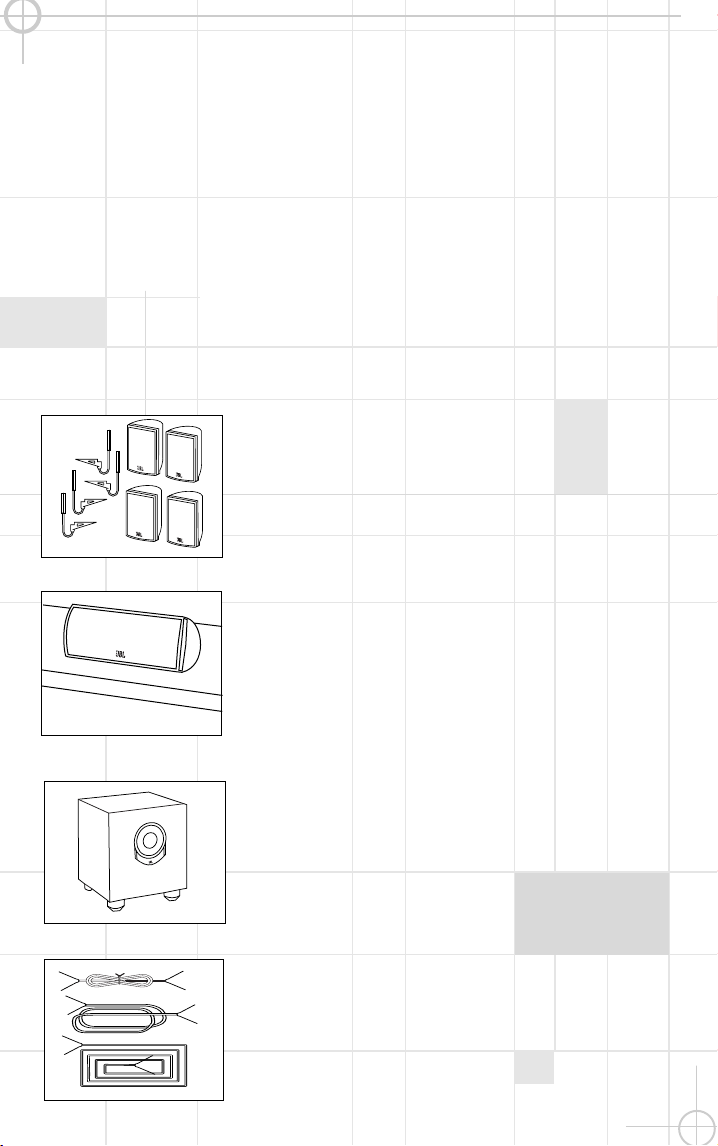
I N C L U D E D
Four satellites for left, right and
surrounds. W all-mount brac kets.
One center-c hannel speaker
w ith adjustable support leg.
P ow ered subw oofer.
2
1. Read I nstructions.
All the safet y and
operating i nstructions should be read before
the product i s operated.
2. Retain I nstructions.
The safety and
operating i nstructions should be retained
for future reference.
3. Heed Warnings.
All warnings on the
product and in t he operating i nstructions
should be adhered to.
4. Follow I nstructions.
All operati ng and
use i nst ructions should be followed.
5. Cleaning.
Unplug thi s product from the
wall out let before cleani ng. Do not use
li quid cleaners or aerosol cleaners. Use a
damp cloth for cleani ng.
6. Attachments.
Do not use attachments
not recommended by the product
manufacturer, as t hey may cause hazards.
7. Water and Moisture.
Do not use this
product near water – for example, near a
bathtub, wash bowl, kitchen si nk or laundry
tub; in a wet basement ; near a swimmi ng
pool; or t he li ke.
8. Accessories.
Do not place thi s product
on an unstable cart, st and, tripod, bracket
or table. The product may fall, causi ng
serious injury to a chi ld or adult , and
serious damage to the product . Use only
wi th a cart, stand, tri pod, bracket or table
recommended by the manufacturer, or sold
wi th the product . Any mounting of the
product should follow t he manufacturer’s
instructions, and should use a mounting
accessory recommended by the
manufacturer.
9. A Product and Cart
Combination Should Be
Moved with Care.
Quick
stops, excessive force
and uneven surfaces may
cause the product and
cart combi nation to overturn.
10. Ventilation.
Slots and openi ngs in the
cabi net are provided for venti lation and to
ensure reliable operation of t he product and
to protect i t from overheating, and these
openi ngs must not be blocked or covered.
The openi ngs should never be blocked by
placing the product on a bed, sofa, rug or
other simi lar surface. This product should
not be placed i n a built- in i nstallation,
such as a bookcase or rack, unless proper
ventilat ion i s provided or t he
manufacturer’s inst ruct ions have been
adhered to.
11. Power Sources.
This product should be
operated only from the type of power
source indicated on the marking label. I f
you are not sure of the type of power
supply t o your home, consult your product
dealer or local power company. For product s
intended t o operate from battery power, or
other sources, refer to the operati ng
instructions.
12. Grounding or Polarization.
This
product may be equipped with a polarized
alternating- current- line plug (a plug having
one blade wider than the other) . This plug
wi ll fi t into the power outlet only one way.
This i s a safet y feature. I f you are unable
to i nsert the plug fully int o the outlet, try
reversi ng the plug. I f the plug should st i ll
fail to fit, contact your electrician to
replace your obsolete outlet. Do not defeat
the safety purpose of t he polarized plug.
13. Power-Cord Protection.
Power-supply
cords should be rout ed so that they are not
li kely to be walked on or pi nched by items
placed upon or against them, paying
particular att ention to cords at plugs,
convenience receptacles, and the point
where they exit from the product.
14. Nonuse Periods.
The power cord of the
product should be unplugged from the
outlet when left unused for long periods of
ti me.
15. Outdoor Antenna Grounding.
I f an
outside antenna or cable syst em is
connect ed to the product, be sure the
antenna or cable system i s grounded so as
to provide some prot ection against voltage
surges and built - up stat ic charges. Article
810 of the National Electrical Code,
ANSI / NFPA 70, provides i nformation wi th
regard to proper grounding of the mast and
supporting structure, grounding of t he lead-
in wire to an antenna di scharge unit, size
of groundi ng conductors, location of
antenna- di scharge uni t, connection to
groundi ng electrodes, and requi rements for
the groundi ng electrode. See Figure A.
16. Lightning.
For added protection for
this product duri ng a lightni ng storm, or
when i t is left unat tended and unused for
long periods of time, unplug it from the
wall out let and di sconnect the antenna or
cable system. Thi s wi ll prevent damage to
the product due to light ning and power- line
surges.
17. Power Lines.
An outside antenna
system should not be located i n the vicini ty
of overhead power lines or other electric
light or power circui ts, or where it can fall
into such power lines or circui t s. When
installing an outside ant enna system,
extreme care should be taken to keep from
touching such power lines or circuits, as
contact with them might be fatal.
18. Overloading.
Do not overload wall
outlets, extension cords, or integral
convenience receptacles, as thi s can result
in a ri sk of fire or electric shock.
19. Object and Liquid Entry.
Never push
objects of any kind into t his product
through openi ngs, as t hey may touch
dangerous voltage points or short- out parts
that could result in a fire or electric shock.
Never spill liquid of any ki nd on t he
product.
20. Servicing.
Do not attempt to service
this product yourself, as opening or
removi ng covers may expose you t o
dangerous voltage or other hazards. Refer
all servici ng to qualified service personnel.
21. Damage Requiring Service.
Unplug
this product from the wall outlet and refer
servici ng to qualified service personnel
under the following condi tions:
a.
The power- supply cord or t he plug has
been damaged; or
b.
Object s have fallen onto, or liquid has
been spi lled i nto, the product; or
c.
The product has been exposed to rain or
wat er; or
d.
The product does not operate normally
when following the operating instructions.
Adj ust only t hose controls that are covered
by the operati ng instructions, as an
improper adj ustment of other controls may
result i n damage and will often requi re
extensi ve work by a qualified technician to
restore the product to i t s normal operation;
or
e.
The product has been dropped or
damaged in any way; or
f.
The product exhi bits a distinct change in
performance; t his i ndicat es a need for
service.
22. Replacement Parts.
When replacement
parts are requi red, be sure the service
technician has used replacement parts
speci fied by the manufacturer or that have
the same characteri st ics as the origi nal
part. Unauthorized substitutions may result
in fire, electric shock or other hazards.
23. Safety Check.
Upon completion of any
service or repai rs to this product, ask the
service technician t o perform safety checks
to determi ne that the product is i n proper
operating condition.
24. Wall or Ceiling Mounting.
The product
should be mounted to a wall or ceiling only
as recommended by the manufacturer.
25. Heat.
The product should be situated
away from heat sources such as radiators,
heat regi sters, stoves or other products
(includi ng amplifiers) that produce heat.
Antenna Lead-In Wire�
�
Ground Clamp�
�
Antenna Discharge Unit (NEC Section 810-20)�
�
Grounding Conductors (NEC Section 810-21)�
�
Electric Service Equipment�
�
Ground Clamps�
�
Power Service Grounding Electrode System�
(NEC Art 250, Part H)
CAUTION
RISK OF ELECTRIC SHOCK
DO NOT OPEN
CAUTION: To prevent electric shock,
do not remove the grounding plug
on the power cord, or use any plug
or extension cord that does not have
a grounding plug provided.
Make certain that the
AC outlet is properly grounded.
Do not use an adapter plug
with this product.
The lightning flash with arrowhead symbol,
within an equilateral triangle, is intended to
alert the user to the presence of uninsulated
“dangerous voltage” within the product’s
enclosure that may be of sufficient magnitude to constitute a
risk of electric shock to persons.
The exclamation point within an equilateral
triangle is intended to alert the user to the
presence of important operating and
maintenance (servicing) instructions in the
literature accompanying the appliance.
Fig u re A .
Example o f A n tenn a
Gr o u nding as p e r N atio na l
Elec tr ic al Co d e , A N S I /N FP A 70
Part N o. J B LULB 10/ 99
For more than 50 years, J B L
has been involved in every
aspec t of music and film
rec ording and reproduc tion,
from live performanc es to
the rec ordings you play in
your home, c ar or offic e.
W e’re c onfident that the
J B L system you have
chosen w ill provide
every note of enjoyment that
you expec ted – and that
w hen you think about
purchasing additional audio
equipment for your home,
car or offic e, you w ill onc e
again choose J B L.
P lease take a moment to
complete the enc losed
profile c ard. It enables
us to keep you posted
on our latest advanc e-
ments, and helps us to
better understand our
customers and build
produc ts that meet their
needs and expectations.
J B L Consumer P roducts
T H A N K Y O U F O R C H O O S I N G J B L
Tw o 20' speaker c ables for
connec tion from receiver to
subw oofer.
Tw o 15' speaker c ables for
connec tion from subw oofer to
front speakers.
Three 40' speaker c ables for
connec tion from receiver to
left and right rear satellites
and c enter speaker.
3
R E A D T H I S ! I m p o r t a n t S a f e t y P r e c a u t i o n s !
I N C L U D E D
Four satellites for left, right and
surrounds. W all-mount brac kets.
One center-c hannel speaker
w ith adjustable support leg.
P ow ered subw oofer.
2
1. Read I nstructions.
All the safet y and
operating i nstructions should be read before
the product i s operated.
2. Retain I nstructions.
The safety and
operating i nstructions should be retained
for future reference.
3. Heed Warnings.
All warnings on the
product and in t he operating i nstructions
should be adhered to.
4. Follow I nstructions.
All operati ng and
use i nst ructions should be followed.
5. Cleaning.
Unplug thi s product from the
wall out let before cleani ng. Do not use
li quid cleaners or aerosol cleaners. Use a
damp cloth for cleani ng.
6. Attachments.
Do not use attachments
not recommended by the product
manufacturer, as t hey may cause hazards.
7. Water and Moisture.
Do not use this
product near water – for example, near a
bathtub, wash bowl, kitchen si nk or laundry
tub; in a wet basement ; near a swimmi ng
pool; or t he li ke.
8. Accessories.
Do not place thi s product
on an unstable cart, st and, tripod, bracket
or table. The product may fall, causi ng
serious injury to a chi ld or adult , and
serious damage to the product . Use only
wi th a cart, stand, tri pod, bracket or table
recommended by the manufacturer, or sold
wi th the product . Any mounting of the
product should follow t he manufacturer’s
instructions, and should use a mounting
accessory recommended by the
manufacturer.
9. A Product and Cart
Combination Should Be
Moved with Care.
Quick
stops, excessive force
and uneven surfaces may
cause the product and
cart combi nation to overturn.
10. Ventilation.
Slots and openi ngs in the
cabi net are provided for venti lation and to
ensure reliable operation of t he product and
to protect i t from overheating, and these
openi ngs must not be blocked or covered.
The openi ngs should never be blocked by
placing the product on a bed, sofa, rug or
other simi lar surface. This product should
not be placed i n a built- in i nstallation,
such as a bookcase or rack, unless proper
ventilat ion i s provided or t he
manufacturer’s inst ruct ions have been
adhered to.
11. Power Sources.
This product should be
operated only from the type of power
source indicated on the marking label. I f
you are not sure of the type of power
supply t o your home, consult your product
dealer or local power company. For product s
intended t o operate from battery power, or
other sources, refer to the operati ng
instructions.
12. Grounding or Polarization.
This
product may be equipped with a polarized
alternating- current- line plug (a plug having
one blade wider than the other) . This plug
wi ll fi t into the power outlet only one way.
This i s a safet y feature. I f you are unable
to i nsert the plug fully int o the outlet, try
reversi ng the plug. I f the plug should st i ll
fail to fit, contact your electrician to
replace your obsolete outlet. Do not defeat
the safety purpose of t he polarized plug.
13. Power-Cord Protection.
Power-supply
cords should be rout ed so that they are not
li kely to be walked on or pi nched by items
placed upon or against them, paying
particular att ention to cords at plugs,
convenience receptacles, and the point
where they exit from the product.
14. Nonuse Periods.
The power cord of the
product should be unplugged from the
outlet when left unused for long periods of
ti me.
15. Outdoor Antenna Grounding.
I f an
outside antenna or cable syst em is
connect ed to the product, be sure the
antenna or cable system i s grounded so as
to provide some prot ection against voltage
surges and built - up stat ic charges. Article
810 of the National Electrical Code,
ANSI / NFPA 70, provides i nformation wi th
regard to proper grounding of the mast and
supporting structure, grounding of t he lead-
in wire to an antenna di scharge unit, size
of groundi ng conductors, location of
antenna- di scharge uni t, connection to
groundi ng electrodes, and requi rements for
the groundi ng electrode. See Figure A.
16. Lightning.
For added protection for
this product duri ng a lightni ng storm, or
when i t is left unat tended and unused for
long periods of time, unplug it from the
wall out let and di sconnect the antenna or
cable system. Thi s wi ll prevent damage to
the product due to light ning and power- line
surges.
17. Power Lines.
An outside antenna
system should not be located i n the vicini ty
of overhead power lines or other electric
light or power circui ts, or where it can fall
into such power lines or circui t s. When
installing an outside ant enna system,
extreme care should be taken to keep from
touching such power lines or circuits, as
contact with them might be fatal.
18. Overloading.
Do not overload wall
outlets, extension cords, or integral
convenience receptacles, as thi s can result
in a ri sk of fire or electric shock.
19. Object and Liquid Entry.
Never push
objects of any kind into t his product
through openi ngs, as t hey may touch
dangerous voltage points or short- out parts
that could result in a fire or electric shock.
Never spill liquid of any ki nd on t he
product.
20. Servicing.
Do not attempt to service
this product yourself, as opening or
removi ng covers may expose you t o
dangerous voltage or other hazards. Refer
all servici ng to qualified service personnel.
21. Damage Requiring Service.
Unplug
this product from the wall outlet and refer
servici ng to qualified service personnel
under the following condi tions:
a.
The power- supply cord or t he plug has
been damaged; or
b.
Object s have fallen onto, or liquid has
been spi lled i nto, the product; or
c.
The product has been exposed to rain or
wat er; or
d.
The product does not operate normally
when following the operating instructions.
Adj ust only t hose controls that are covered
by the operati ng instructions, as an
improper adj ustment of other controls may
result i n damage and will often requi re
extensi ve work by a qualified technician to
restore the product to i t s normal operation;
or
e.
The product has been dropped or
damaged in any way; or
f.
The product exhi bits a distinct change in
performance; t his i ndicat es a need for
service.
22. Replacement Parts.
When replacement
parts are requi red, be sure the service
technician has used replacement parts
speci fied by the manufacturer or that have
the same characteri st ics as the origi nal
part. Unauthorized substitutions may result
in fire, electric shock or other hazards.
23. Safety Check.
Upon completion of any
service or repai rs to this product, ask the
service technician t o perform safety checks
to determi ne that the product is i n proper
operating condition.
24. Wall or Ceiling Mounting.
The product
should be mounted to a wall or ceiling only
as recommended by the manufacturer.
25. Heat.
The product should be situated
away from heat sources such as radiators,
heat regi sters, stoves or other products
(includi ng amplifiers) that produce heat.
Antenna Lead-In Wire�
�
Ground Clamp�
�
Antenna Discharge Unit (NEC Section 810-20)�
�
Grounding Conductors (NEC Section 810-21)�
�
Electric Service Equipment�
�
Ground Clamps�
�
Power Service Grounding Electrode System�
(NEC Art 250, Part H)
CAUTION
RISK OF ELECTRIC SHOCK
DO NOT OPEN
CAUTION: To prevent electric shock,
do not remove the grounding plug
on the power cord, or use any plug
or extension cord that does not have
a grounding plug provided.
Make certain that the
AC outlet is properly grounded.
Do not use an adapter plug
with this product.
The lightning flash with arrowhead symbol,
within an equilateral triangle, is intended to
alert the user to the presence of uninsulated
“dangerous voltage” within the product’s
enclosure that may be of sufficient magnitude to constitute a
risk of electric shock to persons.
The exclamation point within an equilateral
triangle is intended to alert the user to the
presence of important operating and
maintenance (servicing) instructions in the
literature accompanying the appliance.
Fig u re A .
Example o f A n tenn a
Gr o u nding as p e r N atio na l
Elec tr ic al Co d e , A N S I /N FP A 70
Part N o. J B LULB 10/ 99
For more than 50 years, J B L
has been involved in every
aspec t of music and film
rec ording and reproduc tion,
from live performanc es to
the rec ordings you play in
your home, c ar or offic e.
W e’re c onfident that the
J B L system you have
chosen w ill provide
every note of enjoyment that
you expec ted – and that
w hen you think about
purchasing additional audio
equipment for your home,
car or offic e, you w ill onc e
again choose J B L.
P lease take a moment to
complete the enc losed
profile c ard. It enables
us to keep you posted
on our latest advanc e-
ments, and helps us to
better understand our
customers and build
produc ts that meet their
needs and expectations.
J B L Consumer P roducts
T H A N K Y O U F O R C H O O S I N G J B L
Tw o 20' speaker c ables for
connec tion from receiver to
subw oofer.
Tw o 15' speaker c ables for
connec tion from subw oofer to
front speakers.
Three 40' speaker c ables for
connec tion from receiver to
left and right rear satellites
and c enter speaker.
4
5
Subw oofer
Surround Speakers
5
– 6 ft.
Front Speakers
0-2 ft.
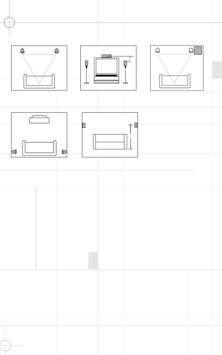
The front speakers should be
plac ed the same distanc e
from each other as they are
from the listening position.
They should be placed at
about the same height from
the floor as the listeners’
ears w ill be, or they may be
angled tow ard the listeners.
The c enter-channel speaker
should be plac ed slightly
behind the front left and right
speakers, and no more than
tw o feet above or below the
tw eeters of the left and right
speakers. It is often c on-
venient to set the c enter
speaker on top of the
television set, as show n
in the draw ing. Use the
supplied support leg to
aim it tow ard the listener
by sc rew ing the leg in to
angle the speaker up, or
unsc rew ing the leg slightly to
angle the speaker dow n.
The tw o surround speakers
should be plac ed slightly
behind the listening position
and, ideally, should fac e
eac h other and be at a level
higher than the listeners’
ears. If that is not possible,
they may be plac ed on a w all
behind the listening position,
fac ing forw ard. The surround
speakers should not c all
attention to themselves.
Experiment w ith their
plac ement until you hear a
diffuse, ambient sound
ac c ompanying the main-
program material heard in
the front speakers.
The low -frequenc y material
reproduced by the
subw oofer is mostly omni-
direc tional, and this speaker
may be plac ed in a c on-
venient loc ation in the room.
How ever, the best repro-
duc tion of bass w ill be heard
w hen the subw oofer is
plac ed in a c orner along the
same w all as the front
speakers. Experiment w ith
subw oofer placement by
temporarily placing the
subw oofer in the listening
position and moving around
the room until the bass
reproduction is best. P lace
the subw oofer in that
loc ation.
Center-Channel
Speaker
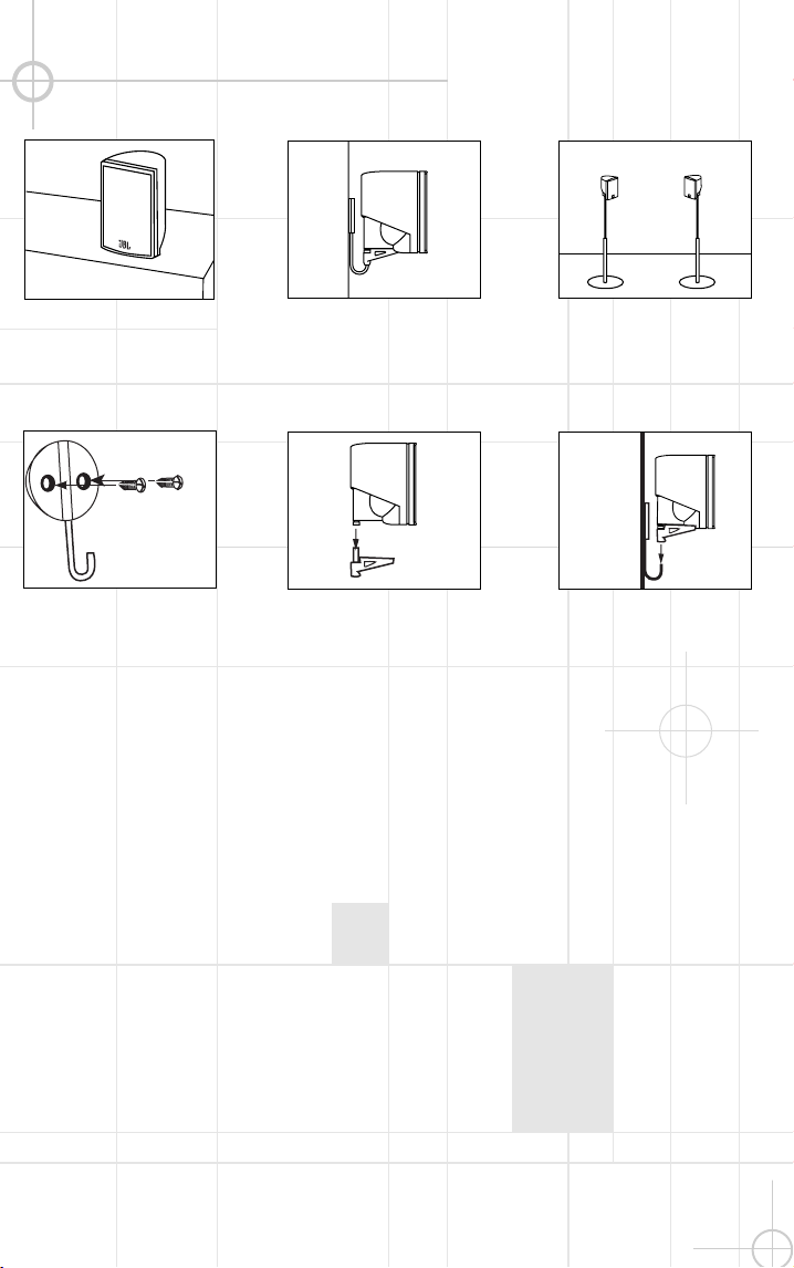
M O U N T I N G O P T I O N S
Satellites and Surrounds
On shelves.
W all-M ounting
A ttac h plate to w all. The
brac kets should be placed,
if possible, so that the
screw s w ill fasten into a
w ooden w all stud. If that is
not possible, use properly
selected w all anchors.
The c ustomer is
responsible for proper
selection and use of
mounting hardw are,
available through
hardw are stores, to
properly and safely
w all-mount the
speakers.
On the w all. W all brac kets
are included.
Slide speaker onto support.
On optional stands (FS300).
P lace speaker and
support on w all plate.
S P E A K E R P L A C E M E N T
4
5
Subw oofer
Surround Speakers
5
– 6 ft.
Front Speakers
0-2 ft.
The front speakers should be
plac ed the same distanc e
from each other as they are
from the listening position.
They should be placed at
about the same height from
the floor as the listeners’
ears w ill be, or they may be
angled tow ard the listeners.
The c enter-channel speaker
should be plac ed slightly
behind the front left and right
speakers, and no more than
tw o feet above or below the
tw eeters of the left and right
speakers. It is often c on-
venient to set the c enter
speaker on top of the
television set, as show n
in the draw ing. Use the
supplied support leg to
aim it tow ard the listener
by sc rew ing the leg in to
angle the speaker up, or
unsc rew ing the leg slightly to
angle the speaker dow n.
The tw o surround speakers
should be plac ed slightly
behind the listening position
and, ideally, should fac e
eac h other and be at a level
higher than the listeners’
ears. If that is not possible,
they may be plac ed on a w all
behind the listening position,
fac ing forw ard. The surround
speakers should not c all
attention to themselves.
Experiment w ith their
plac ement until you hear a
diffuse, ambient sound
ac c ompanying the main-
program material heard in
the front speakers.
The low -frequenc y material
reproduced by the
subw oofer is mostly omni-
direc tional, and this speaker
may be plac ed in a c on-
venient loc ation in the room.
How ever, the best repro-
duc tion of bass w ill be heard
w hen the subw oofer is
plac ed in a c orner along the
same w all as the front
speakers. Experiment w ith
subw oofer placement by
temporarily placing the
subw oofer in the listening
position and moving around
the room until the bass
reproduction is best. P lace
the subw oofer in that
loc ation.
Center-Channel
Speaker
M O U N T I N G O P T I O N S
Satellites and Surrounds
On shelves.
W all-M ounting
A ttac h plate to w all. The
brac kets should be placed,
if possible, so that the
screw s w ill fasten into a
w ooden w all stud. If that is
not possible, use properly
selected w all anchors.
The c ustomer is
responsible for proper
selection and use of
mounting hardw are,
available through
hardw are stores, to
properly and safely
w all-mount the
speakers.
On the w all. W all brac kets
are included.
Slide speaker onto support.
On optional stands (FS300).
P lace speaker and
support on w all plate.
S P E A K E R P L A C E M E N T
6
7
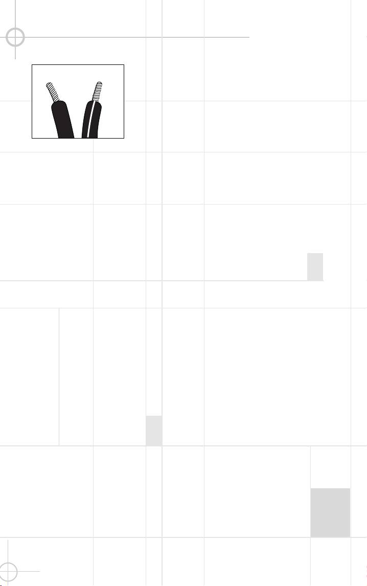
Separate and strip the
ends of the speaker w ire
as show n. Speakers and
elec tronics terminals have
corresponding (+) and (– )
terminals. M ost manu-
fac turers of speakers and
elec tronics, including J BL,
use red to denote the (+)
terminal and blac k for the
(– ) terminal.
The (+) lead of the speaker
w ire is noted w ith a stripe. It
is important to c onnec t both
speakers identically: (+) on
the speaker to (+) on the
amplifier and (– ) on the
speaker to (– ) on the
amplifier. W iring “out of
phase” results in thin sound,
w eak bass and a poor
stereo image.
W ith the advent of
multic hannel surround-
sound systems, c onnec ting
all of the speakers in your
system w ith the c orrect
polarity remains equally
important in order to
preserve the proper
ambienc e and directionality
of the program material.
S P E A K E R C O N N E C T I O N S
Connec tion Tips
Dolby
*
Pro Logic
*
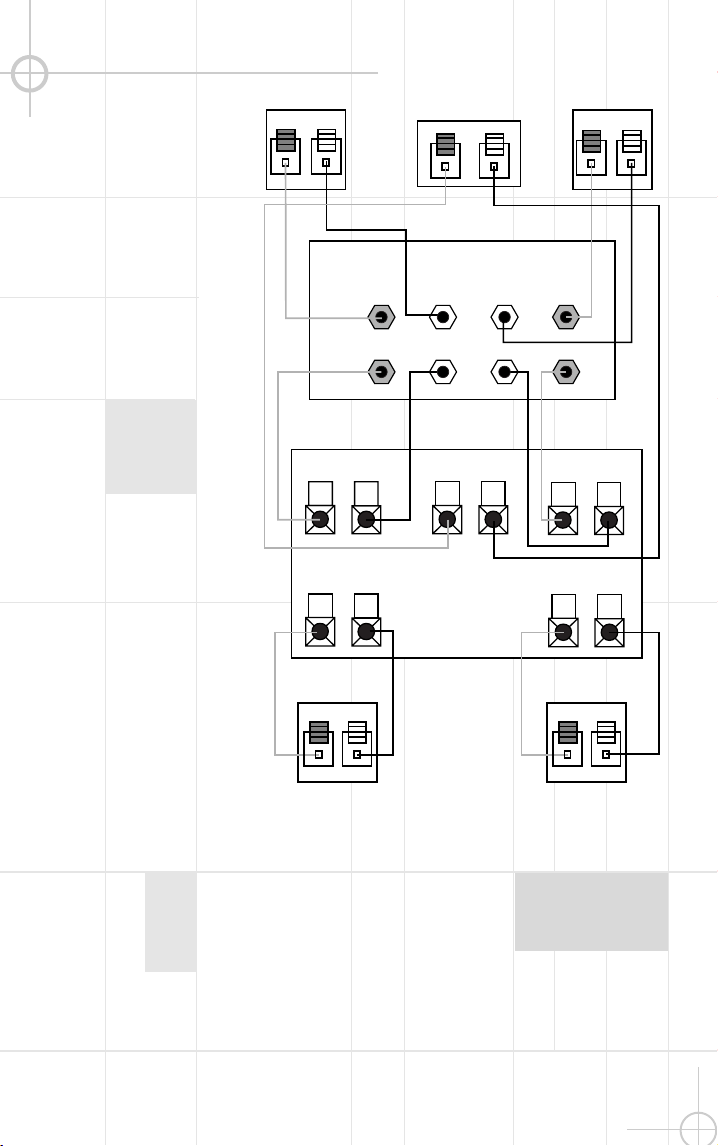
(Non-Digital) – Speaker Level
Use this installation method
for Dolby P ro Logic appli-
cations (not Dolby Digital,
DTS
®
or other digital
processing), w here the
rec eiver/processor does not
have a subw oofer output, or
a volume-c ontrolled preamp
(line-) level output:
Connect your rec eiver or
amplifier’s front left and right
speaker terminals to the left
and right terminals on the
subw oofer that are marked
“High Level In.” Connec t the
left and right terminals on the
subw oofer that are marked
“High Level Out” to the c or-
responding terminals on the
bac k of your front left and
right speakers.
Connect your rec eiver or
amplifier’s c enter, left and
right surround-speaker
terminals to the corre-
sponding terminals on the
bac k of your center, left and
right surround speakers.
Right Front
Right Surround
Left Front
Left Surround
Center
+ – + –
+ –
+ –
+ –
+ –
+ –
Left Front Center
+ –
Left Surround
Right Front
+ –
Right Surround
+ –
Subwoofer
Receiver
HIGH LEVEL
+ – – +
L R
OUT
IN
6
7
Separate and strip the
ends of the speaker w ire
as show n. Speakers and
elec tronics terminals have
corresponding (+) and (– )
terminals. M ost manu-
fac turers of speakers and
elec tronics, including J BL,
use red to denote the (+)
terminal and blac k for the
(– ) terminal.
The (+) lead of the speaker
w ire is noted w ith a stripe. It
is important to c onnec t both
speakers identically: (+) on
the speaker to (+) on the
amplifier and (– ) on the
speaker to (– ) on the
amplifier. W iring “out of
phase” results in thin sound,
w eak bass and a poor
stereo image.
W ith the advent of
multic hannel surround-
sound systems, c onnec ting
all of the speakers in your
system w ith the c orrect
polarity remains equally
important in order to
preserve the proper
ambienc e and directionality
of the program material.
S P E A K E R C O N N E C T I O N S
Connec tion Tips
Dolby
*
Pro Logic
*
(Non-Digital) – Speaker Level
Use this installation method
for Dolby P ro Logic appli-
cations (not Dolby Digital,
DTS
®
or other digital
processing), w here the
rec eiver/processor does not
have a subw oofer output, or
a volume-c ontrolled preamp
(line-) level output:
Connect your rec eiver or
amplifier’s front left and right
speaker terminals to the left
and right terminals on the
subw oofer that are marked
“High Level In.” Connec t the
left and right terminals on the
subw oofer that are marked
“High Level Out” to the c or-
responding terminals on the
bac k of your front left and
right speakers.
Connect your rec eiver or
amplifier’s c enter, left and
right surround-speaker
terminals to the corre-
sponding terminals on the
bac k of your center, left and
right surround speakers.
Right Front
Right Surround
Left Front
Left Surround
Center
+ – + –
+ –
+ –
+ –
+ –
+ –
Left Front Center
+ –
Left Surround
Right Front
+ –
Right Surround
+ –
Subwoofer
Receiver
HIGH LEVEL
+ – – +
L R
OUT
IN
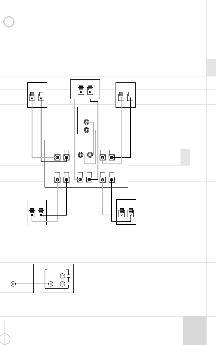
Dolby Pro Logic (N on-Digital) – Line Level
8
9
Use this installation method
for Dolby P ro Logic appli-
cations (not Dolby Digital, DTS
or other digital proc essing),
w here the rec eiver/proc essor
is equipped w ith a subw oofer
output, or a volume-controlled
preamp (line-) level output:
Use RCA -type patch c ords
to c onnec t the line-level
subw oofer outputs on your
rec eiver or amplifier to the
line-level inputs on the
subw oofer. IM P ORTAN T: Do
not use the LFE input on the
subw oofer w ith Dolby
P ro Logic proc essors. N ote: If
your rec eiver or amplifier only
has one subw oofer output
jac k, then you w ill need to use
a Y-c onnector (not included).
P lug the male end of the Y-
connec tor into your rec eiver
or amplifier’s subw oofer
output jac k, and c onnec t each
of the tw o female ends to
separate RCA -type patch
cords. Finally, plug the RCA -
type patch c ords into the line-
level inputs on the subw oofer.
Connect eac h speaker to
the c orresponding speaker
terminals on your rec eiver
or amplifier.
Use this installation method
for Dolby Digital, DTS or other
digital surround proc essors:
Use the line-level input jack
marked “LFE” for the Low -
Frequenc y Effec ts c hannel.
Connect this jac k to the LFE
output or subw oofer output
on your rec eiver or amplifier.
Connect eac h speaker to the
corresponding speaker
terminals on your rec eiver
or amplifier.
M ake sure that you have
configured your surround-
sound proc essor for
“Subw oofer On.” The front
left, front right, center and
rear speakers should all be
set to “S mall.”
Dolby Digital or DTS (or Other Digital Surround M ode) Connection
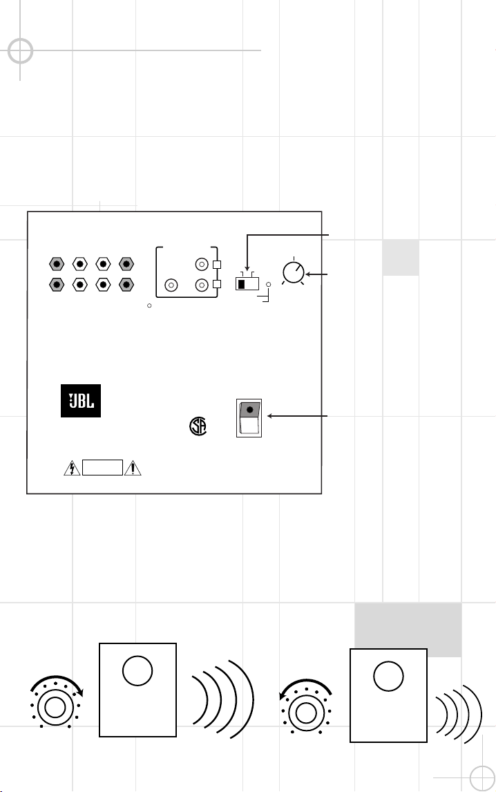
O P E R A T I O N
MIN MAX
Subwoofer�
Level
MIN MAX
Subwoofer�
Level
M ove the M aster P ow er
sw itc h (marked “P ow er”
¡
)
to the “
•
” (On) position to use
the subw oofer. The S CS135
subw oofer w ill automatic ally
turn itself on or go into
standby (sleep) mode w hen
left in the standby mode
(“A uto/On” sw itch
™
in the
“A uto” position). W hen your
rec eiver or amplifier is off, or
is not sending program
material to the subw oofer,
the subw oofer w ill be in
standby mode. W hen the sub-
w oofer senses an audio signal,
it w ill automatic ally turn itself
on. If the subw oofer does
not sense a signal after
approximately tw enty minutes,
it w ill automatic ally go into
standby mode.
W hen the “A uto/On” sw itch
™
is sw itched to the “On”
position, the subw oofer w ill
remain on, w hether or not
program material is playing.
If you w ill be aw ay from
home for an extended period
of time, or if the subw oofer
w ill not be used, sw itc h the
M aster P ow er sw itch
¡
to
the Off position.
Volume
POWER
HIGH LEVEL
+ – – +
SUBWOOFER
LEVEL
CAUTION
RISK OF ELECTRIC SHOCK
DO NOT OPEN
OUT
IN
L R
LINE LEVEL IN
LFE
L
R
AUTO ON
MI N M AX
SUB 135
AC 120V~60Hz
200 Watts
FUSE
2.5A/250V
TYPE T
£�
¡�
™�
IMPORTANT: CONNECT STRIPED WIRE TO RED ( ) SPEAKER TERMINAL.
GREEN: ON
RED: STANDBY
+
LINE LEVEL IN
LFE INPUT
LFE OUT
L
R
SUBWOOFERRECEIVER
Volume c an be adjusted
using the Subw oofer Level
Control
£
(above), as show n
below.
+ –
+ –
+ –
+ –
+ –
+ –
+ –
+ –+ –
+ –
Receiver
Subwoofer �
Out
Left�
Front�
�
Left�
Rear
Right�
Front
Right�
Rear
Subwoofer
R L
R
L
Center
Line-�
Level�
In
Right Surround
Right Front
Left Surround
Left Front
Center
Dolby Pro Logic (N on-Digital) – Line Level
8
9
Use this installation method
for Dolby P ro Logic appli-
cations (not Dolby Digital, DTS
or other digital proc essing),
w here the rec eiver/proc essor
is equipped w ith a subw oofer
output, or a volume-controlled
preamp (line-) level output:
Use RCA -type patch c ords
to c onnec t the line-level
subw oofer outputs on your
rec eiver or amplifier to the
line-level inputs on the
subw oofer. IM P ORTAN T: Do
not use the LFE input on the
subw oofer w ith Dolby
P ro Logic proc essors. N ote: If
your rec eiver or amplifier only
has one subw oofer output
jac k, then you w ill need to use
a Y-c onnector (not included).
P lug the male end of the Y-
connec tor into your rec eiver
or amplifier’s subw oofer
output jac k, and c onnec t each
of the tw o female ends to
separate RCA -type patch
cords. Finally, plug the RCA -
type patch c ords into the line-
level inputs on the subw oofer.
Connect eac h speaker to
the c orresponding speaker
terminals on your rec eiver
or amplifier.
Use this installation method
for Dolby Digital, DTS or other
digital surround proc essors:
Use the line-level input jack
marked “LFE” for the Low -
Frequenc y Effec ts c hannel.
Connect this jac k to the LFE
output or subw oofer output
on your rec eiver or amplifier.
Connect eac h speaker to the
corresponding speaker
terminals on your rec eiver
or amplifier.
M ake sure that you have
configured your surround-
sound proc essor for
“Subw oofer On.” The front
left, front right, center and
rear speakers should all be
set to “S mall.”
Dolby Digital or DTS (or Other Digital Surround M ode) Connection
O P E R A T I O N
MIN MAX
Subwoofer�
Level
MIN MAX
Subwoofer�
Level
M ove the M aster P ow er
sw itc h (marked “P ow er”
¡
)
to the “
•
” (On) position to use
the subw oofer. The S CS135
subw oofer w ill automatic ally
turn itself on or go into
standby (sleep) mode w hen
left in the standby mode
(“A uto/On” sw itch
™
in the
“A uto” position). W hen your
rec eiver or amplifier is off, or
is not sending program
material to the subw oofer,
the subw oofer w ill be in
standby mode. W hen the sub-
w oofer senses an audio signal,
it w ill automatic ally turn itself
on. If the subw oofer does
not sense a signal after
approximately tw enty minutes,
it w ill automatic ally go into
standby mode.
W hen the “A uto/On” sw itch
™
is sw itched to the “On”
position, the subw oofer w ill
remain on, w hether or not
program material is playing.
If you w ill be aw ay from
home for an extended period
of time, or if the subw oofer
w ill not be used, sw itc h the
M aster P ow er sw itch
¡
to
the Off position.
Volume
POWER
HIGH LEVEL
+ – – +
SUBWOOFER
LEVEL
CAUTION
RISK OF ELECTRIC SHOCK
DO NOT OPEN
OUT
IN
L R
LINE LEVEL IN
LFE
L
R
AUTO ON
MI N M AX
SUB 135
AC 120V~60Hz
200 Watts
FUSE
2.5A/250V
TYPE T
£�
¡�
™�
IMPORTANT: CONNECT STRIPED WIRE TO RED ( ) SPEAKER TERMINAL.
GREEN: ON
RED: STANDBY
+
LINE LEVEL IN
LFE INPUT
LFE OUT
L
R
SUBWOOFERRECEIVER
Volume c an be adjusted
using the Subw oofer Level
Control
£
(above), as show n
below.
+ –
+ –
+ –
+ –
+ –
+ –
+ –
+ –+ –
+ –
Receiver
Subwoofer �
Out
Left�
Front�
�
Left�
Rear
Right�
Front
Right�
Rear
Subwoofer
R L
R
L
Center
Line-�
Level�
In
Right Surround
Right Front
Left Surround
Left Front
Center

10
11
If there is no sound from any
of the speakers:
• Chec k that rec eiver/amplifier
is on and a sourc e is playing.
• Chec k that the pow ered
subw oofer is plugged in, its
P ow er sw itch
¡
is sw itc hed
on to the “
•
” position, and the
“A uto/On” sw itch
™
is either
in the “On” or “A uto” position.
• Chec k all w ires and c on-
nec tions betw een rec eiver/
amplifier and speakers. M ake
sure all w ires are c onnected.
M ake sure none of the
speaker w ires are frayed,
cut or punc tured.
• Review proper operation of
your rec eiver/amplifier.
If there is no sound c oming
from one speaker:
• Chec k the “B alanc e” c ontrol
on your rec eiver/amplifier.
• Chec k all w ires and c on-
nec tions betw een rec eiver/
amplifier and speakers. M ake
sure all w ires are c onnected.
M ake sure none of the
speaker w ires are frayed,
cut or punc tured.
• In Dolby Digital or DTS
modes, make sure that the
rec eiver/processor is
configured so that the speaker
in question is enabled.
If there is no sound from the
center speaker:
• Chec k all w ires and
connec tions betw een
rec eiver/amplifier and
speaker. M ake sure all w ires
are c onnec ted. M ake sure
none of the speaker w ires are
frayed, c ut or punctured.
• If your receiver/proc essor is
set in Dolby P ro Logic mode,
make sure the c enter speaker
is not in phantom mode.
• If your receiver/proc essor
is set in Dolby Digital or DTS
mode, make sure the
rec eiver/processor is c on-
figured so that the c enter
speaker is enabled.
If the system plays at low
volumes but shuts off as
volume is inc reased:
• Chec k all w ires and c on-
nec tions betw een rec eiver/
amplifier and speakers. M ake
sure all w ires are c onnected.
M ake sure none of the
speaker w ires are frayed, c ut
or punc tured.
• If more than one pair of main
speakers is being used, check
the minimum impedanc e
requirements of your
rec eiver/amplifier.
If there is low (or no) bass
output:
• M ake sure the c onnec tions
to the left and right “Speaker
Inputs” have the c orrec t
polarity (+ and – ).
• M ake sure the subw oofer
is plugged into an ac tive
elec tric al outlet.
• M ake sure the pow ered
subw oofer is plugged in
and is either in the “On” or
“A uto” position.
• In Dolby Digital or DTS
modes, make sure your
rec eiver/processor is
configured so that the sub-
w oofer and LFE output
are enabled.
If there is no sound from
the surround speakers:
• Chec k all w ires and c on-
nec tions betw een rec eiver/
amplifier and speakers. M ake
sure all w ires are c onnected.
M ake sure none of the
speaker w ires are frayed, c ut
or punc tured.
• Review proper operation of
your rec eiver/amplifier and its
surround-sound features.
• M ake sure the movie or TV
show you are w atching is
rec orded in a surround-sound
mode. If it is not, chec k to see
if your rec eiver/ amplifier has
other surround modes you
may use.
• In Dolby Digital or DTS
modes, make sure your
rec eiver/processor is
configured so that the
surround speakers are
enabled.
• Review the operation of your
DVD player and the jac ket of
your DVD to make sure that
the DVD features the desired
Dolby Digital or DTS mode,
and that you have properly
selected that mode using both
the DVD player’s menu and the
DVD disc’s menu.
T R O U B L E S H O O T I N G
Staple sales invoic e here.
X + 0 + Y
2
0 M
H Z
D E S I G N G O A L :
Bring the thrill of live performanc e and movie sound to
the home environment by calling on J B L’s professional engineering leadership.
S A T E L L I T E T Y P E :
Titanium-laminate-dome tw eeter, sealed enclosure
S U B W O O F E R T Y P E :
Bass-reflex enc losure
P O R T D E S I G N :
FreeFlow ™ flared
P R O F E S S I O N A L R E F E R E N C E :
Cinema Loudspeaker Series
O W N E R ’ S G U I D E
P R O D U C T L I N E :
M O D E L
S C S 135
N U M B E R :
X +
0 +
Y
2
0
M
H Z
4 ”
8 ”
X +
0 +
Y
2
0
M
H Z
J B L Consumer P roducts
250 Crossw ays P ark Drive, W oodbury, N Y 11797
8500 B alboa B oulevard, N orthridge, CA 91329
800-336-4J B L (4525) (USA only)
w w w.jbl.com
©2000 J BL, Inc orporated.
J B L is a registered trademark of J B L, Inc orporated.
Part No.
ai5073
D E S I G N G O A L :
Bring the thrill of live performanc e and movie sound to
the home environment by calling on J B L’s professional engineering leadership.
S A T E L L I T E T Y P E :
Titanium-laminate-dome tw eeter, sealed enclosure
S U B W O O F E R T Y P E :
Bass-reflex enc losure
P O R T D E S I G N :
FreeFlow ™ flared
P R O F E S S I O N A L R E F E R E N C E :
Cinema Loudspeaker Series
O W N E R ’ S G U I D E
P R O S O U N D
C O M E S H O M E
™
P R O D U C T L I N E :
M O D E L
S C S 135
N U M B E R :
S P E C I F I C A T I O N S
Refinements may be made on oc c asion to existing produc ts w ithout notice, but w ill alw ays meet
or exceed original specifications unless otherw ise stated.
Simply Cinema is a registered trademark of J BL, Inc orporated.
* Dolby and P ro Logic are trademarks of Dolby Laboratories.
DTS is a registered trademark of Digital Theater Systems, Inc.
®
®
SCS135 System
Frequenc y Response
35Hz – 20kHz (– 6dB )
Satellites
Recommended Pow er
10 –
100
w atts
Impedance
8 ohms nominal
Sensitivity
86dB @ 1 w att/1 meter
Tw eeter
One 1/2"titanium-laminate
dome, video-shielded
M idrange
One 3" driver, video-shielded
Dimensions (H x W x D)
4-3/8" x 3-3/16" x 3-3/4"
111mm x 81mm x 95mm
W eight
1.1 lb/0.5kg
Center
Recommended Pow er
10 – 50 w atts
Impedance
8 ohms nominal
Sensitivity
86dB @ 1 w att/1 meter
Tw eeter
One 1/2"titanium-laminate
dome, video-shielded
M idrange
Dual 3" drivers, video-shielded
Dimensions (H x W x D)
3-1/4" x 7-5/8" x 3-3/4"
83mm x 194mm x 95mm
W eight
1.89 lb/0.86kg
Subw oofer
Amplifier
100 w atts RM S
Bass
8" w oofer, bass-reflex
enc losure
Dimensions (H x W x D)
15" x 13" x 14"
381mm x 330mm x 356mm
W eight
30 lb/13.6kg