Loading ...
Loading ...
Loading ...
14
1.
2.
3.
4.
5.
6.
INSTALLAT I ON PROCEDURE
WARNING!
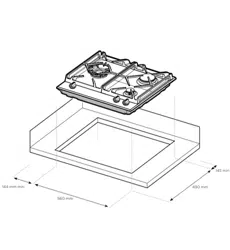
The bench cutout should be made as per cutout
dimensions in Table 2 and Figure 5.
Adjacent walls, cupboards and protection for
combustible materials: Ensure that the appliance
is installed in accordance with AS/NZS 5601.1,
or AS/NZS 5601.2 with regard to clearances
to combustible surfaces and materials, and
clearances to rangehoods and exhaust fans.
To ensure clearances of 200mm from burners
to vertical combustible surfaces observe the
minimum distance requirements shown in Figure 5.
Clearances to combustible surfaces may be
reduced if combustible surfaces are protected
in accordance with AS/NZS 5601.1, or AS/NZS
5601.2.
For existing installations where only the gas
appliance is being replaced
The overhead clearance from the highest part of
the highest burner of this gas appliance to the r
ange hood shall be not less than 600mm and not
less than 750 mm for an exhaust fan.
Any other downward facing combustible surface
less than 600 mm above from the highest part of
the highest burner of this gas appliance shall be
protected for the full width and depth of the hob in
accordance with AS/NZS 5601.
Clearance to any overhead surface shall be not
less than 450 mm.
For all other installations:
Clearance to any overhead surface shall be not less
than 450 mm.
The overhead clearance between the supporting
surface for the cooking vessels (top of the trivets)
of this gas cooking appliance and a range hood or
exhaust fan (overhead clearance) shall be not less
than 650 mm for a range hood, and not less than
750 mm for an exhaust fan.
A Rangehood or exhaust fan shall be installed in
accordance with the range hood or exhaust fan
manufacturer’s relevant instructions.
Where the range hood or exhaust fan manufacturer’s
relevant instructions specify a greater clearance,
then this greater clearance shall apply.
Any other downward facing combustible surface
less than 650 mm above the supporting surface for
the cooking vessels shall be protected for the full
width and depth of the hob in accordance with
AS/NZS 5601.
Failure to fix the cooktop to the bench could result in
loosening of the gas connection through movement of the
cooktop and a gas leak may result.
Four clamps and screws are supplied with 3/4-burner
models and six clamps and screws are supplied with
5-burner models. Fit the clamps as shown in Figure 7 .
When benchtops are less than 33mm in thickness, it may
be necessary to fit a spacer between the benchtop and
each clamp to ensure clamps can be tightened sufficiently
Note 1: Removable accessories such as a wok trivet
that sits upon a hob trivet are not taken into account
in determination of the supporting surface for the
cooking vessels.
Note 2: Minor elevations in trivets such as a wok trivet
formed into a trivet are not taken into account in
determination of the supporting surface for the cooking
vessels.
Note 3: The height of the top of the pan supports
(top of the trivets) with respect to the bench top (built in)
or supporting surface (elevated) or the floor
(freestanding) are detailed separately in these instructions.
For Ceramic Glass models a FOAM SEAL has been
provided and is to be applied along the perimeter of
the hob
Fit the pull down clamps supplied to ensure that the
cooktop cannot move after installation.
Loading ...
Loading ...
Loading ...